
378 - Presse à cintrer tubes RIDGID - Gratis brugsanvisning og manual
Find enhedens vejledning gratis 378 RIDGID i PDF-format.

Pick your language and provide your email: we'll send you a specifically translated version.
Brugerspørgsmål om 378 RIDGID
0 spørgsmål om dette apparat. Besvar dem du kender, eller stil dit eget.
Stil et nyt spørgsmål om dette apparat
Ingen spørgsmål endnu. Vær den første til at stille et.
Download vejledningen til din Presse à cintrer tubes i PDF-format gratis! Find din vejledning 378 - RIDGID og tag din elektroniske enhed tilbage i hånden. På denne side er alle dokumenter nødvendige for brugen af din enhed offentliggjort. 378 af mærket RIDGID.
BRUGSANVISNING 378 RIDGID
Pre-Cut Tube To Correct Length
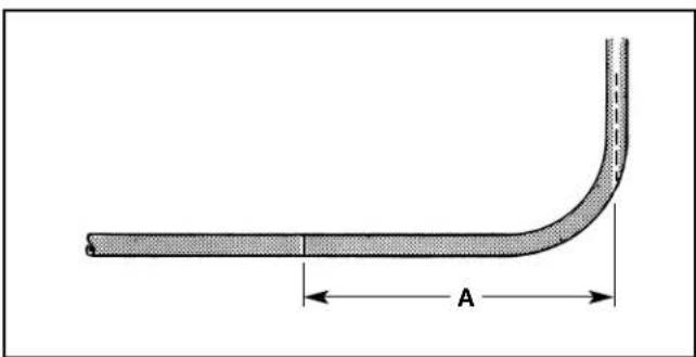
- Add all blueprint center to center dimensions for the total tube length. Mark tube at this total length. (Figure 1)
- Because most blueprints are dimensioned as though all corners were square, less tube is actually required than the total of the blueprint dimensions. Therefore, REDUCE the total length by the number of bends, using the Gain Scales on the Swinging Arm. (See Figure 2)
- Reduce the measured length of tube from Step 1 by one graduation for each 90° bend using the scale marked "90° Gain". Reduce Length of tube by one graduation for each 45° bend using the scale marked "45° Gain". (See Figure 2) Mark tube and cut.
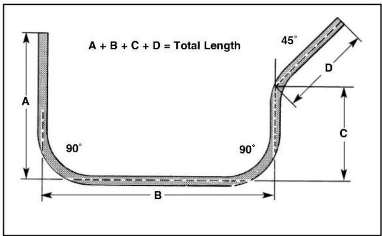
Figure 1
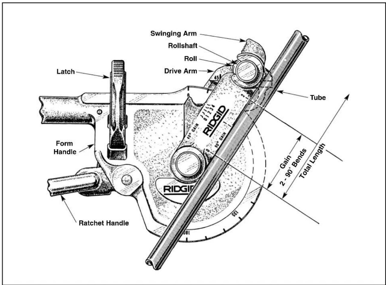
Figure 2
90° Bends
- For first bend, measure from end of tube and mark at blueprint dimension. (Figure 3)
- Raise Latch. Bring handles together to release Drive Arm. Swing Drive Arm counter clockwise until it stops. Move Swinging Arm to clear opening between Form Handle & Roll.
- Position tube in bender. (Figure 4a) If the end from which you measured is in the Form Handle, the measured mark should be directly under the 90° mark on the Drive Arm. (Figure 4a) If, however, the end from which you measured is to the right (Not in the Form Handle), set the mark on the tube directly under the "R" on the Drive Arm. (Figure 4b)
- Close Latch over tube and Swinging Arm over Roll Shaft.
- To Ratchet - Pull Ratchet Handle away from Form Handle. After each pull, Drive Arm will remain locked due to the Holding pawl. Actuate Ratchet Handle until pointer on Swinging Arm is at 90°. Because tubing has a slight springback action, it may be necessary to over bend slightly to allow tube to spring back to 90°.
- To release Bender, follow Step 5.
- If more than one bend is required, measure from center line of the preceding bent leg and mark tube to blueprint dimension (See Figure 5). Position tube in bender as outlined in Step 6.
- For convenience, the Form Handle Clamping Pad may be held in a vise.
45° Bends
- For first bend, measure from end of tube and mark at blueprint dimension.
- Position tube in bender, as illustrated in Figure 4 a-b. When making a 45^ bend, the end from which you measured and marked the tube may be either in the Form Handle or to the right (Not in the Form Handle). In either case, the mark on the tube should be under the 45^ mark on the Drive Arm.
- Close Latch over tube. Move Swinging Arm to engage Roll Shaft.
- To Bend - Follow Step 8 until pointer on Swinging Arm is at 45".
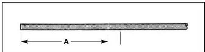
Figure 3
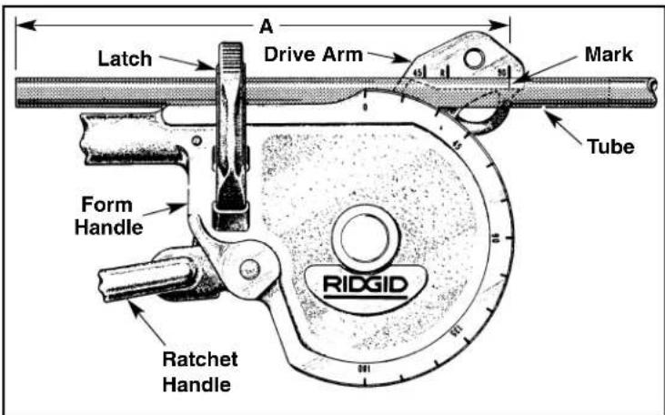
Figure 4a
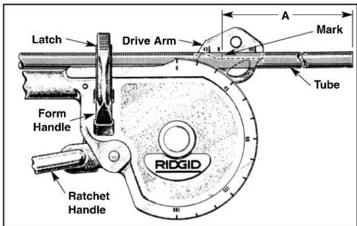
Figure 4b
natural_image
Technical diagram of a bent pipe or duct with labeled dimension A (no text or symbols beyond the label)Figure 5


Indholdsfortegnelse
Klik på en titel for at få adgang til den
Vejledningsassistent
Drevet af Anthropic
Venter på din besked
Produktinformation
Mærke : RIDGID
Model : 378
Kategori : Presse à cintrer tubes