DPU-1 - Niekategoryzowane Karlik - Bezpłatna instrukcja obsługi
Znajdź bezpłatnie instrukcję urządzenia DPU-1 Karlik w formacie PDF.

| Typ produktu | Elektroniczny czujnik / detektor |
| Model | DPU-1 |
| Marka | Karlik |
| Wymiary (dł. x szer. x wys.) | 120 x 80 x 40 mm |
| Waga | 250 g |
| Zasilanie | 2 baterie AA (1,5 V) |
| Pobór mocy | 0,5 W w trybie czuwania, 2 W w trybie aktywnym |
| Zakres pomiaru | 0–100% (w zależności od zastosowania) |
| Dokładność | ±2% |
| Funkcje główne | Pomiar, sygnalizacja dźwiękowa i świetlna, komunikacja bezprzewodowa |
| Zasięg komunikacji | Do 30 m (w otwartej przestrzeni) |
| Materiał obudowy | Tworzywo ABS |
| Kolor | Biały z szarymi elementami |
| Temperatura pracy | 0°C do 40°C |
| Wilgotność pracy | 10% – 90% (bez kondensacji) |
| Klasa ochrony | IP20 (tylko do użytku wewnętrznego) |
| Montaż | Na ścianie lub na stole za pomocą dołączonej podstawy |
| Zawartość zestawu | Urządzenie, instrukcja obsługi, baterie (opcjonalnie) |
| Czyszczenie i konserwacja | Przecierać miękką, suchą szmatką; nie używać rozpuszczalników |
| Środki ostrożności | Nie wystawiać na bezpośrednie działanie wody; chronić przed upadkiem |
| Części zamienne | Baterie, podstawka (dostępne u producenta) |
| Serwis i naprawa | W razie awarii skontaktuj się z autoryzowanym serwisem |
Często zadawane pytania - DPU-1 Karlik
Pytania użytkowników dotyczące DPU-1 Karlik
0 pytanie dotyczące tego urządzenia. Odpowiedz na te, które znasz, lub zadaj własne.
Zadaj nowe pytanie dotyczące tego urządzenia
Pobierz instrukcję dla swojego Niekategoryzowane w formacie PDF za darmo! Znajdź swoją instrukcję DPU-1 - Karlik i weź swoje urządzenie elektroniczne z powrotem w ręce. Na tej stronie opublikowane są wszystkie dokumenty niezbędne do korzystania z urządzenia. DPU-1 marki Karlik.
INSTRUKCJA OBSŁUGI DPU-1 Karlik
ASSEMBLY MANUAL OF RTV AND RTV-SAT OUTLET SOCKETS
- Prepare end of the antenna cable for installation, i.e. strip the wire of the coaxial cable by cutting at the same height the external insulation, over-wrap and the centre of the cable. (picture no. 1)
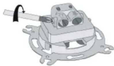
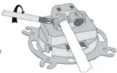
- Unscrew the clamping bolt in the antenna outlet socket (picture no. 2).
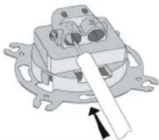
- Insert the antenna cable so as blade of the socket enters between the over-wrap and the external insulation. Check if the wires of the cable are inserted into the input clamp in a correct way (picture no. 4).
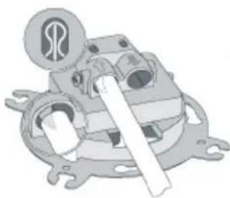
- Tighten the clamping bolt in the antenna outlet socket (picture no. 5).
- For pass-through sockets - procedure for socket output is the same as for socket input.
- Insert the socket into the 60mm installation box and according to the type of box assembly the socket with either the spikes or the fastening screws.
- Place the frame with the cap on the main body of the outlet socket..
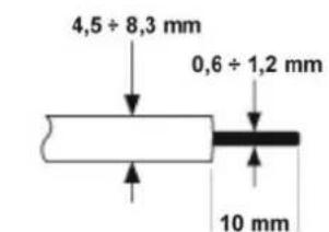
PICTURE NO.1
natural_image
Mechanical assembly diagram showing a clamp holding a component (no text or symbols visible)PICTURE NO.2
natural_image
Mechanical component diagram showing a lever mechanism with no visible text or symbolsPICTURE NO.3
natural_image
Mechanical assembly diagram showing a motor or gear mechanism with no visible text or symbolsPICTURE NO.4
natural_image
Mechanical assembly diagram showing a lever mechanism with no visible text or symbolsPICTURE NO.5
NOTE!
Assembly shall be held by a suitably qualified person with deactivated voltage and shall meet the national safety standards.