9RV-4 - Cyfrowy wyłącznik czasowy Karlik - Bezpłatna instrukcja obsługi
Znajdź bezpłatnie instrukcję urządzenia 9RV-4 Karlik w formacie PDF.

| Typ produktu | Cyfrowy wyłącznik czasowy |
| Model | 9RV-4 |
| Marka | Karlik |
| Wymiary (szer. x wys. x gł.) | 72 x 72 x 45 mm |
| Masa | 0,1 kg |
| Zasilanie | 230 V AC, 50 Hz |
| Maksymalne obciążenie | 16 A (rezystancyjne) |
| Wyświetlacz | Cyfrowy LED |
| Programowanie | Dzienny/tygodniowy, do 8 włączników/wyłączników |
| Funkcja losowa | Tak (symulacja obecności) |
| Funkcja letnia/zimowa | Automatyczna zmiana czasu |
| Stopień ochrony | IP20 |
| Montaż | Naścienny (w puszce podtynkowej) |
| Temperatura pracy | 0°C do +40°C |
| Materiał obudowy | Tworzywo sztuczne |
| Kolor | Biały |
| Zasilanie rezerwowe | Bateria litowa CR2032 (podtrzymanie ustawień) |
| Liczba kanałów | 1 |
| Czyszczenie | Suchą szmatką, bez użycia rozpuszczalników |
| Bezpieczeństwo | Przeznaczony do użytku wewnętrznego, zgodny z normami CE |
| Gwarancja | 2 lata |
Często zadawane pytania - 9RV-4 Karlik
Pytania użytkowników dotyczące 9RV-4 Karlik
0 pytanie dotyczące tego urządzenia. Odpowiedz na te, które znasz, lub zadaj własne.
Zadaj nowe pytanie dotyczące tego urządzenia
Pobierz instrukcję dla swojego Cyfrowy wyłącznik czasowy w formacie PDF za darmo! Znajdź swoją instrukcję 9RV-4 - Karlik i weź swoje urządzenie elektroniczne z powrotem w ręce. Na tej stronie opublikowane są wszystkie dokumenty niezbędne do korzystania z urządzenia. 9RV-4 marki Karlik.
INSTRUKCJA OBSŁUGI 9RV-4 Karlik
ASSEMBLY MANUAL OF RTV AND RTV-SAT OUTLET SOCKETS
- Prepare end of the antenna cable for installation, i.e. strip the wire of the coaxial cable by cutting at the same height the external insulation, over-wrap and the centre of the cable. (picture no. 1)
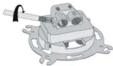
- Unscrew the clamping bolt in the antenna outlet socket (picture no. 2).
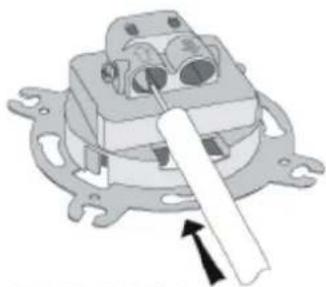
- Insert the antenna cable so as blade of the socket enters between the over-wrap and the external insulation. Check if the wires of the cable are inserted into the input clamp in a correct way (picture no. 4).
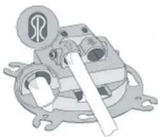
- Tighten the clamping bolt in the antenna outlet socket (picture no. 5).
- For pass-through sockets - procedure for socket output is the same as for socket input.
- Insert the socket into the 60mm installation box and according to the type of box assembly the socket with either the spikes or the fastening screws.
- Place the frame with the cap on the main body of the outlet socket..
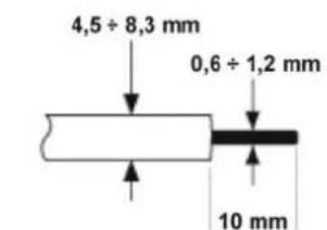
PICTURE NO.1
natural_image
Mechanical assembly diagram showing a clamp holding a component (no text or symbols visible)PICTURE NO.2
natural_image
Mechanical component diagram showing a lever mechanism with no visible text or symbolsPICTURE NO.3
natural_image
Mechanical assembly diagram showing a motor or gear mechanism with no visible text or symbolsPICTURE NO.4
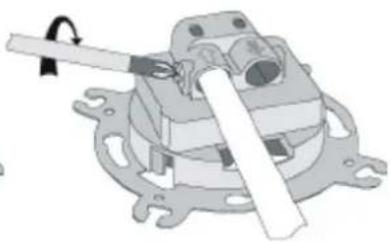
natural_image
Mechanical assembly diagram showing a lever mechanism with no visible text or symbolsPICTURE NO.5
NOTE!
Assembly shall be held by a suitably qualified person with deactivated voltage and shall meet the national safety standards.