0-12-DRS-4 - Gniazdo ścienne Karlik - Bezpłatna instrukcja obsługi
Znajdź bezpłatnie instrukcję urządzenia 0-12-DRS-4 Karlik w formacie PDF.

| Typ produktu | Gniazdo ścienne |
| Model | 0-12-DRS-4 |
| Marka | Karlik |
| Materiał | Tworzywo sztuczne (termoutwardzalne) |
| Kolor | Biały (standardowo) |
| Wymiary (wys. x szer. x gł.) | 80 x 80 x 30 mm |
| Waga | Około 100 g |
| Napięcie znamionowe | 230 V AC |
| Prąd znamionowy | 16 A |
| Częstotliwość | 50 Hz |
| Liczba gniazd | 1 |
| Rodzaj wtyczki | Typ E (francuski) / F (Schuko) |
| Zabezpieczenie dziecięce | Tak, przesłony |
| Stopień ochrony IP | IP20 |
| Montaż | Podtynkowy / natynkowy (w zależności od puszki) |
| Przeznaczenie | Instalacje domowe i biurowe |
| Klasa ochronności | Klasa II (podwójna izolacja) |
| Zaciski przyłączeniowe | Zaciski śrubowe do przewodów do 2,5 mm² |
| Zgodność z normami | PN-EN 60669-1, PN-EN 60884-1 |
| Czyszczenie i konserwacja | Przecierać suchą szmatką, nie używać detergentów |
| Części zamienne | Brak dostępnych części zamiennych; w przypadku uszkodzenia wymienić całe gniazdo |
Często zadawane pytania - 0-12-DRS-4 Karlik
Pytania użytkowników dotyczące 0-12-DRS-4 Karlik
0 pytanie dotyczące tego urządzenia. Odpowiedz na te, które znasz, lub zadaj własne.
Zadaj nowe pytanie dotyczące tego urządzenia
Pobierz instrukcję dla swojego Gniazdo ścienne w formacie PDF za darmo! Znajdź swoją instrukcję 0-12-DRS-4 - Karlik i weź swoje urządzenie elektroniczne z powrotem w ręce. Na tej stronie opublikowane są wszystkie dokumenty niezbędne do korzystania z urządzenia. 0-12-DRS-4 marki Karlik.
INSTRUKCJA OBSŁUGI 0-12-DRS-4 Karlik
ASSEMBLY MANUAL OF RTV AND RTV-SAT OUTLET SOCKETS
- Prepare end of the antenna cable for installation, i.e. strip the wire of the coaxial cable by cutting at the same height the external insulation, over-wrap and the centre of the cable. (picture no. 1)
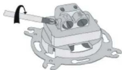
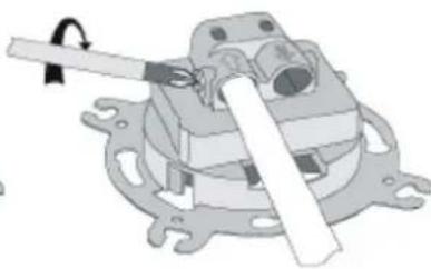
- Unscrew the clamping bolt in the antenna outlet socket (picture no. 2).
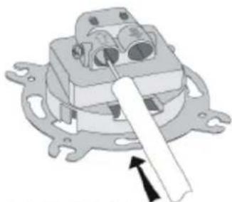
- Insert the antenna cable so as blade of the socket enters between the over-wrap and the external insulation. Check if the wires of the cable are inserted into the input clamp in a correct way (picture no. 4).
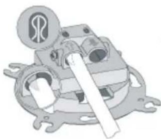
- Tighten the clamping bolt in the antenna outlet socket (picture no. 5).
- For pass-through sockets - procedure for socket output is the same as for socket input.
- Insert the socket into the 60mm installation box and according to the type of box assembly the socket with either the spikes or the fastening screws.
- Place the frame with the cap on the main body of the outlet socket..
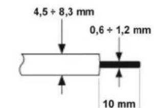
PICTURE NO.1
natural_image
Mechanical assembly diagram showing a clamp holding a component with multiple ports and mounting flanges (no text or symbols)PICTURE NO.2
natural_image
Mechanical component diagram showing a housing with mounting flanges and a central shaft (no text or symbols)PICTURE NO.3
natural_image
Mechanical assembly diagram showing a motor or gear mechanism with no visible text or symbolsPICTURE NO.4
natural_image
Mechanical assembly diagram showing a lever mechanism with no visible text or symbolsPICTURE NO.5
NOTE!
Assembly shall be held by a suitably qualified person with deactivated voltage and shall meet the national safety standards.