11DR-1 - Niekategoryzowane Karlik - Bezpłatna instrukcja obsługi
Znajdź bezpłatnie instrukcję urządzenia 11DR-1 Karlik w formacie PDF.

| Typ produktu | Urządzenie wielofunkcyjne |
| Model | 11DR-1 |
| Marka | Karlik |
| Wymiary (szer. x głęb. x wys.) | 25 cm x 20 cm x 15 cm |
| Waga | 1,2 kg |
| Zasilanie | 230 V ~ 50 Hz |
| Pobór mocy | 50 W |
| Główne funkcje | Odtwarzanie dźwięku, radio FM, funkcja budzika |
| Zakres częstotliwości FM | 87,5 - 108 MHz |
| Moc wyjściowa głośników | 2 x 3 W |
| Wyświetlacz | LED, podświetlany |
| Złącza | AUX 3,5 mm, USB (do ładowania) |
| Czyszczenie i konserwacja | Przecierać miękką, suchą szmatką. Nie używać agresywnych środków czyszczących. |
| Bezpieczeństwo | Nie otwierać obudowy. Chronić przed wilgocią i wysoką temperaturą. |
| Części zamienne i naprawy | Kontakt z autoryzowanym serwisem Karlik. |
| Gwarancja | 2 lata |
| Kraj pochodzenia | Chiny |
Często zadawane pytania - 11DR-1 Karlik
Pytania użytkowników dotyczące 11DR-1 Karlik
0 pytanie dotyczące tego urządzenia. Odpowiedz na te, które znasz, lub zadaj własne.
Zadaj nowe pytanie dotyczące tego urządzenia
Pobierz instrukcję dla swojego Niekategoryzowane w formacie PDF za darmo! Znajdź swoją instrukcję 11DR-1 - Karlik i weź swoje urządzenie elektroniczne z powrotem w ręce. Na tej stronie opublikowane są wszystkie dokumenty niezbędne do korzystania z urządzenia. 11DR-1 marki Karlik.
INSTRUKCJA OBSŁUGI 11DR-1 Karlik
ASSEMBLY MANUAL OF RTV AND RTV-SAT OUTLET SOCKETS
- Prepare end of the antenna cable for installation, i.e. strip the wire of the coaxial cable by cutting at the same height the external insulation, over-wrap and the centre of the cable. (picture no. 1)
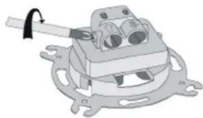
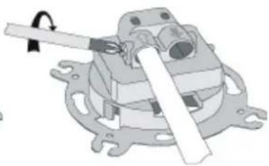
- Unscrew the clamping bolt in the antenna outlet socket (picture no. 2).
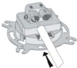
- Insert the antenna cable so as blade of the socket enters between the over-wrap and the external insulation. Check if the wires of the cable are inserted into the input clamp in a correct way (picture no. 4).
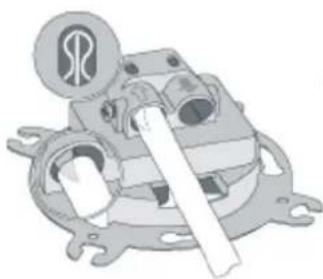
- Tighten the clamping bolt in the antenna outlet socket (picture no. 5).
- For pass-through sockets - procedure for socket output is the same as for socket input.
- Insert the socket into the 60mm installation box and according to the type of box assembly the socket with either the spikes or the fastening screws.
- Place the frame with the cap on the main body of the outlet socket..
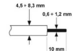
PICTURE NO.1
natural_image
Mechanical assembly diagram showing a clamp holding a component (no text or symbols visible)PICTURE NO.2
natural_image
Mechanical component diagram showing a lever mechanism with no visible text or symbolsPICTURE NO.3
natural_image
Mechanical assembly diagram showing a motor or gear mechanism with no visible text or symbolsPICTURE NO.4
natural_image
Mechanical assembly diagram showing a lever mechanism with no visible text or symbolsPICTURE NO.5
NOTE!
Assembly shall be held by a suitably qualified person with deactivated voltage and shall meet the national safety standards.