27DRPZ - Niekategoryzowane Karlik - Bezpłatna instrukcja obsługi
Znajdź bezpłatnie instrukcję urządzenia 27DRPZ Karlik w formacie PDF.

| Typ produktu | Monitor komputerowy |
| Przekątna ekranu | 27 cali (68,6 cm) |
| Rozdzielczość | 1920 x 1080 (Full HD) |
| Technologia panelu | IPS |
| Częstotliwość odświeżania | 60 Hz |
| Czas reakcji | 5 ms |
| Jasność | 250 cd/m² |
| Kontrast statyczny | 1000:1 |
| Złącza | HDMI, DisplayPort, VGA |
| Pobór mocy (typowy) | 30 W |
| Waga (z podstawą) | ok. 4,5 kg |
| Wymiary (z podstawą) | 620 x 450 x 200 mm |
| Zakres napięcia | 100-240 V AC, 50/60 Hz |
| Kolor obudowy | Czarny |
| Regulacja nachylenia | Tak (-5° do 20°) |
| Zabezpieczenia | Gniazdo Kensington |
| Zawartość opakowania | Monitor, kabel HDMI, kabel zasilający, instrukcja obsługi |
Często zadawane pytania - 27DRPZ Karlik
Pytania użytkowników dotyczące 27DRPZ Karlik
0 pytanie dotyczące tego urządzenia. Odpowiedz na te, które znasz, lub zadaj własne.
Zadaj nowe pytanie dotyczące tego urządzenia
Pobierz instrukcję dla swojego Niekategoryzowane w formacie PDF za darmo! Znajdź swoją instrukcję 27DRPZ - Karlik i weź swoje urządzenie elektroniczne z powrotem w ręce. Na tej stronie opublikowane są wszystkie dokumenty niezbędne do korzystania z urządzenia. 27DRPZ marki Karlik.
INSTRUKCJA OBSŁUGI 27DRPZ Karlik
ASSEMBLY MANUAL OF RTV AND RTV-SAT OUTLET SOCKETS
- Prepare end of the antenna cable for installation, i.e. strip the wire of the coaxial cable by cutting at the same height the external insulation, over-wrap and the centre of the cable. (picture no. 1)
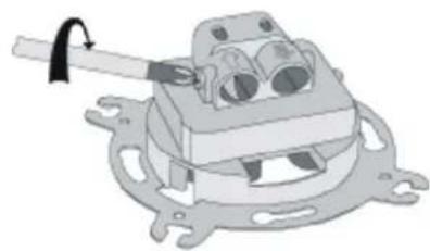
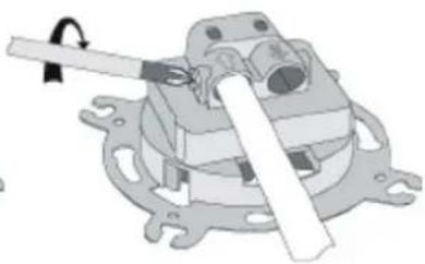
- Unscrew the clamping bolt in the antenna outlet socket (picture no. 2).
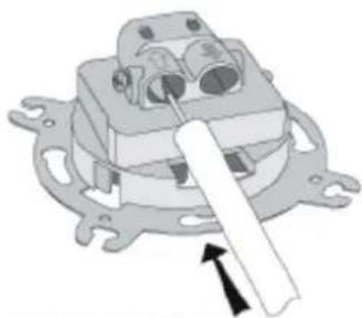
- Insert the antenna cable so as blade of the socket enters between the over-wrap and the external insulation. Check if the wires of the cable are inserted into the input clamp in a correct way (picture no. 4).
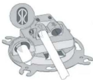
- Tighten the clamping bolt in the antenna outlet socket (picture no. 5).
- For pass-through sockets - procedure for socket output is the same as for socket input.
- Insert the socket into the 60mm installation box and according to the type of box assembly the socket with either the spikes or the fastening screws.
- Place the frame with the cap on the main body of the outlet socket..
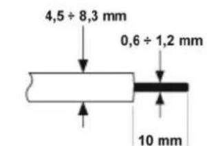
PICTURE NO.1
natural_image
Mechanical assembly diagram showing a clamp holding a component (no text or symbols visible)PICTURE NO.2
natural_image
Mechanical component diagram showing a lever mechanism with no visible text or symbolsPICTURE NO.3
natural_image
Mechanical assembly diagram showing a motor or gear mechanism with no visible text or symbolsPICTURE NO.4
natural_image
Mechanical assembly diagram showing a lever mechanism with no visible text or symbolsPICTURE NO.5
NOTE!
Assembly shall be held by a suitably qualified person with deactivated voltage and shall meet the national safety standards.