F50DP - Aparat fotograficzny NIKON - Bezpłatna instrukcja obsługi
Znajdź bezpłatnie instrukcję urządzenia F50DP NIKON w formacie PDF.

| Typ produktu | Aparat fotograficzny analogowy (SLR) |
| Model | F50DP |
| Marka | Nikon |
| Format filmu | 35mm (135) |
| Mocowanie obiektywu | Nikon F |
| Migawka | Elektronicznie sterowana, szczelinowa pionowa; 30 s – 1/2000 s |
| Pomiar światła | TTL, matrycowy 3D, centralnie ważony, punktowy |
| Czułość ISO | 25–5000 (DX kod, ręczne ustawienie) |
| Tryby ekspozycji | Program AE, priorytet przysłony, priorytet migawki, ręczny |
| Kompensacja ekspozycji | ±3 EV w skoku co 1/3 EV |
| Samowyzwalacz | Elektroniczny, 10 s |
| Wyświetlacz | LCD w wizjerze i na górnym panelu |
| Zasilanie | 2 baterie 3V CR123A |
| Wymiary (szer. × wys. × gł.) | ok. 154 × 96 × 70 mm |
| Waga | ok. 590 g (bez obiektywu i baterii) |
| Materiał korpusu | Tworzywo sztuczne wzmocnione |
| Czyszczenie | Przecierać miękką, suchą ściereczką; unikać rozpuszczalników |
| Bezpieczeństwo | Nie patrzeć przez wizjer na słońce; przechowywać poza zasięgiem dzieci |
| Części zamienne i naprawy | Autoryzowane serwisy Nikon; dostępne elementy mechaniczne i elektroniczne |
| Informacje ogólne | Instrukcja w formacie PDF dostępna na stronie producenta |
Często zadawane pytania - F50DP NIKON
Pytania użytkowników dotyczące F50DP NIKON
0 pytanie dotyczące tego urządzenia. Odpowiedz na te, które znasz, lub zadaj własne.
Zadaj nowe pytanie dotyczące tego urządzenia
Pobierz instrukcję dla swojego Aparat fotograficzny w formacie PDF za darmo! Znajdź swoją instrukcję F50DP - NIKON i weź swoje urządzenie elektroniczne z powrotem w ręce. Na tej stronie opublikowane są wszystkie dokumenty niezbędne do korzystania z urządzenia. F50DP marki NIKON.
INSTRUKCJA OBSŁUGI F50DP NIKON
| 作成承認印 | 配布許可印 |
 | 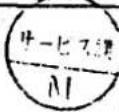 |
Nikon F50 FAA29051
F50D
FAA29251
F50DP
FAA29351
N50
FAA29151
REPAIR MANUAL
Nikon
NIKON CORPORATION
Tokyo, Japan
© Copyright 1994 ALL RIGHTS RESERVED 無断転載を禁ず!!
Contents
Operation and display specifications
Simple mode M2
Advanced mode M3
-
General-purpose program mode in programmed auto exposure mode ....M3
-
Other program modes (common to other seven modes) in programmed auto exposure mode ....M4
-
Shutter-priority auto exposure mode (S) M4
-
Aperture-priority auto exposure mode (A) .....M5
-
Manual exposure mode M5
-
Exposure mode memory M6
-
Selecting AF mode M7
-
Setting and confirming film speed ..... M7
-
Exposure compensation M8
-
Instant reset M9
-
Self-timer operation M9
-
AE lock M10
-
Shutter pre-release timer ....M11
-
Frame counter M11
Warning indication
(1) Battery is exhausted....M12
(2) Film rewind completion ..... M13
(3) Film is being rewound. M13
(4) Sequence error ....M14
(5) Automatic film loading error ..... M15
(6) Film rewind error ....M15
(7) Loading non-DX-coded film in Simple mode.....M16
(8) Non-CPU lens is mounted or no lens is mounted. (In other than M mode) ....M17
(9) Non-CPU lens is mounted, or no lens is mounted. (In M mode) M18
(10) Minimum aperture reset error ..... M18
(11) External flash is not set to TTL mode. M19
(12) Time warning indication in S mode .....M20
(13) AF does not work correctly. M21
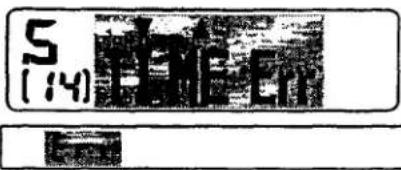
(14) No film is loaded. M21
(15) Changing the combination of shutter speed/aperture M22
(16) Flash fires at full output ..... M22
(17) Flash fires at full output M23
(18) Insufficient battery power warning .....M23
(19) Overexposure possibility ..... M24
(20) Underexposure possibility ..... M25
(21) Camera shake M26
Operation and display specifications
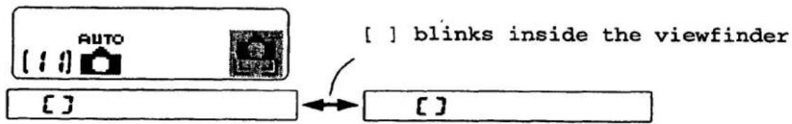
Simple mode (common to all four programs)
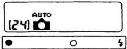
(1) Set/adjust buttons are invalid. Press the menu button to display the menu.
(2) In-focus indicator ( · ), correct exposure indicator (o), and flash ready-light ( ) indicator appear in the viewfinder.
(3) No change of shutter speed/aperture combination is available.
(4) No shutter speed and aperture values are displayed in the LCD panel.
(5) Basically no shutter speed and aperture values appear in the viewfinder. However, this becomes possible by optional setting. In this case, no exposure indicator (o) appears.
- Optional setting
With the following operations, shutter speed and aperture values can be displayed in the viewfinder.
I. Change the shooting mode to SIMPLE mode.
II. Turn the power switch OFF.
III. Turn the power switch ON while holding down the menu button.
IV. Now it is possible to display shutter speed and aperture values.
V. Repeat the above operations to go back to the original mode.
Note:
In the SIMPLE mode, only necessary indicators are displayed in the viewfinder for easy shooting for all users. As a result, no shutter speed and aperture values are displayed. But, we have incorporated an optional function for easy checking at production and service sections. This function is confidential, except for users who really want to display those values in the viewfinder.
Advanced mode
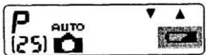
- General-purpose program mode in programmed auto exposure mode
(1) It is possible to choose the combination of shutter speed and aperture for a correct exposure with the set/adjust button corresponding to the up (Δ) and down (∇ marks. Other buttons are invalid.
(2) When using a flash, the up ( ) and down ( ) marks disappear and the change of a combination of shutter speed/aperture is not possible. (No up ( ) and down ( ) marks appear.)
(3) Press the menu button to return to the menu.
(4) Shutter speed and aperture values are displayed in the viewfinder.
(5) Shutter speed and aperture values are displayed in the LCD panel.
Change of a combination of shutter speed/aperture
(1) Exposure mode to change the combination of shutter speed/aperture.
- This is only possible in programmed auto exposure mode in advanced shooting mode with no flash.
- Change of a combination of shutter speed/aperture is not possible when using flash. Although choosing an optional mode to display both shutter speed and aperture values in simple mode, the change of a combination of shutter speed/aperture is not possible. (No up ( ) and down ( marks appear.)
(2) Display of the change of a combination of shutter speed/aperture
![(Before setting) P AUTO [24] → (After setting) P AUTO P* [24] 125 F5.6 60 F8](/content/2026/05/1131009/images/afa80bff376735c3cdfef5d97d72be86ec531c10f3d36defe771e3e8845c96d6.jpg)
(3) Setting the change of a combination of shutter speed/aperture
- Press the down ( ) button to change the aperture value in 1/2 steps to the open aperture side, and press the up ( ) button to change the aperture value in 1/2 steps to the minimum aperture side.
-
Continue to press the button to advance the value quickly in 1/2 EV steps at 2Hz.
-
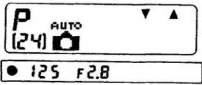
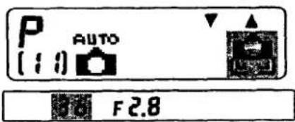
Other program modes (common to other seven modes) in programmed auto exposure mode
● 125 F2
(1) Set/adjust buttons are invalid. Press the menu button to display the exposure mode menu.
(2) Shutter speed and aperture values are displayed in the viewfinder.
(3) No shutter speed and aperture values are displayed in the LCD panel.
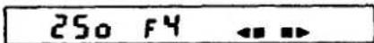
- Shutter-priority auto exposure mode (S)
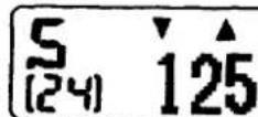
125 F2.8
(1) Press the set/adjust button corresponding to the up (Δ) and (∇) down marks to set the shutter speed. No other buttons are invalid.
(2) Press the menu button to go to the exposure mode menu.
(3) Shutter speed and aperture values are displayed in the viewfinder.
(4) Shutter speed values only are displayed in the LCD panel.
(5) Set the shutter speed values and displays in 1/2 steps.
(6) To set the shutter speed continue to press the set/adjust button for more than 1 second to advance the value quickly in 1/2 steps at 2Hz.
(7) Shutter speeds ranging from 1/2000 sec. to 30 sec can be set.
(8) Setting is possible up to the fastest speed of 1/2000 sec. and down to the slowest speed, of 30 sec. Once either 1/2000 or 30 sec has been reached, you must press the opposite arrow to change the speed setting.
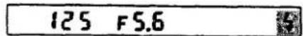
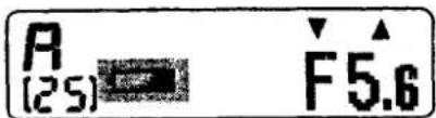
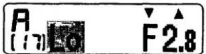
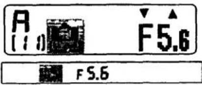
4. Aperture-priority auto exposure mode (A)
- Set and display the aperture values from the camera body side. Accordingly do not turn the lens aperture ring. (Always set the lens aperture ring to the minimum.)
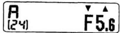
● 125 F5.6
(1) Press the set/adjust button corresponding to the up ( ) and () down marks to set the shutter speed. No other buttons are valid.
(2) Press the menu button to go to the exposure mode menu.
(3) Shutter speed and aperture values are displayed in the viewfinder.
(4) Shutter speed values only are displayed in the LCD panel.
(5) Set the shutter speed values and displays in 1/2 steps. But set wide open aperture values by 1/6 step increments.
(6) To set the shutter speed, continue to press the set/adjust button for more than 1 second to advance the value quickly by 1/2 step at 2Hz.
5. Manual exposure mode
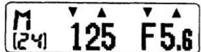
● 125 F5.6 +•○•-
(1) Set the shutter speed and aperture values with the set/adjust button.
(2) Press the menu button to go to the exposure mode menu.
(3) Shutter speed and aperture values are displayed in the viewfinder.
(4) Shutter speed and aperture values are displayed in the LCD panel.
(5) Setting of the shutter speed is the same as that of the shutter-priority auto exposure mode except for the Time setting.
(6) Shutter speed can be set ranging from 1/2000 sec. to 30 sec. and Time setting.
(7) If shutter speed is set to a value slower than 30 sec., it becomes the Time setting.
(8) Setting is possible up to the highest of 1/2000 sec. and the slowest of 30 sec. Shifting continuously from 1/2000 sec. to 30 sec. is not possible.
(9) During shooting in the Time setting, the self-timer LED blinks at 1Hz. The back light in the viewfinder goes out.
(10) Setting of aperture value is the same as with the aperture-priority auto exposure modes.
(11) Exposure indicator
| Exposure indicator | EV : difference from the correct exposure value |
| +·○··-◀■■ | EV +1.5 |
| +·○··-■■ | +1.5 > EV +0.5 |
| +·○··-■ | +0.5 > EV > -0.5 |
| +·○··-■■ | -0.5 ≥ EV > -1.5 |
| +·○··-■▶ | -1.5 ≥ EV |
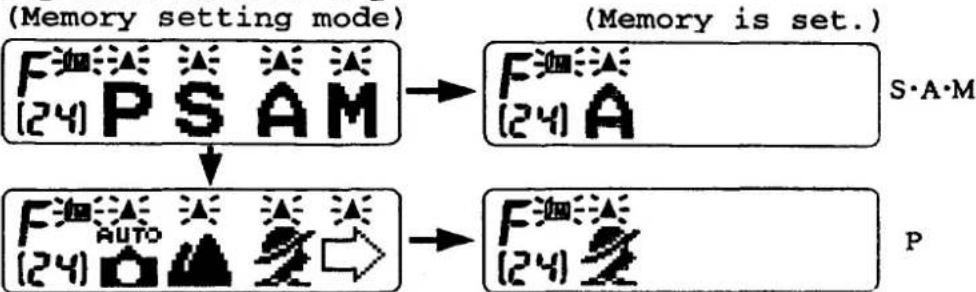
6. Exposure mode memory
flowchart
graph TD
    A["(Memory setting mode)"] --> B["F (24) P S A M"]
    B --> C["F (24) A"]
    D["F (24) AUTO"] --> E["→"]
    E --> F["F (24) Z"]
    style A fill:#f9f,stroke:#333
    style D fill:#f9f,stroke:#333
    style B fill:#ccf,stroke:#333
    style C fill:#ccf,stroke:#333
    style F fill:#ccf,stroke:#333
(1) Setting memory
1) Select the symbol (M) in the optional-function menu to activate the Memory setting mode.
2) Press the set/adjust button to select the desired exposure mode to be memorized. The symbol (M) blinks.
3) When the exposure mode is selected, the menu displays the exposure mode to be memorized. Press the button above the corresponding symbol, the exposure mode to be set will be memorized in the camera body. The symbol (M) lights up and returns back to the optional-function menu. (M)
4) When the menu button is pressed while exposure modes to be memorized are displayed, the memory setting screen appears. Pressing the menu button while the symbol (M) is blinking returns the LCD panel to the optional-function menu.
(2) Recalling memory
1) In Advanced mode, press the menu button for over 2 seconds, the memorized exposure mode can be recalled in any mode.
2) If no memory function is memorized, the LCD panel returns to the general-purpose program mode in programmed auto exposure mode.
3) Memory recall function is called "Instant Jump".
(3) Clearing memory
1) While memory is set, the symbol (C) appears in place of the symbol (M) in the optional-function menu. Press the button corresponding to the symbol (C). The symbol (M) appears and the memory function is cleared.
2) When the memory is cleared, the LCD panel returns back to the optional-function menu.
7. Selecting AF mode
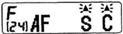
(1) With the optional-function menu, press the button above AF.
(2) Press the button corresponding to the symbol (S) or (C) for Single servo AF (AF-S) or Continuous servo AF (AF-C).
(3) Press the set/adjust button (S or C) to set the AF mode.
(4) When the menu button is pressed while the AF mode selection menu is displayed, AF mode is set to AF-S mode, and the LCD panel returns to the exposure mode menu.
(5) No AF mode setting menu is displayed.
(6) Set the focus switch at the front of the camera body to M for manual focus mode.
(7) Operation and displays in each AF mode.
| AF-M | AF-S | AF-C | |
| In-focus indicator | O | O | O |
| Out-of-focus warning | X | O | O |
| Out of focus shutter release | O | X | X |
| Focus tracking | X | O | O |
(8) When a non-AF lens is mounted, the AF mode is set to AF-M mode regardless of the focus switch position.
(9) When a non-AF lens is mounted and AF mode is set to AF-M, AF-S and AF-C modes can be set but they do not function. When AF operation becomes possible, AF-S/AF-C settings become effective.
8. Setting and confirming film speed
(1) When DX-coded film is loaded:
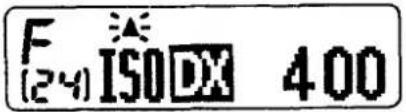
1) With the optional-function menu, press the set/adjust button corresponding to the ISO. The LCD panel shows the ISO film speed of the loaded DX-coded film.
2) When the mark ( ) above the ISO blinks and the button corresponding to the mark is pressed, the LCD panel shows the last selected exposure mode menu.
3) When the menu button is pressed while the LCD shows the ISO film speed, the LCD panel shows the exposure mode menu.
4) When using DX-coded film, film speed cannot be set.
5) Film speed range is from ISO 25 to 5000 by 1/3 Sv step.
(2) When non-DX-coded film is loaded:
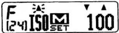
1) With the optional-function menu, press the set/adjust button corresponding to AF. The ISO setting screen is activated.
2) Press the set/adjust button corresponding to the up ( ) or down ( ) mark to adjust the film speed.
3) Press the button corresponding to the blinking ( ) mark, the ISO film speed selected can be set. The LCD panel shows the last selected exposure mode menu.
4) When the menu button is pressed while the ISO setting screen is activated, the film speed shown can be set. The LCD panel shows the exposure mode menu.
5) Film speed range is from ISO 6 to 6000 in 1/3 Sv steps.
6) When DX-coded film is loaded, the ISO film speed can be set automatically. When non-DX-coded film is loaded, the ISO setting screen appears again but the last set ISO value is displayed.
7) When non-DX-coded film is loaded, the ISO setting screen automatically appears. Until setting is completed, the shutter button remains locked, and the menu button is deactivated.
8) In item 7) above, when "Instant Jump" and "Instant Reset" are performed, the exposure mode menu to be jumped remains displayed while the button is depressed, but the ISO setting screen appears when the finger is removed from the button.
9. Exposure compensation
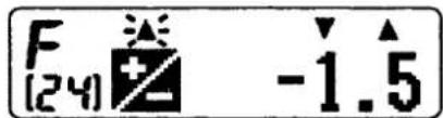
(1) With the optional-function menu, press the button corresponding to the (+/-) indication, and the exposure compensation screen appears.
(2) Set the compensation value by pressing the button corresponding to the up ( ) or down ( ) mark.
(3) Press the set/adjust buttons corresponding to the blinking ( ) mark, the compensation value can be set. The LCD panel shows the last selected exposure mode menu.
(4) When the menu button is pressed while the exposure compensation screen appears, the compensation value returns to ±0.0 and the LCD panel shows the exposure mode menu.
(5) Exposure can be compensated from -5 EV to +5 EV in 1/2 steps.
(6) When exposure is compensated, the (+/-) indication appears in the viewfinder and the LCD panel.
(7) Compensation value can be reset by returning to a ±0.0 value or when instant reset has been activated.
(8) Compensation values can be used in all exposure modes in Advanced mode. (In M mode, compensated exposure value is displayed in the analog indicator.)
(9) When shooting mode is switched over to Simple mode, the compensated exposure values set are neglected.
(10) When using flash, exposure compensation is effective for both background (AE exposure) and the main subject (exposure by TTL).
10. Instant reset
- Press the menu button and the self-timer button all together for over 2 seconds to carry out instant reset. The details of the instant reset is described as follows.
(1) In Simple mode:
The LCD panel returns to the general-purpose program mode in the programmed auto exposure mode.
(2) In Advanced mode:
Except when using non-DX-coded film, settings in the optional-function mode are returned to the basic settings, and the LCD panel returns to the general-purpose program mode in the programmed auto exposure mode.
*The basic settings in the optional-function mode: No exposure memory is set, AF mode is set to S, exposure compensation is set to ±0.0, and a change in a combination of shutter speed/aperture is released.
11. Self-timer operation

(1) Press the self-timer button then the self-timer indicator appears in the LCD panel.
(2) Self-timer mode cannot be activated when the self-timer button is pressed while the exposure mode menu or optional-function mode screen appears in the LCD panel.
(3) Press the shutter release button to start the self-timer operation while the self-timer indicator appears in the LCD panel.
(4) Press the menu button while the self-timer indicator appears in the LCD panel or the self-timer operation is being started to cancel the self-timer. The LCD panel returns to the last selected exposure mode menu.
(5) Self-timer duration is approx. 10 seconds during which the self-timer indicator in the LCD panel and the self-timer LED blinks. The self-timer LED blinks at 2Hz for the first 8 seconds and lights for the remaining 2 seconds.
(6) Exposure mode for the self-timer operation is the last exposure mode immediately before the self-timer button is pressed.
(7) After the shot, the exposure mode returns to that which preceded the self-timer shot.
(8) During the self-timer operation, the viewfinder display is activated.
(9) When the shutter release button is pressed slightly during self-timer operation, AF operation is activated.
12. AE lock
(1) Lock system
1) While the AE-L button is depressed, the BV value is locked at the time when the AE-L button is pressed. Remove the finger from the button to release the lock.
2) Exposure metering system is the same as if the AE-L button was not pressed.
3) The AE-L button is effective in all exposure modes. In M mode, the analog indicator appears based on the BV value.
4) When using flash, AE is locked against the bright background.
5) As AE is locked at the time when the self-timer is activated, no effect is observed when the AE-L button is pressed.
(2) AE lock specifications
1) In the AE lock, only the BV value is locked. Other operations perform normally.
2) If exposure mode, shutter speed, aperture, shutter speed/aperture combination, film speed, or exposure compensation are changed, the indications and controls based on the locked BV value are carried out.
3) When the wide open aperture value changes due to zooming operation, the indications and controls based on the locked BV value are carried out for the changed aperture value, except in the following cases.
- when the aperture value is at the minimum or maximum limit.
- when the program chart varies due to the change of focusing distance or wide open aperture value.
4) When the shutter speed is changed to X by using the flash while the AE-L button is pressed, the indications and controls are carried out by calculating the aperture value from the changed shutter speed and BV value.
5) When the camera enters in a warning state while AE is locked, the warning operation has priority. But the BV value is kept stored. When the warning is released, the indications and controls are carried out based on the BV value at the time when the AE was locked.
6) If self-timer operation is activated while the AE is locked, self-timer operation works based on the locked BV value.
7) If the AE-L button is pressed when the power switch is OFF or shutter pre-release timer is OFF, the BV value is locked when the shutter pre-release timer is turned ON.
13. Shutter pre-release timer
(1) Activating the shutter pre-release timer
1) While the power switch is turned ON, the shutter pre-release timer functions when:
• The shutter pre-release switch is ON.
• The menu button is ON.
• The elf-timer button is ON.
• The camera back is closed.
• The camera back is opened.
• The battery is replaced.
(2) Upgrading the shutter pre-release timer
1) The shutter pre-release timer is upgraded when:
• The shutter pre-release switch is ON.
- The menu button and set/adjust button are pressed.
• The built-in flash pops up.
2) The shutter pre-release timer does not turn OFF when:
• The self-timer is activated.
• The AE-L button is pressed.
14. Frame counter
(1) Frame counter indications: E and 1 to 99.
(2) The frame counter counts up to 99 and stays there.
(3) The frame counter counts down to E. When an error occurs during film rewinding, no E sign appears in the LCD panel.
(4) Frame counter reset Frame counter is reset to E when:
1) Camera back is opened disregarding whether the power is turned ON or OFF.
2) Camera back is closed disregarding whether the power is turned ON or OFF.
3) Film rewind operation is completed.
(5) Memory of frame counter
The contents of the frame counter are stored in the memory in the camera body and remain in memory when the battery is replaced.
Warning indication
- Warning indication screen, possible warning indication screen, operation with warning indication, reason for warning, method of releasing warning indication.
- Two warning indications are displayed both in the LCD panel and the viewfinder. One warning indication only is displayed in either the LCD panel or the viewfinder.
- If more than two warning indications are to be displayed, lower numbered warning indications have priority. But warning indications from (1) to (12) cannot be displayed more than two at a time.
• [Shaded portion]: Blinking portion.
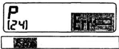
(1) Battery is exhausted.
| Simple mode | Advanced mode | |||||
| Active screen | Option screen | P | S | A | M | Option screen |
| With warning indication | With warning indication | With warning indication | With warning indication | With warning indication | With warning indication | With warning indication |
| Shutter release | AF operation | Setting operation | |||
| Menu button | Shutter speed | Aperture | Self-timer | ||
| X | X | X | X | X | X |
| Reason for the warning indication | Battery is exhausted. |
| Method of releasing the warning indication | Replace the battery. |
* This indication appears when the battery voltage drops lower than battery check level 2 stored in the EEPROM.
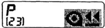
(2) Film rewind completion

| Simple mode | Advanced mode | |||||
| Active screen | Option screen | P | S | A | M | Option screen |
| With warning indication | With warning indication | With warning indication | With warning indication | With warning indication | ||
| Shutter release | AF operation | Setting operation | |||
| Menu button | Shutter speed | Aperture | Self-timer | ||
| X | O | X | X | X | X |
| Reason for the warning indication | Film rewind is complete. |
| Method of releasing the warning indication | Open the camera back. |
* This indication appears when the film is rewound completely. This indication is kept remained until the camera back is open even when the power is turned OFF or the shutter pre-release timer is turned OFF, when the power is turned ON again.
(3) Film is being rewound.
| Simple mode | Advanced mode | |||||
| Active screen | Option screen | P | S | A | M | Option screen |
| With warning indication | With warning indication | With warning indication | With warning indication | With warning indication | ||
| Shutter release | AF operation | Setting operation | |||
| Menu button | Shutter speed | Aperture | Self-timer | ||
| X | O | X | X | X | X |
| Reason for the warning indication | Film is being rewound. |
| Method of releasing the warning indication | Automatically released when the film rewind is completed. |
* This indication appears during film rewind. The indication is released when the film rewind operation is canceled.
(4) Sequence error
| Simple mode | Advanced mode | |||||
| Active screen | Option screen | P | S | A | M | Option screen |
| With warning indication | With warning indication | With warning indication | With warning indication | With warning indication | ||
| Shutter release | AF operation | Setting operation | |||
| Menu button | Shutter speed | Aperture | Self-timer | ||
| X | 0 | X | X | X | X |
| Reason for the warning indication | Sequence error occurs. |
| Method of releasing the warning indication | Turn the power switch OFF and ON. |
* This indication appears when the X contact does not turn ON during shutter release sequence operation. This means that some trouble occurs in the most previous shooting. Turn the power switch OFF and ON again to release the warning indication. Error recovery control is carried out if necessary.
Error recovery control
(1) One frame advances disregarding whether the shutter release switch is ON or OFF in the following cases.
- X contact is ON when the shutter pre-release timer is turned ON.
- The previous shutter releases interruption operation is still memorized.
- Sequence error occurrence (X contact does not turn ON, aperture pulse numbers do not reach the specified numbers) is memorized.
(2) If the previous film rewind interruption operation is memorized when the shutter pre-release timer is turned ON, film rewind operation starts whether or not the mid-roll rewind button is pressed.
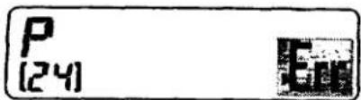
(5) Automatic film loading error
![P [ E ] Err](/content/2026/05/1131009/images/ea7b4ce697a4bbb3b686d8cb1d06ccf7e0e7bb7e7620867deebeda779426c841.jpg)
| Simple mode | Advanced mode | |||||
| Active screen | Option screen | P | S | A | M | Option screen |
| With warning indication | With warning indication | With warning indication | With warning indication | With warning indication | ||
| Shutter release | AF operation | Setting operation | |||
| Menu button | Shutter speed | Aperture | Self-timer | ||
| X | O | X | X | X | X |
| Reason for the warning indication | Malfunction in automatic film loading |
| Method of releasing the warning indication | Open the camera back (Rewind the film before opening the camera back if necessary.) |
* This indication appears when more than 3 and less than 32 sprocket pulses are emitted during automatic film loading. This indication remains until the camera back is open even when the power is turned OFF, and ON again.
(6) Film rewind error
| Simple mode | Advanced mode | |||||
| Active screen | Option screen | P | S | A | M | Option screen |
| With warning indication | With warning indication | With warning indication | With warning indication | With warning indication | ||
| Shutter release | AF operation | Setting operation | |||
| Menu button | Shutter speed | Aperture | Self-timer | ||
| X | O | X | X | X | X |
| Reason for the warning indication | Film rewind error has occurred. |
| Method of releasing the warning indication | Replace the battery, or open the camera back. |
* Film rewind operation will be completed when the sprocket pulse output interval becomes 2.5 seconds when the sprocket pulse is detected during rewinding film. In this case, if the frame counter shows "1", the operation is completed normally. If the frame counter shows "2" or more, film rewind error occurs. This indication appears when the film rewind operation becomes impossible due to exhausted battery power during film rewind. As this phenomenon is stored in memory, the film rewind operation continues through the error recovery control even when the battery is replaced. When the film rewind operation has been completed normally through the error recovery control, the warning indication is released.
When the camera back is open, the warning indication is released unconditionally.
As a special case, when the battery is removed and installed again during film rewind, the frame counter does not count down to 1, and the warning indication appears even though the film rewind operation is completed. Furthermore in this case, the warning indication cannot be released even if the power switch is turned ON or OFF to activate error recovery control because of the completion of the film rewind operation. Open the camera back to release the warning indication.
(7) Loading non-DX-coded film in Simple mode
![[ ] [ ]](/content/2026/05/1131009/images/b9aeadb2926d2fd3f0ebb4a6d15e5154d95ec0df2a34c14383e35acbd3fec4ca.jpg)
| Simple mode | Advanced mode | |||||
| Active screen | Option screen | P | S | A | M | Option screen |
| With warning indication | No warning indication | No warning indication | No warning indication | No warning indication | No warning indication | |
| Shutter release | AF operation | Setting operation | |||
| Menu button | Shutter speed | Aperture | Self-timer | ||
| X | O | X | X | X | X |
| Reason for the warning indication | Non-DX-coded film is loaded in Simple mode. |
| Method of releasing the warning indication | Replace the film with a DX-coded film. Change the Simple/Advance dial to Advance mode. |
* Non-DX-coded film cannot be used in Simple mode. Change the Simple/Advance dial to Advance mode. This warning indication appears when DX codes cannot be read due to poor DX contacts or when the wrong codes are read.
(8) Non-CPU lens is mounted or no lens is mounted. (In other than M mode)
![P [ : ] Err 100 E](/content/2026/05/1131009/images/77a9ff741a2f512001b52e523fc658e6759f40bf7d5dcda75aa7cf374edc642d.jpg)
| Simple mode | Advanced mode | |||||
| Active screen | Option screen | P | S | A | M | Option screen |
| With warning indication | With warning indication | With warning indication | With warning indication | No warning indication | ||
| Shutter release | AF operation | Setting operation | |||
| Menu button | Shutter speed | Aperture | Self-timer | ||
| X | X | O | X | X | X |
| Reason for the warning indication | Communication between the camera and the lens is impossible. |
| Method of releasing the warning indication | Use in M mode. Use a lens with CPU. |
* This warning indication appears when no communication is made between the camera and the lens. Shutter can be released in M mode.
(9) Non-CPU lens is mounted, or no lens is mounted. (In M mode)
![M [ ] 125 125 F - -](/content/2026/05/1131009/images/71a827cea5d843c0852e1e167c9c24a7243077d968b0c1b391323119deb20d96.jpg)
| Simple mode | Advanced mode | |||||
| Active screen | Option screen | P | S | A | M | Option screen |
| With warning indica-tion | No warning indica-tion | |||||
| Shutter release | AF operation | Setting operation | |||
| Menu button | Shutter speed | Aperture | Self-timer | ||
| O | X | O | O | X | O |
| Reason for the warning indication | Communication between the camera and the lens is impossible. |
| Method of releasing the warning indication | Use a lens with CPU. |
* This warning indication appears when communication between the camera and the lens is impossible. This indicates that AE does not function, although it works in M mode. Use the lens aperture ring to adjust the aperture.
(10) Minimum aperture reset error
| Simple mode | Advanced mode | |||||
| Active screen | Option screen | P | S | A | M | Option screen |
| With warning indication | No warning indication | With warning indication | With warning indication | With warning indication | With warning indication | No warning indication |
| Shutter release | AF operation | Setting operation | |||
| Menu button | Shutter speed | Aperture | Self-timer | ||
| X | 0 | 0 | X | X | X |
| Reason for the warning indication | Lens aperture ring is not set to the minimum aperture. |
| Method of releasing the warning indication | Set the lens aperture ring to the minimum aperture. |
* Make sure to set the lens aperture ring to the minimum aperture since the camera body has no aperture coupling ring. When a non-CPU lens is mounted, no communication between the body and the lens is possible, and no warning indication appears.
(11) External flash is not set to TTL mode.
E
| Simple mode | Advanced mode | |||||
| Active screen | Option screen | P | S | A | M | Option screen |
| With warning indication | No warning indication | With warning indication | With warning indication | No warning indication | No warning indication | No warning indication |
| Shutter release | AF operation | Setting operation | |||
| Menu button | Shutter speed | Aperture | Self-timer | ||
| X | 0 | O | X | X | X |
| Reason for the warning indication | Flash is not set to TTL mode when the exposure mode is set to P or S. |
| Method of releasing the warning indication | Set the exposure mode to A or M mode. Set the flash to TTL mode. |
* When the camera's exposure mode is set to P or S mode, an external flash cannot be used unless it is set to TTL mode. This is because the flash's aperture value must be identical with the camera's aperture value when using an external flash. As there is no communication capability between the camera body and the external flash, it is impossible have corresponding aperture values.
In A and M mode, it is possible for the user to read the flash's aperture value and set the camera's aperture accordingly. When the external flash is set to TTL mode and the built-in flash is used, there appears no warning indication because of the TTL flash mode.
(12) Time warning indication in S mode
| Simple mode | Advanced mode | |||||
| Active screen | Option screen | P | S | A | M | Option screen |
| With warning indication | No warning indication | |||||
| Shutter release | AF operation | Setting operation | |||
| Menu button | Shutter speed | Aperture | Self-timer | ||
| X | 0 | 0 | 0 | X | X |
| Reason for the warning indication | Shutter speed is set to Time in S mode. |
| Method of releasing the warning indication | Change the shutter speed. |
* This warning indication appears when the shutter speed is set to Time in M mode and changed to S mode while shutter speed remained set to Time. In S mode, if the shutter speed is determined first, the aperture value cannot be set, and the warning indication appears. Change the shutter speed to release the warning indication.
(13) AF does not work correctly.

| Simple mode | Advanced mode | |||||
| Active screen | Option screen | P | S | A | M | Option screen |
| With warning indication | With warning indication | With warning indication | With warning indication | With warning indication | With warning indication | With warning indication |
| Shutter release | AF operation | Setting operation | |||
| Menu button | Shutter speed | Aperture | Self-timer | ||
| X | 0 | 0 | 0 | 0 | 0 |
| Reason for the warning indication | Focusing is impossible in AF mode. |
| Method of releasing the warning indication | Use manual focus mode. Focus on another subject. |
* This warning indicator appears when focusing is impossible in AF mode. In manual focus, no warning indicator appears even when no subject is detected. Normally, the shutter is locked when this warning indicator appears. But the shutter is not locked in self-timer mode only. This warning indicator appears in combination with all other warning indicators in AF mode.
(14) No film is loaded.
![P AUTO [ E ]](/content/2026/05/1131009/images/159c5938b5d3cfd59c04a56269d8b6f7a0f9d6067fda82ed897c2ce823da189e.jpg)
| Simple mode | Advanced mode | |||||
| Active screen | Option screen | P | S | A | M | Option screen |
| With warning indication | With warning indication | With warning indication | With warning indication | With warning indication | With warning indication | With warning indication |
| Shutter release | AF operation | Setting operation | |||
| Menu button | Shutter speed | Aperture | Self-timer | ||
| 0 | 0 | 0 | 0 | 0 | 0 |
| Reason for the warning indication | Film is not yet loaded. |
| Method of releasing the warning indication | Load the film. |
* When this warning indicator appears after the film is loaded automatically, the letter "E" appears in the frame counter. Nothing is affected for other displays and functions.
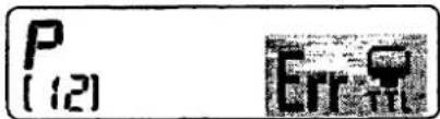
(15) Changing the combination of shutter speed/aperture
![P [12] AUTO P*](/content/2026/05/1131009/images/e2f4951731797fc2e09ff6356712fce9dc9a833459227620e9e1ed8107e0f6a1.jpg)
| Simple mode | Advanced mode | |||||
| Active screen | Option screen | P | S | A | M | Option screen |
| With warning indication | ||||||
| Shutter release | AF operation | Setting operation | |||
| Menu button | Shutter speed | Aperture | Self-timer | ||
| 0 | 0 | 0 | 0 | 0 | X |
| Reason for the warning indication | The change in shutter speed/aperture is set. |
| Method of releasing the warning indication | Release this setting. |
* In Advance mode, this warning indicator appears when you change the combination of shutter speed/aperture in the General-purpose program mode.
(16) Flash fires at full output
| Simple mode | Advanced mode | |||||
| Active screen | Option screen | P | S | A | M | Option screen |
| With warning indication | With warning indication | With warning indication | With warning indication | With warning indication | ||
| Shutter release | AF operation | Setting operation | |||
| Menu button | Shutter speed | Aperture | Self-timer | ||
| 0 | 0 | 0 | 0 | 0 | 0 |
| Reason for the warning indication | Flash fires at full output. The picture is might be underexposed. |
| Method of releasing the warning indication | Automatically released in 3 to 4 seconds. |
* When the flash fires at full output, the flash ready-light indicator ( ) blinks in the viewfinder in 3 to 4 seconds after shutter is released.
(17) Flash fires at full output
30 F2.8
| Simple mode | Advanced mode | |||||
| Active screen | Option screen | P | S | A | M | Option screen |
| With warning indication | No warning indication | With warning indication | With warning indication | With warning indication | With warning indication | No warning indication |
| Shutter release | AF operation | Setting operation | |||
| Menu button | Shutter speed | Aperture | Self-timer | ||
| 0 | 0 | 0 | 0 | 0 | 0 |
| Reason for the warning indication | Flash use is recommended due to poor light. |
| Method of releasing the warning indication | Use flash. Target the camera toward a bright subject. |
* This warning indication appears when metering value satisfies the condition of the following equation. No warning indication appears in silhouette mode.
BVM (mean metering value) + SV < 10
(18) Insufficient battery power warning
| Simple mode | Advanced mode | |||||
| Active screen | Option screen | P | S | A | M | Option screen |
| With warning indication | No warning indication | With warning indication | With warning indication | With warning indication | No warning indication | No warning indication |
| Shutter release | AF operation | Setting operation | |||
| Menu button | Shutter speed | Aperture | Self-timer | ||
| 0 | 0 | 0 | 0 | 0 | 0 |
| Reason for the warning indication | Battery power is insufficient. |
| Method of releasing the warning indication | Replace the battery. |
* This warning indication appears when the battery voltage drops below battery check level 1 stored in the EEPROM.. When the voltage has recovered, the warning indication disappears. No warning indication appears in manual exposure and in the option screen.
(19) Possibility overexposure

F22

F16
| Simple mode | Advanced mode | |||||
| Active screen | Option screen | P | S | A | M | Option screen |
| With warning indication | No warning indication | With warning indication | With warning indication | With warning indication | No warning indication | No warning indication |
| Shutter release | AF operation | Setting operation | |||
| Menu button | Shutter speed | Aperture | Self-timer | ||
| 0 | 0 | 0 | 0 | 0 | 0 |
| Reason for the warning indication | Subject is too bright exceeding the shutter speed/aperture combination range. |
| Method of releasing the warning indication | Use a slow-speed film. Use a Nikon ND filter. Choose another subject. |
* This warning indication appears when the controlled EV value exceeds the upper range of the combination of shutter speed/aperture. In manual exposure mode, the analog indicator appears in the viewfinder with no warning indication. No warning indication appears when the controlled EV value is within the range of the combination of shutter speed/aperture, even though out of the metering range. The controlled EV value is determined as close to the correct exposure value as possible. But the possibility of error becomes greater and correct exposure value is not guaranteed.
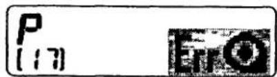
(20) Possibility underexposure
![P AUTO [17] Lo](/content/2026/05/1131009/images/e04f2c2b8e7e690bf19e89e43129dec84f580bedfd7b279044a1f4bf5c50c8ed.jpg)
L6 F 1.8
F2.8
| Simple mode | Advanced mode | |||||
| Active screen | Option screen | P | S | A | M | Option screen |
| With warning indication | No warning indication | With warning indication | With warning indication | With warning indication | No warning indication | No warning indication |
| Shutter release | AF operation | Setting operation | |||
| Menu button | Shutter speed | Aperture | Self-timer | ||
| 0 | 0 | 0 | 0 | 0 | 0 |
| Reason for the warning indication | Subject is too dark exceeding the shutter speed/aperture combination range. |
| Method of releasing the warning indication | Use flash. Use a high-speed film.Choose another subject. |
* This warning indication appears when the controlled EV value exceeds the lowest range of the combination of shutter speed/aperture. In manual exposure mode, the analog indicator appears in the viewfinder with no warning indication.
No warning indication appears when the controlled EV value is within the range of the combination of shutter speed/aperture, even though out of the metering range. The controlled EV value is determined as close to the correct exposure value as possible. But the possibility of error becomes greater and correct exposure value is not guaranteed.
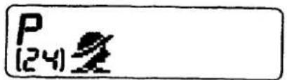
(21) Camera shake • Simple mode
flowchart
graph TD
    A["AUTO Camera Icon"] --> B["Blank Display Icon"]
    C["["]] --> D["["]]
    style A fill:#f9f,stroke:#333
    style B fill:#ccf,stroke:#333
    style C fill:#cfc,stroke:#333
    style D fill:#fcc,stroke:#333
- Advanced mode
| Simple mode | Advanced mode | |||||
| Active screen | Option screen | P | S | A | M | Option screen |
| With warning indication | No warning indication | With warning indication | No warning indication | With warning indication | No warning indication | No warning indication |
| Shutter release | AF operation | Setting operation | |||
| Menu button | Shutter speed | Aperture | Self-timer | ||
| 0 | 0 | 0 | 0 | 0 | 0 |
| Reason for the warning indication | Camera shake may occur. |
| Method of releasing the warning indication | Use flash. Change the subject. |
* This warning indicator appears when the shutter speed satisfies the following conditions. In shutter-priority auto or M exposure mode, no warning indication appears since the shutter speed is set by the user himself. Indications in the viewfinder differ depending on whether Simple mode or Advanced mode are in use.
(1) Shutter speed is slower than 1/30 sec.
(2) Shutter speed is between 1/30 sec. and 1/500 sec., and slower than 1/f sec.
(3) Decision is made not on the controlled value but on the displayed value.
| 作成承認印 | 配布許可印 |
 |
Nikon F50
FAA29051
F50D
FAA29251
N50
FAA29151
REPAIR MANUAL
修理指針
Nikon
NIKON CORPORATION
Tokyo, Japan
© Copyright 1994
ALL RIGHTS RESERVED
無断転載を禁ず!!
DISASSEMBLING
1. Separating the front body and the rear body
Hand grip front cover, Battery chamber cover D1
Bottom cover, Camera back D2
Top cover
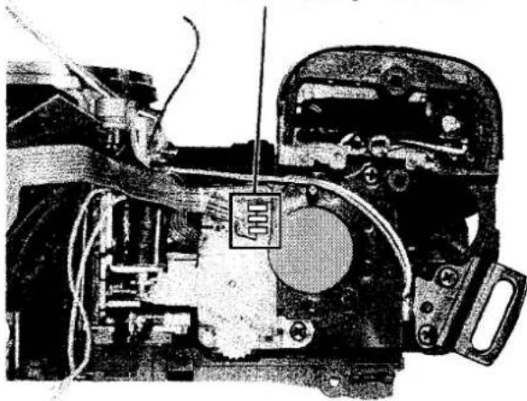
- Removing screws D2
- Discharging of the main condenser D 2
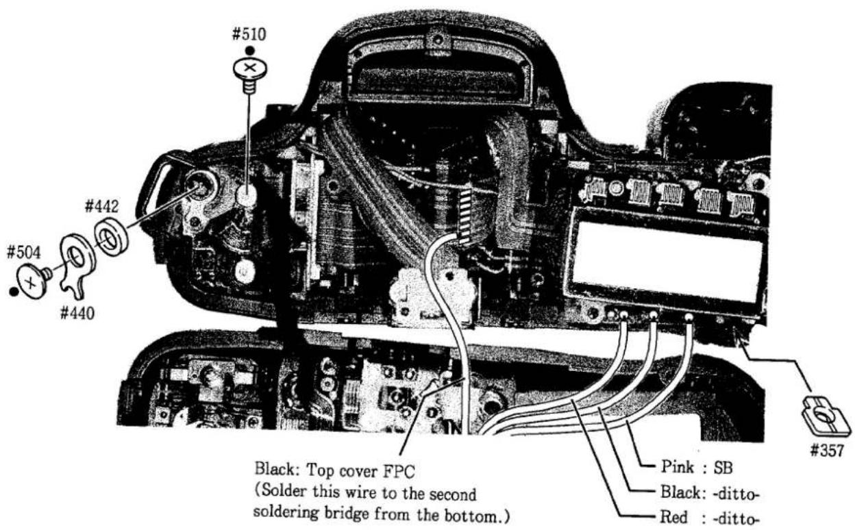
- Removing wires and press-contact D 3
Front cover, Camera back lock release, Hand grip rear cover D3
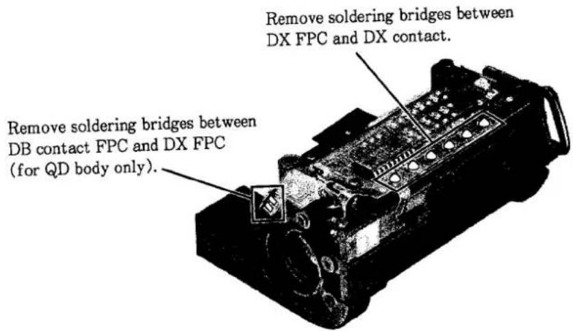
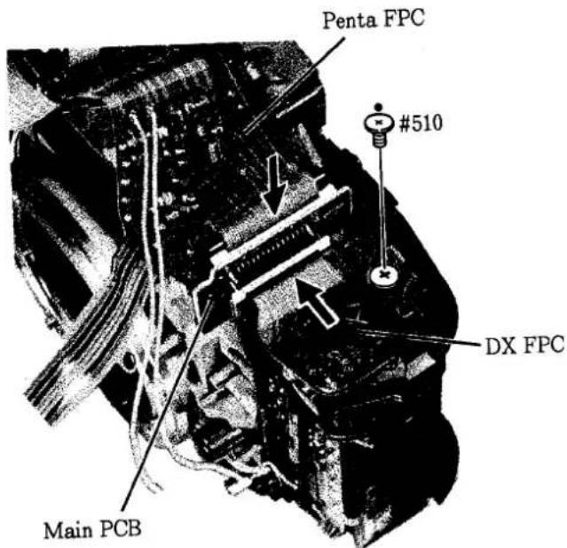
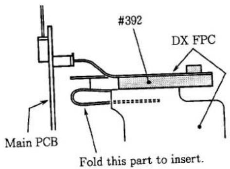
Remove wires on the DX FPC D 4
Penta FPC group
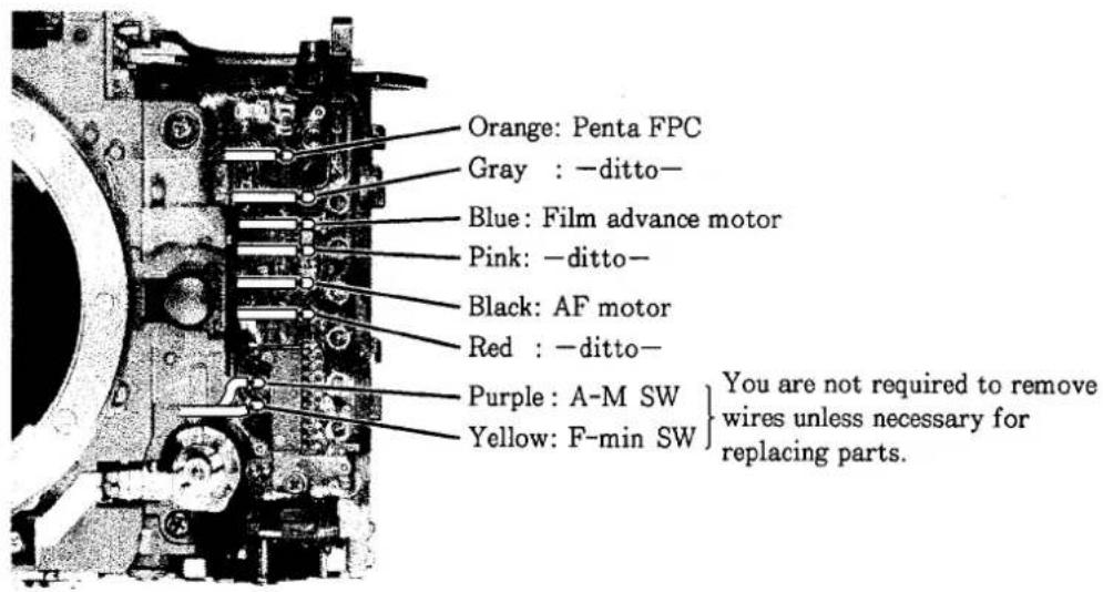
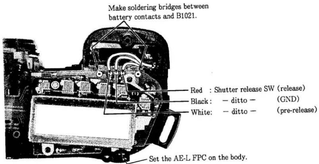
- Removing wires and soldering bridges D4
- Removing screws D4
- Removing wires and soldering bridges D5
- Disconnecting connectors D5
- Removing penta FPC group D 5
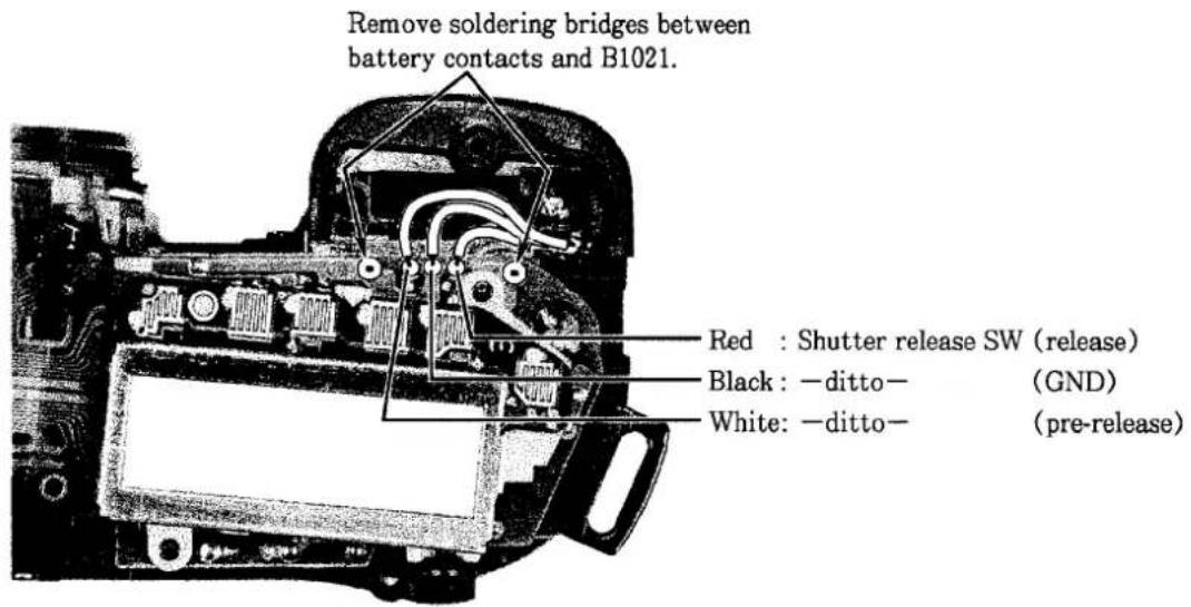
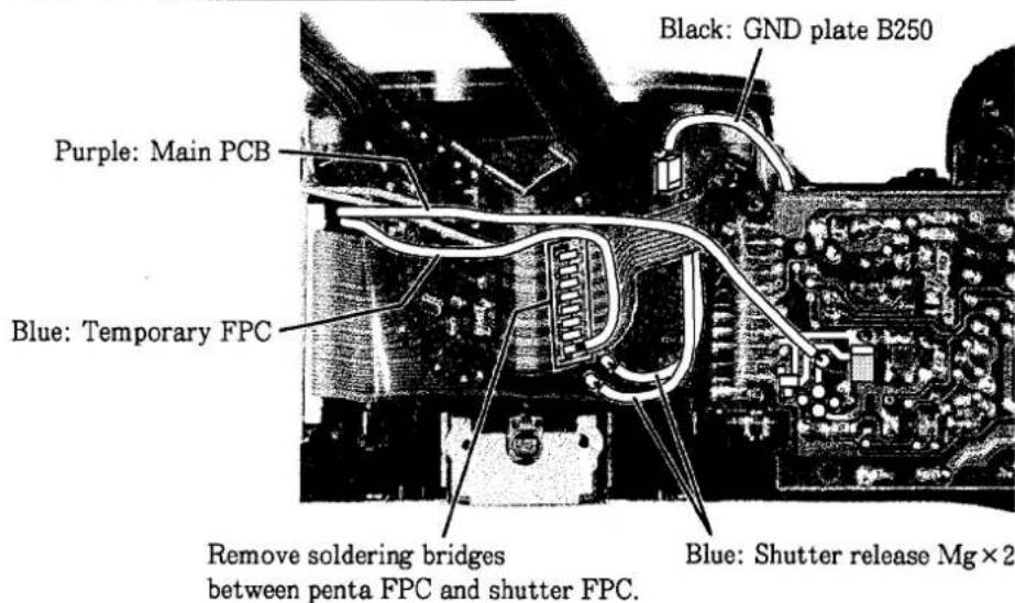
Removing soldering bridges D6
Film rewind fork group D6
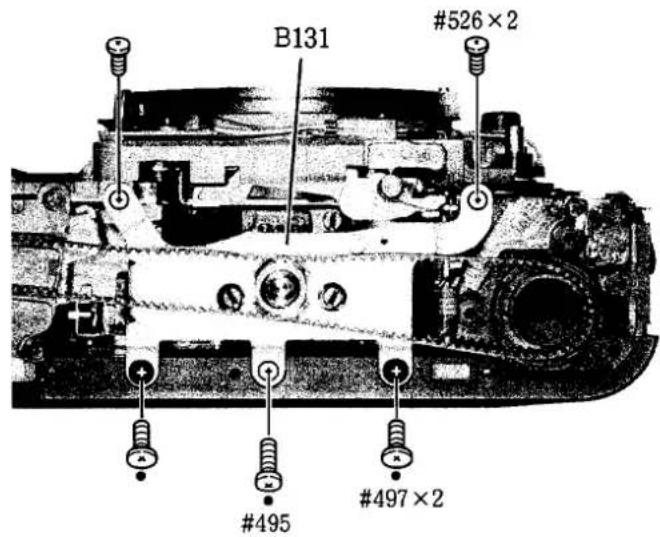
Tripod base plate B131 D 6
Film advance mechanism group D7
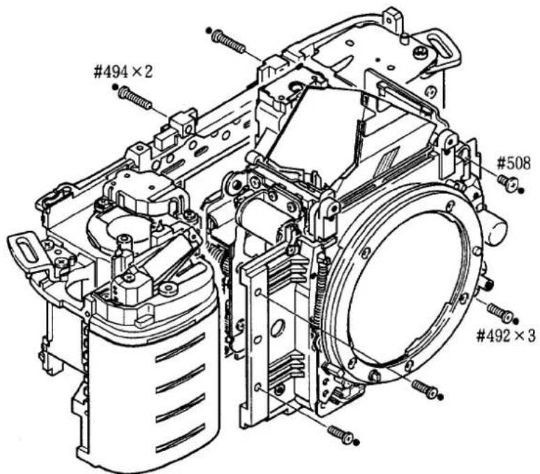
Separating front body and rear body D7
2. FRONT BODY
Shutter unit B31 D8
Main PCB D8
Aperture control unit B2251 D 9
Mirror box & pentaprism group D 9
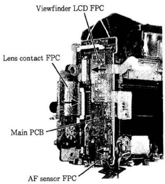
Light baffle plate, Viewfinder LCD FPC D 9
TTL FPC, AF sensor unit D10
Pentaprism group D10
Mirror box group D11
AF driving group D11
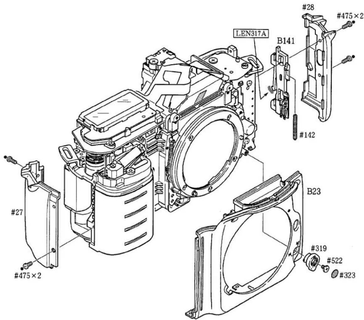
Lens mount group D12
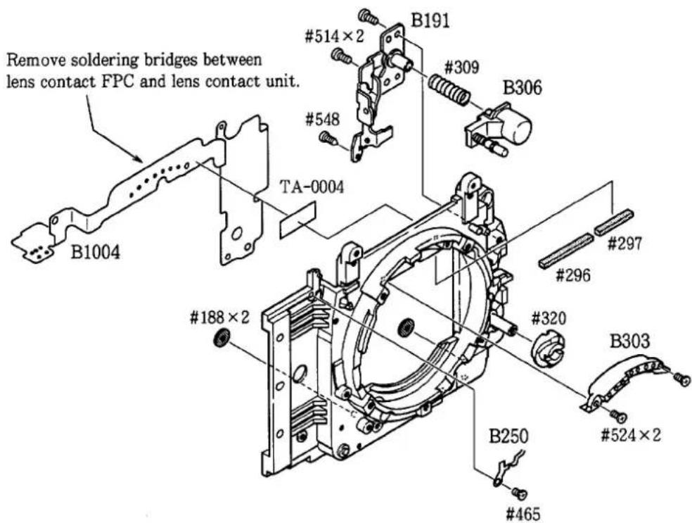
Lens contact FPC, Small parts of front body D12
3. REAR BODY
Each part on the film cartridge chamber side D13
Each part on the spool chamber side D14
Inspection standard
- Set the output voltage to 5.6V and use a 0.8Ω resistor when using a DC regulated power supply.
| Inspection item | Standard | Remarks |
| Shutter accuracy(1) Allowance(2) Difference(3) Shutter curtain | 1/2000 to 1/1500 sec.: ±0.45 SV1/1000 to 1/180 sec.: ±0.3 SV1/125 sec.: 0 to +0.3 SV1/90 to 30 sec.: ±0.3 SV1/2000 to 1/180 sec.: within 0.45 SV1/125 to 30 sec.: within 0.3 SVNo bounce is detected. | Exposure mode: M, SShutter tester (EF-8000) |
| Exposure accuracy(1) Allowance(2) Difference | 1/2000 to 1/125 sec.: ±0.65 EV1/90 to 30 sec.: ±0.5 EVWithin 0.5 EV | Exposure mode: P, A, SShutter tester (EF-8000) |
| Aperture control accuracy(1) Allowance(2) Difference | LV12 (ISO100)、1/60f/5.6: ±0.5 AVOther aperture: ±0.65 AVWithin 0.5 AV | Exposure mode: SShutter tester (EF-8000) |
| AF adjustment accuracy(1) Yaw(2) Pitch(3) Z | ±6 mrad±6 mrad±50 μm | Personal computer andother dedicated tools |
| Height of aperture lever | 3.4 ±0.1mm | J18004 |
| Main mirror 45° | Adjustment of infinity: ±0.05mmHorizontal: ±20'Distortion: ±8' | J18010J19002, J18197, J18196Optical parallelHexagonal key |
| Sub mirror 45° | Horizontal: ±20'Distortion: ±8' | |
| M. B. F. | Standard: 46.67±0.03mmParallel: Within 0.03mm | J18001Dial gauge |
| Battery check voltage(1) First level(2) Second level | 4.9V4.7V | Use a DC regulated powersupply with no resistor. |
D. 1950
than one second): Less than 400mA·sec.
D. 1950
DISASSEMBLING
Notes:
① In the assembling and disassembling sections of this manual, we took an initially produced bodies as a model to explain wiring. Wiring are subject to change depending on the period of production and may not conform with the current products. Refer to the actual model.
② As for addition and modification of parts, refer to the Technical Information bulletins already issued.
③ Be sure to remove batteries before disassembling.
④ When disassembling, pay attention to the arrangement and mounting positions and types of screw to be removed.
⑤ Be sure you are grounded when holding FPC because static electricity exerts serious adverse effects on ICs.
⑥ The “●” mark on the screws indicates they tap-tight screws.
⑦ When you disassemble the camera body further than described in the disassembling section, refer to the exploded drawings and assembling section, since some parts are disassembled as a unit part.
1. Separating the front body and the rear body
HAND GRIP FRONT COVER, BATTERY CHAMBER COVER
BOTTOM COVER, CAMERA BACK
TOP COVER
- Removing screws
- Discharging of the main ondenser
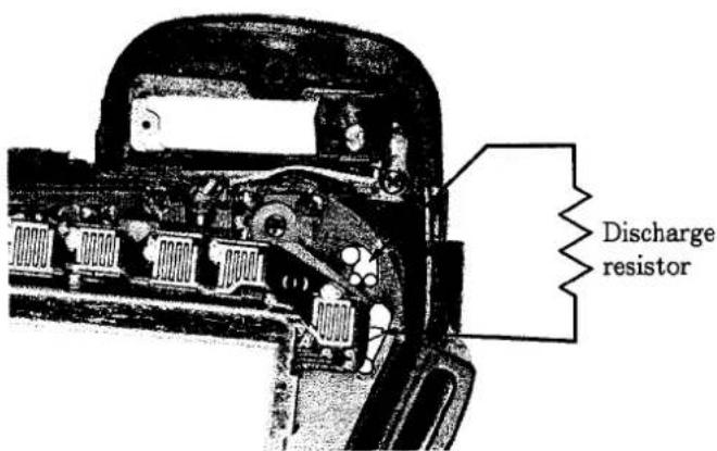
● Discharge the main condenser which is located the patterns as shown in the picture.
- Use a discharge resistor of approx. 2KΩ/5W.
- Removing wires and press-contact
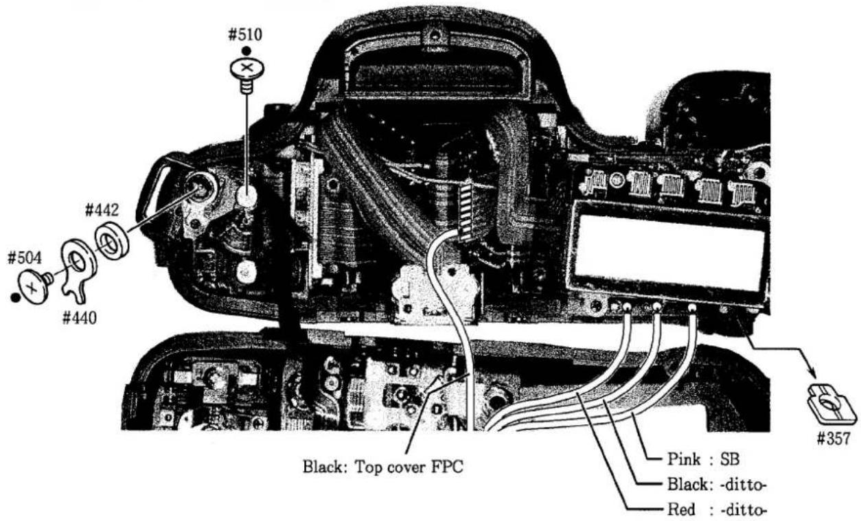
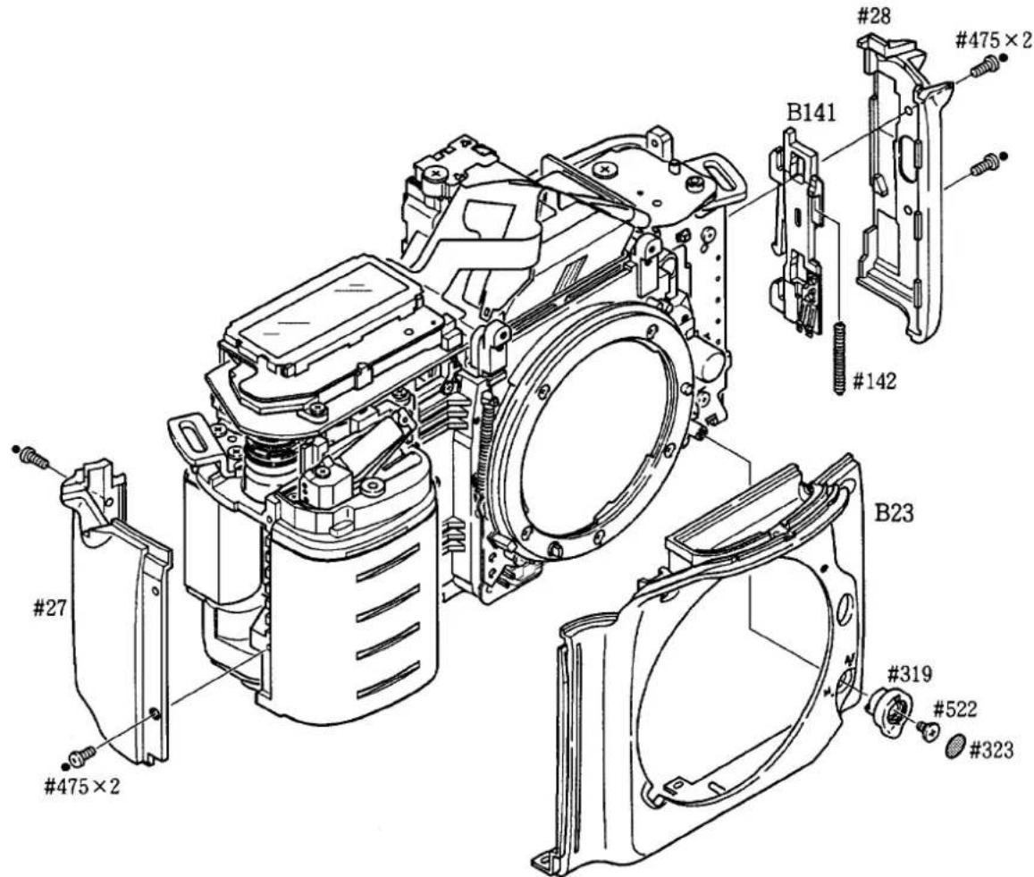
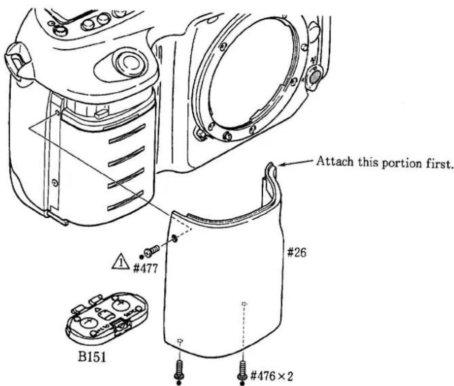
FRONT COVER, CAMERA BACK LOCK RELEASE, HAND GRIP REAR COVER
REMOVE WIRES ON THE DX FPC
PENTA FPC GROUP
1. Removing wires and soldering bridges
2. Removing screws
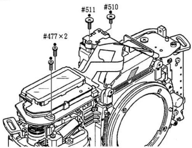
3. Removing wires and soldering bridges
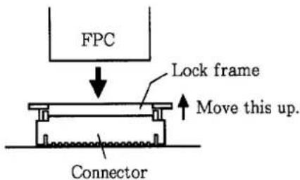
4. Disconnecting connectors
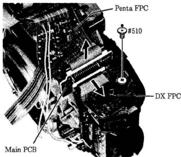
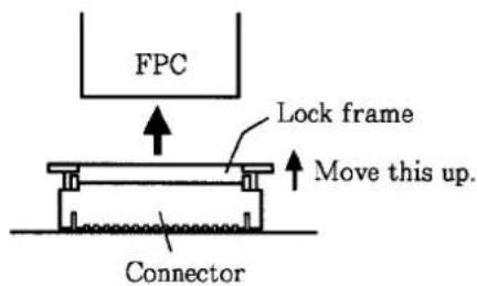
① Move up the lock frame.
Note: Do not lift the lock frame forcefully as it may become disconnected from the connector.
② Pull out FPC out of the connector.
5. Removing penta FPC group
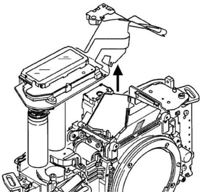
natural_image
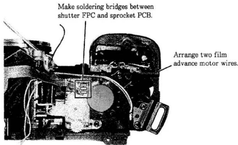
Technical line drawing of a mechanical assembly with no visible text or symbolsREMOVING SOLDERING BRIDGES
Remove soldering bridges between shutter FPC and sprocket PCB.
natural_image
Interior view of a mechanical device showing internal components and wiring (no visible text or symbols)FILM REWIND FORK GROUP
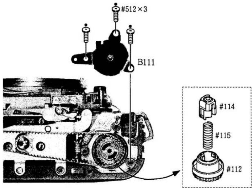
TRIPOD BASE PLATE B131
FILM ADVANCE MECHANISM GROUP
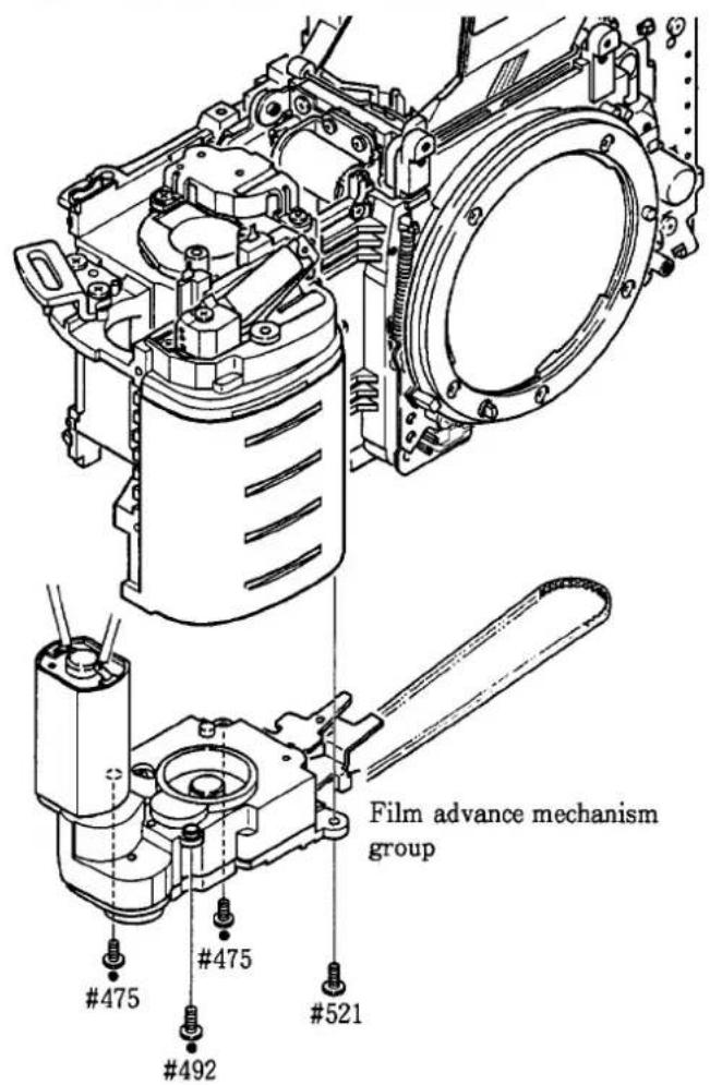
● Take care not to damage wires of film advance motor.
SEPARATING FRONT BODY AND REAR BODY
● Take care not to damage FPCs and wires.
2. FRONT BODY
SHUTTER UNIT B31
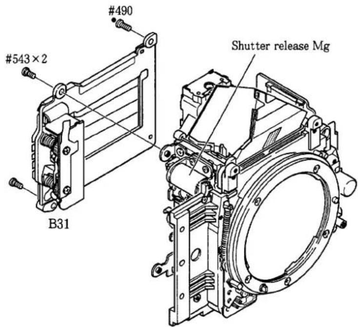
Note: Push the iron core of shutter release Mg to move up the main mirror. Then remove the shutter unit.
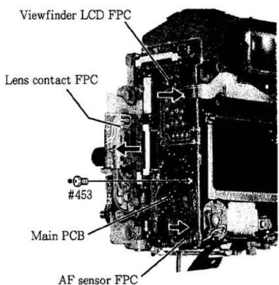
MAIN PCB
① Remove press-contact.
② Pull out FPC out of the connector.
③ Remove screw #453 and take out the main PCB.
APERTURE CONTROL UNIT B2251
MIRROR BOX & PENTAPRISM GROUP
LIGHT BAFFLE PLATE, VIEWFINDER LCD FPC
TTL FPC, AF SENSOR UNIT
PENTAPRISM GROUP
MIRROR BOX GROUP
AF DRIVING GROUP
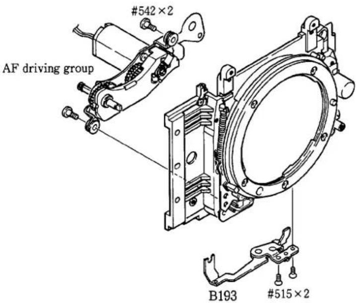
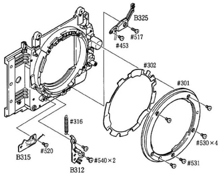
LENS MOUNT GROUP
LENS CONTACT FPC, SMALL PARTS OF FRONT BODY
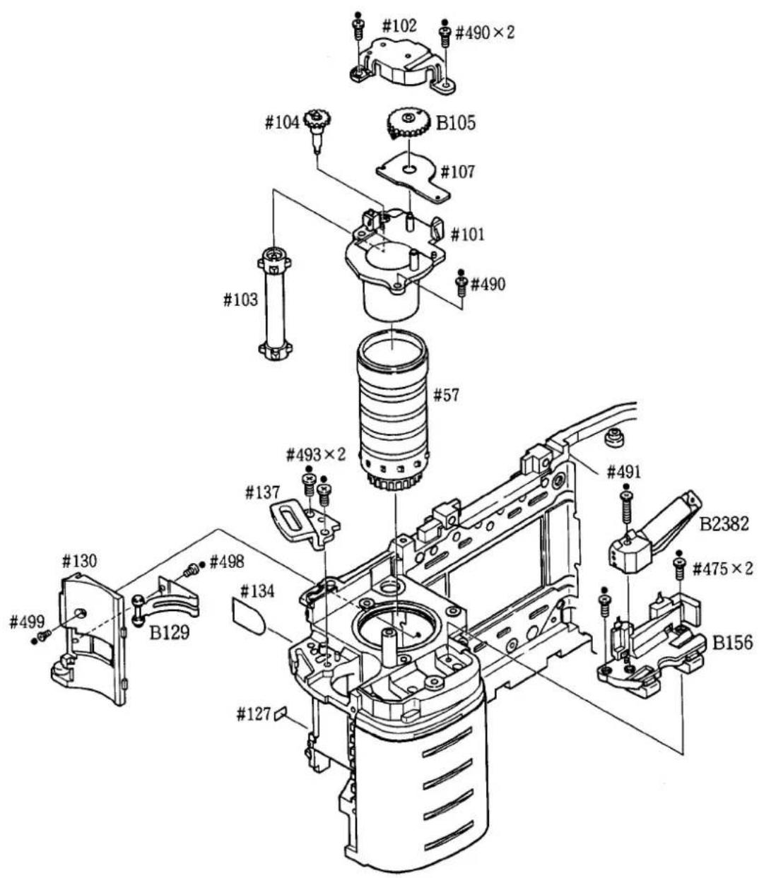
3. REAR BODY
EACH PART ON THE FILM CARTRIDGE CHAMBER SIDE
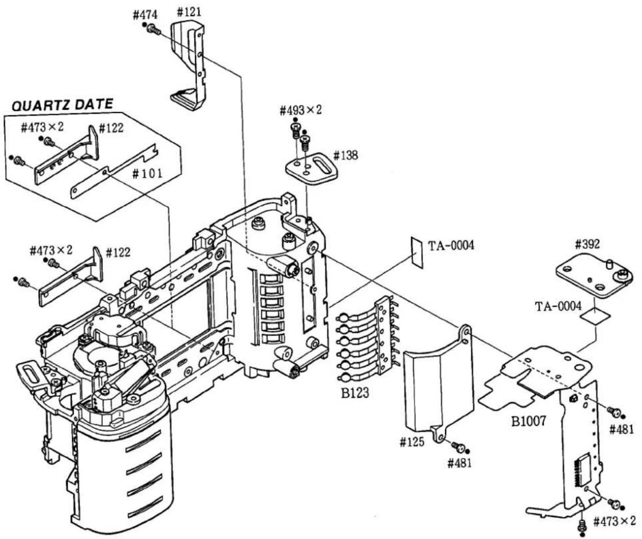
EACH PART ON THE SPOOL CHAMBER SIDE
ASSEMBLING
1. FRONT BODY
Small parts of front body A1
AF driving unit A1
Lens contact FPC A 2
Mirror box group
- Pasting main mirror A 2
- Attaching position of #228 A 2
- Mounting shutter release Mg #34 on the I base plate A 3
- Hooking springs on the I base plate A 3
- Prism box unit A 4
- Assembling mirror box A4
- Hooking springs #207, Applying grease A 5
- Attaching TTL FPC A 5
- Mounting mirror box A 6
Lens mount group A 6
Height adjustment of AF coupling shaft #184 A 7
Adjustment of aperture position A7
Angle adjustment of main mirror and sub mirror to 45° A8
Aperture control unit B2251 A 9
Pentaprism group A10
Adjustment of infinity ( ) A10
Viewfinder LCD FPC, AF sensor unit, Main PCB
- Mounting each part A11
- Connecting connectors A11
- Press-contact, Arrange wires A12
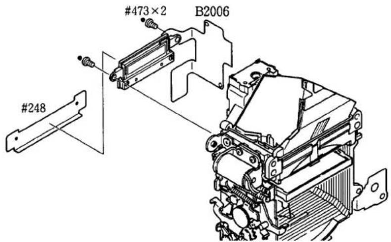
Light baffle plate #248 A12
Shutter unit, GND plate A12
2. REAR BODY
Mounting of each part on the spool chamber side A13
Mounting of each part on the film cartridge chamber side A14
ASSEMBLING & ADJUSTMENT
1. FRONT BODY
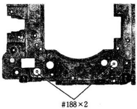
SMALL PARTS OF FRONT BODY
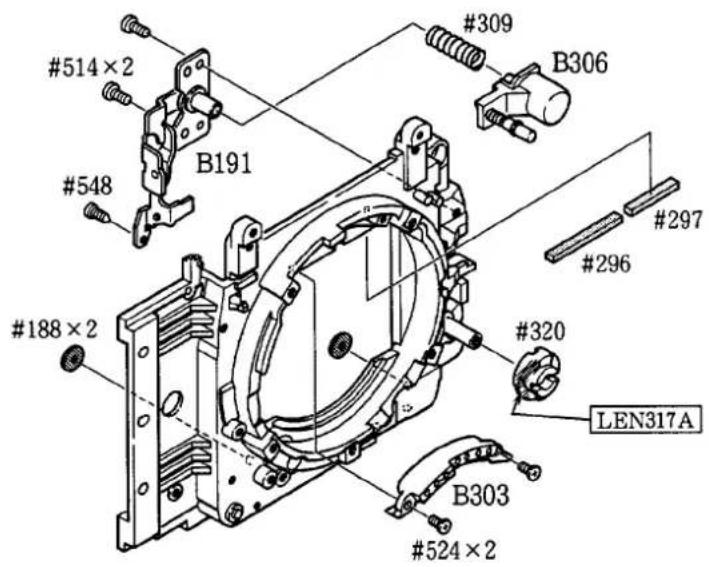
Attaching positions of #188×2
AF DRIVING UNIT
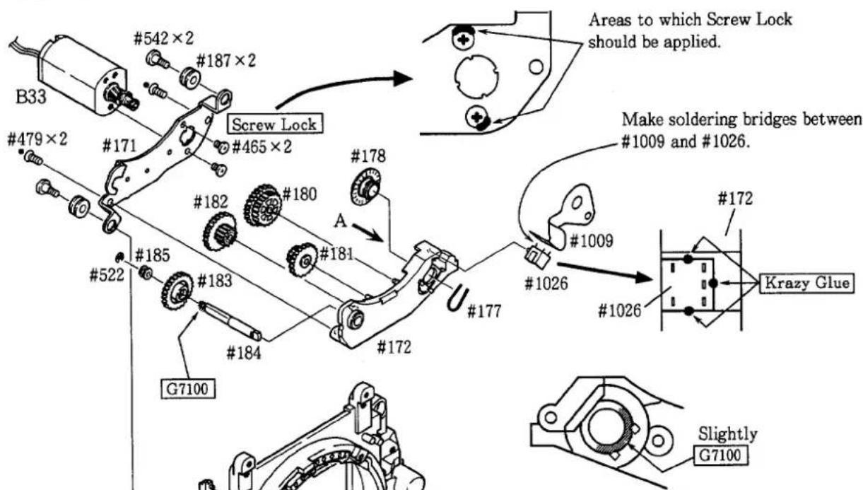
Fig. A #172 arrow indicator
- Apply slightly grease G7100 to each gear and gear shaft.
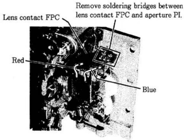
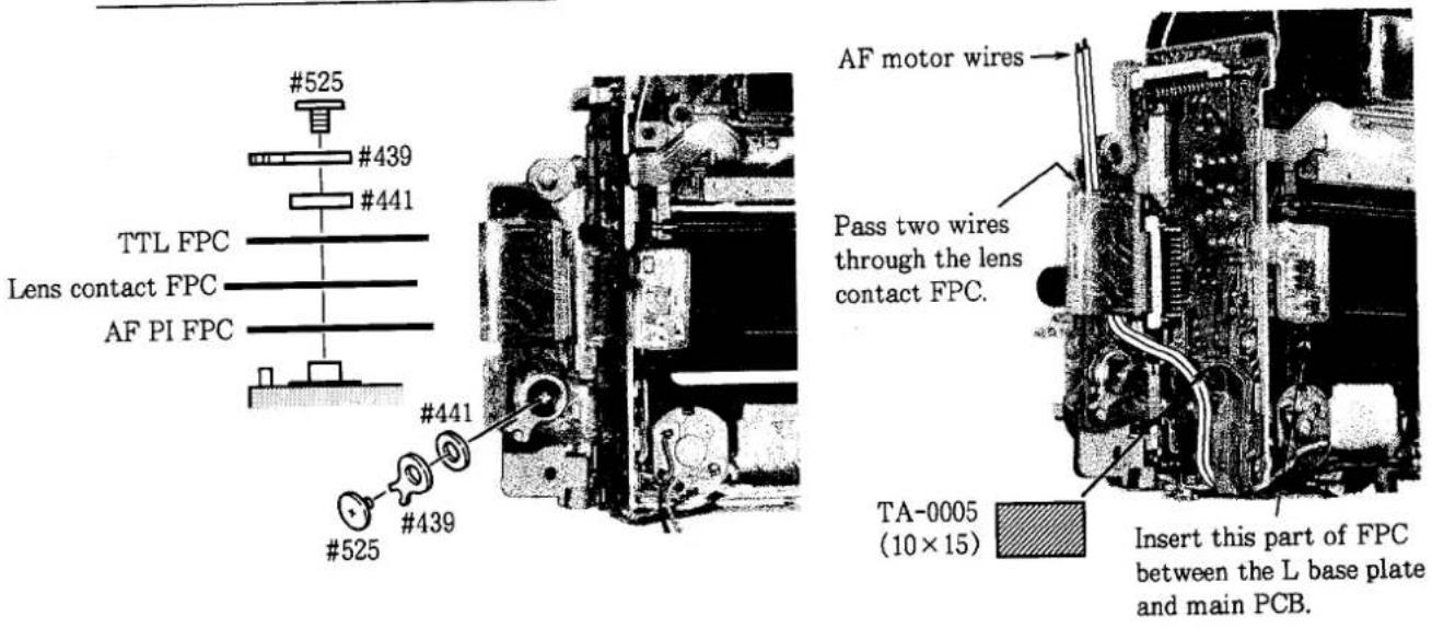
LENS CONTACT FPC
Make soldering bridges between
lens contact FPC and lens contact unit.
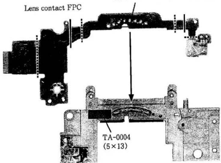
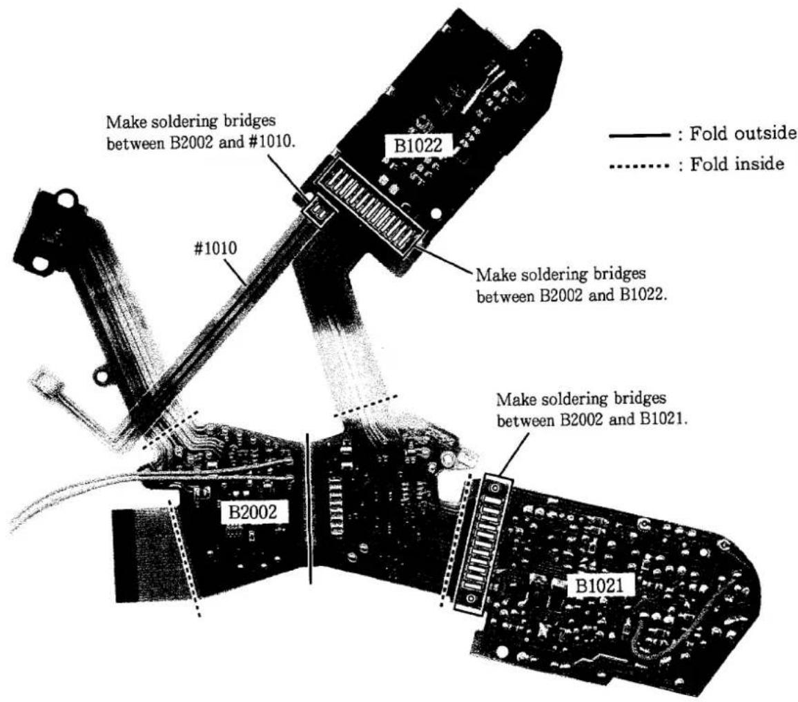
— : Fold outside
……: Fold inside
MIRROR BOX GROUP
1. Pasting main mirror
2. Attaching position of #228
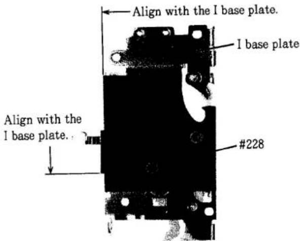

3. Mounting shutter release Mg #34 on the I base plate
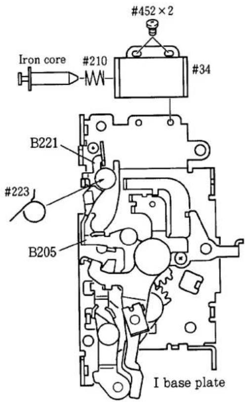
①Mount spring #223 on the I base plate.
② Pull out the iron core of shutter release Mg #34 and mount spring #210.
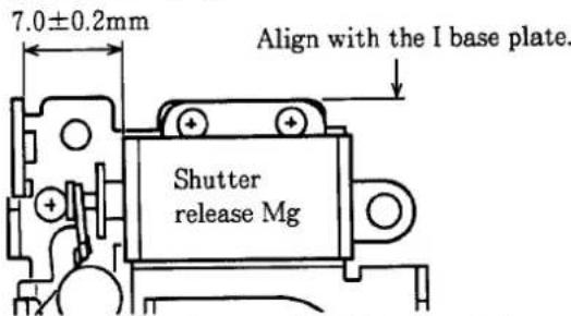
③ Secure the shutter release Mg at the location shown in the figure below using screws #452×2.
④ Rotate the eccentric pin to adjust the gap between the base plate of shutter release Mg and the iron core to 1.1 ± 0.1 mm.
Attention: Be sure that lever B221 comes into contact with the stopper of I base plate. If not, adjust the position of the shutter release Mg to be 1.1 ± 0.1 mm.
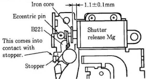
⑤ Lever B205 does not come into contact with lever B221 when moving lever B205 while fully pushing the iron core of shutter release Mg.
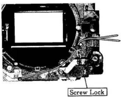
⑥ Secure screws #452×2 using Screw Lock.
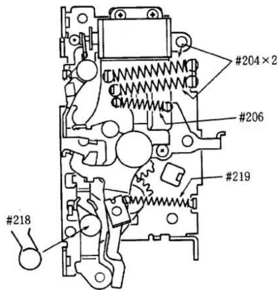
4. Hooking springs on the I base plate
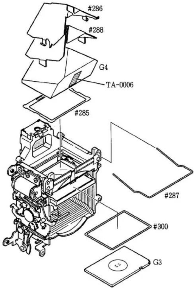
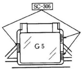
5. Prism box unit
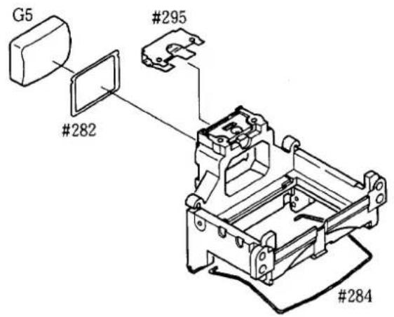
● Pasting eyepiece lens G5
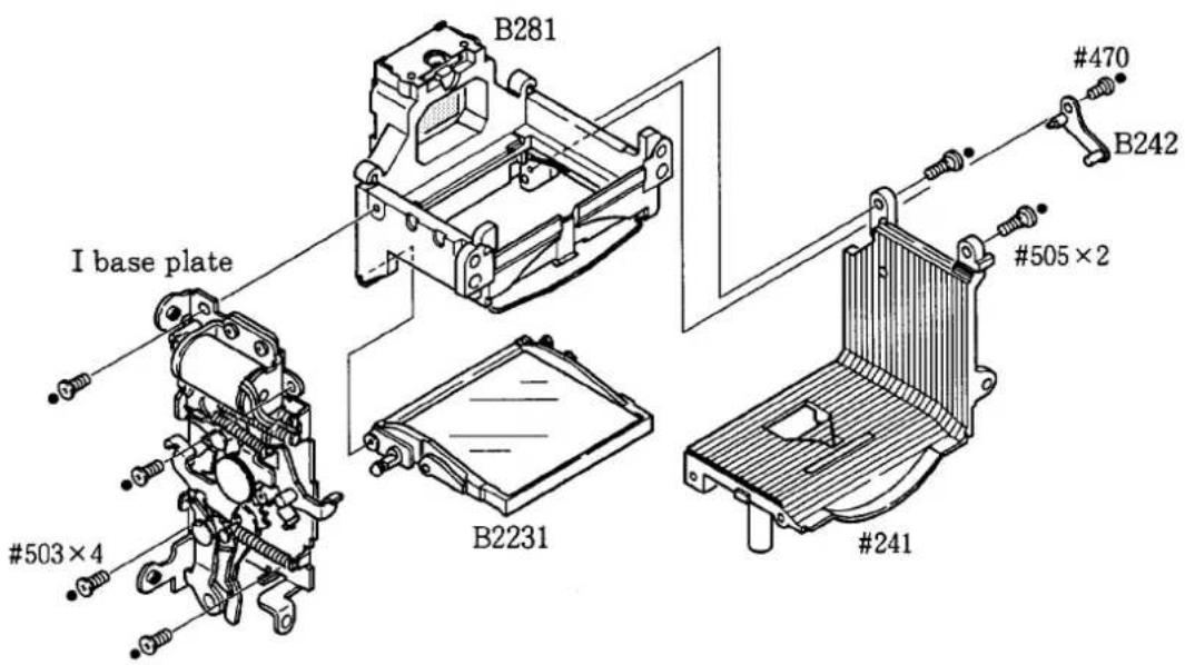
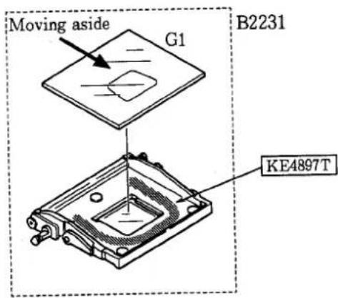
6. Assembling mirror box
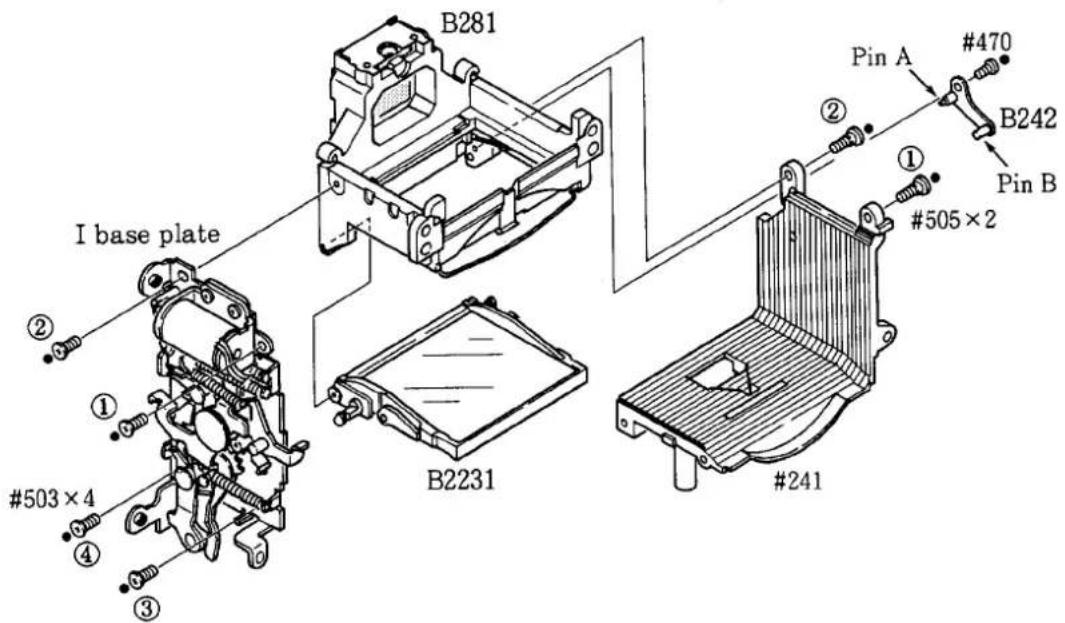
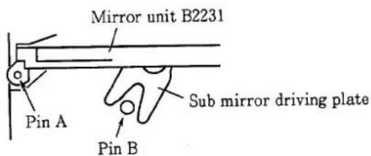
①Mount the mirror unit B2231 on the pin of prism box unit B281.
② Mount the L base plate #241 using screws #505×2. Fasten screws #505×2 in the order from ① to ②.
③ Attach the mirror shaft unit B242 using screw #470.
④ Mount the I base plate using screws #503×4. Fasten screws #503×4 in the order from ① to ④.
7. Hooking spring #207, Applying grease
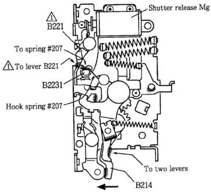
● : Apply grease LEN317A to slanting line portions.
Inspection: Make sure that main mirror moves up when pushing the iron core of shutter release Mg. Take care not to scratch the surface of main mirror. Make sure that the main mirror moves down when lever B214 is moved in the direction of arrow.
8. Attaching TTL FPC
Hold it down.
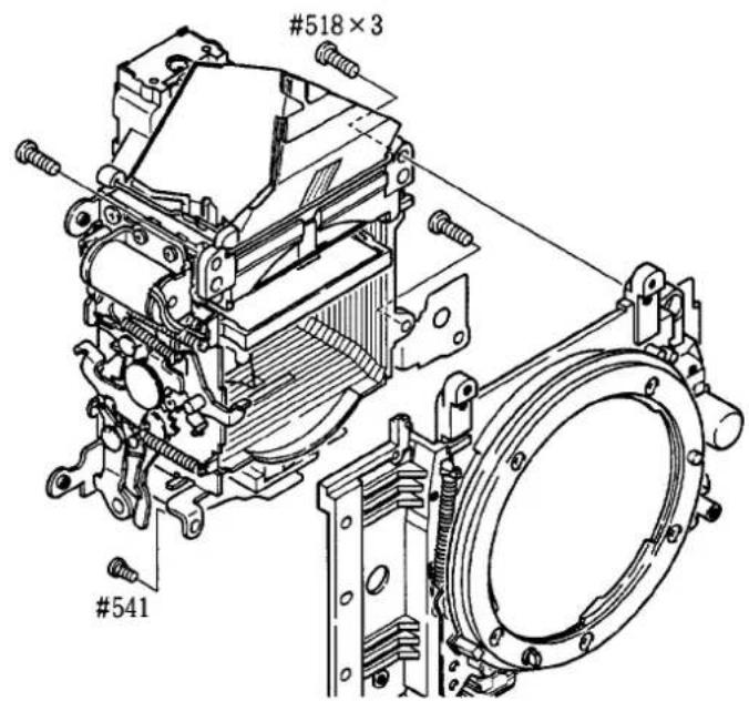
9. Mounting mirror box
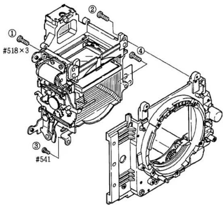
- Fasten screws #518×3 and #541 in the order from ① to ④.
LENS MOUNT GROUP
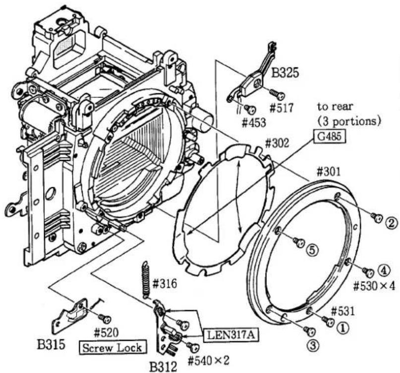
Arrange wires
- Fasten screws #530×3 and #531 in the order from ① to ④.
HEIGHT ADJUSTMENT OF AF COUPLING SHAFT #184
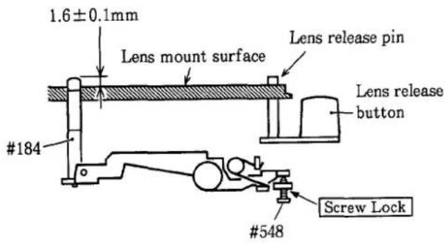
① Set the focus mode cam #320 to "AF". Measure the height of the AF coupling shaft
184 after pressing the lens release button
several times.
② Adjust the height of the AF coupling shaft using screw #548.
③ The AF coupling shaft should not protrude over the lens mount surface, when the height of lens release pin is adjusted to 0.4mm.
④ After adjusting, secure screw #548 with Screw Lock.
ADJUSTMENT OF APERTURE LEVER POSITION
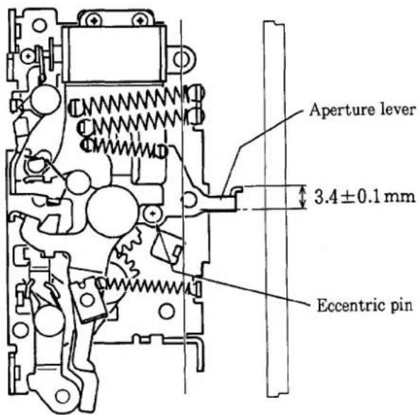
- Set each lever of the I base plate as shown in the figure.
Measure the height of the aperture lever using tool J18004. If the value is out of the standard value, rotate the eccentric pin to adjust it.
Standard value: 3.4±0.1mm
ANGLE ADJUSTMENT OF MAIN MIRROR AND SUB MIRROR TO 45°
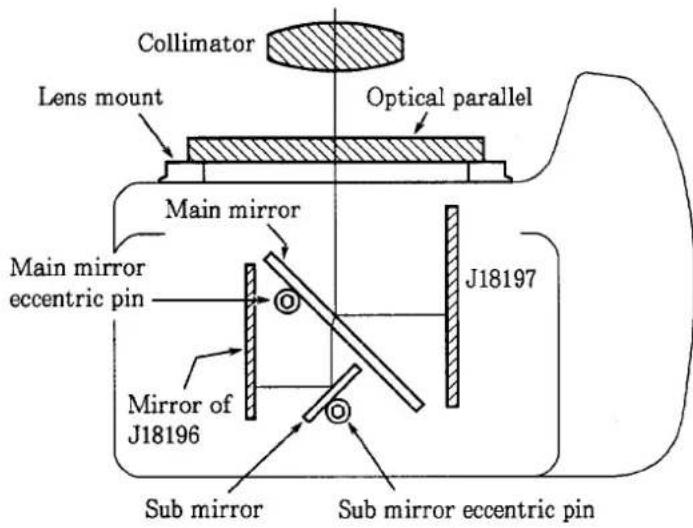
\*Use tools
- Angle adjustment of main mirror
① Collimator (J19002)
② Mirror angle inspection mirror (J18197)
③ Optical parallel
④ Hexagonal wrench
- Angle adjustment of sub mirror
① Collimator (J19002)
② Sub mirror angle adjustment tool (J18196)
③ Hexagonal wrench
- Angle adjustment of main mirror to 45^
Note: Check to confirm the accuracy of the main mirror before and after adjustment by moving it up and down several times.
① Checking the discrepancy (right/left)
If horizontal displacement is out of the standard value, it is possible that bayonet spring #302 is pinched, mirror unit B2231 is defective, or mirror shaft is bent.
② Checking the discrepancy (up/down)
If the amount of the discrepancy is out of the standard value, rotate the main mirror eccentric pin to adjust.
- Angle adjustment of sub mirror to 45^
Note: Check to confirm the accuracy of the main mirror before and after adjustment by moving it up and down several times.
① Checking the discrepancy (up/down)
If the amount of the discrepancy is out of the standard value, rotate the sub mirror eccentric pin to adjust.
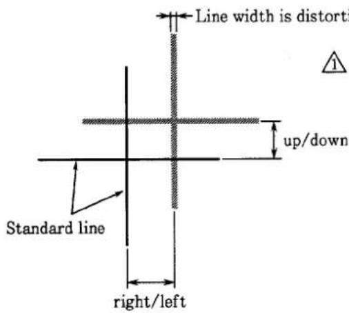

Standard:
| Main mirror | Sub mirror | |
| Discrepancy (right/left) | Within ± 20' | |
| Discrepancy (up/down) | Within ± 5' | Within ± 10' |
| Distortion | Within ± 4' | Within ± 4' |

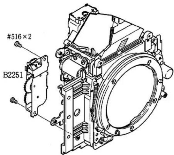
APERTURE CONTROL UNIT B2251
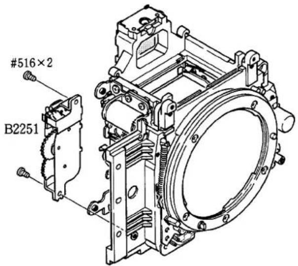
① Check to confirm that the gap between the ratchet gear of aperture control unit B2251 and the latch lever is 0.3 ± 0.1 mm.
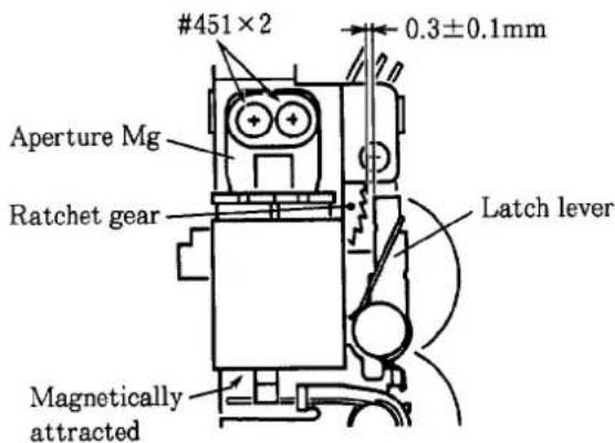
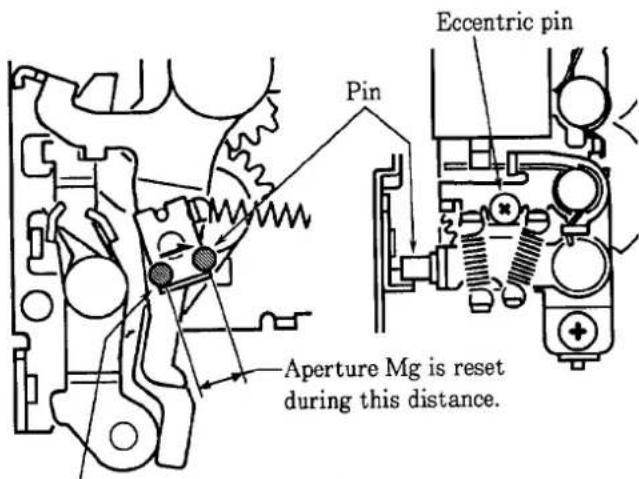
This portion moves smoothly.
Unfasten screws #451×2 and move the aperture Mg to adjust. After adjusting, secure screws #451×2 using Screw Lock.
② Mount the aperture control unit using screws #516×2.
Note: Make sure that main mirror is being moved down.
③ Rotate the eccentric pin to adjust so that the aperture Mg is reset at the location shown in the figure on the left.
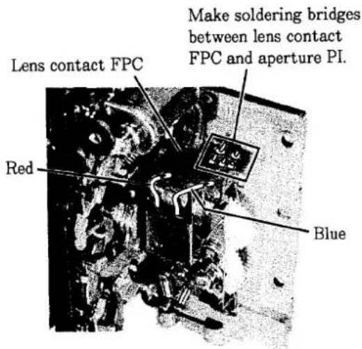
④ Solder two wires from aperture PI and the soldering bridges (between lens contact FPC and aperture PI).
PENTAPRISM GROUP
ADJUSTMENT OF INFINITY ( )
- Make the following adjustment using reference lens J18010 so that the infinity ( ) coincidence comes within the range of ± 0.05mm .
① Make coarse adjustment using spacer #300.
② Rotate the main mirror eccentric pin in the mirror box to fine adjust. Do not rotate the eccentric pin if the infinity coincidence comes within the standard range by the adjustment “①” above.
VIEWFINDER LCD FPC, AF SENSOR UNIT, MAIN PCB
- Mounting each part
- Connecting connectors
● How to connect connectors.
① Move up the lock frame.
Note: Do not lift the lock frame forcefully as it may become disconnected from the connector.
② Insert FPC into the connector. The FPC must be flat.
③ Move down the lock frame and lock the FPC.
- Press-contact, Arrange wires
LIGHT BAFFLE PLATE #248
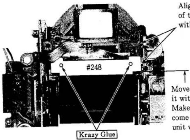
Align the horizontal position of the light baffle plate #248 with the pentaprism box.
Move up the main mirror and align it with part R of mirror unit. Make sure that main mirror does not come into contact with the mirror unit when moving up and down.
SHUTTER UNIT, GND PLATE
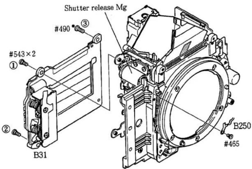
- Push the iron core of shutter release Mg to move up the main mirror. Then mount the shutter unit.
- Fasten screws #543×2 and #490 in the order from ① to ③.
2. REAR BODY
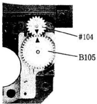
MOUNTING OF EACH PART ON THE SPOOL CHAMBER SIDE
- Marks “▲” of gear #104 and B105 should be aligned.
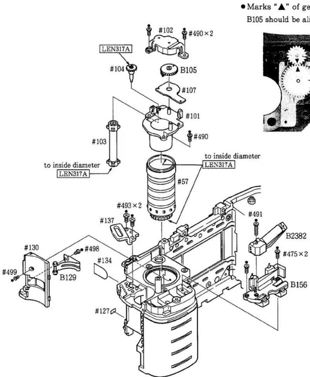
MOUNTING OF EACH PART ON THE FILM CARTRIDGE CHAMBER SIDE

3. FRONT BODY & REAR BODY
MOUNT FRONT BODY ON REAR BODY
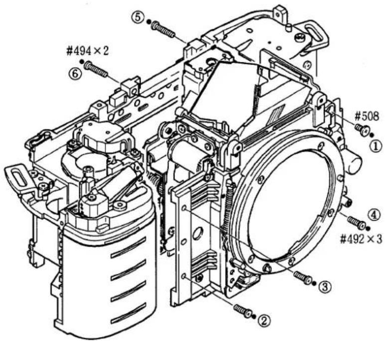
● Take care not to damage FPCs and wires.
- Fasten screws in the order from ① to ⑥.
FILM ADVANCE MECHANISM GROUP
- Film advance upper base plate group
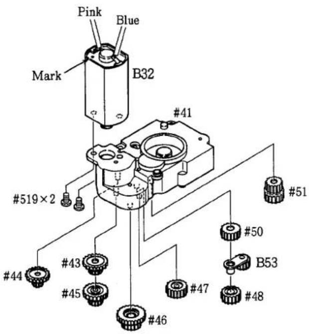
- Apply slightly grease G7100 to each gear and gear shaft.
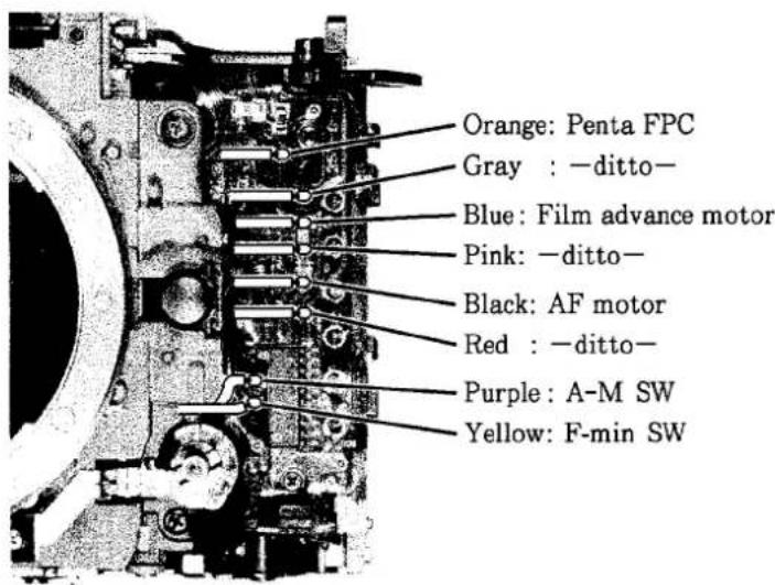
- Mounting order of the gears #43 → #44 → #51 → #50 → #45 → #46 → #47 → B53 → #48
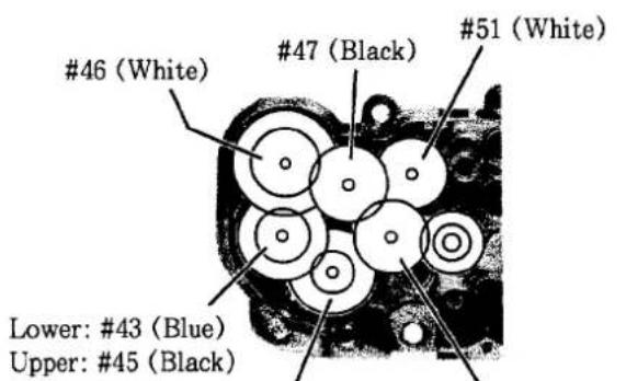
44 (Red)
Lower: #50 (White)
Middle: B53 (Black)
Upper: #48 (White)
2. Film advance lower base plate group
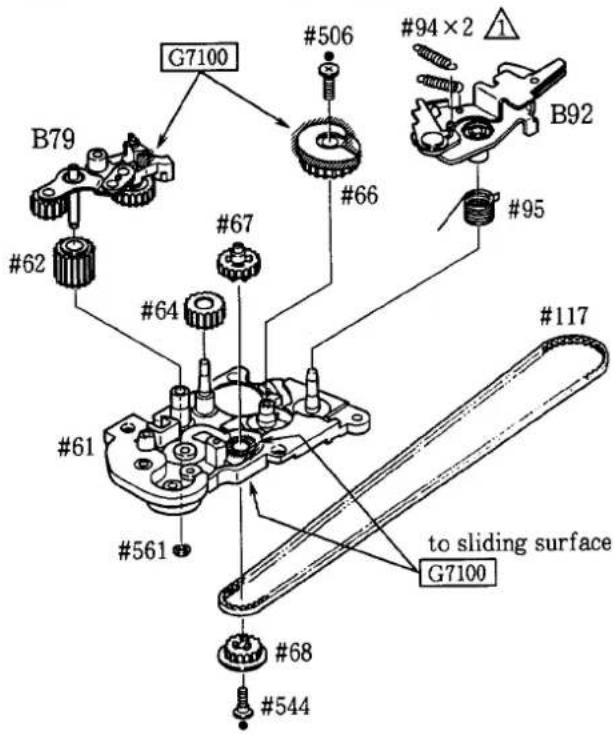
- Apply slightly grease G7100 to each gear and gear shaft. - After assembling, rotate the gear of B79 to set the film advance lower base plate group to charging-completion state.
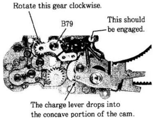
Charging-completion state
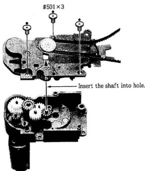
3. Mount lower base plate group on upper base plate group
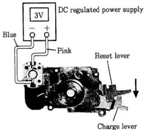
Inspection:
①Move the reset lever in the direction of arrow.
②As shown in the figure above, supply 3V to the film advance motor. Make sure that gear idles after moving charge lever and after changing to charging-completion state.
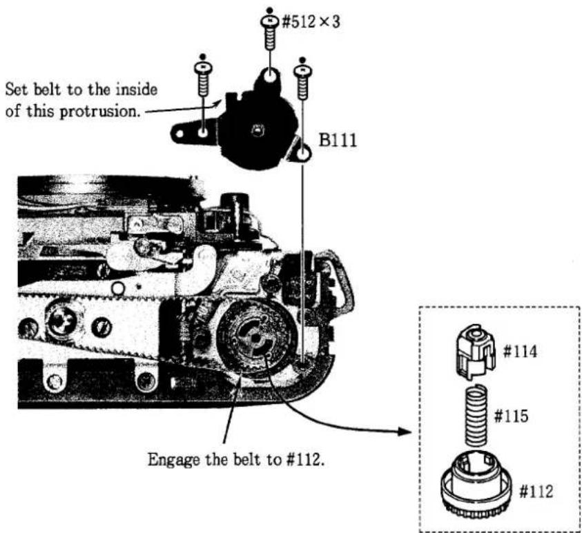
③ Turn the film advance motor in reverse direction to check if film rewind operation performs properly. Hold the motor to prevent the belt #117 from coming off.
④ After inspection, set to charging-completion state.
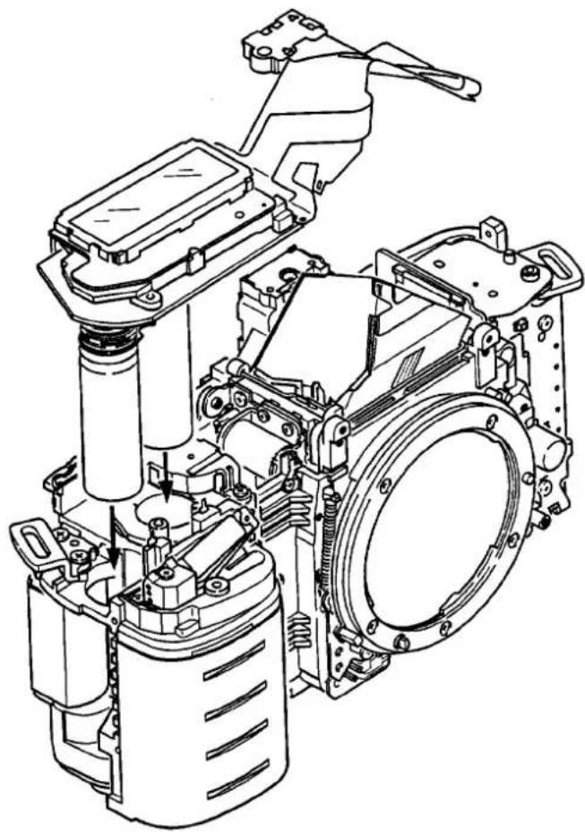
4. Mounting film advance mechanism group
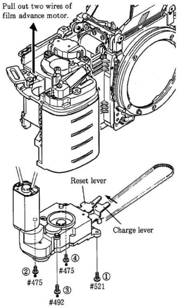
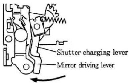
① Set the shutter charging lever and mirror driving lever of I base plate to shutter side.
② Mount the film advance mechanism group on the body. Pull out two wires of film advance motor through the hole as shown in the figure on the left.
③ Fasten screws in the order from ① to ④.
Note: If the second fastening screw #457 cannot be inserted due to the obstruction of other gear, move the charge lever on the film advance mechanism group in the direction of arrow to set the reset lever to the location shown in the figure on the left.
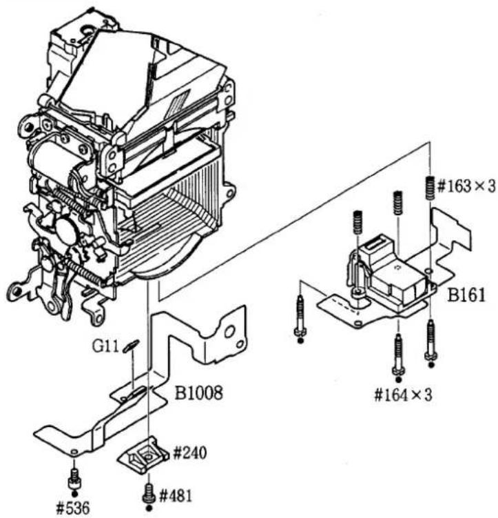
TRIPOD BASE PLATE B131
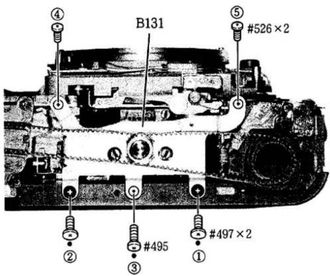
- Fasten screws in the order from ① to ⑤.
FILM REWIND FORK GROUP
SOLDERING BRIDGES, ARRANGE WIRES
PENTA FPC GROUP
- Assembling penta FPC group

2. Mounting penta FPC group
natural_image
Technical line drawing of a mechanical assembly with no visible text or symbols3. Connecting connectors
4. Soldering wires, Soldering bridges
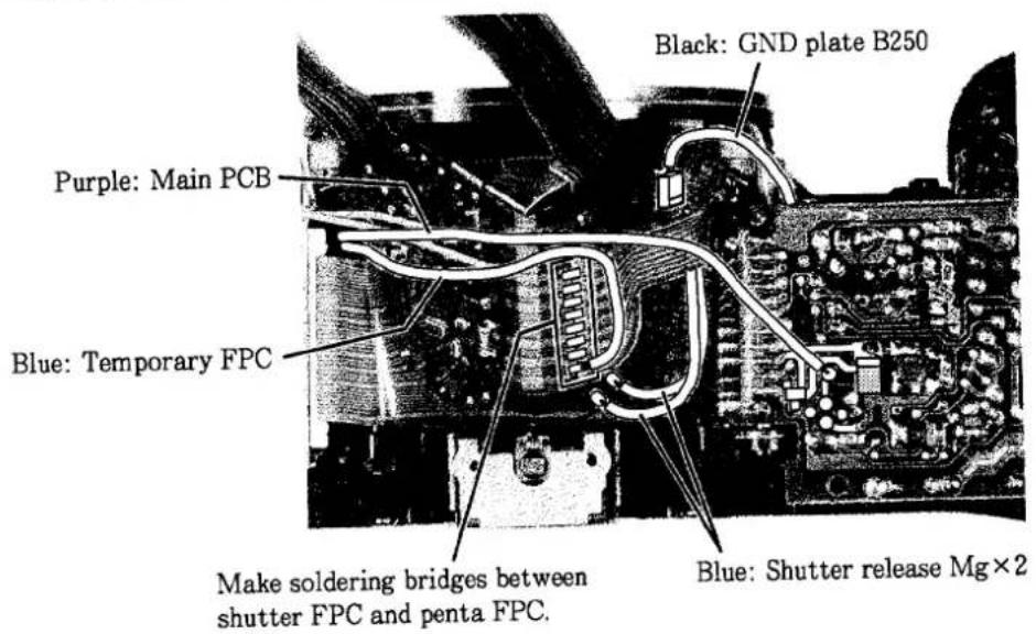
5. Attaching screws
6. Soldering wires, Soldering bridges
ARRANGE WIRES
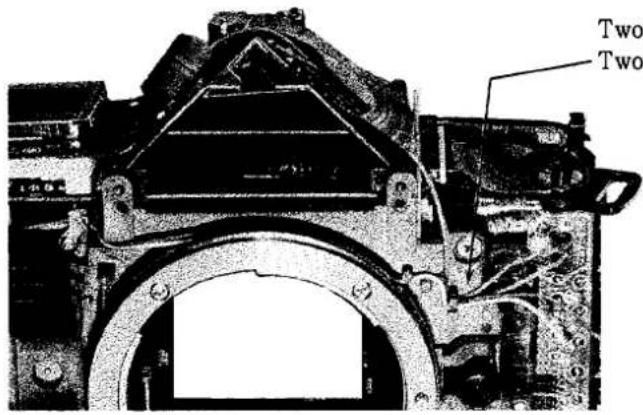
Two wires from film advance motor. Two wires from penta FPC.
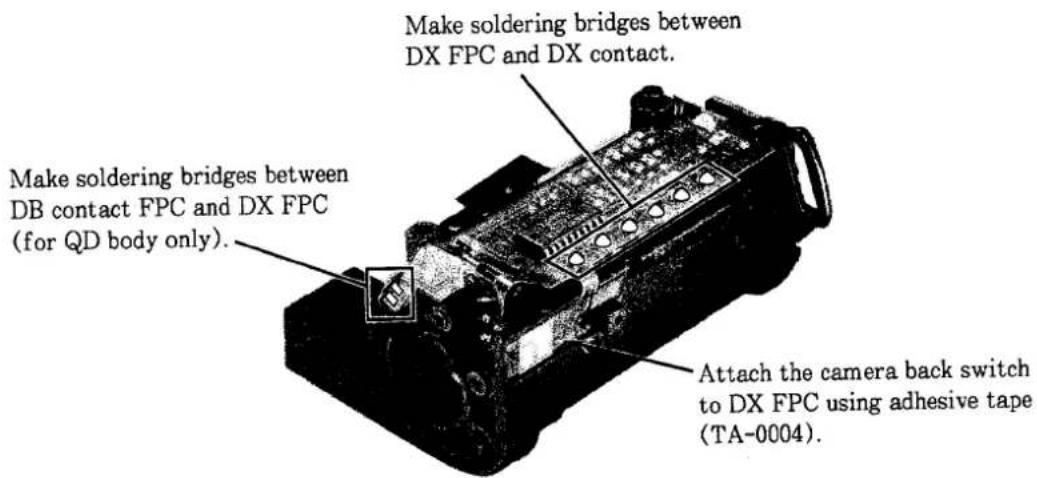
SOLDERING WIRES ON THE DX FPC
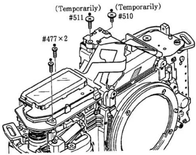
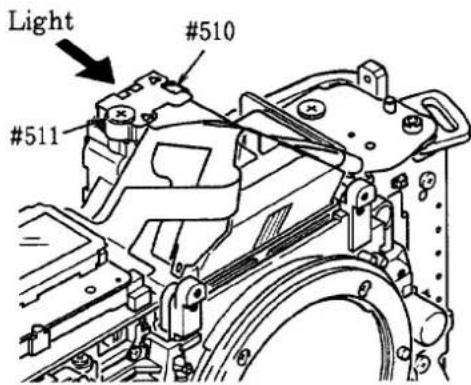
ADJUSTMENT OF AE SPD POSITION
natural_image
Abstract geometric diagram with a central circular shape and four surrounding rectangular regions (no text or symbols)① Unfasten screws #510 and #511.
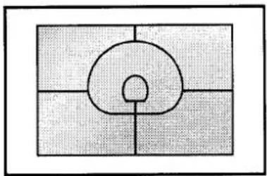
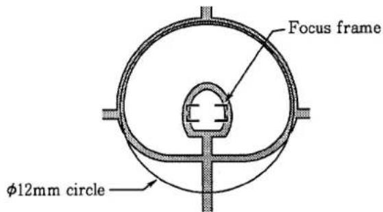
② Irradiate a strong light on the AE SPD so that the AE SPD patterns are reflected on the main mirror.
(Refer to the figure below on the left.)
③ As shown the figure below, align the center of the AE SPD with both the wide focus frame and the 12mm circle. The AE SPD should be parallel to the main mirror.
FRONT COVER, CAMERA BACK LOCK RELEASE, HAND GRIP REAR COVER
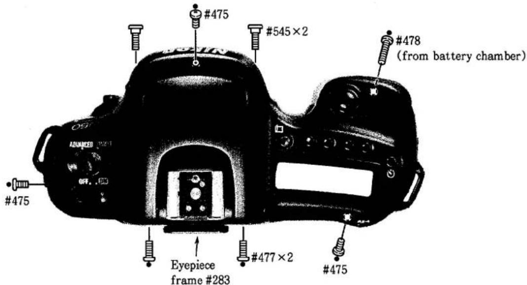
TOP COVER
- Mounting of each part (I)
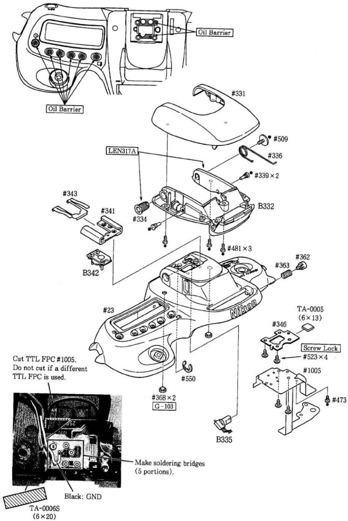
- Mounting of each part (II)
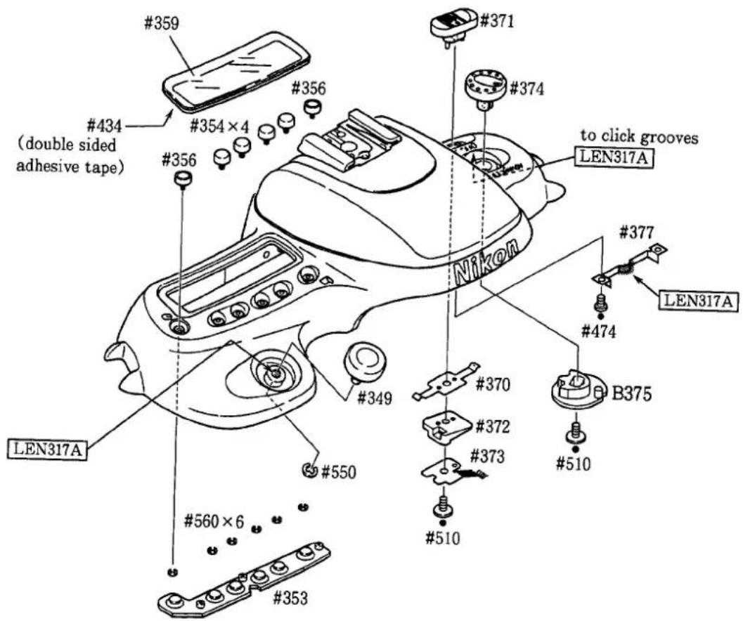
- Soldering wires, Press-contact
- Mounting top cover
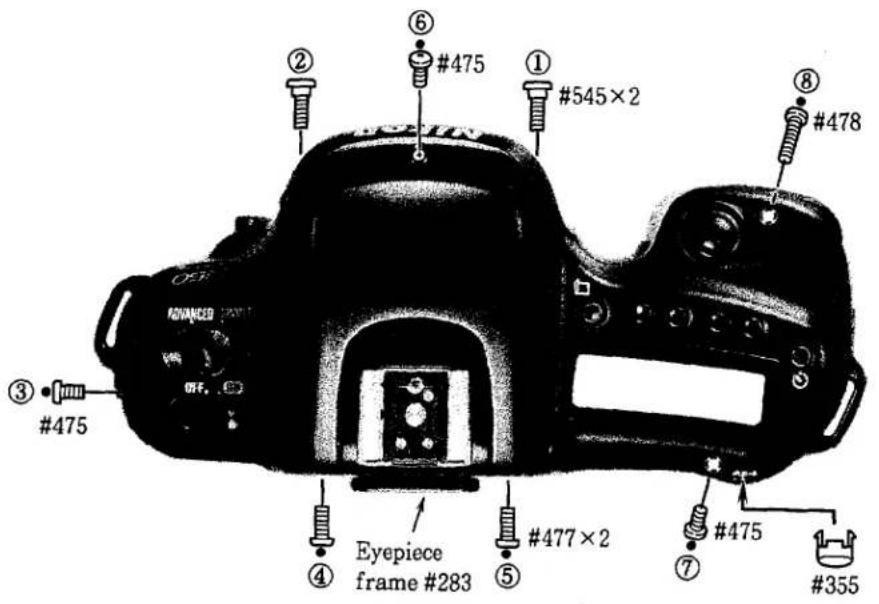
- Fasten screws in the order from ① to ⑧.
INSPECTION & ADJUSTMENT OF BODY BACK
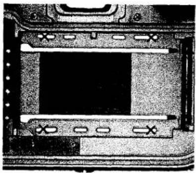
natural_image
Interior view of a computer case with drive bays and buttons (no visible text or symbols)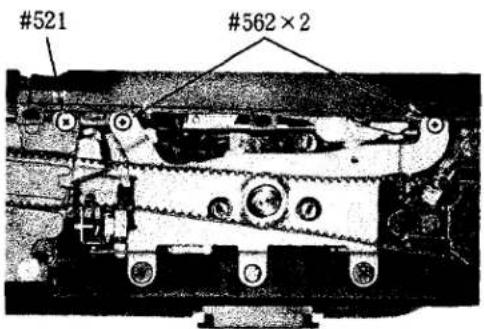
● Measure the distance between the lens mount surface and the outer film guide rail.
Mark ×: Measured positions
Standard value: 46.67±0.02mm
Degree of parallel: within 0.02mm
- If the measured value is out of the standard value, unfasten three screws as shown in the picture on the left to move the front body back and forth.
Or adjust the distance by inserting the washers under the lens mount.
INSPECTION & ADJUSTMENT OF AE, AF, TTL, BATTERY CHECK VOLTAGE
● Make each inspection and adjustment as indicated on the computer display.
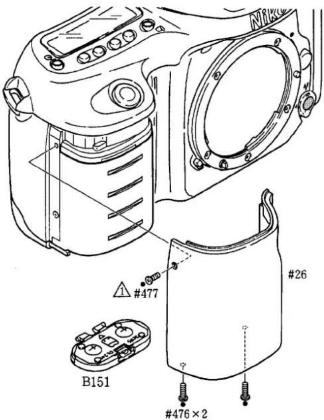
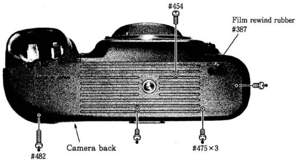
BOTTOM COVER, CAMERA BACK
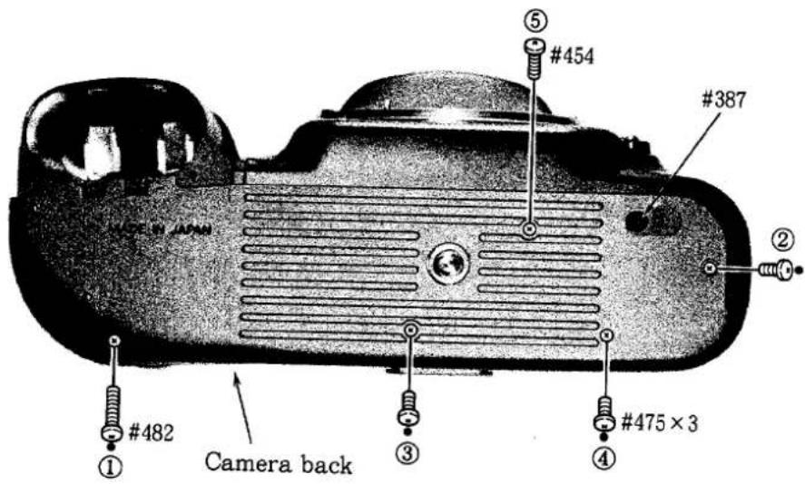
①Mount the camera back.
② Mount the bottom cover. Do not forget to attach film rewind rubber #387.
③ Fasten screws in the order from ① to ⑤.
HAND GRIP FRONT COVER, BATTERY CHAMBER COVER
CHECK & CLEAN
- Refer to the standard value of inspection and checking & adjustment programs.
電気編
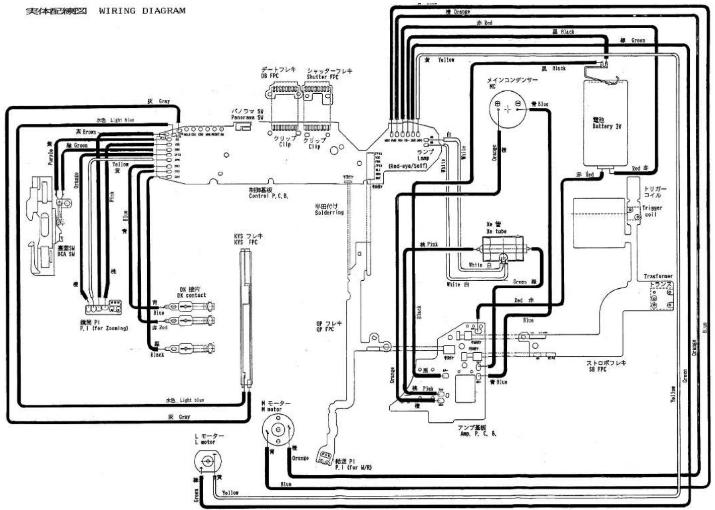
实体配線図 E1
回路図 E3
1001 メインPCB E5
1002 ペンタPCB E10
1003 CCD PCB E12
1004 前ボディPCB E13
1006 内LCD PCB E14
1007 卷き戻しPCB E15
1008 TTL PCB E16
1003 CCD PCB E12
1004 前ボディPCB E13
1006 内LCD PCB E14
1007 卷き戻しPCB E15
1008 TTL PCB E16
1006 内LCD PCB E14
1007 卷き戻しPCB E15
1008 TTL PCB E16
1008 TTL PCB E16
電気回路説明 E17
スイッチ名称表 E20
CPUピン配置表 E21
チェックランド表 E25
EEPROMデータ表 E28
Electric Circuit
WIRING DIAGRAM E 1
CIRCUIT DIAGRAM E 3
1001 MAIN PCB E 5
1002 PENTAPRISM PCB E 1 0
1003 CCD PCB E 1 2
1004 FRONT BOODY PCB E 1 3
1006 INTERNAL CCD PCB E 1 4
1007 FILM REWIND PCB E 1 5
1008 TTL PCB E 1 6
1003 CCD PCB E 1 2
1004 FRONT BOODY PCB E 1 3
1006 INTERNAL CCD PCB E 1 4
1007 FILM REWIND PCB E 1 5
1008 TTL PCB E 1 6
1006 INTERNAL CCD PCB E 1 4
1007 FILM REWIND PCB E 1 5
1008 TTL PCB E 1 6
1008 TTL PCB E 1 6
OUTLINE E 17
SWITCH TABLE E20
PIN NAME TABLE E 2 1
CHECK LAND NAME TABLE E 25
EEPROM DATA E 28
flowchart
graph TD
    A["实体配線图"] --> B["水色 Light blue"]
    A --> C["灰 Gray"]
    A --> D["黑 Brown"]
    A --> E["绿 Green"]
    A --> F["橙色"]
    A --> G["Orange"]
    A --> H["Yellow"]
    A --> I["Pink"]
    A --> J["Blue"]
    A --> K["青"]
    A --> L["桃"]
    A --> M["橙色 SW"]
    A --> N["BCA SW"]
    A --> O["高亮 SW"]
    A --> P["洗碗 P1 P.1 (for Zooming)"]
    A --> Q["洗碗 P1 P.1 (for Zooming)"]
    A --> R["洗碗 P1 P.1 (for Zooming)"]
    A --> S["洗碗 P1 P.1 (for Zooming)"]
    A --> T["洗碗 P1 P.1 (for Zooming)"]
    A --> U["洗碗 P1 P.1 (for Zooming)"]
    A --> V["洗碗 P1 P.1 (for Zooming)"]
    A --> W["洗碗 P1 P.1 (for Zooming)"]
    A --> X["洗碗 P1 P.1 (for Zooming)"]
    A --> Y["洗碗 P1 P.1 (for Zooming)"]
    A --> Z["洗碗 P1 P.1 (for Zooming)"]
    A --> AA["洗碗 P1 P.1 (for Zooming)"]
    A --> AB["洗碗 P1 P.1 (for Zooming)"]
    A --> AC["洗碗 P1 P.1 (for Zooming)"]
    A --> AD["洗碗 P1 P.1 (for Zooming)"]
    A --> AE["洗碗 P1 P.1 (for Zooming)"]
    A --> AF["洗碗 P1 P.1 (for Zooming)"]
    A --> AG["洗碗 P1 P.1 (for Zooming)"]
    A --> AH["洗碗 P1 P.1 (for Zooming)"]
    A --> AI["洗碗 P1 P.1 (for Zooming)"]
    A --> AJ["洗碗 P1 P.1 (for Zooming)"]
    A --> AK["洗碗 P1 P.1 (for Zooming)"]
    A --> AL["洗碗 P1 P.1 (for Zooming)"]
    A --> AM["洗碗 P1 P.1 (for Zooming)"]
    A --> AN["洗碗 P1 P.1 (for Zooming)"]
    A --> AO["洗碗 P1 P.1 (for Zooming)"]
    A --> AP["洗碗 P1 P.1 (for Zooming)"]
    A --> AQ["洗碗 P1 P.1 (for Zooming)"]
    A --> AR["洗碗 P1 P.1 (for Zooming)"]
    A --> AS["洗碗 P1 P.1 (for Zooming)"]
    A --> AT["洗碗 P1 P.1 (for Zooming)"]
    A --> AU["洗碗 P1 P.1 (for Zooming)"]
    A --> AV["洗碗 P1 P.1 (for Zooming)"]
    A --> AW["洗碗 P1 P.1 (for Zooming)"]
    A --> AX["洗碗 P1 P.1 (for Zooming)"]
    A --> AY["洗碗 P1 P.1 (for Zooming)"]
    A --> AZ["洗碗 P1 P.1 (for Zooming)"]
    A --> BA["洗碗 P1 P.1 (for Zooming)"]
    A --> BB["洗碗 P1 P.1 (for Zooming)"]
    A --> BC["洗碗 P1 P.1 (for Zooming)"]
    A --> BD["洗碗 P1 P.1 (for Zooming)"]
    A --> BE["洗碗 P1 P.1 (for Zooming)"]
    A --> BF["洗碗 P1 P.1 (for Zooming)"]
    A --> BG["洗碗 P1 P.1 (for Zooming)"]
    A --> BH["洗碗 P1 P.1 (for Zooming)"]
    A --> BI["洗碗 P1 P.1 (for Zooming)"]
    A --> BJ["洗碗 P1 P.1 (for Zooming)"]
    A --> BK["洗碗 P1 P.1 (for Zooming)"]
    A --> BL["洗碗 P1 P.1 (for Zooming)"]
    A --> BM["洗碗 P1 P.1 (for Zooming)"]
    A --> BN["洗碗 P1 P.1 (for Zooming)"]
    A --> BO["洗碗 P1 P.1 (for Zooming)"]
    A --> BP["洗碗 P1 P.1 (for Zooming)"]
    A --> BQ["洗碗 P1 P.1 (for Zooming)"]
    A --> BR["洗碗 P1 P.1 (for Zooming)"]
    A --> BS["洗碗 P1 P.1 (for Zooming)"]
    A --> BT["洗碗 P1 P.1 (for Zooming)"]
    A --> BU["洗碗 P1 P.1 (for Zooming)"]
    A --> BV["洗碗 P1 P.1 (for Zooming)"]
    A --> BW["洗碗 P1 P.1 (for Zooming)"]
    A --> BX["洗碗 P1 P.1 (for Zooming)"]
    A --> BY["洗碗 P1 P.1 (for Zooming)"]
    A --> BZ["洗碗 P1 P.1 (for Zooming)"]
    A --> CA["洗碗 P1 P.1 (for Zooming)"]
    A --> CB["洗碗 P1 P.1 (for Zooming)"]
    A --> CC["洗碗 P1 P.1 (for Zooming)"]
    A --> CD["洗碗 P1 P.1 (for Zooming)"]
    A --> CE["洗碗 P1 P.1 (for Zooming)"]
    A --> CF["洗碗 P1 P.1 (for Zooming)"]
    A --> CG["洗碗 P1 P.1 (for Zooming)"]
    A --> CH["洗碗 P1 P.1 (for Zooming)"]
    A --> CI["洗碗 P1 P.1 (for Zooming)"]
    A --> CJ["洗碗 P1 P.1 (for Zooming)"]
    A --> CK["洗碗 P1 P.1 (for Zooming)"]
    A --> CR["洗碗 P1 P.1 (for Zooming)"]
    A --> CS["洗碗 P1 P.1 (for Zooming)"]
    A --> CT["洗碗 P1 P.1 (for Zooming)"]
    A --> CU["洗碗 P1 P.1 (for Zooming)"]
    A --> CV["洗碗 P1 P.1 (for Zooming)"]
    A --> CW["洗碗 P1 P.1 (for Zooming)"]
    A --> CX["洗碗 P1 P.1 (for Zooming)"]
    A --> CY["洗碗 P1 P.1 (for Zooming)"]
    A --> CZ[洗碗 P1P 5 5 5 5 5 5 5 5 5 5 5 5 5 5 5 5 5 5 5 5 5 5 5 5 5 5 5 5 5 5 5 5 5 5 5 5 5 5 5 5 5 5 5 5 5 5 5 5 5 5 0 0 0
    B --> C
    C --> D
    D --> E
    D --> F
    D --> G
    D --> H
    D --> I
    D --> J
    D --> K
    D --> L
    D --> M
    D --> N
    D --> O
    D --> PC
    D --> Q
    D --> R
    D --> S
    D --> T
    D --> U
    D --> V
    D --> W
    D --> X
    D --> Y
    D --> Z
    D --> AA
    D --> AB
    D --> AC
    D --> AD
    D --> AE
    D --> AF
    D --> AG
    D --> AH
    D --> AI
    D --> AJ
    D --> AK
    D --> AL
    D --> AM
    D --> AN
    D --> AO
    D --> AP
    D --> AQ
    D --> AR
    D --> AS
    D --> AT
    D --> AU
    D --> AV
    D --> AW
    D --> AX
    D --> AY
    D --> AZ
    D --> BA
    D --> BB
    D --> BC
    D --> BD
    D --> BE
    D --> BF
    D --> BG
    D --> BH
    D --> BI
    D --> BJ
    D --> BK
    D --> BL
    D --> BM
    D --> BN
    D --> BO
    D --> BP
    D --> BQ
    D --> BR
    D --> BS
    D --> BT
    D --> BU
    D --> BV
    D --> BW
    D --> BX
    D --> BY
    D --> BZ
    D --> CA
    D --> CB
    D --> CC
    D --> CD
    D --> CE
    D --> CF
</details>

<details>
<summary>text_image</summary>
实体配線図 WIRING DIAGRAM
FAA29051-R.3340.A
量達初期品
ORIGINAL
AELFPC
Pre-release SW
白 半PELSW
White
Black
Release SW
Red
+
-
DC-DC コンバータ
DC-DC converter
電池 Battery
リチウム電池 Lithium battery
内蔵ストロボ
Built-in flash
内蔵ストロボ
Built-in flash
黑白
Blue
Black
Black
Blue
Black
Blue
Blue
Blue
Blue
Blue
Blue
Blue
Blue
Blue
Blue
Blue
Blue
Blue
Blue
Blue
Blue
Blue
Blue
Blue
Blue
Blue
Blue
Blue
Blue
Blue
Blue
Blue
Blue
Blue
Blue
Blue
Blue
Blue
Blue
Blue
Blue
Blue
Blue
Blue
Blue
Blue
Blue
Blue
Blue
Blue
Blue
Blue
Blue
Blue
Blue
Black
外観液晶モジュール External LCD module
Black
青 Blue
青 Blue
Black
Blue
Release Mg
Black
Blue
Blue
Release Mg
Black
灰
シャッターユニット Shutter unit
灰色
橙色 PCB Main PCB Orange 植
青 Blue
暫定FPC Black 里 White LPS C.B. Sprocket P.C.R.
Orange 植 White LPS C.B. Sprocket P.C.R.
Orange 植 White LPS C.B. Sprocket P.C.R.
Orange 植 White LPS C.B. Sprocket P.C.R.
Orange 植 White LPS C.B. Sprocket P.C.R.
Orange 植 White LPS C.B. Sprocket P.C.R.
Orange 植 White LPS C.B. Sprocket P.C.R.
Orange 精 White LPS C.B. Sprocket P.C.R.
Orange 精 White LPS C.B. Sprocket P.C.R.
Orange 精 White LPS C.B. Sprocket P.C.R.
Orange 精 White LPS C.B. Sprocket P.C.R.
Orange 精 White LPS C.B. Sprocket P.C.R.
Orange 精 White LPS C.B. Sprocket P.C.R.
Orange 植 White LPS C.B. Sprocket P.C.R.
Orange 植 White LPS C.B. Sprocket P.C.R.
Orange 植 White LPS C.B. Sprocket P.C.R.
Orange 植 White LPS C.B. Sprocket P.C.R.
Orange 植 White LPS C.B. Sprocket P.C.R.
Orange 颜色 PCB Main PCB Orange 植 White LPS C.B. Sprocket P.C.R.
Orange 颜色 PCB Main PCB Orange 植 White LPS C.B. Sprocket P.C.R.
Orange 颜色 PCB Main PCB Orange 植 White LPS C.B. Sprocket P.C.R.
Orange 颜色 PCB Main PCB Orange 植 White LPS C.B. Sprocket P.C.R.
Orange 颜色PCB Main PCB Orange 植 White LPS C.B. Sprocket P.C.R.
Orange 颜色PCB Main PCB Orange 植 White LPS C.B. Sprocket P.C.R.
Orange 颜色PCB Main PCB Orange 植 White LPS C.B. Sprocket P.C.R.
Orange 颜色PCB Main PCB Orange 植 White LPS C.B. Sprocket P.C.R.
Orange 精 White LPS C.B. Sprocket P.C.R.
Orange 颜色PCB Main PCB Orange 植 White LPS C.B. Sprocket P.C.R.
Orange 颜色PCB Main PCB Orange 植 White LPS C.B. Sprocket P.C.R.
Orange 颜色PCB Main PCB Orange 植 White LPS C.B. Sprocket P.C.R.
Orange 颜色PCB Main PCS Main PCB Orange 植 White LPS C.B. Sprocket P.C.R.
Orange 颜色PCB Main PCB Orange 植 White LPS C.B. Sprocket P.C.R.
Orange 颜色PCB Main PCB Orange 植 White LPS C.B. Sprocket P.C.R.
Orange 颜色PCB Main PCB Orange 植 White LPS C.B. Sprocket P.C.R.
Orange 风色PCB Main PCB Orange 植 White LPS C.B. Sprocket P.C.R.
Orange 风色PCB Main PCB Orange 植 White LPS C.B. Sprocket P.C.R.
Orange 风色PCB Main PCB Orange 植 White LPS C.B. Sprocket P.C.R.
Orange 风色PCB Main PCB Orange 植 White LPS C.B. Sprocket P.C.R .
Orange 风色PCB Main PCB Orange 植 White LPS C.B. Sprocket P.C.R .
Orange 风色PCB Main PCB Orange 植 White LPS C.B. Sprocket P.C.R .
Orange 风色PCB Main PCB Orange 植 White LPS C.B. Sprocket P.C.R .
Orange 风色PCB Main PCB Orange 植 White LPS C.B. Sproplet P.C.R .
Orange 风色PCB Main PCB Orange 植 White LPS C.B. Sproplet P.C.R .
Orange 风色PCB Main PCB Orange 植 White LPS C.B. Sproplet P.C.R .
Orange 风色PCB Main PCB Orange 植 White LPS C.B. Sproplet P.C.R .
Orange 风色PCB Main PCB Orange 植 White LPS C.D.PFC . . .
Yellow - 良状LED LED Illuminator LED
Yellow - 良状LED LED Illuminator LED
Yellow - 良状LED LED Illuminator LED
Yellow - 良状LED LED Illuminator LED
Yellow - 良状LED LED Illuminator LED
Yellow - 良状LED LED Illuminator LED
Yellow - 良状LED LED Illuminator LED
Yellow - 良状LED LED Illuminator LED
Yellow - 良状LED LED Illuminator LED
Yellow - 花状LED LED Illuminator LED
Yellow - 花状LED LED Illuminator LED
Yellow - 花状LED LED Illuminator LED
Yellow - 花状LED LED Illuminator LED
Yellow - 花状LED LED Illuminator LED
Yellow - 花状LED LED Illuminator LED
Yellow - 花状LED LED Illuminator LED
Yellow - 花状LED LED Illuminator LED
Yellow - 花状LED LED Immulator LED
Yellow - 花状LED LED Immulator LED
Yellow - 花状LED LED Immulator LED
Yellow - 花状LED LED Immulator LED
Yellow - 花状LED LED Immulator LED
Yellow - 花状LED LED Immulator LED
Yellow - 花状LED LED Immulator LED
Yellow - 花状LED LED Immulator LED
Yellow - 花状LED LED Immulator LED
Yellow -
CCDFPC
DBFPC
</details>
- F 1 . D50 -

<details>
<summary>text_image</summary>
FAA29051-R.3340.A
AELFPC
Pre-release SW
White 半伏L.SW
Black
Release SW
Red
Re
電池
Battery
外観液晶モジュール
External LCD module
DC-DC コンバータ
DC-DC converter
黑白
桃
Pink
リチウム電池 Lithium battery
内蔵ストロボ
Built-in flash
黒 Black
ペンタPPC
Pentagrise PPC
Black
Blue
Blue
Release Mg
レリーズMg
スプロP.C.B.
Sprocket P.C.B.
Orange 橙
紫 Purple
AFSW
紅 Purple
藍 Blue
暫定FPC
Orange 橙
室内 LCD PPC
フィインダー内 LCD FPC
イルミ LED
Illuminator LED
Orange 橙
セルプ LED
Self-timer LED
ネットシャーFPC
Hot shoe PPC
給湯モーター
Film advance actor
AFモーター
AP motor
検 Pink
Black
黄 Red
黄色
FminSW
ボディアース
Body GMO
AFPIFPC
TTLFPC
CCDFPC
ファインダー内液晶
Finder LCD
DBFPC
图信丁一 1
REVISED-1
</details>

<details>
<summary>text_image</summary>
FAA29051-R. 3340.A
AELFPC
Pre-release SW
White 半接LSW
Black
Release SW
Red
電池 Battery
外部液晶モジュール
External LCD module
DC-DC コンバータ
DC-DC converter
リチウム電池 Lithium battery
内嵌ストロボ
Built-in flash
ペンタPPC
Pentaprison PPC
黑白
Blue
Release Mg
レリーズMg
黒
灰
スプロP.C.B.
Sprocket P.C.B.
Orange 橙
シャッターユット
Shatter unit
巻き斑LPPC
Rewind PPC
橙色
HPPT
HPPT
HPPT
HPPT
HPPT
HPPT
HPPT
HPPT
HPPT
HPPT
HPPT
HPPT
HPPT
HPPT
HPPT
HPPT
HPPT
HPPT
HPPT
HPPT
HPPT
HPPT
HPPT
HPPT
HPPT
HPPT
HPPT
HPPT
HPPT
HPPT
HPPT
HPPT
HPPT
HPPT
</details>

<details>
<summary>flowchart</summary>
```mermaid
graph TD
A["LED module"] --> B["PCB"]
B --> C["Power module P.C.B."]
C --> D["Sprocket P.C.B."]
D --> E["Shutter unit"]
E --> F["Internal LCD PPC"]
F --> G["Clocked PFC"]
G --> H["Reset side PPC"]
H --> I["Motor 1ch CAP"]
I --> J["Motor 2ch CFilm advance"]
J --> K["DBFPC"]
K --> L["Hot show PPC"]
L --> M["CCDFPC"]
M --> N["TTLFPC"]
N --> O["Motor 1ch (REF)"]
O --> P["Motor 2ch (REF)"]
P --> Q["Reset side PPC"]
Q --> R["Reset side PPC"]
R --> S["Motor 1ch (REF)"]
S --> T["Motor 2ch (REF)"]
T --> U["Reset side PPC"]
U --> V["Reset side PPC"]
V --> W["Motor 1ch (REF)"]
W --> X["Motor 2ch (REF)"]
X --> Y["Reset side PPC"]
Y --> Z["Reset side PPC"]
Z --> AA["Motor 1ch (REF)"]
AA --> AB["Motor 2ch (REF)"]
AB --> AC["Reset side PPC"]
AC --> AD["Reset side PPC"]
AD --> AE["Motor 1ch (REF)"]
AE --> AF["Motor 2ch (REF)"]
AF --> AG["Reset side PPC"]
AG --> AH["Reset side PPC"]
AH --> AI["Motor 1ch (REF)"]
AI --> AJ["Motor 2ch (REF)"]
AJ --> AK["Reset side PPC"]
AK --> AL["Reset side PPC"]
AL --> AM["Motor 1ch (REF)"]
AM --> AN["Motor 2ch (REF)"]
AN --> AO["Reset side PPC"]
AO --> AP["Reset side PPC"]
AP --> AQ["Motor 1ch (REF)"]
AQ --> AR["Motor 2ch (REF)"]
AR --> AS["Reset side PPC"]
AS --> AT["Reset side PPC"]
AT --> AU["Motor 1ch (REF)"]
AU --> AV["Motor 2ch (REF)"]
AV --> AW["Reset side PPC"]
AW --> AX["Reset side PPC"]
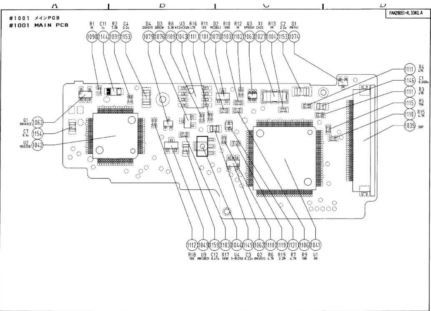
-E5·F50-
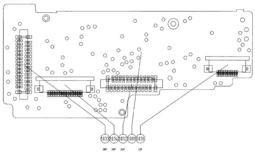
FAA29051-R.3340.A
)
)
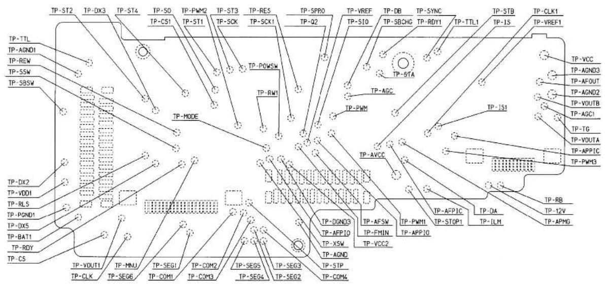
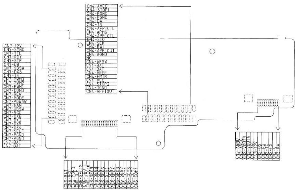
flowchart
graph TD
    A["CN7-2V"] --> B["CN4-AVCC"]
    A --> C["CN4-STOP1"]
    A --> D["CN4-PGND"]
    A --> E["CN4-DA"]
    A --> F["CN4-IS"]
    A --> G["CN4-AFPICTL"]
    A --> H["CN4-APMG"]
    A --> I["CN4-APPICTL"]
    A --> J["CN4-SIO"]
    A --> K["CN4-SCK"]
    A --> L["CN4-RNI"]
    A --> M["CN4-APPIOUT"]
    A --> N["CN4-AGND"]
    A --> O["NC"]
    A --> P["CN4-AFSW"]
    A --> Q["CN4-BAT"]
    A --> R["CN4-VREF"]
    A --> S["CN4-FMIN"]
    A --> T["CN4-VCC"]
    A --> U["CN4-STOP2"]
    A --> V["CN4-DGND"]
    A --> W["CN4-APIOUT"]
    X["CN7-SYNC"] --> Y["CN7-XX3"]
    Z["CN7-SP"] --> AA["CN7-PWM3"]
    AB["CN7-DB"] --> AC["CN7-PWM2"]
    AD["CN7-SRSW"] --> AE["CN7-PWM1"]
    AF["CN7-PS"] --> AG["CN7-PGND"]
    AH["CN7-PSW"] --> AI["CN7-HAN"]
    AJ["CN7-UBSW"] --> AK["CN7-VCC"]
    AL["CN7-OX6"] --> AM["CN7-OX2"]
    AN["CN7-OX5"] --> AO["CN7-OX4"]
    AP["CN7-SELF"] --> AQ["CN7-PGND"]
    AR["CN7-PGND"] --> AS["CN7-PGND"]
    AT["CN7-BAT"] --> AU["CN7-BAT"]

    B --> V
    V --> W
    W --> X
    X --> Y
    Y --> Z
    Z --> AA
    AA --> AB
    AB --> AC
    AC --> AD
    AD --> AE
    AE --> AF
    AF --> AG
    AG --> AH
    AH --> AI
    AI --> AJ

    subgraph Microcontroller
        direction LR
        V -->|Arrow to| W
        W -->|Arrow to| X
        X -->|Arrow to| Y
        Y -->|Arrow to| Z
        Z -->|Arrow to| AA
        AA -->|Arrow to| AB
        AB -->|Arrow to| AC
        AC -->|Arrow to| AD
        AD -->|Arrow to| AE
        AE -->|Arrow to| AF
        AF -->|Arrow to| AG
        AG -->|Arrow to| AH
        AH -->|Arrow to| AI
        AI -->|Arrow to| AJ

    end
FAA29051-R.3340.A
)
)
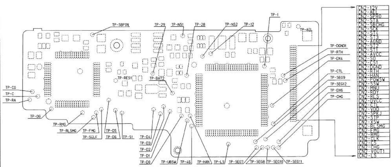
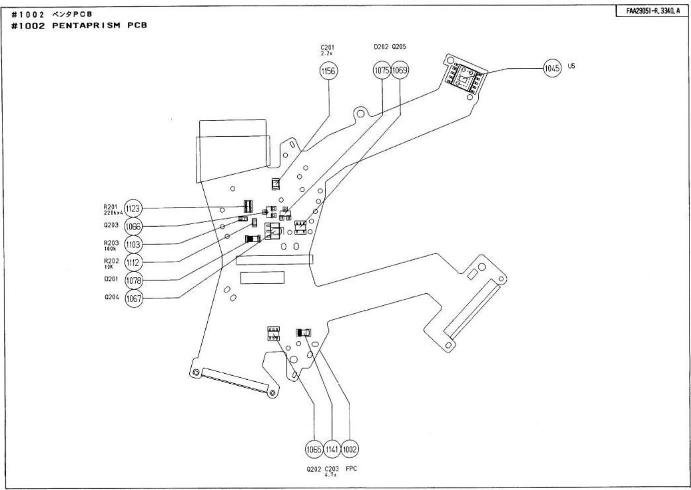
)
)
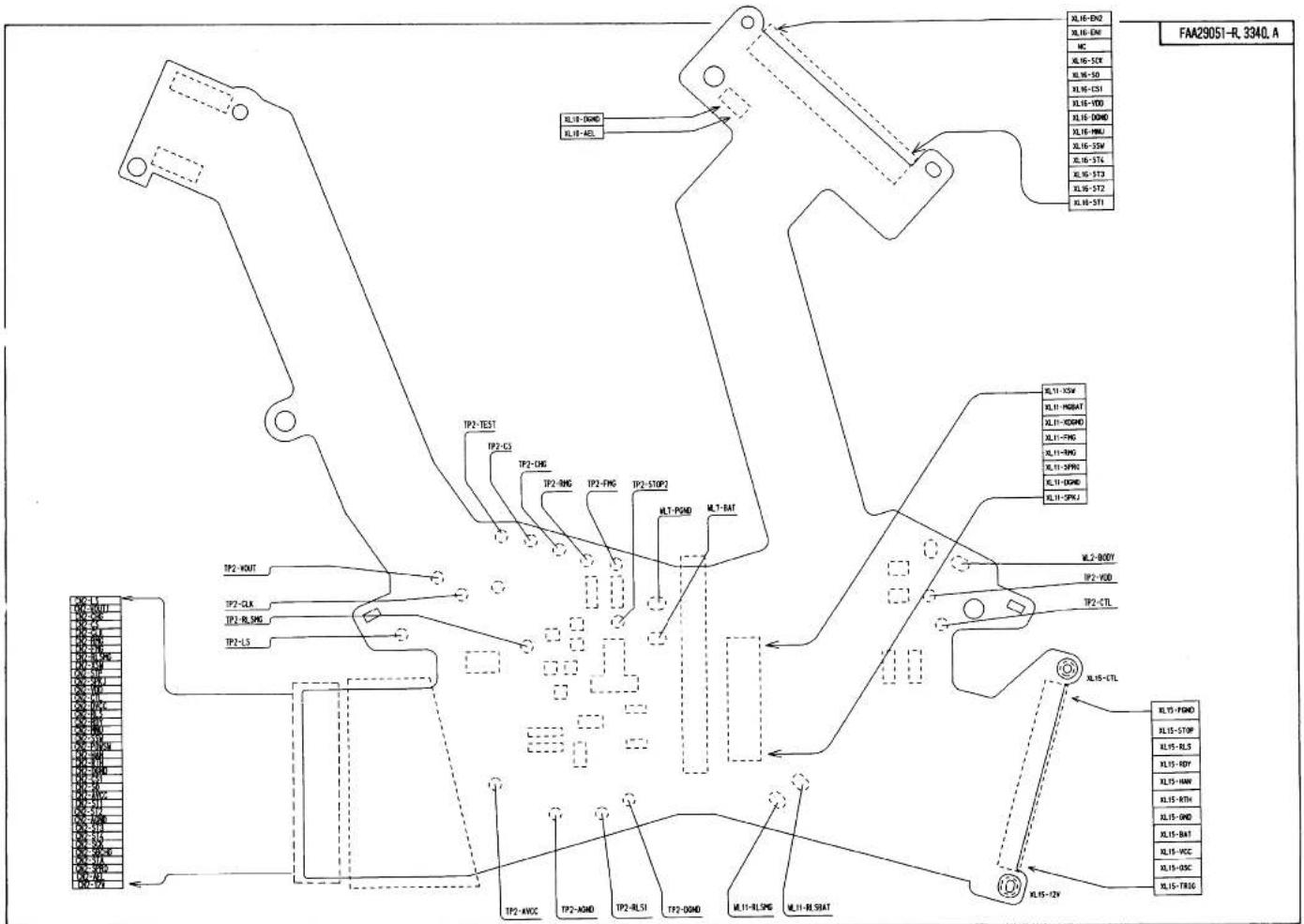
-E11·F50-
1003 CCD PCB
FAA29051-R.3340.A
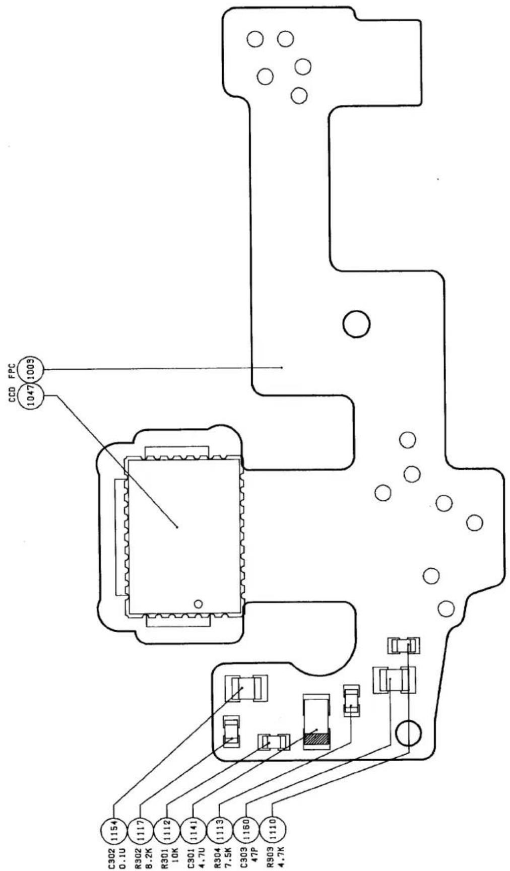
1004 前ボディPCB
FAA29051-R.3340.A
1004 FRONT BODY PCB
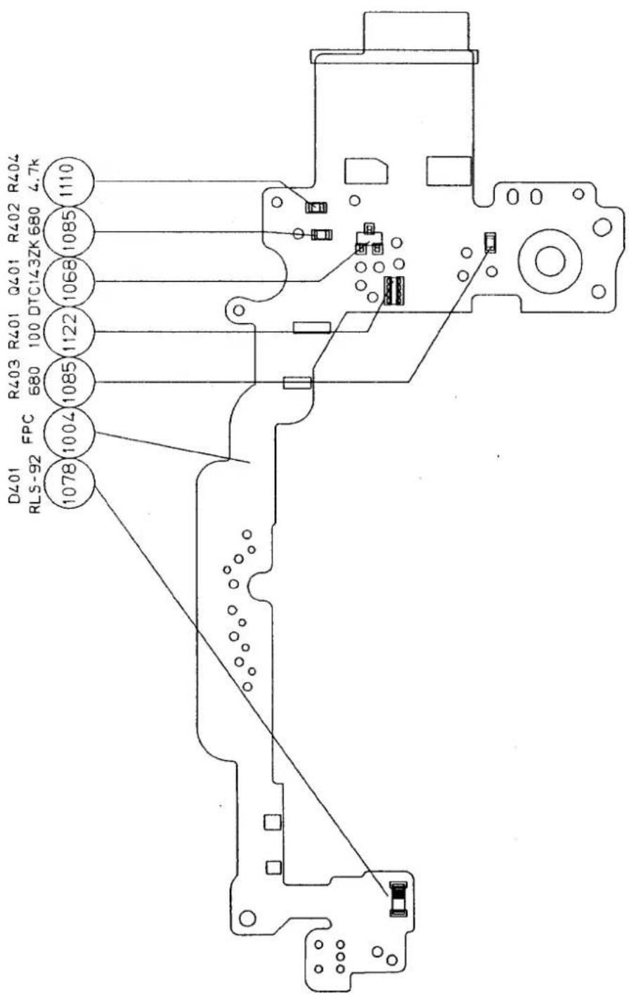
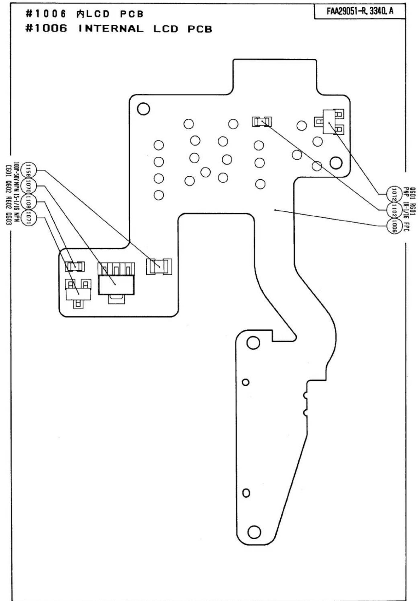
1007 巳き戻しPCB
FAA29051-R.3340.A
1007 FILM REWIND PCB
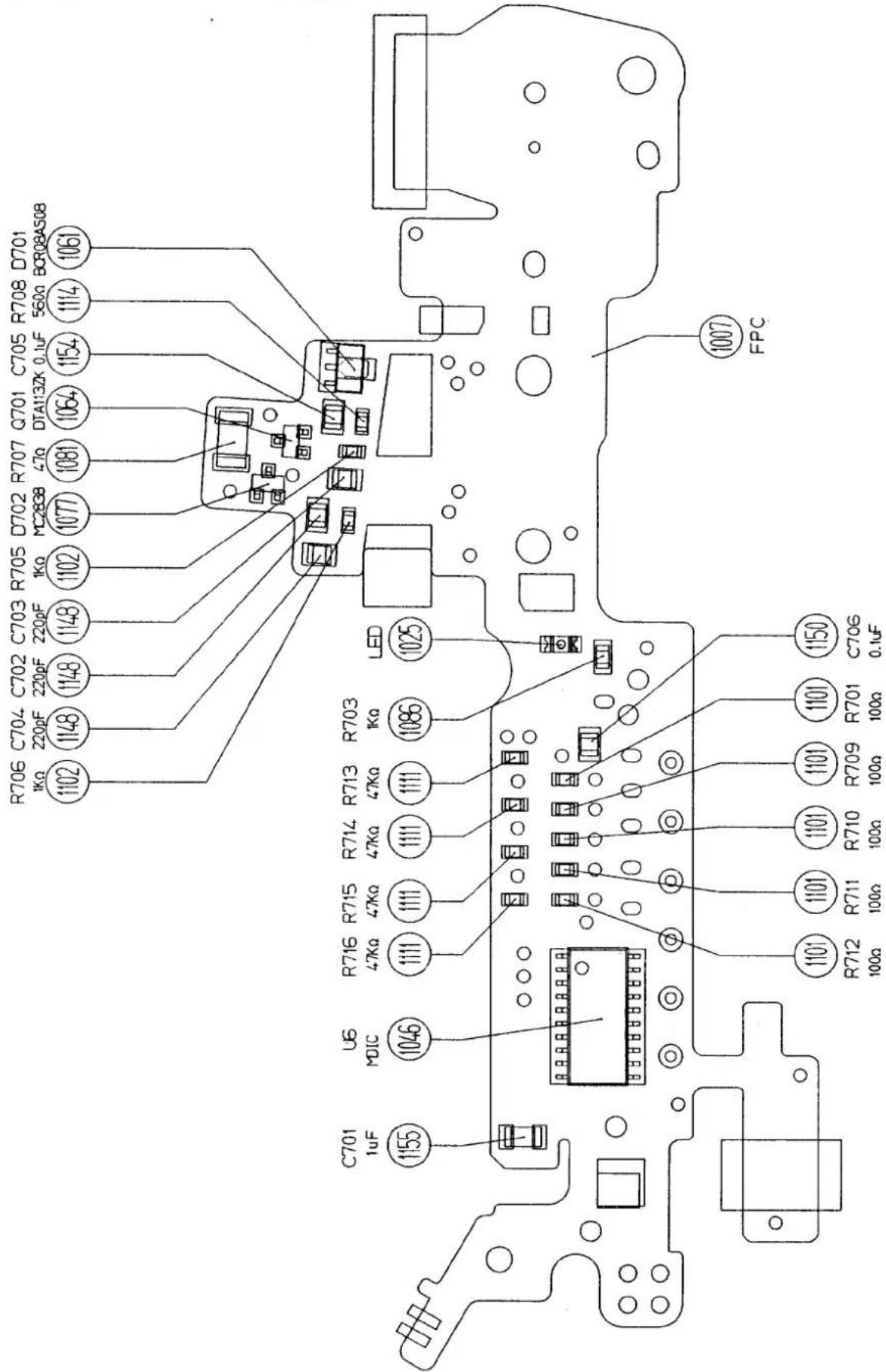
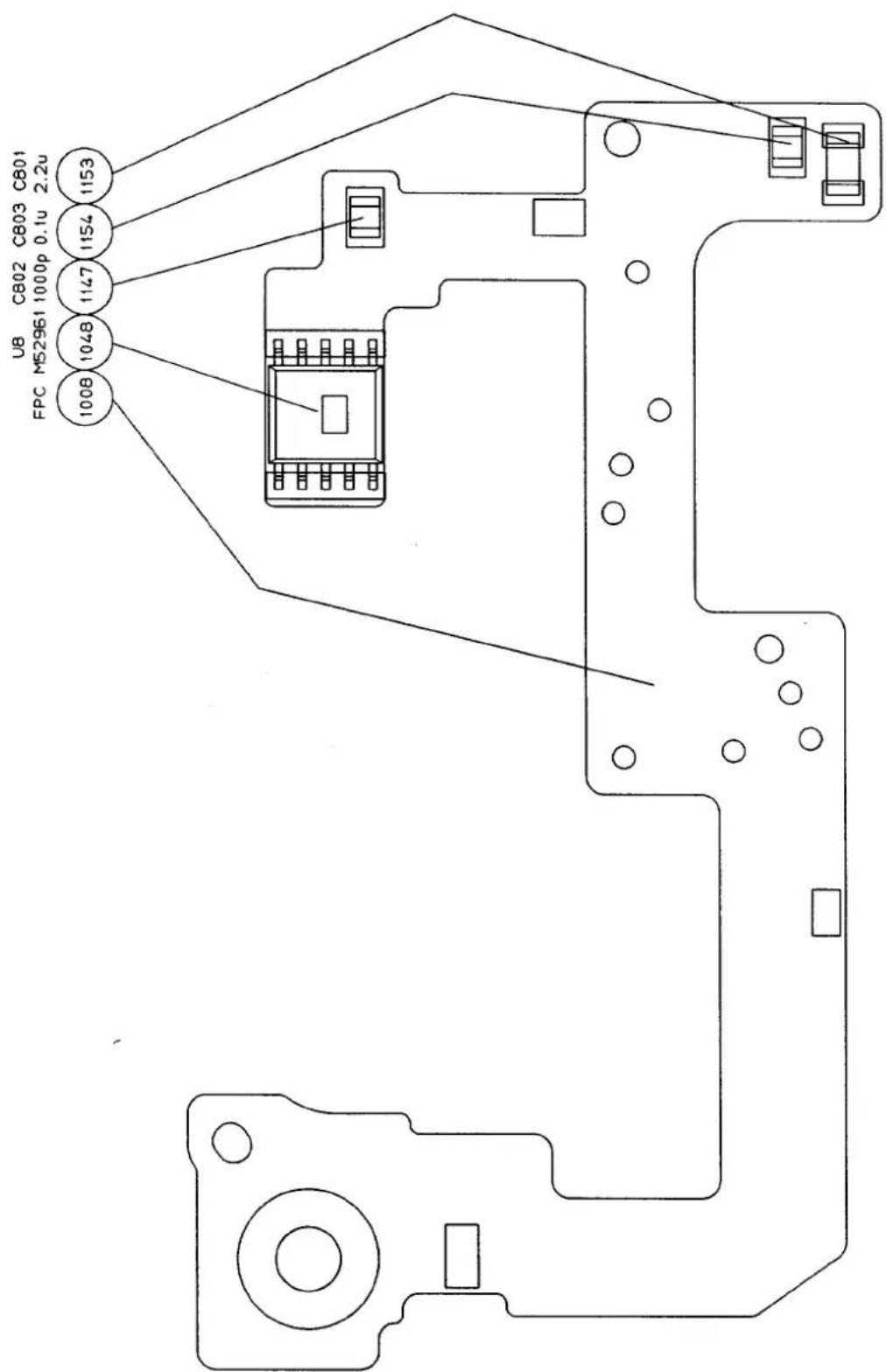
[2] 工具 TOOL
| 工具番号TOOL No. | 名称NAME | 区分CLASS |
| J 1 5 3 1 5 | カメラ通信工具CAMERA COMMUNICATION TOOL | A |
| J 1 8 2 3 8 A | 点検、調整用フロッピーディスク NEC PC-9801用 5インチINSPECTING & ADJUSTMENT FLOPPY DISK. FOR NEC 5' | A |
| J 1 8 2 3 8 B | 点検、調整用フロッピーディスク NEC PC-9801用 3.5インチINSPECTING & ADJUSTMENT FLOPPY DISK. FOR NEC 3.5' | |
| J 1 8 2 3 8 C | 点検、調整用フロッピーディスク IBM PC A/T用 5インチINSPECTING & ADJUSTMENT FLOPPY DISK. FOR IBM PC A/T 5' | |
| J 1 8 2 3 8 D | 点検、調整用フロッピーディスク IBM PC A/T用 3.5インチINSPECTING & ADJUSTMENT FLOPPY DISK. FOR IBM PC A/T 3.5' |
TOOL INSTRUCTION
SERVICE DEPT
J15315
- Name: Camera communication tool J15315
- Use: Communication of F50/N50.
- Before using this tool, modify communication box J15278.
● Outline of the modification.
《 Before modification 》
《 After modification 》
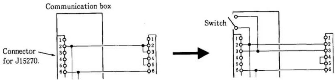
① Remove the cover of the connector (outlet side) of communication box J15278 (refer to the figure below).
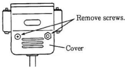
② Remove the wire short-circuited between terminals 2 and 3 and connect this wire to terminal 2 only. Or remove either one of the wires connected to terminal 3 and connect that wire to terminal 2 only. Do not change any other wiring.
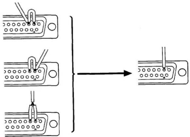
③ There are some open wires. Connect one of these wires to terminal 3. Choose a wire that is easily distinguishable.
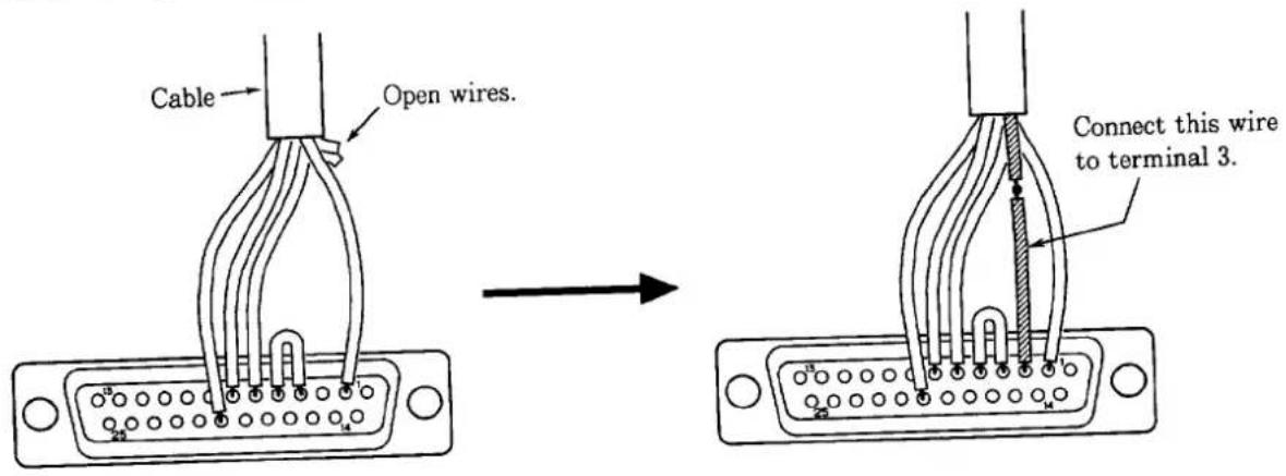
④ Mount the cover on the connector.
⑤ Remove the communication box cover.
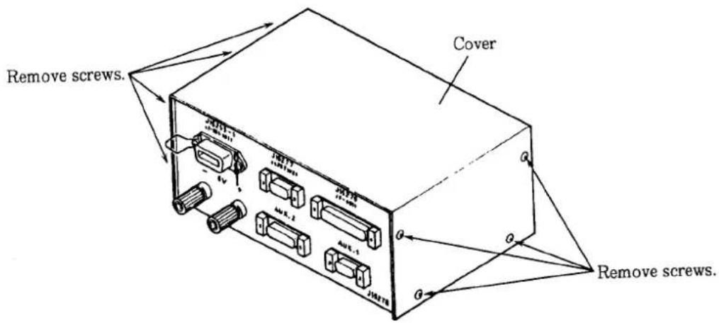
⑥ Make two holes at the positions as shown in the figure below and mount the switch.
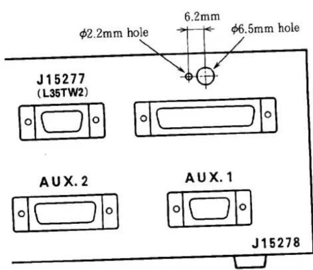
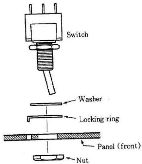
⑦ Connect wires inside the communication box as shown in the figure below. Do not change any other wiring.
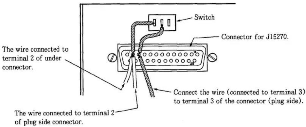
⑧ Remount the cover on the communication box.
⑨ For identification, put letters at the location as shown in the figure below.
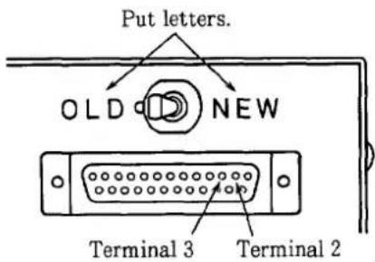
Note: Terminals 2 and 3 are short-circuited when the switch lever is turned toward "OLD" side, and terminals 2 and 3 are open when the switch lever is turned toward "NEW" side.
- How to use J15315
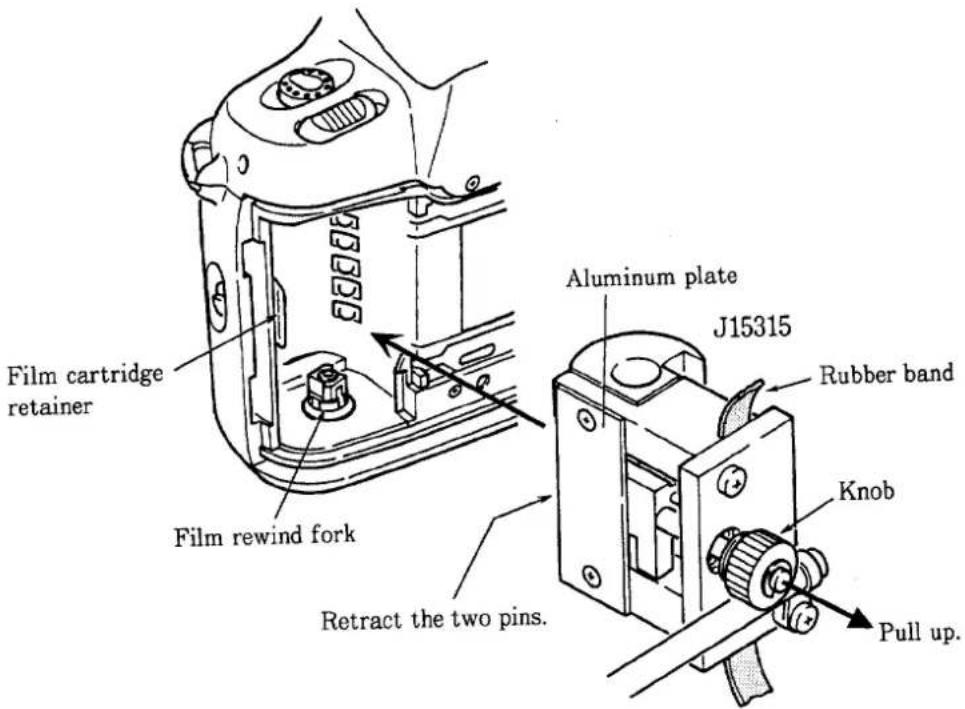
① Pull up the tool knob and retract the two pins in the tool.
Note: Pull up the knob to make the click mechanism effective. If it does not become effective, make an arrangement of wires connected to the two pins.
② Holding down the film rewinf fork, attach the tool to the camera.
Note: Make sure that tha film cartridge retainer does not protrude inside the tool's aluminum plate.
③ Secure the tool using a rubber band.
Inspection: Check to confirm that the tool is attached securely.
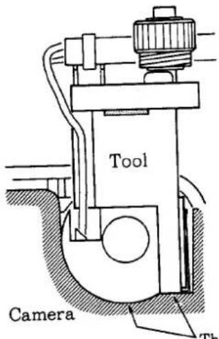
There should not be a gap between the camera and the tool.
④ The two pins are not used in the F50/N50, always retract them in the tool.
⑥ Attach the tool connector to the communication box.
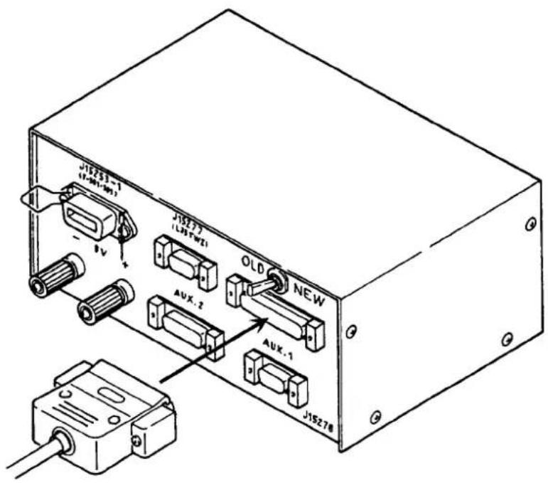
⑦ Set the switch on the communication box to "OLD".
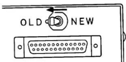
⑧ Start the "checking and adjustment programs". Then follow the instructions appearing the computer display.
5. Others
- When using conventional communication tool J15270, set the switch on the communication box to "OLD".
- This tool can also be used for both the F-401 and F-601 series cameras. When using tool, set the switch to "OLD" and retract the two pins.
- When using this tool for the F-801/N8008 series and F90/N90 cameras, make the following modifications.
① Disassemble the tool and cut the aluminum plate and plastic block to the dimensions shown in the figure below.
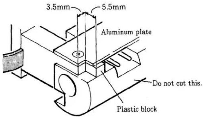
② Set the switch to "OLD".
③ Retract the two pins.
- Remove the two screws when replacing rubber band.
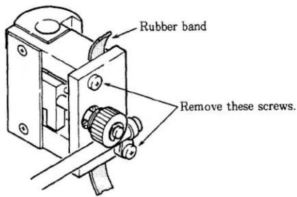
- Retract the two pins until instructed later.
| 作成承認印 | 配布許可印 |
 |  |
Nikon F50
FAA29051
F50D
FAA29251
N50
FAA29151
PARTS LIST
修理部品表
Nikon
NIKON CORPORATION
Tokyo, Japan
© Copyright 1994
ALL RIGHTS RESERVED
無断転載を禁ず!!
| 作成承認印 | 配布許可印 |
 |  |
NikonF50
FAA29051
F50D
FAA29251
N50
FAA29151
PARTS LIST (REVISED-1)
修理部品表(改訂-1)
Nikon
NIKON CORPORATION
Tokyo. Japan
Jun. 1. 1994
© Copyright 1994 ALL RIGHTS RESERVED 無断転載を禁ず!!
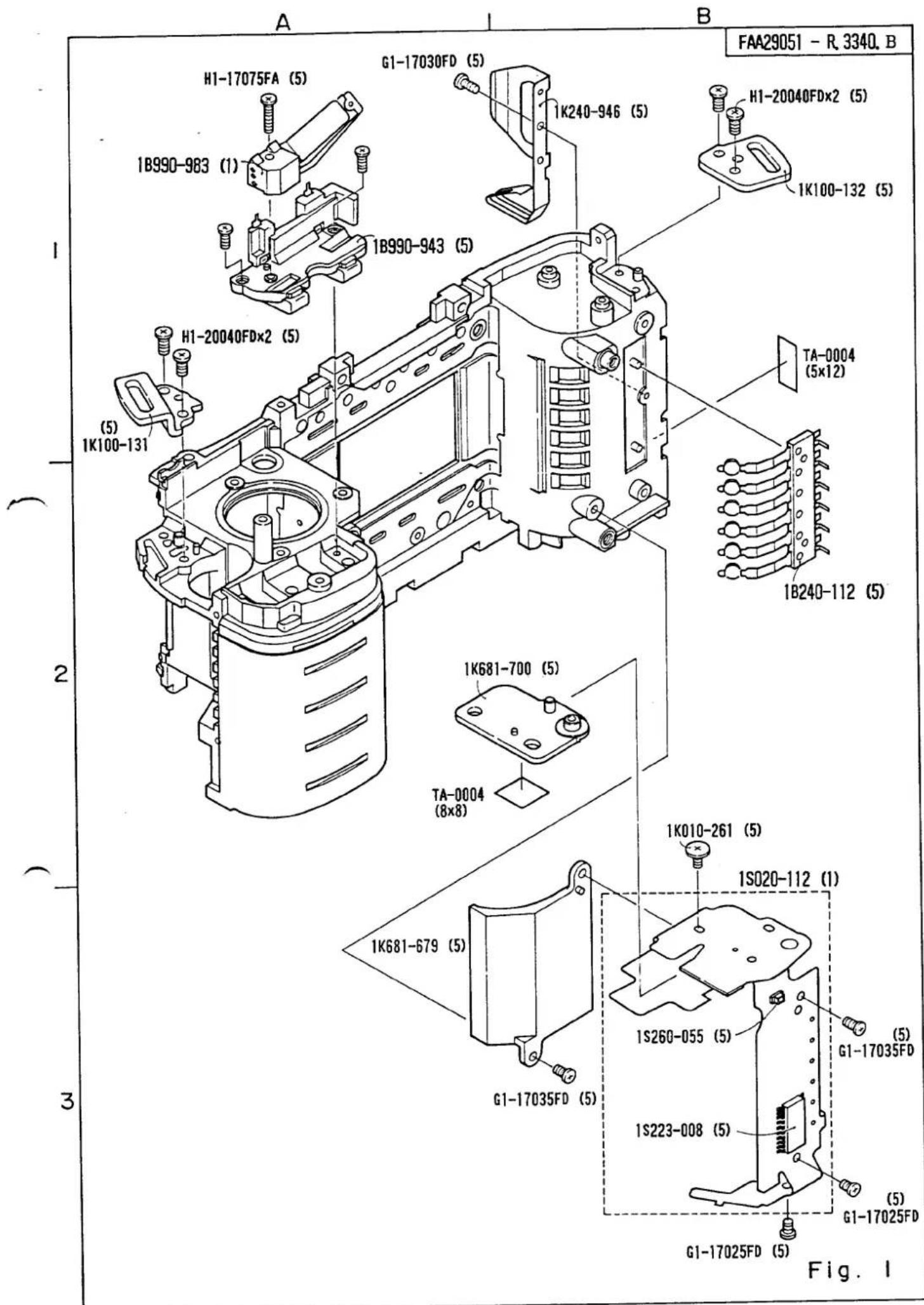

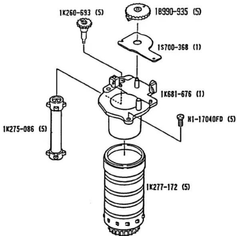
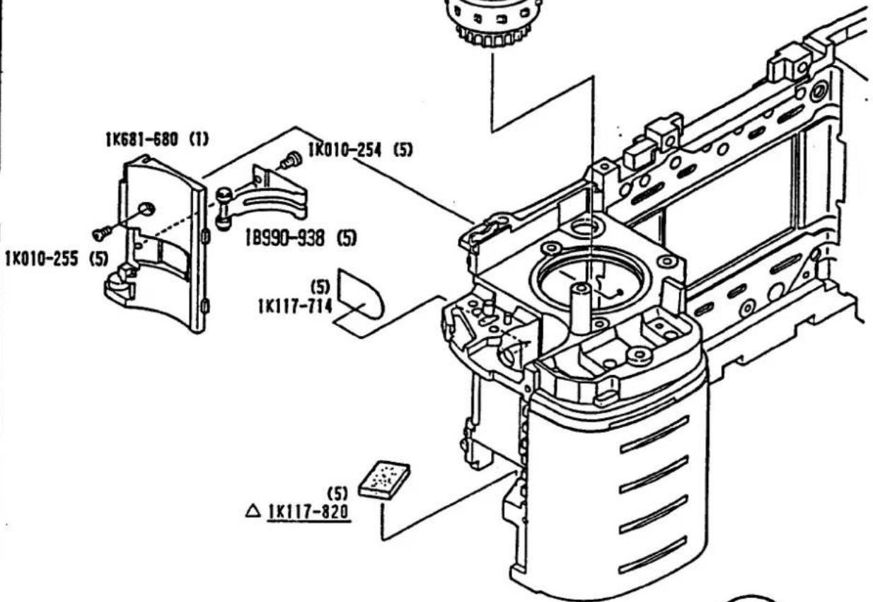
Fig. 2
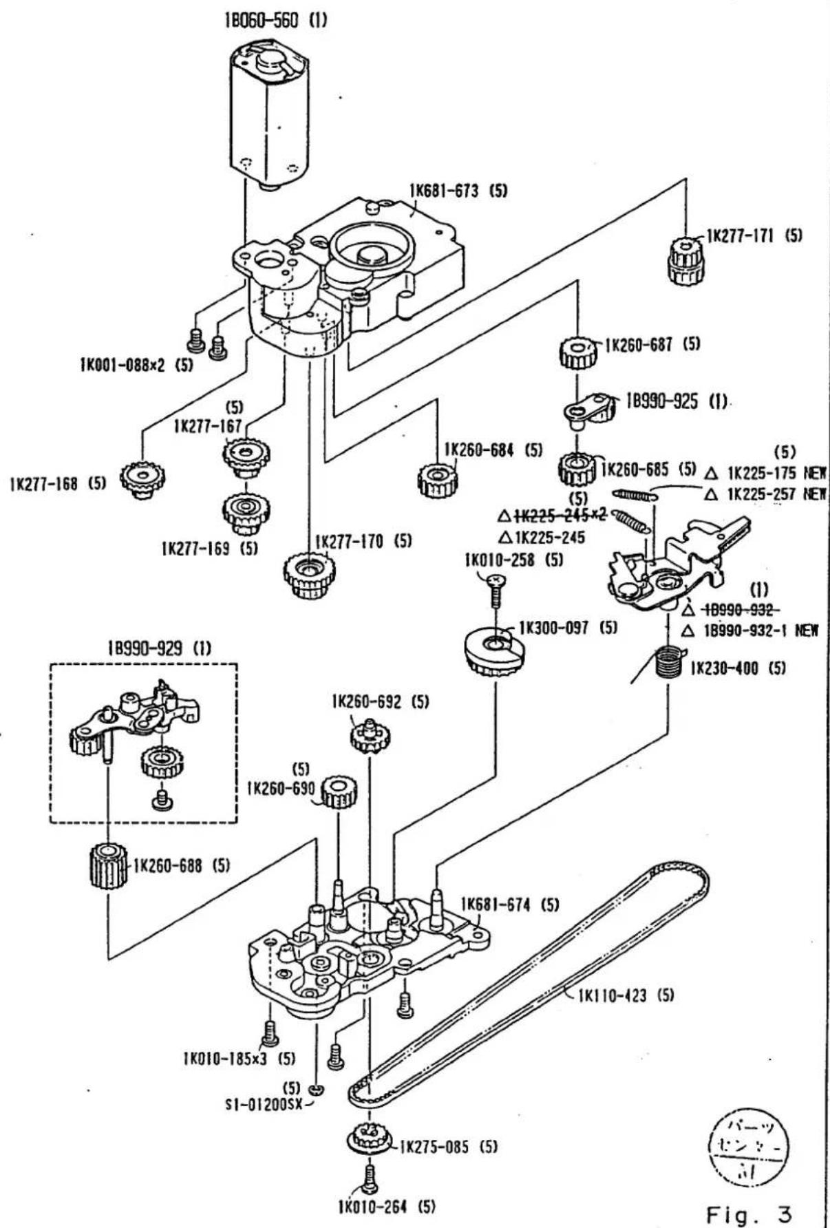
(1)
1B990-988
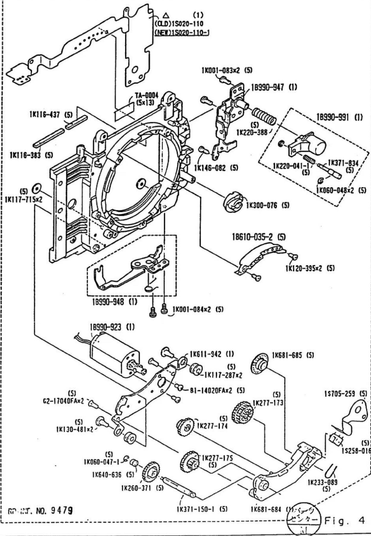
(1)
1B990-988
FAA29051 - R 3340. B
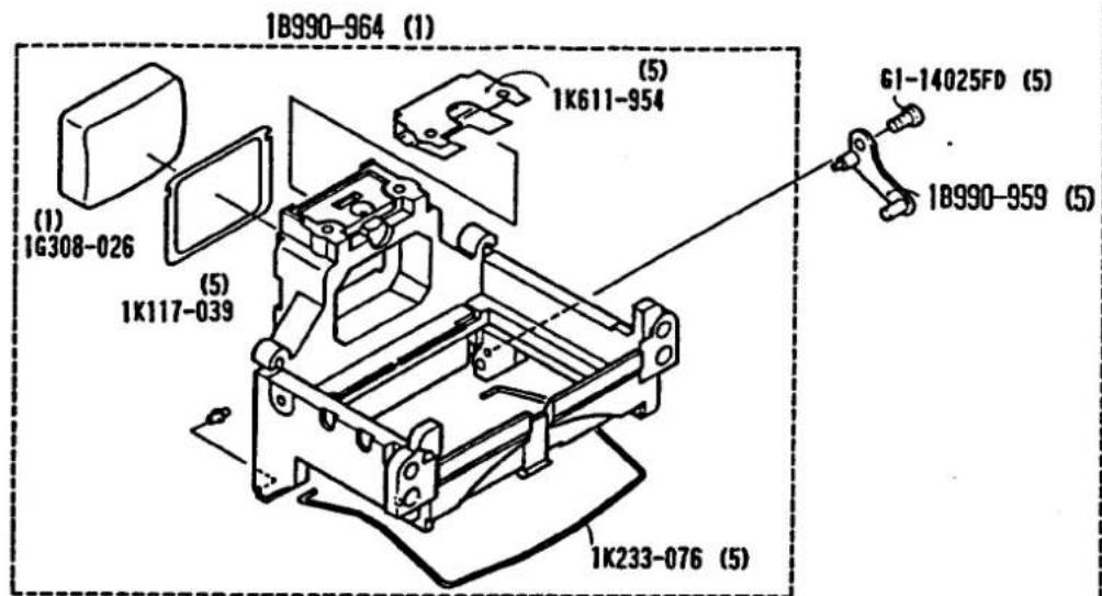
16571-008 (1)
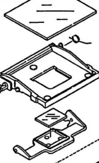
natural_image
Technical line drawing of a mechanical assembly with no visible text or symbols1B990-981 (1)
1K010-257×2 (5)
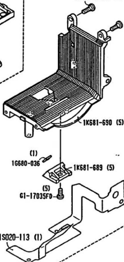
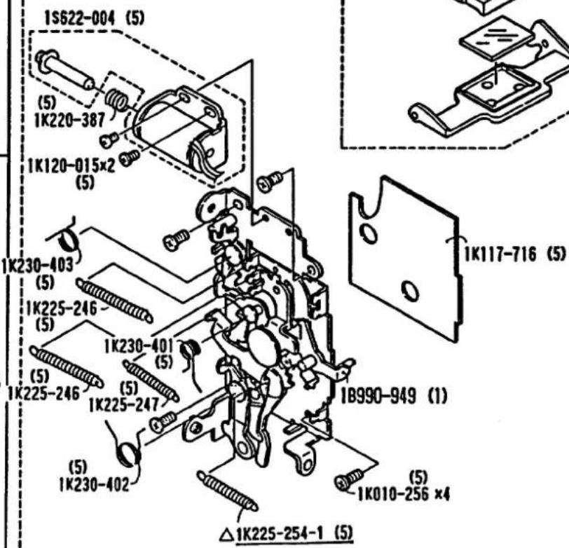

Fig. 5
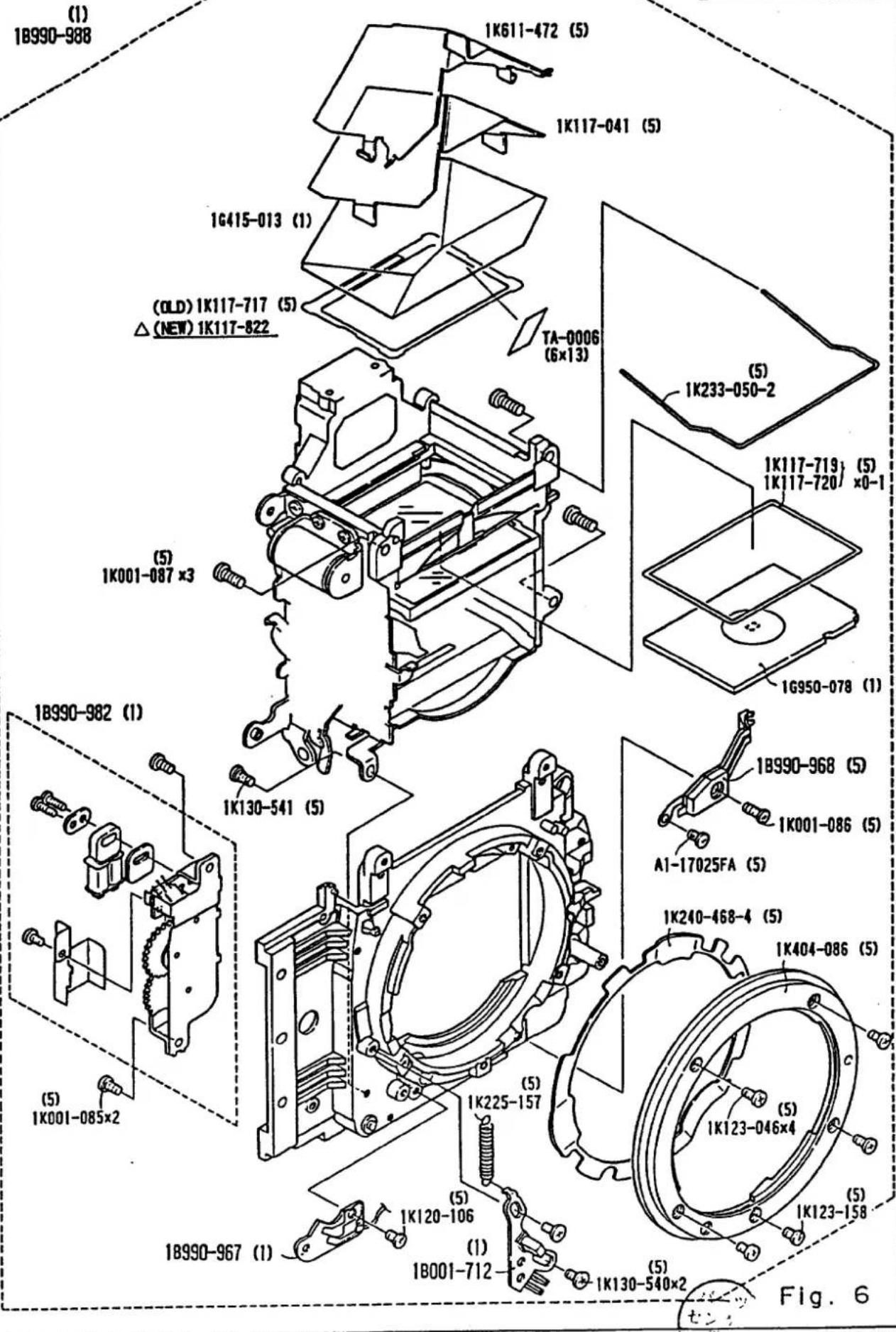
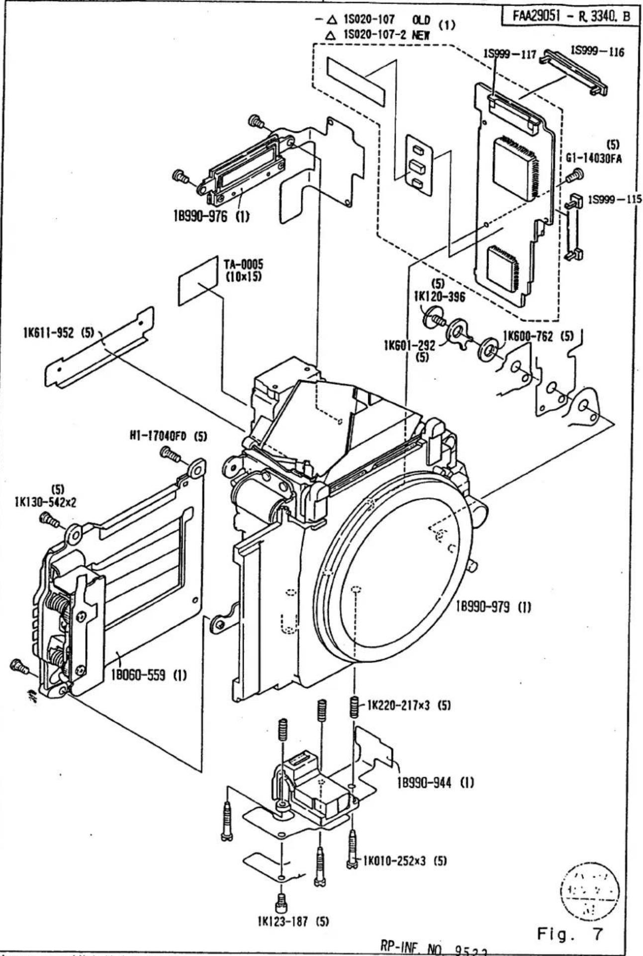
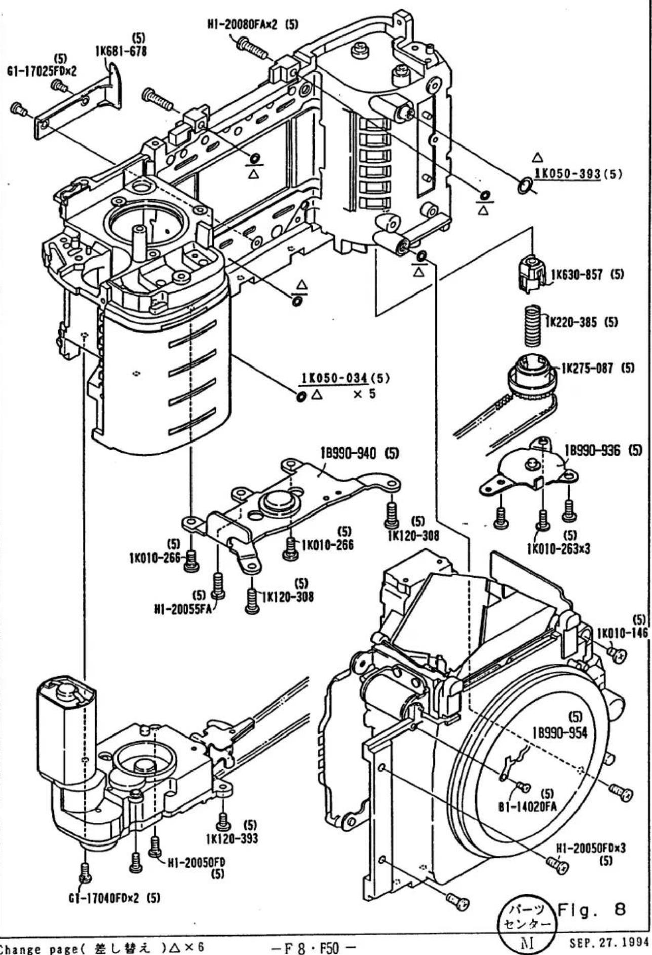
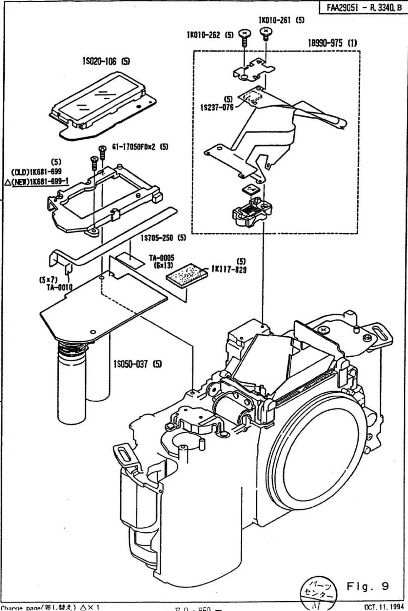
A
B
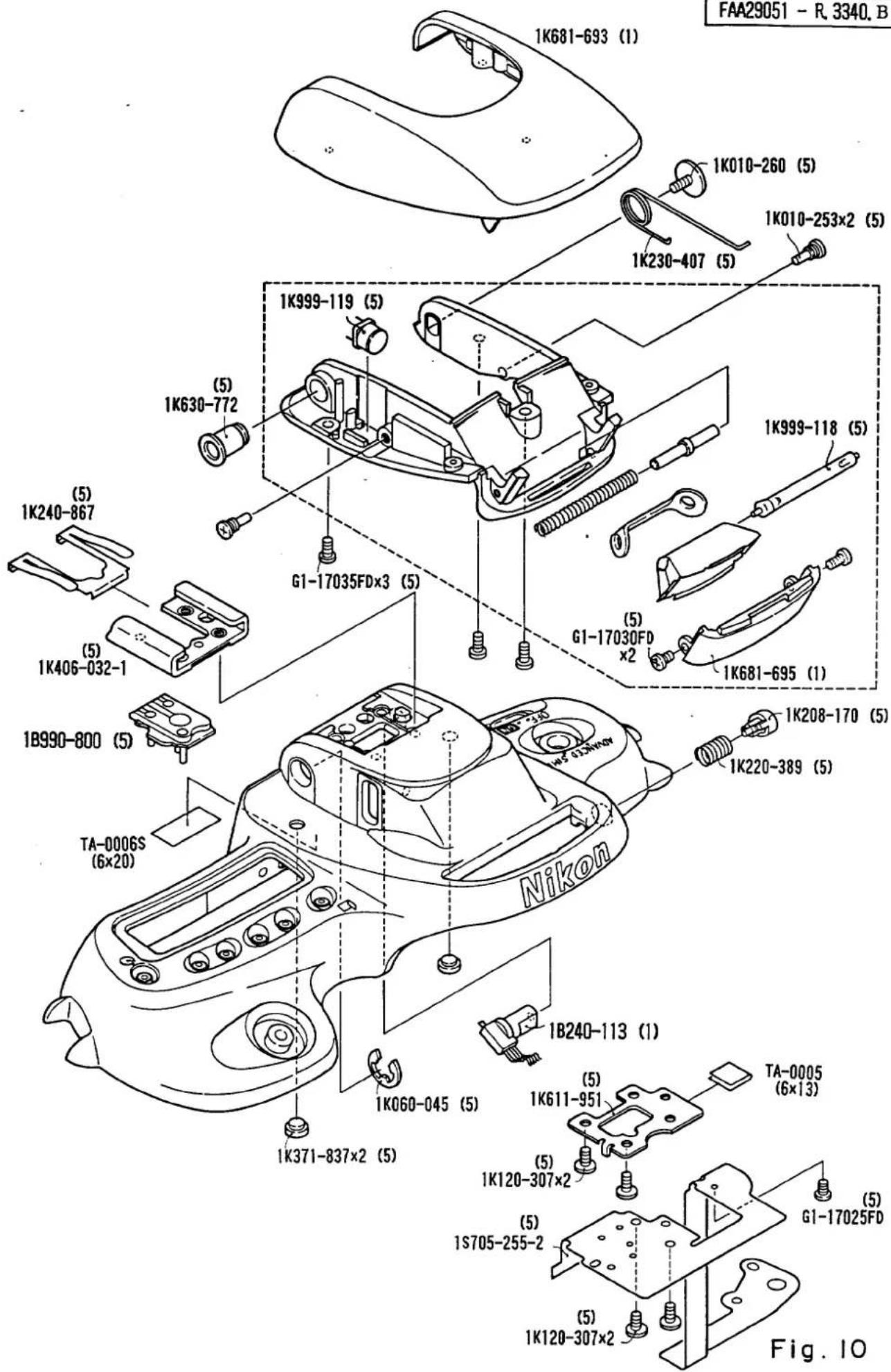
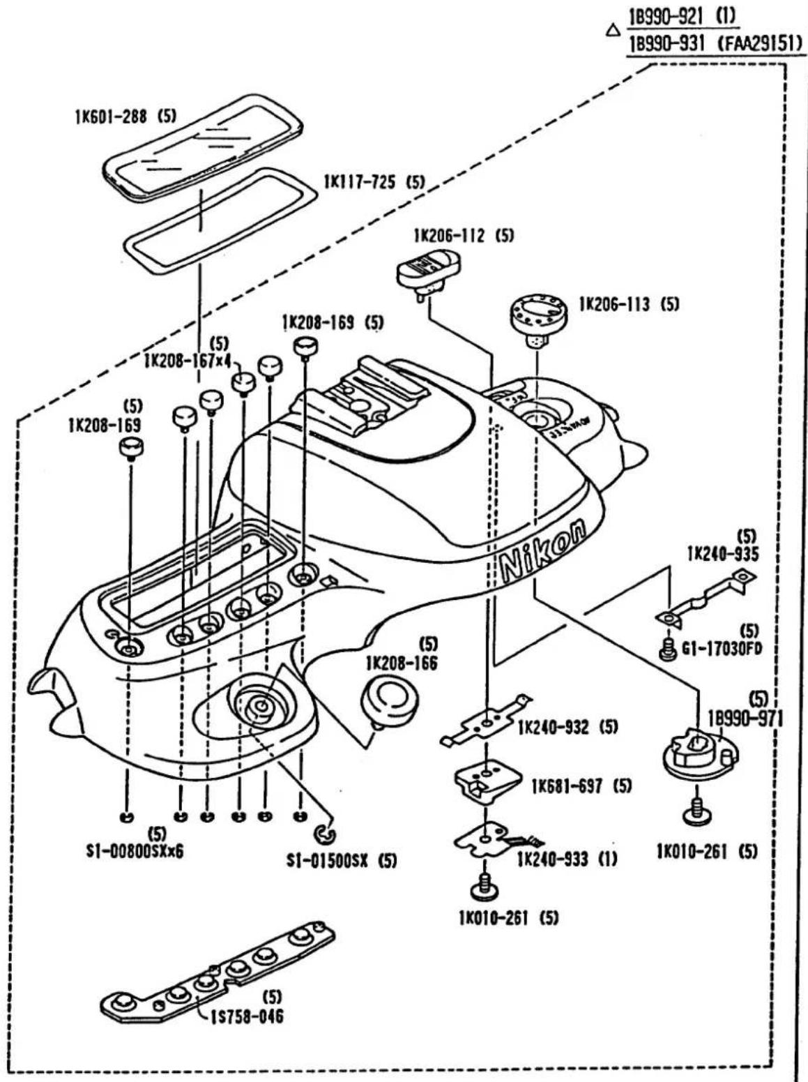

Fig. 11
18999-621-1 (1)
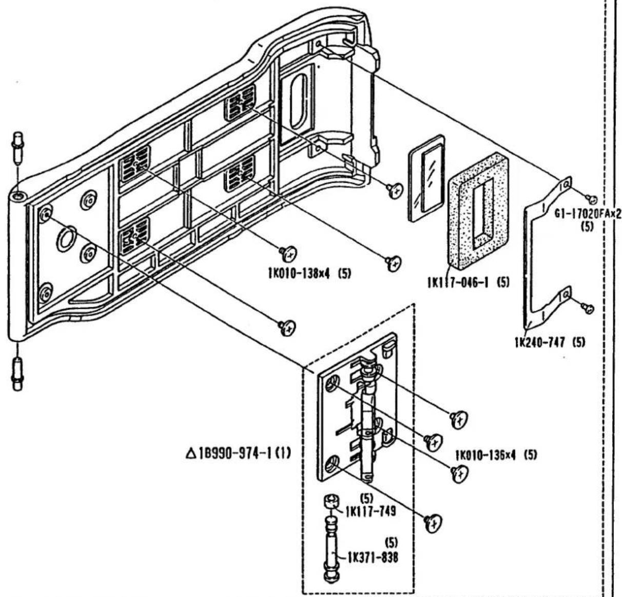
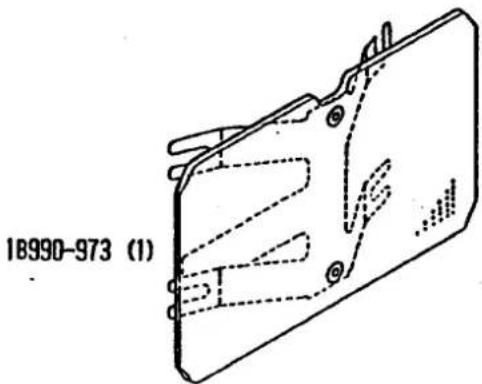
Fig. 12
Outline
1. Power Circuit
Block diagram of the power circuit is shown in Fig. 1. There are three power lines in the system.
(1) Vbat -- Battery voltage. Input power of DC-DC converter for driving motor and magnet systems.
(2) Vcc — Output power of DC-DC converter (approx. 5V) for driving the whole system other than CPU.
(3) Vdd-- Output power of Vbat through the 5V regulator and Vcc connected in parallel through diodes for driving the main CPU.
When the power is OFF, the Vdd is applied to the main CPU only, and the CPU is in the stand-by state. When the main switch or power activating switch is turned ON from the OFF state, the CPU goes into "RUN" state and activates the DC-DC converter to generate Vcc output. As Vcc applied to each IC, it becomes activated. As described above, voltage is applied to the CPU in the stand-by state even though the main switch is turned is turned OFF.
2. Components
U1(main CPU) — Performs all operations including AE calculation and control, AF calculation and control, shutter release sequence, and communication controls.
U2(AF-IF) — Interacting AF signal (or transmitting information) from CCD(U7) to CPU. Sending control codes from the CPU through a decoder circuit to drive magnets or motors by operating each latch circuit.
U5(metering IC) -- IC element combining 6-segment SPD with its head amplifier sealed in transparent mold. Transmitting 6-segment metering data to the CPU in time sequence.
U8(TTL-IC)-ic element combining SPD for TTL metering with its metering circuit sealed in transparent mold. Outputting flash firing halt signal using the output signal from CPU-AP IF-TTL-IC and D/A converter and photoelectric current from the SPD.
LCD module—Displaying specified information on the dotmatrix external LCD panel through serial communication from CPU.
3. Shutter release sequence
Outline of sequence time chart is shown in Fig. 3.
(1) When shutter release switch is kept ON for more than 20 ms, the camera enters into shutter release sequence.
(2) A signal is first sent to the release Mg to start shutter release operation. At the same time a signal is sent to front and rear shutter curtain Mgs to hold the shutter curtains.
(3) Aperture pulses are counted and a signal is sent to the aperture Mg when the number of pulses reaches the specified number depending on aperture setting. This stops aperture control operation.
(4) Front curtain operation is released is approx. 70ms after sending signal to the release Mg. In specified shutter time, the rear curtain operation is released. When detecting X contact ON signal, the Triac is turned ON immediately.
(5) In approximately 20 ms after running shutter curtains, film advance motor starts rotating and moves the mirror down and advance the film. When receiving 8 pulses from the sprocket a switch signal is sent back as a film advance completion signal to the film advance motor to brake the motor.
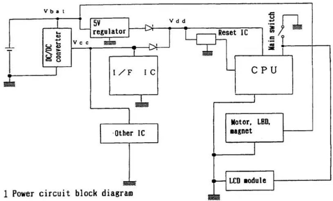
flowchart
graph TD
    A["DC/DC converter"] -->|Vbat| B["5V regulator"]
    B --> C["Reset IC"]
    C --> D["CPU"]
    D --> E["Motor, LBD, magnet"]
    E --> F["LCD module"]
    F --> G["Main switch"]
    H["I/F IC"] --> I["Other IC"]
    I --> J["Vcc"]
    J --> B
    K["Vdd"] --> C
    style A fill:#f9f,stroke:#333
    style B fill:#ccf,stroke:#333
    style C fill:#cfc,stroke:#333
    style D fill:#fcc,stroke:#333
    style E fill:#cff,stroke:#333
    style F fill:#ffc,stroke:#333
    style G fill:#fcc,stroke:#333
    style H fill:#fff,stroke:#333
    style I fill:#fff,stroke:#333
    style J fill:#fff,stroke:#333
    style K fill:#fff,stroke:#333
    style_L["Ground"] --> M["Vcc"]
Fig. 1 Power circuit block diagram
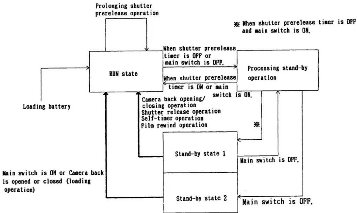
flowchart
graph TD
    A["RUN state"] -->|Prolonging shutter prerelease operation| B["Processing stand-by operation"]
    B -->|When shutter prerelease timer is OFF or main switch is OFF.| C["Main switch is ON or Camera back is opened or closed (loading operation)"]
    B -->|When shutter prerelease timer is ON or main| D["Main switch is OFF."]
    D --> E["Stand-by state 1"]
    E --> F["Main switch is ON or Camera back"]
    E --> G["Stand-by state 2"]
    G --> H["Loading battery"]
    H --> A
    style A fill:#f9f,stroke:#333
    style B fill:#ccf,stroke:#333
    style E fill:#cfc,stroke:#333
    style G fill:#fcc,stroke:#333
Fig. 2 CPU state transition diagram
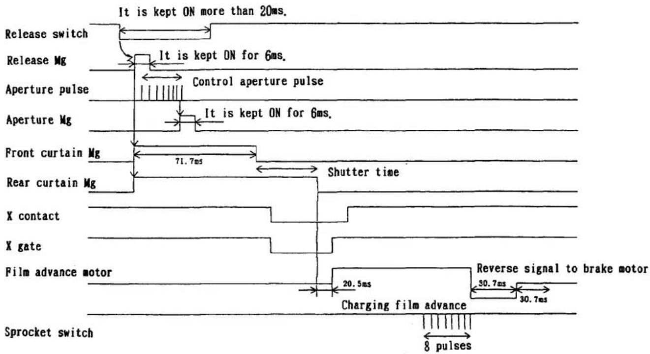
flowchart
graph TD
    A["Release switch"] --> B["Release Mg"]
    B --> C["Aperture pulse"]
    C --> D["Front curtain Mg"]
    D --> E["Rear curtain Mg"]
    E --> F["X contact"]
    F --> G["X gate"]
    G --> H["Film advance motor"]
    H --> I["Sprocket switch"]

    subgraph Timeframe
        J["It is kept ON more than 20ms."]
        K["It is kept ON for 6ms."]
        L["Control aperture pulse"]
        M["It is kept ON for 6ms."]
        N["Shutter time"]
        O["Reverse signal to brake motor"]
        P["Charging film advance"]
        Q["8 pulses"]
    end

    style J fill:#f9f,stroke:#333
    style K fill:#f9f,stroke:#333
    style L fill:#f9f,stroke:#333
    style M fill:#f9f,stroke:#333
    style N fill:#f9f,stroke:#333
    style O fill:#f9f,stroke:#333
    style P fill:#f9f,stroke:#333
    style Q fill:#f9f,stroke:#333
Fig. 3 Shutter release sequence time chart
Switch Table
| NO | Name | Code | CPU | NO | Name | Code | CPU |
| 1 | Release Switch | RLS | 44p | 11 | MENU Switch | MNU | 41p |
| 2 | Pre-Release Switch | HAN | 39p | 12 | Setting Switch 1 | ST1 | 15p |
| 3 | Sprocket Switch | SPRO | 88p | 13 | Setting Switch 2 | ST2 | 16p |
| 4 | Syncro Switch | XSW | 43p | 14 | Setting Switch 3 | ST3 | 17p |
| 5 | Power Swtich | POWSW | 38p | 15 | Setting Switch 4 | ST4 | 18p |
| 6 | Mode Switch | MODE | 37p | 16 | A E -Lock Switch | AEL | 51p |
| 7 | Rewind Switch | REW | 36p | 17 | A F Switch | AFSW | 49p |
| 8 | Camera Back Switch | UBSW | 42p | 18 | FMN SW | FMIN | 78p |
| 9 | Built-in Flash SW | SBSW | 50p | — | —— | —— | — |
| 10 | Self Timer Switch | SSW | 40p | — | —— | —— | — |
SW — Switch
I C pin number
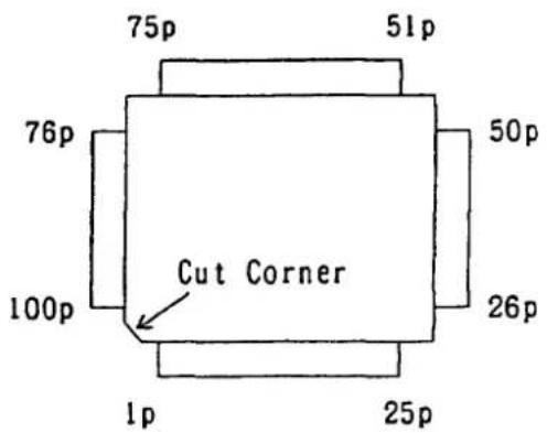
Mein CPU Pin Number
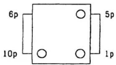
MeteringIC.TTL-IC Pin Number
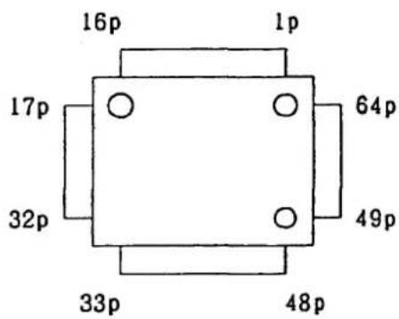
AF-IF Pin Number
CPU (H8 3834) Pin Name Table
| NO | PORT | Name | Connect | Land |
| 1 | PC3 | Battery Check Input | →C1,R3,R4 | TP-1 |
| 2 | AVss | AGND | ||
| 3 | TEST | DGND | ||
| 4 | X2 | NC | ||
| 5 | X1 | Vdd | ||
| 6 | Vss | DGND | ||
| 7 | OSC1 | System Clock 1 8 MHz | →FAR,R13 | |
| 8 | OSC2 | System Clock 2 8 MHz | →FAR,R13 | |
| 9 | RES | Reset Input | →U9 1p,R18 | TP-RES |
| 10 | MDO | Vdd | ||
| 11 | P20 | AGC/STB | →U2 12p | TP-AGC |
| 12 | P21 | Charge Signal | →Q3C,R16 (L is Charged) | TP-12 |
| 13 | P22 | Stop Signal 1 | →U8 7p,D202→Stop | TP-STP |
| 14 | P23 | DX 3 | →R715 | TP-DX3 |
| 15 | P24 | Setting Switch 1 | →R201, Setting Switch 1 | TP-ST1 |
| 16 | P25 | Setting Switch 2 | →R201, Setting Switch 2 | TP-ST2 |
| 17 | P26 | Setting Switch 3 | →R201, Setting Switch 3 | TP-ST3 |
| 18 | P27 | Setting Switch 4 | →R201, Setting Switch 4 | TP-ST4 |
| 19 | P30 | Lens Contact(SCK) | →R401→Lens C Contact | TP-SCK1 |
| 20 | P31 | Lens Contact (SI) | →R401→Lens D Contact | TP-SIO |
| 21 | P32 | Lens Contact (SO) | P31 | |
| 22 | P33 | E2PROM SCL,LCD DriveSCK | →U3 6p,LCD Driver (SCK) | TP-SCK |
| 23 | P34 | E2PROM SDA Data in | →U3 5p,R8,LCD Driver (SO) | TP-SO |
| 24 | P35 | E2PROM SDA,LCD Driver SO | P34 | |
| 25 | P36 | LCD Driver (CSI) | →LCD Driver (CSI) | TP-CS1 |
| 26 | P37 | STB | →U2 10p | TP-STB |
| 27 | Vss | GND | ||
| 28 | V3 | Power for LCD | →R7 | TP-28 |
| 29 | V2 | Power for LCD | →R7,R6 | TP-29 |
| 30 | V1 | Power for LCD (Vcc) | ||
| 31 | Vdd | Vdd | ||
| 32 | PA3 | Finder LCD Common 4 | →Finder LCD COM4 | TP-COM4 |
| 33 | PA2 | Finder LCD Common 3 | →Finder LCD COM3 | TP-COM3 |
| 34 | PA1 | Finder LCD Common 2 | →Finder LCD COM2 | TP-COM2 |
| 35 | PAO | Finder LCD Common 1 | →Finder LCD COM1 | TP-COM1 |
| 36 | WKPO | Rewind Switch Input | →Rewind Switch | TP-REW |
| 37 | WKPI | Mode Switch Input | →Mode Switch | TP-MODE |
| 38 | WKPI2 | Power Switch Input | →Mein Switch,R19,LCD EN1 | TP-POSW |
| 39 | WKPI3 | Pre-release Input | →Pre-release Switch | TP-HAN |
| 40 | WKPI4 | Self-Timer Switch Input | →Self-Timer Switch | TP-SSW |
| 41 | WKPI5 | MENU Switch Input | →MENU Switch Input | TP-MNU |
| 42 | WKPI6 | Camera Back Switch Input | →Camera Back Sw(H is open) | TP-URSW |
| 43 | WKPI7 | Syncro Switch Input | →Syncro Switch(X SW) | TP-XSW |
| 44 | P60 | Release Switch Input | →Release Switch | TP-RLS |
| 45 | P61 | Ready Signal Built in SB | →READDY for Built in SB | TP-RDY |
| 46 | P62 | SB Power-ON Signal | →Q3 C | TP-46 |
| 47 | P63 | NC | ||
| 48 | P64 | DX 6 | →R701→DX 6 | TP-DX6 |
| 49 | P65 | AF-A/M SW (LisMF,HisAF) | →AF SW (A/M) | TP-AFSW |
| 50 | P66 | Pop-up Input (UPisL) | →Built in SB Switch | TP-SBSW |
| 51 | P67 | AE Lock Switch | →A EL Switch | TP-AEL |
| 52 | P70 | Latch Code Output φ | →U2 8p | TP-D0 |
| 53 | P71 | Latch Code Output 1 | →U2 7p | TP-D1 |
| 54 | P72 | Latch Code Output 2 | →U2 6p | TP-D2 |
| 55 | P73 | Latch Code Output 3 | →U2 5p | TP-D3 |
| 56 | P74 | Latch Code Output 4 | →U2 4p | TP-D4 |
| 57 | P75 | Latch Code Output 5 | →U2 3p | TP-D5 |
| 58 | P76 | Latch Code Output 6 | →U2 2p | TP-D6 |
| 59 | P77 | ChangeSignal Latch orD/A | →U2 1p | TP-S1 |
| 60 | P80 | Metering IC Chip Select | →U5 7p | TP-CS |
| 61 | P81 | Metering IC Data Clock | →U5 10p | TP-CLK |
| 62 | P82 | Metering IC Range Change | →U5 5p | TP-LS |
| 63 | P83 | Metering IC Charge | →U5 4p | TP-CHG |
| 64 | P84 | Finder LCD Segment2 | →Finder LCD SEG2 | TP-SEG2 |
| 65 | P85 | Finder LCD Segment3 | →Finder LCD SEG3 | TP-SEG3 |
| 66 | P86 | Finder LCD Segment4 | →Finder LCD SEG4 | TP-SEG4 |
| 67 | P87 | Finder LCD Segment5 | →Finder LCD SEG5 | TP-SEG5 |
| 68 | P90 | Finder LCD Segment1 | →Finder LCD SEG1 | TP-SEG1 |
| 69 | P91 | Finder LCD Segment6 | →Finder LCD SEG6 | TP-SEG6 |
| 70 | P92 | Finder LCD Segment7 | →Finder LCD SEG7 | TP-SEG7 |
| 71 | P93 | Finder LCD Segment8 | →Finder LCD SEG8 | TP-SEG8 |
| 72 | P94 | Finder LCD Segment9 | →Finder LCD SEG9 | TP-SEG9 |
| 73 | P95 | Finder LCD Segment10 | →Finder LCD SEG10 | TP-SEG10 |
| 74 | CL2 | Finder LCD Segment11 | →Finder LCD SEG11 | TP-SEG11 |
| 75 | CL1 | Finder LCD Segment12 | →Finder LCD SEG12 | TP-SEG12 |
| 76 | Vdd | Vdd | ||
| 77 | P10 | Clock Output | →U2 16p | TP-CLK |
| 78 | P11 | F-min Signal(L is Min) | →F min SW | TP-FMIN |
| 79 | P12 | DC-DC Control Signal | →Q202B, LCD EN2 | TP-CTL |
| 80 | P13 | AF PINT | →AF PhotoInter-rupterOutput | TP-AFPIO |
| 81 | P14 | PWM Output | →U2 15p | TP-PMH |
| 82 | P15 | Lens Contact(R/W 1) | →Lens B Contact | TP-RW1 |
| 83 | P16 | Ap PINT | →Ap PhotoInter-rupterOutput | TP-APPIO |
| 84 | P17 | P13 | ||
| 85 | P40 | DX 2 | →R716, DX2 | TP-DX2 |
| 86 | P41 | DX 5 | →R713, DX5 | TP-DX5 |
| 87 | P42 | DX 4 | →R714, DX4 | TP-DX4 |
| 88 | P43 | Sprocket Switch Input | →R203, Spro- SW | TP-SPRO |
| 89 | AVcc | 4 VRegulator Output | →R15, C11, U2 29 30p | TP-VREF1 |
| 90 | PBO | Metering IC Output | →U5 2p | TP-VOUT1 |
| 91 | PB1 | NC | ||
| 92 | PB2 | Built in Flash RTH | →R15, SB TH1 | TP-ATH |
| 93 | PB3 | CCD Output | →U2 33p | TP-AFOUT |
| 94 | PB4 | NC | ||
| 95 | PB5 | TTL Reference Voltage | →U8 2p | TP-VREF |
| 96 | PB6 | NC | ||
| 97 | PB7 | NC | ||
| 98 | PCO | NC | ||
| 99 | PC1 | NC | ||
| 100 | PC2 | TTL Output | →R5, D1 |
SI — Serial Input SO — Seruial Output SDA — Serial Data PWM — Puls Width Modulation Ap — Aperture PINT — Photo Interrupter R/W — Read Write Signal
AF IC (M50208FP) Pin Name Table
| NO | PORT | Name | Contact | Land |
| 1 | S1 | Select Bit 1 | →U1 59p | TP-S1 |
| 2 | D6 | Decoder input Bit 6 | →U1 58p | TP-D6 |
| 3 | D5 | Decoder input Bit 5 | →U1 57p | TP-D5 |
| 4 | D4 | Decoder input Bit 4 | →U1 56p | TP-D4 |
| 5 | D3 | Decoder input Bit 3 | →U1 55p | TP-D3 |
| 6 | D2 | Decoder input Bit 2 | →U1 54p | TP-D2 |
| 7 | D1 | Decoder input Bit 1 | →U1 53p | TP-D1 |
| 8 | DO | Decoder input Bit φ | →U1 52p | TP-DO |
| 9 | DGND | D G N D | ||
| 10 | STB | Latch Timing Signal | →U1 26p | TP-STB |
| 11 | NC | N C | ||
| 12 | AGC | HardAGC(ChargeComplet) | →U1 11p | TP-AGC |
| 13 | TTL | T T L Current Source | →D1→R705→Hot SHue TTL | TP-TTL1 |
| 14 | RESET | N C | ||
| 15 | PWMIN | PWM Input | →U1 81p | TP-PWMI |
| 16 | CLKIN | 1.25MHz Input | →U1 77p | TP-CLK |
| 17 | Vcc | V c c | ||
| 18 | CHTOUT | N C | ||
| 19 | CHTIN | N C | ||
| 20 | NC | N C | ||
| 21 | TM1 | TrigerSignal 1 | →Built in Flash TrigerSignal | TP-STA |
| 22 | SBPOUT | ChargeSignal for SB | →Built in Flash OSC Signal | TP-SBCHG |
| 23 | SBPIN | BatteryCheck Signal | →R1, R2 | |
| 24 | PL1 | ApPINT Driver | →ApPhotoInterrupter K | TP-APPIC |
| 25 | MG3 | Ap Mg Drive Signal | →Q401B(Ap Mg Drive) | TP-APMG |
| 26 | DB | Data Print Signal | →Data Back Contact | TP-DB |
| 27 | PL2 | AF PINT Drive | →R403→AF PhotoInterrupter K | TP-APPIC |
| 28 | IS | Integrate Start Signal | →U8 1p | TP-IS |
| 29 | VREFIN | 4 V Input(Rference V) | →C11, U1 39p, R15 | TP-VREF1 |
| 30 | VRFOUT | 4 V Regulator Output | Connect to "VREFIN" | |
| 31 | D/A | D/A Output | →U8 3p | TP-DA |
| 32 | AVcc | A V c c | ||
| 33 | AFOUT | A F Signal Output | →U1 33p | TP-AFOUT |
| 34 | COBB | Sample Hold C(B) | →C7 | |
| 35 | COBA | Sample Hold C(A) | →C8 | |
| 36 | VB2 | N C | ||
| 37 | VB1 | N C | ||
| 38 | VBIN | CC D Signal B | →U7 1p | TP-VOUTB |
| 39 | VA2 | N C | ||
| 40 | VA1 | N C | ||
| 41 | VAIN | CC D Signal A | →U7 6p | TP-VOUTA |
| 42 | AGCM | A G C Control | ||
| 43 | AGC | N C | ||
| 44 | AGND | G N D | ||
| 45 | QTG | Carry Timming Signal | →U7 12p | TP-TG |
| 46 | QCG | Clear Timming Signal | →U7 13p | TP-CG |
| 47 | QC | Clock | →U7 14p | TP-C |
| 48 | QRA | Charge Level(A) | →U7 15p | TP-RA |
| 49 | QRB | Charge Level (B) | →U7 16p | TP-RB |
| 50 | CM1 | CCD GainAdjustOutput | →U7 5p | TP-OG |
| 51 | PIKAPI | Focusing Light Output | →HotShue RDY,R9,R11 | TP-RDY1 |
| 52 | TM2 | SB Triger Signal | ||
| 53 | PWM1 | Motor Driver Output 1 | →U6 10p | TP-PWM1 |
| 54 | PWM2 | Motor Driver Output 2 | →U6 8p | TP-PWM2 |
| 55 | PWM3 | Motor Driver Output 3 | →U6 9p | TP-PWM3 |
| 56 | ILM | Illuminator Control | →Q601B(IliminatorLED Drive) | TP-ILM |
| 57 | CM2 | NC | ||
| 58 | CM3 | NC | ||
| 59 | TM3 | NC | ||
| 60 | TM4 | →Q701B(TRIAC Drive) | TP-SYNC | |
| 61 | MG2 | →Q205B(2ndCertainMagnetDrive) | TP-RMG | |
| 62 | MG1 | →Q205B(1stCertainMagnetDrive) | TP-FMG | |
| 63 | TM5 | →Q203B(Release MagnetDrive) | TP-RLSMG | |
| 64 | TM6 | →R703→LED for Self-Timer | TP-SELF |
Mg —— Magnet
TTL IC (M52961FP) Pin Name Table
| NO | PORT | Name | Contact | Land |
| 1 | IS | IntegrateStartSignal | →U2 28p | TP8-IS |
| 2 | VREF | ReferenceVoltage | →U1 93p | TP8-VREF |
| 3 | DA | Gain Select Voltage | →U2 31p | TP8-DA |
| 4 | AGND | A G N D | ||
| 5 | NC | |||
| 6 | STOP1 | Stop Signal 1 | →R706→HotShue STOP | TP8-STOP1 |
| 7 | STOP2 | Stop Signal 2 | →U1 13p.D202 →Built in SB | TP8-STOP2 |
| 8 | Vcc | A V C C | ||
| 9 | SC | Condenserfor Integrate | →C802 | |
| 10 | DGND | D G N D |
MeteringIC(M52960FP) Pin Name Table
| NO | PORT | Name | Contact | Land |
| 1 | NC | Reference Voltage | N C | |
| 2 | VOUT | Metring Output | →R204→TP-VOUT1→U1 90p | TP2-VOUTA |
| 3 | AVCC | A V C C | TP2-AVCC | |
| 4 | CHG | ChargeSignalto HeadAmp | →TP-CHG→U1 63p | TP2-CHG |
| 5 | LS | Range Change Signal | →TP-LS →U1 62p | TP2-LS |
| 6 | NC | Test Mode Signal | N C | TP2-TEST |
| 7 | CS | Channel Select Signal | →TP-CS →U1 60p | TP2-CS |
| 8 | DGND | D G N D | ||
| 9 | AGND | A G N D | TP2-AGND | |
| 10 | CLK | Channel Select Clock | →TP-CLK→U1 61p | TP2-CLK |
Check Land Table
cf. — TP is for "Test Point". CN is for "Connector". WL is for "Wirering". AS is for ".AS is for"ASSETSU(means contact for face to face)".
POS. is indicated the position of Test Point on the figure of PCB.
Main PCB (Face)
| Land Name | Signal Name | Connect | POS. |
| TP-1 | Battery Check Input | U1 1p←→C1,R3,R4 | C 2 |
| TP-12 | ChargeSignal(L is Charged) | U1 12p←→R16,Q3C 1/2 | C 2 |
| TP-28 | Power for LCD | U1 28p←→Center of R7 | B 2 |
| TP-29 | Power for LCD | U1 29p←→R6,R7 | B 2 |
| TP-46 | S B Power ON Signal | U1 46p←→Q3C 2/2 | B 2 |
| TP-AEL | A E Lock Switch | CN2-AEL←→U1 51p | D 1 |
| TP-BAT2 | Battery Voltage | →V b a t | B 2 |
| TP-C | Carry Clock | U2 47p←→CN3-C | A 2 |
| TP-CG | Clear Timming | U2 46p←→CN3-CG | A 2 |
| TP-CHG | Metring IC Charge Signal | U1 63p←→CN2-CHG | C 3 |
| TP-CTL | DC-DC Control | U1 79p←→CN2-CTL | C 2 |
| TP-D0 | Latch Code 0 | U2 8p←→U1 52p | B 2 |
| TP-D1 | Latch Code 1 | U2 7p←→U1 53p | |
| TP-D2 | Latch Code 2 | U2 6p←→U1 54p | |
| TP-D3 | Latch Code 3 | U2 5p←→U1 55p | |
| TP-D4 | Latch Code 4 | U2 4p←→U1 56p | |
| TP-D5 | Latch Code 5 | U2 3p←→U1 57p | |
| TP-D6 | Latch Code 6 | U2 2p←→U1 58p | ↓ |
| TP-DGND1 | Digital G N D | →D G N D | C 2 |
| TP-DX4 | DX 4 Contact | U1 87p←→CN7-DX4 | C 2 |
| TP-DX6 | DX 6 Contact | U1 48p←→CN7-DX6 | C 3 |
| TP-FMG | 1st Magnet Drive Signal | U2 52p←→CN2-FMG | A 2 |
| TP-HAN | Pre-release Switch | U1 39p←→CN2-HAN,CN7-HAN | B 2 |
| TP-LS | Metring Range Change | U1 62p←→CN2-LS | C 3 |
| TP-NS1 | B 1 | ||
| TP-NS2 | B-C2 | ||
| TP-OG | CC D OG Signal | U2 50p←→CN3-OG | A 2 |
| TP-RA | CC D RA Signal | U2 48p←→CN3-RA | A 2 |
| TP-RES1 | U9 Input | U9 2p←→C12,R17,D4 | B 2 |
| TP-RLSMG | Release Magnet Drive | U2 63p←→CN2-RLSMG | A 2 |
| TP-RMG | 2nd Magnet Drive | U2 61p←→CN2-RMG | A 2 |
| TP-RTH | Thermo Signal(Flash) | U1 92p,R15←→CN2-RTH | C 2 |
| TP-S1 | Change Signal Latch & D/A | U1 59p←→U2 1p | B 2 |
| TP-SBPIN | A 1 | ||
| TP-SEG7 | Finder LCD Seg7 | U1 70p←→CN6-SEG7 | C 3 |
| TP-SEG8 | Finder LCD Seg8 | U1 71p←→CN6-SEG8 | C 3 |
| TP-SEG9 | Finder LCD Seg9 | U1 72p←→CN6-SEG9 | C2-3 |
| TP-SEG10 | Finder LCD Seg10 | U1 73p←→CN6-SEG10 | C 3 |
| TP-SEG11 | Finder LCD Seg11 | U1 74p←→CN6-SEG11 | C 3 |
| TP-SEG12 | Finder LCD Seg12 | U1 75p←→CN6-SEG12 | C 2 |
| TP-SELF | Self-timer LED Drive | U1 64p←→CN7-SELF | A-B2 |
| TP-UBSW | Camera Back Switch | U1 42p←→CN7-UBSW | B 2 |
Main P C B (Back)
| Land Name | Signal Name | Connect | POS. | |
| TP-12V | 12V(DC-DC Output) | CN2-12V←→CN7-12V, CN3-12V | D 2 | |
| TP-AFOUT | AF Output | U1 93p←→U2 33p | D 2 | |
| TP-AFPIC | A F P I N T LED Drive | CN4-AFPICTL←→U2 27p | C 2 | |
| TP-AFPIO | A F P I N T Output | CN4-AFPIOUT←→U1 80p84p | B 2 | |
| TP-AFSW | A F SW(A or M) | CN4-AFSW←→U1 49p | C 2 | |
| TP-AGC | Hard Ware AGC Signal | U1 11p←→U2 12p | C 2 | |
| TP-AGC1 | A G C for C C D | U2 43p←→CN3-AGC | D 2 | |
| TP-AGND | Analog G N D | B 2 | ||
| TP-AGND1 | A 2 | |||
| TP-AGND2 | AGND←→R2 | D 2 | ||
| TP-AGND3 | D 2 | |||
| TP-APMG | Aperture Magnet Drive | CN4-APMG←→U2 25p | C 2 | |
| TP-APPIC | Aperture PINT LED Drive | CN4-APICTL←→U2 24p | C 2 | |
| TP-APPIO | Aperture PINT Output | CN4-APPIOUT←→U1 83p | C 2 | |
| TP-AVCC | A V c c | CN4-AVCC←→AVcc | C 2 | |
| TP-BAT1 | Battery Voltage | →CN7-BAT | A 2 | |
| TP-CLK | Metrng Data Clock | U1 62p←→CN2-CLK | A 3 | |
| TP-CLK1 | A F Output Data Clock | U2 16p←→U1 77p | C 2 | |
| TP-COM1 | Finder LCD COMMON1 | U2 35p←→CN6-COM1 | B 2 | |
| TP-COM2 | Finder LCD COMMON2 | U2 34p←→CN6-COM2 | B 2 | |
| TP-COM3 | Finder LCD COMMON3 | U2 33p←→CN6-COM3 | B 2 | |
| TP-COM4 | Finder LCD COMMON4 | U2 32p←→CN6-COM4 | B 2 | |
| TP-CS | Metrng IC Chip Select | U1 60p←→CN2-CS | A 3 | |
| TP-CS1 | LCD Driver Chip Select | U1 25p←→CN2-CS1 | B 2 | |
| TP-DA | D/A Output for TTL | CN4-DA←→U2 31p | C 2 | |
| TP-DB | Data Back Print Contact | U2 26p←→CN7-DB | C 2 | |
| TP-DGND2 | Digital G N D | B 2 | ||
| TP-DX2 | DX 2 Contact | U2 85p←→CN7-DX2 | A 2 | |
| TP-DX3 | DX 3 Contact | U2 14p←→CN7-DX3 | B 2 | |
| TP-DX5 | DX 5 Contact | U2 86p←→CN7-DX5 | B 2 | |
| TP-FMIN | F M I N S W | CN4-FMIN←→U1 78p | B 2 | |
| TP-ILM | Illuminator Drive | U2 56p←→CN6-ILM | C 2 | |
| TP-IS | Integral Start Signal(TTL) | CN4-IS←→U2 29p30p | C 2 | |
| TP-IS1 | TP-IS←→CN7-IS | C 2 | ||
| TP-MNU | M E N U Switch | U1 41p←→CN2-MNU | B 2 | |
| TP-MODE | Mopde Switch | U1 37p←→CN7-MODE | B 2 | |
| TP-PGND1 | Power G N D | A 2 | ||
| TP-POWSW | Power Switch | U1 38p←→CN7-POWSW, CN2-POWSW | B 2 | |
| TP-PWM | PWM Signal | U1 81p←→U2 15p | C 2 | |
| TP-PWM1 | Motor Drive Signal 1 | U2 53p←→CN7-PWM1 | C 2 | |
| TP-PWM2 | Motor Drive Signal 2 | U2 54p←→CN7-PWM2 | B 2 | |
| TP-PWM3 | Motor Drive Signal 3 | U2 55p←→CN7-PWM3 | C 2 | |
| TP-Q2 | Battery Check Voltage | Q2C(PNP)←→R3 | B 2 | |
| TP-RB | C C D RB Signal | U2 49p←→CN3-RB | D 2 | |
| TP-RDY | RDY Signal(Built in Flash) | U1 45p←→CN2-RDY | B 2 | |
| TP-RDY1 | RDY Signal(Hot shoe) | U2 51p, R9, R11←→CN7-RDY | C 1 | |
| TP-RES | U1 Reset Signal | U1 9p←→U9 1p, R18 | B 2 | |
| TP-REW | Rewind Switch | U1 36p←→CN7-REW | A 2 | |
| TP-RLS | Release Switch | U1 44p← →CN2-RLS | B 2 | |
| TP-RW1 | Lens Contact B | CN4-RW1 ← →U1 82p | B 2 | |
| TP-SBCHG | Charge Signal(Flash) | U2 22p← →CN2-SBCHG | C 2 | |
| TP-SBSW | Pop-up Switch | U1 50p← →CN7-SBSW | A 2 | |
| TP-SCK | E2PRPM SCL,LCD Drive SCK | U1 22p,U3 6p← →CN2-SCK | B 2 | |
| TP-SCK1 | Lens Contact C | CN4-SCK ← →U1 19p | B 2 | |
| TP-SEG1 | Finder LCD Seg1 | U1 68p← →CN6-SEG1 | B 3 | |
| TP-SEG2 | Finder LCD Seg2 | U1 64p← →CN6-SEG2 | ||
| TP-SEG3 | Finder LCD Seg3 | U1 65p← →CN6-SEG3 | ||
| TP-SEG4 | Finder LCD Seg4 | U1 66p← →CN6-SEG4 | ||
| TP-SEG5 | Finder LCD Seg5 | U1 67p← →CN6-SEG5 | ↓ | |
| TP-SEG6 | Finder LCD Seg6 | U1 69p← →CN6-SEG6 | B2-3 | |
| TP-S10 | Lens Contact D | CN4-S10 ← →U1 Op21p | C 2 | |
| TP-SO | SerialOutput(External LCD) | U1 23p24p,U3 5p ← →CN2-SO | B 2 | |
| TP-SPRO | Sprocket Switch | U1 88p← →CN2-SPRO | C 1 | |
| TP-SSW | Self-Timmer Switch | U1 40p← →CN2-SSW | B 2 | |
| TP-ST1 | Setting Switch 1 | U1 15p← →CN2-ST1 | ||
| TP-ST2 | Setting Switch 2 | U1 16p← →CN2-ST2 | ||
| TP-ST3 | Setting Switch 3 | U1 17p← →CN2-ST3 | ||
| TP-ST4 | Setting Switch 4 | U1 18p← →CN2-ST4 | ↓ | |
| TP-STA | Triger Signal(Flash) | U2 21p← →CN2-STA | C 2 | |
| TP-STB | Latch Strobe Signal | U1 26p← →U2 10p | C 2 | |
| TP-STOP1 | TTL Stop Signal(Hot Shoe) | CN4-STOP1 ← →CN7-STP | C 2 | |
| TP-STP | TTL Stop Signal(Flash) | U1 13p,CN4-STOP2← →CN2-STP | B 2 | |
| TP-SYNC | Triac Drive Signal | U2 60p← →CN7-SYNC | C 1 | |
| TP-TG | CCD TG Signal | U2 45p← →CN3-TG | D 2 | |
| TP-TTL | TTL Signal | D1← →CN7-TTL | A1-2 | |
| TP-TTL1 | TTL Signal | U2 13p← →D1 | C 1 | |
| TP-VCC | Vcc | Vcc ← →Q1 NPN B | D 1 | |
| TP-VCC2 | Vcc | B 2 | ||
| TP-VDD1 | Vdd | A 2 | ||
| TP-VOUT1 | Metring Output(AMP) | U1 90p← →CN2-VOUT1 | A 2 | |
| TP-VOUTA | CCD A Output | U2 41p← →CN3-VOUTA | D 2 | |
| TP-VOUTB | CCD B Output | U2 38p← →CN3-VOUTB | D 2 | |
| TP-VREF | TTL IC Reference Voltage | CN4-VREF← →U1 95p | B 2 | |
| TP-VREF1 | Reference Voltage for A/D | U1 89p← →R15,U2 29p30p | C 2 | |
| TP-XSW | Syncro Switch | U1 43p← →CN2-XSW | B 2 | |
| ADDRESS | CPU VERSION DECCONTENTS (HEX) | 81(51) | MEMO | |||||
| 0 | AF調整用データ | ----- | ||||||
| 1 | 1 | 1 | ||||||
| 201 | AF調整用データ | ----- | ||||||
| 202 | AF調整用データ | ----- | ||||||
| 203 | AF調整用データ | ----- | ||||||
| 204 | カメラ制御用データ | 161 | ||||||
| 205 | カメラ制御用データ | 128 | ||||||
| 206 | AF調整データ | ----- | ||||||
| 207 | AF調整データ | ----- | ||||||
| 208 | AF調整データ | ----- | ||||||
| 209 | AF調整データ | ----- | ||||||
| 210 | M 1/8000 調整用データ | ----- | ||||||
| 211 | AE調整用データ(1) | ----- | ||||||
| 212 | AE調整用データ(GAMMA) | ----- | ||||||
| 213 | AE調整用データ(2) | ----- | ||||||
| 214 | TTL調整用データ(GAMMA) | ----- | ||||||
| 215 | AE調整用データ(3) | ----- | ||||||
| 216 | TTL調整用データ(LEVEL) | ----- | ||||||
| 217 | AE調整用データ(4) | ----- | ||||||
| 218 | AE調整用データ(AV) | ----- | ||||||
| 219 | AE調整用データ(5) | ----- | ||||||
| 220 | カメラ制御用データ | 48 | ||||||
| 221 | AE調整用データ(6) | ----- | ||||||
| 222 | カメラ制御用データ | 128 | ||||||
| 223 | カメラ制御用データ | 150 | ||||||
| 224 | カメラ制御用データ | 190 | ||||||
| 225 | カメラ制御用データ | 190 | ||||||
| ADDRESS | CPU VERSION DEC CONTENTS (HEX) | 81(51) | MENO | |||||
| 226 | B.C ADJUSTMENT DATA | -------- | ||||||
| 227 | B.C ADJUSTMENT DATA | -------- | ||||||
| 228 | カメラ制御用データ | 105 | ||||||
| 229 | カメラ制御用データ | 32 | ||||||
| 230 | カメラ設定用データ | -------- | ||||||
| 231 | カメラ設定用データ | -------- | ||||||
| 232 | カメラ設定用データ | -------- | ||||||
| 233 | カメラ設定用データ | -------- | ||||||
| 234 | カメラ設定用データ | -------- | ||||||
| 235 | カメラ設定用データ | -------- | ||||||
| 236 | カメラ設定用データ | -------- | ||||||
| 237 | カメラ設定用データ | -------- | ||||||
| 238 | カメラ設定用データ | -------- | ||||||
| 239 | カメラ設定用データ | -------- | ||||||
| 240 | エラーデータ | -------- | ||||||
| 241 | カメラ制御用データ | -------- | ||||||
| 242 | チェックサム用データ | -------- | ||||||
| 243 | NOT USE | 0 | ||||||
| 1 | ||||||||
| 247 | NOT USE | 0 | ||||||
| 248 | 工程内用データ | -------- | ||||||
| 1 | ||||||||
| 255 | 工程内用データ | -------- | ||||||
RP-INF. NO. 9528
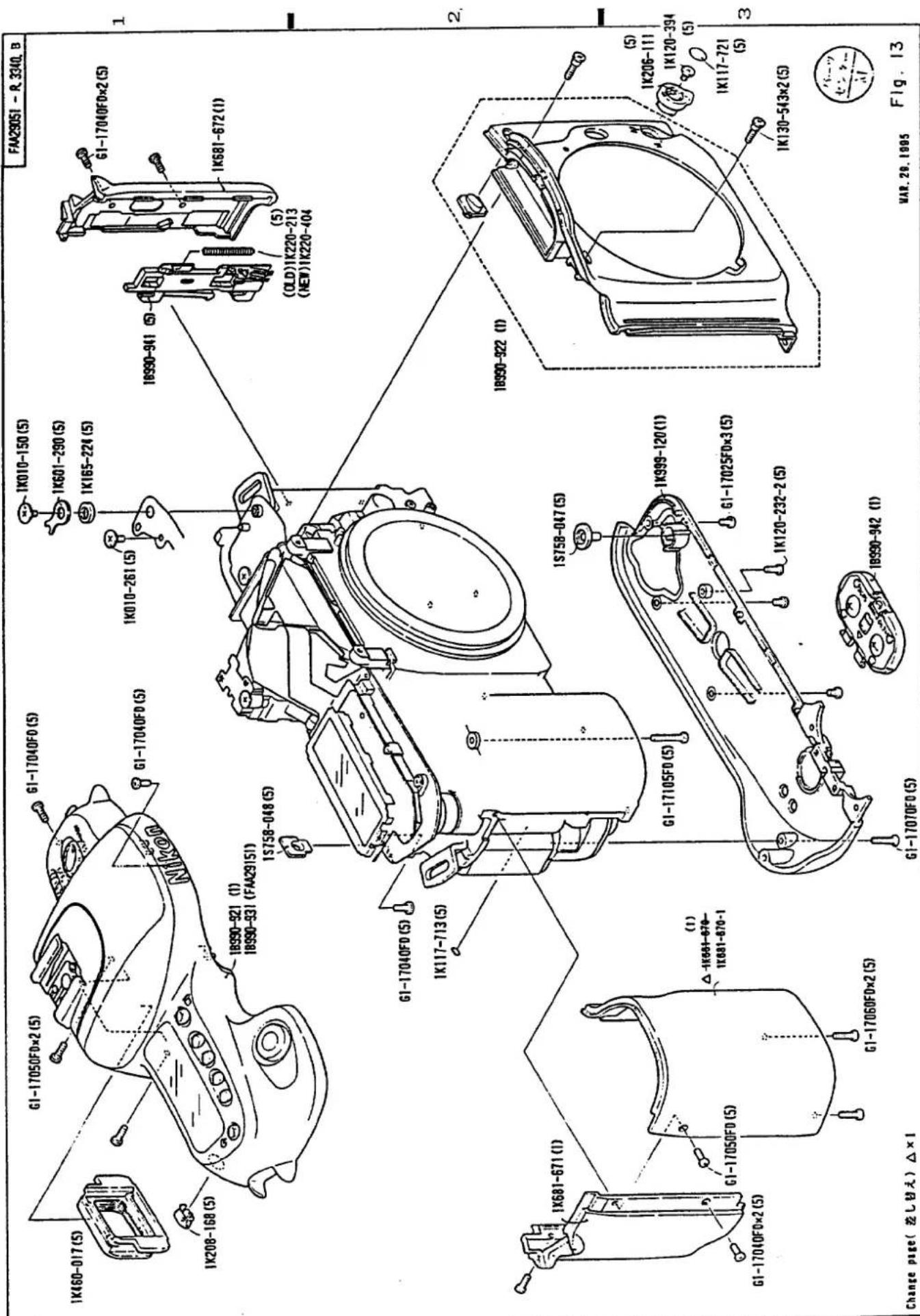
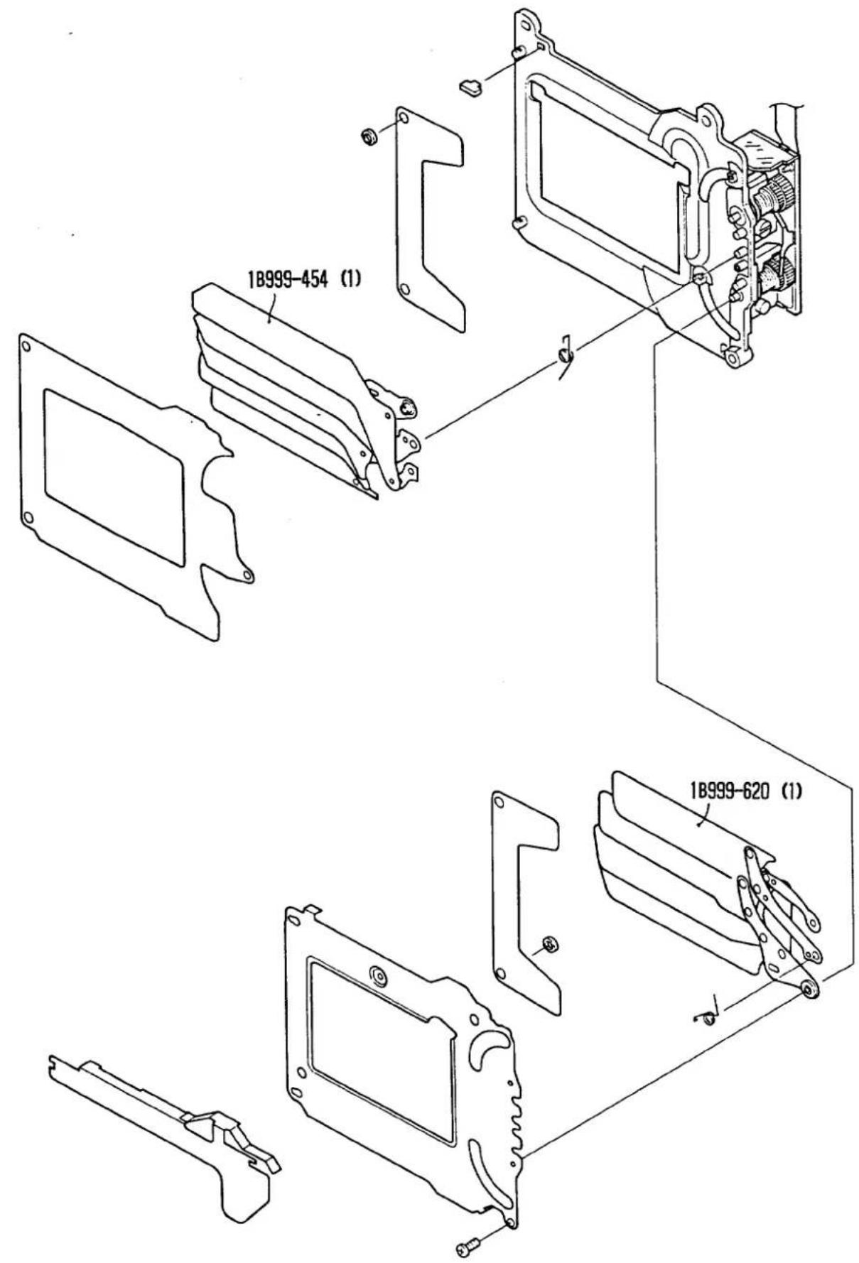
Fig. 14
部品表 Parts List
FAA29051-R. 3340.B
| 部品番号Part No. | 補助番号Ckt No. | 名称Name | 1台分個数Pcs.PerUnit | 部組品番号Assembly | 参照図書Fig.No | 販売区分Term ofDelivery | 備考Remarks | 要求单位Q'ty perorder |
| 1K001-083 | 514 | Screw | 2 | 1B990-988 | 4B1 | O△ | 5 | |
| 1K001-084 | 515 | Screw | 2 | 1B990-988 | 4A2 | O△ | 5 | |
| 1K001-085 | 516 | Screw | 2 | 1B990-988 | 6A3 | O△ | 5 | |
| 1K001-086 | 517 | Screw | 1 | 1B990-988 | 6B2 | O△ | 5 | |
| 1K001-087 | 518 | Screw | 3 | 1B990-988 | 6A2 | O△ | 5 | |
| 1K001-088 | 519 | Screw | 2 | 3A1 | O | 5 | ||
| *1K010-136 | 502 | Screw | 4 | 1B999-621-1 | 12B2 | O△ | 5 | |
| *1K010-138 | 500 | Screw | 4 | 1B999-621-1 | 12A2 | O△ | 5 | |
| *1K010-146 | 508 | Screw | 1 | 8B3 | O | 5 | ||
| *1K010-150 | 504 | Screw | 1 | 13C1 | O | 5 | ||
| *1K010-185 | 501 | Screw | 3 | 3A3 | O | 5 | ||
| 1K010-252-1(1K010-252) | 164 | AFセンサー 調整ビスAF Sensor adjusting screw | 3 | 7B3 | O | 5 | ||
| 1K010-253 | 339 | SBアップ制限ピンFlash up sttoper | 1 | 1B990-921 | 10B1 | O△ | 5 | |
| 1K010-254 | 498 | Screw | 1 | 2A2 | O | 5 | ||
| 1K010-255 | 499 | Screw | 1 | 2A3 | O | 5 | ||
部品表 Parts List
FAA29051-R3340.B
| 部品番号Part No. | 補助番号Ckt No. | 名称Name | 1台分個数Pcs.PerUnit | 部組品番号Assembly | 参照図香Fig.No | 販売区分Term ofDelivery | 備考Remarks | 要求单位Q'ty perorder |
| 1K010-256 | 503 | Screw | 4 | 1B990-988 | 5A3 | O△ | 5 | |
| 1K010-257 | 505 | Screw | 2 | 1B990-988 | 5B2 | O△ | 5 | |
| 1K010-258 | 506 | Screw | 1 | 3B2 | O | 5 | ||
| 1K010-260 | 509 | Screw | 1 | 1B990-921 | 10B1 | O△ | 5 | |
| 1K010-261 | 510 | Screw | 5 | 1B990-921 | 1-B29-B113-C1 | O△ | 5 | |
| 1K010-262 | 511 | Screw | 1 | 9B1 | O | 5 | ||
| 1K010-263 | 512 | Screw | 3 | 8B2 | O | 5 | ||
| 1K010-264 | 544 | Screw | 1 | 3A3 | O | 5 | ||
| 1K010-266 | 497 | Screw | 2 | 8A2 | O | 5 | ||
| *1K050-034 | 592 | Washer t=0.1 | 5 | 8 | O | RP-9452製技資料94F-1017参照方 | 5 | |
| *1K050-393 | 591 | Washer t=0.1 | 1 | 8B1 | O | RP-9452製技資料94F-1017参照方 | 5 | |
| *1K060-045 | 550 | E-リングE-Ring | 1 | 1B990-921 | 10A3 | O△ | 5 | |
| *1K060-047-1(1K060-047) | 552 | E-リングE-Ring | 1 | 1B990-988 | 4A3 | O△ | 5 | |
| *1K060-048 | 551 | E-リングE-Ring | 4 | 1B990-9881B990-991 | 4B2 | O△ | 5 | |
| 1K100-131 | 137 | 吊り金具(卷上げ側)Camera strap eyelet(film advance side) | 1 | 1A1 | O | 5 | ||
| 1K100-132 | 138 | 吊り金具(卷戻し側)Camera strap eyelet(film rewind side) | 1 | 1B1 | O | 5 | ||
| 1K110-423 | 117 | 巻き戻レベルtRewind belt | 1 | 3B3 | O | 5 | ||
部品表 Parts List
FAA29051-R3340.B
| 部品番号Part No. | 補助番号Ckt No. | 名称Name | 1台分個数Pcs.PerUnit | 部組品番号Assembly | 参照図番Fig.No | 販売区分Term ofDelivery | 備考Remarks | 要求単位Q'ty perorder |
| 1K115-660-1 | 436 | Tape | 1 | 1B990-988 | 6B1 | x | TA-0006 ( 6 X 13 ) | |
| *1K116-383 | 296 | ミラー受けモルトAMirrow holder sponge A | 1 | 1B990-988 | 4A1 | ○△ | 5 | |
| *1K116-437 | 297 | ミラー受けモルトBMirrow holder sponge B | 1 | 1B990-988 | 4A1 | ○△ | 5 | |
| *1K117-039 | 282 | 接眼視野枠Eyepiece mask | 1 | 1B990-9641B990-968 | 5A1 | ○△ | 5 | |
| *1K117-041 | 288 | ペンタ保護シートPentaprism protect sheet | 1 | 1B990-988 | 6B1 | ○△ | 5 | |
| *1K117-046-1(1K117-046) | 404 | パトローネ窓用スポンジSponge pad for patrone window | 1 | 1B999-621-1 | 12B2 | ○△ | 5 | |
| *1K117-287 | 187 | 防音ゴムRubber | 2 | 1B990-988 | 4B3 | ○△ | 5 | |
| 1K117-713 | 127 | フィルムマークFilm leader index mask | 1 | 13B2 | ○ | 5 | ||
| 1K117-714 | 134 | スプール室 穴煙しテープTape | 1 | 2A3 | ○ | 5 | ||
| 1K117-715 | 188 | 押さえゴムRubber | 2 | 1B990-988 | 4A2 | ○△ | 5 | |
| 1K117-716 | 228 | 植毛紙Flocked sheet | 1 | 1B990-988 | 5B3 | ○△ | 5 | |
| 1K117-717 | 285 | 視野枠Finder field frame | 1 | 1B990-988 | 6A1 | ○△ | RP-9453 | 5 |
| 1K117-822 | ||||||||
| 1K117-719 | 300A | 合致スペーサー t=0.2Spacer for focus screen | 0-1 | 1B990-988 | 6B2 | ○△ | 5 | |
| 1K117-720 | 300B | 合致スペーサー t=0.4Spacer for focus screen | 0-1 | 1B990-988 | 6B2 | ○△ | 5 | |
| 1K117-721 | 323 | A Fモード ノブカバーFocus mode selecter cover | 1 | 13D3 | ○ | 5 | ||
部品表 Parts List
FAA29051-R. 3340. B
| 部品番号Part No. | 補助番号Ckt No. | 名称Name | 1台分個数Pcs. PerUnit | 部組品番号Assembly | 参照図書Fig.No | 販売区分Term ofDelivery | 備考Remarks | 要求单位Q'ty perorder |
| 1K117-724 | 433 | 裏面SW両面テープTape. camera back switch | 1 | 1B1 | x | TA-0004(5X12) | ||
| 1K117-725 | 434 | Tape | 1 | 11A1 | O | RP-9451 | 5 | |
| 1K117-728 | 437 | Tape | 1 | 1A2 | x | TA-0004(8X8) | ||
| 1K117-741 | 438 | Tape | 1 | 7A1 | x | TA-0005(10 X 15) | ||
| 1K117-749 | 414 | ローラーゴムRoller rubber | 1 | 12B3 | O | 5 | ||
| 1K117-806 | 443 | Tape | 2 | 9-A210-B3 | x | TA-0005(13 X 6) | ||
| *1K120-015 | 527 | Screw | 2 | 1B990-988 | 5A3 | O△ | 5 | |
| *1K120-106 | 520 | Screw | 1 | 1B990-988 | 6A3 | O△ | 5 | |
| *1K120-232-2(1K120-232) | 454 | Screw | 1 | 13C3 | O | 5 | ||
| *1K120-307 | 523 | Screw | 4 | 1B990-921 | 10B3 | O△ | 5 | |
| *1K120-308 | 526 | Screw | 2 | 8A2B2 | O | 5 | ||
| 1K120-393 | 521 | Screw | 1 | 8A3 | O | 5 | ||
| 1K120-394 | 522 | Screw | 1 | 13D3 | O | 5 | ||
| 1K120-395 | 524 | Screw | 2 | 1B990-988 | 4B2 | O△ | 5 | |
| 1K120-396 | 525 | Screw | 1 | 7B1 | O | 5 | ||
| 1K123-157(1K123-046) | 530 | Screw | 4 | 1B990-988 | 6B3 | O△ | 5 | |
部品表 Parts List
FAA29051-R. 3340. B
| 部品番号Part No. | 補助番号Ckt No. | 名称Name | 1台分個数Pcs. Per Unit | 部組品番号Assembly | 参照図書Fig.No | 販売区分Term of Delivery | 備考Remarks | 要求単位Q'ty per order | |
| *1K117-820 | 447 | S Bコンデンサー用モルトSponge. SB condensor | 1 | 2A3 | ○ | RP-9451 | 5 | ||
| *1K117-828 | 448 | Tape | 1 | 9A2 | × | RP-9451TA-0010(5X7) | |||
| *1K117-829 | 449 | モルトブレンSponge | 1 | 9B2 | ○ | RP-9451 | 5 | ||
部品表 Parts List
FAA29051-R. 3340. B
| 部品番号Part No. | 補助番号Ckt No. | 名称Name | 1台分個数Pcs.PerUnit | 部組品番号Assembly | 参照図番Fig.No | 販売区分Term ofDelivery | 備考Remarks | 要求单位Q'ty perorder |
| *1K123-158 | 531 | Screw | 1 | 1B990-988 | 6B3 | ○△ | 5 | |
| 1K123-187 | 536 | Screw | 1 | 7A3 | ○△ | 5 | ||
| *1K130-481 | 542 | Screw | 2 | 1B990-988 | 4A3 | ○△ | 5 | |
| 1K130-540 | 540 | Screw | 2 | 1B990-988 | 6B3 | ○△ | 5 | |
| 1K130-541 | 541 | Screw | 1 | 1B990-988 | 6A2 | ○△ | 5 | |
| 1K130-542 | 543 | Screw | 2 | 7A2 | O | 5 | ||
| 1K130-543 | 545 | Screw | 2 | 13D3 | O | 5 | ||
| *1K146-082 | 548 | Screw | 1 | 1B990-988 | 4B2 | ○△ | 5 | |
| 1K165-224 | 442 | 圧接ゴム(バトローネ室上)Press-contact rubber(upper sideof film cartridge chamber) | 1 | 13C1 | O | 5 | ||
| 1K206-111 | 319 | A-M切り替えレバーFocus mode selector | 1 | 13D3 | O | 5 | ||
| 1K206-112 | 371 | 電源SWノブPower switch knob | 1 | 1B990-921 | 11B1 | ○△ | 5 | |
| 1K206-113 | 374 | モードセレクターExposure mode selector | 1 | 1B990-921 | 11B1 | ○△ | 5 | |
| 1K208-166 | 349 | レリーズ釦Release button | 1 | 1B990-921 | 11B2 | ○△ | 5 | |
| 1K208-167 | 354 | セレクト釦Select button | 4 | 1B990-921 | 11A1 | ○△ | 5 | |
| 1K208-168 | 355 | AE-L釦AE lock button | 1 | 13A1 | O | 5 | ||
部品表 Parts List
FAA29051-R. 3340. B
| 部品番号Part No. | 補助番号Ckt No. | 名称Name | 1台分個数Pcs.PerUnit | 部組品番号Assembly | 参照図番Fig.No | 販売区分Term ofDelivery | 備考Remarks | 要求单位Q'ty per order |
| 1K230-401 | 207 | ミラーダウンバネSpring.mirror-down | 1 | 1B990-988 | 5A3 | ○△ | 5 | |
| 1K230-402 | 218 | シャッター保止レバーバネSpring.shutter ratch lever | 1 | 1B990-988 | 5A3 | ○△ | 5 | |
| 1K230-403 | 223 | 保止解除レバーバネSpring.ratch release lever | 1 | 1B990-988 | 5A3 | ○△ | 5 | |
| 1K230-407 | 336 | SBアップバネFlash up spring | 1 | 1B990-921 | 10B1 | ○△ | 5 | |
| *1K233-050-2(1K233-050) | 287 | ペンタ押さえバネPentaprism retaining spring | 1 | 1B990-988 | 6B1 | ○△ | 5 | |
| *1K233-076 | 284 | スクリーンバネFocus screen spring | 1 | 1B990-9641B990-988 | 5B1 | ○△ | 5 | |
| 1K233-089 | 177 | AF PI 円盤止めバネAF PI disk retaining spring | 1 | 1B990-988 | 4B3 | ○△ | 5 | |
| *1K240-468-4(1K240-468-2) | 302 | バヨネットバネLens mounting flange spring | 1 | 1B990-988 | 6B3 | ○△ | 5 | |
| *1K240-747 | 405 | パトローネ押さえ板(裏蓋)Film cartridge retainer plate (camera back) | 1 | 1B999-621-1 | 12B4 | ○△ | 5 | |
| *1K240-867 | 343 | シューバネShoe spring | 1 | 10A2 | ○ | 5 | ||
| 1K240-932 | 370 | メインSWクリックバネClick spring for power switch | 1 | 1B990-921 | 11B2 | ○△ | 5 | |
| 1K240-933 | 373 | メインSWブラシPower switch brush | 1 | 1B990-921 | 11B3 | ○△ | 1 | |
| 1K240-935 | 377 | モードセレクター、クリックバネClick spring for exposure mode selector | 1 | 1B990-921 | 11B2 | ○△ | 5 | |
| 1K240-946 | 121 | パトローネ押さえ板(ボディ)Film cartridge retainer plate (body) | 1 | 1B1 | ○ | 5 | ||
部品表 Parts List
FAA29051-R. 3340. B
| 部品番号Part No. | 補助番号Ckt No. | 名称Name | 1台分個数Pcs. Per Unit | 部組品番号Assembly | 参照図香Fig.No | 販売区分Term of Delivery | 備考Remarks | 要求単位Q'ty per order |
| *1K260-371 | 183 | AFカップリングギ7-AF coupling gear | 1 | 1B990-988 | 4A3 | ○△ | 5 | |
| 1K260-684 | 47 | 減速ギ7-FReducing gear F | 1 | 3B2 | ○ | 5 | ||
| 1K260-685 | 48 | 減速ギ7-GReducing gear G | 1 | 3B2 | ○ | 5 | ||
| 1K260-687 | 50 | 巻上げアイドルギ7-NIdle gear N .fFilm advance idle gear N | 1 | 3B1 | ○ | 5 | ||
| 1K260-688 | 62 | 第2太陽ギ7-I2nd sun gear I | 1 | 3A3 | ○ | 5 | ||
| 1K260-690 | 64 | 第3太陽ギ7-J3rd sun gear J | 1 | 3A2 | ○ | 5 | ||
| 1K260-692 | 67 | 巻き戻しギ7-Film rewind gear | 1 | 3A2 | ○ | 5 | ||
| 1K260-693 | 104 | スプロケットギ7-Sproket gear | 1 | 2A1 | ○ | 5 | ||
| 1K275-085 | 68 | 巻き戻しベルトギ7-Film rewind belt gear | 1 | 3B3 | ○ | 5 | ||
| 1K275-086 | 103 | スプロケットSproket | 1 | 2A2 | ○ | 5 | ||
| 1K275-087 | 112 | 巻き戻しフォークギ7-Fork pully | 1 | 8B2 | ○ | 5 | ||
| 1K277-167 | 43 | 減速ギ7-BReducing gear B | 1 | 3A2 | ○ | 5 | ||
| 1K277-168 | 44 | 減速ギ7-CReducing gear C | 1 | 3A2 | ○ | 5 | ||
| 1K277-169 | 45 | 減速ギ7-DReducing gear D | 1 | 3A2 | ○ | 5 | ||
| 1K277-170 | 46 | 減速ギ7-EReducing gear E | 1 | 3A2 | ○ | 5 | ||
部品表 Parts List
FAA29051-R. 3340. B
| 部品番号Part No. | 補助番号Ckt No. | 名称Name | 1台分個数Pcs.PerUnit | 部組品番号Assembly | 参照図番Fig.No | 販売区分Term ofDelivery | 備考Remarks | 要求单位Q'ty perorder |
| 1K277-171 | 51 | 巻上げアイドルギ7-OFilm advance idle gear 0 | 1 | 3B1 | O | 5 | ||
| 1K277-172 | 57 | スプールSpool | 1 | 2B2 | O | 5 | ||
| 1K277-173 | 180 | AF 減速ギ7-BAF reducing gear B | 1 | 1B990-988 | 4B3 | O△ | 5 | |
| 1K277-174 | 161 | AF 減速ギ7-CAF reducing gear C | 1 | 1B990-988 | 4B3 | O△ | 5 | |
| 1K277-175 | 182 | AF 減速ギ7-DAF reducing gear D | 1 | 1B990-988 | 4B3 | O△ | 5 | |
| *1K300-076 | 320 | フォーカスモードカムFocus mode cam | 1 | 1B990-988 | 4B2 | O△ | 5 | |
| 1K300-097 | 66 | チャージカムCharge cam | 1 | 3B2 | O | 5 | ||
| *1K371-150-1(1K371-150) | 184 | AF カップリング軸AF coupling shaft | 1 | 1B990-988 | 4B3 | O△ | 5 | |
| 1K371-834 | 308 | レンズ着脱ピンLens release pin | 1 | 1B990-9911B990-988 | 4B2 | O△ | 5 | |
| 1K371-837 | 368 | ゴム蓋Rubber lid | 2 | 1B990-921 | 10A3 | O△ | 5 | |
| 1K371-838 | 407 | スプールローラー(裏蓋)Spool roller(camera back) | 1 | 1B999-621-1 | 12B3 | O△ | 5 | |
| *1K404-066 | 301 | バヨネットマウントLens mounting flange | 1 | 1B990-988 | 6B3 | O△ | 5 | |
| *1K406-032-1(1K406-032) | 341 | シュー一座Accessory shoe | 1 | 10A2 | O | 5 | ||
| *1K460-017 | 283 | 接眼枠Eyepiece faame | 1 | 13A1 | O | 5 | ||
RP-INF. NO. 9528
部品表 Parts List
FAA29051-R. 3340. B
| 部品番号Part No. | 補助番号Ckt No. | 名称Name | 1台分個数Pcs. Per Unit | 部組品番号Assembly | 参照図番Fig.No | 販売区分Term of Delivery | 備考Remarks | 要求单位Q'ty per order |
| *1K600-762 | 441 | 圧接ゴム(前ボディ)Press-contact rubber(Front body) | 1 | 7B2 | ○ | 5 | ||
| 1K601-288 | 359 | LCD窓LCD window | 1 | 11A1 | ○ | RP-9451 | 5 | |
| 1K601-290 | 440 | 圧接板(パトローネ室上)Press-contact plate(upper side of film cartridge chamber) | 1 | 13C1 | ○ | 5 | ||
| 1K601-292 | 439 | 圧接板(前ボディ)Press-contact plate.(front body) | 1 | 7B2 | ○ | 5 | ||
| *1K611-472 | 286 | ペンタ押さえ板pentaprism retaining plate | 1 | 1B990-988 | 6B1 | ○△ | 5 | |
| 1K611-942 | 171 | AFモーター基板AF motor base plate | 1 | 1B990-988 | 4B3 | ○△ | 1 | |
| 1K611-951 | 346 | シュー裏打ち板Shoe shield plate | 1 | 1B990-921 | 10B3 | ○△ | 5 | |
| 1K611-952 | 248 | 遮光板Light baffle plate | 1 | 7A2 | ○ | 5 | ||
| 1K611-954 | 295 | AE SPD シールド板AE SPD Shield plate | 1 | 1B990-9641B990-988 | 5B1 | ○△ | 5 | |
| *1K630-772 | 334 | SB 回転軸Slash head shaft | 1 | 1B990-921 | 10A1 | ○△ | 5 | |
| 1K630-857 | 114 | 巻き戻し フォークFilm rewind Fork | 1 | 8B1 | ○ | 5 | ||
| *1K640-636 | 185 | AFカップリングカラーAF Coupring coller | 1 | 1B990-988 | 4A3 | ○△ | 5 | |
| 1K681-6701K681-670-1 | 26 | グリップ前カバーHand glip front cover | 1 | 13B3 | ○ | RP-95189SF-2003RP-9528 | 1 | |
| 1K681-671 | 27 | グリップ後カバーHand glip rear cover | 1 | 13A2 | ○ | 1 | ||
| 1K681-672 | 28 | 裏査開閉レバーカバーCamera back lock release cover | 1 | 13D1 | ○ | 1 | ||
| 1K681-673 | 41 | 給送上基板Film advance upper base plate | 1 | 3B1 | ○ | 5 | ||
Change page(差し替え)△×1
-P10·F50-
Mar. 29. 1995
部品表 Parts List
FAA29051-R. 3340. B
| 部品番号Part No. | 補助番号Ckt No. | 名称Name | 1台分個数Pcs.PerUnit | 部組品番号Assembly | 参照図書Fig.No | 販売区分Term ofDelivery | 備考Remarks | 要求单位Q'ty perqorder |
| 1K681-674 | 61 | 給送下基板Film advance lower base plate | 1 | 3B3 | ○ | 5 | ||
| 1K681-676 | 101 | スプロケット ギ7 基板Sprocket gear base plate | 1 | 2B1 | ○ | 1 | ||
| 1K681-677 | 102 | スプロケット ギ7 カバーSprocket gear cover | 1 | 2B1 | ○ | 1 | ||
| 1K681-678 | 122 | パトローネ受けFilm cartridge set mold | 1 | 8A1 | ○ | 5 | ||
| 1K681-679 | 125 | DX接点カバーDX contact cover | 1 | 1A3 | ○ | 5 | ||
| 1K681-680 | 130 | スプールローラー基板Spool roller base plate | 1 | 2A2 | ○ | 1 | ||
| 1K681-684 | 172 | AFギ7 基板AF gear base plate | 1 | 1B990-988 | 4B3 | ○△ | 1 | |
| 1K681-685 | 178 | AF PI 円盤AF PI disk | 1 | 1B990-988 | 4B3 | ○△ | 5 | |
| 1K681-689 | 240 | TTL SPD 押さえブロックTTL SPD retaining brock | 1 | 1B990-988 | 5B3 | ○△ | 5 | |
| 1K681-690 | 241 | L基板L base plate | 1 | 1B990-988 | 5B3 | ○△ | 5 | |
| 1K681-693 | 331 | カバーFlash cover | 1 | 1B990-921 | 10B1 | ○△ | 1 | |
| 1K681-695 | 333 | プロテクターProtector | 1 | 1B990-921 | 10B2 | ○△ | 1 | |
| 1K681-697 | 372 | 電源SW裏打ち板Power switch plate | 1 | 1B990-921 | 11B2 | ○△ | 5 | |
| 1K681-699 | 391 | 外部LCD基板LCD pane base plate | 1 | 9A1 | ○ | RP-9453 | 5 | |
| *1K681-699-1 | ||||||||
| 1K681-700 | 392 | 圧接基板Press-contact base plate | 1 | 1B2 | ○ | 5 | ||
部品表 Parts List
FAA29051-R. 3340. B
| 部品番号Part No. | 補助番号Ckt No. | 名称Name | I台分個数Pcs.PerUnit | 部組品番号Assembly | 参照図書Fig.No | 販売区分Term ofDelivery | 備考Remarks | 要求単位Q'ty perorder |
| 1K999-118 | Xe管Xenon tube | 1 | 10B2 | ○ | 5 | |||
| 1K999-119 | トリガーコイルTrigger coil | 1 | 10A1 | ○ | 5 | |||
| 1K999-120 | 25 | 圧カバーBottom cover | 1 | 13C3 | ○ | No2001001~ | 1 | |
| *1G308-026 | G5 | 接眼レンズEyepiece lens | 1 | 1B990-9641B990-988 | 5A1 | ○△ | 1 | |
| *1G415-013 | G4 | ペンタブリズムPentaprism | 1 | 1B990-988 | 6A1 | ○△ | 1 | |
| 1G571-007 | G1 | 主ミラーMain mirror | 1 | 1B990-9881B990-981 | 5A2 | ○△ | 1 | |
| 1G680-034 | G11 | IRフィルター(TTL用)IR filter(TTL) | 1 | 1B990-988 | 5B3 | ○△ | 1 | |
| 1G950-078 | G3 | スクリーンFocus Screen | 1 | 1B990-988 | 6B2 | ○△ | RP-9608 | 1 |
Change Page 差替え (△×1)
部品表 Parts List
FAA29051-R. 3340.B
| 部品番号Part No. | 補助番号Ckt No. | 名称Name | 1台分個数Pcs.PerUnit | 部組品番号Assembly | 参照図番Fig.No. | 販売区分Term ofDelivery | 備考Remarks | 要求单位Q'ty perorder |
| 1S223-008 | 1046 | モータドライバICMD IC | 1 | 1S020-112 | 1B3 | ○△ | 5 | |
| 1S237-076 | 1045 | 6分断測光IC6 split metering IC | 1 | 1B990-975 | 9B1 | ○△ | 5 | |
| 1S258-016 | 1026 | AFフォトインタラブタAF photo interrupter | 1 | 1B990-9881B990-982 | 4B3 | ○△ | 5 | |
| *1S260-055 | 1025 | LED(セルフ表示用)LED(for self indicator) | 1 | 1S020-112 | 1B3 | ○△ | 5 | |
| 1S622-004 | 34 | レリーズMgRelease Mg | 1 | 1B990-988 | 5A2 | ○△ | 5 | |
| 1S700-368 | 107 | スプロケットPCBSproket PCB | 1 | 2B1 | ○ | 1 | ||
| 1S705-250 | 1010 | AE-L FPCAE-L FPC | 1 | 9A2 | ○ | 5 | ||
| 1S705-255-2 | 1005 | ホットシューFPCHot shoe FPC | 1 | 1B990-921 | 10B3 | ○△ | 5 | |
| 1S705-259 | 1009 | AF FPCAF FPC | 1 | 1B990-988 | 4B3 | ○△ | 5 | |
| 1S758-046 | 353 | LCD押し釦ゴムLCD set button rubber | 1 | 1B990-921 | 11A3 | ○△ | 5 | |
| 1S758-047 | 387 | 巻戻釦ゴムRewind button rubber | 1 | 13C2 | ○ | 5 | ||
| 1S758-048 | 357 | AE-LゴムAE-L rubber | 1 | 13B1 | ○ | 5 | ||
| 1S726-074 | 446 | アセテートクロステープTape | 1 | 10A2 | x | TA-0006S (6 X 20) | ||
| 1S999-115 | スライダーSlider | 1 | 7B1 | ○ | RP-9479(サービス 技報94-39参照方) | 5 | ||
| 1S999-116 | スライダーSlider | 1 | 7B1 | ○ | RP-9479(サービス 技報94-39参照方) | 5 | ||
| 1S999-117 | スライダーSlider | -1 | 7B1 | ○ | RP-9479(サービス 技報94-39参照方) | 5 | ||
Change page(差し替え) × 3
RP-INF. NO. 9479
-P13·F50-
DEC. 9.1994
部品表 Parts List
FAA29051-R. 3340. B
| 部品番号Part No. | 補助番号Ckt No. | 名称Name | 1台分個数Pcs.PerUnit | 部組品番号Assembly | 参照図番Fig.No. | 販売区分Term ofDelivery | 備考Remarks | 要求单位Q'ty perorder |
| A1-17025FA | 453 | Screw | 1 | 1B990-975 | 6B3 | O△ | 5 | |
| B1-14020FA | 465 | Screw | 3 | 1B990-988 | 4-B38-B3 | O△ | 5 | |
| G1-14025FD | 470 | Screw | 1 | 1B990-988 | 5B1 | O△ | 5 | |
| G1-14030FA | 471 | Screw | 1 | 7B1 | O | 5 | ||
| G1-17020FA | 472 | Screw | 2 | 1B999-621-1 | 12B2 | O△ | 5 | |
| G1-17025FD | 473 | Screw | 7 | 1B990-9211B990-988 | 1-B38-A110-B3 | O△ | 5 | |
| G1-17030FD | 474 | Screw | 6 | 1B990-988 | 1-A110-B211-B2 | O△ | 5 | |
| G1-17035FD | 481 | Screw | 6 | 1B990-9211B990-988 | 1-B35-B310-A2 | O△ | 5 | |
| G1-17040FD | 475 | Screw | 14 | 8-A313-A3B1.B2 | O | 5 | ||
| G1-17050FD | 477 | Screw | 5 | 9-A113-A113-A3 | O | 5 | ||
| G1-17060FD | 476 | Screw | 2 | 13A3 | O | 5 | ||
| G1-17070FD | 482 | Screw | 1 | 13B3 | O | 5 | ||
| G1-17105FD | 478 | Screw | 1 | 13B3 | O | 5 | ||
| G2-17040FA | 479 | Screw | 2 | 1B990-988 | 4A3 | O△ | 5 | |
| H1-17040FD | 490 | Screw | 4 | 2-B17-A2 | O | 5 | ||
部品表 Parts List
FAA29051-R.3340.B
| 部品番号Part No. | 補助番号Ckt No. | 名称Name | 1台分個數Pcs.PerUnit | 部組品番号Assembly | 參照図番Fig.No. | 販売区分Term ofDelivery | 備考Remarks | 要求单位Q'ty per order | |
| H1-17075FA | 491 | Screw | 1 | 1A1 | ○ | 5 | |||
| H1-20040FD | 493 | Screw | 4 | 1A1B1 | ○ | 5 | |||
| H1-20050FD | 492 | Screw | 4 | 8A3B3 | ○ | 5 | |||
| H1-20055FA | 495 | Screw | 1 | 8A2 | ○ | 5 | |||
| H1-20080FA | 494 | Screw | 2 | 8A1 | ○ | 5 | |||
| S1-00800SX | 560 | E-ring | 6 | 1B990-988 | 11A3 | ○△ | 5 | ||
| S1-01200SX | 561 | E-ring | 1 | 3A3 | ○ | 5 | |||
| S1-01500SX | 562 | E-ring | 1 | 1B990-921 | 11A3 | ○△ | 5 | ||
部組品表 Assembly List
FAA29051-R. 3340. B
| 部組番号Part No. | 補助番号Ckt No. | 名称Name | 1台分個数Pcs.PerUnit | 大部組品番号Main assembly No. | 参照図香Fig.No | 備考Remarks | 要求单位Q'ty per order |
| *1B001-712 | B312 | F min SWF min SW | 1 | 1B990-988 | 6A3 | 1 | |
| 1B060-559 | B31 | シャッター組Shutter unit | 1 | 1B999-4541B999-620 | 7A3 | 1 | |
| 1B060-560 | B32 | 巻上げモーターFilm advance motor | 1 | 3A1 | 1 | ||
| 1B240-112 | B123 | DX接点 組DX contact unit | 1 | 1B2 | 5 | ||
| 1B240-113 | B335 | SBポップアップSWFlash pop-up SW | 1 | 1B990-921 | 10B3 | 5 | |
| *1B610-035-2(1B610-035-1) | B303 | レンズ接点 組Lens contact unit | 1 | 1B990-988 | 4B2 | 5 | |
| *1B990-800 | B342 | シュー座Shoe base unit | 1 | 1B990-921 | 10A2 | 5 | |
| 1B990-921 | B23 | 上カバー(F50)Top cover (F50) | 1 | 11-A113-B1 | 1 | ||
| 1B990-922 | B24 | 前カバーFront cover | 1 | 13C2 | 1 | ||
| 1B990-923 | B33 | AFモーターAF motor | 1 | 1B990-988 | 4A2 | 1 | |
| 1B990-925 | B53 | 第1太陽ギア アーム組Planet gear unit | 1 | 3B2 | 1 | ||
| 1B990-929 | B79 | ギ7 組Coupling gear unit | 1 | 3A2 | 1 | ||
| 1B990-931(FAA29151) | 上カバー(N50)Top cover (N50) | 1 | 11-A113-B1 | For USA | 1 | ||
| 1B990-9321B990-932-1 | B92 | チャージレバー組Charge lever unit | 1 | 3B2 | 製技資95F-1016製技補説95-17RP-9563 | 1 | |
Change page (差し替え) △×2
JUL. 24. 1995
部組品表 Assembly List
FAA29251-R.3340.B
| 部組番号Part No. | 補助番号Ckt No. | 名称Name | 1台分個数Pcs. Per Unit | 大部組品番号Main assembly No. | 参照図書Fig.No | 備考Remarks | 要求単位Q'ty per order |
| 1B990-985 | B6411 | 圧板Pressure plate | 1 | 15B3 | 1 | ||
| *1B999-569 | 421 | DB モジュールDB module | 1 | 15B2 | 1 | ||
| 1B999-622 | 裏重組Camera back unit | 1 | 15B1 | 1 | |||
| 1B999-824 | 中重組Inner cover assembly | 1 | 15A3 | RP-9609 | 1 | ||
| 1S020-101 | B7101 | DB FPCDB FPC | 1 | 15B3 | 1 | ||
部品表 Parts List
FAA29051-R.3340.B
| 部品番号Part No. | 補助番号Ckt No. | 名称Name | 1台分個数Pcs. Per Unit | 部組品番号Assembly | 参照図書Fig.No. | 販売区分Term of Delivery | 備考Remarks | 要求単位Q'ty per order |
| 1K208-169 | 356 | SELF知、メニュー知Self and menu button | 2 | 1B990-921 | 11Al.2 | ○△ | 5 | |
| 1K208-170 | 362 | ロック解除釦Flash lock-release button | 1 | 1B990-921 | 10B2 | ○△ | 5 | |
| *1K220-041-1(1K220-041) | 310 | レンズ着脱ビンバネLens release pin spring | 1 | 1B990-9911B990-988 | 4B2 | ○△ | 5 | |
| *1K220-213 | 142 | 裏重開閉レバーバネCamera back lock-release spring | 1 | 13D2 | ○ | RP-9479 RP-9452 | 5 | |
| *1K220-404 | ||||||||
| *1K220-217 | 163 | AFセンサーAF adjustment spring | 3 | 7B3 | ○ | 5 | ||
| 1K220-385 | 115 | 巻き戻しフォークバネSpring, film rewind fork | 1 | 8B2 | ○ | 5 | ||
| 1K220-387 | 210 | レリーズMgSpring, release Mg | 1 | 1B990-988 | 5A2 | ○△ | 5 | |
| 1K220-388 | 309 | レンズ着脱卸バネLens release button spring | 1 | 1B990-988 | 4B1 | ○△ | 5 | |
| 1K220-389 | 363 | S Bロック解除釦バネSpring, flash lock-release button | 1 | 1B990-921 | 10B2 | ○△ | 5 | |
| *1K225-157 | 316 | F min SWバネSpring, F min SW | 1 | 1B990-988 | 6B3 | ○△ | 5 |
部組品表 Assembly List
FAA29051-R. 3340.B
| 部組番号Part No. | 補助番号Ckt No. | 名称Name | 1台分個数Pcs. Per Unit | 大部組品番号Main assembly No. | 参照図番Fig.No | 備考Remarks | 要求单位Q'ty per order |
| 1B990-935 | B105 | 給送検出ギ7組Detection gear unit | 1 | 2B1 | 5 | ||
| 1B990-936 | B111 | 巻戻し基板Film rewind fork base plate unit | 1 | 8B2 | 5 | ||
| 1B990-938 | B129 | スプールローラー組Spool roller unit | 1 | 2A3 | 5 | ||
| 1B990-940 | B131 | 三脚基板Tripod base plate | 1 | 8B2 | 5 | ||
| 1B990-941 | B141 | 裏査開閉レバーCamera back lock release lever | 1 | 13D1 | 5 | ||
| 1B990-942 | B151 | 電池査査Battery chamber lid | 1 | 13C3 | 1 | ||
| 1B990-943 | B156 | 電池接点組Battery contact unit | 1 | 1A1 | 5 | ||
| 1B990-944 | B161 | AFセンサー組AF Sensor unit | 1 | 7B3 | 1 | ||
| 1B990-947 | B191 | レンズ着脱釦基板Lens release button base plate | 1 | 1B990-797 | 4B1 | 1 | |
| 1B990-948 | B193 | AF 横レバー組AF transverse lever unit | 1 | 1B990-797 | 4A2 | 1 | |
| 1B990-949 | B2201 | I基板組I base plate unit | 1 | 1B990-988 | 5A3 | 1 | |
| 1B990-954 | B250 | ラグ板Lag plate | 1 | 8B3 | 5 | ||
| 1B990-959 | B242 | Lミラー軸組L mirror shaft unit | 1 | 1B990-797 | 5B1 | 5 | |
| 1B990-964 | B281 | プリズムボックス組Prism box unit | 1 | 1B990-988 | 5A1 | 1 | |
| 1B990-967 | B315 | Fmin プリント板Fmin PCB | 1 | 1B990-988 | 6A3 | 1 | |
部組品表 Assembly List
FAA29051-R. 3340.B
| 部組番号Part No. | 補助番号Ckt No. | 名称Name | 1台分個数Pcs.PerUnit | 大部組品番号Main assembly No. | 参照図番Fig.No | 備考Remarks | 要求単位Q'ty per order |
| 1B990-968 | B325 | A-M SWA-M SW | 1 | 1B990-988 | 6B2 | 5 | |
| 1B990-971 | B375 | モードSWExposure mode SW | 1. | 1B990-921 | 11B2 | 5 | |
| 1B990-973 | B411 | 圧板Pressure plate | 1 | 12A3 | 1 | ||
| TB990-974 | B417 | ローラー基板(裏畫)Roller base plate (camera back) | 1 | 1B999-621-1 | 12A2 | RP-9609 | 1 |
| 1B990-974-1 | B417 | ローラー基板(裏畫)Roller base plate (camera back) | 1 | 1B999-621-1 | 12A2 | RP-9609 | 1 |
| 1B990-975 | B2002 | ペンタFPCPenta FPC | 1 | 9B1 | 1 | ||
| 1B990-976 | B2006 | 内LCD FPCViewfinder LCD FPC | 1 | 7A1 | 1 | ||
| 1B990-981 | B2231 | ミラー組Mirror unit | 1 | 1B990-988 | 5B2 | 1 | |
| 1B990-982 | B2251 | 絞り制御基板Diaphragm control unit | -1 | 1B990-988 | 6A2 | 1 | |
| 1B990-983 | B2382 | レリーズSW組Rerease SW unit | 1 | 1A1 | 1 | ||
| 1B990-988 | B2022 | 前ボディ組Front body unit | 1 | 456 | 1 | ||
| 1B990-991 | B306 | レンズ着脱卸組Lens release button unit | 1 | 1B990-988 | 4B1 | 1 | |
| *1B999-454 | シャッター先幕組Opening curtain | 1 | 14A1 | 1 | |||
| 1B999-620 | シャッター後幕組Closing curtain | 1 | 14B2 | 1 | |||
| 1B999-621-1 | 裏畫組Camera back unit | 1 | 12A1 | 1 | |||
Change Page 差替え ( × 2 )
APR. 10.1996
部組品表 Assembly List
FAA29051-R. 3340. B
| 部組番号Part No. | 補助番号Ckt No. | 名称Name | 1台分個数Pcs.PerUnit | 大部組品番号Main assembly No. | 参照図番Fig.No | 備考Remarks | 要求单位Q'ty per order |
| *1B001-712 | B312 | F min SWF min SW | 1 | 1B990-988 | 6A3 | 1 | |
| 1B060-559 | B31 | シャッター組Shutter unit | 1 | 1B999-4541B999-620 | 7A3 | 1 | |
| 1B060-560 | B32 | 巻上げモーターFilm advance motor | 1 | 3A1 | 1 | ||
| 1B240-112 | B123 | DX接点 組DX contact unit | 1 | 1B2 | 5 | ||
| 1B240-113 | B335 | SBポップアップSWFlash pop-up SW | 1 | 1B990-921 | 10B3 | 5 | |
| *1B610-035-2(1B610-035-1) | B303 | レンズ接点 組Lens contact unit | 1 | 1B990-988 | 4B2 | 5 | |
| *1B990-800 | B342 | シュー座Shoe base unit | 1 | 1B990-921 | 10A2 | 5 | |
| 1B990-921 | B23 | 上カバー(F50)Top cover (F50) | 1 | 11-A113-B1 | 1 | ||
| 1B990-922 | B24 | 前カバーFront cover | 1 | 13C2 | 1 | ||
| 1B990-923 | B33 | AFモーターAF motor | 1 | 1B990-988 | 4A2 | 1 | |
| 1B990-925 | B53 | 第1太陽ギ7 アーム組Planet gear unit | 1 | 3B2 | 1 | ||
| 1B990-929 | B79 | ギ7 組Coupling gear unit | 1 | 3A2 | 1 | ||
| 1B990-931(FAA29151) | 上カバー(N50)Top cover (N50) | 1 | 11-A113-B1 | For USA | 1 | ||
| 1B990-9321B990-932-1 | B92 | チャージレバー組Charge lever unit | 1 | 3B2 | 製技資95F-1016製技補説95-17RP-9563 | 1 | |
Change page (差し替え) △×2
-P16·F50-
JUL. 24. 1995
| ISO20-106 | B1022 | 外LCD组LCD panel unit | 1 | 9Al | 5 |
| 作成承認印 | 配布許可印 |
 |  |
F50D FAA29251
F50DP FAA29351
DB PARTS LIST
Exploded Drawings B1
Parts List B2
Assembly List B5
Nikon
NIKON CORPORATION
Tokyo, Japan
© Copyright 1994
ALL RIGHTS RESERVED
無断転載を禁ず!!
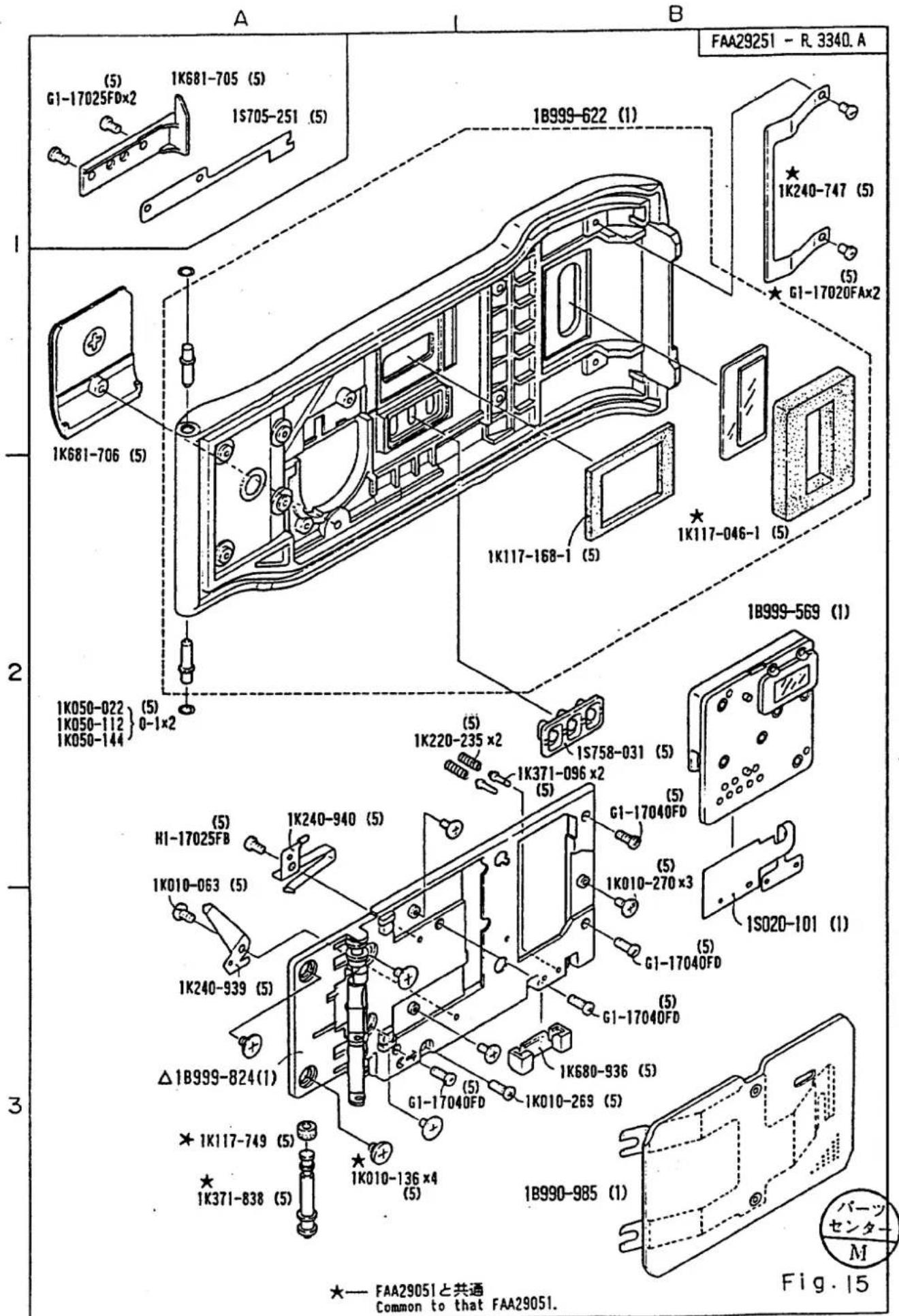
部品表 Parts List
FAA29251-R. 3340.A
| 部品番号Part No. | 補助番号Ckt No. | 名称Name | 1台分個数Pcs. Per Unit | 部組品番号Assembly | 参照図番Fig.No. | 販売区分Term of Delivery | 備考Remarks | 要求単位Q'ty per order |
| *1K010-063 | 533 | Screw | 1 | 15A2 | ○ | 5 | ||
| *1K010-136 | 502 | Screw | 4 | 15A3 | ○ | FAA29051 | 5 | |
| 1K010-269 | 496 | 裏蓋止めビスScrew, Camera back | 1 | 15B3 | ○ | 5 | ||
| 1K010-270 | 513 | Screw | 3 | 15B3 | ○ | 5 | ||
| *1K050-022 | 244 | Washer T=0.2 | 0-1 | 15A1A2 | ○ | 5 | ||
| *1K050-112 | Washer T=0.3 | ○ | 5 | |||||
| *1K050-144 | Washer T=0.1 | ○ | 5 | |||||
| *1K117-046-1(1K117-046) | 404 | パトローネ窓用スポンジSponge pad for patrone window | 1 | 1B999-622 | 15B2 | ○△ | FAA29051 | 5 |
| *1K117-168-1(1K117-168) | 422 | D B表示窓Sponge pad for DB display window | 1 | 1B999-622 | 15B2 | ○△ | 5 | |
| 1K117-749 | 414 | スプールローラーゴムSpool roller rubber | 1 | 15A3 | ○ | FAA29051 | 5 | |
| *1K220-235 | 428 | 接点ピンバネContact spring | 2 | 15A2 | ○ | 5 | ||
| 1K230-408 | 410 | スプールローラーバネSpool roller spring | 1 | 15A3 | ○ | 5 | ||
| *1K240-747 | 405 | パトローネ押さえバネRetaining spring for parrone | 1 | 15B1 | ○ | FAA29051 | 5 | |
| 1K240-939 | 423 | 一側電池接点Battery contact (negative) | 1 | 15A3 | ○ | 5 | ||
| 1K240-940 | 424 | +側電池接点Battery contact (positive) | 1 | 15A2 | ○ | 5 | ||
部品表 Parts List
FAA29251-R. 3340.A
| 部品番号Part No. | 補助番号Ckt No. | 名称Name | 1台分個数Pcs. Per Unit | 部組品番号Assembly | 参照図番Fig.No. | 販売区分Term of Delivery | 備考Remarks | 要求单位Q'ty per order |
| 1K360-064 | 409 | スプールローラー軸Spool roller shaft | 1 | 15A3 | ○ | 5 | ||
| *1K371-096 | 427 | 接点ピンContact pin | 2 | 15B2 | ○ | 5 | ||
| *1K371-838 | 407 | スプールローラーSpool roller | 1 | 15A3 | ○ | FAA29051 | 5 | |
| 1K630-861 | 406 | スプロケットローラーSprocket roller | 2 | 15A3 | ○ | 5 | ||
| *1K680-936 | 429 | 接点ブロックContact brock | 1 | 15B3 | ○ | 5 | ||
| 1K681-703 | 408 | スプールローラー 押さえ板Spool roller retaining plate | 1 | 15A3 | ○ | 5 | ||
| 1K681-705 | 122 | パトローネ受けFilm cartridge set mold | 1 | 15A1 | ○ | 5 | ||
| 1K681-706 | 419 | 電池蓋Battery lid | 1 | 15A1 | ○ | 5 | ||
| 1K681-707-1(1K681-707) | 420 | 中蓋Inner cover | 1 | 15A3 | ○ | 5 | ||
| 1S705-251 | 1012 | 接点 FPCDB contact FPC | 1 | 15A1 | ○ | 5 | ||
| *1S758-031 | 426 | 押し卸導電ゴムPush button rubber | 1 | 15B2 | ○ | 5 | ||
| 1S811-700 | 7116 | Wire (Brack) | 1 | × | W-0080BK | |||
| 1S811-769 | 7115 | Wire (Red) | 1 | × | W-0080RE | |||
部品表 Parts List
FAA29251-R. 3340.A
| 部品番号Part No. | 補助番号Ckt No. | 名称Name | 1台分個数Pcs.PerUnit | 部組品番号Assembly | 參照図番Fig.No. | 販売区分Term ofDelivery | 備考Remarks | 要求单位Q'ty perorder | |
| G1-17020FA | 472 | Screw | 2 | 15B1 | ○ | 5 | |||
| G1-17040FD | 475 | Screw | 4 | 15A3B2 | ○ | 5 | |||
| H1-17025FB | 534 | Screw | 1 | 15A2 | ○ | 5 | |||
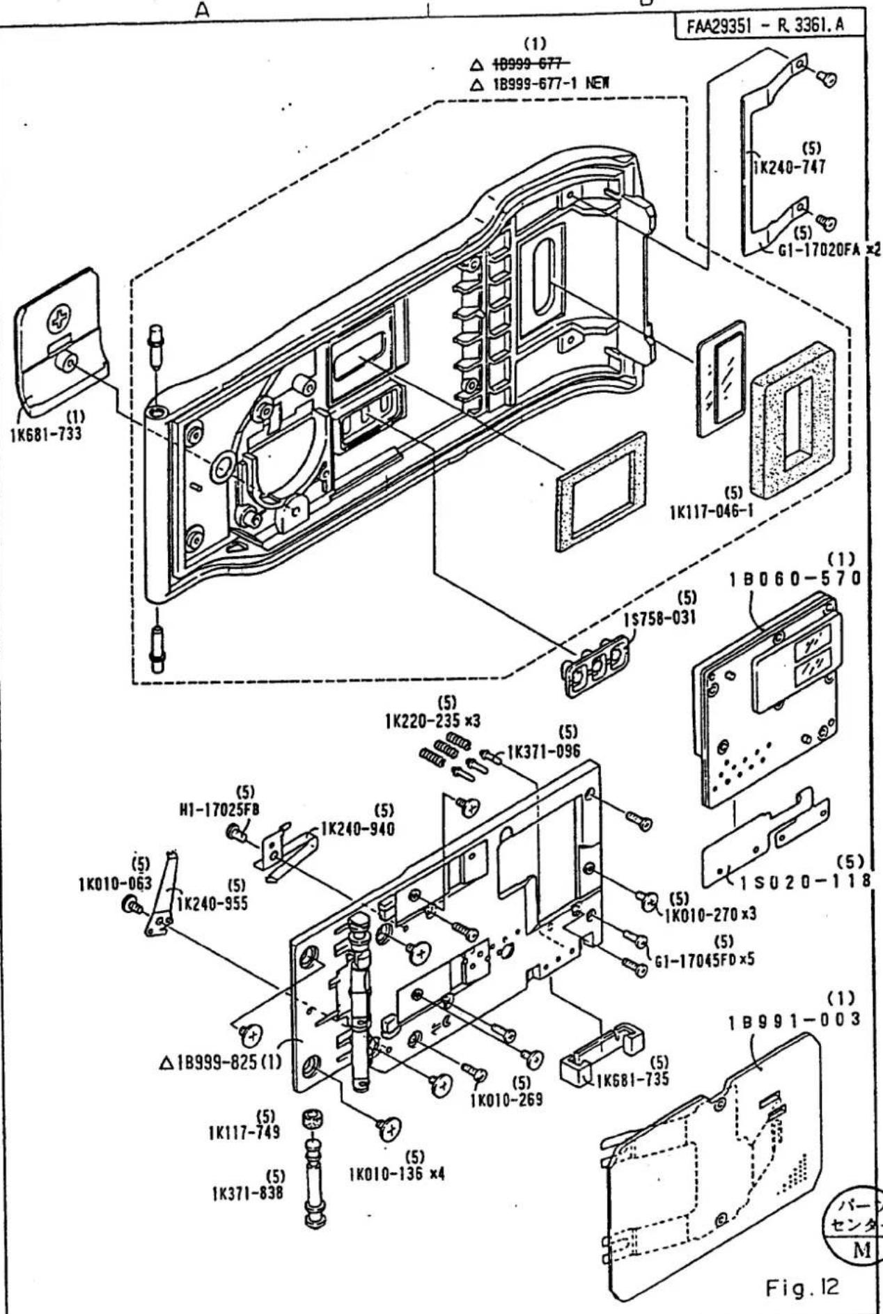
Mar. 25. 1996
部組品表 Assembly List
FAA29351-R. 3361. B
| 部組番号Part No. | 補助番号Ckt No. | 名称Name | 1台分個数Pcs. Per Unit | 大部組品番号Main assembly No. | 參照図書Fig.No. | 備考Remarks | 要求单位Q'ty per order |
| *1B990-971 | B375 | モードSWExposure mode SW | 1 | 1B990-921 | 11B2 | F50 | 5 |
| *1B990-975 | B2002 | ペンタFPCPenta FPC | 1 | 9B1 | F50 | 1 | |
| *1B990-981 | B2231 | ミラー組Mirror unit | 1 | 5B2 | F50 | 1 | |
| *1B990-982 | B2251 | 紋り制御基板Diaphragm control unit | 1 | 6A2 | F50 | 1 | |
| *1B990-983 | B2382 | レリーズSW組Rerease SW unit | 1 | 1A1 | F50 | 1 | |
| *1B990-991 | B306 | レンズ着脱扣組Lens release button unit | 1 | 4B1 | F50 | 1 | |
| 1B990-994 | B131 | 三脚基板Tripod base plate | 1 | 8B2 | 1 | ||
| 1B990-996 | B394 | パノラマSW基板Panorama SW base plate | 1 | 8A2 | 1 | ||
| 1B990-997 | B2006 | 内LCD-FPC部組Inner LCD-FPC unit | 1 | 7B1 | 1 | ||
| 1B991-002 | B2022 | 前板部組Front cover unit | 1 | 4.56.7 | 1 | ||
| 1B991-003 | B6412 | 圧板Prasure plate | 1 | 12B3 | 1 | ||
| 1B999-677 | DB裏査Camera back DB | 1 | 12B1 | RP-9667 | 1 | ||
| 1B999-677-1 | |||||||
| 1B999-825 | 中査組Innar cover assembly | 1 | 12A3 | RP-9609 | 1 | ||
Change Page 差替え (△×1)
-P19·F50D panorama -
APR. 10.1996
△