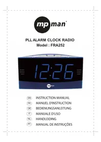
FRA 200 - Radio-réveil MPMAN - Notice d'utilisation et mode d'emploi gratuit
Retrouvez gratuitement la notice de l'appareil FRA 200 MPMAN au format PDF.


| Type d'appareil | Radio réveil |
| Fonction radio | AM/FM |
| Type d'alarme | Double alarme |
| Affichage | Écran digital |
| Alimentation | Non précisé |
| Fonction snooze | Oui |
| Réglage de la luminosité | Non précisé |
| Type d'horloge | Numérique |
| Fonction répétition | Oui |
| Alarme sonore | Radio ou buzzer |
| Dimensions | Non précisé |
| Poids | Non précisé |
| Matériau | Non précisé |
| Fonction batterie de secours | Non précisé |
| Connectivité | Non précisé |
| Couleur | Non précisé |
FOIRE AUX QUESTIONS - FRA 200 MPMAN
Questions des utilisateurs sur FRA 200 MPMAN
0 question sur cet appareil. Repondez a celles que vous connaissez ou posez la votre.
Poser une nouvelle question sur cet appareil
Téléchargez la notice de votre Radio-réveil au format PDF gratuitement ! Retrouvez votre notice FRA 200 - MPMAN et reprennez votre appareil électronique en main. Sur cette page sont publiés tous les documents nécessaires à l'utilisation de votre appareil FRA 200 de la marque MPMAN.
MODE D'EMPLOI FRA 200 MPMAN
This marking shown on the producer's literature, indicates that it should not be disposed with other household wastes at the end of its working life. To prevent possible harm to the environment or human health from uncontrolled waste disposal, please separate this from other types of wastes and recycle it responsibly to promote the sustainable reuse of material resources.
Household Users should contact either the retailer where they purchased this product, or their local government office, for details of where and how they can take this item for environmentally safe recycling.
Business users should contact their supplier and check the terms and conditions of the purchase contract.
This product should not be mixed with other commercial wastes for disposal.
INSTRUCTION MANUAL
MW/FM DUAL ALARM CLOCK RADIO

CAUTION
RISK OF ELECTRIC SHOCK
DO NOT OPEN

CAUTION: TO REDUCE THE RISK OF ELECTRIC SHOCK, DO NOT REMOVE COVER(OR BACK). NO USER-SERVICEABLE PARTS INSIDE. REFER SERVICING TO QUALIFIED SERVICE PERSONNEL.
WARNING: TO REDUCE THE RISK OF FIRE OR ELECTRIC SHOCK, DO NOT EXPOSE THIS APPLIANCE TO RAIN OR MOISTURE.

The lightning flash with arrowhead symbol, within an equilateral triangle is intended to alert the user to the presence of uninsulated 'dangerous voltage' within the product's enclosure that may be of sufficient magnitude to constitute a risk of electric shock to persons.

The exclamation point within an equilateral triangle is intended to alert the user to the presence of important operating and maintenance (servicing) instructions in the literature accompanying the appliance.
The symbols above are located at the bottom of the cabinet.
CAUTION: TO PREVENT FIRE OR SHOCK HAZARD, DO NOT USE THIS PLUG WITH AN EXTENSION CORD, RECEPTACLE OR OTHER OUTLET UNLESS THE BLADES CAN BE FULLY INSERTED TO PREVENT BLADE EXPOSURE.
Note: The manufacturer is not responsible for any radio or TV interference cause by unauthorized modifications to this equipment. Such modification could void the user's authority to operate the equipment.
A Consumer Guide to Product Safety
IMPORTANT SAFETY INSTRUCTIONS
1.) Read these instructions.
2.) Keep these instructions.
3.) Heed all warnings.
4.) Follow all instructions.
5.) Do not use this apparatus near water.
6.) Clean only with dry cloth.
7.) Do not block any ventilation openings. Install in accordance with the manufacturer's instructions.
8.) Do not install near any heat sources such as radiators, heat registers, stoves, or other apparatus (including amplifiers) that produce heat.
9.) Protect the power cord from being walked on or pinched particularly at plugs, convenience receptacles, and the point where they exit from the apparatus.
10.) Only use attachments / accessories specified by the manufacturer.
11.) Unplug this apparatus during lightning storms or when unused for long periods of time.
12.) Refer all servicing to qualified service personnel. Servicing is required when the apparatus has been damaged in any way, such as power-supply cord or plug is damaged, liquid has been spilled or objects have fallen into the apparatus, the apparatus has been exposed to rain or moisture, does not operate normally, or has been dropped.
13) Do not overload wall outlet. Use only power source as indicated.
14.) Use replacement parts as specified by the manufacturer.
15.) The product may be mounted to a wall only if recommended by the manufacturer.
A Consumer Guide to Product Safety
16.) Upon completion of any service or repairs to this product, ask the service technician to perform safety checks.
17.) Power Sources This product should be operated only from the type of power source indicated on the marking label. If you are not sure of the type of power supply to your home, consult your product dealer or local power company. For products intended to operate from battery power, or other sources, refer to the operation instruction.
18.) Object and Liquid Entry Never push object of any kind into this product through openings as they may touch dangerous voltage points or short-out parts that could result in a fire or electric shock. Never spill liquid of any kind on the product.
19.) Servicing Do not attempt to service this product yourself as opening or removing covers may expose you to dangerous voltage or other hazards. Refer all servicing to qualified service personnel.
Note:
This unit will become warm when used for a long period of time. This is normal and does not indicate a problem with the unit.
Maintenance
- Avoid installing this unit in places exposed to direct sunlight or close to heat radiating appliances such as electric heaters, on top of other stereo equipment that radiates heat, places lacking ventilation or dusty areas, places subject or constant vibration and/or humid or moist areas.
- Do not attempt to clean this unit with chemical solvents as this might damage the finish. Use a clean dry cloth.
- Before turning on the power, make certain that the connecting cords and power cord are properly installed.
- When moving the set, be sure to first disconnect the power cord and remove cords connected to other equipment.
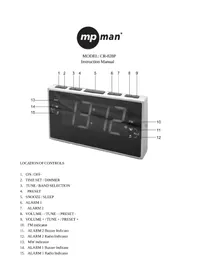
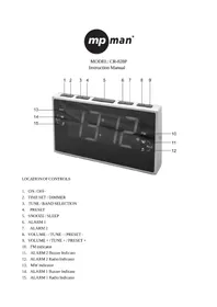
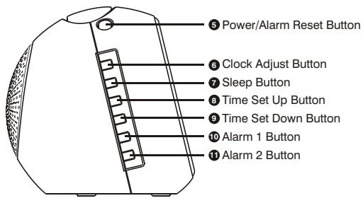
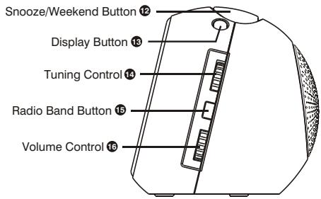
Controls and Indicators

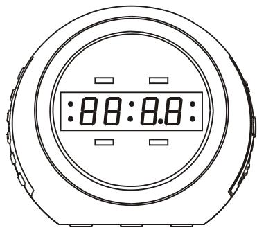
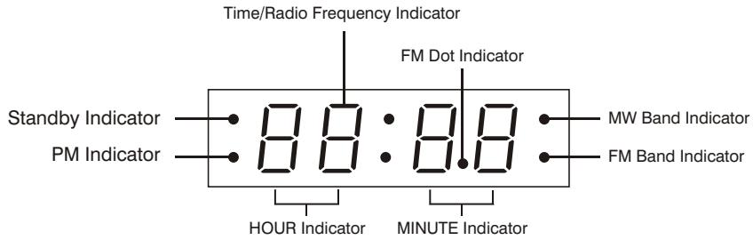
LED Display
Battery Backup Installation
Memory Backup
To insert 1.5V x 2, R03S/ AAA or equivalent batteries in the battery compartment at the bottom of the unit. It is used to backup the memory of the main CPU.
Note: You should replace the battery every six months, or after any extended power outage that could drain the battery power.
Setting Clock Time
- When you first plug the unit into the AC outlet, the unit will be in standby mode.
- Press & hold the C-ADJ Button more than 2 seconds, the
HOURLED indicator will flash and then press the Time SetUpor Time SetDownbutton for hour adjustment. - Press the C-ADJ Button to confirm the Hour set. Then, the MINUTE LED indicator will flash and then press the Time Set \Up\ or Time Set \Down\ button for minute adjustment.
- Press the C-ADJ Button again to confirm the clock time. Then, the
WEEK DAYLED indicatord1will flash then press the Time SetUpor Time SetDownbutton for week day adjustment.(d1means Monday andd7means Sunday) - Press the C-ADJ Button to confirm the Weekday set.
Listening to Radio
Tuner Information
This system features a normal MW/FM analog tuning system. Unlike a digital tuner, it does not automatically lock in on the exact frequency of a station. However instead of a dial scale and a moving dial pointer we have included a digital frequency display to help you tune more accurately. Do not be concerned if you cannot easily tune the display to the exact frequency of your favourite stations, especially on the MW band. Slowly rotate the TUNING control until the display approaches the frequency of the desired station and stop when get the strongest, noise free reception-even if the display is not indicating the exact frequency of desired station.
Radio Operation
Press the POWER / ALARM RESET button on the unit to switch the unit ON.
- The LED Clock Display will show the Radio frequency.
- Press the BAND button to select the MW or FM. (MW/FM LED indicator will appear on the display.)
- Select the desired wave band range with the TUNING CONTROL knob. The display will show the exact frequency of desired station. After 10 seconds, the display will go back to Real Time Clock.
Listening to Radio
ANTENNA
FM
For FM reception there is a built-in FM antenna wire at the rear of the unit. Unravel the wire and move it around to obtain the best reception.
MW
The MW bar antenna is inside the cabinet. To improve MW reception, you may have to move or slightly rotate the main unit until you obtain in best reception.
Sleeping to Radio
This unit features a radio sleep timer which can be programmed to play the radio for a set amount of time(maximum 90 minutes) before automatically turning off.
- During
RADIOplaying, press the SLEEP button to switch on the sleep timer. TheSLEEPLED indicator will light on. - Press & hold the SLEEP Button more than 2 seconds to select the desire sleep time cyclically from 90, 80, 70 .... to 1 minute.

- To cancel the SLEEP function, press the SLEEP button again, the 'SLEEP' LED indicator will light off.
Operating the Alarms
ALARM setting
- Press & hold the ALARM 1 button more than 2 seconds, the
HOUR&ALARM 1LED indicators will flash and then press the Time SetUPor Time SetDOWNButton for hour adjustment. - Press the ALARM 1 button to confirm the Hour set. Then, the
MINUTE&ALARM 1LED indicators will flash and then press the Time SetUPor Time SetDOWNbutton for minute adjustment. Press the ALARM 1 button again to confirm theALARM 1setting. - Press & hold the ALARM 2 button more than 2 seconds, the
HOUR&ALARM 2LED indicators will flash and then press the Time SetUPor Time SetDOWNbutton for hour adjustment. - Press the ALARM 2 button to confirm the Hour set. Then, the
MINUTE&ALARM2LED indicators will flash and then press the Time SetUPor Time SetDOWNbutton for minute adjustment. - Press the ALARM 2 button again to confirm the 'ALARM 2' setting.
Setting the Sound of the ALARM 1 and ALARM 2
Press the ALARM 1 or ALARM 2 button to set the sound of the alarm.
- Press the
ALARM 1button once, theALARM 1of RED LED indicator will light on, and the sound ofALARM 1inBUZZER. - Press the
ALARM 1button again, theALARM 1of YELLOW LED indicator will Light on, and the sound ofALARM 1inRADIO. - To cancel the
ALARM 1, press theALARM 1button again, theALARM 1LED indicator will light off. - Repeat the above steps 1 to 3 to set the sound of the
ALARM 2
Operating the Alarms
Stopping & Resetting the ALARM
Press the POWER/ALARM RESET button once to stop the sound of the ALARM 1 or ALARM 2 and it will automatic activate after 24 hours.
Snoopze operation
The SNOOZE function will temporarily switch off the alarm for approximately 9 minutes, this is repeatable for a duration in one hour of alarm cycle.
ALARM off
Alarm active - press the POWER/ALARM RESET or SNOOZE button to stop the sound first. Then, press the ALARM 1 or ALARM 2 button till the ALARM indicators light off.
Alarm non-active - press the ALARM 1 or ALARM 2 button till the ALARM indicators light off.
Weekend Sleep function
When the Alarm is under non-active mode, Press the SNOOZE/ WEEKEND BUTTON to enable /disable weekend sleep function. If weekend sleep function is on, alarm will not function on SAT and SUNDAY even though the alarm timer is enabled and the time is matched.
Display Mode setting
Press the DISPLAY button changing the display as shown below.
- In the Standby mode:
ALARM 1display >>ALARM 2display >> Clock display. - In the Radio mode: Radio frequency >>
ALARM 1display >>ALARM 2display >> remain time of SLEEP Timer >> Clock display.
IMPORTANT
The wires in the mains lead are coloured in accordance with the following code: -BLUE NEUTRAL BROWN-LIVE
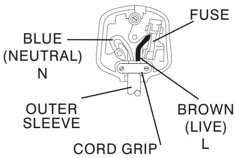
If your product is fitted with a moulded plug which requires replacement please cut off the plug and dispose of safety.
The replacement plug should then be rewired as shown in diagram.
As the colours of the wires in the mains lead of this apparatus may not correspond with the coloured markings identifying the terminals in your plug, proceed as followings:-
The wire which is coloured blue must be connected to the terminal which is marked with the letter N or coloured black.
The wire which is coloured brown must be connected to the terminal which is marked with the letter L or colouredred.
No connection is to be made to the earth terminal of the plug.
If a 13AMP (BS 1363) Plug is used a 3 AMP Fuse must be fitted, or if any other type of Plug is used a 3 OR5 AMP Fuse must be fitted, either in the Plug or Adaptor, or on the Distribution Board.