TSC 6000 - Haut-parleur FBT - Notice d'utilisation et mode d'emploi gratuit
Retrouvez gratuitement la notice de l'appareil TSC 6000 FBT au format PDF.

| Type de produit | Poste d'urgence tactile pour évacuation et annonces |
| Marque | FBT |
| Modèle | TSC 6000 (EN) |
| Nombre de zones sélectionnables | 1 à 216 (20 à 60 touches zone + 6 touches fonction) |
| Niveau de sortie typique | 300 mV |
| Réponse en fréquence | 20 Hz – 20 kHz |
| Distorsion | < 1 % |
| Filtre Low Cut | -10 dB à 100 Hz |
| Rapport signal/bruit | > 60 dB |
| Connexion | RJ45 (IN/OUT) avec câble CAT5e SF/UTP blindé |
| Tension d'alimentation | 24 Vcc (via câble CAT5 ou alimentation locale) |
| Consommation maximale | 165 mA @ 24 Vcc |
| Dimensions (L × H × P) | 230 × 80 × 200 mm |
| Poids net (sans micro) | 1,61 kg |
| Affichage | Écran tactile rétroéclairé |
| Témoins lumineux | ALARM (rouge), FAULT SYS (jaune), FAULT UNIT (jaune), DIS (jaune), BUSY (jaune), POWER LOC (vert), POWER REM (vert) |
| Fonctions principales | Appels de service en vivavoce, messages d'urgence en vivavoce, messages d'évacuation/allerte préenregistrés, sélection de zones, reset/silence |
| Microphone compatible | FMG 2000 (à col de cygne) ou FMH 2000 (palm avec PTT) |
| Configuration | Programmation des touches fonction, des noms de zones, des niveaux audio et de l'adresse |
| Sécurité | Bouton d'urgence protégé, priorité des appels, arrêt d'urgence par RESET |
FOIRE AUX QUESTIONS - TSC 6000 FBT
Questions des utilisateurs sur TSC 6000 FBT
0 question sur cet appareil. Repondez a celles que vous connaissez ou posez la votre.
Poser une nouvelle question sur cet appareil
Téléchargez la notice de votre Haut-parleur au format PDF gratuitement ! Retrouvez votre notice TSC 6000 - FBT et reprennez votre appareil électronique en main. Sur cette page sont publiés tous les documents nécessaires à l'utilisation de votre appareil TSC 6000 de la marque FBT.
MODE D'EMPLOI TSC 6000 FBT
FBT
TSC 6000/EN
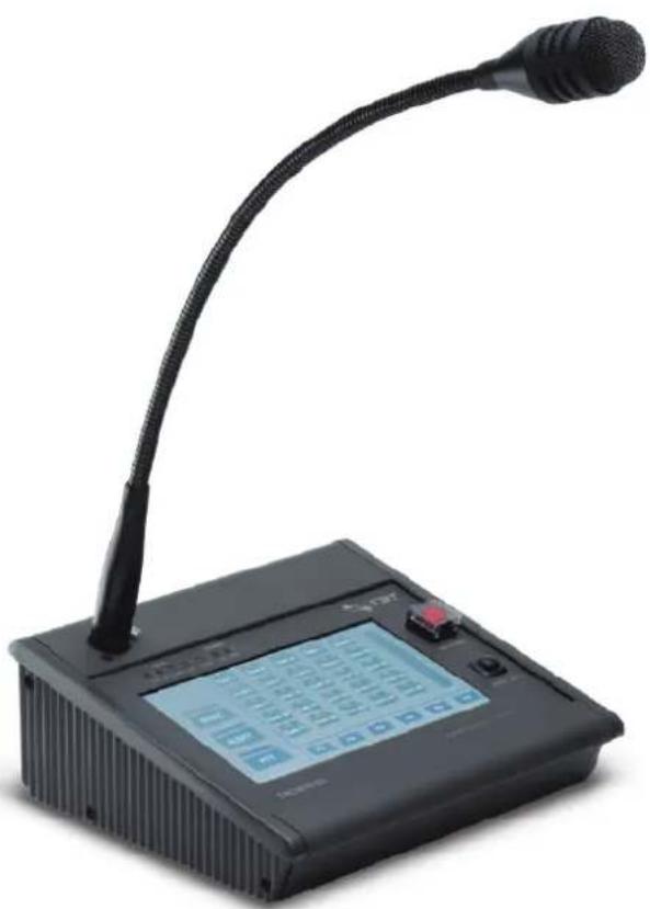
natural_image
Black desktop computer with a curved black neck and digital display showing a keypad (no visible text or symbols on the device body)EN 54-16:2008
EN 54-16:2008
Cert. Nr. 0068-CPR-044/2016
Declaration of Performance (DoP)
available on the website: www.fbt.it
TOUCH SCREEN
MICROPHONE STATION
CODE: 41151
rev.2_#02-2025
ITA / MANUALE D'USO
ENG / OPERATING MANUAL
pag.
DESCRIZIONE GENERALE 1
COLLEGAMENTI 2
MODALITÀ D'USO 5
IMPOSTAZIONI E REGOLAZIONI 12
CARATTERISTICHE TECNICHE 16
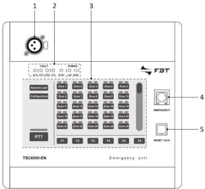
1. DESCRIZIONE GENERALE
Le postazioni touch screen per chiamate d'emergenza TSC6000-EN permettono l'invio di messaggi in viva voce e di messaggi di evacuazione/allerta pre-registrati.
L'ampio display retroilluminato consente la gestione e la personalizzazione delle chia-mate su tutte le zone dell'impianto, mentre appositi Led forniscono le principali informazioni sullo stato del sistema d'emergenza e dei guasti.
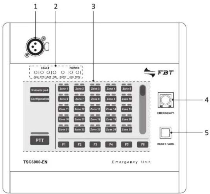
1.1 Riferimenti numerati
1) Presa per microfono a stelo o palmare.
2) LED indicatori di stato.
3) Display touch screen.
4) Pulsante d'emergenza.
5) Pulsante di reset.
6) Connettore per alimentazione esterna 24Vcc.
7) Connettori ingresso/uscita.
text_image
1 2 3 FAULT POWER FBT Numeric pad Configuration Zone 1 Zone 2 Zone 3 Zone 4 Zone 5 Zone 6 Zone 7 Zone 8 Zone 9 Zone 10 Zone 11 Zone 12 Zone 13 Zone 14 Zone 15 Zone 16 Zone 17 Zone 18 Zone 19 Zone 20 Zone 21 Zone 22 Zone 23 Zone 24 Zone 25 PTT F1 F2 F3 F4 F5 F6 TSC6000-EN Emergency Unit EMERGENCY RESET/ACK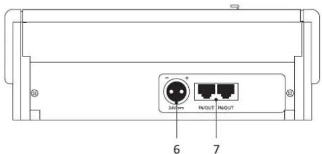
text_image
6 7Ciascuna postazione deve essere com- pletata con il microfono aggiuntivo (non compreso) a scelta fra i seguenti modelli:

FMG 2000
Microfono dinamico a stelo flessibile

natural_image
Diagram of a solenoid connected to a device labeled FMH 2000 (no text or symbols on the diagram itself)Microfono dinamico palmare con tasto P.T.T.
2. CONNESSIONI
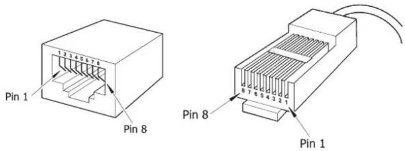
I collegamenti delle postazioni devono essere realizzati con cavi CAT5e SF/UTP con calza di schermo e connettore schermato STP.
text_image
Pin 1 Pin 8 Pin 8 Pin 1! Importante
Non sono ammessi cavi incrociati (cross-cable).
Tutti i connettori devono essere di tipo RJ45 schermato.
Gli standard EIA/TIA T568A e EIA/TIA T568B prevedono per tali cavi (e relativi connettori RJ45) le piedinature e colorazioni riportate in tabella. Viene inoltre indicata la piedinatura dei connettori d'ingresso-uscita IN/OUT (10).
| T568A | T568B | IN/OUT | |
| PIN | Colore | Colore | Funzione |
| 1 | Bianco/Verde | Bianco/Arancio | Audio + |
| 2 | Verde | Arancio | Audio - |
| 3 | Bianco/Arancio | Bianco/Verde | GND |
| 4 | Blu | Blu | Non collegato |
| 5 | Bianco/Blu | Bianco/Blu | Non collegato |
| 6 | Arancio | Verde | +Vcc |
| 7 | Bianco/Marrone | Bianco/Marrone | Seriale + |
| 8 | Marrone | Marrone | Seriale - |
| Schermo | Schermo | Schermo | GND |
2.1 Collegamento a sistemi compatti Serie VAIE 6500
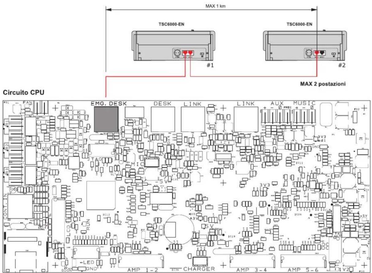
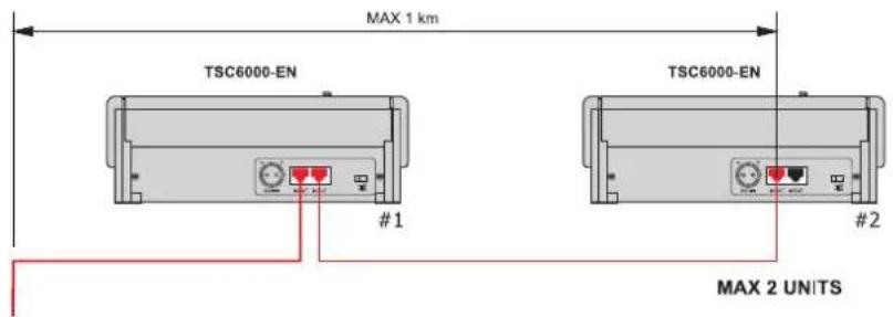
Le postazioni TSC6000-EN devono essere collegate alla presa 'EMG.DESK' del sistema compatto VAIE 6500, ed utilizzate in alternativa alle postazioni d'emergenza Serie FMD. In ogni cestello possono essere presenti un massimo di 2 postazioni.
text_image
MAX 1 km TSC6000-EN TSC6000-EN #1 #2 MAX 2 postazioni Circuito CPU EMG. DESK DESK LINK LINK AUX MUSIC 5 V 3 V3 3 V3 3 V11 3 V12 3 V13 3 V14 3 V15 3 V16 3 V17 3 V18 3 V19 3 V20 AMP 1-2 CHARGER AMP 3-4 AMP 5-6 V202.2 Collegamento a controller VAC 2006
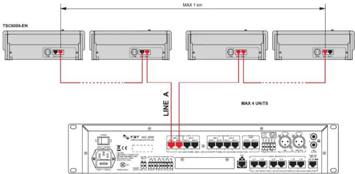
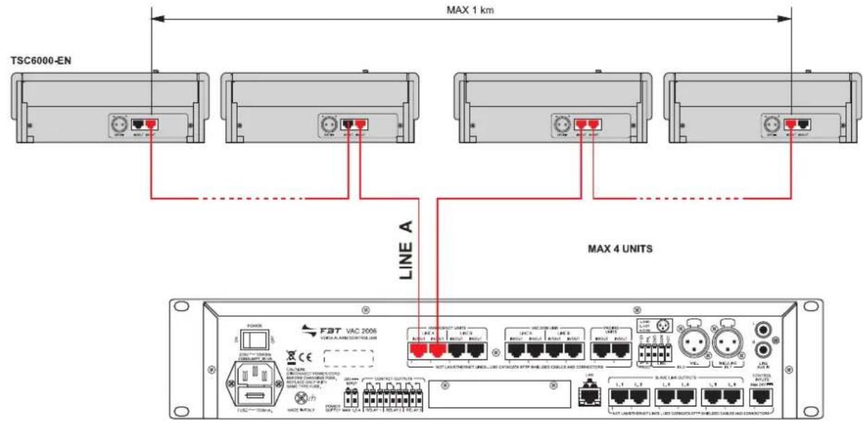
Le postazioni TSC6000-EN devono essere collegate alla presa "EMERGENCY UNITS" (LINEA A - impostazione obbligatoria) del controller VAC 2006, per un massimo di 7 unità.
text_image
TSC6000-EN MAX 1 km LINE A MAX 4 UNITS FAT VAC 2006 CE LPG MOSI WAL SHEV MOSI WAL SHEV MOSI WAL SHEV MOSI WAL SHEV MOSI WAL SHEV MOSI WAL SHEV MOSI WAL SHEV MOSI WAL SHEV MOSI WAL SHEV MOSI WAL SHEV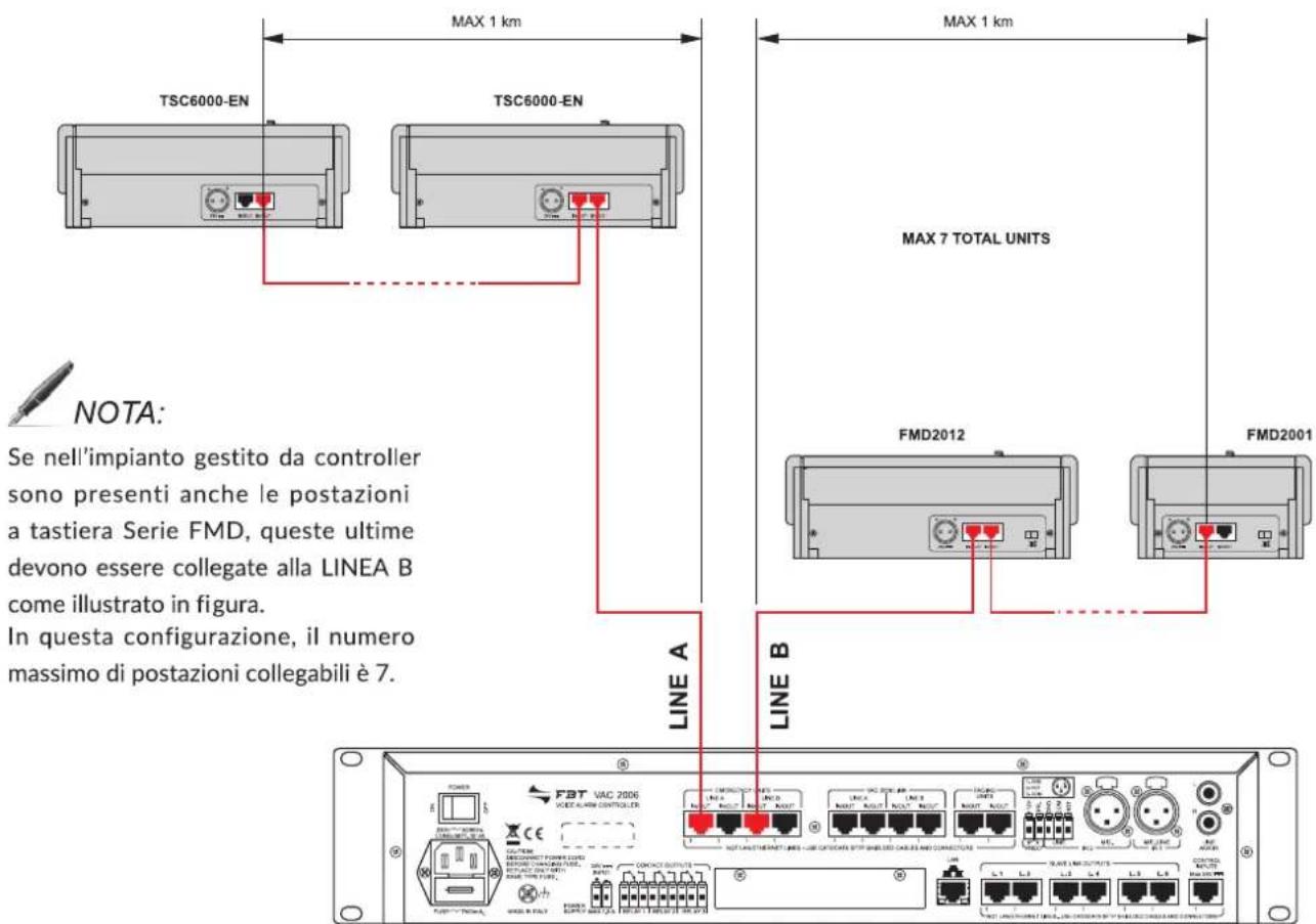
text_image
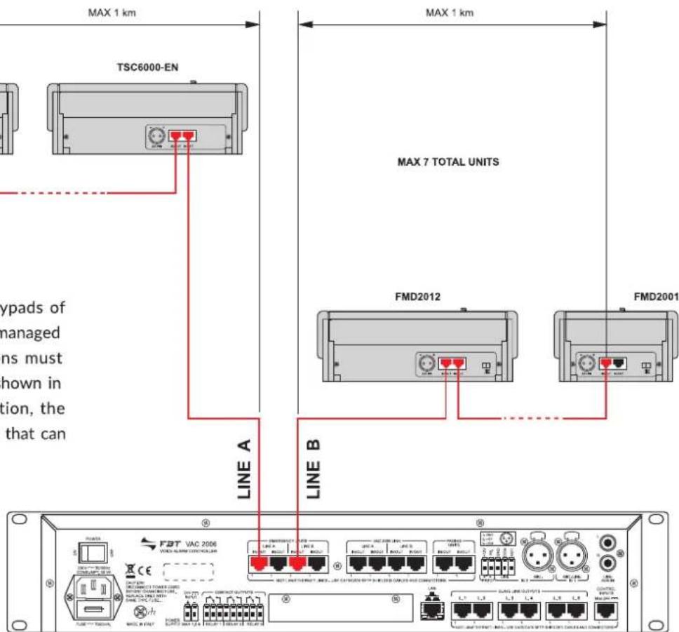
MAX 1 km TSC6000-EN TSC6000-EN MAX 7 TOTAL UNITS FMD2012 FMD2001 NOTE: Se nell'impianto gestito da controller sono presenti anche le postazioni a tastiera Serie FMD, queste ultime devono essere collegate alla LINEA B come illustrato in figura. In questa configurazione, il numero massimo di postazioni collegabili è 7. LINE A LINE B F3T VAC 2006 VOCER ALARM CONTROLLER CONCHO OUTPUTS NUTLA CHATUERATE LINEA LINE COTOCARE SFTP SHABLED CASES AND CONNECTORS LINE A LINE B LINE A LINE B LINE A LINE B LINE A LINE B LINE A LINE B LINE A LINE B LINE A LINE B LINE A LINE B LINE A LINE B2.3 DIMENSIONAMENTO
Nella tabella sottostante viene illustrato un esempio che indica i limiti massimi di lunghezza totale che possono essere mantenuti per i collegamenti utilizzando cavi CAT5e SF/UTP con calza di schermo:
| n° postazioni TSC6000/EN - VAIE 6500 TSC6000/EN - VAC 2006 | ||
| 1 300 m 300 m | ||
| 2 200 m 200 m | ||
| 3 100 m | ||
Per impianti che prevedono un numero maggiore e/o distanze superiori rispetto a quelle riportate, ciascuna di queste postazioni dovrà essere alimentata anche localmente con un'alimentazione continua stabilizzata di 24Vcc/500mA, utilizzando l'apposita presa sul lato posteriore (6).
3. USO
Le postazioni TSC6000-EN sono dotate di una serie di LED (2) atti a segnalare gli stati operativi del sistema. Di seguito vengono indicate nel dettaglio le corrispondenze LED/stato.
| ALARM | Rosso | Indica lo “Stato di allarme” in corso nel sistema. | |
| FAULT SYS | Giallo | Segnala la presenza dello stato di guasto dell’apparecchio a cui la postazione è collegata. | |
| FAULT UNIT | Giallo | Indica un guasto generico alla postazione stessa.Consultare il menu “Unit fault list” per visualizzare il tipo di guasto (vedi par. 4.5 Lista guasti, pag. 17) | |
| DIS | Giallo | Segnala uno “Stato di disabilitazione” attivo.Indica la presenza di almeno una zona in cui è disabilitato l’invio di messaggi d’emergenza. | |
| BUSY | Giallo | Spento: sistema libero (nessuna postazione in chiamata).Acceso fisso: indica che un’altra postazione con priorità uguale o maggiore sta occupando il sistema.Acceso lampeggiante: indica che un’altra postazione con priorità minore sta occupando il sistema; durante una chiamata broadcast, invece, indica la durata del segnale di preavviso | |
| POWER LOC | Verde | Indica la presenza dell’alimentazione locale in corrente continua applicata alla presa esterna della postazione. | |
| POWER REM | Verde | Indica la presenza dell’alimentazione fornita da un VAIE 6500 o da un VAC 2006 tramite il cavo CAT5. |
NOTA:
Per maggiori informazioni sugli stati operativi del sistema, quali "Stato di allarme" o "Stato di disabilitazione", consultare la Sezione "Operatività e nomenclatura" del manuale dell'unità di controllo collegata.
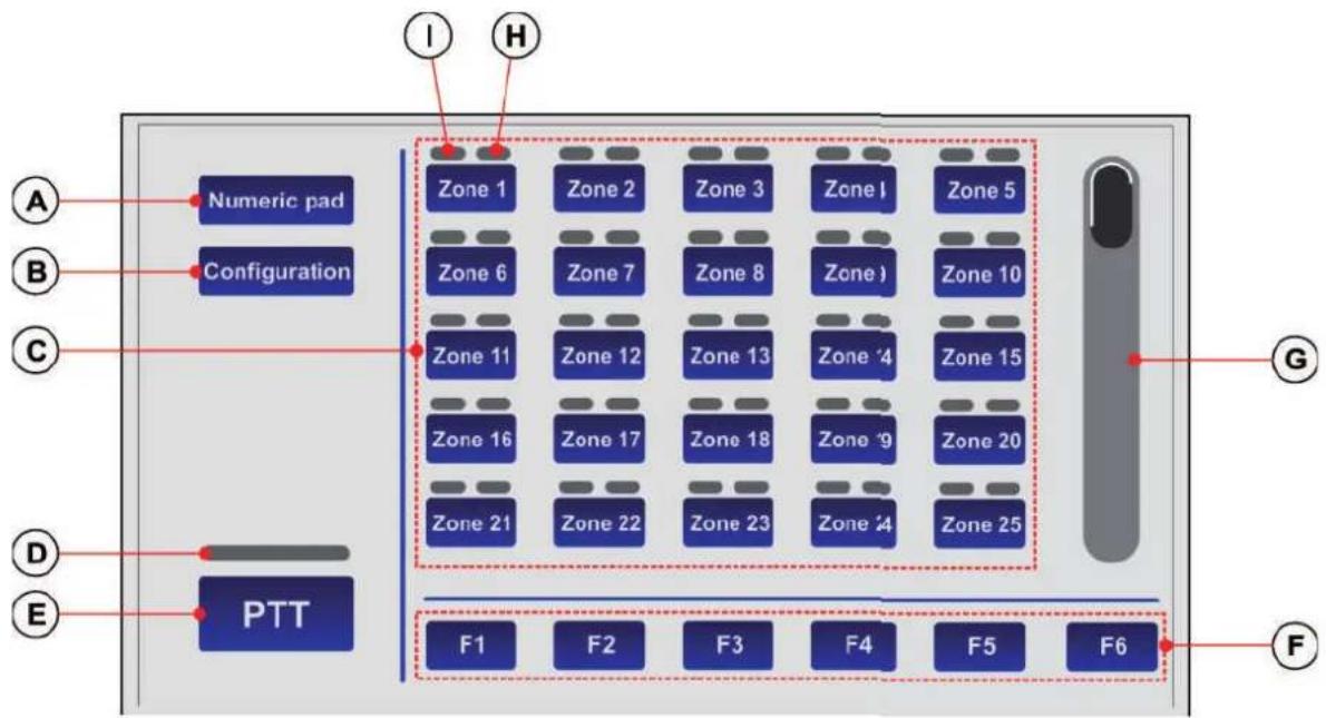
Tutte le operazioni di selezione zone, configurazione e personalizzazione vengono effettuate sul display touch screen della postazione. La modalità di visualizzazione principale è denominata "KEY PAD". Le stesse operazioni possono essere effettuate anche utilizzando la visualizzazione "NUMERIC PAD" (solo in modalità broadcast); in questo caso l'utente può digitare direttamente il numero di zona.
text_image
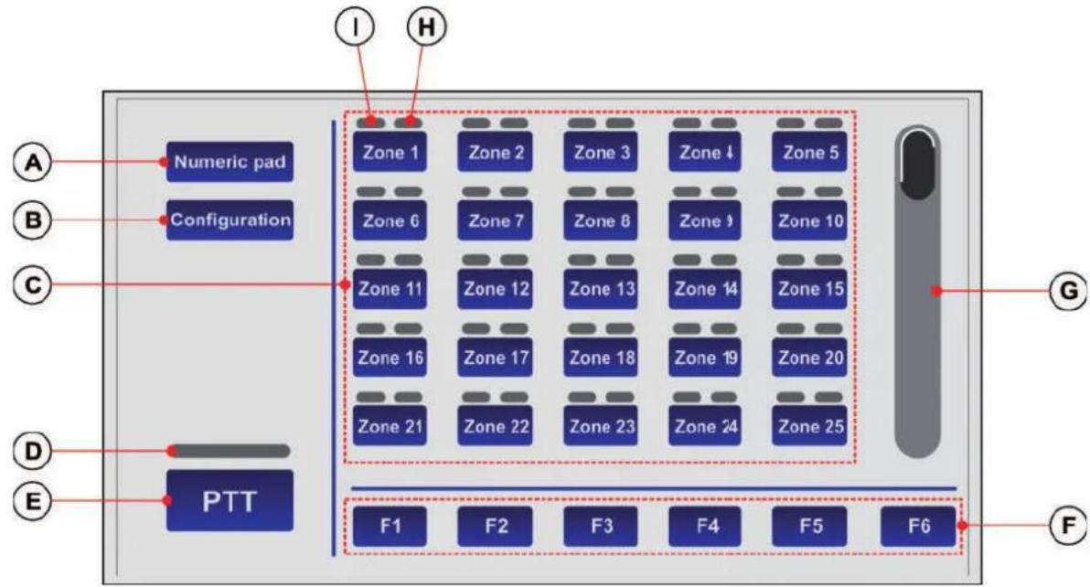
A B C D E Numeric pad Configuration PTT I H Zone 1 Zone 2 Zone 3 Zone I Zone 5 Zone 6 Zone 7 Zone 8 Zone 9 Zone 10 Zone 11 Zone 12 Zone 13 Zone 14 Zone 15 Zone 16 Zone 17 Zone 18 Zone 19 Zone 20 Zone 21 Zone 22 Zone 23 Zone 24 Zone 25 F1 F2 F3 F4 F5 F6 G F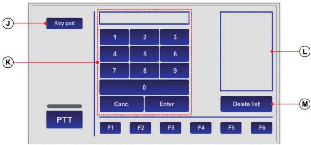
text_image
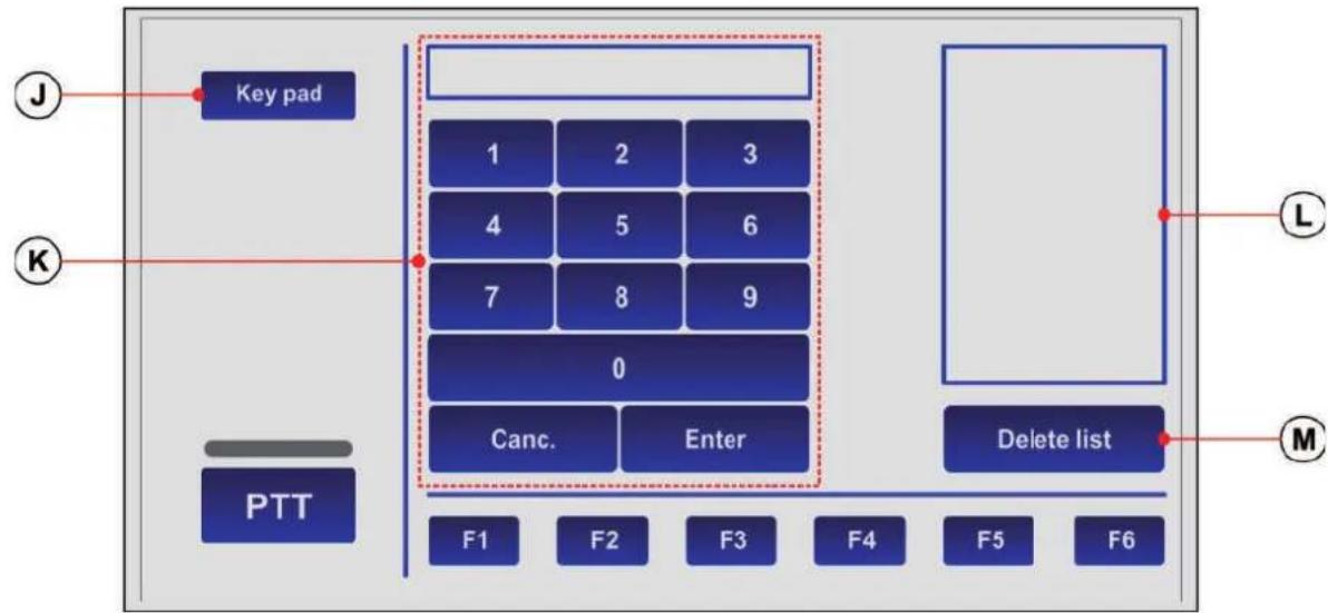
Key pad 1 2 3 4 5 6 7 8 9 0 Canc. Enter PTT F1 F2 F3 F4 F5 F6 Delete list L MModalità NUMERIC PAD
A. Tasto per il passaggio alla mod. NUMERIC PAD.
B. Tasto di accesso al menu di configurazione.
C. Tastiera selezione zone.
D. Indicatore di stato della chiamata a viva voce
• spento: PTT non attivato
- acceso: PTT attivato
E. Tasto per invio chiamata a viva voce (PTT).
F. Tasti funzione.
G. Barra di scorrimento.
H. Indicatore di stato della zona
I. Indicatore tipologia chiamata
J. Tasto per il passaggio alla mod. KEY PAD.
K. Tastierino numerico.
L. Lista delle zone selezionate.
M. Tasto per cancellazione lista.
La postazione consente di effettuare nell'impianto le seguenti operazioni:
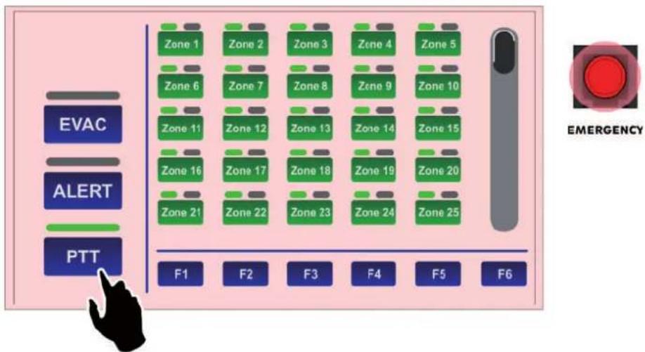
3.1 Invio di chiamate di servizio (broadcast) in viva voce.
3.2 Invio di messaggi d'emergenza in viva voce.
3.3 Invio di messaggi d'evacuazione/allerta pre-registrati.
3.4 Invio selettivo sulle zone di diffusione.
3.5 Reset dei messaggi d'emergenza / Silenziamento cicalino per riconoscimento guasto.
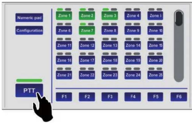
3.1 Invio di chiamate di servizio (broadcast) in viva voce
Per inviare sulle zone di diffusione un messaggio di servizio a viva voce, è sufficiente premere e tenere premuto il tasto PTT (E): l'indicatore verde si accende ad indicare che il microfono è attivo. Prima di parlare, si ricorda di attendere lo spegnimento del led giallo BUSY, che indica il termine del segnale di preavviso. Nel caso in cui non sia stata selezionata preventivamente alcuna zona, la chiamata viene inviata su tutte le zone dell'impianto, quindi sul display tutti gli indicatori (I) diventeranno di colore verde.
text_image
Numeric pad Configuration Zone 1 Zone 2 Zone 3 Zone 4 Zone i Zone 6 Zone 7 Zone 8 Zone 9 Zone 10 Zone 11 Zone 12 Zone 13 Zone 14 Zone 15 Zone 16 Zone 17 Zone 18 Zone 19 Zone 20 Zone 21 Zone 22 Zone 23 Zone 24 Zone 25 PTT F1 F2 F3 F4 F5 F6Nel caso si volesse indirizzare il messaggio solo in alcune zone o gruppi di zone, fare riferimento al paragrafo 3.4 Invio selettivo sulle zone di diffusione (pag. 12).
text_image
Numeric pad Configuration Zone 1 Zone 2 Zone 3 Zone 4 Zone 5 Zone 6 Zone 7 Zone 8 Zone 9 Zone 10 Zone 11 Zone 12 Zone 13 Zone 14 Zone 15 Zone 16 Zone 17 Zone 18 Zone 19 Zone 20 Zone 21 Zone 22 Zone 23 Zone 24 Zone 25 PTT F1 F2 F3 F4 F5 Numeric pad Configuration Zone 1 Zone 2 Zone 3 Zone 4 Zone 5 Zone 6 Zone 7 Zone 8 Zone 9 Zone 10 Zone 11 Zone 12 Zone 13 Zone 14 Zone 15 Zone 16 Zone 17 Zone 18 Zone 19 Zone 20 Zone 21 Zone 22 Zone 23 Zone 24 Zone 26 PTT F1 F2 F3 F4 F5 F6 Per terminare la chiamata, rilasciare il tasto PTT.3.2 Invio di messaggi d'emergenza in vivavoce
Per inviare sulle zone di diffusione un messaggio d'emergenza a viva voce, è necessario prima di tutto mettere in condizione di emergenza la postazione:
- Sollevare il coperchietto di protezione del tasto EMERGENCY (4) e premerlo: il tasto si accende in modo fisso ad indicare la condizione di emergenza attivata, lo sfondo del display cambia colore e tutti i tasti zona diventano verdi ad indicare la preselezione generale.
flowchart
graph TD
    A["EVAC"] --> B["Zone 1"]
    A --> C["Zone 2"]
    A --> D["Zone 3"]
    A --> E["Zone 4"]
    A --> F["Zone 5"]
    G["ALERT"] --> H["Zone 6"]
    G --> I["Zone 7"]
    G --> J["Zone 8"]
    G --> K["Zone 9"]
    G --> L["Zone 10"]
    M["PTT"] --> N["Zone 11"]
    M --> O["Zone 12"]
    M --> P["Zone 13"]
    M --> Q["Zone 14"]
    M --> R["Zone 15"]
    S["F1"] --> T["Zone 21"]
    S --> U["Zone 22"]
    V["F2"] --> W["Zone 23"]
    X["F3"] --> Y["Zone 24"]
    Z["F4"] --> AA["Zone 25"]
    AB["F5"] --> AC["EMER"]
    AD["F6"] --> AE["EMER"]
- Premere e tenere premuto il tasto PTT: il led rosso ALARM si accende, l'indicatore verde indica che è possibile parlare al microfono. Nel caso in cui non sia stata selezionata preventivamente alcuna zona, il messaggio verrà diffuso su tutte le zone. Nel caso si volesse indirizzare il messaggio solo in alcune zone o gruppi di zone, fare riferimento al paragrafo 3.4 Invio selettivo sulle zone di diffusione (pag. 12).
N.B.: Si ricorda che il tasto PTT ha la priorità su eventuali messaggi pre-registrati in corso.

flowchart
graph TD
    A["Zone 1"] --> B["F1"]
    C["Zone 2"] --> D["F2"]
    E["Zone 3"] --> F["F3"]
    G["Zone 4"] --> H["F4"]
    I["Zone 5"] --> J["F5"]
    K["Zone 6"] --> L["F6"]
    M["Zone 7"] --> N["F1"]
    O["Zone 8"] --> P["F2"]
    Q["Zone 9"] --> R["F3"]
    S["Zone 10"] --> T["F4"]
    U["Zone 11"] --> V["F5"]
    W["Zone 12"] --> X["F6"]
    Y["Zone 13"] --> Z["F1"]
    AA["Zone 14"] --> AB["F2"]
    AC["Zone 15"] --> AD["F3"]
    AE["Zone 16"] --> AF["F4"]
    AG["Zone 17"] --> AH["F5"]
    AI["Zone 18"] --> AJ["F6"]
    AK["Zone 19"] --> AL["F1"]
    AM["Zone 20"] --> AN["F2"]
    AO["Zone 21"] --> AP["F3"]
    AQ["Zone 22"] --> AR["F4"]
    AS["Zone 23"] --> AT["F5"]
    AU["Zone 24"] --> AV["F6"]
    AW["PTT"] --> AX["F1"]
Per terminare il messaggio d'emergenza in viva voce, rilasciare il pulsante e premere nuovamente il pulsante EMERGENCY, avendo cura di rischiudere lo sportellino.
NOTA: uno stato d'emergenza può essere interrotto solo da una postazione a priorità superiore oppure dai comandi locali del sistema (VAIE 6500 o VAC 2006).
Lo stato del tasto EMERGENCY indica la condizione del sistema:
- spento = emergenza disattivata.
- lampeggiante = emergenza in corso, attivata da un'altra postazione o da comandi locali del sistema.
- acceso fisso = emergenza manuale attivata dalla postazione stessa.
Tutti i tasti sono attivi per consentire all'operatore di gestire l'emergenza.
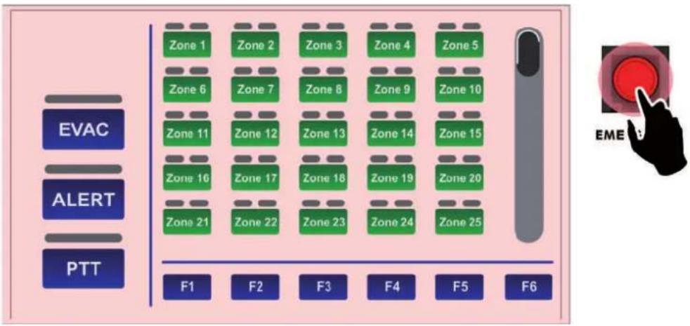
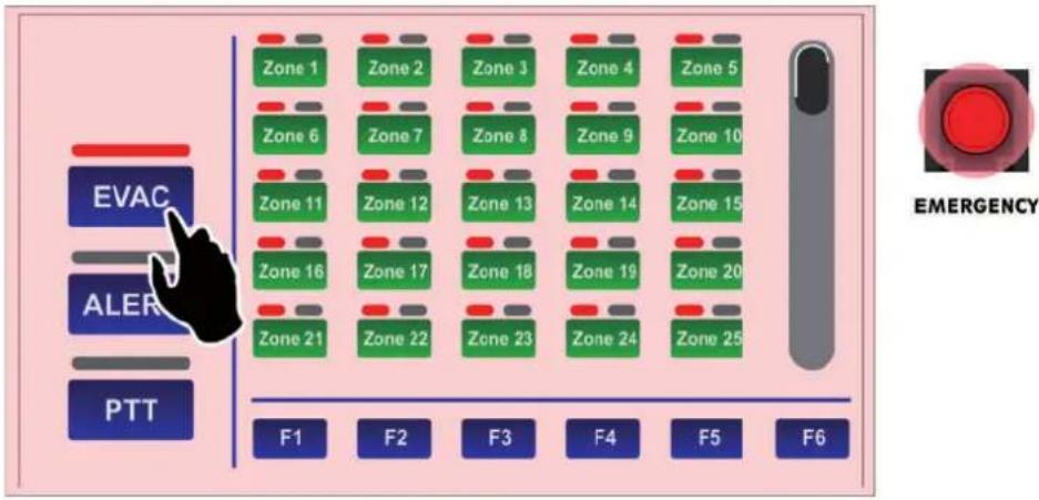
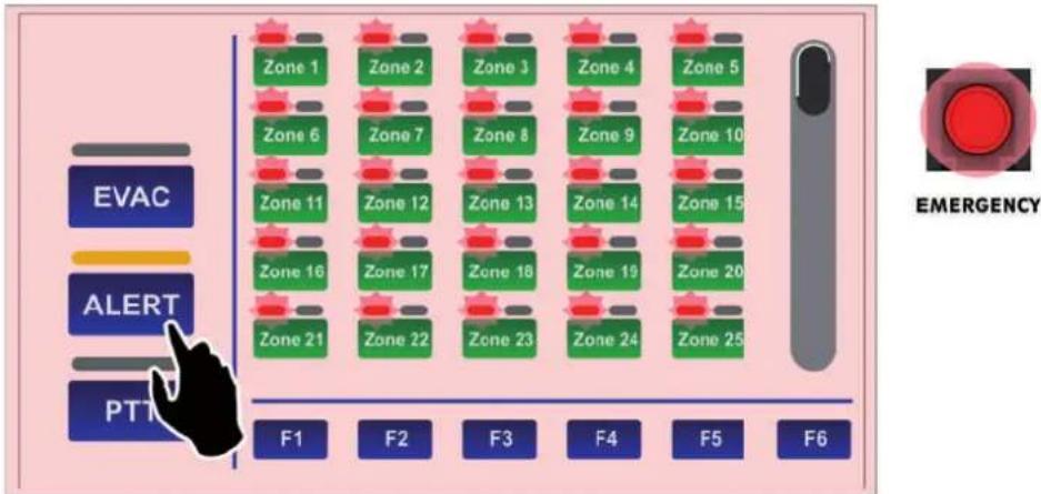
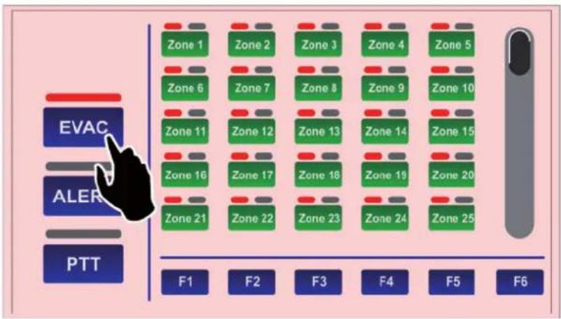
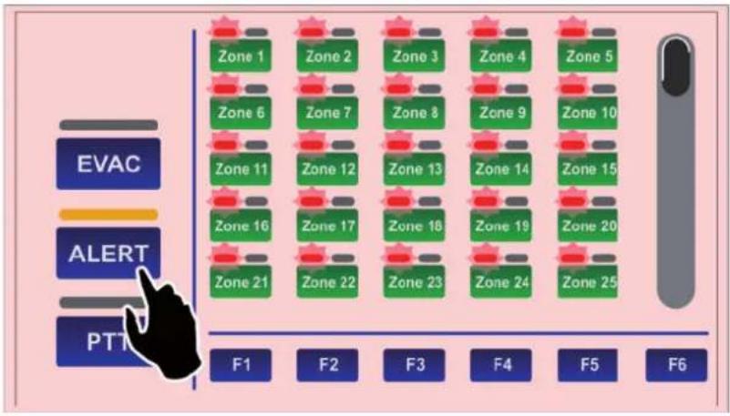
3.3 Invio di messaggi d'evacuazione/allerta pre-registrati
Per inviare messaggi d'evacuazione o d'allerta pre-registrati - archiviati nella memoria dell'unità di controllo collegata alla TSC6000-EN - dopo aver attivato la modalità di emergenza (vedi par. 3.2) premere ALERT o EVAC per inviare sulle zone di diffusione rispettivamente un messaggio d'allerta o d'evacuazione.
flowchart
graph TD
    A["EVAC"] --> B["Zone 1"]
    A --> C["Zone 2"]
    A --> D["Zone 3"]
    A --> E["Zone 4"]
    A --> F["Zone 5"]
    G["ALER"] --> H["Zone 6"]
    G --> I["Zone 7"]
    G --> J["Zone 8"]
    G --> K["Zone 9"]
    G --> L["Zone 10"]
    M["PTT"] --> N["Zone 11"]
    M --> O["Zone 12"]
    M --> P["Zone 13"]
    M --> Q["Zone 14"]
    M --> R["Zone 15"]
    S["F1"] --> T["Zone 16"]
    S --> U["Zone 17"]
    S --> V["Zone 18"]
    S --> W["Zone 19"]
    S --> X["Zone 20"]
    S --> Y["Zone 21"]
    S --> Z["Zone 22"]
    S --> AA["Zone 23"]
    S --> AB["Zone 24"]
    S --> AC["Zone 25"]
    AD["F2"] --> AE["F3"]
    AF["F4"] --> AG["F5"]
    AH["F6"] --> AI["F6"]
    AJ["EMERGENCY"] --> AK["F6"]
Gli indicatori (I) diventeranno di colore rosso: se selezionato il messaggio d'evacuazione (EVAC) a luce fissa, se selezionato il messaggio d'allerta (ALERT) a luce intermittente.
flowchart
graph TD
    A["Zone 1"] --> B["Zone 2"]
    B --> C["Zone 3"]
    C --> D["Zone 4"]
    D --> E["Zone 5"]
    F["Zone 6"] --> G["Zone 7"]
    G --> H["Zone 8"]
    H --> I["Zone 9"]
    I --> J["Zone 10"]
    K["Zone 11"] --> L["Zone 12"]
    L --> M["Zone 13"]
    M --> N["Zone 14"]
    N --> O["Zone 15"]
    P["Zone 16"] --> Q["Zone 17"]
    Q --> R["Zone 18"]
    R --> S["Zone 19"]
    S --> T["Zone 20"]
    U["Zone 21"] --> V["Zone 22"]
    V --> W["Zone 23"]
    W --> X["Zone 24"]
    X --> Y["Zone 25"]
    Z["F1"] --> AA["F2"] --> AB["F3"] --> AC["F4"] --> AD["F5"] --> AE["F6"]
Anche in questo caso, se non è stata selezionata preventivamente alcuna zona, il messaggio selezionato verrà diffuso per impostazione di default su tutte le zone; nel caso si volesse indirizzare il messaggio solo in alcune zone o gruppi di zone, fare riferimento al paragrafo 3.4 Invio selettivo sulle zone di diffusione (pag. 12). Per interrompere i messaggi pre-registrati tenere premuto il pulsante RESET/ACK f no alla disattivazione dei messaggi (circa 2 secondi).
Premendo nuovamente il pulsante EMERGENCY i messaggi saranno disattivati e la postazione uscirà dallo stato di emergenza; si rammenta di richiudere lo sportellino.
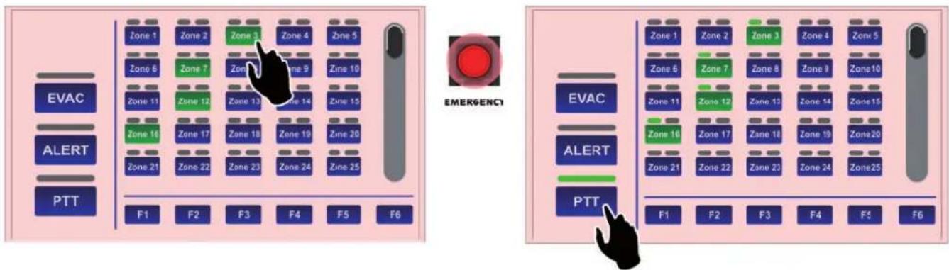
3.4 Invio selettivo sulle zone di diffusione
La tastiera della postazione TSC6000-EN può essere utilizzata per la pre-selezione di una o più zone sulle quali inviare comunicazioni in viva voce oppure inviare messaggi pre-registrati. Ciascun tasto-zona è corredato da tre indicatori che ne evidenziano lo stato:
| Indicatore | Colore | Condizione del sistema | Stato | Significato |
 | Rosso | Emergenza manuale attivata | Fisso, con led ALARM acceso | Annuncio pre-registrato d'evacuazione in corso |
 | Rosso | Emergenza manuale attivata | Lampeggiante, con led ALARM acceso | Annuncio pre-registrato d'allerta in corso |
 | Verde | Stato di quiete | Fisso | Annuncio di servizio a viva voce in corso |
 | Giallo | Stato di guasto | Lampeggiante | Zona in guasto o non disponibile per guasto amplif catore |
 | Giallo | Stato di guasto | Fisso | Zona impostata in “stato di disabilitazione” |
 | Verde (tasto) | Tutte | Fisso | Zona selezionata |
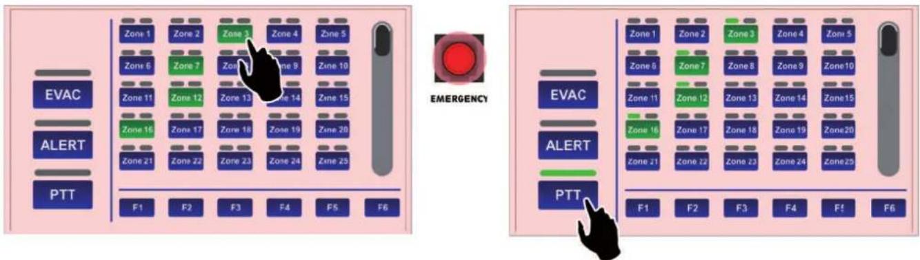
3.4.1 Invio selettivo di messaggi d'emergenza a viva voce
Dopo aver attivato l'emergenza con il tasto EMERGENCY (tutti i tasti zona diventano verdi ad indicare la preselezione generale) premere i pulsanti relativi alle zone desiderate, che rimarranno di colore verde a confermare la selezione avvenuta.
A questo punto, premere e mantenere premuto il tasto PTT: il microfono è attivato ed è possibile effettuare l'annuncio a viva voce.
text_image
EVAC ALERT PTT Zone 1 Zone 2 Zone 3 Zone 4 Zone 5 Zone 6 Zone 7 Zone 9 Zone 10 Zone 11 Zone 12 Zone 13 Zone 14 Zone 15 Zone 16 Zone 17 Zone 18 Zone 19 Zone 20 Zone 21 Zone 22 Zone 23 Zone 24 Zone 25 F1 F2 F3 F4 F5 F6 EMERGENCY EVAC ALERT PTT Zone 1 Zone 2 Zone 3 Zone 4 Zone 5 Zone 6 Zone 7 Zone 8 Zone 9 Zone10 Zone 11 Zone 12 Zone 13 Zone 14 Zone15 Zone 16 Zone 17 Zone 18 Zone 19 Zone20 Zone 21 Zone 22 Zone 23 Zone 24 Zone25 F1 F2 F3 F4 F5 F6Al termine dell'annuncio, rilasciare il tasto PTT e premere nuovamente EMERGENCY per uscire dallo stato di emergenza.
3.4.2 Invio selettivo di messaggi d'evacuazione/allerta pre-registrati
Dopo aver attivato l'emergenza con il tasto EMERGENCY (tutti i tasti zona diventano verdi ad indicare la preselezione generale) premere i pulsanti relativi alle zone desiderate, che rimarranno di colore verde a confermare la selezione avvenuta. A questo punto:
• per inviare un messaggio di evacuazione, premere EVAC.
• per inviare un messaggio di allerta, premere ALERT.
È possibile effettuare più volte l'operazione sopra descritta per aggiungere ulteriori zone sia in ALERT che in EVAC, tenendo in considerazione che la selezione EVAC di una zona è prioritaria rispetto all'ALERT.
3.4.3 Invio selettivo di messaggi di servizio a viva voce
Selezionare le zone desiderate, che diventeranno di colore verde.
Premere e tenere premuto il tasto PTT e attendere che il led BUSY si spenga ad indicare il termine del segnale di preavviso.
A questo punto, il microfono è attivato ed è possibile effettuare l'annuncio a viva voce.
Per terminare l'annuncio, rilasciare il tasto PTT.
3.4.4 Invio selettivo tramite tasti funzione
Con le stesse modalità e sequenze sopra riportate, sia per quanto riguarda l'emergenza che il broadcast di servizio, è possibile inviare messaggi/annunci su gruppi di zone preselezionate. A questo scopo, la postazione è fornita di 6 tasti funzione (F1 ÷ F6).
Per l'impostazione dei tasti funzione, fare riferimento al par. 4.1 Conf gurazione dei tasti funzione (pag. 14).
3.5 Reset dei messaggi d'emergenza / Silenziamento cicalino per riconoscimento guasto
Il tasto RESET/ACK (5) ha una funzionalità multipla in base allo stato del sistema:
Funzione RESET | Reset dei messaggi
Durante uno stato d'allarme in corso e con postazione in emergenza, tenendo premuto il tasto RESET/ACK per 2 secondi, consente di interrompere l'emissione dei messaggi (anche quelli richiamati dalle attivazioni degli ingressi di controllo) mantenendo comunque il sistema in stato d'emergenza.
Funzione ACK | Silenziamento del cicalino per riconoscimento del guasto
In presenza di guasti, premere brevemente il tasto RESET/ACK: il cicalino (buzzer) viene silenziato solo sulla postazione stessa, mantenendo comunque accesi i led relativi al guasto in corso.
La funzione è attiva in qualunque stato della postazione (emergenza o servizio).
In caso di ulteriore nuovo guasto, il cicalino riprende a suonare.
4. IMPOSTAZIONI E REGOLAZIONI
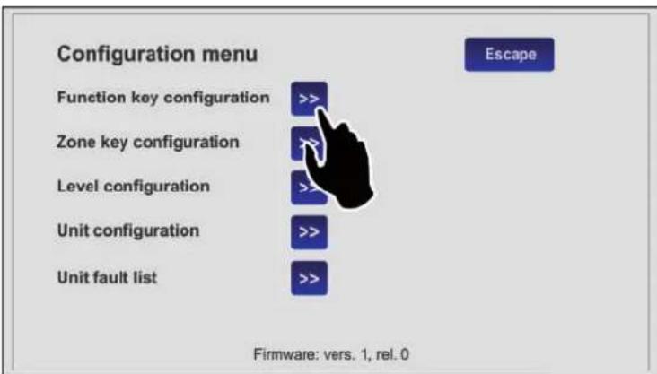
Premendo il tasto 'Configuration' (B) nella visualizzazione Key pad, è possibile accedere al menu di configurazione della TSC6000-EN. Per tornare alla schermata principale, premere su 'Escape'.

text_image
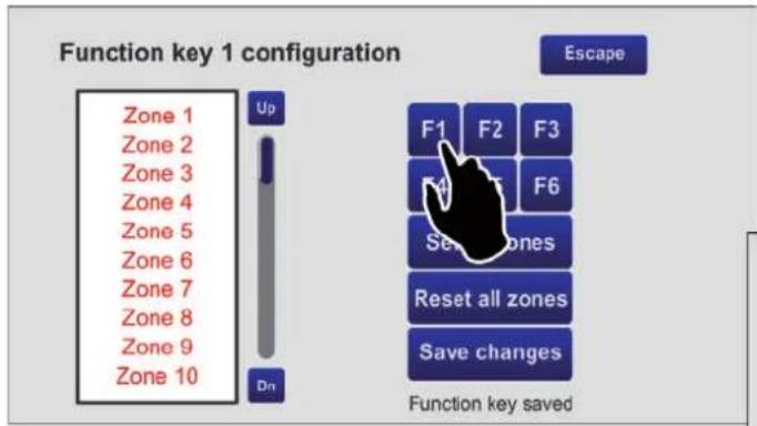
Configuration menu Function key configuration >> Zone key configuration Level configuration >> Unit configuration >> Unit fault list >> Escape Firmware: vers. 1, rel. 04.1 Configurazione dei tasti funzione (Function key configuration)
Questa schermata consente di abbinare le zone di diffusione ai tasti funzione da F1 a F6.
Utilizzando questa opzione, sarà possibile inviare i messaggi su un gruppo pre-selezionato di zone premendo un solo tasto.
NOTA: per impostazione di fabbrica, ogni tasto funzione richiama tutte le zone (colore verde).
Utilizzando il tasto "Reset all zones" è possibile rimuovere con un solo click questa impostazione (zone non abbinate, colore rosso).
text_image
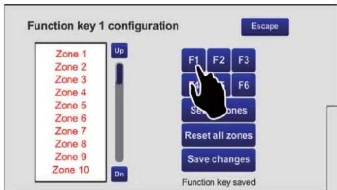
Function key 1 configuration Zone 1 Zone 2 Zone 3 Zone 4 Zone 5 Zone 6 Zone 7 Zone 8 Zone 9 Zone 10 Up Dn Escape F1 F2 F3 F4 F5 F6 Set zones Reset all zones Save changes Function key saved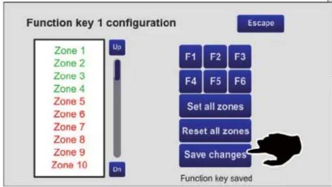
text_image
Function key 1 configuration Zone 1 Zone 2 Zone 3 Zone 4 Zone 5 Zone 6 Zone 7 Zone 8 Zone 9 Zone 10 Up Dn Escape F1 F2 F3 F4 F5 F6 Set all zones Reset all zones Save changes Function key savedPartendo da questa condizione, configuriamo ad esempio il tasto F1:
- Premere F1: sopra la lista appare la scritta "Function key 1 configuration" a conferma della selezione.
text_image
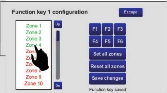
Function key 1 configuration Zone 1 Zone 2 Zone 3 Zone 4 Zone 5 Zone 6 Zone 7 Zone 8 Zone 9 Zone 10 Up D1 Escape F1 F2 F3 F4 F5 F6 Set all zones Reset all zones Save changes Function key saved- Utilizzare i tasti 'Up' e 'Dn' per scorrere l'elenco e selezionare le zone che si vogliono associare al tasto (nell'esempio 1 - 2 - 3 - 4).
- Premere 'Save changes' e quindi 'Escape' per ritornare al menu di configurazione.
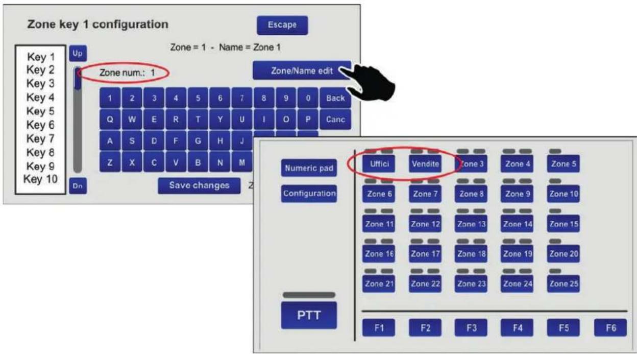
4.2 Configurazione tastiera zone (Zone key configuration)
Questa schermata consente di configurare singolarmente i 60 tasti a disposizione e di personalizzarne la denominazione.
Proviamo ad esempio a configurare il tasto n. 1 come relativo alla zona 1 e identifichiamolo come 'Uffici'.
text_image
Zone key 1 configuration Escape Zone = 1 - Name = Zone 1 Zone num.: 1 Zone/Name edit 1 2 3 4 5 6 7 8 9 0 Back Q W E R T Y U I O P Canc A S D F G H J K L / Enter Z X C V B N M - . space Dn Save changes Zone key saved- Selezionare la voce 'Key 1' dall'elenco dei tasti: sul display la scritta "Zone key 1 configuration" attesta che si sta operando sul tasto n. 1.
- Premere il tasto 'Zone/name edit' e quindi il tasto '1': apparirà la scritta "Zone num.: 1". Premere 'Enter' per confermare.
- Premere nuovamente il tasto 'Zone/Name edit' e digitare 'uffici': apparirà la scritta "Zone name: uffici". Premere 'Enter' per confermare.
- Premere 'Save changes' per salvare la configurazione. Proseguire nello stesso modo con gli altri tasti.

text_image
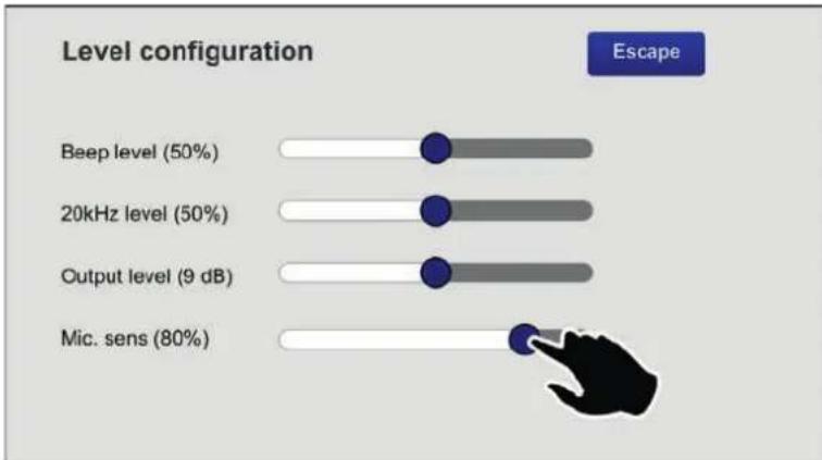
Zone key 1 configuration Escape Zone = 1 - Name = Zone 1 Up Zone num.: 1 Zone/Name edit Key 1 Key 2 Key 3 Key 4 Key 5 Key 6 Key 7 Key 8 Key 9 Key 10 Dn Save changes Z Zone 4 Back Q W E R T Y U I O P Canc A S D F G H J Z X C V B N M Numeric pad Uffici Vendite Zone 3 Zone 4 Zone 5 Configuration Zone 6 Zone 7 Zone 8 Zone 9 Zone 10 Zone 11 Zone 12 Zone 13 Zone 14 Zone 15 Zone 16 Zone 17 Zone 18 Zone 19 Zone 20 Zone 21 Zone 22 Zone 23 Zone 24 Zone 25 PTT F1 F2 F3 F4 F5 F64.3 Configurazione dei livelli (Level configuration)
Questa schermata consente la regolazione di livello dei seguenti parametri:
- Beep level Livello del buzzer di segnalazione guasti ("beep").
• 20kHz level Livello del tono di test.
• Output level Livello d'uscita (-7dB ÷ 24dB). - Mic. sens Livello della sensibilità del microfono (da ridurre in caso si presenti il cosiddetto "Effetto Larsen" per la vicinanza della postazione ai diffusori).
Spostare i cursori sulla barre fi no al raggiungimento dei livelli desiderati.
Premere 'Escape' per tornare alla schermata precedente.
bar
| Level configuration | Value | | ------------------- | ----- | | Beep level (50%) | 50% | | 20kHz level (50%) | 50% | | Output level (9 dB) | 9 dB | | Mic. sens (80%) | 80% |4.4 Configurazione del'unità (Unit configuration)
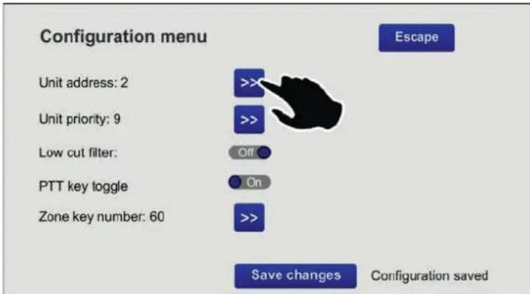
Questa schermata consente di impostare i principali parametri di funzionamento della postazione.
text_image
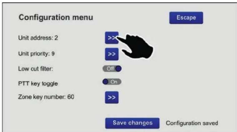
Configuration menu Unit address: 2 Unit priority: 9 Low cut filter: PTT key toggle Zone key number: 60 >>> >> Off On >> Save changes Configuration saved Escape4.4.1 Indirizzo (Unit address)
Ciascuna postazione dovrà avere un indirizzo univoco.
Premere il tasto >> per selezionare l'indirizzo desiderato.
Premere 'Save confagineare la selezione.
In caso non si vogliano salvare le modifiche, premere 'Escape'.
4.4.2 Priorità (Unit priority)
Per impostare la priorità della postazione, premere il tasto >> per selezionare il livello di priorità desiderato (i livelli a disposizione sono sette, da 8 = minima priorità a 14 = massima priorità).
NOTA: questo è un parametro molto importante, perché la priorità scelta determina l'operatività della postazione sia in stato d'emergenza che in condizione broadcast.
Premere 'Save changes' per confermare la selezione.
In caso non si vogliano salvare le modifi che, premere 'Escape'.
4.4.3 Filtro Low Cut (Low cut filter)
Per impostare il filtro low cut, agire sul cursore (On = filtro attivato; Off = filtro non attivato).
Premere 'Save changes' per confermare la selezione.
In caso non si voglia salvare la modifica, premere 'Escape'.
4.4.4 Modalità a ritenuta del tasto PTT (PTT Toggle)
Il tasto PTT per impostazione di fabbrica funziona come un pulsante, ovvero deve essere mantenuto premuto per essere attivo.
Tuttavia, in condizione broadcast, è possibile modificare questa caratteristica ed impostare che una volta premuto, rimanga in questo stato fino a successiva pressione.
Per fare ciò, è necessario spostare il cursore in posizione 'On'.
Nota: questa impostazione NON risulterà attiva in condizione d'emergenza.
Premere 'Save changes' per confermare la selezione.
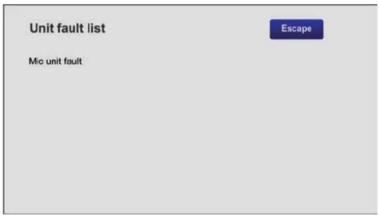
4.5 Lista guasti | Unit fault list
Questa schermata indica gli eventuali guasti occorsi alla postazione. Nell'esempio, viene segnalato un problema relativo al microfono della postazione.
text_image
Unit fault list Mic unit fault EscapeNota: su questa schermata viene anche segnalata l'eventuale mancanza di comunicazione seriale con l'unità di controllo a cui è collegata la postazione.
5. CARATTERISTICHE TECNICHE
| N° di zone selezionabili | 1 ÷ 216(da 20 a 60 tasti di selezione zone + 6 tasti funzione) |
| Livello d'uscita tipico | 300 mV |
| Risposta in frequenza | 20÷20.000 Hz |
| Distorsione | < 1% |
| Filtro LOW CUT | -10dB/100Hz |
| Rapporto S/N | >60 dB |
| Connessione | RJ45 (IN/OUT) |
| Tensione di alimentazione | 24 Vcc |
| Assorbimento massimo @24Vcc | 165 mA |
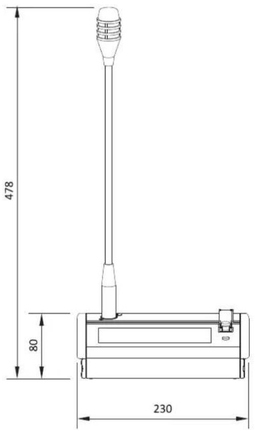
| Dimensioni (L x H x P) | 230 x 80 x 200 mm |
| Peso netto (senza microfono) | 1.61 kg |

text_image
478 80 230
natural_image
Technical line drawing of a mechanical lever or support structure with dimension标注 (no text or symbols present)pag.
GENERAL DESCRIPTION 18
CONNECTIONS 19
USE 22
SETTINGS & ADJUSTMENT 29
TECHNICAL SPECIFICATIONS 33
1. GENERAL DESCRIPTION
The TSC6000-EN touch-screen units for emergency calls enable hands-free messages and pre-recorded evacuation/alert messages to be sent out.
The large backlit display enables management and customisation of calls for every zone of the system, while specific LEDs provide the main information on the status of the emergency system and concerning any failures.
1.1 Numbered references
1) Socket for gooseneck or handheld microphone.
2) Status indicator LEDs.
3) Touch screen display.
4) Emergency button.
5) Reset button.
6) Connector for external 24 VDC power supply.
7) Input/output connectors.
text_image
1 2 3 FAULT POWER FBT Numeric pad Configuration Zone 1 Zone 2 Zone 3 Zone 4 Zone 5 Zone 6 Zone 7 Zone 8 Zone 9 Zone 10 Zone 11 Zone 12 Zone 13 Zone 14 Zone 15 Zone 16 Zone 17 Zone 18 Zone 19 Zone 20 Zone 21 Zone 22 Zone 23 Zone 24 Zone 25 PTT F1 F2 F3 F4 F5 F6 TSC6000-EN Emergency Unit EMERGENCY RESET/ACK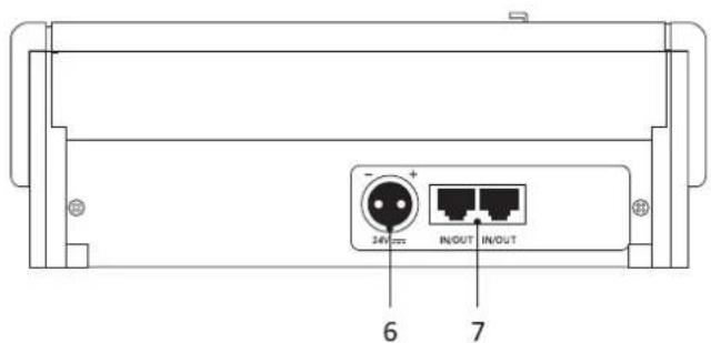
text_image
24V + - + IN/OUT IN/OUT 6 7Each station must be completed with an additional microphone (not included in the supply), to be chosen from among the following models:

FMG 2000
Dynamic gooseneck microphone

natural_image
Diagram of a solenoid connected to a device labeled FMH 2000 (no text or symbols on the diagram itself)Dynamic handheld microphone with PTT (push-to-talk) key
2. CONNECTIONS
The connections of the stations must be made using CAT. 5e SF/UTP cables with braided shields and shielded STP connectors.

text_image
Pin 1 1 2 3 4 5 6 7 8 Pin 8 Pin 8 8 7 6 5 4 3 2 1 Pin 1! N.B.:
Cross-cables are not permitted.
All the connectors must be shielded RJ45 connectors.
For these cables (and the associated RJ45 connectors), standards EIA/TIA T568A and EIA/TIA T568B call for the pinouts and colours indicated in the table. The pinouts of the IN/OUT connectors are also indicated (10).
| T568A | T568B | IN/OUT | |
| PIN | Colour | Colour | Colour |
| 1 | White/Green | White/Orange | Audio + |
| 2 | Green | Orange | Audio - |
| 3 | White/Orange | White/Green | GND |
| 4 | Blue | Blue | Not connected |
| 5 | White/Blue | White/Blue | Not connected |
| 6 | Orange | Green | +VDC |
| 7 | White/Brown | White/Brown | Serial + |
| 8 | Brown | Brown | Serial - |
| Shield | Shield | Shield | GND |
2.1 Connection to compact systems of the VAIE 6500 range
TSC6000-EN stations have to be connected to the 'EMG. DESK' socket of the compact VAIE 6500 system, and used as alternatives to the emergency systems of the FMD range. There can be at most 2 stations in each card-cage.
text_image
MAX 1 km TSC6000-EN TSC6000-EN #1 #2 MAX 2 UNITSCPU circuit
text_image
EMG. DESK DESK LINK LINK AUX MUSIC V3 d1 3V3 3V2 5V 5V AMP 1-2 CHARGER AMP 3-4 AMP 5-6 LED GND CONT. IN + - + - + - + - + - + - + - + - + - + - + - + - + - + - + - + - + - + - + - + - + - + - + - + - + - + - + - + - + - + - + - + - + - + - + - + - + - + - + - + - + - + - + - + - + - + - + - + - + - + - + -2.2 Connection to a VAC 2006 controller
TSC6000-EN stations have to be connected to the "EMERGENCY UNITS" socket (LINE A - compulsory setting) of the VAC 2006 controller, using a maximum of 7 units.
text_image
TSC6000-EN MAX 1 km LINE A MAX 4 UNITS FBT VAC 2006 I/O I/O I/O I/O I/O I/O I/O I/O I/O I/O I/O I/O I/O I/O I/O I/O I/O I/O I/O I/O I/O I/O I/O I/O I/O I/O I/O I/O I/O I/O I/O I/O I/O I/ON.B.:
If there are stations with keypads of the FMD range in a system managed by a controller, these stations must be connected to LINE B, as shown in the figure. In this configuration, the maximum number of stations that can be connected is 7.
text_image
MAX 1 km TSC6000-EN MAX 1 km MAX 7 TOTAL UNITS FMD2012 FMD2001 LINE A LINE B FDT VAC 2006 WIDE NUMBER CONTROLS CE HOT LANTERGENT, MELK CATHAN SPPS & MELDOS GAMES AND CONNECTIONS LPG LINE OUTPUT LPG LINE OUTPUT LPG LINE OUTPUT LPG LINE OUTPUT LPG LINE OUTPUT LPG LINE OUTPUT LPG LINE OUTPUT LPG LINE OUTPUT LPG LINE OUTPUT LPG LINE OUTPUT LPG LINE OUTPUT LPG LINE OUTPUT LPG LINE OUTPUT2.3 SIZING
The table below shows an example indicating the maximum total length limits that can be maintained for connections using CAT5e SF/UTP cables with braided shielding:
| No. of units | TSC6000/EN - VAIE 6500 TSC6000/EN - VAC 2006 |
| 1 300 m 300 m | |
| 2 200 m 200 m | |
| 3 100 m |
For systems calling for a higher number and/or distances longer than those indicated, each one of these microphone stations will also have to be powered locally with stabilised direct current at 24 VDC/500mA, using the socket provided for this purpose on the rear (6).
3. USE
Each TSC6000-EN station is equipped with a set of LEDs (2) for indicating the operating status of the system. The status corresponding to each LED is indicated below.
| ALARM | Red | This indicates a current “Alarm condition” in the system. | |
| FAULT SYS | Yellow | This signals the presence of a fault condition of the equipment to which the station is connected. | |
| FAULT UNIT | Yellow | This indicates an unspecified failure of the actual station. Consult the “Unit fault list” menu to see the type of failure (see point 4.5, Unit fault list, on page 33). | |
| DIS | Yellow | This signals an active “Disabled condition”. This indicates the presence of at least one zone in which the sending out of emergency messages is disabled. | |
| BUSY | Yellow | Off: system free (no station on calls).Steady ON: this indicates that another station having the same or a higher priority is occupying the system.Flashing: This indicates that another station with a lower priority is occupying the system. During a broadcast call, on the other hand, it indicates the length of the chime | |
| POWER LOC | Green | This indicates the presence of the local direct current supply applied to the external socket of the station | |
| POWER REM | Green | This indicates the presence of power supplied by a VAIE 6500 or by a VAC 2006 unit via the CAT 5 cable. |
N.B.:
For further information on the operating conditions of the system, such as the "Alarm status" or the "Disabled status", consult the section on "Operating conditions and names" of the manual of the control unit to which the system is connected.
All the zone selection, configuration and customisation operations are carried out via the station's touch screen display.
The main viewing mode is designated as the "KEY PAD" mode.
The same operations can also be carried out viewing the "NUMERIC PAD" (only in the broadcasting mode).
In this case the user can digit the zone number directly.
text_image
A B C D E Numeric pad Configuration PTT I H Zone 1 Zone 2 Zone 3 Zone 4 Zone 5 Zone 6 Zone 7 Zone 8 Zone 9 Zone 10 Zone 11 Zone 12 Zone 13 Zone 14 Zone 15 Zone 16 Zone 17 Zone 18 Zone 19 Zone 20 Zone 21 Zone 22 Zone 23 Zone 24 Zone 25 F1 F2 F3 F4 F5 F6 G FKEY PAD Mode
text_image
Key pad 1 2 3 4 5 6 7 8 9 0 Canc. Enter PTT F1 F2 F3 F4 F5 F6 Delete list L MNUMERIC PAD Mode
A. Key for changing to the NUMERIC PAD mode.
B. Configuration menu access key.
C. Zone-selection keypad.
D. Indicator showing the status of the hands-free call
• OFF: PTT not activated
• ON: PTT activated
E. Key for making hands-free calls (PTT).
F. Function keys.
G. Scroll bar.
H. Zone status indicator
I. Call type indicator
J. Key for changing to KEY PAD mode.
K. Numerical keypad.
L. List of selected zones.
M. Key for cancelling the list.
The TSC6000-EN station enables the following to be done via the system:
3.1 Sending out a service (broadcasting) call hands-free.
3.2 Sending out emergency messages hands-free.
3.3 Sending out pre-recorded evacuation /alert messages.
3.4 Sending out messages selectively to broadcasting zones.
3.5 Resetting emergency messages / Muting the buzzer to acknowledge a failure.
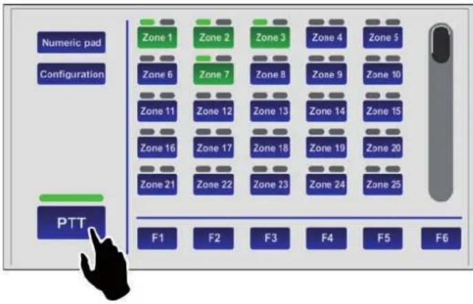
3.1 Sending out a service (broadcasting) call hands-free
To send out a service message hands-free to the broadcasting areas, press the PTT button (E) and hold it down. The green indicator will light up to show that the microphone is active.
Before speaking, remember to wait for the yellow BUSY LED to turn off, indicating the end of the chime. If no zone was selected in advance, the call will be sent to all the zones of the system, and therefore all the indicators (I) on the display will turn green.
text_image
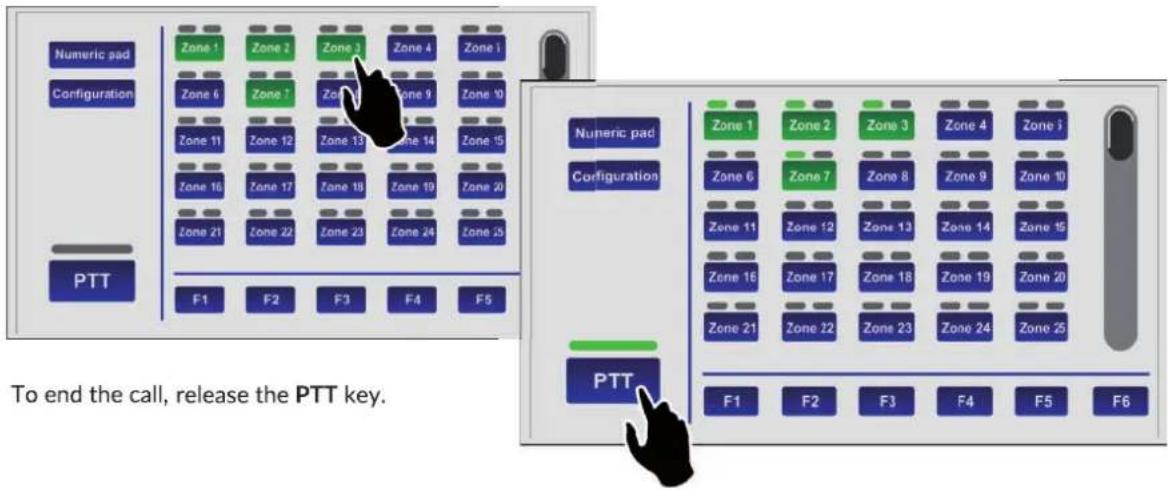
Numeric pad Configuration PTT Zone 1 Zone 2 Zone 3 Zone 4 Zone 5 Zone 6 Zone 7 Zone 8 Zone 9 Zone 10 Zone 11 Zone 12 Zone 13 Zone 14 Zone 15 Zone 16 Zone 17 Zone 18 Zone 19 Zone 20 Zone 21 Zone 22 Zone 23 Zone 24 Zone 25 F1 F2 F3 F4 F5 F6If you wish to address messages only to some zones or groups of zones, consult point 3.4 Sending out messages selectively to broadcasting zone (page 28).
text_image
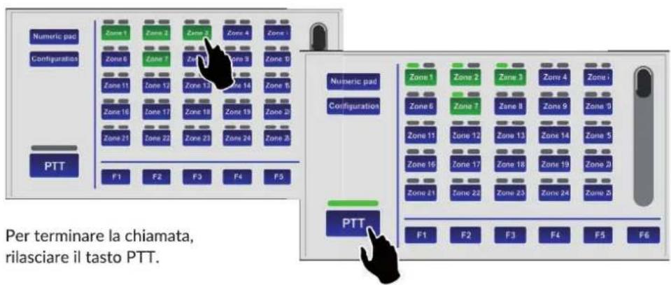
Numeric pad Configuration PTT Zone 1 Zone 2 Zone 3 Zone 4 Zone 1 Zone 6 Zone 7 Zone 8 Zone 9 Zone 10 Zone 11 Zone 12 Zone 13 Zone 14 Zone 15 Zone 16 Zone 17 Zone 18 Zone 19 Zone 20 Zone 21 Zone 22 Zone 23 Zone 24 Zone 25 F1 F2 F3 F4 F5 Numeric pad Configuration PTT Zone 1 Zone 2 Zone 3 Zone 4 Zone i Zone 6 Zone 7 Zone 8 Zone 9 Zone 10 Zone 11 Zone 12 Zone 13 Zone 14 Zone 15 Zone 16 Zone 17 Zone 18 Zone 19 Zone 20 Zone 21 Zone 22 Zone 23 Zone 24 Zone 25 F1 F2 F3 F4 F5 F6 To end the call, release the PTT key.3.2 Sending out emergency messages hands-free
To send out an emergency message hands-free to the broadcasting zones, it is necessary first of all the place the station in the emergency mode:
- Lift the lid protecting the EMERGENCY key (4) and press the key. It will light up steadily to indicate that the emergency mode has been activated. The background of the display will change colour and all the zone keys will turn green to indicate general pre-selection.

flowchart
graph TD
    A["EVAC"] --> B["Zone 1"]
    A --> C["Zone 2"]
    A --> D["Zone 3"]
    A --> E["Zone 4"]
    A --> F["Zone 5"]
    G["ALERT"] --> H["Zone 6"]
    G --> I["Zone 7"]
    G --> J["Zone 8"]
    G --> K["Zone 9"]
    G --> L["Zone 10"]
    M["PTT"] --> N["Zone 11"]
    M --> O["Zone 12"]
    M --> P["Zone 13"]
    M --> Q["Zone 14"]
    M --> R["Zone 15"]
    S["F1"] --> T["F2"]
    U["F3"] --> V["F4"]
    W["F5"] --> X["F6"]
    Y["EME"] --> Z["Hand Icon"]
- Press the PTT key and hold it down. The red ALARM LED will light up and the green indicator will show that it is possible to speak via the microphone. If no particular zones have been selected in advance, the message will be broadcast in all the zones. If you wish to address the message only to some specific zones or groups of zones, see point 3.4, Sending out messages to selected broadcasting zones (page 28).
N.B.: Remember that the PTT key has priority over any pre-recorded messages already being sent out.
flowchart
graph TD
    A["Zone 1"] --> B["Zone 2"]
    B --> C["Zone 3"]
    C --> D["Zone 4"]
    D --> E["Zone 5"]
    F["Zone 6"] --> G["Zone 7"]
    G --> H["Zone 8"]
    H --> I["Zone 9"]
    I --> J["Zone 10"]
    K["Zone 11"] --> L["Zone 12"]
    L --> M["Zone 13"]
    M --> N["Zone 14"]
    N --> O["Zone 15"]
    P["Zone 16"] --> Q["Zone 17"]
    Q --> R["Zone 18"]
    R --> S["Zone 19"]
    S --> T["Zone 20"]
    U["Zone 21"] --> V["Zone 22"]
    V --> W["Zone 23"]
    W --> X["Zone 24"]
    X --> Y["Zone 25"]
    Z["F1"] --> AA["F2"] --> AB["F3"] --> AC["F4"] --> AD["F5"] --> AE["F6"]
To end the hands-free emergency message, release the PTT key and press the EMERGENCY button again, remembering to close the lid.
NOTE: An emergency condition can be stopped only by a station with a higher priority or by local commands by the system (VAIE 6500 or VAC 2006).
The status of the EMERGENCY key indicates the condition of the system:
• OFF = emergency de-activated.
- Flashing = emergency under way, activated by another station or by local commands by the system.
- Steady ON = manual emergency activated from the station itself.
All the keys are active so as to enable the operator to manage the emergency.
3.3 Sending out pre-recorded evacuation/alert messages
To send out pre-recorded evacuation or alert messages (stored in the memory of the control unit connected to the TSC6000-EN), after activating the emergency mode (see point 3.2) press ALERT or EVAC to send out an alert or evacuation message respectively in the broadcasting zones.
flowchart
graph TD
    A["EVAC"] --> B["Zone 1"]
    A --> C["Zone 2"]
    A --> D["Zone 3"]
    A --> E["Zone 4"]
    A --> F["Zone 5"]
    G["ALER"] --> H["Zone 6"]
    G --> I["Zone 7"]
    G --> J["Zone 8"]
    G --> K["Zone 9"]
    G --> L["Zone 10"]
    M["PTT"] --> N["Zone 11"]
    M --> O["Zone 12"]
    M --> P["Zone 13"]
    M --> Q["Zone 14"]
    M --> R["Zone 15"]
    M --> S["Zone 16"]
    M --> T["Zone 17"]
    M --> U["Zone 18"]
    M --> V["Zone 19"]
    M --> W["Zone 20"]
    M --> X["Zone 21"]
    M --> Y["Zone 22"]
    M --> Z["Zone 23"]
    M --> AA["Zone 24"]
    M --> AB["Zone 25"]
    AC["F1"] --> AD["F2"]
    AE["F3"] --> AF["F4"]
    AG["F5"] --> AH["F6"]

The indicators (1) will turn red: if the evacuation message (EVAC) was selected they will remain steady ON. If the alert message (ALERT) was selected they will be fashing.
flowchart
graph TD
    A["PTT"] --> B["F1"]
    A --> C["F2"]
    A --> D["F3"]
    A --> E["F4"]
    A --> F["F5"]
    A --> G["F6"]
    H["EVAC"] --> I["Zone 1"]
    H --> J["Zone 2"]
    H --> K["Zone 3"]
    H --> L["Zone 4"]
    H --> M["Zone 5"]
    N["ALERT"] --> O["Zone 6"]
    N --> P["Zone 7"]
    N --> Q["Zone 8"]
    N --> R["Zone 9"]
    N --> S["Zone 10"]
    N --> T["Zone 11"]
    N --> U["Zone 12"]
    N --> V["Zone 13"]
    N --> W["Zone 14"]
    N --> X["Zone 15"]
    N --> Y["Zone 16"]
    N --> Z["Zone 17"]
    N --> AA["Zone 18"]
    N --> AB["Zone 19"]
    N --> AC["Zone 20"]
    N --> AD["Zone 21"]
    N --> AE["Zone 22"]
    N --> AF["Zone 23"]
    N --> AG["Zone 24"]
    N --> AH["Zone 25"]

Again in this case, if no particular zone was selected beforehand, the selected message will be sent out by default to all the zones. If you wish to send the message out only in some zones or groups of zones, consult point 3.4, Sending out messages to selected broadcasting zones (page 28).
To stop pre-recorded messages, hold the RESET/ACK button down until the messages are deactivated (about 2 seconds). By pressing the EMERGENCY button again, the messages will be deactivated and the station will exit the emergency mode. Remember to close the lid again.
3.4 Sending out messages selectively to broadcasting zones
The keypad of the TSC6000-EN station can be used to pre-select one or more zones to which to send out hands-free or pre-recorded messages. Each zone key has three indicators showing its condition:
| Indicator | Colour | System condition | Status | Meaning |
 | Red | Manual emergency activated | Steady ON, with ALARM LED ON | Pre-recorded evacuation announcement under way |
 | Red | Manual emergency activated | Flashing, with ALARM LED ON | Pre-recorded alert announcement under way |
 | Green | Idle condition | Steady | Hands-free service announcement under way |
 | Yellow | Fault condition | Flashing | Zone in failed condition or unavailable due to amplifier failure |
 | Yellow | Fault condition | Steady | Zone set in a “disabled condition” |
 | Green (key) | All | Steady | Zone selected |
3.4.1 Sending out messages selectively hands-free
After activating the emergency with the EMERGENCY key (all the keys turn green to indicate general pre-selection), press the buttons corresponding to the required zones. These will remain green to confirm that they have been selected.
At this point, press the PTT key and hold it down. The microphone will be activated and it will be possible to send out the announcement hands-free.
flowchart
graph TD
    subgraph EMERGENCY
        A["Zone 1"] --> B["Zone 2"]
        C["Zone 3"] --> D["Zone 4"]
        E["Zone 5"] --> F["Zone 6"]
        G["Zone 7"] --> H["Zone 9"]
        I["Zone 10"] --> J["Zone 11"]
        K["Zone 12"] --> L["Zone 13"]
        M["Zone 14"] --> N["Zone 15"]
        O["Zone 16"] --> P["Zone 17"]
        Q["Zone 18"] --> R["Zone 19"]
        S["Zone 20"] --> T["Zone 21"]
        U["Zone 22"] --> V["Zone 23"]
        W["Zone 24"] --> X["Zone 25"]
        Y["Zone 26"] --> Z["Zone 27"]
        AA["F1"] --> AB["F2"] --> AC["F3"] --> AD["F4"] --> AE["F5"] --> AF["F6"]
    end
    subgraph EMERGENCY
        AG["Zone 1"] --> AH["Zone 2"]
        AI["Zone 3"] --> AJ["Zone 4"]
        AK["Zone 5"] --> AL["Zone 6"]
        AM["Zone 7"] --> AN["Zone 8"]
        AO["Zone 9"] --> AP["Zone 10"]
        AQ["Zone 11"] --> AR["Zone 12"]
        AS["Zone 13"] --> AT["Zone 14"]
        AU["Zone 15"] --> AV["Zone 16"]
        AW["Zone 17"] --> AX["Zone 18"]
        AY["Zone 19"] --> AZ["Zone 20"]
        BA["Zone 21"] --> BB["Zone 22"]
        BC["Zone 23"] --> BD["Zone 24"]
        BE["Zone 25"] --> BF["Zone 26"]
        BG["F1"] --> BH["F2"] --> BI["F3"] --> BJ["F4"] --> BK["F5"] --> BL["F6"]
    end
    subgraph ALERT
        BM["PTT"] --> BN["PPTT"]
    end
At the end of the announcement, release the PTT key and press EMERGENCY again to exit the emergency mode.
3.4.2 Sending out pre-recorded evacuation or alerting messages selectively
After activating the emergency with the EMERGENCY key (all the keys turn green to indicate general pre-selection), press the buttons corresponding to the required zones. These will remain green to confirm that they have been selected. At this point:
• to send out an evacuation message, press EVAC.
• to send out an alert message, press ALERT.
It is possible to carry out the procedure described above several times to add more zones both in the ALERT and in the EVAC modes, keeping in mind that selection of EVAC for a zone has priority over selecting ALERT.
3.4.3 Sending out service messages hands-free
Select the required zones, which will turn green.
Press the PTT key and hold it down, waiting for the BUSY LED to turn OFF, indicating the end of the chime. At this point, the microphone is active and it is possible to send out the announcement hands-free. To end the announcement, release the PTT key.
3.4.4 Sending out messages selectively using the function keys
It is possible to send out messages or announcements to pre-selected groups of zones using the same procedures and sequences indicated above, with regard to both emergencies and service broadcasts. To this end, the station has 6 function keys (F1 to F6). To set the function keys, consult point 4.1, Function key configuration (page 30).
3.5 Resetting emergency messages / Muting the buzzer to acknowledge a failure
The RESET/ACK key (5) has different functions depending on the status of the system:
RESET function | Resetting messages
While there is an alarm condition in progress or with a station in the emergency condition, keeping the RESET/ACK key pressed for 2 seconds enables sending out of the messages to be stopped (including those called up by activation of the control inputs), but keeping in any case the system in a condition of emergency.
ACK function | Muting of the buzzer to acknowledge a failure
In the presence of failures, press the RESET/ACK key briefly. The buzzer will be muted only on the station, while the LED referred to the failure under way will remain ON.
This function is active in any status of the station (emergency or service).
In the event of a new additional failure, the buzzer will start to sound again.
4. SETTINGS AND ADJUSTMENT
By pressing the 'Configuration' (B) while viewing the Keypad, it is possible to access the configuration menu of the TSC6000-EN. To return to the main screen, press 'Escape'.
text_image
Configuration menu Function key configuration >> Zone key configuration >> Level configuration >> Unit configuration >> Unit fault list >> Escape Firmware: vers. 1, rel. 04.1 Function key configuration
This screen page enables the broadcasting zones to be associated with the function keys from F1 to F6. Using this option, it will be possible to send messages to a pre-selected group of zones pressing a single key.
N.B.: Each key is factory set to call all the zones (green). It is possible, using the "Reset all zones" key, to change this setting by clicking only once (the zones that are not associated will be red).
text_image
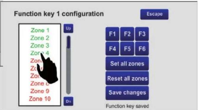
Function key 1 configuration Zone 1 Zone 2 Zone 3 Zone 4 Zone 5 Zone 6 Zone 7 Zone 8 Zone 9 Zone 10 Up Dn Escape F1 F2 F3 F4 F5 F6 Set zones Reset all zones Save changes Function key savedStarting out from this condition, it is possible, for example, to configure key F1 :
- Press F1: The wording "Function key 1 con figuration" will appear above the list to confirm the selection made.
text_image
Function key 1 configuration Zone 1 Zone 2 Zone 3 Zone 4 Zone 5 Zone 6 Zone 7 Zone 8 Zone 9 Zone 10 Up On Escape F1 F2 F3 F4 F5 F6 Set all zones Reset all zones Save changes Function key saved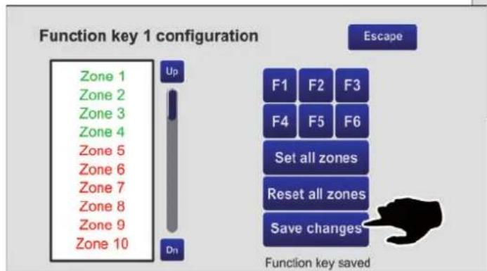
text_image
Function key 1 configuration Zone 1 Zone 2 Zone 3 Zone 4 Zone 5 Zone 6 Zone 7 Zone 8 Zone 9 Zone 10 Up Dn Escape F1 F2 F3 F4 F5 F6 Set all zones Reset all zones Save changes Function key saved- Use the 'U p' and 'Dn' keys to browse through the list and select the zones to be associated with the key (in the example, 1, 2, 3 and 4).
- Press 'Save changes', then 'Escape' to return to the configuration menu.
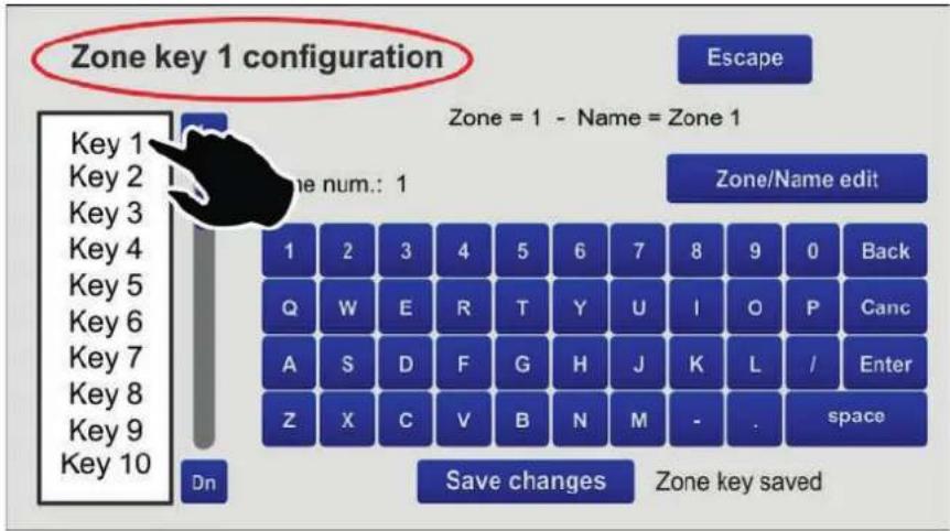
4.2 Zone key configuration
This screen page enables the 60 available keys to be configured separately and to customise their names. By way of example, try configuring key no. 1 as associated with zone 1 and identify it as 'Uffici'.

text_image
Zone key 1 configuration Escape Zone = 1 - Name = Zone 1 Zone num.: 1 Zone/Name edit 1 2 3 4 5 6 7 8 9 0 Back Q W E R T Y U I O P Canc A S D F G H J K L / Enter Z X C V B N M -. space Dn Save changes Zone key saved- Select the item 'Key1' from the list of keys: the wording "Zone key1 configuration" will appear on the screen, showing that key no. 1 is being dealt with.
- Press the 'Zone/name edit' key, then the '1' key: the wording "Zone num.: 1" will appear. Press 'Enter' to confirm.
- Press the 'Zone/Name edit' key again and digit 'uffici': the wording "Zone name: "uffici" will appear. Press 'Enter' to confirm.
- Press 'Save changes' to save the configuration. Continue in the same manner for the other keys.
text_image
Zone key 1 configuration Escape Zone = 1 - Name = Zone 1 Up Zone num.: 1 Zone/Name edit Key 1 Key 2 Key 3 Key 4 Key 5 Key 6 Key 7 Key 8 Key 9 Key 10 Dn Save changes Zone 3 Zone/Name edit 1 2 3 4 5 6 7 8 9 0 Back Q W E R T Y U I O P Canc A S D F G H J Z X C V B N M Numeric pad Uffici Vendite Zone 3 Zone 4 Zone 5 Configuration Zone 6 Zone 7 Zone 8 Zone 9 Zone 10 Zone 11 Zone 12 Zone 13 Zone 14 Zone 15 Zone 16 Zone 17 Zone 18 Zone 19 Zone 20 Zone 21 Zone 22 Zone 23 Zone 24 Zone 25 PTT F1 F2 F3 F4 F5 F64.3 Level configuration
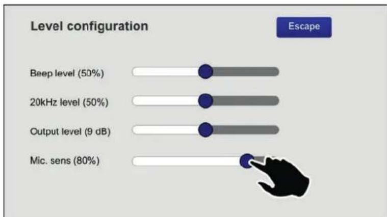
This screen page can be used to adjust the levels of the following parameters:
- Beep level Volume of the failure signalling buzzer (beep).
• 20kHz level Volume of the test tone.
• Output level -7dB to 24dB. - Mic. sens Level of sensitivity of the microphone (to be lowered in the event of a so-called "Larsen effect" due to closeness of the station to the speakers).
Move the cursors along the bar until the required level is reached.
Press 'Escape' to return to the previous screen page.
bar
| Level | Percentage | |-------|----------| | Beep level | 50% | | 20kHz level | 50% | | Output level | 9 dB | | Mic. sens | 80% |4.4 Unit configuration
This screen page enables the main operating parameters of the station to be set.
text_image
Configuration menu Unit address: 2 Unit priority: 9 Low cut filter: PTT key toggle Zone key number: 60 >>> >>> Off On >>> Save changes Escape Configuration saved4.4.1 Unit address
Each station must have its own univocal address.
Press the >> key to select the desired address.
Press 'Save changes' to confirm the selection made.
If you do not wish to save the changes made, press 'Escape
4.4.2 Unit priority
To set the priority level of the station, press the >> key to select the desired level of priority (there are seven possible levels, from 8 = lowest priority to 14 = top priority).
NOTE: This is a very important parameter as the priority that is chosen determines the operating conditions of the station both in an emergency condition and in a broadcasting condition.
Press 'Save changes' to confirm the selection made. If you do not wish to save the changes, press 'Escape'.
4.4.3 Low-Cut Filter
To set the low-cut filter, use the cursor (ON = filter activated, OFF = filter not activated). Press 'Save changes' to confirm the selection mode. If you do not wish to save the change, press 'Escape'.
4.4.4 PTT Toggle
The PTT button is factory set to work as a toggle button, that is to say, in order to be active it has to be pressed and then held down. In a broadcasting condition, however, it is possible to change this feature and set the button so that once it is pressed it will remain down until it is pressed again.
To do this, the cursor has to be moved to its 'ON' position.
N.B.: This setting will NOT be active in emergency conditions.
Press 'Save changes' to confirm the selection.
4.5 Unit fault list
This screen shows any failures that have occurred to the station. In the example, a problem concerning the station's microphone is indicated.

text_image
Unit fault list Mic unit fault EscapeNote: The lack, if any, of serial communication with the control unit to which the station is connected is also signalled on this page.
5. TECHNICAL SPECIFICATIONS
| No. of zones that can be selected | 1 to 216(from 20 to 60 zone selection keys plus 6 function keys) |
| Typical output level | 300 mV |
| Frequency response | 20÷20.000 Hz |
| Distortion | < 1% |
| LOW-CUT Filter | -10dB/100Hz |
| S/N Ratio | >60 dB |
| Connection | RJ45 (IN/OUT) |
| Power supply voltage | 24 Vcc |
| Maximum absorption @24VDC | 165 mA |
| Size (L x H x P) | 230 x 80 x 200 mm |
| Net weight (without microphone) | 1.61 kg |
text_image
478 80 230
natural_image
Technical line drawing of a mechanical lever or support structure with dimension标注 (no text or symbols present)
(1) 2017年,公司与关联方发生的交易金额为人民币4,000万元,占公司最近一期经审计净资产的5%;
The Ground Truth image displays a single, solid horizontal line, which is a stylistic or background element (like a rule line on paper). According to Rule 2, such lines must be ignored by the OCR result. The provided OCR content is "____", which consists of underscores. Underscores are not equivalent to a solid line and are not permitted under the “Stylistic/Background Lines (Ignore)” rule. Outputting underscores for a stylistic line is incorrect because it misinterprets the line as a fill-in-the-blank placeholder. Since the OCR output incorrectly rendered a stylistic line as underscores (which should be ignored), this violates the rule. Therefore, the OCR result is inconsistent with the Ground Truth.
The Ground Truth image displays a single, solid horizontal line. According to Rule 2 (UNDERSCORE & LINE RULES), this is a stylistic or background line, not a placeholder underscore. Therefore, the OCR result must ignore it and output nothing or only meaningful text. The provided OCR content is "____", which consists of four underscores. This is an incorrect interpretation of the line as a placeholder, violating the rule that stylistic lines must be ignored. The OCR has hallucinated placeholder underscores where none should exist in the GT. This adheres to the strict requirement to ignore such lines.
(1) 12 (2) 12 (3) 12 (4) 12 (5) 12 (6) 12 (7) 12 (8) 12 (9) 12 (10) 12 (11) 12 (12) 12 (13) 12 (14) 12 (15) 12 (16) 12 (17) 12 (18) 12 (19) 12 (20)
本公司于2015年4月29日向中国证券登记结算有限责任公司深圳分公司(以下简称“公司”)申请的首次公开发行股票并在科创板上市之日起36个月内,不转让或者委托他人管理本次发行前已持有的公司股份。本次发行完成后,本公司将不会在中国境内以任何方式(包括但不限于单独经营、通过合资经营或拥有另一公司或企业的股份)直接或间接从事与发行人相同或相似业务的业务活动。
Theorem 1.2. (A) Let (R) be a finite field and let (x) be the set of all elements of such that x (x) . Then
The OCR result should be empty, as the source image contains only a stylistic horizontal line that must be ignored according to Rule 2. No text or placeholder characters should be output.
(No text)
(1) 12 (2) 12 (3) 12 (4) 12 (5) 12 (6) 12 (7) 12 (8) 12 (9) 12 (10) 12 (11) 12 (12) 12 (13) 12 (14) 12 (15) 12 (16) 12 (17) 12 (18) 12 (19) 12 (20)
[Non-Text]
(1) 2017年,公司与上海浦东发展银行股份有限公司签订了《关于使用部分闲置募集资金进行现金管理的协议》。公司独立董事发表了独立意见,同意公司使用不超过人民币3,000万元的闲置募集资金进行现金管理。
The Ground Truth image displays a single, solid horizontal line. According to Rule 2 (UNDERSCORE & LINE RULES), this is a stylistic or background line, not a placeholder underscore. Therefore, the OCR result must ignore it. The provided OCR content is "____", which consists of four underscores. This is an incorrect interpretation of the line as a placeholder, violating the rule that stylistic lines must be ignored. The OCR has hallucinated text (underscores) where none should exist, violating the rule to ignore such lines. Hence, the OCR result is inconsistent with the Ground Truth.
[Non-Text]
The OCR result should be empty, as the source image contains only a stylistic horizontal line that must be ignored according to Rule 2. No text or placeholder characters should be output.
(1) 2017年,公司与上海浦东发展银行股份有限公司签订了《关于使用部分闲置募集资金进行现金管理的协议》。公司独立董事发表了独立意见,同意公司使用不超过人民币3,000万元的闲置募集资金进行现金管理,使用期限自董事会审议通过之日起不超过三年。
The following table provides the information in three different categories: (1) a general description of the subject, and (2) a reference to the subject. The other section contains an additional reference to the subject.
The Ground Truth image displays a single, solid horizontal line, which is a stylistic or background element (like a rule line on paper). According to Rule 2, such lines must be ignored by the OCR result. The provided OCR content is "____", which consists of underscores. Underscores are not equivalent to a solid line and are not permitted under the “Stylistic/Background Lines (Ignore)” rule. Outputting underscores for a stylistic line is incorrect because it misinterprets the line as a fill-in-the-blank placeholder. Since the OCR output incorrectly rendered a stylistic line as underscores (which should be ignored), this violates the rule. Therefore, the OCR result is inconsistent with the Ground Truth.
The Ground Truth image displays a single, solid horizontal line. According to Rule 2 (UNDERSCORE & LINE RULES), this is a stylistic or background line, not a placeholder underscore. Therefore, the OCR result must ignore it and output nothing or only meaningful text. The provided OCR content is "____", which consists of four underscores. This is an incorrect interpretation of the line as a placeholder, violating the rule that stylistic lines must be ignored. The OCR has hallucinated placeholder underscores where none exist in the GT. Hence, the OCR result is inconsistent with the Ground Truth.
The Ground Truth image displays a single, solid horizontal line, which is a stylistic or background element (like a rule line on paper). According to Rule 2, such lines must be ignored by the OCR result. The OCR content provided is "", which consists of no characters. Since the OCR output correctly ignores the stylistic line, it complies with Rule 2. Therefore, the OCR result is consistent with the Ground Truth.
(1) 本报告书的摘要、报告内容及正文(包括但不限于全文、电子版、合同等)都是真实的,不存在任何虚假记载、误导性陈述或者重大遗漏。
Theorem 1.2. (A) Let () be a finite field and let (x) be the set of all elements of () such that x (x) . Then
The Ground Truth image displays a single, solid horizontal line, which is a stylistic or background element (like a rule line on paper). According to Rule 2, such lines must be ignored by the OCR result. The OCR content provided is "", which consists of no characters. Since the OCR output correctly ignores the stylistic line, it complies with Rule 2. Therefore, the OCR result is consistent with the Ground Truth.
(1) AD = BD = 1
(1) ^2 = ^2 = ^2 = ^2 = ^2 = ^2 = ^2 = ^2 = ^2 = ^2
[Non-Text]
Theorem 1.2. (A) Let () be a finite field and let (0) be the set of all elements of such that (0) (0) . Then
(1) 本报告期,公司及子公司、参股企业不存在以自有资金从事与公司主营业务构成或可能构成竞争的业务活动,亦不会在中国境内以任何形式直接或间接从事与公司主营业务构成或可能构成竞争的业务活动。公司董事会及全体董事保证本报告期无任何违反《中华人民共和国公司法》、《中华人民共和国证券法》、《上市公司治理准则》等法律、法规和规范性文件的规定,且不构成对公司的重大经营决策、重大投资计划、重大财务资助、重大关联交易、重大对外担保、重大关联交易、重大投资计划、重大对外投资、重大投资计划、重大对外投资、重大投资计划、重大对外投资、重大投资计划、重大对外投资、重大投资计划、重大对外投资、重大投资计划、重大对外投资、重大投资计划、重大对外投资、重大投资计划、重大对外投资、重大投资计划、重大对外投资、重大投资计划、重大对外投资、重大投资计划、重大对外投资、重大投资计划、重大对外投资、重大投资计划、重大对外投资、重大投资
(1) 2017年,公司与上海浦东发展银行股份有限公司签订了《关于使用部分闲置募集资金进行现金管理的协议》。
The following table provides the information in the context of the research and development of the research and development of the research and development of the research and development of the research and development of the research and development of the research and development of the research and development of the research and development of the research and development of the research and development of the research and development of the research and development of the research and development of the research and development of the research and development of the research and development of the research and development of the research and development of the research and development of the research and
公司及控股子公司拟以现金方式向控股股东中国银行股份有限公司深圳分行申请的综合授信额度不超过人民币10亿元,其中担保金额为人民币30亿元。
The Ground Truth image displays a single, solid horizontal line. According to Rule 2 (UNDERSCORE & LINE RULES), this is a stylistic or background line, not a placeholder underscore. Therefore, the OCR result must ignore it. The provided OCR content is "____", which consists of four underscores. This is an incorrect interpretation of the line as a placeholder, violating the rule that stylistic lines must be ignored. The OCR has hallucinated text (underscores) where none should exist. Hence, the result is inconsistent with the Ground Truth.
The Ground Truth image displays a single, solid horizontal line. According to Rule 2 (UNDERSCORE & LINE RULES), this is a stylistic or background line, not a placeholder underscore. Therefore, the OCR result must ignore it and output nothing or only meaningful text. The provided OCR content is "____", which consists of four underscores. This is an incorrect interpretation of the line as a fill-in-the-blank placeholder, violating the rule that stylistic lines must be ignored. The OCR has hallucinated underscores where none should exist based on the GT's visual context. Hence, the OCR result is inconsistent with the Ground Truth.
The Ground Truth image displays a single, solid horizontal line. According to Rule 2 (UNDERSCORE & LINE RULES), this is a stylistic or background line, not a placeholder underscore. Therefore, the OCR result must ignore it. The provided OCR content is "____", which consists of four underscores. This is an incorrect interpretation of the line as a placeholder and violates the rule that stylistic lines must be ignored. The OCR has hallucinated text (underscores) where none should exist, violating the rule to ignore stylistic lines. Hence, the OCR result is inconsistent with the Ground Truth.
- 2014年1月1日,公司召开2014年第一次临时股东大会,审议通过了《关于使用部分闲置募集资金进行现金管理的议案》,同意公司使用不超过人民币3,000万元的闲置募集资金进行现金管理。
[Non-Text]
The following table provides the basic information and the content of a specific character:
The Ground Truth image displays a single, solid horizontal line. According to Rule 2 (UNDERSCORE & LINE RULES), if the GT contains lines used for stylistic emphasis or as background elements (like ruled paper), the OCR result must ignore them. The line in the GT is clearly a stylistic/background line, not a placeholder for text. Therefore, the OCR should not have output any underscores. Outputting `____` constitutes an error under Rule 2, as it hallucinates placeholder symbols where none are semantically intended. Hence, the OCR result is inconsistent with the Ground Truth.
(No text)
The OCR result should be empty, as the source image contains only a stylistic horizontal line which must be ignored according to Rule 2. No text or placeholder characters should be output.
[Non-Text]
Theorem 1.2. (A) Let () be a finite field and let (x) be the set of all elements of such that x (x) . Then
The Ground Truth image displays a single, solid horizontal line. According to Rule 2 (UNDERSCORE & LINE RULES), this is a stylistic or background line, not a placeholder underscore. Therefore, the OCR result must ignore it and output nothing or only meaningful text. The provided OCR content is "____", which consists of four underscores. This is an incorrect interpretation of the line as a placeholder, violating the rule that stylistic lines must be ignored. The OCR has hallucinated placeholder underscores where none should exist in the GT. Hence, the OCR result is inconsistent with the Ground Truth.
本公司及董事会全体成员保证信息披露的内容真实、准确、完整,没有虚假记载、误导性陈述或重大遗漏,并对其内容的真实性、准确性和完整性承担个别及连带责任。
The OCR result should be empty, as the source image contains only a stylistic horizontal line that must be ignored according to Rule 2. No text or placeholder characters should be output.
本公司于2014年1月1日召开的2014年第三次临时股东大会,审议通过了《关于公司符合非公开发行股票条件的议案》,同意公司本次非公开发行股票的发行价格为人民币1.50元/股,每股面值为人民币1.50元。
The OCR result should be empty, as the image contains only a stylistic horizontal line which must be ignored according to Rule 2. No text or placeholder characters should be output.
(No text)
(1) 2017年,公司与上海浦东发展银行股份有限公司签订了《关于使用部分闲置募集资金进行现金管理的协议》。
(1) 12 (2) 12 (3) 12 (4) 12 (5) 12 (6) 12 (7) 12 (8) 12 (9) 12 (10) 12 (11) 12 (12) 12 (13) 12 (14) 12 (15) 12 (16) 12 (17) 12 (18) 12 (19) 12 (20)
The Ground Truth image displays a single, solid horizontal line. According to Rule 2 (UNDERSCORE & LINE RULES), this is a stylistic or background line, not a placeholder underscore. Therefore, the OCR result must ignore it and output nothing or only meaningful text. The provided OCR content is "____", which consists of four underscores. This is an incorrect interpretation of the line as a placeholder, violating the rule that stylistic lines must be ignored. The OCR has hallucinated placeholder underscores where none should exist in the GT. Hence, the OCR result is inconsistent with the Ground Truth.
(1) AD = AC = B^ (2) BC = DC = F^ (3) AD = AC = B^
The Ground Truth image displays a single, solid horizontal line. According to Rule 2 (UNDERSCORE & LINE RULES), this is a stylistic or background line, not a placeholder underscore. Therefore, the OCR result must ignore it and output nothing or only meaningful text.
(no text)
(1) 2017年,公司与关联方发生的交易金额为人民币4,500万元,占公司最近一期经审计净资产的10%;
The OCR result should be empty, as the source image contains only a stylistic horizontal line that must be ignored according to Rule 2. No text or placeholder characters should be output.
(1) AD = BD = 1
The following table provides the original data for each of the four categories: (1) the first category, (2) the second, and (3) the third. The values of the first category are calculated as 12 . The second category is calculated as 12 . The third category is calculated as 12 .
(1)基因通过控制 通过控制____,____的合成来控制代谢过程,进而控制生物体的性状。
本公司及本公司全体成员保证信息披露的内容真实、准确、完整,没有虚假记载、误导性陈述或重大遗漏,并对其内容的真实性、准确性和完整性承担个别及连带责任。
[Non-Text]
[Non-Text]
[Non-Text]
[EMPTY]

FBT ELETTRONICA SPA
Via Paolo Soprani 1 - 62019 RECANATI - ITaly
Tel. 071750591 - Fax. 071 7505920
emai: info@fbt.it - www.fbt.it
Le informazioni contenute in questo manuale sono state scrupolosamente controllate; tuttavia FBT non si assume nessuna responsabilità per eventuali inesattezze. La FBT Elettronica S.p.A. si riserva il diritto di modificare le caratteristiche tecniche ed estetiche dei prodotti in qualsiasi momento e senza preavviso.
All information included in this operating manual have been scrupulously controlled; however FBT is not responsible for eventual mistakes. FBT Elettronica S.p.A. has the right to amend products and specifications without notice.