DMB160 - Éclairage Futurelight - Notice d'utilisation et mode d'emploi gratuit
Retrouvez gratuitement la notice de l'appareil DMB160 Futurelight au format PDF.

| Caractéristiques Techniques | Projecteur LED à effet lumière, puissance de 160W, température de couleur de 6000K, flux lumineux de 12000 lumens. |
|---|---|
| Utilisation | Idéal pour les événements en direct, les concerts, les clubs et les installations scéniques. |
| Maintenance et Réparation | Nettoyage régulier des lentilles et des ventilateurs recommandé, vérification des connexions électriques avant chaque utilisation. |
| Sécurité | Utiliser uniquement dans des environnements appropriés, éviter l'exposition à l'eau, respecter les instructions de montage. |
| Informations Générales | Garantie de 2 ans, poids de 5 kg, dimensions de 30 x 20 x 15 cm, compatible avec les systèmes DMX. |
FOIRE AUX QUESTIONS - DMB160 Futurelight
Questions des utilisateurs sur DMB160 Futurelight
0 question sur cet appareil. Repondez a celles que vous connaissez ou posez la votre.
Poser une nouvelle question sur cet appareil
Téléchargez la notice de votre Éclairage au format PDF gratuitement ! Retrouvez votre notice DMB160 - Futurelight et reprennez votre appareil électronique en main. Sur cette page sont publiés tous les documents nécessaires à l'utilisation de votre appareil DMB160 de la marque Futurelight.
MODE D'EMPLOI DMB160 Futurelight
Futurelight®
BEDIENUNGSANLEITUNG USER MANUAL
DMB-160 LED Moving Head
natural_image
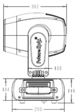
Technical line drawing of a mechanical component with top and side views (no text or symbols)Inhaltsverzeichnis
Deutsch
EINFÜHRUNG......4
Lieferumfang 4
SICHERHEITSHINWEISE....5
BESTIMMUNGSGEMÄße VERWENDUNG......6
GERÄTEBESCHREIBUNG 8
Features 8
Geräteübersicht....9
INSTALLATION 10
Projektormontage....10
Einbau des optionalen drahtlos-Empfängers für WDMX-Betrieb (FUTURELIGHT WDR-G4).... 13
Anschluss an den DMX-512 Controller / Verbindung Projektor – Projektor 14
Anschluss ans Netz.... 15
BEDIENUNG 15
Standalone-Betrieb 15
DMX-gesteuerter Betrieb 15
Adressierung des Projektors 15
DMX-Protokoll 16
Control Board 23
Connect....24
Light 25
Information 25
Set 25
Program 27
Fehlermeldungen 29
REINIGUNG UND WARTUNG.... 30
Sicherungswechsel 30
TECHNISCHE DATEN 31
KONFORMITAT 32
Table of contents
English
INTRODUCTION 33
Delivery includes 33
SAFETY INSTRUCTIONS 33
OPERATING DETERMINATIONS.... 35
DESCRIPTION OF THE DEVICE 36
Features 36
Overview 37
INSTALLATION 38
Rigging 38
Installation of the optional wireless receiver for WDMX-operation (FUTURELIGHT WDR-G4).... 41
DMX-512 connection / connection between fixtures 42
Connection with the mains 43
OPERATION 43
Stand Alone operation 43
DMX-controlled operation 43
Addressing 43
DMX-protocol 44
Control Board 51
Connect....52
Light 53
Information 53
Set....53
Program 55
Error Messages....57
CLEANING AND MAINTENANCE 58
Replacing the fuse 58
TECHNICAL SPECIFICATIONS....59
Diese Bedienungsanleitung gilt für die Artikelnummer: / This user manual is valid for the article number: 51841807
Das neueste Update dieser Bedienungsanleitung finden Sie im Internet unter:
You can find the latest update of this user manual in the Internet under:
www.futurelight.com
BEDIENUNGSANLEITUNG
Futurelight®
DMB-160 LED-Moving-Head

ACHTUNG!
Gerät vor Feuchtigkeit und Nässe schützen!
Niemals das Gerät öffnen!
Lesen Sie vor der ersten Inbetriebnahme zur eigenen Sicherheit diese Bedienungsanleitung sorgfältig durch!
Alle Personen, die mit der Aufstellung, Inbetriebnahme, Bedienung, Wartung und Instandhaltung dieses Gerätes zu tun haben, müssen
- entsprechend qualifiziert sein
- diese Bedienungsanleitung genau beachten
- die Bedienungsanleitung als Teil des Produkts betrachten
- die Bedienungsanleitung während der Lebensdauer des Produkts behalten
- die Bedienungsanleitung an jeden nachfolgenden Besitzer oder Benutzer des Produkts weitergeben
- sich die letzte Version der Anleitung im Internet herunter laden
EINFÜHRUNG
Wir freuen uns, dass Sie sich für einen FUTURELIGHT DMB-160 entschieden haben. Sie haben hiermit ein leistungsstarkes und vielseitiges Gerät erworben.
Nehmen Sie den DMB-160 aus der Verpackung.
Lieferumfang
| Gerät |
| Bedienungsanleitung |
| Omega Halter mit Schnellverschluss |
| DMX-Kabel 3 m |
| PowerCon Netzkabel 1,5 m |
SICHERHEITSHINWEISE
ACHTUNG!
Seien Sie besonders vorsichtig beim Umgang mit gefährlicher Netzspannung. Bei dieser Spannung können Sie einen lebensgefährlichen elektrischen Schlag erhalten!
Dieses Gerät hat das Werk in sicherheitstechnisch einwandfreiem Zustand verlassen. Um diesen Zustand zu erhalten und einen gefahrlosen Betrieb sicherzustellen, muss der Anwender die Sicherheitshinweise und die Warnvermerke unbedingt beachten, die in dieser Bedienungsanleitung enthalten sind.

Unbedingt lesen:
Bei Schäden, die durch Nichtbeachtung der Anleitung verursacht werden, erlischt der Garantieanspruch. Für daraus resultierende Folgeschäden übernimmt der Hersteller keine Haftung.
Das Gerät darf nicht in Betrieb genommen werden, nachdem es von einem kalten in einen warmen Raum gebracht wurde. Das dabei entstehende Kondenswasser kann unter Umständen Ihr Gerät zerstören. Lassen Sie das Gerät solange uneingeschaltet, bis es Zimmertemperatur erreicht hat!
Bitte überprüfen Sie vor der ersten Inbetriebnahme, ob kein offensichtlicher Transportschaden vorliegt. Sollten Sie Schäden an der Netzleitung oder am Gehäuse entdecken, nehmen Sie das Gerät nicht in Betrieb und setzen sich bitte mit Ihrem Fachhändler in Verbindung.
Der Aufbau entspricht der Schutzklasse I. Der Netzstecker darf nur an eine Schutzkontakt-Steckdose angeschlossen werden, deren Spannung und Frequenz mit dem Typenschild des Gerätes genau übereinstimmt. Ungeeignete Spannungen und ungeeignete Steckdosen können zur Zerstörung des Gerätes und zu tödlichen Stromschlägen führen.
Den Netzstecker immer als letztes einstecken. Der Netzstecker muss dabei gewaltfrei eingesetzt werden. Achten Sie auf einen festen Sitz des Netzsteckers.
Lassen Sie die Netzleitung nicht mit anderen Kabeln in Kontakt kommen! Seien Sie vorsichtig beim Umgang mit Netzleitungen und -anschlüssen. Fassen Sie diese Teile nie mit feuchten Händen an! Feuchte Hände können tödliche Stromschläge zur Folge haben.
Netzleitungen nicht verändern, knicken, mechanisch belasten, durch Druck belasten, ziehen, erhitzen und nicht in die Nähe von Hitze- oder Kältequellen bringen. Bei Missachtung kann es zu Beschädigungen der Netzleitung, zu Brand oder zu tödlichen Stromschlägen kommen.
Die Kabeleinführung oder die Kupplung am Gerät dürfen nicht durch Zug belastet werden. Es muss stets eine ausreichende Kabellänge zum Gerät hin vorhanden sein. Andernfalls kann das Kabel beschädigt werden, was zu tödlichen Stromschlägen führen kann.
Achten Sie darauf, dass die Netzleitung nicht gequetscht oder durch scharfe Kanten beschädigt werden kann. Überprüfen Sie das Gerät und die Netzleitung in regelmäßigen Abständen auf Beschädigungen.
Werden Verlängerungsleitungen verwendet muss sichergestellt werden, dass der Adernquerschnitt für die benötigte Stromzufuhr des Gerätes zugelassen ist. Alle Warnhinweise für die Netzleitung gelten auch für evtl. Verlängerungsleitungen.
Gerät bei Nichtbenutzung und vor jeder Reinigung vom Netz trennen! Fassen Sie dazu den Netzstecker an der Grifffläche an und ziehen Sie niemals an der Netzleitung! Ansonsten kann das Kabel und der Stecker beschädigt werden was zu tödlichen Stromschlägen führen kann. Sind Stecker oder Geräteschalter, z. B. durch Einbau nicht erreichbar, so muss netzseitig eine allpolige Abschaltung vorgenommen werden.
Wenn der Netzstecker oder das Gerät staubig ist, dann muss es außer Betrieb genommen werden, der Stromkreis muss allpolig unterbrochen werden und das Gerät mit einem trockenen Tuch gereinigt werden. Staub kann die Isolation reduzieren, was zu tödlichen Stromschlägen führen kann. Stärkere Verschmutzungen im und am Gerät dürfen nur von einem Fachmann beseitigt werden.
Deutsch
Es dürfen unter keinen Umständen Flüssigkeiten aller Art in Steckdosen, Steckverbindungen oder in irgendwelche Geräteöffnungen oder Geräteritzen eindringen. Besteht der Verdacht, dass - auch nur minimale - Flüssigkeit in das Gerät eingedrungen sein könnte, muss das Gerät sofort allpolig vom Netz getrennt werden. Dies gilt auch, wenn das Gerät hoher Luftfeuchtigkeit ausgesetzt war. Auch wenn das Gerät scheinbar noch funktioniert, muss es von einem Fachmann überprüft werden ob durch den Flüssigkeitseintritt eventuell Isolationen beeinträchtigt wurden. Reduzierte Isolationen können tödliche Stromschläge hervorrufen.
In das Gerät dürfen keine fremden Gegenstände gelangen. Dies gilt insbesondere für Metallteile. Sollten auch nur kleinste Metallteile wie Heft- und Büroklammern oder größere Metallspäne in das Gerät gelangen, so ist das Gerät sofort außer Betrieb zu nehmen und allpolig vom Netz zu trennen. Durch Metallteile hervorgerufene Fehlfunktionen und Kurzschlüsse können tödliche Verletzungen zur Folge haben.

GESUNDHEITSRISIKO!
Blicken Sie niemals direkt in die Lichtquelle, da bei empfindlichen Menschen u. U. epileptische Anfälle ausgelöst werden können (gilt besonders für Epileptiker)!

ACHTUNG!
Durch den Beam-Strahl entwickelt sich große Hitze. Achten Sie bitte darauf, dass der Strahl nicht längere Zeit auf die selbe Stelle gerichtet ist.
Kinder und Laien vom Gerät fern halten!
Das Gerät darf niemals unbeaufsichtigt betrieben werden!
BESTIMMUNGSGEMÄße VERWENDUNG
Bei diesem Gerät handelt es sich um einen kopfbewegten LED-Effektstrahler, mit dem sich dekorative Lichteffekte erzeugen lassen. Dieses Produkt ist nur für den Anschluss an 100-240 V, 50/60 Hz Wechselspannung zugelassen und wurde ausschließlich zur Verwendung in Innenräumen konzipiert.
Dieses Gerät ist für professionelle Anwendungen, z. B. auf Bühnen, in Diskotheken, Theatern etc. vorgesehen.
Lichteffekte sind nicht für den Dauerbetrieb konzipiert. Denken Sie daran, dass konsequente Betriebspausen die Lebensdauer des Gerätes erhöhen.
Vermeiden Sie Erschütterungen und jegliche Gewaltanwendung bei der Installation oder Inbetriebnahme des Gerätes.
Das Gerät darf niemals am Projektorkopf angehoben werden, da ansonsten die Mechanik beschädigt werden könnte. Fassen Sie das Gerät immer an den Tragegriffen an.
Achten Sie bei der Wahl des Installationsortes darauf, dass das Gerät nicht zu großer Hitze, Feuchtigkeit und Staub ausgesetzt wird. Vergewissern Sie sich, dass keine Kabel frei herumliegen. Bitte achten Sie darauf, dass das Gerät nicht berührt oder umgestoßen werden kann. Sie gefährden Ihre eigene und die Sicherheit Dritter!
Das Gerät darf nicht in einer Umgebung eingesetzt oder gelagert werden, in der mit Spritzwasser, Regen, Feuchtigkeit oder Nebel zu rechnen ist. Feuchtigkeit oder sehr hohe Luftfeuchtigkeit kann die Isolation reduzieren und zu tödlichen Stromschlägen führen. Beim Einsatz von Nebelgeräten ist zu beachten, dass das Gerät nie direkt dem Nebelstrahl ausgesetzt ist und mindestens 0,5 m von einem Nebelgerät entfernt betrieben wird. Der Raum darf nur so stark mit Nebel gesättigt sein, dass eine gute Sichtweite von mindestens 10 m besteht.
Die Umgebungstemperatur muss zwischen -5^ C und +45^ C liegen. Halten Sie das Gerät von direkter Sonneneinstrahlung (auch beim Transport in geschlossenen Wägen) und Heizkörpern fern.
Die relative Luftfeuchte darf 50 % bei einer Umgebungstemperatur von 45°C nicht überschreiten.
Deutsch
Dieses Gerät darf nur in einer Höhenlage zwischen -20 und 2000 m über NN betrieben werden.
Verwenden Sie das Gerät nicht bei Gewitter. Überspannung könnte das Gerät zerstören. Das Gerät bei Gewitter allpolig vom Netz trennen (Netzstecker ziehen).
Das Bildzeichen ⬆---m ^E bezeichnet den Mindestabstand zu beleuchteten Gegenständen. Der Abstand zwischen Lichtaustritt und der zu beleuchteten Fläche darf diesen Wert nicht unterschreiten!
Das Gerät darf nur auf nicht brennbaren Oberflächen aufgestellt werden. Um eine gute Luftzirkulation zu gewährleisten, muss um das Gerät ein Freiraum von mindestens 50 cm eingehalten werden.
Das Gehäuse darf niemals umliegende Gegenstände oder Flächen berühren!
Achten Sie bei der Projektormontage, beim Projektorabbau und bei der Durchführung von Servicearbeiten darauf, dass der Bereich unterhalb des Montageortes abgesperrt ist.
Bei Überkopfmontage (Montagehöhe >100 cm) ist das Gerät immer mit einem geeigneten Sicherheitsfangseil zu sichern. Das Sicherheitsfangseil muss an den dafür vorgesehenen Befestigungspunkten eingehängt werden. Das Fangseil darf niemals an den Transportgriffen eingehängt werden!
Betreiben Sie das Gerät nur, nachdem Sie sich vergewissert haben, dass das Gehäuse fest verschlossen ist und alle nötigen Schrauben fest angezogen wurden.
Die maximale Umgebungstemperatur T_a = 45^ C darf niemals überschritten werden.
Nehmen Sie das Gerät erst in Betrieb, nachdem Sie sich mit seinen Funktionen vertraut gemacht haben. Lassen Sie das Gerät nicht von Personen bedienen, die sich nicht mit dem Gerät auskennen. Wenn Geräte nicht mehr korrekt funktionieren, ist das meist das Ergebnis von unfachmännischer Bedienung!
Soll das Gerät transportiert werden, verwenden Sie bitte die Originalverpackung, um Transportschäden zu vermeiden.
Beachten Sie bitte, dass eigenmächtige Veränderungen an dem Gerät aus Sicherheitsgründen verboten sind.
Der Serienbarcode darf niemals vom Gerät entfernt werden, da ansonsten der Garantieanspruch erlischt.
Wird das Gerät anders verwendet als in dieser Bedienungsanleitung beschrieben, kann dies zu Schäden am Produkt führen und der Garantieanspruch erlischt. Außerdem ist jede andere Verwendung mit Gefahren, wie z. B. Kurzschluss, Brand, elektrischem Schlag, Abstürzen etc. verbunden.
WEEE-Richtlinie

Bitte übergeben Sie das Gerät bzw. die Geräte am Ende der Nutzungsdauer zur umweltgerechten Entsorgung einem örtlichen Recyclingbetrieb. Nicht im Hausmüll entsorgen. Für weitere Informationen wenden Sie sich bitte an Ihren Händler oder die zuständige örtliche Behörde.
GERÄTEBESCHREIBUNG
Features
LED-Beam mit 150-W-COB-LED und den Vorzügen eines Moving-Heads
- Mit Glaslinse
• Extrem hohe Lichtausbeute
- Sehr enger Abstrahlwinkel von 3^
- Optionaler Drahtlos-Empfänger für WDMX-Betrieb (Wireless Solution - made in Sweden) kann nachgerüstet werden
- Flickerfreie Projektion
- Unterstützt RDM (Remote Device Management)
• 11, 13, 14 oder 17 DMX-Kanäle wählbar
- Effektrad mit rotierendem 6-fach-linear-Prisma, 8-Facetten-Prisma und Frost
- Farbrad mit 14 unterschiedlichen dichroitischen Farbfiltern und offen
- Rainbow-Effekt mit variabler Geschwindigkeit in beide Richtungen
• Goborad mit 17 statischen Gobos plus offen
- Mit Gobo-Shake-Funktion
- Exakte Positionierung durch 16 Bit Auflösung der PAN/TILT-Bewegung
- Dimmer
• Motorischer Fokus
- Strobe-Effekt mit variabler Geschwindigkeit
- Strobe-Effekt über Zufallsgenerator
• Automatische Positionskorrektur
• PAN-Winkel zwischen 540° und 630° umschaltbar
- Musikgetaktet über eingebautes Mikrofon
- Schaltnetzteiltechnologie für Netzspannung zwischen 100 und 240 Volt
- ESDC-Funktion (Easy Service Data Check) mit batteriegepuffertem Control Board zum Auslesen der
Betriebszeiten etc. (Li-Ion Akku 3.7V, AAA, 10440 nicht im Lieferumfang enthalten)
- Control-Board mit grafischem LCD und Folientastatur zur Einstellung der DMX-Startadresse, PAN-/TILT-Reverse, Reset
- DMX-gesteuerter Betrieb oder Standalone-Betrieb mit Master-/Slave-Funktion möglich
• Die Szenen lassen sich über das Control-Board oder externen Controller individuell anpassen und in den Speicher laden
- Anzahl der Szenen kann beliebig verändert werden
- Software-Upload über optionales Zubehör via DMX-Verbindung
- Netzanschluss über Neutrik PowerCon-Buchse und beiliegendes Netzkabel
- Durchschleifausgang zur Spannungsversorgung von bis zu 8 Geräten
- DMX512-Steuerung über jeden handelsüblichen DMX-Controller möglich
Deutsch
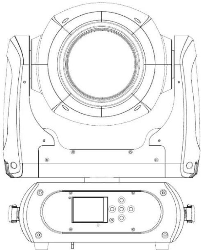
Geräteübersicht
(1) Objektivlinse
(2) Projektorarm
(3) Base
(4) Tragegriff
(5) Gummifuß
(6) Drahtlosanzeige
(7) Display
(8) Fangseilöse
(9) Mikrofon
(10) ESDC-Schalter
(11) Pfeil-Taste nach links
(12) Pfeil-Taste nach unten
(13) Enter-Taste
(14) Pfeil-Taste nach rechts
(15) Pfeil-Taste nach oben
(16) 3-poliger DMX-Eingangsstecker
(17) 5-poliger DMX-Eingangsstecker
(18) 3-polige DMX-Ausgangsbuchse
(19) 5-polige DMX-Ausgangsbuchse
(20) Spannungsversorgungseingang
(21) Spannungsversorgungsausgang
(22) Sicherungshalter
(23) Netzschalter
(24) Gehäuseschraube
INSTALLATION
Projektormontage
LEBENSGEFAHR!
Bei der Installation sind insbesondere die Bestimmungen der BGV C1 (vormals VBG 70) und EN 60598-2-17 zu beachten! Die Installation darf nur vom autorisierten Fachhandel ausgeführt werden!
Die Aufhängevorrichtungen des Projektors muss so gebaut und bemessen sein, dass sie 1 Stunde lang ohne dauernde schädliche Deformierung das 10-fache der Nutzlast aushalten kann.
Die Installation muss immer mit einer zweiten, unabhängigen Aufhängung, z. B. einem geeigneten Fangnetz, erfolgen. Diese zweite Aufhängung muss so beschaffen und angebracht sein, dass im Fehlerfall der Hauptaufhängung kein Teil der Installation herabfallen kann.
Während des Auf-, Um- und Abbaus ist der unnötige Aufenthalt im Bereich von Bewegungsflächen, auf Beleuchterbrücken, unter hochgelegenen Arbeitsplätzen sowie an sonstigen Gefahrbereichen verboten.
Der Unternehmer hat dafür zu sorgen, dass sicherheitstechnische und maschinentechnische Einrichtungen vor der ersten Inbetriebnahme und nach wesentlichen Änderungen vor der Wiederinbetriebnahme durch Sachverständige geprüft werden.
Der Unternehmer hat dafür zu sorgen, dass sicherheitstechnische und maschinentechnische Einrichtungen mindestens alle vier Jahre durch einen Sachverständigen im Umfang der Abnahmeprüfung geprüft werden.
Der Unternehmer hat dafür zu sorgen, dass sicherheitstechnische und maschinentechnische Einrichtungen mindestens einmal jährlich durch einen Sachkundigen geprüft werden.
Vorgehensweise:
Der Projektor sollte idealerweise außerhalb des Aufenthaltsbereiches von Personen installiert werden.
WICHTIG! ÜBERKOPFMONTAGE ERFORDERT EIN HOHES MAß AN ERFAHRUNG. Dies beinhaltet (aber beschränkt sich nicht allein auf) Berechnungen zur Definition der Tragfähigkeit, verwendetes Installationsmaterial und regelmäßige Sicherheitsinspektionen des verwendeten Materials und des Projektors. Versuchen Sie niemals, die Installation selbst vorzunehmen, wenn Sie nicht über eine solche Qualifikation verfügen, sondern beauftragen Sie einen professionellen Installateur. Unsachgemäße Installationen können zu Verletzungen und/oder zur Beschädigung von Eigentum führen.
Der Projektor muss außerhalb des Handbereichs von Personen installiert werden.
Wenn der Projektor von der Decke oder hochliegenden Trägern etc. abgehängt werden soll, muss immer mit Traversensystemen gearbeitet werden. Der Projektor darf niemals frei schwingend im Raum befestigt werden.
Achtung: Projektoren können beim Herabstürzen erhebliche Verletzungen verursachen! Wenn Sie Zweifel an der Sicherheit einer möglichen Installationsform haben, installieren Sie den Projektor NICHT!
Vergewissern Sie sich vor der Montage, dass die Montagefläche mindestens die 10-fache Punktbelastung des Eigengewichtes des Projektors aushalten kann.

BRANDGEFAHR!
Achten Sie bei der Installation des Gerätes bitte darauf, dass sich im Abstand von mind. 0,5 m keine leicht entflammbaren Materialien (Deko, etc.) befinden.
ACHTUNG!
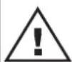
Montieren Sie den Projektor ausschließlich über einen geeigneten Haken. Bitte beachten Sie auch die Installationshinweise auf der Unterseite der Base. Achten Sie darauf, dass das Gerät sicher befestigt wird. Vergewissern Sie sich, dass die Verankerung stabil ist.
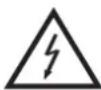
Die Projektorbase lässt sich auf zwei verschiedene Arten montieren.
natural_image
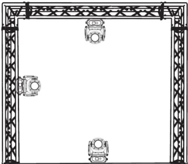
Technical line drawing of a rectangular frame with four camera modules and metal truss supports (no text or symbols)Das Gerät kann direkt auf den Boden gestellt werden oder in jeder möglichen Position im Trussing installiert werden, ohne seine funktionellen Eigenschaften zu verändern.
Beachten Sie bitte bei der vertikalen Installation im Trussing, dass der Omega-Halter immer parallel zum Trussing verläuft.
Sichern Sie den Projektor bei Überkopfmontage (Montagehöhe >100 cm) immer mit einem geeignetem Sicherungsseil.
Es dürfen nur Sicherungsseile und Schnellverbindungsglieder gemäß DIN 56927, Schäkel gemäß DIN EN 1677-1 und BGV C1 Kettbiner eingesetzt werden. Die Fangseile, Schnellverbindungsglieder, Schäkel und Kettbiner müssen auf Grundlage der aktuellsten
Arbeitsschutzbestimmungen (z. B. BGV C1, BGI 810-3) ausreichend dimensioniert sein und korrekt angewendet werden.
Bitte beachten Sie: Bei Überkopfmontage in öffentlichen bzw. gewerblichen Bereichen ist eine Fülle von Vorschriften zu beachten, die hier nur auszugsweise wiedergegeben werden können. Der Betreiber muss sich selbständig um die Beschaffung der geltenden Sicherheitsvorschriften bemühen und diese einhalten!
Der Hersteller haftet nicht für Schäden, die durch unsachgemäße Installation und unzureichende Sicherheitsvorkehrungen verursacht werden!
Hängen Sie das Schnellverschlussglied in dem dafür vorgesehenen Loch im Bodenblech ein. Führen Sie das Sicherungsseil über die Traverse bzw. einen sicheren Befestigungspunkt. Hängen Sie das Ende in dem Schnellverschlussglied ein und ziehen Sie die Sicherungsmutter gut fest.
Der maximale Fallabstand darf 20 cm nicht überschreiten.
Ein Sicherungsseil, das einmal der Belastung durch Absturz ausgesetzt war oder beschädigt ist, darf nicht mehr als Sicherungsseil eingesetzt werden.
LEBENSGEFAHR!
Vor der ersten Inbetriebnahme muss die Einrichtung durch einen Sachverständigen geprüft werden!
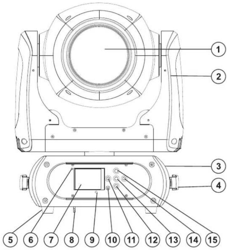
Verschrauben Sie einen Haken über eine M10 Schraube und selbstsichernde Mutter mit dem Omega-Halter.
Führen Sie die beiden Schnellverschlüsse des Omega-Halters in die dafür vorgesehenen Öffnungen an der Geräteunterseite ein. Drehen Sie die Schnellverschlüsse im Uhrzeigersinn bis zum Anschlag fest.

natural_image
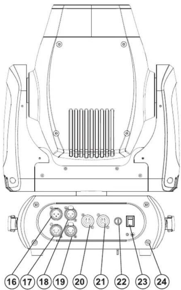
Technical line drawing of a mechanical device with mounting brackets and internal components (no text or symbols)Einbau des optionalen drahtlos-Empfängers für WDMX-Betrieb (FUTURELIGHT WDR-G4)
ACHTUNG! Vor Einbau des Moduls das Gerät vom Netz trennen. Gefahr eines elektrischen Schlages!
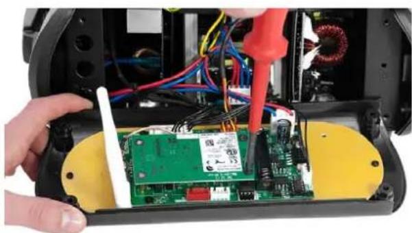
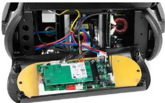
Installationsschritte
- Nehmen Sie den Drahtlos-DMX-Empfänger aus der Verpackung. Das Modul besteht aus einer Stabantenne mit Gewinde, der Wireless-Platine und einem Verbindungskabel.
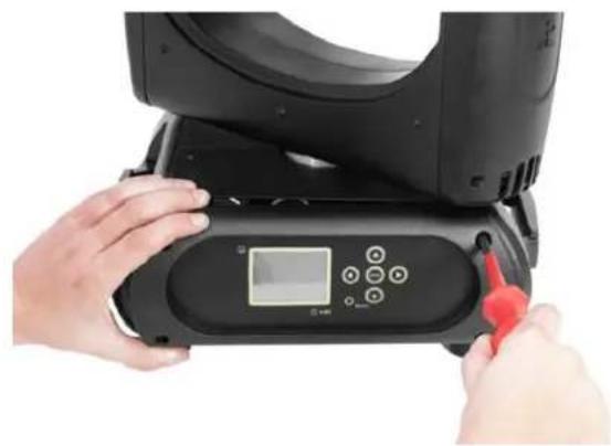
- Entfernen Sie nun die vier Schrauben des Control-Boards, an der Gerätevorderseite und klappen Sie die Control-Board-Abdeckung vorsichtig nach vorne. Auf der linken Seite des Display-Boards befinden sich die beiden Anschlussbuchsen für den Drahtlos-DMX-Empfänger.
- Schrauben Sie zuerst die Stabantenne auf der Antennenbuchse fest und legen Sie die Antenne entlang des Display-Boards in die Control-Board-Abdeckung.
- Zur Befestigung des Wireless-Moduls lösen Sie die drei Schrauben auf den Distanzbolzen und entfernen Sie sie. Stecken Sie die Steckkontakte des Wireless-Moduls in die Buchse auf dem Display-Board und schrauben die drei Schrauben wieder fest. Stecken Sie den Antennenstecker des Verbindungskabels in die dafür vorgesehene Buchse.
- Klappen Sie die Control-Board-Abdeckung vorsichtig wieder zu und schrauben die vier Schrauben an der Vorderseite wieder fest.
A
B
natural_image
Close-up of hands operating a black electronic device with a red tool inserted, no visible text or symbols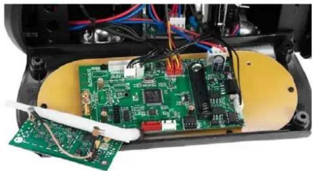
natural_image
Interior view of an electronic device showing a green circuit board with exposed wiring and components (no visible text or symbols)C
natural_image
Close-up of hands installing or repairing a green circuit board with wires and a red tool, no visible text or symbolsD
natural_image
Interior view of a robotic device showing exposed circuit board, wiring, and motor (no text or symbols visible)Deutsch
Anschluss an den DMX-512 Controller / Verbindung Projektor – Projektor

Achten Sie darauf, dass die Adern der Datenleitung an keiner Stelle miteinander in Kontakt treten. Die Geräte werden ansonsten nicht bzw. nicht korrekt funktionieren.


Beachten Sie, dass die Startadresse abhängig vom verwendeten Controller ist. Unbedingt Bedienungsanleitung des verwendeten Controllers beachten.
Die Verbindung zwischen Controller und Gerät sowie zwischen den einzelnen Geräten sollte mit einem DMX-Kabel erfolgen. Die Steckverbindung geht über 3- bzw. 5-polige XLR-Stecker und -Kupplungen.
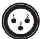
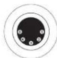
Belegung der XLR-Verbindung:
DMX-Ausgang
XLR-Einbaubuchse:
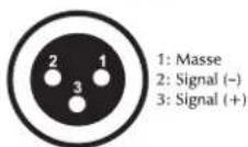
DMX-Eingang
XLR-Einbaustecker:
DMX-Ausgang
XLR-Einbaubuchse:
DMX-Eingang
XLR-Einbaustecker:
1: Masse
2: Signal (−)
3: Signal (+)
4: NC
5: NC

1: Masse
2: Signal (−)
3: Signal (+)
4: NC
5: NC
Wenn Sie Controller mit dieser XLR-Belegung verwenden, können Sie den DMX-Ausgang des Controllers direkt mit dem DMX-Eingang des ersten Gerätes der DMX-Kette verbinden. Sollen DMX-Controller mit anderen XLR-Ausgängen angeschlossen werden, müssen Adapterkabel verwendet werden.
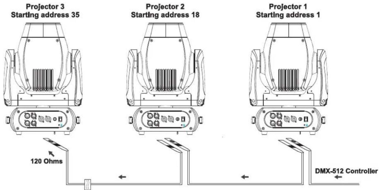
Aufbau einer seriellen DMX-Kette:
Schließen Sie den DMX-Ausgang des ersten Gerätes der Kette an den DMX-Eingang des nächsten Gerätes an. Verbinden Sie immer einen Ausgang mit dem Eingang des nächsten Gerätes bis alle Geräte angeschlossen sind. Nicht als Signalsplitter geeignet!
Achtung: Am letzten Gerät muss das DMX-Kabel durch einen Abschlusswiderstand abgeschlossen werden. Dazu wird ein XLR-Stecker in den DMX-Ausgang am letzten Gerät gesteckt, bei dem zwischen Signal (−) und Signal (+) ein 120 Ω Widerstand eingelötet ist.
Anschluss ans Netz
Schließen Sie das Gerät über die beiliegende Netzanschlussleitung ans Netz an.
Die Belegung der Anschlussleitungen ist wie folgt:
| Leitung | Pin | International |
| Braun | Außenleiter | L |
| Blau | Neutralleiter | N |
| Gelb/Grün | Schutzleiter |
Der Schutzleiter muss unbedingt angeschlossen werden!
Wenn das Gerät direkt an das örtliche Stromnetz angeschlossen wird, muss eine Trennvorrichtung mit mindestens 3 mm Kontaktöffnung an jedem Pol in die festverlegte elektrische Installation eingebaut werden.
Das Gerät darf nur an eine Elektroinstallation angeschlossen werden, die den VDE-Bestimmungen DIN VDE 0100 entspricht. Die Hausinstallation muss mit einem Fehlerstromschutzschalter (RCD) mit 30 mA Bemessungsdifferenzstrom ausgestattet sein.
Lichteffekte dürfen nicht über Dimmerpacks geschaltet werden.
Das Gerät ist mit einer verriegelbaren Netzanschlussbuchse ausgestattet. Schließen Sie das Netzkabel an und drehen Sie es nach rechts bis es einrastet. Stecken Sie den Netzstecker in eine geerdete Schutzkontaktsteckdose ein.
An der Rückseite der Geräte befindet sich eine Einbaubuchse (Power Out). Verbinden Sie den Ausgang mit dem Netzanschluss des nächsten Gerätes bis alle Geräte angeschlossen sind.
Bitte beachten: Es dürfen max. 8 Geräte in Reihe betrieben werden. Nach jeweils 8 Geräten muss erneut die Spannungsversorgung angeschlossen werden.
BEDIENUNG
Über den Netzschalter lässt sich das Gerät ein- bzw. ausschalten.
Wenn Sie das Gerät an die Spannungsversorgung angeschlossen haben, nimmt der DMB-160 den Betrieb auf. Während des Reset justieren sich die Motoren aus und das Gerät ist danach betriebsbereit.
Standalone-Betrieb
Der DMB-160 lässt sich im Standalone-Betrieb ohne Controller einsetzen. Trennen Sie dazu den DMB-160 vom Controller und rufen Sie das vorprogrammierte Programm auf. Bitte beachten Sie weitere Hinweise unter Control Board.
DMX-gesteuerter Betrieb
Über Ihren DMX-Controller können Sie die einzelnen Geräte individuell ansteuern. Dabei hat jeder DMX-Kanal eine andere Belegung mit verschiedenen Eigenschaften. Die einzelnen DMX-Kanäle und ihre Eigenschaften sind unter DMX-Protokoll aufgeführt.
Adressierung des Projektors
Über das Control Board können Sie die DMX-Startadresse definieren. Die Startadresse ist der erste Kanal, auf den der Projektor auf Signale vom Controller reagiert.
Wenn Sie die Startadresse, im 17 Kanal-Modus, z. B. auf 18 definieren, belegt der Projektor die Steuerkanäle 18 bis 34.
Deutsch
Bitte vergewissern Sie sich, dass sich die Steuerkanäle nicht mit anderen Geräten überlappen, damit der DMB-160 korrekt und unabhängig von anderen Geräten in der DMX-Kette funktioniert. Werden mehrere DMB-160 auf eine Adresse definiert, arbeiten sie synchron.
Drücken Sie die Up/Down-Tasten, um die gewünschte Startadresse einzustellen. Nun können Sie den DMB-160 über Ihren Controller ansteuern.
Bitte beachten Sie:
Schalten Sie das Gerät ein. Das Gerät prüft, ob DMX-512 Daten empfangen werden oder nicht. Werden keine Daten empfangen, blinkt das Display.
Die Meldung erscheint
-wenn kein XLR-Kabel (DMX Signalkabel vom Controller) in die DMX-Eingangsbuchse des Gerätes gesteckt wurde.
-wenn der Controller ausgeschaltet oder defekt ist.
-das Kabel oder der Stecker defekt ist oder das Signalkabel nicht richtig eingesteckt ist.
DMX-Protokoll
| Mode/Channel | Decimal | Hexad. | Percentage | S/F | Eigenschaft | ||||||
| St. | Ex. | Basic 8bit | Basic 16bit | ||||||||
| 1 | 1 | 1 | Horizontale Bewegung (PAN) | ||||||||
| 10 | 255 | 00 | FF | 0% | 100% | F | Wenn Sie den Regler verschieben, bewegen Sie den Kopf horizontal (PAN). Allmähliches Einstellen des Kopfes bei langsamen Schieben des Reglers (0-255, 128-Mitte). Der Kopf kann an jeder gewünschten Einstellung angehalten werden. | ||||
| 2 | 2 | PAN-Bewegung mit 16 Bit-Auflösung | |||||||||
| 0 | 255 | 00 | FF | 0% | 100% | F | Feinindizierung | ||||
| 2 | 3 | 2 | Vertikale Bewegung (TILT) | ||||||||
| 30 | 255 | 00 | FF | 0% | 100% | F | Wenn Sie den Regler verschieben, bewegen Sie den Kopf vertical (TILT). Allmähliches Einstellen des Kopfes bei langsamen Schieben des Reglers (0-255, 128-Mitte). Der Kopf kann an jeder gewünschten Einstellung angehalten werden. | ||||
| 4 | 4 | TILT-Bewegung mit 16 Bit-Auflösung | |||||||||
| 0 | 255 | 00 | FF | 0% | 100% | F | Feinindizierung | ||||
| 3 | 5 | 3 | 5 | Geschwindigkeit PAN-/TILT-Bewegung | |||||||
| 0 | 255 | 00 | FF | 0% | 100% | F | Abnehmende Geschwindigkeit | ||||
| 6 | Funktion PAN-/TILT-Bewegung | ||||||||||
| 0 | 15 | 00 | 0F | 0% | 6% | S | Normal | ||||
| 16 | 31 | 10 | 1F | 6% | 12% | S | Blackout bei PAN-/TILT-Bewegung | ||||
| 32 | 255 | 20 | FF | 13% | 100% | S | Keine Funktion | ||||
| 4 | 7 | Funktion Shutter, Strobe | |||||||||
| 0 | 15 | 00 | 0F | 0% | 6% | S | Normale Shutter Funktionen | ||||
| 16 | 31 | 10 | 1F | 6% | 12% | S | Öffnender Puls-Effekt | ||||
| 32 | 47 | 20 | 2F | 13% | 18% | S | Schließender Puls-Effekt | ||||
| 48 | 63 | 30 | 3F | 19% | 25% | S | Strobe-Effekt über Zufallsgenerator | ||||
Deutsch
| 64 | 255 | 40 | FF | 25% | 100% | S | Keine Funktion | ||||
| 5 | 8 | Shutter, Strobe | |||||||||
| Normale Shutter Funktionen | |||||||||||
| 0 | 31 | 00 | 1F | 0% | 12% | S | Geschlossen | ||||
| 32 | 223 | 20 | DF | 13% | 87% | F | Strobe-Effekt mit zunehmender Geschwindigkeit | ||||
| 224 | 255 | E0 | FF | 88% | 100% | Offen | |||||
| Öffnender Puls-Effekt | |||||||||||
| 0 | 31 | 00 | 1F | 0% | 12% | S | Geschlossen | ||||
| 32 | 223 | 20 | DF | 13% | 87% | F | Puls-Effekt mit zunehmender Geschwindigkeit | ||||
| 224 | 255 | E0 | FF | 88% | 100% | Offen | |||||
| Schließender Puls-Effekt | |||||||||||
| 0 | 31 | 00 | 1F | 0% | 12% | S | Geschlossen | ||||
| 32 | 223 | 20 | DF | 13% | 87% | F | Puls-Effekt mit zunehmender Geschwindigkeit | ||||
| 224 | 255 | E0 | FF | B8% | 100% | Offen | |||||
| Strobe-Effekt über Zufallsgenerator | |||||||||||
| 0 | 31 | 00 | 1F | 0% | 12% | S | Geschlossen | ||||
| 32 | 223 | 20 | DF | 13% | 87% | F | Strobe-Effekt mit zunehmender Geschwindigkeit | ||||
| 224 | 255 | E0 | FF | B8% | 100% | Offen | |||||
| 4 | 6 | Shutter, Strobe | |||||||||
| 0 | 31 | 00 | 1F | 0% | 12% | S | Shutter geschlossen | ||||
| 32 | 63 | 20 | 3F | 13% | 25% | S | Keine Funktion (Shutter offen) | ||||
| 64 | 95 | 40 | 5F | 25% | 37% | F | Strobe-Effekt mit zunehmender Geschwindigkeit | ||||
| 96 | 127 | 60 | 7F | 38% | 50% | S | Keine Funktion (Shutter offen) | ||||
| 128 | 159 | 80 | 9F | 50% | 62% | F | Puls-Effekt in Sequenzen | ||||
| 160 | 191 | A0 | BF | 63% | 75% | S | Keine Funktion (Shutter offen) | ||||
| 192 | 223 | C0 | DF | 75% | 87% | F | Strobe-Effekt über Zufallsgenerator mit zunehmender Geschwindigkeit | ||||
| 224 | 255 | E0 | FF | 88% | 100% | S | Keine Funktion (Shutter offen) | ||||
| 6 | 9 | 5 | 7 | Dimmerintensität | |||||||
| 0 | 255 | 00 | FF | 0% | 100% | F | Allmähliche Einstellung der Dimmerintensität von 0 bis 100 % | ||||
| 7 | 10 | Funktion Farben | |||||||||
| 0 | 15 | 00 | 0F | 0% | 6% | S | Normaler Farbwechsel | ||||
| 16 | 31 | 10 | 1F | 6% | 12% | S | Blackout bei Farbwechsel | ||||
| 32 | 47 | 20 | 2F | 13% | 18% | S | Rainboweffekt vorwärts | ||||
| 48 | 63 | 30 | 3F | 19% | 25% | S | Rainboweffekt rückwärts | ||||
| 64 | 79 | 40 | 4F | 25% | 31% | S | Farbwechsel an jeder Position | ||||
| 80 | 111 | 50 | 6F | 31% | 44% | S | Schneller Farbsprung | ||||
| 112 | 255 | 70 | FF | 44% | 100% | $ | Keine Funktion | ||||
| 8 | 11 | Farbrad | |||||||||
| Normaler Farbwechsel / Blackout bei Farbwechsel | |||||||||||
| 0 | 16 | 00 | 10 | 0% | 6% | S | Offen | ||||
| 17 | 33 | 11 | 21 | 7% | 13% | S | Position 1 | ||||
| 34 | 50 | 22 | 32 | 13% | 20% | S | Position 2 | ||||
Deutsch
| 51 | 67 | 33 | 43 | 20% | 26% | S | Position 3 | |||||
| 68 | 84 | 44 | 54 | 27% | 33% | S | Position 4 | |||||
| 85 | 101 | 55 | 65 | 33% | 40% | S | Position 5 | |||||
| 102 | 118 | 66 | 76 | 40% | 46% | S | Position 6 | |||||
| 119 | 135 | 77 | 87 | 47% | 53% | S | Position 7 | |||||
| 136 | 152 | 88 | 98 | 53% | 60% | S | Position 8 | |||||
| 153 | 169 | 99 | A9 | 60% | 66% | S | Position 9 | |||||
| 170 | 186 | AA | BA | 67% | 73% | S | Position 10 | |||||
| 187 | 203 | BB | CB | 73% | 80% | S | Position 11 | |||||
| 204 | 220 | CC | DC | 80% | 86% | S | Position 12 | |||||
| 221 | 237 | DD | ED | 87% | 93% | S | Position 13 | |||||
| 238 | 255 | EE | FF | 93% | 100% | S | Position 14 | |||||
| Rainboweffekt vorwärts | ||||||||||||
| 0 | 255 | 00 | FF | 0% | 100% | F | Mit zunehmender Geschwindigkeit | |||||
| Rainboweffekt rückwärts | ||||||||||||
| 0 | 255 | 00 | FF | 0% | 100% | F | Mit zunehmender Geschwindigkeit | |||||
| Farbwechsel an jeder Position | ||||||||||||
| 0 | 255 | 00 | FF | 0% | 100% | F | Positionierung von 0 - 360 Grad | |||||
| Schneller Farbsprung | ||||||||||||
| 0 | 8 | 00 | 08 | 0% | 3% | S | Offen | |||||
| 9 | 17 | 09 | 11 | 4% | 7% | S | Position 1 | |||||
| 18 | 26 | 12 | 1A | 7% | 10% | S | Position 2 | |||||
| 27 | 35 | 1B | 23 | 11% | 14% | S | Position 3 | |||||
| 36 | 44 | 24 | 2C | 14% | 17% | S | Position 4 | |||||
| 45 | 53 | 2D | 35 | 18% | 21% | S | Position 5 | |||||
| 54 | 62 | 36 | 3E | 21% | 24% | S | Position 6 | |||||
| 63 | 71 | 3F | 47 | 25% | 28% | S | Position 7 | |||||
| 72 | 80 | 48 | 50 | 28% | 31% | S | Position 8 | |||||
| 81 | 89 | 51 | 59 | 32% | 35% | S | Position 9 | |||||
| 90 | 98 | 5A | 62 | 35% | 38% | S | Position 10 | |||||
| 99 | 107 | 63 | 6B | 39% | 42% | S | Position 11 | |||||
| 108 | 116 | 6C | 74 | 42% | 45% | S | Position 12 | |||||
| 117 | 125 | 75 | 7D | 46% | 49% | S | Position 13 | |||||
| 126 | 134 | 7E | 86 | 49% | 53% | S | Position 14 | |||||
| 135 | 143 | 87 | 8F | 53% | 56% | S | Position 15 | |||||
| 144 | 152 | 90 | 98 | 56% | 60% | S | Position 16 | |||||
| 153 | 161 | 99 | A1 | 60% | 63% | S | Position 17 | |||||
| 162 | 170 | A2 | AA | 64% | 67% | S | Position 18 | |||||
| 171 | 179 | AB | B3 | 67% | 70% | S | Position 19 | |||||
| 180 | 188 | B4 | BC | 71% | 74% | S | Position 20 | |||||
| 189 | 197 | BD | C5 | 74% | 77% | S | Position 21 | |||||
| 198 | 206 | C6 | CE | 78% | 81% | S | Position 22 | |||||
| 207 | 215 | CF | D7 | 81% | 84% | S | Position 23 | |||||
| 216 | 224 | D8 | E0 | 85% | 88% | S | Position 24 | |||||
Deutsch
| 225 | 233 | E1 | E9 | 88% | 91% | S | Position 25 | |||||
| 234 | 242 | EA | F2 | 92% | 95% | S | Position 26 | |||||
| 243 | 251 | F3 | FB | 95% | 98% | S | Position 27 | |||||
| 252 | 255 | FC | FF | 99% | 100% | S | Position 28 | |||||
| 6 | 8 | Farbrad | ||||||||||
| Normaler Farbwechsel | ||||||||||||
| 0 | 2 | 00 | 02 | 0% | 1% | S | Offen | |||||
| 3 | 5 | 03 | 05 | 1% | 2% | S | Position 1 | |||||
| 6 | 8 | 06 | 08 | 2% | 3% | S | Position 2 | |||||
| 9 | 11 | 09 | 0B | 4% | 4% | S | Position 3 | |||||
| 12 | 14 | 0C | 0E | 5% | 5% | S | Position 4 | |||||
| 15 | 17 | 0F | 11 | 6% | 7% | S | Position 5 | |||||
| 18 | 20 | 12 | 14 | 7% | 8% | S | Position 6 | |||||
| 21 | 23 | 15 | 17 | 8% | 9% | S | Position 7 | |||||
| 24 | 26 | 18 | 1A | 9% | 10% | S | Position 8 | |||||
| 27 | 29 | 1B | 1D | 11% | 11% | S | Position 9 | |||||
| 30 | 32 | 1E | 20 | 12% | 13% | S | Position 10 | |||||
| 33 | 35 | 21 | 23 | 13% | 14% | S | Position 11 | |||||
| 36 | 38 | 24 | 26 | 14% | 15% | S | Position 12 | |||||
| 39 | 41 | 27 | 29 | 15% | 16% | S | Position 13 | |||||
| 42 | 44 | 2A | 2C | 16% | 17% | S | Position 14 | |||||
| Blackout bei Farbwechsel | ||||||||||||
| 45 | 47 | 2D | 2F | 18% | 18% | S | Offen | |||||
| 48 | 50 | 30 | 32 | 19% | 20% | S | Position 1 | |||||
| 51 | 53 | 33 | 35 | 20% | 21% | S | Position 2 | |||||
| 54 | 56 | 36 | 38 | 21% | 22% | S | Position 3 | |||||
| 57 | 59 | 39 | 3B | 22% | 23% | S | Position 4 | |||||
| 60 | 62 | 3C | 3E | 24% | 24% | S | Position 5 | |||||
| 63 | 65 | 3F | 41 | 25% | 25% | S | Position 6 | |||||
| 66 | 68 | 42 | 44 | 26% | 27% | S | Position 7 | |||||
| 69 | 71 | 45 | 47 | 27% | 28% | S | Position 8 | |||||
| 72 | 74 | 48 | 4A | 28% | 29% | S | Position 9 | |||||
| 75 | 77 | 4B | 4D | 29% | 30% | S | Position 10 | |||||
| 78 | 80 | 4E | 50 | 31% | 31% | S | Position 11 | |||||
| 81 | 83 | 51 | 53 | 32% | 33% | S | Position 12 | |||||
| 84 | 86 | 54 | 56 | 33% | 34% | S | Position 13 | |||||
| 87 | 89 | 57 | 59 | 34% | 35% | S | Position 14 | |||||
| Schneller Farbsprung | ||||||||||||
| 90 | 98 | 5A | 62 | 35% | 38% | F | Offen | |||||
| 99 | 107 | 63 | 6B | 39% | 42% | F | Position 1 | |||||
| 108 | 116 | 6C | 74 | 42% | 45% | F | Position 2 | |||||
| 117 | 125 | 75 | 7D | 46% | 49% | F | Position 3 | |||||
| 126 | 134 | 7E | 86 | 49% | 53% | F | Position 4 | |||||
| 135 | 143 | 87 | 8F | 53% | 56% | F | Position 5 | |||||
| 144 | 152 | 90 | 98 | 56% | 60% | F | Position 6 | |||||
| 153 | 161 | 99 | A1 | 60% | 63% | F | Position 7 | |||||
| 162 | 170 | A2 | AA | 64% | 67% | F | Position 8 | |||||
| 171 | 179 | AB | B3 | 67% | 70% | F | Position 9 | |||||
| 180 | 188 | B4 | BC | 71% | 74% | F | Position 10 | |||||
| 189 | 197 | BD | C5 | 74% | 77% | F | Position 11 | |||||
| 198 | 206 | C6 | CE | 78% | 81% | F | Position 12 | |||||
| 207 | 215 | CF | D7 | 81% | 84% | F | Position 13 | |||||
| 216 | 223 | D8 | DF | 85% | 87% | F | Position 14 | |||||
Deutsch
| Rainboweffekt vorwärts | |||||||||||
| 224 | 239 | E0 | EF | 88% | 94% | F | Mit zunehmender Geschwindigkeit | ||||
| Rainboweffekt rückwärts | |||||||||||
| 240 | 255 | F0 | FF | 94% | 100% | F | Mit zunehmender Geschwindigkeit | ||||
| 9 | 12 | Funktion statisches Goborad, Gobo-Shake | |||||||||
| 0 | 15 | 00 | 0F | 0% | 6% | S | Normaler Gobowechsel | ||||
| 16 | 31 | 10 | 1F | 6% | 12% | S | Blackout bei Gobowechsel | ||||
| 32 | 47 | 20 | 2F | 13% | 18% | S | Rotierendes Goborad vorwärts | ||||
| 48 | 63 | 30 | 3F | 19% | 25% | S | Rotierendes Goborad rückwärts | ||||
| 64 | 79 | 40 | 4F | 25% | 31% | S | Gobowechsel an jeder Position | ||||
| 80 | 95 | 50 | 5F | 31% | 37% | S | Gobo-Shake | ||||
| 96 | 255 | 60 | FF | 38% | 100% | S | Keine Funktion | ||||
| 10 | 13 | Statisches Goborad, Gobo-Shake | |||||||||
| Normaler Gobowechsel / Blackout bei Gobowechsel / Gobo-Shake | |||||||||||
| 0 | 13 | 00 | 0D | 0% | 5% | S/F | Offen | ||||
| 14 | 27 | 0E | 1B | 5% | 11% | S/F | Position 1 | ||||
| 28 | 41 | 1C | 29 | 11% | 16% | S/F | Position 2 | ||||
| 42 | 55 | 2A | 37 | 16% | 22% | S/F | Position 3 | ||||
| 56 | 69 | 38 | 45 | 22% | 27% | S/F | Position 4 | ||||
| 70 | 83 | 46 | 53 | 27% | 33% | S/F | Position 5 | ||||
| 84 | 97 | 54 | 61 | 33% | 38% | S/F | Position 6 | ||||
| 98 | 111 | 62 | 6F | 38% | 44% | S/F | Position 7 | ||||
| 112 | 125 | 70 | 7D | 44% | 49% | S/F | Position 8 | ||||
| 126 | 139 | 7E | 8B | 49% | 55% | S/F | Position 9 | ||||
| 140 | 153 | 8C | 99 | 55% | 60% | S/F | Position 10 | ||||
| 154 | 167 | 9A | A7 | 60% | 65% | S/F | Position 11 | ||||
| 168 | 181 | A8 | B5 | 66% | 71% | S/F | Position 12 | ||||
| 182 | 195 | B6 | C3 | 71% | 76% | S/F | Position 13 | ||||
| 196 | 209 | C4 | D1 | 77% | 82% | S/F | Position 14 | ||||
| 210 | 223 | D2 | DF | 82% | 87% | S/F | Position 15 | ||||
| 224 | 237 | E0 | ED | 88% | 93% | S/F | Position 16 | ||||
| 238 | 255 | EE | FF | 93% | 100% | S/F | Position 17 | ||||
| Rotierendes Goborad vorwärts | |||||||||||
| 0 | 255 | 00 | FF | 0% | 100% | F | Mit zunehmender Geschwindigkeit | ||||
| Rotierendes Goborad rückwärts | |||||||||||
| 0 | 255 | 00 | FF | 0% | 100% | F | Mit zunehmender Geschwindigkeit | ||||
| Gobowechsel an jeder Position | |||||||||||
| 0 | 255 | 00 | FF | 0% | 100% | F | Positionierung von 0 - 360 Grad | ||||
| 7 | 9 | Statisches Goborad, Gobo-Shake | |||||||||
| Normaler Gobowechsel | |||||||||||
| 0 | 1 | 00 | 01 | 0% | 0% | S | Offen | ||||
| 2 | 3 | 02 | 03 | 1% | 1% | S | Position 1 | ||||
| 4 | 5 | 04 | 05 | 2% | 2% | S | Position 2 | ||||
Deutsch
| 6 7 | 06 | 07 | 2% | 3% | S | Position 3 | |
| 8 9 | 08 | 09 | 3% | 4% | S | Position 4 | |
| 10 11 | 0A | 0B | 4% | 4% | S | Position 5 | |
| 12 13 | 0C | 0D | 5% | 5% | S | Position 6 | |
| 14 15 | 0E | 0F | 5% | 6% | S | Position 7 | |
| 16 17 | 10 | 11 | 6% | 7% | S | Position 8 | |
| 18 19 | 12 | 13 | 7% | 7% | S | Position 9 | |
| 20 21 | 14 | 15 | 8% | 8% | S | Position 10 | |
| 22 23 | 16 | 17 | 9% | 9% | S | Position 11 | |
| 24 25 | 18 | 19 | 9% | 10% | S | Position 12 | |
| 26 27 | 1A | 1B | 10% | 11% | S | Position 13 | |
| 28 29 | 1C | 1D | 11% | 11% | S | Position 14 | |
| 30 31 | 1E | 1F | 12% | 12% | S | Position 15 | |
| 32 33 | 20 | 21 | 13% | 13% | S | Position 16 | |
| 34 35 | 22 | 23 | 13% | 14% | S | Position 17 | |
| Blackout bei Gobowechsel | |||||||
| 36 | 37 | 24 | 25 | 14% | 15% | S | Offen |
| 38 39 | 26 | 27 | 15% | 15% | S | Position 1 | |
| 40 41 | 28 | 29 | 16% | 16% | S | Position 2 | |
| 42 43 | 2A | 2B | 16% | 17% | S | Position 3 | |
| 44 45 | 2C | 2D | 17% | 18% | S | Position 4 | |
| 46 47 | 2E | 2F | 18% | 18% | S | Position 5 | |
| 48 49 | 30 | 31 | 19% | 19% | S | Position 6 | |
| 50 51 | 32 | 33 | 20% | 20% | S | Position 7 | |
| 52 53 | 34 | 35 | 20% | 21% | S | Position 8 | |
| 54 55 | 36 | 37 | 21% | 22% | S | Position 9 | |
| 56 57 | 38 | 39 | 22% | 22% | S | Position 10 | |
| 58 59 | 3A | 3B | 23% | 23% | S | Position 11 | |
| 60 61 | 3C | 3D | 24% | 24% | S | Position 12 | |
| 62 63 | 3E | 3F | 24% | 25% | S | Position 13 | |
| 64 65 | 40 | 41 | 25% | 25% | S | Position 14 | |
| 66 67 | 42 | 43 | 26% | 26% | S | Position 15 | |
| 68 69 | 44 | 45 | 27% | 27% | S | Position 16 | |
| 70 71 | 46 | 47 | 27% | 28% | S | Position 17 | |
| Gobo-Shake | |||||||
| 72 80 | 48 | 50 | 28% | 31% | F | Position 1 | |
| 81 89 | 51 | 59 | 32% | 35% | F | Position 2 | |
| 90 | 98 | 5A | 62 | 35% | 38% | F | Position 3 |
| 99 | 107 | 63 | 6B | 39% | 42% | F | Position 4 |
| 108 | 116 | 6C | 74 | 42% | 45% | F | Position 5 |
| 117 | 125 | 75 | 7D | 46% | 49% | F | Position 6 |
| 126 | 134 | 7E | 86 | 49% | 53% | F | Position 7 |
| 135 | 143 | 87 | 8F | 53% | 56% | F | Position 8 |
| 144 | 152 | 90 | 98 | 56% | 60% | F | Position 9 |
Deutsch
| 153 | 161 | 99 | A1 | 60% | 63% | F | Position 10 | |||||
| 162 | 170 | A2 | AA | 64% | 67% | F | Position 11 | |||||
| 171 | 179 | AB | B3 | 67% | 70% | F | Position 12 | |||||
| 180 | 188 | B4 | BC | 71% | 74% | F | Position 13 | |||||
| 189 | 197 | BD | C5 | 74% | 77% | F | Position 14 | |||||
| 198 | 206 | C6 | CE | 78% | 81% | F | Position 15 | |||||
| 207 | 215 | CF | D7 | 81% | 84% | F | Position 16 | |||||
| 216 | 223 | D8 | DF | 85% | 87% | F | Position 17 | |||||
| Rotierendes Goborad vorwärts | ||||||||||||
| 224 | 224 | E0 | E0 | 88% | 88% | S | Stop | |||||
| 225 | 239 | E1 | EF | 88% | 94% | F | Mit zunehmender Geschwindigkeit | |||||
| Rotierendes Goborad rückwärts | ||||||||||||
| 240 | 240 | F0 | F0 | 94% | 94% | S | Stop | |||||
| 241 | 255 | F1 | FF | 95% | 100% | F | Mit zunehmender Geschwindigkeit | |||||
| 11 | 14 | 8 | 10 | Prisma | ||||||||
| 0 | 63 | 00 | 3F | 0% | 25% | S | Offen | |||||
| 64 | 127 | 40 | 7F | 25% | 50% | S | 6-fach-linear-Prisma | |||||
| 128 | 191 | 80 | BF | 50% | 75% | S | 8-Facetten-Prisma | |||||
| 192 | 255 | C0 | FF | 75% | 100% | S | Frost | |||||
| 12 | 15 | 9 | 11 | Prismenrotation | ||||||||
| Prismenrotation an jeder Position | ||||||||||||
| 0 | 191 | 00 | BF | 0% | 75% | F | Positionierung von 0 - 360 Grad | |||||
| Rotierendes Prisma vorwärts | ||||||||||||
| 192 | 223 | C0 | DF | 75% | 87% | F | Mit zunehmender Geschwindigkeit (Stop bis schnellste Geschwindigkeit) | |||||
| Rotierendes Prisma rückwärts | ||||||||||||
| 224 | 255 | E0 | FF | 88% | 100% | F | Mit zunehmender Geschwindigkeit (Stop bis schnellste Geschwindigkeit) | |||||
| 13 | 16 | 10 | 12 | Fokus | ||||||||
| 0 | 255 | 00 | FF | 0% | 100% | F | Allmähliche Einstellung von nah bis weit | |||||
| 14 | 17 | 11 | 13 | Reset, Displaysteuerung | ||||||||
| 0 | 7 | 00 | 07 | 0% | 3% | S | Keine Funktion | |||||
| 8 | 15 | 08 | 0F | 3% | 6% | S | Reset Alle | |||||
| 16 | 23 | 10 | 17 | 6% | 9% | S | Reset PAN/TILT | |||||
| 24 | 31 | 18 | 1F | 9% | 12% | S | Reset Farben | |||||
| 32 | 39 | 20 | 27 | 13% | 15% | S | Reset Gobos | |||||
| 40 | 47 | 28 | 2F | 16% | 18% | S | Keine Funktion | |||||
| 48 | 55 | 30 | 37 | 19% | 22% | S | Reset Übrige | |||||
| 56 | 63 | 38 | 3F | 22% | 25% | S | Display aus | |||||
| 64 | 71 | 40 | 47 | 25% | 28% | S | Display an | |||||
| 72 | 79 | 48 | 4F | 28% | 31% | S | Keine Funktion | |||||
| 80 | 87 | 50 | 57 | 31% | 34% | S | Keine Funktion | |||||
| 88 | 95 | 58 | 5F | 35% | 37% | S | Standby-Modus | |||||
| 96 | 255 | 60 | FF | 38% | 100% | S | Keine Funktion | |||||
Deutsch
Control Board
Das Control Board bietet mehrere Möglichkeiten: so lassen sich z. B. die DMX-Startadresse eingeben, das vorprogrammierte Programm abspielen oder ein Reset durchführen.
Drücken Sie die Enter-Taste, so dass sich das Display einschaltet. Durch Drücken der geeigneten Pfeil-Taste (nach unten, nach oben, nach links und nach rechts) können Sie sich im Hauptmenü bewegen. Zur Auswahl des gewünschten Menüpunktes drücken Sie die Enter-Taste. Durch Drücken der geeigneten Pfeil-Taste können Sie die Auswahl verändern. Bestätigen Sie jede Änderung durch Drücken der Enter-Taste. Die jeweiligen Funktionen werden im Folgenden beschrieben.
Vorgabewerte grau unterlegt ① Basic Reload / ② Program Reload / ③ Private Reload
| Hauptmenü | Untermenü | Display | |
| Connect | DMX Address 1 | ||
| Wireless 1 | |||
| Light | Max Temperature 1 | 80-139°C,90°C/176-282°F,194°F | |
| Lamp Adjust | PAN ... | Service-Funktion | |
| Information | Time info | Current | XXXX |
| Fixture Life XXXX (h) Betriebsstunden Gerät | |||
| Temperature Near Lamp Temp. ... XXX | °C/°F Innentemperatur | ||
| Fans Speed Near Lamp Fan | Lüftergeschwindigkeit | ||
| Channel Value | PAN ... | PAN = XXX ... | |
| Error Message | PAN, TILT ... | ||
| Fixture Model | Xxxxxxxxxxxxxx | ||
| Software Ver | 1U01 V 1.0.002U01 V 1.0.00 ... | ||
| Set | Reset | All | |
| PAN&TILT | |||
| Colors | |||
| Gobos | |||
| Others | |||
| Movement 1 | PAN reverse | ON/OFF | |
| TILT reverse | ON/OFF | ||
| PAN degree | 630/540 | ||
| Encoders | ON/OFF | ||
| PAN/TILT Mode | Stand/Smooth | ||
| UI Set | Mic Sens 3 | 0~99%, 60% | |
| No Signal 1 | Close/Hold/Auto/Music | ||
| Temperature C/F 1 | Celsius/Fahrenheit | ||
| Fans Mode 1 | Auto Speed/High Speed | ||
| Hibernation 1 | OFF, 01M-99M, 15M | ||
| Backlight 1 | 02M-60M, 02M | ||
| Flip Display 1 | ON/OFF | ||
| Display Bright 3 | 00-31 10 | ||
| Brand Show 1 | ON/OFF | ||
| Key Lock 1 | ON/OFF | ||
| Language 3 | En/简/繁/Fr/Sp | ||
Funk
Deutsch
| Set | Users | User Mode 1 | StandardExtendedBasic-8bitBasic-16bitUser | Benutzerdefinierte Kanalreihenfolge |
| Edit User 3 | Max Channel = XXPAN = CH01 ... | Preset-Benutzerd. | ||
| Calibration 3 | --Password--Color ... | Password=XXXColor =XXX ... | Effektradjustierung; StandardpositionPasswort „050“ | |
| Fixture ID 3 | Name--Password--PID Code | NamePasswort „050“PID-Code für RDM einstellen | ||
| Wireless Set 3 | DMX on cableReset Connect | ON/OFFON/OFF | Durchschleifen von DatenEmpfänger ausloggen(Sonderausstattung optional) | |
| Reload Default | Basic Reload 1Program Reload 2--Password--Private Reload 3All Reload | ON/OFFON/OFFXXXON/OFFON/OFF | Basis ReloadProgramm ReloadPassword: 050Privater ReloadReload Alles | |
| Program | Play 1 | DMX receive Zurück zum DMX-Mode | ||
| Slave receive Slave | 1, Slave 2, Slave 3 Slave-Einstellung | |||
| Sequence Master/Alone Autom. Programm Run | ||||
| Music | Master/Alone | MusikgesteuerterProgramm Run | ||
| Select Chase 2 | Chase Part 1Chase Part 2Chase Part 3 | Chase 1-8 Chase 1Chase 1-8 Chase 2Chase 1-8 Chase 3 | Programmwahl für AutoProgramm | |
| Edit Chase 2 | Chase 1:Chase 8 | Chase TestStep 01 = SCXXXStep 64 = SCXXX | TestprogrammProgramm Auto RunSpeichern + los | |
| Edit Scenes 2 | Edit scene 001:Edit scene 250 | Pan,Tilt, ...-- Fade Time ---- Scene Time --DMX Input | Speichern + zurückSzenen manuell editieren | |
| Scenes Record Sc | XX=>ScXX | Automatische Szenenaufzeichnung | ||
Connect
Einstellen der DMX-Startadresse
Mit dieser Funktion können Sie die DMX-Startadresse über das Control Board einstellen.
- Wählen Sie "DMX Address" durch Drücken der Up/Down-Tasten.
- Drücken Sie die Enter-Taste und stellen Sie die DMX-Adresse durch Drücken der Up/Down-Tasten ein.
- Drücken Sie die Enter-Taste zur Bestätigung.
Wireless
Dieser Projektor ist ab Werk für drahtlose DMX-Übertragung (W-DMX) eingerichtet.
Mit der Funktion „Wireless“ können Sie den Drahtlos-Empfänger am Drahtlos-Sender einloggen, das Gerät
kann nun drahtlose Signale empfangen.
- Wählen Sie "Wireless" durch Drücken der Up/Down-Tasten.
- Drücken Sie die Enter-Taste zur Bestätigung.
Ist ein Gerät mit eingebautem Drahtlos-Empfänger über ein Kabel mit einem DMX-Controller verbunden, wird es von dem kabelgebundenen Controller angesteuert und nicht vom Drahtlos-Sender.
Deutsch
Light
Max Temperatur
Mit dieser Funktion kann das Gerät so programmiert werden, dass die LED automatisch abgeschaltet wird, wenn eine bestimmte Innentemperatur erreicht wird. Drücken Sie die Up/Down-Tasten zur Auswahl der maximalen Innentemperatur zwischen 80 °C und 139 °C. Die normale Betriebstemperatur sollte unter 90 °C liegen. 90 °C Innentemperatur und mehr sind bereits als kritisch zu bewerten und sollten zur Abschaltung der LED führen. Bitte beachten Sie, dass die Umgebungstemperatur niemals über 45 °C liegen sollte, damit eine ausreichende Kühlung gewährleistet ist.
Information
Time information
Betriebsstunden Gerät seit dem Einschalten (current)
Mit dieser Funktion lassen sich die temporären Betriebsstunden des Gerätes seit dem Einschalten auslesen. Auf dem Display erscheint "XXXX", "X" steht für die Anzahl der Stunden. Der Zähler wird beim Abschalten auf 0 zurückgesetzt.
Betriebsstunden Gerät (Fixture Life)
Mit dieser Funktion lassen sich die Betriebsstunden des Gerätes auslesen. Auf dem Display erscheint "XXXX", "X" steht für die Anzahl der Stunden.
Temperatur
Innentemperatur
Temperaturangabe im Inneren des Projektorkopfes (nahe CMY-Filter) in Grad Celsius/Grad Fahrenheit.
...
Lüftergeschwindigkeit
Mit dieser Funktion lässt sich die aktuelle Lüftergeschwindigkeit auslesen. Auf dem Display erscheint "XXXX", "X" steht für U/min.
DMX-Anzeiger
Mit dieser Funktion können Sie auslesen, mit welchem Wert der entsprechende Kanal gesendet wird.
Kanalfehler
Mit dieser Funktion können Sie Kanal Fehler auslesen.
Gerätemodell
Mit dieser Funktion können Sie das Modell und die Marke des Gerätes auslesen.
Software version
Mit dieser Funktion lässt sich die Software-Version jedes ICs auslesen.
- Wählen Sie "Software ver." durch Drücken der Up/Down-Tasten.
- Drücken Sie die Enter-Taste, auf dem Display erscheint z. B. "1U01 VX.X.XX", "X.X.xx" steht für die Versionsnummer.
Set
Reset
Mit dieser Funktion lässt sich über das Control Board ein Reset durchführen. Dabei können Sie über die Up/Down-Tasten die verschiedenen Reset-Funktionen auswählen.
Movement
PAN-Umkehr
Mit dieser Funktion lässt sich die PAN-Bewegung umkehren.
TILT-Umkehr
Mit dieser Funktion lässt sich die TILT-Bewegung umkehren.
PAN-Winkel zwischen 630° und 540° umschalten
Mit dieser Funktion lässt sich der PAN-Winkel einstellen.
- Wählen Sie "Pan degree" durch Drücken der Up/Down-Tasten.
- Drücken Sie die Enter-Taste, auf dem Display erscheint "540".
- Drücken Sie die Up/Down-Taste, um "540" oder "630" auszuwählen.
- Drücken Sie die Enter-Taste zur Bestätigung.
Deutsch
Automatische PAN/TILT Kalibrierung
Mit der Funktion "Encoders" lassen sich die PAN- und TILT-Bewegung auf die korrekten Ausgangspositionen kalibrieren.
PAN/TILT Geschwindigkeit einstellen
Mit dieser Funktion können Sie die PAN/TILT Geschwindigkeit definieren. Sie haben die Wahl zwischen zwei unterschiedlichen Modi.
UI Set
Mikrofonempfindlichkeit
Mit dieser Funktion lässt sich die Mikrofonempfindlichkeit zwischen 0 % und 99 % einstellen.
- Wählen Sie "Mic Sens" durch Drücken der Up/Down-Tasten.
- Drücken Sie die Up/Down-Taste, um die gewünschte Empfindlichkeit einzustellen.
- Drücken Sie die Enter-Taste zur Bestätigung.
Auto-Modus wenn kein DMX
Mit der Funktion "No Signal" lassen sich verschiedene Modi einstellen, wenn kein DMX-Signal empfangen wird.
- Wählen Sie "Close, Hold, Auto oder Music" durch Drücken der Up/Down-Tasten.
- Drücken Sie die Up/Down-Taste, um "Close", "Hold", "Auto" oder "Music" auszuwählen.
- Drücken Sie die Enter-Taste zur Bestätigung.
Temperatureinheit zwischen Grad Celsius und Grad Fahrenheit umschaltbar
Mit dieser Funktion lässt sich die Temperaturangabe einstellen.
- Wählen Sie "Temperature C/F" durch Drücken der Up/Down-Tasten.
- Drücken Sie die Up/Down-Taste, um "Celsius" oder "Fahrenheit" auszuwählen.
- Drücken Sie die Enter-Taste zur Bestätigung.
Lüfter Betriebsart einstellen
Mit dieser Funktion lässt sich die Lüfter Betriebsart einstellen.
- Wählen Sie "Fans Mode" durch Drücken der Up/Down-Tasten.
- Drücken Sie die Enter-Taste, auf dem Display erscheint "Auto Speed"
- Drücken Sie die Up/Down-Taste, um "Auto Speed" oder "High Speed" auszuwählen.
- Drücken Sie die Enter-Taste zur Bestätigung.
Hibernation- Power-Standby-Modus
Mit dieser Funktion lässt sich das Gerät in den Power-Standby-Modus setzen. Die Funktion wird automatisch nach einer vordefinierten Zeitspanne ohne DMX-Aktivität ausgeführt. Im Standby-Modus werden die Lampe/LEDs und alle Motoren abgeschalten, sofern für eine Zeitspanne von z. B. 15 Minuten (individuell einstellbar) kein DMX-Signal an das Gerät gesendet wurde. Das Gerät startet automatisch neu und kehrt zum Normalbetrieb zurück, sobald ein DMX-Signal anliegt.
Display-Abschaltung
Mit der Funktion „Backlight“ lässt sich das Display nach 2 bis 60 Minuten abschalten.
Display-Umkehrung
Mit der Funktion „Flip Display“ lässt sich das Display um 180 Grad drehen; für eine bessere Ansicht wenn das Gerät vom Trussing oder einer Decke hängt.
Display-Helligkeit
Mit der Funktion „Display Bright“ lässt sich die Display-Helligkeit einstellen.
Markennamen anzeigen
Mit der Funktion „Brand Show“ kann der Markenname "FUTURELIGHT" angezeigt oder ausgeblendet werden.
Tastensperre
Mit der Funktion „Key Lock“ können Sie die Tasten des Control Boards sperren, um z.B. ein Eingreifen Unbefugter zu verhindern. Wenn diese Funktion aktiviert wurde, werden die Tasten automatisch nach dem letzten Befehl, gesperrt. Drücken Sie, um die Tastensperre zu deaktivieren oder zeitweilig zu deaktivieren und um den Zugriff auf die Menübefehle zurückzugewinnen, die Tasten in der folgenden Reihenfolge:
↑ (nach oben), ↓ (nach unten), ← (nach links), → (nach rechts) und ENTER.
Display-Sprachauswahl
Mit der Funktion „Language“ lässt sich die Display-Sprachauswahl einstellen.
Deutsch
Users
Benutzerdefinierte Kanalreihenfolge
Mit dieser Funktion lassen sich benutzerdefinierte Kanalreihenfolgen abspeichern.
Preset-Benutzerdefinition
Mit dieser Funktion lässt sich Preset-Benutzerdefinition abspeichern.
Calibration
Effektradjustierung
Mit dieser Funktion lassen sich die Effekträder auf die korrekten Ausgangspositionen kalibrieren. Das Passwort für diese Funktion ist „050“.
Fixture ID
RDM
Mit dieser Funktion können Sie diverse Menüpunkte per RDM abrufen.
Das Gerät unterstützt RDM. Die Abkürzung RDM steht für "Remote Device Management" und macht eine Fernabfrage bzw. Fernsteuerung der an den DMX-Bus angeschlossenen Geräte möglich. Der DMX-RDM-Standard ist als ANSI-Norm E1.20-2006 durch die ESTA spezifiziert und eine Erweiterung des DMX512-Protokolls.
Manuelle Einstellungen, wie das Setzen der DMX-Startadresse, werden damit überflüssig. Besonders vorteilhaft ist diese Art der Steuerung, wenn das Gerät z. B. an schwierig erreichbaren Stellen montiert ist.
RDM integriert sich in DMX, ohne die Verbindung zu beeinträchtigen. Die Übertragung erfolgt auf den Standard-XLR-Polen 1 und 2 – neue DMX-Kabel sind daher nicht erforderlich. RDM-fähige und konventionelle DMX-Geräte können gemeinsam in einer DMX-Reihe betrieben werden. Das RDM-Protokoll sendet innerhalb eines DMX512-Datenstromes eigene Datenpakete, ohne nicht RDM-fähige Geräte zu beeinflussen.
Werden DMX-Splitter verwendet, und die Steuerung per RDM soll Anwendung finden, müssen diese RDM unterstützen.
Welche Parameter RDM unterstützt abgerufen werden können, ist abhängig vom verwendeten RDM-Controller (optional erhältlich).
Wireless Set
Mit der Funktion "DMX on cable" können Sie das DMX-Signal per DMX-Kabel durchschleifen und mit der Funktion "Reset Connect" lässt sich das Gerät am Drahtlos-Sender ausloggen.
Zurücksetzen auf Werkseinstellungen
Mit der Funktion „Reload Default“ lassen sich die verschiedenen Einstellungen (in der Tabelle gekennzeichnet) des Gerätes auf die Werkseinstellungen zurücksetzen. Die Einstellungen werden auf Ihren Vorgabewert (grau unterlegt) zurückgesetzt.
Program
Play
DMX Receive
Mit dieser Funktion lässt sich das Gerät in den DMX-Modus schalten.
Slave Receive
Mit dieser Funktion können Sie das Gerät als Slave-Gerät definieren. Sie haben die Wahl zwischen 3 unterschiedlichen Slave-Programmen. Weitere Informationen hierzu finden Sie unter „Edit Prog“.
Sequence
Mit dieser Funktion lässt sich das interne Programm aufrufen. Das gewünschte Programm können Sie unter „Select Chase“ auswählen. Die Anzahl der Steps können Sie unter „Edit Chase“ festlegen. Die einzelnen Szenen können Sie unter „Edit Scenes“ abändern. Mit dieser Funktion lassen sich die Szenen automatisch, d.h. mit der eingestellten Step-Time abspielen. Die Auswahl „ALONE“ bedeutet Stand Alone-Modus und „MASTER“, dass das Gerät als Master-Gerät definiert wird.
Deutsch
Musiksteuerung
Mit dieser Funktion lässt sich das interne Programm aufrufen. Mit dieser Funktion lassen sich die Szenen musikgesteuert abspielen. Die Auswahl „ALONE“ bedeutet Stand Alone-Modus und „MASTER“, dass das Gerät als Master-Gerät definiert wird.
Programmwahl für Auto Programm
Mit dieser Funktion lässt sich das Programm festlegen, das dann im Run aufgerufen wird.
Programm editieren
Mit dieser Funktion lassen sich die internen Programme editieren.
Szenen editieren
Mit dieser Funktion lassen sich die Szenen der internen Programme editieren.
Szenen automatisch aufzeichnen
Das Gerät verfügt über einen internen DMX-Recorder, mit dem sich programmierte Szenen aus dem DMX-Controller auf das Gerät übertragen lassen. Stellen Sie die gewünschten Szenen-Nummern über die Up/Down-Tasten ein (von – bis). Wenn Sie nun die Szenen auf Ihrem Controller aufrufen, werden diese automatisch auf das Gerät übertragen.
Exkurs:
Ein Mastergerät kann 3 verschiedene Datengruppen zu den Slavegeräten senden. Das bedeutet, dass ein Mastergerät 3 verschiedene Slaveeinheiten starten kann, in welchen 3 unterschiedliche Programme ablaufen. Die Mastereinheit sendet die 3 Programmteile in Schleife.
Das Slavegerät empfängt die Daten vom Mastergerät nach der Gruppe, in die das Slavegerät eingeordnet wurde. Ist z.B. ein Slavegerät im Menü „Slave“ auf „Slave 1“ eingestellt wird das „Chase Part 1“ vom Master gesendet und vom Slave empfangen. Ist „Slave 2“ eingestellt, empfängt es das „Chase Part 2“.
Zum Starten eines Auto Programmes gehen Sie bitte wie folgt vor:
-
Slave-Einstellung
-
Wählen Sie "Program" durch Drücken der Up/Down-Tasten.
- Drücken Sie die Enter-Taste zur Bestätigung.
- Wählen Sie "Slave" durch Drücken der Up/Down-Tasten.
- Drücken Sie die Enter-Taste zur Bestätigung.
- Drücken Sie die Enter-Taste zur Bestätigung.
- Drücken Sie die Up/Down-Taste, um "Slave 1" oder "Slave 2" oder "Slave 3" einzustellen.
-
Automatischer Program Run
-
Wählen Sie "Program" durch Drücken der Up/Down-Tasten.
- Drücken Sie die Enter-Taste zur Bestätigung.
- Wählen Sie "Sequence" durch Drücken der Up/Down-Tasten.
- Drücken Sie die Enter-Taste zur Bestätigung.
- Drücken Sie die Up/Down-Taste, um "Master" oder "Alone" auszuwählen. „ALONE" bedeutet Stand Alone-Modus und „MASTER“, dass das Gerät als Master-Gerät definiert wird.
-
Drücken Sie die Enter-Taste zur Bestätigung.
-
Programmwahl für Select Chase
-
Wählen Sie "Edit Chase" durch Drücken der Up/Down-Tasten.
- Drücken Sie die Enter-Taste zur Bestätigung.
- Wählen Sie "Select Chase" durch Drücken der Up/Down-Tasten.
- Drücken Sie die Enter-Taste zur Bestätigung.
- Drücken Sie die Up/Down-Taste, um “Chase Part 1” oder “Chase Part 2” oder “Chase Part 3” einzustellen, und somit die Auswahl welches Slave Programm gesendet werden soll. Die Auswahl „Part 1“ bedeutet, dass die Slave-Einheit das gleiche Programm wie die Master-Einheiten durchlaufen wird.
- Drücken Sie die Enter-Taste zur Bestätigung.
Deutsch
4. Programmwahl für Edit Programm
- Wählen Sie "Edit Chase" durch Drücken der Up/Down-Tasten.
- Drücken Sie die Enter-Taste zur Bestätigung.
- Wählen Sie "Edit Chase" durch Drücken der Up/Down-Tasten.
- Drücken Sie die Enter-Taste zur Bestätigung.
- Drücken Sie die Enter-Taste zur Bestätigung.
- Drücken Sie die Up/Down-Taste, um das gewünschte spezifische Programm einzustellen. Mit dieser Funktion lassen sich spezifische Szenen in ein spezifisches Programm editieren.
5. Automatische Szenenaufzeichnung
- Wählen Sie "Edit Chase" durch Drücken der Up/Down-Tasten.
- Drücken Sie die Enter-Taste zur Bestätigung
- Wählen Sie "Edit scenes" durch Drücken der Up/Down-Tasten.
- Drücken Sie die Enter-Taste zur Bestätigung.
- Drücken Sie die Up/Down-Taste, um die gewünschten Szenennummern einzustellen. Es können maximal 250 Szenen programmiert werden.
- Drücken Sie die Enter-Taste zur Bestätigung.
- Drücken Sie die Up/Down-Taste, um den gewünschten Wert einzustellen.
- Drücken Sie die Enter-Taste zur Bestätigung.
Beispiel:
Programm 2 enthält die Szenen: 10, 11, 12, 13;
Programm 4 enthält die Szenen: 8, 9, 10 und
Programm 6 enthält die Szenen: 12, 13, 14, 15, 16
Chase Part 1 ist Programm 2;
Chase Part 2 ist Programm 3;
Chase Part 3 ist Programm 6
Die 3 Slave-Gruppen durchlaufen das Auto Programm in bestimmten Zeitabschnitten, wie die folgende Abbildung zeigt:
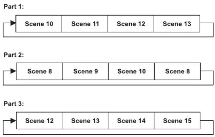
flowchart
graph LR
    A["Scene 10"] --> B["Scene 11"] --> C["Scene 12"] --> D["Scene 13"]
    E["Scene 8"] --> F["Scene 9"] --> G["Scene 10"] --> H["Scene 8"]
    I["Scene 12"] --> J["Scene 13"] --> K["Scene 14"] --> L["Scene 15"]
Fehlermeldungen
Wenn Sie das Gerät einschalten, wird zuerst ein Reset durchgeführt. Wenn auf dem Display eine Fehlermeldung erscheint, gibt es Fehler an einem oder mehreren Kanälen. Die Fehlermeldung steht für den entsprechenden Kanal mit einem Testsensor für die korrekte Position.
Wenn auf dem Display z.B. "Err channel PAN" erscheint, bedeutet dies einen Fehler im Steuerkanal 1: Horizontale Bewegung (PAN). Gibt es gleichzeitig einen Fehler an mehreren Kanälen, blinken die Fehlermeldungen 2-mal im Display, danach führt das Gerät einen Reset durch. Wenn die Fehlermeldungen nach dem Reset noch 2-mal erscheinen, arbeiten nur die Kanäle mit den Fehlern nicht fehlerfrei.
Deutsch
Die entsprechende Fehlermeldung erscheint, wenn nach dem Reset magnetisch-indizierte Fehlfunktionen an dem entsprechenden Kanalfeature vorliegen (Photodiode defekt oder der Magnet fehlt) oder der Steppermotor defekt ist (oder dessen Treiber auf der Hauptplatine). Dabei befindet sich das entsprechende Kanalfeature nach dem Reset nicht in der Vorgabeposition.
Die verschiedenen Fehlermeldungen sind:
PAN Color Wheel Prism Rotation
TILT Static Gobo Wheel Focus
REINIGUNG UND WARTUNG
Der Unternehmer hat dafür zu sorgen, dass sicherheitstechnische und maschinentechnische Einrichtungen mindestens alle vier Jahre durch einen Sachverständigen im Umfang der Abnahmeprüfung geprüft werden.
Der Unternehmer hat dafür zu sorgen, dass sicherheitstechnische und maschinentechnische Einrichtungen mindestens einmal jährlich durch einen Sachkundigen geprüft werden.
Dabei muss unter anderem auf folgende Punkte besonders geachtet werden:
1) Alle Schrauben, mit denen das Gerät oder Geräteteile montiert sind, müssen fest sitzen und dürfen nicht korrodiert sein.
2) An Gehäuse, Befestigungen und Montageort (Decke, Abhängung, Traverse) dürfen keine Verformungen sichtbar sein.
3) Mechanisch bewegte Teile wie Achsen, Ösen u. Ä. dürfen keinerlei Verschleißspuren zeigen (z.B. Materialabrieb oder Beschädigungen) und dürfen sich nicht unwuchtig drehen.
4) Die elektrischen Anschlussleitungen dürfen keinerlei Beschädigungen, Materialalterung (z.B. poröse Leitungen) oder Ablagerungen aufweisen. Weitere, auf den jeweiligen Einsatzort und die Nutzung abgestimmte Vorschriften werden vom sachkundigen Installateur beachtet und Sicherheitsmängel behoben.
LEBENSGEFAHR!
Vor Wartungsarbeiten unbedingt allpolig vom Netz trennen!
Das Gerät sollte regelmäßig von Verunreinigungen wie Staub usw. gereinigt werden. Verwenden Sie zur Reinigung ein fusselfreies, angefeuchtetes Tuch. Auf keinen Fall Alkohol oder irgendwelche Lösungsmittel zur Reinigung verwenden!

ACHTUNG!
Die Linse muss gewechselt werden, wenn diese sichtbar beschädigt ist, so dass ihre Wirksamkeit beeinträchtigt ist, z. B. durch Sprünge oder tiefe Kratzer!
Die Objektivlinse sollte wöchentlich gereinigt werden, da sich sehr schnell Nebelfluidrückstände absetzen, die die Leuchtkraft des Gerätes erheblich reduzieren. Den Lüfter monatlich reinigen.
Reinigen Sie das Innere des Projektors mindestens einmal im Jahr mit einem Staubsauger oder einer Luftbürste.
Im Geräteinneren befinden sich keine zu wartenden Teile.
Wartungs- und Servicearbeiten sind ausschließlich dem autorisierten Fachhandel vorbehalten!
Sicherungswechsel
Wenn die Feinsicherung des Gerätes defekt ist, darf diese nur durch eine Sicherung gleichen Typs ersetzt werden.
Vor dem Sicherungswechsel ist das Gerät allpolig von der Netzspannung zu trennen (Netzstecker ziehen).
Deutsch
Vorgehensweise:
Schritt 1: Drehen Sie den Sicherungshalter an der Geräterückseite mit einem passenden Schraubendreher aus dem Gehäuse (gegen den Uhrzeigersinn).
Schritt 2: Entfernen Sie die defekte Sicherung aus dem Sicherungshalter.
Schritt 3: Setzen Sie die neue Sicherung in den Sicherungshalter ein.
Schritt 4: Setzen Sie den Sicherungshalter wieder im Gehäuse ein und drehen Sie ihn fest.
Sollten einmal Ersatzteile benötigt werden, verwenden Sie bitte nur Originalersatzteile.
Wenn die Anschlussleitung dieses Gerätes beschädigt wird, muss sie durch eine besondere Anschlussleitung ersetzt werden, die von Ihrem Fachhändler erhältlich ist.
Sollten Sie noch weitere Fragen haben, steht Ihnen Ihr Fachhändler jederzeit gerne zur Verfügung.
TECHNISCHE DATEN
| Spannungsversorgung: 100-240 V AC, 50/60 Hz ~ | |
| Gesamtanschlusswert: | 200 |
| DMX-Steuerkanäle: | 11/13/14/17 |
| DMX512-Anschluss: 3-pol. und 5-pol. XLR | |
| Musiksteuerung: über eingebautes Mikrofon | |
| LED-Typ: | Array |
| Anzahl der LEDs: 1 | |
| Abstrahlwinkel: 3° | |
| Farbrad: 14 dichroitische Farben und offen | |
| Statisches Goborad: 17 Gobos und offen | |
| Max. Schwenkbewegung (PAN): 630° | |
| Max. Kippbewegung (TILT): 270° | |
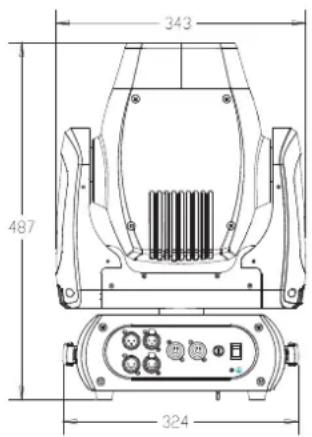
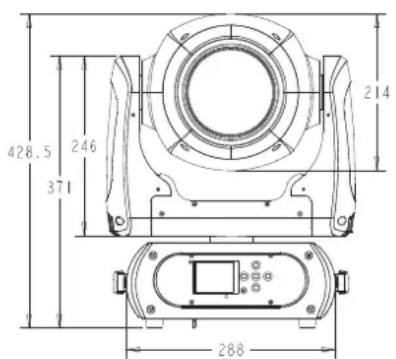
| Maße (LxBxH): 343 x 250 x 428 mm | |
| Gewicht: | 14 |
| Maximale Umgebungstemperatur Ta: | 45°C |
| Maximale Leuchtentemperatur im Beharrungszustand Tc: | 65°C |
| Mindestabstand zu entflammbaren Oberflächen: | 0,5 m |
| Mindestabstand zum angestrahlten Objekt: | 2 m |
| Sicherung: | T 3,15 A, 250 V |
| Zubehör: | |
| FUTURELIGHT WDR-G4 Drahtlos-DMX-Empfänger Einbau | Best.-Nr. 51834021 |
| EUROLITE TPC-10 Klammer, silber | Best.-Nr. 59006856 |
| EUROLITE Sicherungsseil AG-15 4x1000mm bis 15kg | Best.-Nr. 58010364 |
| OMNITRONIC XLR Kabel 5pol 3m sw | Best.-Nr. 30220768 |
| FUTURELIGHT DES-5 Abschlussstecker 5pol | Best.-Nr. 51834002 |
| PSSO PowerCon Verbindungskabel 3x1,5 1,5m | Best.-Nr. 3023503L |
| ROADINGER Flightcase 2x DMH-90/150/DMB-60/PLB-230 | Best.-Nr. 51836892 |
| ROADINGER Flightcase 4x DMH-90/150/DMB-160/PLB-230 | Best.-Nr. 51836894 |
| FUTURELIGHT RDM PC Director USB Interface | Best.-Nr. 51834860 |
KONFORMITÄT
EU-Konformitätserklärung
51841807
Steinigke Showtechnic GmbH
Andreas-Bauer Str. 5
D-97297 Waldbüttelbrunn
Die alleinige Verantwortung für die Ausstellung dieser Konformitätserklärung trägt der Hersteller Steinigke Showtechnic GmbH
FUTURELIGHT DMB-160 LED Moving-Head
Der oben beschriebene Gegenstand der Erklärung erfüllt die Vorschriften der Richtlinie(n):
Richtlinie 2004/108/EG des Europäischen Parlaments und des Rates vom
- Dezember 2004 zur Angleichung der Rechtsvorschriften der Mitgliedstaaten über die elektromagnetische Verträglichkeit und zur Aufhebung der Richtlinie 89/336/EWG
Richtlinie 2006/95/EG des europäischen Parlaments und des Rates vom
- Dezember 2006 zur Angleichung der Rechtsvorschriften der Mitgliedstaaten betreffend elektrische Betriebsmittel zur Verwendung innerhalb bestimmter Spannungsgrenzen (konsolidierte Fassung)
Richtlinie 2011/65/EU des Europäischen Parlaments und des Rates vom
- Juni 2011 zur Beschränkung der Verwendung bestimmter gefährlicher Stoffe in Elektro- und Elektronikgeräten
Richtlinie 1999/5/EG des Europäischen Parlaments und des Rates vom
- März 1999 über Funkanlagen und Telekommunikationsendeinrichtungen und die gegenseitige Anerkennung ihrer Konformität
Auszug berücksichtigter Normen:
EMV: EN 55015:2013, EN 61547:2009
EN 301489-1 V1.9.2, EN 301489-9 V1.4.1
LVD: EN 60598-1:2008 + A11:2009; EN 60598-2-17:1989 + A2:1991
RoHS: EN 50581:2012
R&TTE: EN 300328 V1.8.1
Unterzeichnet für und im Namen der Steinigke Showtechnic GmbH
Waldbüttelbrunn, den 22.09.2014
Klaus Schuster
(Techn. Betriebsleiter)
USER MANUAL
Futurelight®
DMB-160 LED Moving Head
CAUTION!
Keep this device away from rain and moisture! Never open the housing!
For your own safety, please read this user manual carefully before you initially start-up.
Every person involved with the installation, operation and maintenance of this device has to
- be qualified
- follow the instructions of this manual
- consider this manual to be part of the total product
- keep this manual for the entire service life of the product
- pass this manual on to every further owner or user of the product
- download the latest version of the user manual from the Internet
INTRODUCTION
Thank you for having chosen a FUTURELIGHT DMB-160. You will see you have acquired a powerful and versatile device.
Unpack your DMB-160.
Delivery includes
Device
User manual
Omega holder with quick-lock fastener
DMX cable 3 m
PowerCon power supply cable 1.5 m
SAFETY INSTRUCTIONS
CAUTION!
Be careful with your operations. With a dangerous voltage you can suffer a dangerous electric shock when touching the wires!
English
This device has left our premises in absolutely perfect condition. In order to maintain this condition and to ensure a safe operation, it is absolutely necessary for the user to follow the safety instructions and warning notes written in this user manual.

Important:
Damages caused by the disregard of this user manual are not subject to warranty. The dealer will not accept liability for any resulting defects or problems.
If the device has been exposed to drastic temperature fluctuation (e.g. after transportation), do not switch it on immediately. The arising condensation water might damage your device. Leave the device switched off until it has reached room temperature.
Please make sure that there are no obvious transport damages. Should you notice any damages on the A/C connection cable or on the casing, do not take the device into operation and immediately consult your local dealer.
This device falls under protection-class I. The power plug must only be plugged into a protection class I outlet. The voltage and frequency must exactly be the same as stated on the device. Wrong voltages or power outlets can lead to the destruction of the device and to mortal electrical shock.
Always plug in the power plug last. The power plug must always be inserted without force. Make sure that the plug is tightly connected with the outlet.
Never let the power-cord come into contact with other cables! Handle the power-cord and all connections with the mains with particular caution! Never touch them with wet hands, as this could lead to mortal electrical shock.
Never modify, bend, strain mechanically, put pressure on, pull or heat up the power cord. Never operate next to sources of heat or cold. Disregard can lead to power cord damages, fire or mortal electrical shock.
The cable insert or the female part in the device must never be strained. There must always be sufficient cable to the device. Otherwise, the cable may be damaged which may lead to mortal damage.
Make sure that the power-cord is never crimped or damaged by sharp edges. Check the device and the power-cord from time to time.
If extension cords are used, make sure that the core diameter is sufficient for the required power consumption of the device. All warnings concerning the power cords are also valid for possible extension cords.
Always disconnect from the mains, when the device is not in use or before cleaning it. Only handle the power-cord by the plug. Never pull out the plug by tugging the power-cord. Otherwise, the cable or plug can be damaged leading to mortal electrical shock. If the power plug or the power switch is not accessible, the device must be disconnected via the mains.
If the power plug or the device is dusty, the device must be taken out of operation, disconnected and then be cleaned with a dry cloth. Dust can reduce the insulation which may lead to mortal electrical shock. More severe dirt in and at the device should only be removed by a specialist.
There must never enter any liquid into power outlets, extension cords or any holes in the housing of the device. If you suppose that also a minimal amount of liquid may have entered the device, it must immediately be disconnected. This is also valid, if the device was exposed to high humidity. Also if the device is still running, the device must be checked by a specialist if the liquid has reduced any insulation. Reduced insulation can cause mortal electrical shock.
There must never be any objects entering into the device. This is especially valid for metal parts. If any metal parts like staples or coarse metal chips enter into the device, the device must be taken out of operation and disconnected immediately. Malfunction or short-circuits caused by metal parts may cause mortal injuries.

HEALTH HAZARD!
Never look directly into the light source, as sensitive persons may suffer an epileptic shock (especially meant for epileptics)!

CAUTION!
The light beam generates an extreme amount of heat. Please ensure, therefore, that the beam does not shine on only one particular point for an extended period of time!
Keep away children and amateurs!
Never leave this device running unattended.
OPERATING DETERMINATIONS
This device is a LED moving-head lighting effect for creating decorative effects. This product is only allowed to be operated with an alternating voltage of 100-240 V, 50/60 Hz and was designed for indoor use only.
This device is designed for professional use, e.g. on stages, in discotheques, theatres etc.
Lighting effects are not designed for permanent operation. Consistent operation breaks will ensure that the device will serve you for a long time without defects.
Do not shake the device. Avoid brute force when installing or operating the device.
Never lift the fixture by holding it at the projector-head, as the mechanics may be damaged. Always hold the fixture at the transport handles.
When choosing the installation-spot, please make sure that the device is not exposed to extreme heat, moisture or dust. There should not be any cables lying around. Please make sure that the unit cannot be touched or bumped. You endanger your own and the safety of others!
This device must never be operated or stockpiled in surroundings where splash water, rain, moisture or fog may harm the device. Moisture or very high humidity can reduce the insulation and lead to mortal electrical shocks. When using smoke machines, make sure that the device is never exposed to the direct smoke jet and is installed in a distance of 0.5 meters between smoke machine and device. The room must only be saturated with an amount of smoke that the visibility will always be more than 10 meters.
The ambient temperature must always be between -5^ C and +45^ C. Keep away from direct insulation (particularly in cars) and heaters.
The relative humidity must not exceed 50 % with an ambient temperature of 45^ C.
This device must only be operated in an altitude between -20 and 2000 m over NN.
Never use the device during thunderstorms. Over voltage could destroy the device. Always disconnect the device during thunderstorms.
The symbol ·s m determines the minimum distance from lighted objects. The minimum distance between light-output and the illuminated surface must be more than this value.
The device must only be installed on a non-flammable surface. In order to safeguard sufficient ventilation, leave 50 cm of free space around the device.
The housing must never touch surrounding surfaces or objects.
Make sure that the area below the installation place is blocked when rigging, derigging or servicing the fixture.
English
For overhead use (mounting height >100 cm), always fix the fixture with an appropriate safety-rope. Fix the safety-rope at the correct fixation points only. The safety-rope must never be fixed at the transport handles!
Only operate the fixture after having checked that the housing is firmly closed and all screws are tightly fastened.
The maximum ambient temperature T_a = 45^ C must never be exceeded.
Operate the device only after having become familiarized with its functions. Do not permit operation by persons not qualified for operating the device. Most damages are the result of unprofessional operation!
Please use the original packaging if the device is to be transported.
Please consider that unauthorized modifications on the device are forbidden due to safety reasons!
Never remove the serial barcode from the device as this would make the guarantee void.
If this device will be operated in any way different to the one described in this manual, the product may suffer damages and the guarantee becomes void. Furthermore, any other operation may lead to dangers like short-circuit, burns, electric shock, crash etc.
WEEE Directive

When to be definitively put out of operation, take the unit(s) to a local recycling plant for a disposal which is not harmful to the environment. Do not dispose of as municipal waste. Contact your retailer or local authorities for more information.
DESCRIPTION OF THE DEVICE
Features
LED Beam with 150 W COB LED and the advantages of a Moving-Head
- With glass lens
• Extremely high light output
• Very narrow illumination angle of 3^ - Upgrade via optional wireless receiver module for WDMX operation (Wireless Solution - made in Sweden)
- Flicker-free projection
• Supports RDM (Remote Device Management)
• 11, 13, 14 or 17 DMX channels selectable - Effect wheel with rotating 6 fold linear prism, 8-facet prism and frost
• Color wheel with 14 different dichroic color filters plus white - Rainbow effect with adjustable speed in both directions
• Gobo wheel with 17 static gobos plus open - With gobo shake function
- Exact positioning via 16 bit PAN/TILT movement resolution
- Dimmer
- Motorized focus
- Strobe effect with adjustable speed
- Random strobe effect
• Automatic position correction - PAN angle switchable between 540^ and 630^
• Sound-controlled via built-in microphone - Switch-mode power supply for operation between 100 and 240 Volts
- ESDC function (Easy Service Data Check) with battery-buffered control board for operation time readouts etc. (the Li-Ion battery 3.7V, AAA, 10440 is not included)
- Control board with graphic LCD and foil-keyboard for adjusting the DMX-starting address, PAN/TILT reverse, reset
- DMX-controlled operation or stand-alone operation with Master/Slave function
- The scenes can be modified via the Control Board or via an external controller and loaded into the memory
• Number of scenes can be changed individually - Software upload by optional accessories via DMX link
- Power connection via Neutrik PowerCon jack and included power cable
- Feed-through output allows to power up to 8 devices
- DMX control via any standard DMX controller
English
Overview
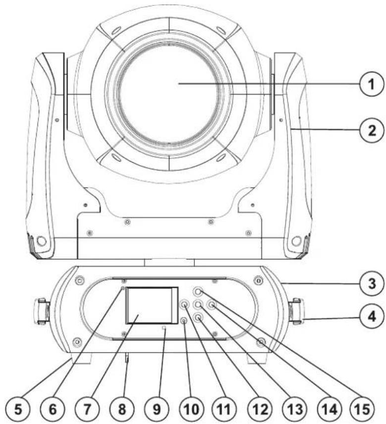
(1) Objective lens
(2) Yoke
(3) Base
(4) Carrying handle
(5) Rubber foot
(6) Wireless indicator
(7) Display
(8) Safety eyelet
(9) Microphone
(10) ESDC switch
(11) Arrow button left
(12) Arrow button down
(13) Enter button
(14) Arrow button right
(15) Arrow button up
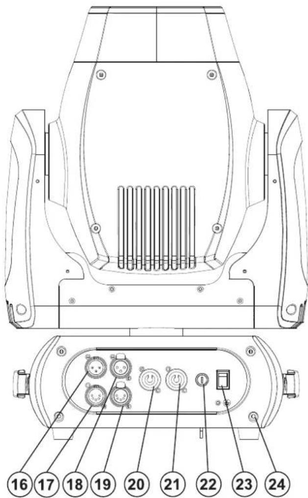
(16) 3-PIN DMX input plug
(17) 5-PIN DMX input plug
(18) 3-PIN DMX output socket
(19) 5-PIN DMX output socket
(20) Power input
(21) Power output
(22) Fuseholder
(23) Power switch
(24) Housing screw
INSTALLATION
Rigging

DANGER TO LIFE!
Please consider the EN 60598-2-17 and the respective national norms during the installation! The installation must only be carried out by an authorized dealer!
The installation of the projector has to be built and constructed in a way that it can hold 10 times the weight for 1 hour without any harming deformation.
The installation must always be secured with a secondary safety attachment, e.g. an appropriate catch net. This secondary safety attachment must be constructed in a way that no part of the installation can fall down if the main attachment fails.
When rigging, derigging or servicing the fixture staying in the area below the installation place, on bridges, under high working places and other endangered areas is forbidden.
The operator has to make sure that safety-relating and machine-technical installations are approved by an expert before taking into operation for the first time and after changes before taking into operation another time.
The operator has to make sure that safety-relating and machine-technical installations are approved by an expert after every four year in the course of an acceptance test.
The operator has to make sure that safety-relating and machine-technical installations are approved by a skilled person once a year.
Procedure:
The projector should be installed outside areas where persons may walk by or be seated.
IMPORTANT! OVERHEAD RIGGING REQUIRES EXTENSIVE EXPERIENCE, including (but not limited to) calculating working load limits, installation material being used, and periodic safety inspection of all installation material and the projector. If you lack these qualifications, do not attempt the installation yourself, but instead use a professional structural rigger. Improper installation can result in bodily injury and or damage to property.
The projector has to be installed out of the reach of people.
If the projector shall be lowered from the ceiling or high joists, professional trussing systems have to be used. The projector must never be fixed swinging freely in the room.
Caution: Projectors may cause severe injuries when crashing down! If you have doubts concerning the safety of a possible installation, do NOT install the projector!
Before rigging make sure that the installation area can hold a minimum point load of 10 times the projector's weight.

DANGER OF FIRE!
When installing the device, make sure there is no highly-inflammable material (decoration articles, etc.) within a distance of min. 0.5 m.
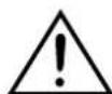
CAUTION!
Use an appropriate clamp to rig the fixture on the truss. Follow the instructions mentioned at the bottom of the base. Make sure that the device is fixed properly! Ensure that the structure (truss) to which you are attaching the fixtures is secure.
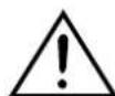
English
natural_image
Technical line drawing of a mechanical frame structure with no text or symbolsThe fixture's base enables to be mounted in two ways.
The Moving-Head can be placed directly on the stage floor or rigged in any orientation on a truss without altering its operation characteristics (see the drawing).
Make sure that the Omega-holder is always in line with the truss structure when installing the device vertically.
For overhead use (mounting height >100 cm), always install an appropriate safety bond.
You must only use safety bonds and quick links complying with DIN 56927, shackles complying with DIN EN 1677-1 and BGV C1 carbines. The safety bonds, quick links, shackles and the carbines must be sufficiently dimensioned and used correctly
in accordance with the latest industrial safety regulations (e. g. BGV C1, BGI 810-3).
Please note: for overhead rigging in public or industrial areas, a series of safety instructions have to be followed that this manual can only give in part. The operator must therefore inform himself on the current safety instructions and consider them.
The manufacturer cannot be made liable for damages caused by incorrect installations or insufficient safety precautions!
Install the safety bond by inserting the quick link in the hole on the bottom of the base. Pull the safety bond over the trussing system etc. Insert the end in the quick link and tighten the fixation screw.
The maximum drop distance must never exceed 20 cm.
A safety bond which already hold the strain of a crash or which is defective must not be used again.
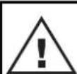
DANGER TO LIFE!
Before taking into operation for the first time, the installation has to be approved by an expert!
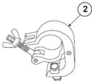
natural_image
Technical line drawing of a mechanical clamp or bracket component (no text or symbols)(1) Omega-holder
(2) Clamp
(3) Safety-rope
(4) Quick-lock fastener
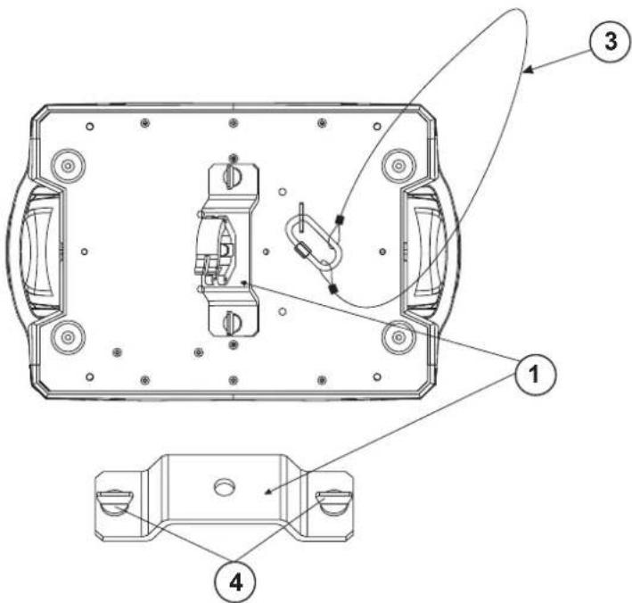
English
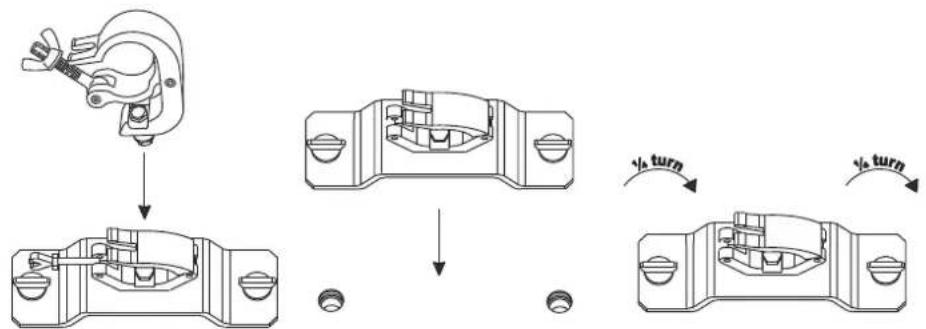
flowchart
graph TD
    A["Initial Component"] --> B["Step 1: Rotation"]
    B --> C["Step 2: Rotation"]
    C --> D["Step 3: Rotation"]
    D --> E["Final Component with Rotation Arrow indicating √h turn"]
Screw the clamp via a M10 screw and self locking nut onto the Omega-holder.
Insert the quick-lock fasteners of the Omega-holder into the respective holes on the bottom of the device. Tighten the quick-lock fasteners fully clockwise.
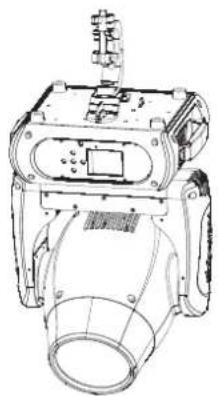
natural_image
Technical line drawing of a mechanical device with no visible text or symbolsInstallation of the optional wireless receiver for WDMX-operation (FUTURELIGHT WDR-G4)
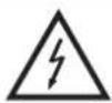
CAUTION! Prior to installation, disconnect the device from the mains. Risk of electric shock!
Installation steps
- Remove the wireless DMX receiver from the packaging. The module consists of a threaded rod antenna, a wireless PCB and a connecting cable.
- Remove the four screws from the control board on the front panel and carefully open the control board cover, laying it face down. On the left side of the display board you will find two connectors for the wireless DMX receiver.
- First screw the rod antenna onto the antenna jack then place the antenna along the display board, in the control board cover.
- To attach the wireless PCB, loosen the three screws on the display board and remove them. Insert the plug contacts of the wireless module into the socket on the display board and screw the three screws on again. Insert the plug of the connecting cable into the designated socket.
- Carefully replace the control board cover onto the control board and tighten the four screws on the front panel.
A
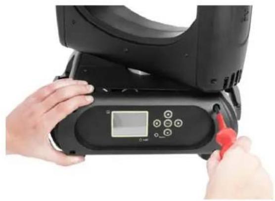
natural_image
Close-up of hands operating a black electronic device with a digital display and red tool (no visible text or symbols)B
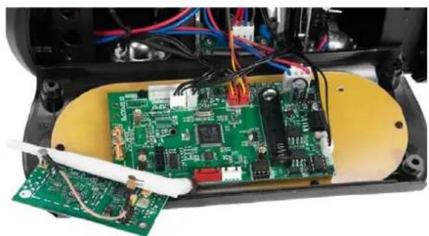
natural_image
Interior view of an electronic device showing a green circuit board with exposed components and wiring (no visible text or symbols)C
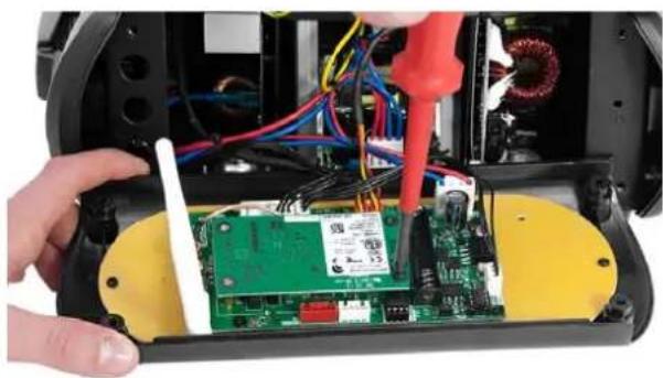
natural_image
Close-up of hands installing or repairing a green circuit board with multicolored wires and a red tool (no visible text or symbols)D
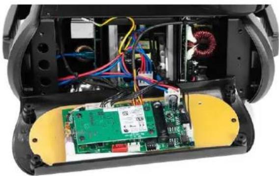
natural_image
Interior view of a robotic device showing exposed circuit board, wiring, and motor coil (no text or symbols visible)DMX-512 connection / connection between fixtures
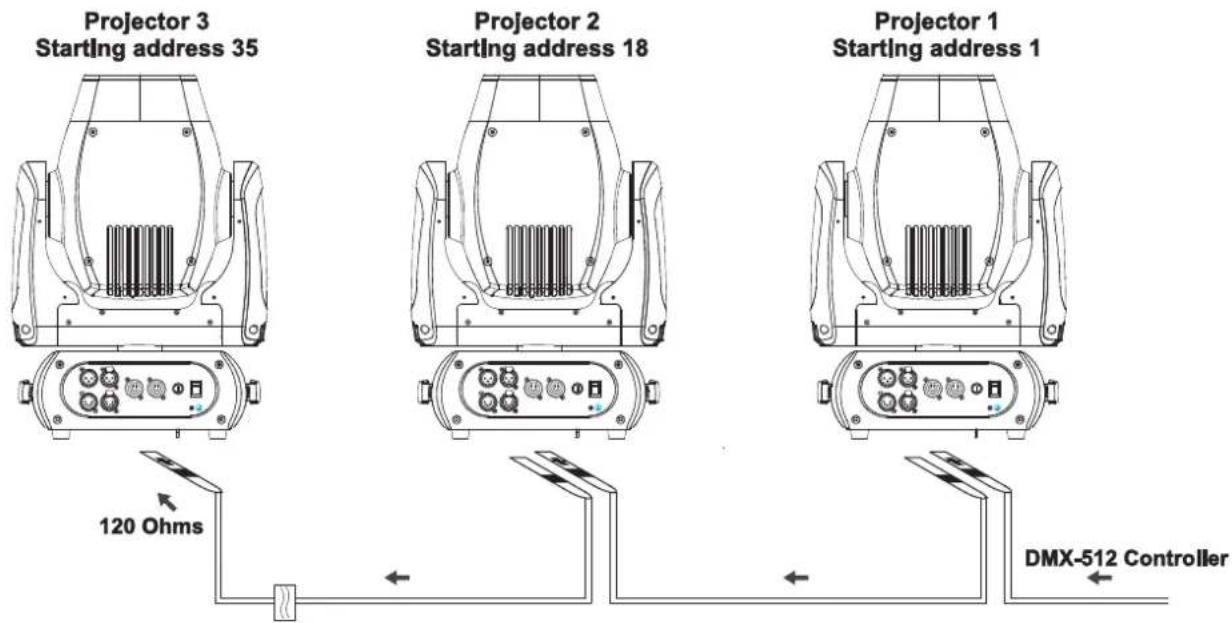
The wires must not come into contact with each other, otherwise the fixtures will not work at all, or will not work properly.

Please note, the starting address depends upon which controller is being used.
Only use a DMX-cable and 3-pin, or 5-pin, XLR-plugs and connectors in order to connect the controller with the fixture or one fixture with another.
Occupation of the XLR-connection:
DMX-output
XLR mounting-socket:
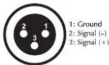
DMX-input
XLR mounting-plug:
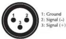
DMX-output
XLR mounting-socket:
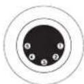
1: Ground
2: Signal (−)
3: Signal (+)
4: NC
5: NC
DMX-input
XLR mounting-plug:
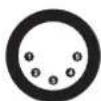
1: Ground
2: Signal (−)
3: Signal (+)
4: NC
5: NC
If you are using controllers with this occupation, you can connect the DMX-output of the controller directly with the DMX-input of the first fixture in the DMX-chain. If you wish to connect DMX-controllers with other XLR-outputs, you need to use adapter-cables.
Building a serial DMX-chain:
Connect the DMX-output of the first fixture in the DMX-chain with the DMX-input of the next fixture. Always connect one output with the input of the next fixture until all fixtures are connected. Not suitable as signal splitter!
Caution: At the last fixture, the DMX-cable has to be terminated. Plug the terminator with a 120 Ω resistor between Signal (−) and Signal (+) in the DMX-output of the last fixture.
English
Connection with the mains
Connect the device to the mains with the enclosed power supply cable.
The occupation of the connection-cables is as follows:
| Cable | Pin | International |
| Brown | Live | L |
| Blue | Neutral | N |
| Yellow/Green | Earth |
The earth has to be connected!
If the device will be directly connected with the local power supply network, a disconnection switch with a minimum opening of 3 mm at every pole has to be included in the permanent electrical installation.
The device must only be connected with an electric installation carried out in compliance with the IEC-standards. The electric installation must be equipped with a Residual Current Device (RCD) with a maximum fault current of 30 mA.
Lighting effects must not be connected to dimming-packs.
The device is equipped with a lockable power input connector. Plug in the power cord and turn it to the right until it locks. Plug the power cord into a grounded electrical outlet that matches the rated voltage of the machine.
On the rear panel, there is a socket (Power Out). Connect the output with the mains input of the next fixture until all fixtures are connected.
Please note: A maximum of 8 devices may be linked together. After every 8 devices, the fixtures must have a renewed connection with the power mains.
OPERATION
With the power switch, you can switch the device on and off.
After you connected the effect to the mains, the DMB-160 starts running. During the Reset, the motors are trimmed and the device is ready for use afterwards.
Stand Alone operation
In the Stand Alone mode, the DMB-160 can be used without controller. Disconnect the DMB-160 from the controller and call the internal program. Please refer to the instructions under Control Board.
DMX-controlled operation
You can control the projectors individually via your DMX-controller. Every DMX-channel has a different occupation with different features. The individual channels and their features are listed under DMX-protocol.
Addressing
The Control Board allows you to assign the DMX starting address, which is defined as the first channel from which the DMB-160 will respond to the controller.
If you set, for example, the address in the 17 channel mode to channel 18, the DMB-160 will use the channel 18 to 34 for control.
Please, be sure that you don't have any overlapping channels in order to control each DMB-160 correctly and independently from any other fixture on the DMX-chain.
English
If several DMB-160 are addressed similarly, they will work synchronically.
Press the Up/Down-buttons for setting the desired starting address. Now you can start operating the DMB-160 via your lighting controller.
Note:
After switching on, the device will automatically detect whether DMX 512 data is received or not. If there is no data received at the DMX-input, the display will flash.
This situation can occur if:
- the XLR plug (cable with DMX signal from controller) is not connected with the input of the device.
- the controller is switched off or defective, if the cable or connector is defective or the signal wires are swap in the input connector.
Note:
It's necessary to insert the XLR termination plug (with 120 Ohm) in the last lighting in the link in order to ensure proper transmission on the DMX data link.
DMX-protocol
| Mode/Channel | Decimal | Hexad. | Percentage | S/F | Feature | ||||||
| St. | Ex. | Basic 8bit | Basic 16bit | ||||||||
| 1 | 1 | 1 | Horizontal movement (PAN) | ||||||||
| 10 | 255 | 00 | FF | 0% | 100% | F | Push slider up in order to move the head horizontally (PAN). Gradual head adjustment from one end of the slider to the other (0-255, 128-center). The head can be stopped at any position you wish. | ||||
| 2 | 2 | PAN-movement with 16-bit resolution | |||||||||
| 0 | 255 | 00 | FF | 0% | 100% | F | Fine indexing | ||||
| 2 | 3 | 2 | Vertical movement (Tilt) | ||||||||
| 30 | 255 | 00 | FF | 0% | 100% | F | Push slider up in order to move the head vertically (TILT). Gradual head adjustment from one end of the slider to the other (0-255, 128-center). The head can be stopped at any position you wish. | ||||
| 4 | 4 | TILT-movement with 16-bit resolution | |||||||||
| 0 | 255 | 00 | FF | 0% | 100% | F | Fine indexing | ||||
| 3 | 5 | 3 | 5 | PAN/TILT speed | |||||||
| 0 | 255 | 00 | FF | 0% | 100% | F | Decreasing speed | ||||
| 6 | PAN/TILT function | ||||||||||
| 0 | 15 | 00 | 0F | 0% | 6% | S | Normal | ||||
| 16 | 31 | 10 | 1F | 6% | 12% | S | Blackout at PAN/TILT-movement | ||||
| 32 | 255 | 20 | FF | 13% | 100% | S | No function | ||||
| 4 | 7 | Shutter, strobe function | |||||||||
| 0 | 15 | 00 | 0F | 0% | 6% | S | Normal Shutter Functions | ||||
| 16 | 31 | 10 | 1F | 6% | 12% | S | Opening pulse-effect | ||||
| 32 | 47 | 20 | 2F | 13% | 18% | S | Closing pulse-effect | ||||
| 48 | 63 | 30 | 3F | 19% | 25% | S | Random strobe-effect | ||||
| 64 | 255 | 40 | FF | 25% | 100% | S | No function | ||||
English
| 5 | 8 | Shutter, strobe | |||||||||
| Normal Shutter Functions | |||||||||||
| 0 | 31 | 00 | 1F | 0% | 12%S | Close | |||||
| 32 | 223 | 20 | DF | 13% | 87% | F | Strobe-effect with increasing speed | ||||
| 224 | 255 | E0 | FF | 88% | 100% | S | Open | ||||
| Opening pulse-effect | |||||||||||
| 0 | 31 | 00 | 1F | 0% | 12%S | Close | |||||
| 32 | 223 | 20 | DF | 13% | 87% | F | Pulse-effect with increasing speed | ||||
| 224 | 255 | E0 | FF | 88% | 100% | S | Open | ||||
| Closing pulse-effect | |||||||||||
| 0 | 31 | 00 | 1F | 0% | 12%S | Close | |||||
| 32 | 223 | 20 | DF | 13% | 87% | F | Pulse-effect with increasing speed | ||||
| 224 | 255 | E0 | FF | 88% | 100% | S | Open | ||||
| Random strobe-effect | |||||||||||
| 0 | 31 | 00 | 1F | 0% | 12%S | Close | |||||
| 32 | 223 | 20 | DF | 13% | 87% | F | Strobe-effect with increasing speed | ||||
| 224 | 255 | E0 | FF | 88% | 100% | S | Open | ||||
| 4 | 6 | Shutter, strobe | |||||||||
| 0 | 31 | 00 | 1F | 0% | 12%S | S | Shutter closed | ||||
| 32 | 63 | 20 | 3F | 13% | 25%S | S | No function (shutter open) | ||||
| 64 | 95 | 40 | 5F | 25% | 37%S | F | Strobe-effect with increasing speed | ||||
| 96 | 127 | 60 | 7F | 38% | 50%S | S | No function (shutter open) | ||||
| 128 | 159 | 80 | 9F | 50% | 62%S | F | Pulse-effect in sequences | ||||
| 160 | 191 | A0 | BF | 63% | 75%S | S | No function (shutter open) | ||||
| 192 | 223 | C0 | DF | 75% | 87%S | F | Random strobe-effect with increasing speed | ||||
| 224 | 255 | E0 | FF | 88% | 100%S | S | No function (shutter open) | ||||
| 6 | 9 | 5 | 7 | Dimmer intensity | |||||||
| 0 | 255 | 00 | FF | 0% | 100%S | F | Gradual adjustment of the dimmer intensity from 0 to 100 % | ||||
| 7 | 10 | Color function | |||||||||
| 0 | 15 | 00 | 0F | 0% | 6%S | Normal color-change | |||||
| 16 | 31 | 10 | 1F | 6% | 12%S | Blackout at color-change | |||||
| 32 | 47 | 20 | 2F | 13% | 18%S | S | Forwards rainbow effect | ||||
| 48 | 63 | 30 | 3F | 19% | 25%S | S | Backwards rainbow effect | ||||
| 64 | 79 | 40 | 4F | 25% | 31%S | S | Color-change at every position | ||||
| 80 | 111 | 50 | 6F | 31% | 44%S | S | Color Bounce | ||||
| 112 | 255 | 70 | FF | 44% | 100%S | S | No function | ||||
| 8 | 11 | Color-wheel | |||||||||
| Normal color-change / Blackout at color-change | |||||||||||
| 0 | 16 | 00 | 10 | 0% | 6%S | S | Open | ||||
| 17 | 33 | 11 | 21 | 7% | 13%S | S | Position 1 | ||||
| 34 | 50 | 22 | 32 | 13% | 20%S | S | Position 2 | ||||
| 51 | 67 | 33 | 43 | 20% | 26%S | S | Position 3 | ||||
| 68 | 84 | 44 | 54 | 27% | 33%S | S | Position 4 | ||||
| 85 | 101 | 55 | 65 | 33% | 40%S | S | Position 5 | ||||
| 102 | 118 | 66 | 76 | 40% | 46%S | S | Position 6 | ||||
English
| 119 | 135 | 77 | 87 | 47% | 53% | S | Position 7 | ||||
| 136 | 152 | 88 | 98 | 53% | 60% | S | Position 8 | ||||
| 153 | 169 | 99 | A9 | 60% | 66% | S | Position 9 | ||||
| 170 | 186 | AA | BA | 67% 73% | S | Position 10 | |||||
| 187 | 203 | BB | CB | 73% 80% | S | Position 11 | |||||
| 204 | 220 | CC | DC | 80% 86% | S | Position 12 | |||||
| 221 | 237 | DD | ED | 87% 93% | S | Position 13 | |||||
| 238 | 255 | EE | FF | 93% | 100% | S | Position 14 | ||||
| Forwards rainbow effect | |||||||||||
| 0 | 255 | 00 | FF | 0% | 100% | F | With increasing speed | ||||
| Backwards rainbow effect | |||||||||||
| 0 | 255 | 00 | FF | 0% | 100% | F | With increasing speed | ||||
| Color-change at every position | |||||||||||
| 0 | 255 | 00 | FF | 0% | 100% | F | Positioning from 0 - 360 degrees | ||||
| Color Bounce | |||||||||||
| 0 | 8 | 00 | 08 | 0% | 3% | S | Open | ||||
| 9 | 17 | 09 | 11 | 4% | 7% | S | Position 1 | ||||
| 18 | 26 | 12 | 1A | 7% | 10% | S | Position 2 | ||||
| 27 | 35 | 1B | 23 | 11% | 14% | S | Position 3 | ||||
| 36 | 44 | 24 | 2C | 14% | 17% | S | Position 4 | ||||
| 45 | 53 | 2D | 35 | 18% | 21% | S | Position 5 | ||||
| 54 | 62 | 36 | 3E | 21% | 24% | S | Position 6 | ||||
| 63 | 71 | 3F | 47 | 25% | 28% | S | Position 7 | ||||
| 72 | 80 | 48 | 50 | 28% | 31% | S | Position 8 | ||||
| 81 | 89 | 51 | 59 | 32% | 35% | S | Position 9 | ||||
| 90 | 98 | 5A | 62 | 35% | 38% | S | Position 10 | ||||
| 99 | 107 | 63 | 6B | 39% | 42% | S | Position 11 | ||||
| 108 | 116 | 6C | 74 | 42% | 45% | S | Position 12 | ||||
| 117 | 125 | 75 | 7D | 46% 49% | S | Position 13 | |||||
| 126 | 134 | 7E | 86 | 49% | 53% | S | Position 14 | ||||
| 135 | 143 | 87 | 8F | 53% | 56% | S | Position 15 | ||||
| 144 | 152 | 90 | 98 | 56% | 60% | S | Position 16 | ||||
| 153 | 161 | 99 | A1 | 60% | 63% | S | Position 17 | ||||
| 162 | 170 | A2 | AA | 64% 67% | S | Position 18 | |||||
| 171 | 179 | AB | B3 | 67% | 70% | S | Position 19 | ||||
| 180 | 188 | B4 | BC | 71% | 74% | S | Position 20 | ||||
| 189 | 197 | BD | C5 | 74% 77% | S | Position 21 | |||||
| 198 | 206 | C6 | CE | 78% 81% | S | Position 22 | |||||
| 207 | 215 | CF | D7 | 81% 84% | S | Position 23 | |||||
| 216 | 224 | D8 | E0 | 85% | 88% | S | Position 24 | ||||
| 225 | 233 | E1 | E9 | 88% | 91% | S | Position 25 | ||||
| 234 | 242 | EA | F2 | 92% | 95% | S | Position 26 | ||||
| 243 | 251 | F3 | FB | 95% | 98% | S | Position 27 | ||||
| 252 | 255 | FC | FF | 99% | 100% | S | Position 28 | ||||
| Color-wheel | |||||||
| Normal color-change | |||||||
| 0 2 | 00 | 02 | 0% | 1% | S | Open | |
| 3 5 | 03 | 05 | 1% | 2% | S | Position 1 | |
| 6 8 | 06 | 08 | 2% | 3% | S | Position 2 | |
| 9 11 | 09 | 0B | 4% | 4% | S | Position 3 | |
| 12 14 | 0C | 0E | 5% | 5% | S | Position 4 | |
| 15 17 | 0F | 11 | 6% | 7% | S | Position 5 | |
| 18 20 | 12 | 14 | 7% | 8% | S | Position 6 | |
| 21 23 | 15 | 17 | 8% | 9% | S | Position 7 | |
| 24 26 | 18 | 1A | 9% | 10% | S | Position 8 | |
| 27 | 29 | 1B | 1D | 11% | 11% | S | Position 9 |
| 30 | 32 | 1E | 20 | 12% | 13% | S | Position 10 |
| 33 | 35 | 21 | 23 | 13% | 14% | S | Position 11 |
| 36 | 38 | 24 | 26 | 14% | 15% | S | Position 12 |
| 39 | 41 | 27 | 29 | 15% | 16% | S | Position 13 |
| 42 | 44 | 2A | 2C | 16% | 17% | S | Position 14 |
| Blackout at color-change | |||||||
| 45 | 47 | 2D | 2F | 18% | 18% | S | Open |
| 48 | 50 | 30 | 32 | 19% | 20% | S | Position 1 |
| 51 | 53 | 33 | 35 | 20% | 21% | S | Position 2 |
| 54 | 56 | 36 | 38 | 21% | 22% | S | Position 3 |
| 57 | 59 | 39 | 3B | 22% | 23% | S | Position 4 |
| 60 | 62 | 3C | 3E | 24% | 24% | S | Position 5 |
| 63 | 65 | 3F | 41 | 25% | 25% | S | Position 6 |
| 66 | 68 | 42 | 44 | 26% | 27% | S | Position 7 |
| 69 | 71 | 45 | 47 | 27% | 28% | S | Position 8 |
| 72 | 74 | 48 | 4A | 28% | 29% | S | Position 9 |
| 75 | 77 | 4B | 4D | 29% | 30% | S | Position 10 |
| 78 | 80 | 4E | 50 | 31% | 31% | S | Position 11 |
| 81 | 83 | 51 | 53 | 32% | 33% | S | Position 12 |
| 84 | 86 | 54 | 56 | 33% | 34% | S | Position 13 |
| 87 | 89 | 57 | 59 | 34% | 35% | S | Position 14 |
| Color Bounce | |||||||
| 90 | 98 | 5A | 62 | 35% | 38% | F | Open |
| 99 | 107 | 63 | 6B | 39% | 42% | F | Position 1 |
| 108 | 116 | 6C | 74 | 42% | 45% | F | Position 2 |
| 117 | 125 | 75 | 7D | 46% | 49% | F | Position 3 |
| 126 | 134 | 7E | 86 | 49% | 53% | F | Position 4 |
| 135 | 143 | 87 | 8F | 53% | 56% | F | Position 5 |
| 144 | 152 | 90 | 98 | 56% | 60% | F | Position 6 |
| 153 | 161 | 99 | A1 | 60% | 63% | F | Position 7 |
| 162 | 170 | A2 | AA | 64% | 67% | F | Position 8 |
| 171 | 179 | AB | B3 | 67% | 70% | F | Position 9 |
| 180 | 188 | B4 | BC | 71% | 74% | F | Position 10 |
| 189 | 197 | BD | C5 | 74% | 77% | F | Position 11 |
| 198 | 206 | C6 | CE | 78% | 81% | F | Position 12 |
| 207 | 215 | CF | D7 | 81% | 84% | F | Position 13 |
| 216 | 223 | D8 | DF | 85% | 87% | F | Position 14 |
| Forwards rainbow effect | |||||||
| 224 | 239 | E0 | EF | 88% | 94% | F | With increasing speed |
| Backwards rainbow effect | |||||||
| 240 | 255 | F0 | FF | 94% | 100% | F | With increasing speed |
English
| 9 | 12 | Static gobo-wheel, gobo-shake function | |||||||||
| 0 | 15 | 00 | 0F | 0% | 6% | S | Normal gobo-change | ||||
| 16 | 31 | 10 | 1F | 6% | 12% | S | Blackout at gobo-change | ||||
| 32 | 47 | 20 | 2F | 13% | 18% | S | Rotating gobo-wheel forwards | ||||
| 48 | 63 | 30 | 3F | 19% | 25% | S | Rotating gobo-wheel backwards | ||||
| 64 | 79 | 40 | 4F | 25% | 31% | S | Gobo-change at every position | ||||
| 80 | 95 | 50 | 5F | 31% | 37% | S | Gobo-shake | ||||
| 96 | 255 | 60 | FF | 38% | 100% | S | No function | ||||
| 10 | 13 | Static gobo-wheel, gobo-shake | |||||||||
| Normal gobo-change / Blackout at gobo-change / gobo-shake | |||||||||||
| 0 | 13 | 00 | 0D | 0% | 5% | S/F | Open | ||||
| 14 | 27 | 0E | 1B | 5% | 11% | S/F | Position 1 | ||||
| 28 | 41 | 1C | 29 | 11% | 16% | S/F | Position 2 | ||||
| 42 | 55 | 2A | 37 | 16% | 22% | S/F | Position 3 | ||||
| 56 | 69 | 38 | 45 | 22% | 27% | S/F | Position 4 | ||||
| 70 | 83 | 46 | 53 | 27% | 33% | S/F | Position 5 | ||||
| 84 | 97 | 54 | 61 | 33% | 38% | S/F | Position 6 | ||||
| 98 | 111 | 62 | 6F | 38% | 44% | S/F | Position 7 | ||||
| 112 | 125 | 70 | 7D | 44% | 49% | S/F | Position 8 | ||||
| 126 | 139 | 7E | 8B | 49% | 55% | S/F | Position 9 | ||||
| 140 | 153 | 8C | 99 | 55% | 60% | S/F | Position 10 | ||||
| 154 | 167 | 9A | A7 | 60% | 65% | S/F | Position 11 | ||||
| 168 | 181 | A8 | B5 | 66% | 71% | S/F | Position 12 | ||||
| 182 | 195 | B6 | C3 | 71% | 76% | S/F | Position 13 | ||||
| 196 | 209 | C4 | D1 | 77% | 82% | S/F | Position 14 | ||||
| 210 | 223 | D2 | DF | 82% | 87% | S/F | Position 15 | ||||
| 224 | 237 | E0 | ED | 88% | 93% | S/F | Position 16 | ||||
| 238 | 255 | EE | FF | 93% | 100% | S/F | Position 17 | ||||
| Rotating gobo-wheel forwards | |||||||||||
| 0 | 255 | 00 | FF | 0% | 100% | F | With increasing speed | ||||
| Rotating gobo-wheel backwards | |||||||||||
| 0 | 255 | 00 | FF | 0% | 100% | F | With increasing speed | ||||
| Gobo-change at every position | |||||||||||
| 0 | 255 | 00 | FF | 0% | 100% | F | Positioning from 0 - 360 degrees | ||||
| 7 | 9 | Static gobo-wheel, gobo-shake | |||||||||
| Normal gobo-change | |||||||||||
| 0 | 1 | 00 | 01 | 0% | 0% | S | Open | ||||
| 2 | 3 | 02 | 03 | 1% | 1% | S | Position 1 | ||||
| 4 | 5 | 04 | 05 | 2% | 2% | S | Position 2 | ||||
| 6 | 7 | 06 | 07 | 2% | 3% | S | Position 3 | ||||
| 8 | 9 | 08 | 09 | 3% | 4% | S | Position 4 | ||||
| 10 | 11 | 0A | 0B | 4% | 4% | S | Position 5 | ||||
| 12 | 13 | 0C | 0D | 5% | 5% | S | Position 6 | ||||
English
| 14 | 15 | 0E | 0F | 5% | 6% | S | Position 7 | |
| 16 | 17 | 10 | 11 | 6% | 7% | S | Position 8 | |
| 18 | 19 | 12 | 13 | 7% | 7% | S | Position 9 | |
| 20 | 21 | 14 | 15 | 8% | 8% | S | Position 10 | |
| 22 | 23 | 16 | 17 | 9% | 9% | S | Position 11 | |
| 24 | 25 | 18 | 19 | 9% | 10% | S | Position 12 | |
| 26 | 27 | 1A | 1B | 10% | 11% | S | Position 13 | |
| 28 | 29 | 1C | 1D | 11% | 11% | S | Position 14 | |
| 30 | 31 | 1E | 1F | 12% | 12% | S | Position 15 | |
| 32 | 33 | 20 | 21 | 13% | 13% | S | Position 16 | |
| 34 | 35 | 22 | 23 | 13% | 14% | S | Position 17 | |
| Blackout at gobo-change | ||||||||
| 36 | 37 | 24 | 25 | 14% | 15% | S | Open | |
| 38 | 39 | 26 | 27 | 15% | 15% | S | Position 1 | |
| 40 | 41 | 28 | 29 | 16% | 16% | S | Position 2 | |
| 42 | 43 | 2A | 2B | 16% | 17% | S | Position 3 | |
| 44 | 45 | 2C | 2D | 17% | 18% | S | Position 4 | |
| 46 | 47 | 2E | 2F | 18% | 18% | S | Position 5 | |
| 48 | 49 | 30 | 31 | 19% | 19% | S | Position 6 | |
| 50 | 51 | 32 | 33 | 20% | 20% | S | Position 7 | |
| 52 | 53 | 34 | 35 | 20% | 21% | S | Position 8 | |
| 54 | 55 | 36 | 37 | 21% | 22% | S | Position 9 | |
| 56 | 57 | 38 | 39 | 22% | 22% | S | Position 10 | |
| 58 | 59 | 3A | 3B | 23% | 23% | S | Position 11 | |
| 60 | 61 | 3C | 3D | 24% | 24% | S | Position 12 | |
| 62 | 63 | 3E | 3F | 24% | 25% | S | Position 13 | |
| 64 | 65 | 40 | 41 | 25% | 25% | S | Position 14 | |
| 66 | 67 | 42 | 43 | 26% | 26% | S | Position 15 | |
| 68 | 69 | 44 | 45 | 27% | 27% | S | Position 16 | |
| 70 | 71 | 46 | 47 | 27% | 28% | S | Position 17 | |
| Gobo-shake | ||||||||
| 72 | 80 | 48 | 50 | 28% | 31% | F | Position 1 | |
| 81 | 89 | 51 | 59 | 32% | 35% | F | Position 2 | |
| 90 | 98 | 5A | 62 | 35% | 38% | F | Position 3 | |
| 99 | 107 | 63 | 6B | 39% | 42% | F | Position 4 | |
| 108 | 116 | 6C | 74 | 42% | 45% | F | Position 5 | |
| 117 | 125 | 75 | 7D | 46% | 49% | F | Position 6 | |
| 126 | 134 | 7E | 86 | 49% | 53% | F | Position 7 | |
| 135 | 143 | 87 | 8F | 53% | 56% | F | Position 8 | |
| 144 | 152 | 90 | 98 | 56% | 60% | F | Position 9 | |
| 153 | 161 | 99 | A1 | 60% | 63% | F | Position 10 | |
| 162 | 170 | A2 | AA | 64% | 67% | F | Position 11 | |
| 171 | 179 | AB | B3 | 67% | 70% | F | Position 12 | |
| 180 | 188 | B4 | BC | 71% | 74% | F | Position 13 | |
English
| 189 | 197 | BD | C5 | 74% 77% F | Position 14 | ||||||
| 198 | 206 | C6 | CE | 78% 81% F | Position 15 | ||||||
| 207 | 215 | CF | D7 | 81% 84% F | Position 16 | ||||||
| 216 | 223 | D8 | DF | 85% 87% F | Position 17 | ||||||
| Rotating gobo-wheel forwards | |||||||||||
| 224 | 224 | E0 | E0 | 88% | 88% | S | Stop | ||||
| 225 | 239 | E1 | EF | 88% 94% F | With increasing speed | ||||||
| Rotating gobo-wheel backwards | |||||||||||
| 240 | 240 | F0 | F0 | 94% | 94% | S | Stop | ||||
| 241 | 255 | F1 | FF | 95% | 100% | F | With increasing speed | ||||
| 11 | 14 | 8 | 10 | Prism | |||||||
| 0 | 63 | 00 | 3F | 0% | 25% | S | Open | ||||
| 64 | 127 | 40 | 7F | 25% | 50% | S | 6 fold linear prism | ||||
| 128 | 191 | 80 | BF | 50% 75% S | 8 facet prism | ||||||
| 192 | 255 | C0 | FF | 75% | 100% | S | Frost | ||||
| 12 | 15 | 9 | 11 | Prism rotation | |||||||
| Prism rotation at every position | |||||||||||
| 0 | 191 | 00 | BF | 0% | 75% | F | Positioning from 0 - 360 degrees | ||||
| Rotating prism forwards | |||||||||||
| 192 | 223 | C0 | DF | 75% 87% F | With increasing speed (stop to fastest speed) | ||||||
| Rotating prism backwards | |||||||||||
| 224 | 255 | E0 | FF | 88% | 100% | F | With increasing speed (stop to fastest speed) | ||||
| 13 | 16 | 10 | 12 | Focus | |||||||
| 0 | 255 | 00 | FF | 0% | 100% | F | Continuous adjustment from near to far | ||||
| 14 | 17 | 11 | 13 | Reset, display control | |||||||
| 0 | 7 | 00 | 07 | 0% | 3% | S | No function | ||||
| 8 | 15 | 08 | 0F | 3% | 6% | S | Reset all motors | ||||
| 16 | 23 | 10 | 17 | 6% | 9% | S | Reset only Pan/Tilt | ||||
| 24 | 31 | 18 | 1F | 9% 12% | S | Reset only colors | |||||
| 32 | 39 | 20 | 27 | 13% | 15% | S | Reset only gobo | ||||
| 40 | 47 | 28 | 2F | 16% | 18% | S | No function | ||||
| 48 | 55 | 30 | 37 | 19% | 22% | S | Reset other motors | ||||
| 56 | 63 | 38 | 3F | 22% | 25% | S | Display Off | ||||
| 64 | 71 | 40 | 47 | 25% | 28% | S | Display On | ||||
| 72 | 79 | 48 | 4F | 28% | 31% | S | No function | ||||
| 80 | 87 | 50 | 57 | 31% | 34% | S | No function | ||||
| 88 | 95 | 58 | 5F | 35% | 37% | S | Hibernation | ||||
| 96 | 255 | 60 | FF | 38% | 100% | S | No function | ||||
Control Board
The Control Board offers several features: you can simply set the starting address, run the pre-programmed program or make a reset.
The main menu is accessed by pressing Enter until the display is lit. Browse through the menu by pressing the arrow buttons (up, down, left, right). Press Enter in order to select the desired menu. You can change the selection by pressing the arrow buttons. Press Enter in order to confirm. The functions provided are described in the following sections.
Default settings shaded. ① Basic Reload / ② Program Reload / ③ Private Reload
| Main | menu Sub menu | Display Function | ||
| Connect | DMX Address 1 | DMX address setting | ||
| Wireless 1 | Wireless DMX (optional equipment) | |||
| Light | Max Temperature 1 | 80-139°C,90°C/176-282°F,194°F | LED off at temperature | |
| Lamp Adjust | PAN ... | Service | function | |
| Information | Time info | Current | XXXX | Power on running time |
| Fixture Life XXXX (h) Fixture running time | ||||
| Temperature Near Lamp Temp. ... XXX °C/°F Inside temperature | ||||
| Fans Speed | Near Lamp Fan | Fan speed | ||
| Channel Value | PAN ... | PAN = XXX ... | DMX indicator | |
| Error Message | PAN, TILT ... | Error channels | ||
| Fixture Model | xxxxxxxxxxx | Model number and brand | ||
| Software Ver | 1U01 V 1.0.002U01 V 1.0.00 ... | Software version of each IC | ||
| Set | Reset | All | Reset all motors | |
| PAN&TILT | Reset only PAN/TILT | |||
| Colors | Reset colors | |||
| Gobos | Reset gobos | |||
| Others | Reset other motors | |||
| Movement 1 | PAN reverse | ON/OFF | Reverse movement | |
| TILT reverse | ON/OFF | |||
| PAN degree | 630/540 | Select PAN-angle 630° or 540° | ||
| Encoders ON/OFF | Automatic PAN/TILT calibration | |||
| PAN/TILT Mode | Stand/Smooth | Adjust PAN/TILT speed | ||
| UI Set | Mic Sens 3 | 0~99%, 60% | Mic sensitivity | |
| No Signal 1 | Close/Hold/Auto/Music | Run if no DMX | ||
| Temperature C/F 1 | Celsius/Fahrenheit | Select temperature designation °C or °F | ||
| Fans Mode 1 | Auto Speed/High Speed | Fans mode select | ||
| Hibernation 1 | OFF, 01M-99M, 15M | Standby mode | ||
| Backlight 1 | 02M-60M, 02M | Display shutoff time | ||
| Flip Display 1 | ON/OFF | Display reverse 180 degree | ||
| Display Bright 3 | 00-31 10 | Display Brightness | ||
| Brand Show 1 | ON/OFF | Show brand name | ||
| Key Lock 1 | ON/OFF | Key lock activation | ||
| Language 3 | En/简/繁/Fr/Sp | Language select | ||
| Set | Users | User Mode 1 | StandardExtendedBasic-8bitBasic-16bitUser | User's mode to change channel numbers |
| Edit User 3 | Max Channel = XXPAN = CH01 ... | Preset User modes | ||
| Calibration 3 | --Password--Color ... | Password=XXXColor =XXX ... | Wheel adjustment to standard position password „050“ | |
| Fixture ID 3 | Name--Password--PID Code | Namepassword „050Set PID Code of RDM | ||
| Wireless Set 3 | DMX on cableReset Connect | ON/OFFON/OFF | Loopthrough dataLogout from sender (optional equipment) | |
| Reload Default | Basic Reload 1Program Reload 2--Password--Private Reload 3All Reload | ON/OFFON/OFFXXXON/OFFON/OFF | Basic ReloadProgram Reload password „050“Private ReloadAll Reload | |
| Program | Play 1 | DMX receive | Back to DMX mode | |
| Slave receive | Slave 1, Slave 2, Slave 3 | Slave setting | ||
| Sequence | Master/Alone | Auto program | ||
| Music | Master/Alone | Music control | ||
| Select Chase 2 | Chase Part 1Chase Part 2Chase Part 3 | Chase 1-8 Chase 1Chase 1-8 Chase 2Chase 1-8 Chase 3 | Select programs to be run | |
| Edit Chase 2 | Chase 1:Chase 8 | Chase TestStep 01 = SCXXXStep 64 = SCXXX | Testing programProgram in loopSave and exit | |
| Edit Scenes 2 | Edit scene 001:Edit scene 250 | Pan,Tilt, ...-- Fade Time --Scene Time --DMX Input | Save and automatically return manual scenes edit | |
| Scenes Record ScXX=>ScXX Automat. scenes rec | ||||
Connect
DMX address setting
With this function, you can adjust the desired DMX-address via the Control Board.
- Select "DMX Address" by pressing Up or Down.
- Press the Enter-button, adjust the DMX address by pressing Up or Down.
- Press the Enter-button to confirm.
Wireless
From factory, this projector is prepared for wireless data transmission (W-DMX).
With the function "Wireless" you can log in the wireless receiver in to a wireless transmitter, the fixture could now receive the wireless DMX signal.
- Select "Wireless" by pressing Up or Down.
- Press the Enter-button to confirm.
If a device with wireless receiver is connected with a DMX-controller via cable, the device will be controlled by the cabled controller and not by the wireless transmitter.
English
Light
Max Temperature
With this function you can set the inside temperature at which the projector will automatically switch the LED off. Press Up or Down to select the maximum inside temperature between 80 °C and 139 °C. Inside temperatures below 90 °C are not critical. 90 °C and more should lead to the LED being switched off. Please note that the outside temperature should not exceed 45 °C.
Information
Time information
Current
With this function, you can display the temporary running time of the device from the last power on. The display shows "XXXX", "X" stands for the number of hours. The counter is reset after turning the device off.
Fixture Life
With this function, you can display the running time of the device. The display shows "XXXX", "X" stands for the number of hours.
Temperature
Near lamp Temp
With this function you can display the temperature in the projector-head (near CMY-filter) in degree Celsius/degree Fahrenheit.
...
Fan speed
With this function you can display the current fan speed. The display shows "XXXX", "X" stands for RPM.
DMX indicator
With this function, you can display with which value the respective channel is sent.
Error channels
With this function, you can display the channel errors.
Fixture Model
With this function, you can display the model number and brand of the fixture.
Software version
With this function you can display the software version of each IC.
- Select "Software ver." by pressing Up or Down.
- Press the Enter-button, the display shows e.g. "1U01 VX.X.XX", "X.X.XX" stands for the version number.
Set
Reset
With this function you can reset the device via the Control Board. You can select the different Reset-functions by pressing Up or Down.
Movement
PAN Reverse
With this function you can reverse the PAN-movement.
TILT Reverse
With this function you can reverse the TILT-movement.
PAN degree
With this function you can select the PAN-degree.
- Select "PAN degree" by pressing Up or Down.
- Press the Enter-button, the display shows "540".
- Press Up or Down to select the desired degree between "540" and "630".
- Press the Enter-button to confirm.
English
Automatic PAN/TILT calibration
With the function "Encoders" you can calibrate the PAN/TILT movement to the correct starting position.
Adjust PAN/TILT speed
With this function you can define the PAN/TILT speed. You can select one of two different modes.
UI Set
Mic sensitivity
With this function, you can select the desired microphone sensitivity between 0 % and 99 %.
- Select "Mic Sens" by pressing Up or Down.
- Press the Enter-button.
- Press Up or Down to select the desired sensitivity.
- Press the Enter-button to confirm.
No DMX status
With the function "No Signal", you can set different modes if there is no DMX-signal.
- Select "Close, Hold, Auto or Music" by pressing Up or Down.
- Press Up or Down to select between "Close", "Hold", "Auto" or "Music".
- Press the Enter-button to confirm.
Select temperature designation
With this function you can select the temperature designation.
- Select "Temperature C/F" by pressing Up or Down.
- Press Up or Down to select the desired degree between "Celsius" and "Fahrenheit".
- Press the Enter-button to confirm.
Adjust ventilation fans mode
With this function, you can adjust the ventilation fans mode.
- Select "Fans Mode" by pressing Up or Down.
- Press Enter to confirm; the display shows "Auto Speed".
- Press Up or Down to select "Auto Speed" or "High Speed".
- Press the Enter-button to confirm.
Hibernation - power standby mode
With this function you can put the device in the power standby mode. This function will be automatically activated after a predefined period of time of no DMX activity. In standby mode the lamp/LEDs and all motors will power down if no DMX signal is sent to the fixture for a period of e. g. 15 minutes (can be user defined). The fixture will automatically reset and return to normal operation once a DMX signal is sent.
Backlight
With this function you can shut off the display after 2 to 60 minutes.
Flip Display
With this function you can flip the display by 180^ for a better view when the fixture is hung from the truss or a ceiling.
Display Bright
With this function, you can select the desired display brightness.
Brand Show
With this function you can show or hide the brand name 'FUTURELIGHT' on the display.
Key lock
With this function you can lock the keys of the Control Board to e.g. prevent menu tampering. If this function is activated, the keys will be automatically locked from the last command. In order to deactivate or temporarily deactivate the key lock function, press the keys in the following order: ↑ UP, ↓ DOWN, ← LEFT, → RIGHT and ENTER to regain access to the menu commands.
Language select
With this function, you can select the desired display language.
Users
User mode
With this function, you can create user defined channel orders.
English
Edit User
With this function, you can adjust the preset user definition.
Calibration
With this function, you can calibrate and adjust the effect wheels to their correct positions. The password for this function is „050“.
Fixture ID
RDM
With this function you can call up various submenus via RDM.
This device is RDM ready. RDM stands for "Remote Device Management" and makes remote control of devices connected to the DMX-bus possible. ANSI E1.20-2006 by ESTA specifies the RDM standard as an extension of the DMX512 protocol.
Manual settings like adjusting the DMX starting address are no longer needed. This is especially useful when the device is installed in a remote area.
RDM is integrated in DMX without influencing the connections. The RDM-data is transmitted via the standard XLR-poles 1 and 2 – new DMX-cables are not necessary. RDM ready and conventional DMX devices can be operated in one DMX line. The RDM protocol sends own packages in the DMX512 data feed and does not influence conventional devices.
If DMX splitters are used and RDM control is to be used, these splitters must support RDM.
The number and type of RDM parameters depend on the (optional) RDM controller being used.
Wireless Set
With the function "DMX on cable", you can loopthrough the DMX signal via DMX cable and with the function "Reset Connect", you can log out the projector from the wireless sender.
Reload Default
With this function you can restore the factory settings of the device. The different settings (marked in the table) will be set back to the default values (shaded).
Program
Play
DMX Receive
With this function, you can set the device to the DMX mode.
Slave Receive
With this function, you can define the device as slave. You can choose one of three different Slave programs. For further information see „Edit Chase”.
Sequence
With this function, you can run the internal program. You can select the desired program under "Select Chase". You can set the number of steps under "Edit Chase". You can edit the individual scenes under "Edit Scenes". With this function, you can run the individual scenes either automatically, i.e. with the adjusted Step-Time. The selection "Alone" means Stand Alone-mode and "Master" that the device is defined as master.
Music
With this function, you can run the internal program sound-controlled. The selection "Alone" means Stand Alone-mode and "Master" that the device is defined as master.
Select chase for auto program
With this function, you can select the program for the Program Run.
Edit chase
With this function, you can edit the internal programs.
English
Edit scenes
With this function, you can edit the scenes of the internal programs.
Rec. Controller
The device features an integrated DMX-recorder by which you can transmit the programmed scenes from your DMX-controller to the device. Adjust the desired scene numbers by pressing Up or Down (from – to). When you call up the scenes at your controller, they will automatically be transmitted to the device.
Excursion:
A Master unit can send up to 3 different data groups to the Slave units, i.e. a Master unit can start 3 different Slave units, which run 3 different programs. The Master unit sends the 3 program parts in a continuous loop. The Slave unit receives data from the Master unit according to the group which the Slave unit was assigned to. If e.g. a Slave unit is set to „Slave 1“ in the menu „Set to Slave“, the Master unit sends „Auto Program Part 1“ to the Slave unit. If set to „Slave 2“, the Slave unit receives „Chase Part 2“.
To start a Auto Program please proceed as follows:
1.Slave-Setting
- Select "Program" by pressing Up or Down.
- Press the Enter-button to confirm.
- Select "Slave" by pressing Up or Down.
- Press the Enter-button to confirm.
- Press Up or Down to select "Slave 1", "Slave 2" or "Slave 3".
- Press the Enter-button to confirm.
2. Automatic Program Run
- Select "Program" by pressing Up or Down.
- Press the Enter-button to confirm.
- Select "Sequence" by pressing Up or Down.
- Press the Enter-button to confirm.
- Press Up or Down to select "Master" or "Alone". The selection "Alone" means Stand Alone-mode and
"Master" that the device is defined as master. - Press the Enter-button to confirm.
3. Program for Select Chase
- Select "Edit Chase" by pressing Up or Down.
- Press the Enter-button to confirm.
- Select "Select Chase" by pressing Up or Down.
- Press the Enter-button to confirm.
- Press Up or Down to select “Chase Part 1”, “Chase Part 2” or “Chase Part 3”, and thus select which Slave program is to be sent. Selection „Part 1“ means, that the Slave unit runs the same program as the master units.
- Press the Enter-button to confirm.
4. Program selection for Edit Program
- Select "Edit Chase" by pressing Up or Down.
- Press the Enter-button to confirm.
- Select "Edit Chase" by pressing Up or Down.
- Press the Enter-button to confirm.
- Press Up or Down to select the desired program. With this function you can edit specific scenes into a specific program.
- Press the Enter-button to confirm.
5. Automatic Scene Recording
- Select "Edit Chase" by pressing Up or Down.
- Press the Enter-button to confirm.
- Select "Edit scenes" by pressing Up or Down.
- Press the Enter-button to confirm.
- Press Up or Down to select the desired scene numbers. You can program a maximum number of 250 scenes.
- Press the Enter-button to confirm.
- Press Up or Down to select the desired value.
- Press the Enter-button to confirm.
English
Example:
Program 2 includes scenes: 10, 11, 12, 13;
Program 4 includes scenes: 8, 9, 10 and
Program 6 includes scenes: 12, 13, 14, 15, 16
Chase Part 1 is Program 2;
Chase Part 2 is Program 3;
Chase Part 3 is Program 6
The 3 Slave groups run the Auto Program in certain time segments, as shown in the following picture:
Part 1:
| Scene 10 | Scene 11 | Scene 12 | Scene 13 |
Part 2:
| Scene 8 | Scene 9 | Scene 10 | Scene 8 |
Part 3:
| Scene 12 | Scene 13 | Scene 14 | Scene 15 |
Error Messages
When you turn on the fixture, it will make a reset first. The display may show an error message while there are problems with one or more channels. The error message stands for the channels equipped with a testing sensor.
For example, when the display shows “Err channel PAN”, it means there is some error in the horizontal movement (PAN), control-channel 1. If there are some errors on several channels at the same time, you may see the error messages flash repeatedly for 2 times, and then the fixture will generate a reset signal, all the stepper motors will reset. If the error messages maintain after performing reset more than 2 times, only the channels which have errors can not work properly, others can work as usual.
The respective error message will appear after the reset of the fixture if the channels magnetic-indexing circuit malfunction (sensor failed or magnet missing) or the stepping-motor is defective (or its driving IC on the main PCB). The channel feature is not located in the default position after the reset.
The different error messages are:
PAN Color Wheel Prism Rotation
TILT Static Gobo Wheel Focus
CLEANING AND MAINTENANCE
The operator has to make sure that safety-relating and machine-technical installations are inspected by an expert after every four years in the course of an acceptance test.
The operator has to make sure that safety-relating and machine-technical installations are inspected by a skilled person once a year.
The following points have to be considered during the inspection:
1) All screws used for installing the devices or parts of the device have to be tightly connected and must not be corroded.
2) There must not be any deformations on housings, fixations and installation spots (ceiling, suspension, trussing).
3) Mechanically moved parts like axles, eyes and others must not show any traces of wearing (e.g. material abrading or damages) and must not rotate with unbalances.
4) The electric power supply cables must not show any damages, material fatigue (e.g. porous cables) or sediments. Further instructions depending on the installation spot and usage have to be adhered by a skilled installer and any safety problems have to be removed.
DANGER TO LIFE!
Disconnect from mains before starting maintenance operation!
We recommend a frequent cleaning of the device. Please use a moist, lint-free cloth. Never use alcohol or solvents!

CAUTION!
The lens has to be replaced when it is obviously damaged, so that its function is impaired, e. g. due to cracks or deep scratches!
The objective lens will require weekly cleaning as smoke-fluid tends to building up residues, reducing the light-output very quickly. The cooling-fans should be cleaned monthly.
The interior of the fixture should be cleaned at least annually using a vacuum-cleaner or an air-jet.
There are no serviceable parts inside the device. Maintenance and service operations are only to be carried out by authorized dealers.
Replacing the fuse
If the fine-wire fuse of the device fuses, only replace the fuse by a fuse of same type and rating.
Before replacing the fuse, unplug mains lead.
Procedure:
Step 1: Unscrew the fuseholder on the rearpanel with a fitting screwdriver from the housing (anti-clockwise).
Step 2: Remove the old fuse from the fuseholder.
Step 3: Install the new fuse in the fuseholder.
Step 4: Replace the fuseholder in the housing and fix it.
Should you need any spare parts, please use genuine parts.
If the power supply cable of this device becomes damaged, it has to be replaced by a special power supply cable available at your dealer.
Should you have further questions, please contact your dealer.
TECHNICAL SPECIFICATIONS
| Power supply: 100-240 V AC, 50/60 Hz ~ | |
| Power consumption: 200 W | |
| DMX control channels: 11/13/14/17 | |
| DMX512 connection: 3-pin and 5-pin XLR | |
| Sound-control: via built-in microphone | |
| Type of LEDs: Array 150 W | |
| Number of LEDs: 1 | |
| Beam angle: 3° | |
| Color-wheel: 14 dichroic filters plus open | |
| Static gobo-wheel: 17 gobos and open | |
| Maximum PAN-movement: 630° | |
| Maximum TILT-movement: 270° | |
| Dimensions (LxWxH): 343 x 250 x 428 mm | |
| Weight: | 14 |
| Maximum ambient temperature T_a : | 45°C |
| Maximum housing temperature T_c (steady state): | 65°C |
| Min.distance from flammable surfaces: 0.5 m | |
| Min.distance to lighted object: | 2 m |
| Fuse: | T 3.15 A, 250 V |
| Accessory: | |
| FUTURELIGHT WDR-G4 wireless DMX receiver PCB | No. 51834021 |
| EUROLITE TPC-10 Coupler, silver | No. 59006856 |
| EUROLITE Safety bond AG-15 4x1000mm up to 15kg | No. 58010364 |
| OMNITRONIC XLR cable 5pin 3m bk | No. 30220768 |
| FUTURELIGHT DES-5 DMX terminator 5-pin | No. 51834002 |
| PSSO PowerCon connection cable 3x1.5 1.5m | No. 3023503L |
| ROADINGER Flightcase 2x DMH-90/150/DMB-60/PLB-230 | No. 51836892 |
| ROADINGER Flightcase 4x DMH-90/150/DMB-160/PLB-230 | No. 51836894 |
| FUTURELIGHT RDM PC Director USB Interface | No. 51834860 |
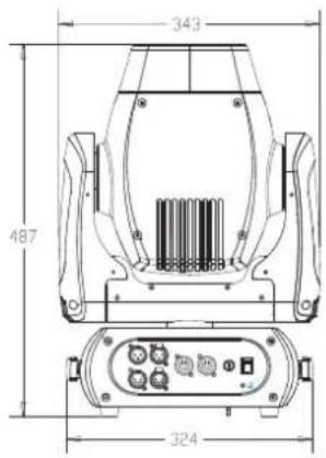
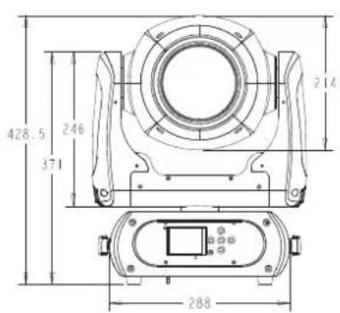
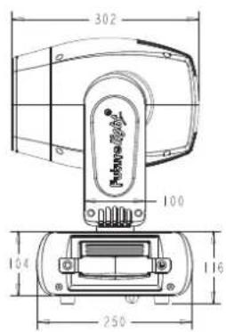
Please note: All information is subject to change without prior notice. 13.05.2016 ©