MODE D'EMPLOI TALENT WHIRLPOOL

WHIRLPOOL AUSTRALIA
CUSTOMER SERVICE
Service Manual
Microwave Ovens
VIP27 Series
CONTENTS
Page
INTRODUCTION 3-4
GENERAL OPERATING INSTRUCTIONS 5-8
CONTROL PANELS 9-10
NEW FEATURES/IMPROVEMENTS 11-12
DESCRIPTION AND FUNCTION OF COMPONENTS 13
ASSEMBLY AND DISASSEMBLY 14-17
MEASUREMENTS AND ADJUSTMENTS 18-19
R.F.LEAKAGE 20
COMPONENTS CHECK
MAGNETRON 21
CAPACITOR 22
DIODE 23
SAFETY SWITCHES 23
23
INTRODUCTION
GENERALITY
The new microwave series VIP 27 are named AVM for Whirlpool and MCI, MCCD, MDID for Bauknecht. The following description is valid for all Whirlpool types.
- Dual Microwave feed
- Turntable
- Stainless steel cooking compartment
- Jet (Rapid) start
- Crisp plate
SECURITY
Use of special tools such as TORX screwdrivers and leakage measuring instruments. Follow the rules below:
BEFORE REPAIR
- Pull out the mains plug and switch off the mains switch of the appliance.
DURING REPAIR
Take care that all internal connections are made correctly
- All wirings are insulated and do not contact the door of the appliance, the housing or the sharp edges.
- All earth connections are electrically and mechanically in perfect order.
- Do not modify or anyway interfere with the safety devices built-in to the oven.
- All spare parts comply with the manufacturer's specification.
CAUTION MICROWAVE RADIATION
PERSONNEL SHOULD NOT BE EXPOSED TO THE MICROWAVE ENERGY, WHICH MAY RADIATE FROM THE MAGNETRON, WAVEGUIDE OR ANTENNA IF THEY ARE IMPROPERLY USED OR CONNECTED. ALL INPUT AND OUTPUT MICROWAVE CONNECTIONS, WAVEGUIDES, FLANGES AND GASKETS MUST BE SECURE.
NEVER OPERATE THE DEVICE WITHOUT A MICROWAVE ENERGY ABSORBING LOAD ATTACHED. NEVER LOOK INTO AN OPEN WAVEGUIDE OR ANTENNA WHILE THE DEVICE IS ENERGIZED.
NEVER OPERATE AN OVEN WITH A CABINET OFF WITHOUT MEASURING THE MICROWAVE LEAKAGE AROUND MAGNETRON AND VISIBLE MICROWAVE CONNECTIONS (WELDING JOINTS).
Do not operate the oven if the following conditions exist:
The door does not close firmly against the door support because the door is warped, or the hinges are damaged.
The door trim or seals are damaged.
If there is any visible damage to the oven.
If the door does not close properly.
Avoid operation the oven if known components in the interlock system, oven door or microwave generating assembly are known defective. They must be replaced.
WARNING - HIGH VOLTAGE
IT IS POSSIBLE TO COME IN CONTACT WITH LETHAL HIGH VOLTAGE WHEN WORKING WITH HVTRANSFORMER, HV CAPACITOR AND MAGNETRON. THEREFORE NEVER TRY TO MEASURE THE HIGH VOLTAGE. ALWAYS TAKE UTMOST CARE WHEN PERFORMING THE ELECTRIC MEASUREMENTS INSIDE THE OVEN.
GENERAL OPERATING INSTRUCTIONS
INSTALLATION INSTRUCTION
Put up the appliance on a stable and straight surface. Never install it near by sources of heat. The ambient air must not exceed a temperature of 35 degrees Celsius. To ensure a sufficient ventilation keep a minimum space of 3cm around the appliance.
FUNCTIONS OF ELECTRONIC AND MECHANICAL MODELS
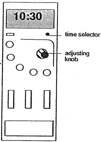
Adjustment of time
Control panel of electronic model
- Press the time selector Both figures are flashing on the left.
- Screw the adjusting knob to the right or left until the required number of hours appears.
- Press the time selector. Both figures are flashing on the right.
- Turn the adjusting knob to the right until the required number of minutes appears.
- Press again the knob for time; afterwards the clock is running.
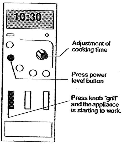
Adjustment of microwave electronic models
mechanical models
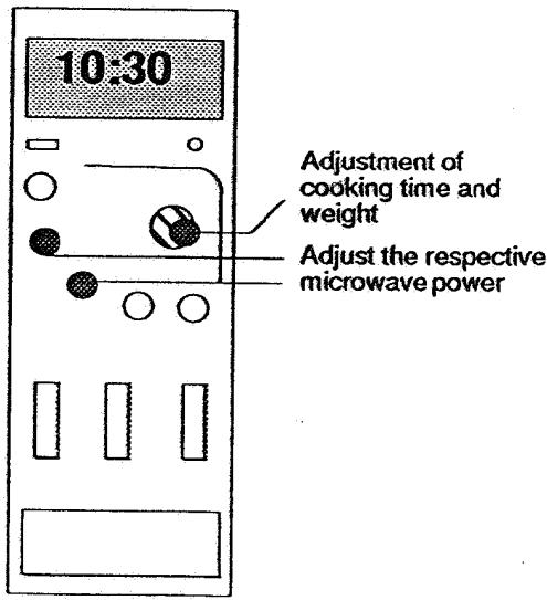
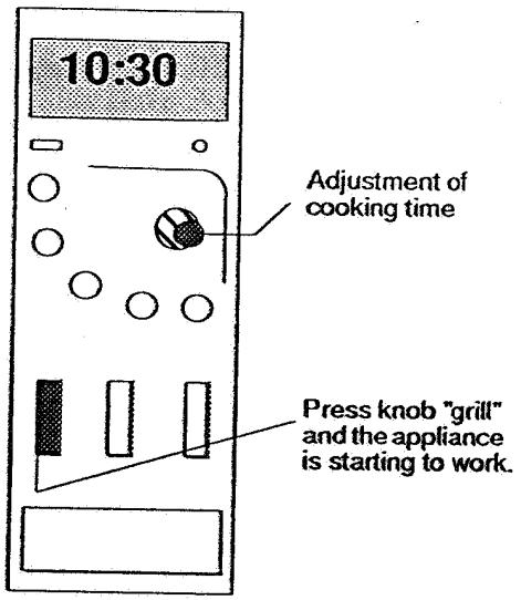
Adjustment of the grill electronic model
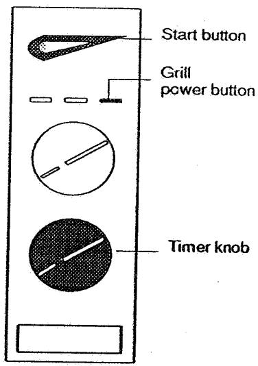
mechanical model
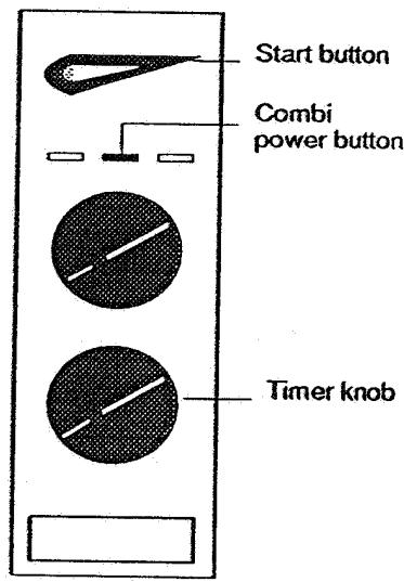
Combined grill and microwave
Jet setting, automatic defrost, Crisp-Grill setting
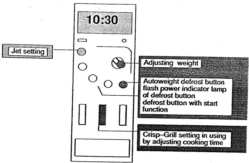
Jet setting / Manual time setting
Jet setting
- The Jet knob is pressed once.
- The Jet knob is pressed repeatedly: The period can be increased in steps of 30 sec. When pressing the Jet knob the power cannot be changed.
Manual time setting
Adjust time with the time knob.
Press the chosen power level knob.
Automatic defrost
Adjusting weight with time knob.
By pressing autoweight defrost button, it is possible to select the type of food.
By pressing defrost button, the appliance starts. The time of defrosting will be shown on display.
Indicate less weight in case of slightly defrosted food. This helps to reduce the time for defrosting.
Crisp-Grill setting (only AVM 914)
Use special Crisp-Grill plate. Press crisp knob and adjust the cooking time. Optimized microwave power and grill are connected automatically.
USE OF
KITCHENWARE
Generally all sorts of kitchenware are suitable except of receptables out of straw or willow. If possible, use heat-resistant glass, glass ce
ramics, and ceramics as well as earthenware without metal patterns or metal parts.
Appliance with grill function:
Do not use plastic kitchenware or the crisp plate.
Appliance with microwave function:
Do not use kitchenware out of metal or aluminium as well as the grid. Combined appliance
Do not use kitchenware out of plastics, aluminium or metal. The crisp plate and grid can be put in.
CLEANING
All usual sorts of cleansing agents and water can be used. Avoid to take sharp cleansing agents and sponges. Before cleaning the inner door is to check whether it is free of damages. If there are any damages it is dangerous to put the appliance into operation.
WARNING
Danger of fire when food or plants are dryed.
Observe appliance during working with oil or grease.
Sparks may arise when
the appliance is put into operation without food.
the quantity of the cooking food is not enough.
the cooking compartment is dirty due to leftovers.
- there is a contact between the aluminium and the microwaves cooking department.
WHIRLPOOL SERVICE
Microwave Ovens
VIP27 Series
Page 9 of 23
Control panels
| Type | Rotary knob/ push button | Pilot lamp | Grill solo/ combined | Crisp | Autoweight defrost pro- grammes/ 1 defrost programme (Interval) | Jet-Start Stop | LED-display (day time) | Timer | Settings |
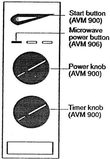
| AVM 900 mechan. model | 2/1 | - | -/- | - | -/x | -/- | - | 60 minutes | continuous + Jet level |
| 10:30 | AVM 902 electr. model | 1/8 | x(4) | -/- | - | 5/x | x/x | x | 90 minutes | 6+Jet level |
| AVM 906 mechan. model | 2/3 | - | x/x in all variable microwave power steps | - | -/x | -/- | - | 60 minutes | continuous + Jet level |
e eae
| +9 | sehme 06 | x | x/x | x/x | x | M 09L
'09E '09S
:Sees
Mew
- /x | 9 | 6/1 | pepepepepepepepepepepepepepepepepepepepepepepepepepepepepepepepepepepepepepepepepepepepepepepepepepepepepepepepepepepepepepepepepepepepepepepepepepepepepepepepepepepepepepepepepepepepepepepepepepepepe pepepepepepepepepepepepepepepepepepepepepepepepepepepepepepepepepepepepepepepepepepepepepepepepepepepepepepepepepepepepepepepepepepepepepepepepepepepepepepepepepepepepepepepepepepepepepepepepepepepepeopepepepepepepepepepepepepepepepepepepepepepepepepepepepepepepepepepepepepepepepepepepepepepepepepepepepepepepepepepepepepepepepepepepepepepepepepepepepepepepepepepepepepepepepepepepepepepepepepepepepeperperperperperperperperperperperperperperperperperperperperperperperperperperperperperperperperperperperperperperperperperperperperperperperperperperperperperperperperperperperperperperperperperperperperperperperperperperperperperperperperperperperperperperperperperperperperperperperperperperperper perperperperperperperperperperperperperperperperperperperperperperperperperperperperperperperperperperperperperperperperperperperperperperperperperperperperperperperperperperperperperperperperperperperperperperperperperperperperperperperperperperperperperperperperperperperperperperperperperperperper/perperperperperperperperperperperperperperperperperperperperperperperperperperperperperperperperperperperperperperperperperperperperperperperperperperperperperperperperperperperperperperperperperperperperperperperperperperperperperperperperperperperperperperperperperperperperperperperperperperperper-perperperperperperperperperperperperperperperperperperperperperperperperperperperperperperperperperperperperperperperperperperperperperperperperperperperperperperperperperperperperperperperperperperperperperperperperperperperperperperperperperperperperperperperperperperperperperperperperperperperperverperperperperperperperperperperperperperperperperperperperperperperperperperperperperperperperperperperperperperperperperperperperperperperperperperperperperperperperperperperperperperperperperperperperperperperperperperperperperperperperperperperperperperperperperperperperperperperperperperperper Per | |
| +9 | sehme 06 | x | x/x | x/x | - | M 09L
'09E '09S
:Sees
Mew
- /x | 9 | 8/1 | pepepepepepepepepepepepepepepepepepepepepepepepepepepepepepepepepepepepepepepepepepepepepepepepepepepepepepepepepepepepepepepepepepepepepepepepepepepepepepepepepepepepepepepepepepepepepepepepe pepepe pepe pepe pepe pepe pepe pepe pepe pepe pepe pepe pepe pepe pepe pepe pepe pepe pepe pepe pepe pepe pepe pepe pepe pepe pepe pepe pepe pepe pepe pepe pepe pepe pepe pepe pepe pepe pepe pepe pepe pepe pepe pepe pepe pepe pepe pepe pepe pepe pepe pepe perperperperperperperperperperperperperperperperperperperperperperperperperperperperperperperperperperperperperperperperperperperperperperperperperperperperperperperperperperperperperperperperperperperperperperperperperperperperperperperperperperperperperperperperperperperperperperperperperperper per | |
| +9 | sehme 06 | x | x/x | x/x | - | M 09L
'09E '09S
:Sees
Mew
- /x | 9 | 8/1 | pepepepepepepepepepepepepepepepepepepepepepe pepe pe pe pe pe pe pe pe pe pe pe pe pe pe pe pe pe pe pe pe pe pe pe pe pe pe pe pe pe pe pe pe pe pe pe pe pe pe pe pe pe pe pe pe pe pe pe pe pe pe pe pe pe pe pe pe pe pe pe pe pe pe pe pe pe pe pe pe pe pe pe pe pe pe pe pe pe pe pe pe pe pe pe pe pe pe pe pe pe pe pe pe pe pe pe pe pe pe pe pe pe perperperperperperperperperperperperperperperperperperperperperperperperperperperperperperperperperperperperperperperperperperperperperperperperperperperperperperperperperperperperperperperperperperperperperperperperperperperperperperperperperperperperperperperperperperperperperperperperperperper/per | |
E01 3d
| SSESS LLC | |
| SUNN DE LA VILLA | |
| WELL WILLIAMS | |
NEW FEATURES/ IMPROVEMENTS
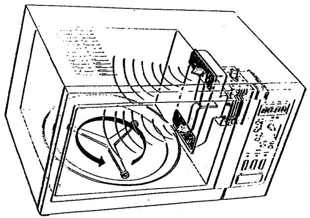
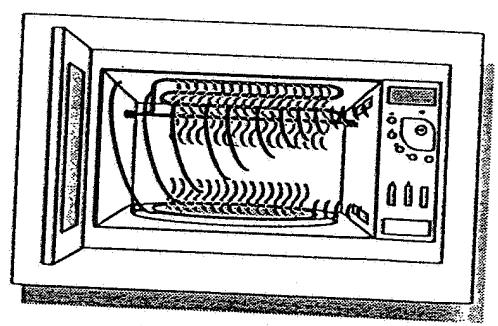
MICROWAVE FUNCTION TURNTABLE
The exclusive DOUBLE EMISSION SYSTEM (DES) feeds microwaves into the cavity from two entry points. The rotation on the turntable helps that energy will be uniformly picked up. The turntable consists of a roller cross and a turntable glass plate.
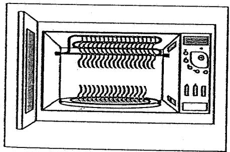
GRILL FUNCTION
The grill is a special high-density grill element. It is a "drop down" grill, which is very easy to clean.
CRISP
Combination: Grill function
Special metal dish
(200 °C in appr. than 2 minutes)
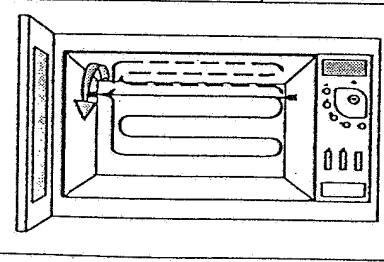
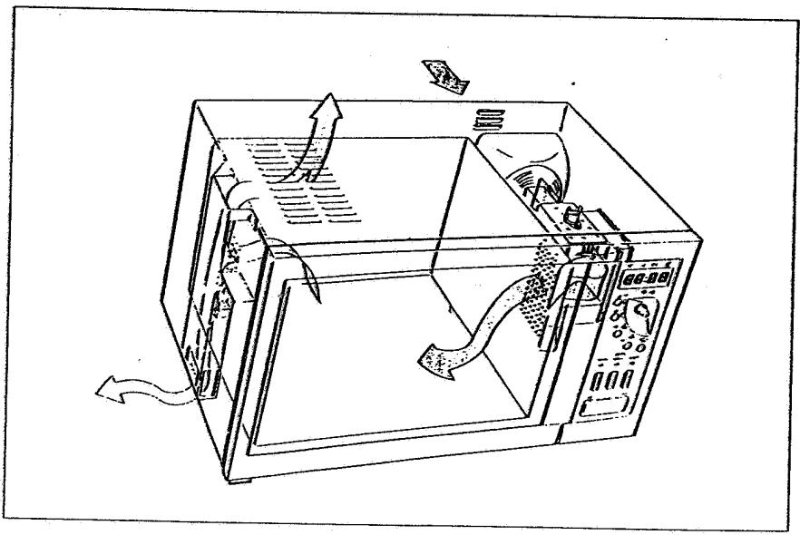
VENTILATION
AND AIR FLOW
| Interference filter
(1030) | DESCRIPTION AND FUNCTION OF COMPONENTS
Is intended to avoid interference with radio or TV sets during operation. |
| Fan motor
(1070) | The fan motor drives a blower fan which draws cooling air through the ventilation opening on the right side. Air is forced around the magnetron and transformer. This air is also forced into the cavity to make the antenna rotate and to remove steam and vapours from the cooking food. The air is then forced out through the ventilation openings on the left side. |
| Cavity lamp
(1125) | The cavity lamp illuminates the interior of the cavity so the food can be seen through the door window. The cavity lamp lights whenever cooking time is set. |
| High voltage transformer
(5000) | Purpose of HV transformer is to provide filament voltage for heating the magnetron filament as well as to produce high voltage used for magnetron tube operation. During a "cook" cycle, the 220 Vac(240 V) applied to the primary winding is converted into approximately 3.3V ac on filament winding, and into approximately 2300 Vac on the high voltage secondary winding of the power transformer. |
| Half wave voltage doubler circuit
(2000) | The half wave voltage doubler circuit consists of a rectifier and a capacitor with a bleeder resistor. The purpose of this group is to convert the 2300 Vac from the secondary winding of the high voltage transformer to approximately 4000 Vdc needed for magnetron operation. |
| Magnetron tube | The magnetron produces microwaves through the interaction of strong electric and magnetic fields. These microwaves are guided in-to the oven cavity by the rotating antenna. This produces the desired heat in the food. |
| Failure monitor switch
(1050) | This is normally an open switch, which is closed when the door is opened. Should then for any reason the door switch 1060 remain closed, the fuse will blow due to a short circuit. The short circuit current is limited by resistor 3104/3105. |
| Door switches
(1040, 1060) | These switches are safety switches operated by the door. The switch 1040 interrupts the current to the electric control and display panel. Switch 1040 is the primary door switch.
Note: Defective switches should be destroyed to prevent possible future use. |
| Grill element
(1180) | The grill element (in the VIP-27 range) can be folded down for easier cleaning of the cavity. |
| Turntable motor
(1080) | The turntable motor is a small synchronous motor that drives the turntable via a roller cross. The motor can start in either direction. |
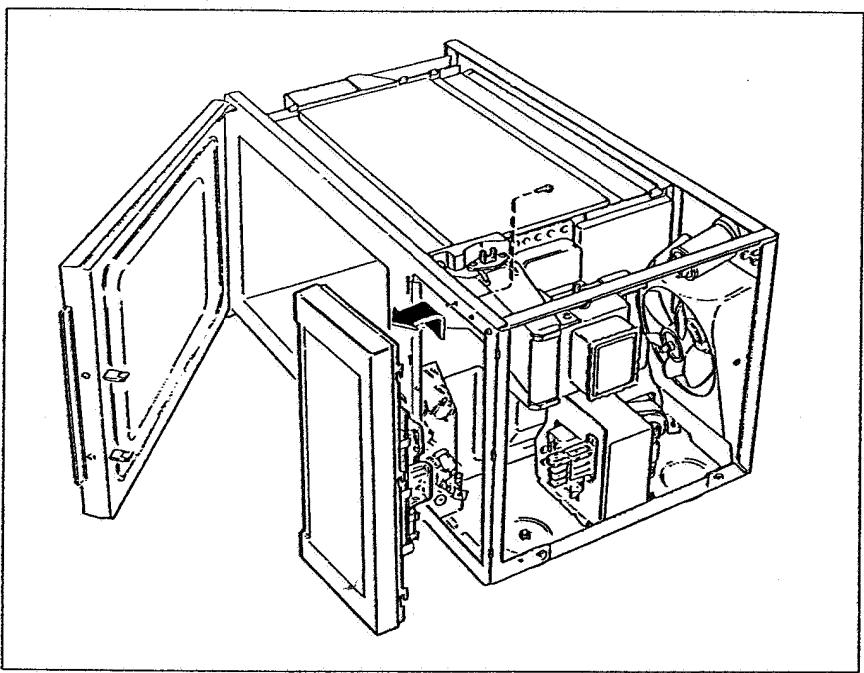
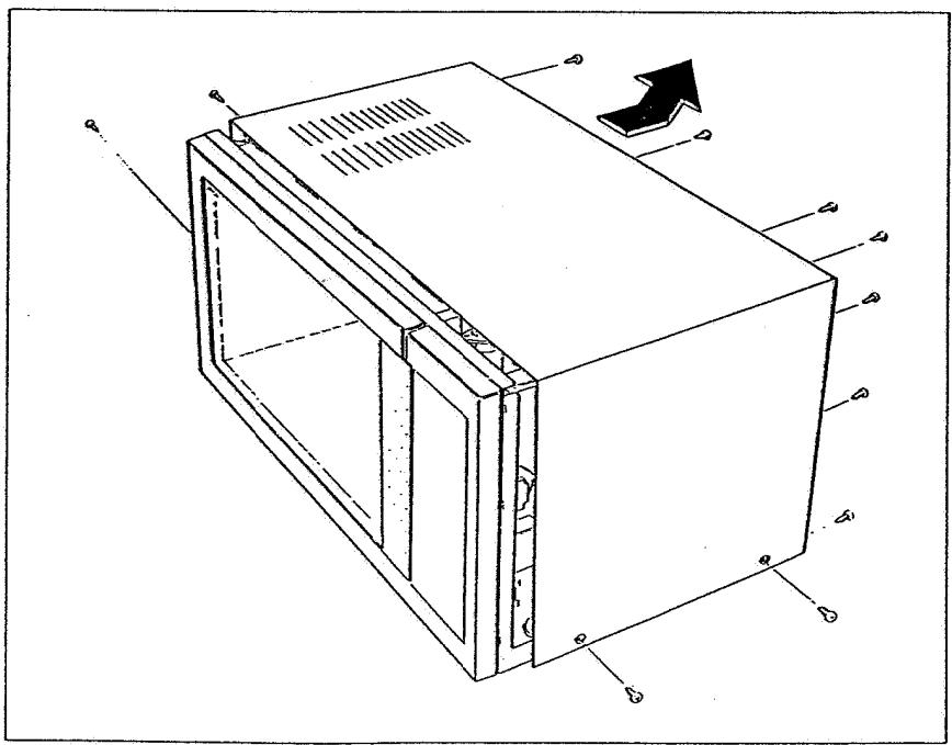
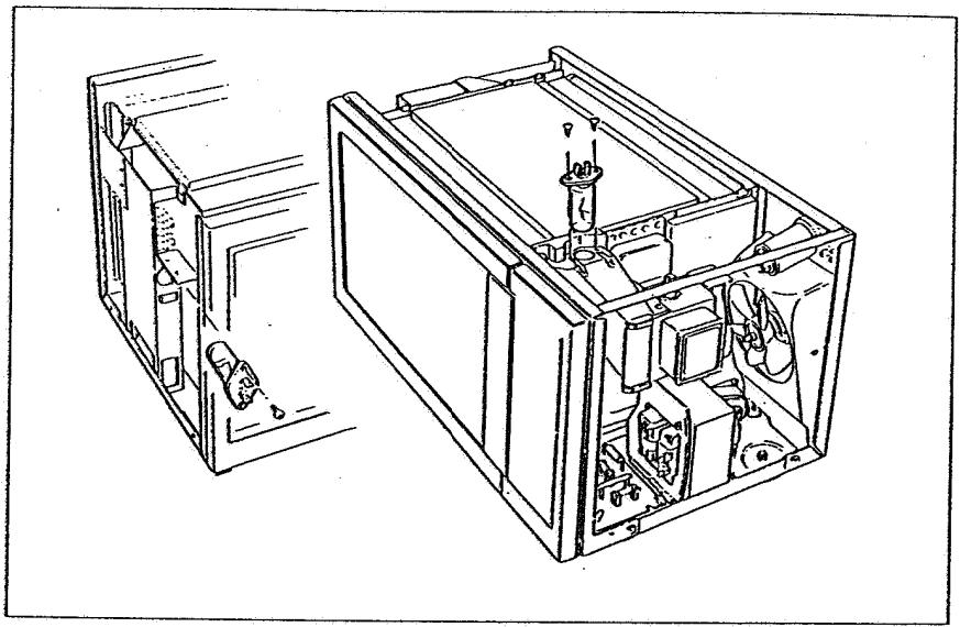
ASSEMBLY AND DISASSEMBLY
WARNING
Before removing the outer case unplug the oven. High voltage parts are accessible when the outer case is removed.
FRONT PANEL REMOVAL
TOP PLATE REMOVAL
CHANGING CAVITY LAMP
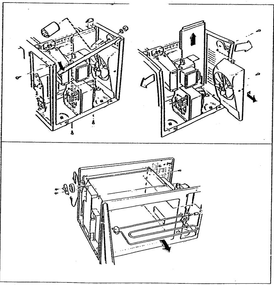
CHANGING
GRILL ELEMENT
Attention: Before changing the grill element remove fan unit.
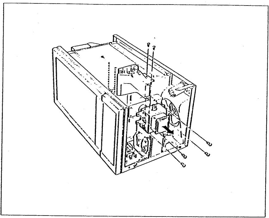
CHANGING MAGNETRON
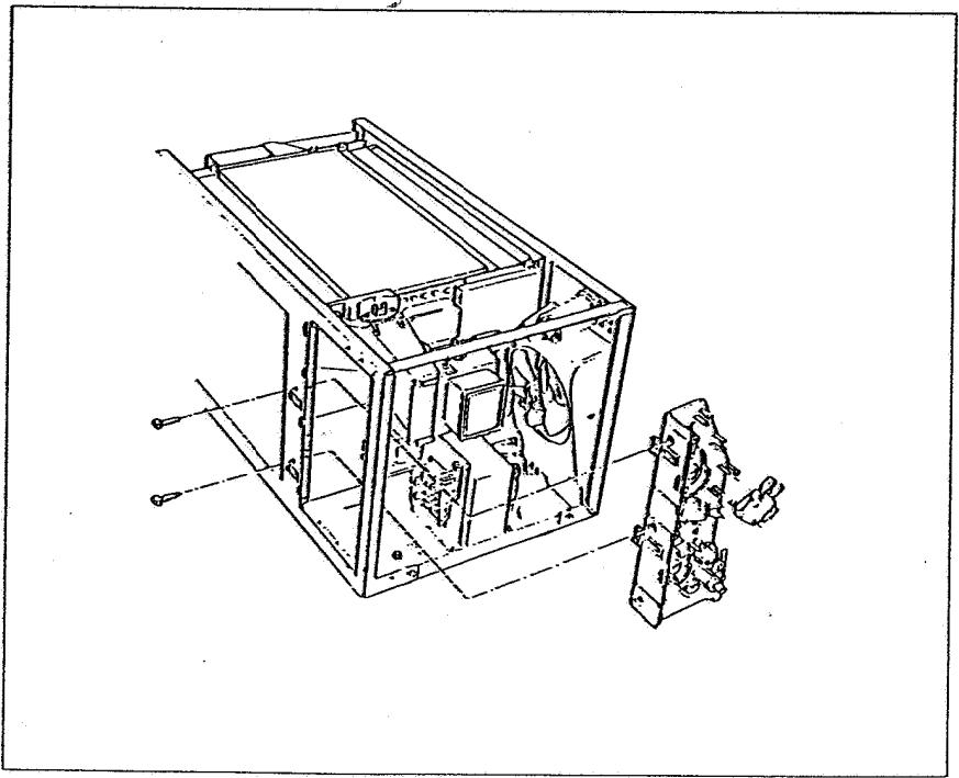
CHANGING DOOR SWITCH UNIT
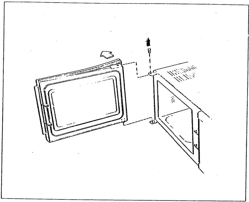
DOOR REPLACEMENT
MEASUREMENTS AND ADJUSTMENTS
Filament voltage check
Caution: Approximately 2300 Vac are present at the high voltage terminals of the transformer during a cook cycle. During test operation keep meter, hands,etc., well away from high voltage terminals.
- Disconnect the oven and discharge the capacitor with an insulated screwdriver.
- Remove wires connecting the capacitor to the high voltage terminal on the transformer.
- With alligator clips, connect the voltmeter across the magnetron filament terminals and stand well away from the meter and it's leads.
- Apply power and put the oven into cook cycle. The meter should indicate approximately 3.3 Vac.
Caution: Switch off the oven before disconnecting the meter.
- If no voltage is indicated by the meter, set the meter on the proper range and check if 220V (240 V) ac are present at the primary winding of the transformer during the "cook" cycle. If the input voltage is normal but no filament voltage is present, replace HV transformer.
Anode voltage
Due to the presence of the high voltage (approx. 4 KV) it is for safety reasons not allowed or necessary to measure anode voltage. Normally a continuity test of transformer windings and a capacitor check as described in components checks are sufficient to determine if anode voltage is correct.
Measuring the output power
The temperature of one liter of water will rise 14.3 degrees Celsius per minute if the output power of the oven is 1kW :
For measuring the output power, proceed as follows:
Check that the oven and the bottom tray are clean.
Place one thin walled glass beaker with a diameter of approx. 10~cm filled with 1 liter of water, in the center of the oven cavity after measuring the water temperature.
Start the oven at max. for 1 minute, checked by the watch. (start measuring time when hum
Measure the average temperature increase, i.e. temperature after 1 minute minus temperature at beginning.
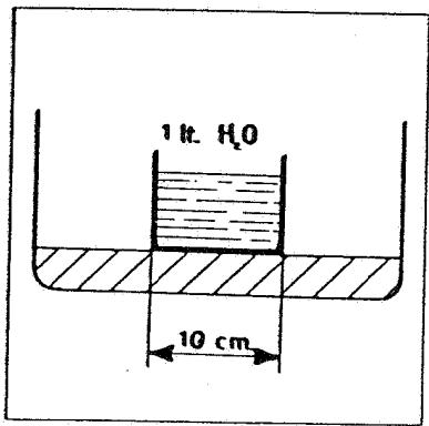
Divide the results by 14.3.The value equals the power in kW.
The output power of the oven should be higher than 850 W minus 20% for the lifetime of the oven.
Repeat this measurement a few times.
Note: This test is only meant as an indication, and will not be accurate to give an exact output power.
R. F. LEAKAGE
Important
An R.F. leakage check should be performed before and after every repair or adjustment.
To perform the R.F. leakage check proceed as follows:
- Fill a glass beaker with 275ml of tap water and place it in the centre of the cavity.
- Adjust the R.F. meter according to operational instructions.
- Start the oven on full power. Set the timer to at least 3 minutes.
- Check the oven by moving the probe not faster than 5 centimeters per second, starting at the right hand top side of the door, clockwise, back to the starting position. A check must also be made over the entire visual screen. Readings always have to be below 5 mW/cm².
Note: For a proper leakage test, position the oven so that it is possible to run the probe under and perpendicular to the bottom edge of the door.
Important
If the reading is over 5mW/cm^2 , the oven door should be checked for damages, and the door alignment to the cavity should be checked. Make sure that the door closes properly.
COMPONENTS CHECK
Magnetron check Filament check
Disconnect the oven. Discharge the HV capacitor. Disconnect the hight voltage wires from the magnetron filament terminals. Correct reading is less than 1 Ohm. If high resistance or infinite resistance is found, replace the magnetron.
Shorted magnetron test
Connect ohm-meter between magnetron filament terminals and chassis. The reading should be infinite. If there is low resistance, the magnetron is grounded and must be replaced.
Note: When replacing the magnetron:
Do not reverse wires connected to magnetron terminals.
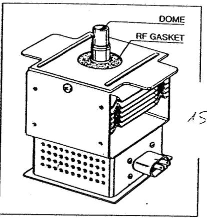
- Do not operate the oven with the R.F. gasket missing or damaged. The R.F. gasket is located around the dome of the magnetron to prevent any leakage of energy from it.
Caution: When replacing the magnetron, care has to be taken that the dome is not scratched by any metal parts. Small particles of any metal in the ceramic dome will greatly reduce the life of the magnetron.
Capacitor check
An open circuit capacitor will result in no high voltage to the magnetron.
A shorted capacitor normally causes high current blowing the fuse line.
An ohmmeter can be used to check for a shorted or open capacitor.
- Unplug the oven. Discharge the capacitor. Remove wires from capacitor.
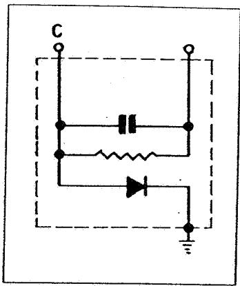
- With an ohmmeter set on the highest scale, measure the resistance across terminals "C" and the other terminal. The meter needle should momentarily deflect upward to indicate continuity and should then return to infinity once the capacitor is charged. Reversing the meter leads should give the same indication.
- If the ohmmeter indicates continuity between the capacitor terminals at all times. If no meter deflection occurs at all, the capacitor should be replaced. Connect ohm-meter between magnetron filament terminals and chassis. The reading should be infinite. If there is low resistance, the magnetron is grounded and must be replaced.
Diode check
The high voltage diode is built-in in the same case as the HV capacitor.
Unplug the oven, discharge the capacitor, and remove wires from it. With an ohmmeter set on the highest scale, measure the resistance across terminal "C" and capacitor case. Reverse the meter leads and again observe the resistance reading. A normal diode should read infinite resistance in one direction, and approximately 50 ohms or less when the meter leads are reversed.
Note: Meters operated with less than 6 V battery are not adequate for these checks. The meter should first be checked with a diode known to be good before judging a diode to be defective.
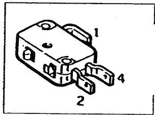
Safety switches check
Disconnect the oven, remove wire 1 of the switch, connect an ohmeter to the terminals 1 and 4. With closed door reading should be short circuit. With open door reading must be infinite. If reading is short circuit, or infinite all the time, the switch must be replaced.
Note: If a safety switch is replaced, make sure it is activated when the door is closed.
Failure monitor switch check
Disconnect the oven, remove one wire from the switch, connect an ohmmeter to the terminals of the switch. With open door reading has to be short circuit. With closed door reading has to be infinite. If reading is short circuit or infinite all the time, the switch must be replaced.
Note: When replacing the failure monitor switch, make sure the switch is activated when the door is open.