
2130 - Récepteur audio-vidéo MARANTZ - Notice d'utilisation et mode d'emploi gratuit
Retrouvez gratuitement la notice de l'appareil 2130 MARANTZ au format PDF.


| Type de produit | Récepteur audio-vidéo |
| Marque | Marantz |
| Modèle | 2130 |
| Dimensions (L x H x P) | 416 x 146 x 301 mm |
| Poids (seul) | 9 kg |
| Poids (emballé) | 11 kg |
| Alimentation | 120 V AC, 60 Hz, 30 W |
| Fusible de protection | 1 A, 250 V |
| Gammes de fréquences | FM et AM |
| Sensibilité FM (IHF) | 1,5 µV (8,75 dBf) |
| Sélectivité FM (large/étroit) | 45 dB / 85 dB |
| Séparation stéréo (1 kHz) | 55 dB (large), 50 dB (étroit) |
| Distorsion FM mono (1 kHz) | 0,05% (large), 0,07% (étroit) |
| Rapport signal/bruit FM mono | 83 dB |
| Affichage | Oscilloscope intégré (tubes cathodiques) |
| Système de verrouillage | Quartz Lock (verrouillage par quartz) |
| Filtre antiparasite MPX | Oui |
| Largeur de bande FI | Sélectionnable : Large ou Étroit |
| Sorties audio | 2 x RCA (gauche/droite), niveau réglable |
| Sortie secteur non commutée | 1 prise (arrière) |
| Entrée antenne FM | 300 Ω (symétrique) et 75 Ω (coaxiale) |
| Antenne AM | Ferrite rotative (intégrée) + borne extérieure |
| Options adaptables | Décodeur Dolby FM DLB-1, adaptateur rack RHA-1, coffret noyer WC-136 |
| Entretien | Nettoyer avec un chiffon doux non pelucheux légèrement humidifié (eau savonneuse douce). Ne pas utiliser de produits abrasifs. |
| Sécurité | Ne pas exposer à la pluie ni à l'humidité. Débrancher avant de remplacer le fusible. |
| Réparabilité | Fusible remplaçable par l'utilisateur. Pour autres réparations, contacter un service agréé Marantz. |
| Garantie | 2 ans pièces et main-d'œuvre (tuner), 90 jours pour tube oscilloscope |
FOIRE AUX QUESTIONS - 2130 MARANTZ
Questions des utilisateurs sur 2130 MARANTZ
0 question sur cet appareil. Repondez a celles que vous connaissez ou posez la votre.
Poser une nouvelle question sur cet appareil
Téléchargez la notice de votre Récepteur audio-vidéo au format PDF gratuitement ! Retrouvez votre notice 2130 - MARANTZ et reprennez votre appareil électronique en main. Sur cette page sont publiés tous les documents nécessaires à l'utilisation de votre appareil 2130 de la marque MARANTZ.
MODE D'EMPLOI 2130 MARANTZ

Handbook of Instructions

Model 2130 AM/FM Stereophonic Tuner
FOREWORD
Congratulations! Judging by the stereo equipment you now own, you are no amateur when it comes to audio. Nevertheless, we urge you to study these instructions carefully. Our step-by-step procedures will assure you of receiving maximum enjoyment from the superb performance the Model 2130 is capable of giving.
AFTER UNPACKING
The original packing material is specifically designed to protect the unit, and replacement packing material from Marantz is expensive. Therefore, it is advisable to retain all original packing material to prevent damage should you wish to transport or ship the Model 2130 in the future (refer to page 18 for repacking and shipping instructions). Be careful that you do not inadvertently throw away or lose the parts packed with the unit.
Please inspect your Stereophonic Tuner carefully for any signs of shipping damage. Our very strict quality control and professional pride ensure that each left the factory in perfect condition. If the unit is damaged or fails to operate, immediately notify your dealer. If the unit was shipped to you directly, notify the transportation company without delay. Only you, the consignee, may institute a claim against the carrier for shipping damage. Save the carton and all packing material as evidence of damage for their inspection. Should assistance be required, the Marantz Company will cooperate fully in assisting your claim. We strongly advise that you retain your sales receipt to provide proof of purchase in the event that Warranty service is sought.
ABOUT THIS MANUAL
For convenience, this manual is divided into three parts. The first part covers installation. The second part covers operation. These two parts are written in simple, non-technical terms. The third part provides a more detailed description of the technical features of the Model 2130, and will be interesting to read after your system is set up and playing.
To provide a means for readily distinguishing between references to the controls and connection facilities of the Model 2130 and those of the other system components, BOLDFACE type is used for references to the Model 2130. Notice that the spelling and abbreviations of all such markings appear exactly as lettered on the front and rear panels of the instrument.
PURCHASER'S RECORD
MODEL NO. (Located on Front of Unit)
SERIAL NO. (Located on Rear of Unit)
Cost Date
This information becomes your permanent record of a valuable purchase. It should be filled in promptly then kept in a safe place along with your purchase receipt to be referred to as necessary for insurance purposes or when corresponding with Marantz.
IMPORTANT
WHEN SEEKING WARRANTY SERVICE, IT IS THE RESPONSIBILITY OF THE CONSUMER TO ESTABLISH PROOF AND DATE OF PURCHASE. (YOUR PURCHASE RECEIPT OR INVOICE IS ADEQUATE FOR SUCH PROOF.)
WARNING: TO PREVENT FIRE OR SHOCK HAZARD, DO NOT EXPOSE THIS APPLIANCE TO RAIN OR MOISTURE.
TABLE OF CONTENTS
PREPARATION FOR USE 3
Mechanical Installation 3
Marantz Walnut Veneer Cabinet 3
Rack Adapter 3
Custom Installation 3
Signal Connections 4
Output Jacks 4
AM Antenna 5
FM Antenna 5
Outdoor FM Antennas 5
Outdoor AM Antenna 7
Operating Power Connection 7
Convenience Outlet 7
AC Protector Fuse 7
Dolby Plug-in FM Decoder Installation 7
Signal Connection Checklist 7
OPERATION 8
Simplified Operating Procedures 8
Simplified Scope Procedures 8
Front Panel Features 8
Power Switch 8
Mono Switch 8
MPX Noise Filter Switch 9
Output Level Control 9
Muting Level Control 9
IF Bandwidth Switch 9
Quartz Lock Switch 9
Record Level Tone Switch 9
FM 25 S Switch 9
Recording Dolbyized FM Programs 10
Oscilloscope 10
Focus and Brightness Adjustments 11
FM Tuning Display 11
AM Tuning Display 11
FM Multipath Indication 11
Audio Display Switch 12
External Audio Scope Display 13
TECHNICAL SECTION 15
Technical Highlights 15
Dual Gate MOSFET Front End 15
Quieting Slope 15
Linear Phase IF Section 15
Parametric Muting Circuit 16
Quartz Locked System 16
Stereo Demodulator 16
MAINTENANCE 18
Cleaning 18
Fuse Replacement 18
In Case of Difficulty 18
Repairs 18
Repacking for Shipment 18
LIST OF ILLUSTRATIONS
1.Custom Mounting 3
2. Rear Panel 4
3. Connection Diagram 4
4.AM Ferrite-rod Antenna 5
5. FM Antenna Connection 5
6. Outdoor FM Antenna 6
7. Front Panel 8
8.FMTuningDisplay 11
9.AMTuningDisplay 11
- FM Modulation Characteristics 12
- Multipath Distortion Characteristics 12
- Audio Display 13
- Functional Block Diagram 14
- Dual Gate MOSFET 15
- Quieting Slope 16
16.Pilot Cancelling Circuit 17 - Repacking Illustration 19
PREPARATION FOR USE
In this section of the manual, you will find information about methods of attractively installing your new Marantz tuner, and about how to hook up the various wires and cables on the rear panel. We will also offer advice on how to choose an antenna system that will give your new tuner the best possible reception.
MECHANICAL INSTALLATION
The Model 2130 Stereophonic Tuner can be installed in three basic ways: In a beautiful walnut veneer cabinet for placement on a table or shelf, in a standard equipment rack for professional usage, or in your own cabinetry or custom installation.
MARANTZ WALNUT VENEER CABINET
An optional walnut veneer cabinet, Model WC-136, may be obtained from your Marantz dealer. The case provides for proper ventilation, and can be placed on furniture, or on a bookshelf. Complete instructions for installation are provided with the WC-136.
RACK ADAPTOR
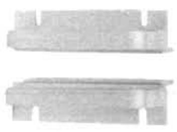
The optional Marantz RHA-1 Rack Adaptor attaches to the front panel of the Model 2130 enabling the unit to be mounted in a standard 19-inch equipment rack. The RHA-1 is gold anodized for maximum durability and professional appearance. It is supplied with side support brackets, all necessary hardware, and complete installation instructions.
CUSTOM INSTALLATION
If you wish to install the Model 2130 in a custom cabinet, plan its location carefully. Pay close attention to the following requirements:
-
The tuner is air cooled. Allow plenty of space between the Model 2130, cabinet surfaces, and other components for adequate ventilation.
-
Allow enough room behind the unit to extend the AM ferrite-rod antenna and to run cables.
-
Because of its weight, the Model 2130 cannot be supported by its front panel alone. The chassis should be supported by an internal shelf, a bracket, or similar means. If a solid shelf is used, provide one inch wood spacers at each corner of the chassis to allow the unit to have proper clearance from the shelf.
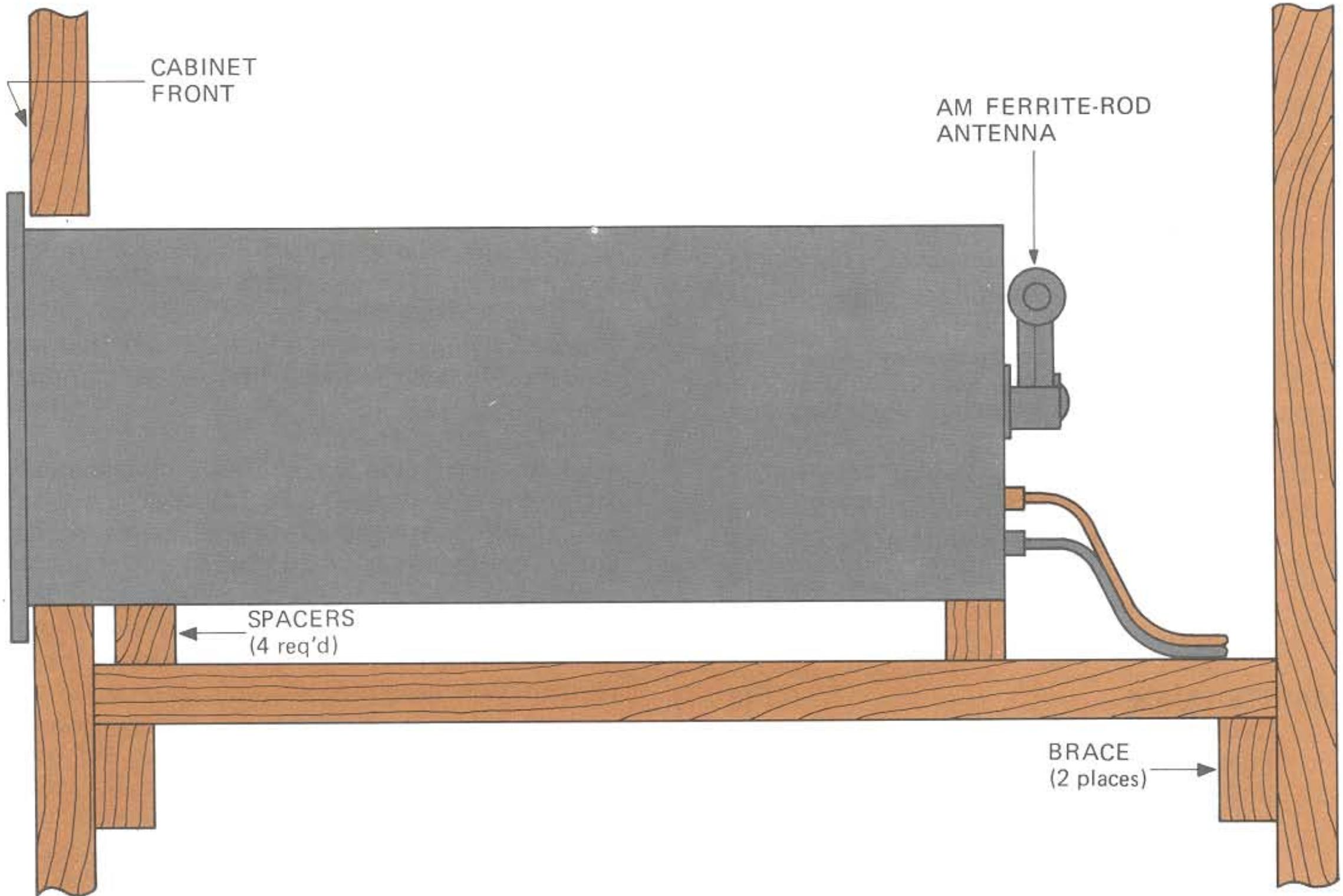
Figure 1.Custom Mounting
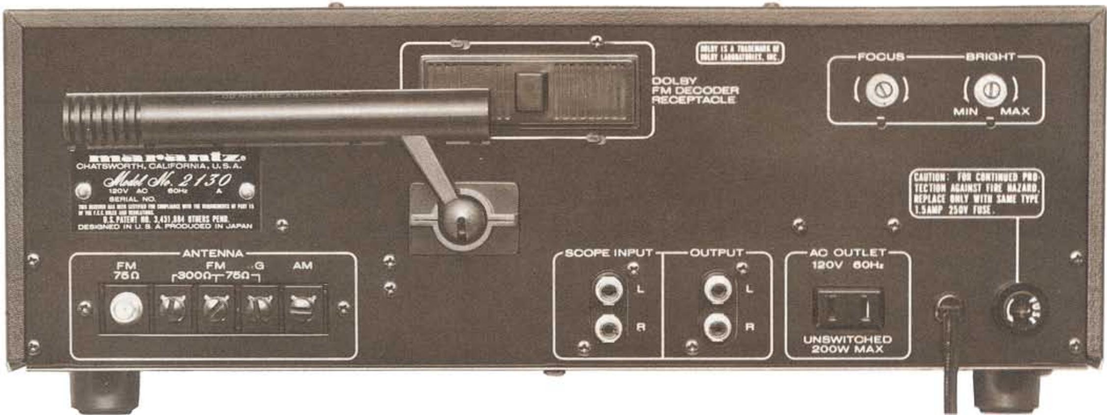
Figure 2. Rear Panel
Figure 1 is a side view of the Model 2130 in a custom enclosure, showing the internal shelf and bracing.
The opening in the cabinet front will be 16^ wide by 5-3/8" high. Since the front panel of the Model 2130 is larger than the cutout, it will neatly hide the edges of the cut. Remove the plastic feet from the bottom of the unit, and slide it through the opening.
SIGNAL CONNECTIONS
Figure 2 shows the location of the input and output jacks on the rear panel. These jacks are for "permanent" connections. Front panel switches and their use will be discussed later.
OUTPUT JACKS
The signal output selected by the AM or FM pushswitch on the front panel is fed to the left and right OUTPUT jacks. Using the stereo shielded audio cable supplied with the Model 2130, connect the tuner OUTPUT to the "TUNER" input jacks on your preamplifier or integrated amplifier, as shown in Figure 3. If no "TUNER"
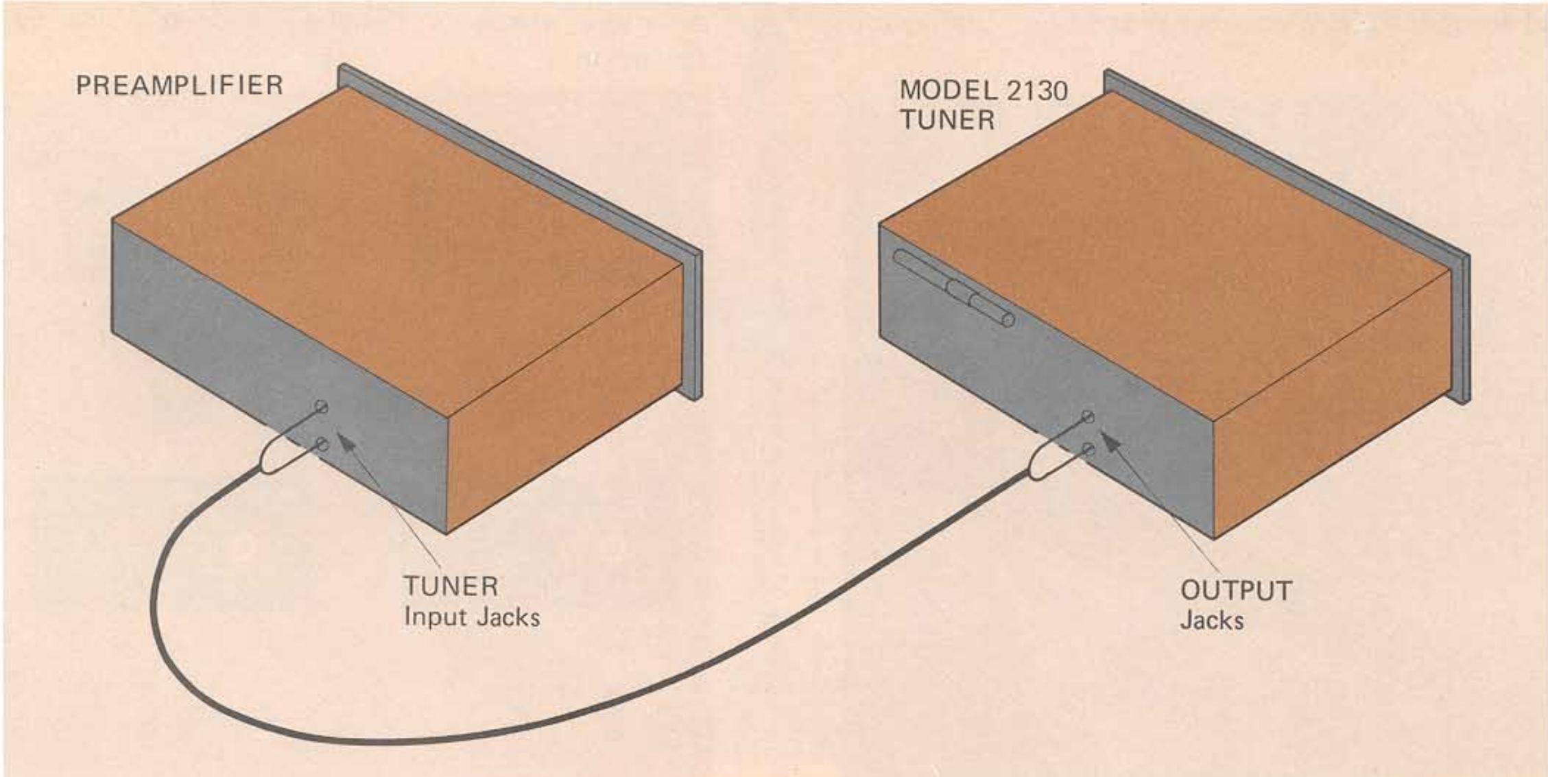
Figure 3. Connection Diagram
inputs are available, connect them to the "AUX" inputs. If your installation requires a longer cable than the one supplied, longer cables are available at your dealer. Distances of up to about 25 feet may be used.
The left and right signal output level can be varied by rotating the OUTPUT LEVEL control on the front panel. Both of the output levels have been adjusted to give about one volt signal output for 100% frequency modulated signals when the OUTPUT LEVEL control is placed in the fully clockwise position.
AM ANTENNA
Your Tuner is equipped with an AM ferrite-rod antenna. BEFORE USING THE MODEL 2130 SWING THE ANTENNA OUT AS SHOWN IN FIGURE 4.
The ferrite-rod antenna can be swiveled and will give you satisfactory results in primary signal areas. However, an outdoor antenna will provide better reception in weaker signal areas. See "OUTDOOR AM ANTENNA" section, page 7.
FM ANTENNA
Included in the accessory kit is a ribbon-type "folded dipole" FM antenna. This type of antenna is simple and practical and will give adequate results in primary signal areas. To use it, unfold it into a "T" shape and connect its leads to the terminals marked "300Ω" on the back of the tuner (See Figure 5A). The antenna is designed to operate in a horizontal position. Temporari
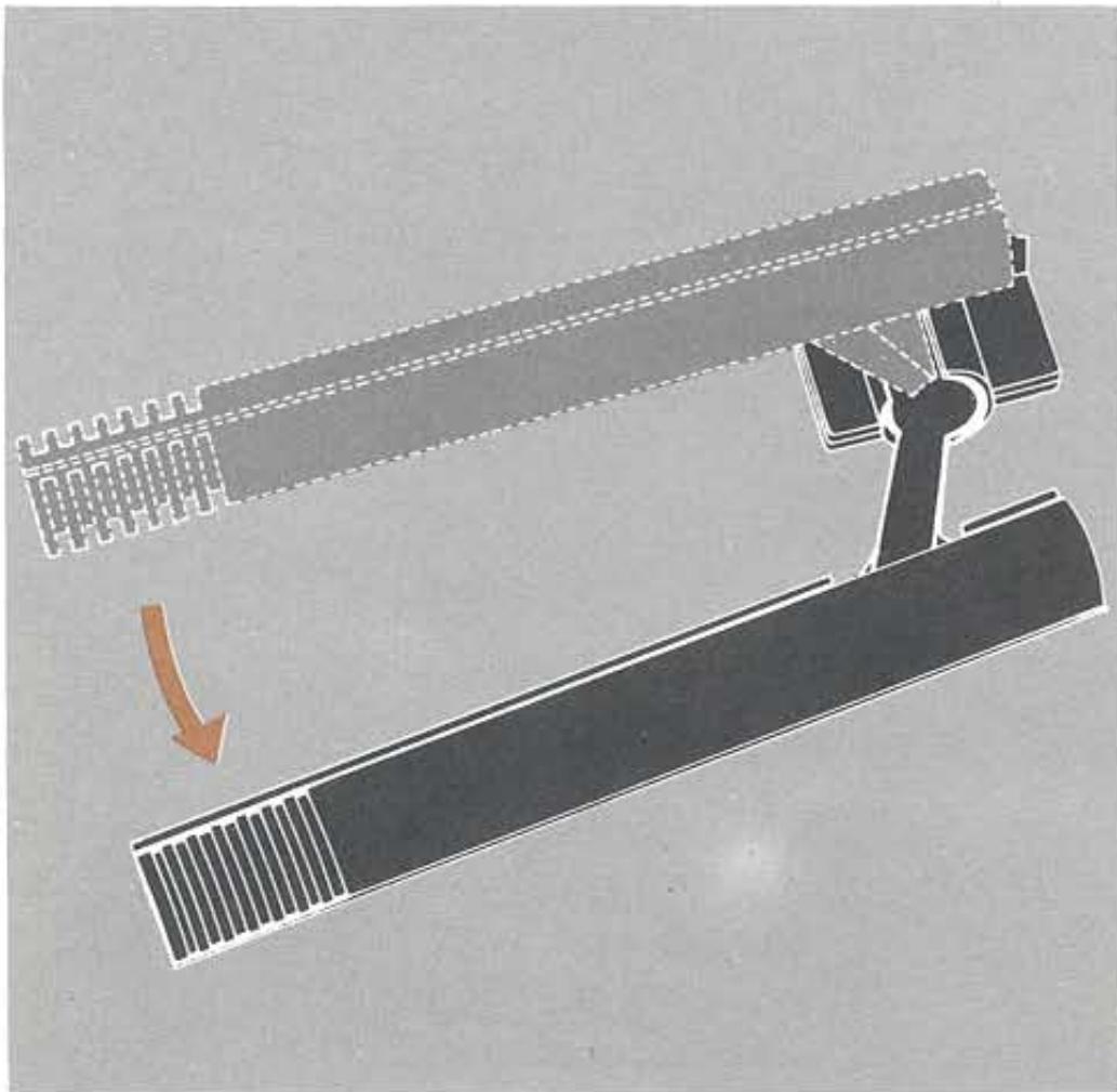
Figure 4. AM Ferrite-rod Antenna
ly (for the purpose of getting started) attach it to a nearby wall.
As shown in Figure 5, Model 2130 is also capable of accommodating other types of cable, including 75-ohm coaxial cable (with or without "F"-type connector), and 300-ohm shielded transmission line. These types of cable are for use with outdoor antennas, which will be discussed next.
OUTDOOR FM ANTENNAS
As stated before, the supplied folded dipole antenna will give satisfactory results in primary signal areas. It should be obvious, however, that if you are located in a fringe area where signals are weak, then an outdoor directional antenna may be needed to eliminate "multipath" reflections.
Multipath reflections are responsible for much of the distortion and sibilance associated with poor FM reception. They occur when radio waves from the transmitter bounce off of nearby mountains and tall buildings. The reflected waves follow different, more roundabout paths to your tuner and arrive slightly delayed and out of phase with the direct signal (hence, the term "multipath"). This causes distortion in the same manner that "ghost" images are generated on television.
The way to minimize multipath is to use a "beam type" antenna that can be aimed toward the FM transmitter and away from the multipath reflections. The best types of antenna to use are either a "Yagi" or "Log-Periodic" configuration with six or more elements designed expressly for FM reception.
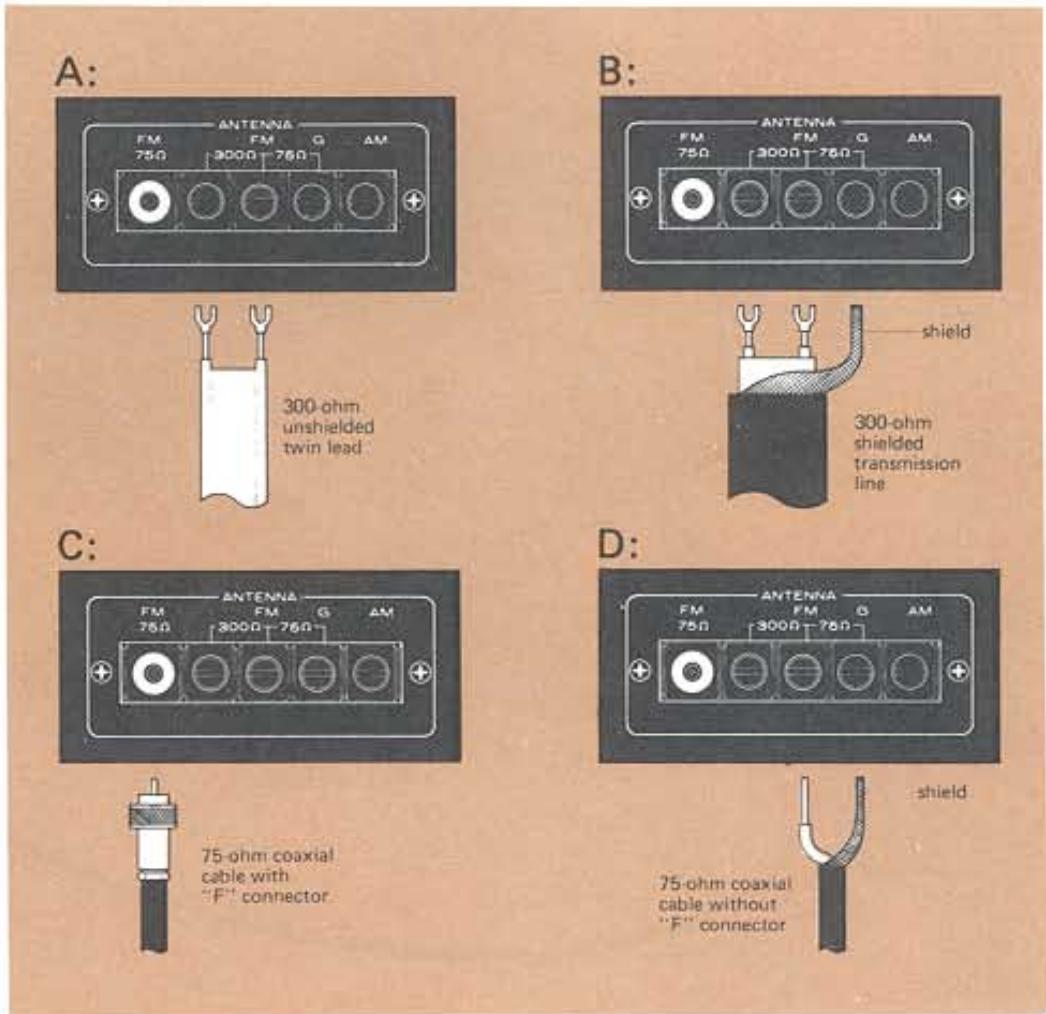
Figure 5. FM Antenna Connection
If you want to receive stations from more than one general direction, then you will need a good quality antenna rotor system. This will enable you to point the antenna in the direction giving the least multipath interference, by means of a control box located near the tuner.
Another important factor is the type of lead-in wire to use. Unshielded lead-in wires, such as 300-ohm twin lead, can act as an omnidirectional antenna, and can cancel the directional benefits of your antenna. Therefore, we recommend using a balanced, shielded 300-ohm cable or a coaxial 75-ohm cable with a 300-to-75-ohm matching transformer at the antenna. These types of shielded cable effectively prevent the lead-in from contributing to multipath distortion.
Shielded antenna cable will be available at the same store where you buy your antenna. If you decide to use 75-ohm coaxial cable, we recommend buying cable with "F"-type connectors attached. These will fit both the matching transformer and the terminal on the Model 2130 (See Figure 5C).
It is considered good practice to connect the antenna mast to an earth ground, both for reasons of safety and noise reduction. If shielded 300-ohm antenna cable is used, though, connect the shield to ground (G) at the Tuner end only.
For rural areas, it is recommended to consult a local dealer about installation and lighting arrester protection.
We don't recommend using master antenna systems, such as those found in apartment buildings. Such systems are usually designed expressly for television reception and frequently suppress or reduce the quality of the FM signals before distribution.
Where outdoor antennas are prohibited or inconvenient, the simplest form of "rabbit-ear" TV antenna is the most practical and will give satisfactory results. This type is preferred over the folded dipole because it can be more readily rotated for the best reception.
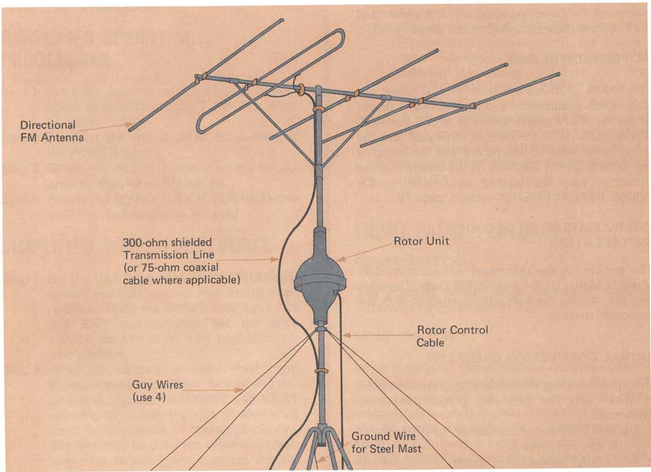
Figure 6. Outdoor FM Antenna
OUTDOOR AM ANTENNA
Two single wires are required to make an AM outdoor antenna. First, connect one end of a single wire to the AM ANTENNA terminal on the rear panel, and the other end to a very high horizontal antenna wire of 25 to 75 feet in length suspended between insulators in an outdoor location (the higher the better). Next, connect the second single wire between the G terminal of your Model 2130 and an authenticated earth ground (such as a metal water pipe).
OPERATING POWER CONNECTION
With the front panel POWER pushswitch "OUT", plug the line cord into an electrical outlet supplying the proper voltage (120 V).
CAUTION:
DO NOT PLUG YOUR MODEL 2130 INTO A DC OUTLET AS SERIOUS DAMAGE WILL OCCUR.
CONVENIENCE OUTLET
One UNSWITCHED AC outlet is provided on the rear panel for powering associated components of your system (tape recorder, record player, etc.)
AC PROTECTOR FUSE
The Model 2130 has a fuse in the AC power circuit which automatically disconnects AC power in the event of a power source or circuit overload. If the POWER pushswitch is activated and the front panel fails to illuminate and no sound is heard through the speakers, it is possible that the protector fuse has burned out. Refer to the "FUSE REPLACEMENT" section, page 18.
DOLBY PLUG-IN FM DECODER INSTALLATION
The pocket on the rear panel will accommodate Marantz Model DLB-1 Plug-in FM Dolby Decoder. For use, follow the instructions supplied with the optional decoder.
SIGNAL CONNECTION CHECKLIST
Before proceeding with operation, double check to make sure the following preparations have been made.
- OUTPUT of tuner connected to TUNER or AUX input of preamp.
- ANTENNA connected properly.
- AM FERRITE-ROD antenna extended.
- AC LINE CORD plugged in.
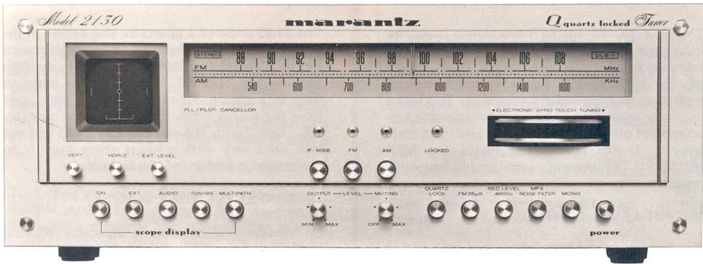
Figure 7. Front Panel
OPERATION
This section of the manual will tell you how to operate your new tuner. First, a simplified operating procedure will be outlined to get you started. Then, the front panel features will be discussed individually in more detail.
SIMPLIFIED OPERATING PROCEDURES
Step 1. Place the selector switch of your preamplifier or amplifier to the TUNER or AUX position.
Step 2. Turn on the Model 2130 by depressing the POWER switch.
Step 3. Select the desired program source by depressing the AM or FM switch.
Step 4. Rotate the GYRO-TOUCH TUNING knob until the desired station is tuned.
SIMPLIFIED SCOPE PROCEDURES
Step 1. Set the VERT (vertical) and HORIZ (horizontal) controls to their mid (straight up) position. Press the SCOPE DISPLAY ON and EXT pushswitches. Set the EXT LEVEL control to its fully counterclockwise position.
Step 2. After 30 seconds, a small "dot" will appear somewhere on the face of the display area. Adjust the HORIZ and VERT controls to center the dot in the small circle in the center of the scope display. The dot may be dim, but automatic beam intensifier circuitry will brighten the display when a signal is applied to the scope circuitry.
Step 3. Depress the TUNING pushswitch. For FM broadcasts, rotate the tuning knob until the dot is located near the center of the screen. For AM broadcasts, rotate the tuning knob until the maximum height is obtained. For detailed information, refer to the "OSCILLOSCOPE" section starting on page 10.
Step 4. Depress the MULTIPATH pushswitch. Rotate your antenna until the flattest, most horizontal line is obtained. For detailed information, refer to the "FM MULTIPATH INDICATION" section on page 11.
Step 5. A visual representation of the left and right channel signals may be obtained by pressing the AUDIO pushswitch. An analysis of the different figures is given on page 13.
FRONT PANEL FEATURES
POWER SWITCH
The POWER switch, when depressed, supplies AC power to the Model 2130.
MONO SWITCH
When a marginal stereo signal is received, random noise and phase modulation may cause the tuner's multiplex circuitry to trigger the stereo mode intermittently. In this case, it is sometimes desirable to cancel the multiplex operation entirely in favor of obtaining a more listenable signal. The MONO switch performs this function and converts all output signals to the MONOPHONIC mode.
MPX NOISE FILTER SWITCH
The MPX NOISE FILTER function is useful for reducing noise on weak stereo FM signals with excessive noise and/or interference. When activated, the MPX NOISE FILTER slightly reduces separation at high audio frequencies. This offers moderate separation along with considerable suppression of out-of-phase noise and distortion components. Unlike most noise filters, the MPX NOISE FILTER does not sacrifice full frequency response.
OUTPUT LEVEL CONTROL
This control attenuates the level of both stereo output channels to match the line level of other components in the system.
NOTE: The OUTPUT LEVEL does not operate when the FM 25 s switch is depressed. Instead output level is internally set to the standard level for Dolby-ized broadcasts.
MUTING LEVEL CONTROL
In the absence of an FM carrier, all FM receivers produce noise. This noise is apparent between stations while tuning.
This control activates the mating circuit to eliminate interstation noise. The mating threshold can be varied by rotation of the MUTING LEVEL control. To prevent mating very weak stations along with the noise, the mating function may be defeated by placing this switch in the OFF position.
IF BANDWIDTH SWITCH
This switch controls the bandwidth of the IF amplifier inside the tuner. The two positions of the switch allow you to optimize the performance of the tuner in one of two ways:
-
The WIDE band position (in) improves the tune's linearity. The results are superior channel separation and greatly improved total harmonic distortion.
-
The NARROW band position (out) offers the ultimate in alternate channel selectivity in exchange for only a slight performance trade-off in stereo separation and total harmonic distortion. This position provides greater immunity to interference where stations are closely spaced on the FM band.
QUARTZ LOCK SWITCH
The 2130 employs a quartz locking system in the FM tuning circuitry that will assure exact station tuning. Depress the QUARTZ LOCK pushswitch and use the TUNING function of the scope to tune in a station. When you remove your hand from the tuning knob, the Quartz Lock circuitry will "lock" onto the station. The 2130 will not lock onto very weak stations where there is an overpowering amount of hiss and noise.
RECORD LEVEL TONE SWITCH
On certain FM broadcasts, especially classical music programs, the volume level of the music is sometimes quite unpredictable. Sometimes they begin softly and unexpectedly become very loud.
When recording such an FM broadcast onto a tape recorder, it is often difficult at the beginning to guess the proper setting of the recorder's input level controls for optimum recording.
The RECORD LEVEL 400 Hz generator in the Model 2130 eliminates this guesswork by supplying a stable sine wave tone at the tuner outputs. This tone may be used as a reference for setting the levels on the tape recorder before the actual program begins.
In effect, the RECORD LEVEL 400 Hz enables you to correlate your tape recorder's VU meters to the VU meters on the broadcast console at the radio station.
To use this feature, depress the RECORD LEVEL 400Hz switch and adjust the input level controls on your tape recorder until the VU meters register "0 VU". Then, turn off the tone by releasing the RECORD LEVEL 400Hz switch. (You may wish to turn down the amplifier volume during this operation.)
FM 25 S SWITCH
The Dolby System is an electronic method of reducing the amount of background noise ("tape hiss") inherent in tape recording. The same noise reduction technology is being applied by a growing number of FM radio stations to improve the signal-to-noise ratio of their broadcast signals.
In the case of tape recording, mid- and high-frequency audio signals are increased in level during soft volume passages in recording and decreased by an identical amount during playback. As a result, the playback signal is identical to the original source signal, but the level of background
noise generated by the tape recorder is greatly reduced.
In the case of Dolbyzed FM broadcasting, the FM broadcast is subjected to the first phase of the Dolby process before being transmitted. When these signals are received by the tuner and passed through a Dolby playback processor, the amount of FM hiss is reduced in the same way as with a tape recorder.
To further improve the noise reduction process, the FM station broadcasting a Dolbyized broadcast applies a special "pre-emphasis" to the frequency response of the music. When receiving these broadcasts, it is necessary to apply the proper "de-emphasis" to return the frequency response to normal.
The FM 25 S switch on the Model 2130 serves two functions. First, it supplies the proper de-emphasis mentioned above. Second, it internally presets the audio output signal to the standard Dolby level (580 mV) and applies this signal to the OUTPUT jacks and the EXTERNAL ADAPTOR socket on the rear panel.
The EXTERNAL ADAPTOR socket is designed to accept the optional Marantz Model DLB-1 Dolby FM decoder, which is available at your Marantz dealer. When the adaptor is plugged in and the FM 25 S switch is depressed, the DLB-1 is automatically placed in circuit to de-process the Dolby-encoded FM broadcast. Additionally, the DLB-1 indicator on the front panel will illuminate.
For use with an outboard Dolby unit, connect the playback portion of the Dolby unit to the output of the tuner, either by way of the tape monitor circuitry or by re-connecting the cables on the various units. The Dolby unit should be calibrated to the proper level by using the Dolby reference tone transmitted by the FM station at the beginning of the broadcast. If the FM station does not broadcast a reference tone, you may use the signal from the RECORD LEVEL 400 Hz switch as a reference. This allows you to calibrate your tape recorder without having to wait for the tone from the radio station.
RECORDING DOLBYIZED FM PROGRAMS
If your audio system contains a reel-to-reel or cassette tape deck with a Dolby Noise Reduction System, you may wish to make a recording of a Dolbyzed FM broadcast and then play the program back later through your Dolby System, thus reducing tape hiss and FM hiss at the same time.
Since Dolbyzed FM programs use a noise reduction technique identical to Dolbyzed tape recording, it is possible to record the Dolby-encoded signal directly off the air and onto your tape recorder.
If you are using an outboard Dolby unit or a tape recorder with a built-in Dolby system, and you wish to make a Dolbyzed tape recording of such a broadcast, depress the FM 25 S switch to properly de-emphasize the signal. Then bypass the Dolby unit (also remote the Marantz DLB-1 FM decoder from rear receptacle, if inserted) to record the Dolbyzed audio directly onto the tape. Before recording, however, a Dolby level calibration must be done using the Dolby level tone from the FM station.
The result will be a Dolby-encoded tape recording which can then be played back, just as if you had recorded with the Dolby NR switched ON.
NOTE:
If the optional Marantz DLB-1 Dolby FM decoder has been fitted to the rear panel receptacle of your Model 2130, you may make a Dolby NR FM recording without the need for calibrating with the FM station as follows: depress the FM 25 S switch. The output of the 2130 will now be fully Dolby decoded. Record program in normal way with tape deck or outboard Dolby unit's NR switch "ON".
If your tape deck contains a 25 Sec FM de-emphasis circuit, a better signal-to-noise ratio can be achieved by using only the de-emphasis circuit in the Model 2130 instead of the one in the tape recorder. Do not use both de-emphasis circuits simultaneously.
Refer to the instructions that accompany the tape deck for further details.
OSCILLOSCOPE
The Cathode Ray Tube, also referred to as an oscilloscope, is the only vacuum tube in the Model 2130. It provides a visual display permitting accurate tuning, accurate antenna alignment for minimal multipath distortion, and an evaluation of stereo programs as to stereo separation
and modulation.
To extend the life of the Cathode Ray Tube, set the ON/OFF front panel SCOPE DISPLAY pushswitch to the OFF (out) position when the oscilloscope is not in use. This will prevent the phosphor from becoming desensitized in the center portion of the display area. SUCH DAMAGE TO THE CATHODE RAY TUBE IS NOT COVERED BY THE MARANTZ WARRANTY.
FOCUS AND BRIGHTNESS ADJUSTMENTS:
The rear panel FOCUS and BRIGHT controls were properly pre-set at the factory. For your convenience, proper adjusting procedure is as follows:
- Set the EXT LEVEL control to the full counterclockwise position.
- Depress the EXT SCOPE DISPLAY push-switch.
- Depress the SCOPE DISPLAY ON pushswitch. Center the dot with the front panel VERT and HORIZ controls.
- Adjust the FOCUS for a sharply defined dot, and adjust the BRIGHT so that the dot is barely visible.
Automatic beam intensifier circuitry will brighten the display when trace deflecting signals are applied to the horizontal or vertical amplifiers.
FM TUNING DISPLAY:
With both TUNING SCOPE DISPLAY and FM pushswitches depressed, a short vertical trace will appear in the lower center of the oscilloscope. As you tune past each station, this bright trace fol
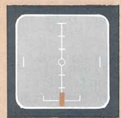
No Station Tuned
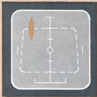
Off-Tune Left
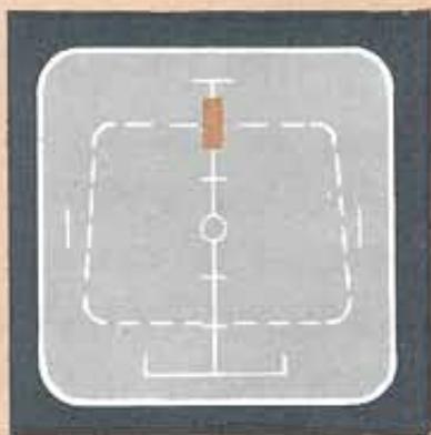
Correctly Tuned
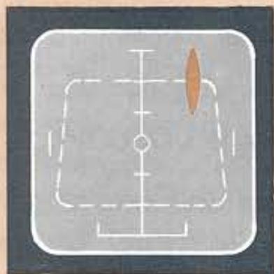
Off-Tune Right
Figure 8. FM Tuning Display
lows an approximate rectangular path, as indicated in Figure 8.
Signal strength is indicated by the relative vertical displacement of the trace. A trace near the top of the screen indicates greater signal strength than a lower trace.
Horizontal movement of the trace shows center tuning. For correct tuning, the trace should be centered on the upper portion of the oscilloscope as illustrated in Figure 8. Weak, distant stations will register horizontal deflection although there is little or no vertical deflection. Such stations can be visually tuned in even when below the muting threshold. Re-orientation of the antenna will often increase the signal strength sufficiently to improve reception.
AM TUNING DISPLAY:
With both TUNING SCOPE DISPLAY and AM pushswitches depressed, a short horizontal trace will appear in the lower part of the oscilloscope. As you tune past each AM station, this trace will move up and down. As with FM tuning, vertical deflection corresponds to signal strength. For correct tuning the trace should indicate the maximum vertical deflection. See Figure 9.
FM MULTIPATH INDICATION:
With both MULTIPATH SCOPE DISPLAY and FM pushswitches depressed, the trace on the oscilloscope will indicate FM broadcast modulation and multipath distortion characteristics.
FM Modulation characteristics (without multipath distortion) are shown in Figure 10. The amount of modulation or deviation is shown by the instantaneous horizontal expansion and contraction of the trace from its central point. The maximum deviation (expansion) permitted by the FCC is 75kHz , indicated by the widest grid lines printed near the bottom of the screen. If an FM station flagrantly over-modulates (grossly exceeds the 75kHz deviation limits), an excessively long
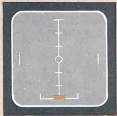
No Station Tuned
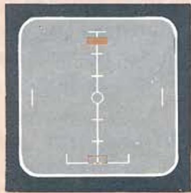
Correctly Tuned
Figure 9. AM Tuning Display
horizontal trace will result, with ends bending downwards, outlining the top of the IF passband characteristics of the tuner section. Although this will rarely happen, this oscilloscope function will show that the source of distortion is the transmitter, not the receiver.
The trace on the oscilloscope will also indicate when the antenna is oriented in the best possible direction to minimize multipath. A snake-like or distorted, trace (rather than the relatively smooth horizontal line shown in Figure 11A indicates that the antenna is pointed in an unfavorable direction for good reception from the station. It shows the multipath reflections as bumps on the normally-smooth line.
For best reception from each station, rotate the antenna to the direction giving the smoothest and most horizontal trace indication, even though this antenna orientation may not be the same as for the strongest signal (maximum vertical deflection).
The long, gentle trace of illustration B is preferable to those of illustrations C through G and should yield good reception. In turn, trace G indicates very poor antenna orientation, causing signal cancellation and unacceptable noise and distorted reception.
AUDIO DISPLAY SWITCH:
It occasionally happens by accident or intent that a selection is transmitted monophonically during a stereo program. This sudden loss of stereoseparation might cause some misgivings to the
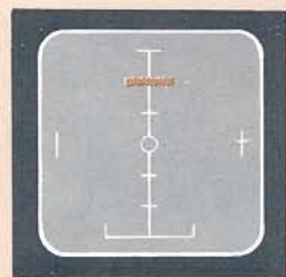
Pianissimo Passage or Pause In Program
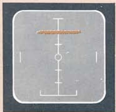
Loud Passage (Full Modulation)
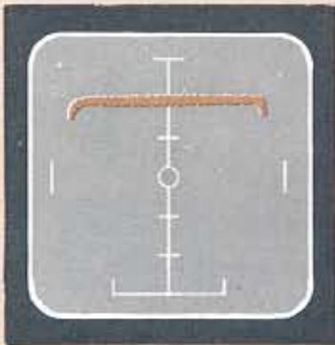
Over Modulation by Transmitter Causes Distortion
Figure 10. FM Modulation Characteristics
Listener if it were not for a simple test built into the Model 2130.
The test is initiated by depressing the AUDIO DISPLAY pushswitch and adjusting the scope LEVEL control. A display of left and right audio channels is presented in place of the normal tuning trace. Left channel audio corresponds to vertical motion; right channel to horizontal. The resultant pattern is an "X-Y plot" or Lissajous figure which is not only fascinating to watch, but also informative. By using the examples in Figure 12, you can quickly analyze the program material.
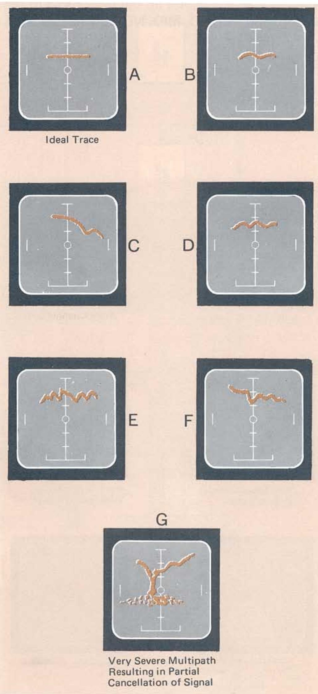
Figure 11. Multipath Distortion Characteristics
EXTERNAL AUDIO SCOPE DISPLAY:
Audio signals originating from other components in your audio system (phonographs, tape decks, microphones, etc.) can be displayed on the oscilloscope built into the Model 2130. Connect the scope outputs on the preamplifier or amplifier to the SCOPE INPUT on the Model 2130.
Depress the EXT switch to obtain a visual display of the stereo source signal on the scope and then adjust the EXT LEVEL control to keep the display within the boundaries of the face of the scope tube.
The display will not be affected by any of the mode selection switches on the front panel of the Model 2130 (MONO, MPX NOISE FILTER, etc.)
Left Channel Only
Right Channel Only
Zero Separation (Monophonic)
Both Channels (Maximum Separation)
Passage with Less Separation, such as Centrally Placed Soloist
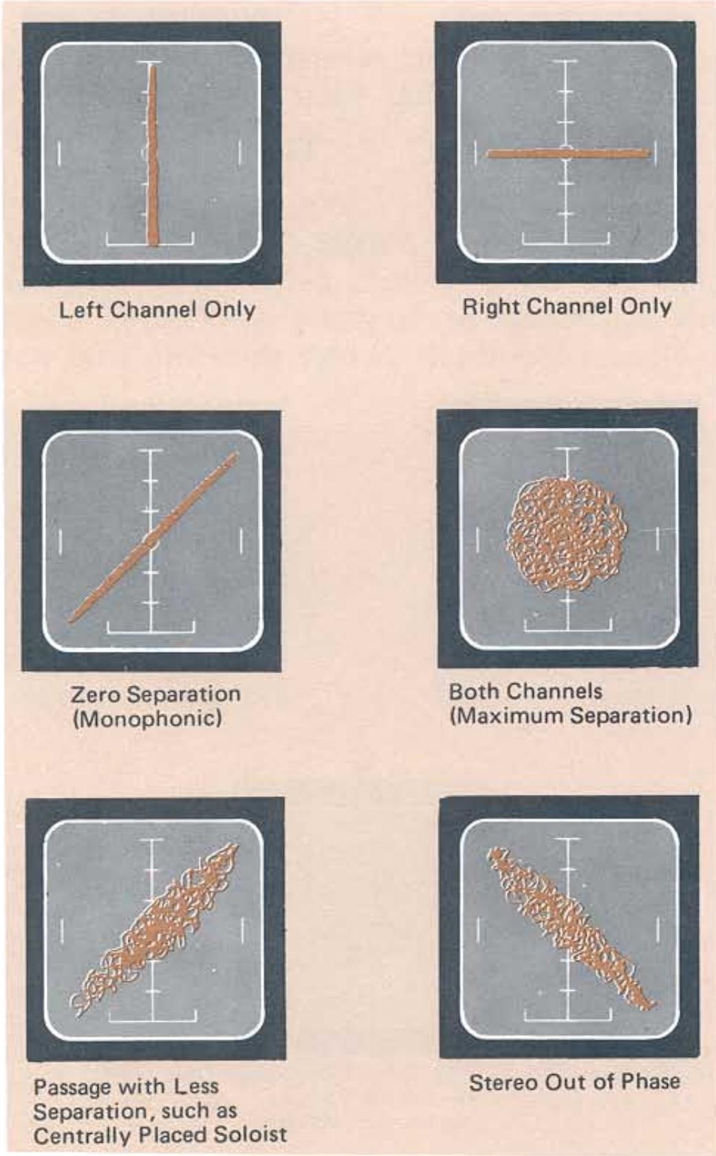
Stereo Out of Phase
Figure 12. Audio Display
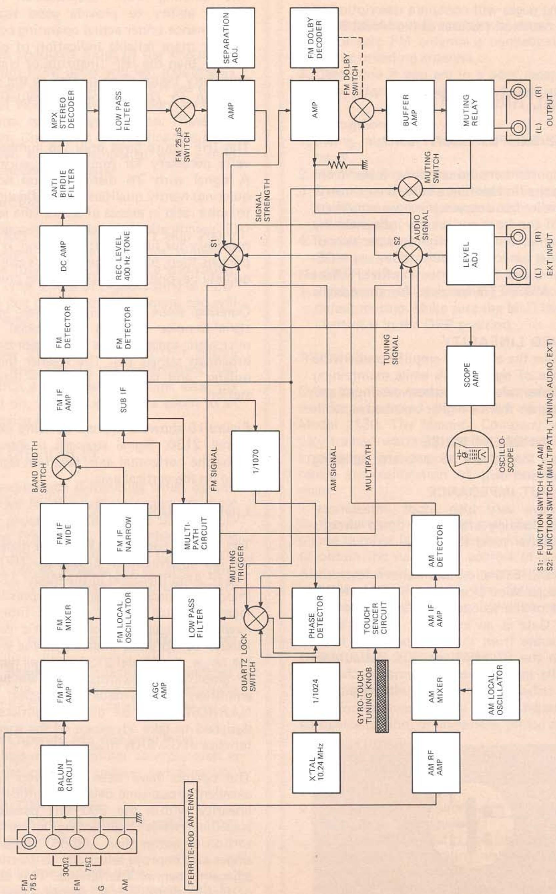
Figure 13. Functional Block Diagram
TECHNICAL SECTION
The following pages will contain a description of some of the technical features of the Model 2130.
TECHNICAL HIGHLIGHTS
DUAL GATE MOSFET FRONT END
One very important area of any tuner is its "front end". This is the first section of the tuner through which the radio frequency signals are amplified. The design of the front end greatly influences the sensitivity, noise, and selectivity characteristics of the tuner. Most tuners being built today use MOSFETS (Metal Oxide Semiconducting Field Effect Transistors). MOSFETS are used for three basic reasons:
(1) IMPROVED LINEARITY
MOSFETS have the ability to amplify over a wide dynamic range of signal levels while maintaining the correct linear relationships between input and output. This gives them a higher overload capability.
(2) LOWER INHERENT NOISE
These devices contribute to a better quieting slope (see next section).
(3) HIGH INPUT IMPEDANCE
MOSFETS have very high input impedances, which reduce loading effects on tuned circuits and result in better tuning selectivity.
Dual Gate MOSFETS allow additional refinement of the characteristics already available in MOSFETS by use of the second Gate (see Figure 14). The second Gate is an individual control input which is separate from the RF input. This isolation between the RF signal circuits and control circuits results in improved performance characteristics by reducing any loading effects on the RF tuned circuits.
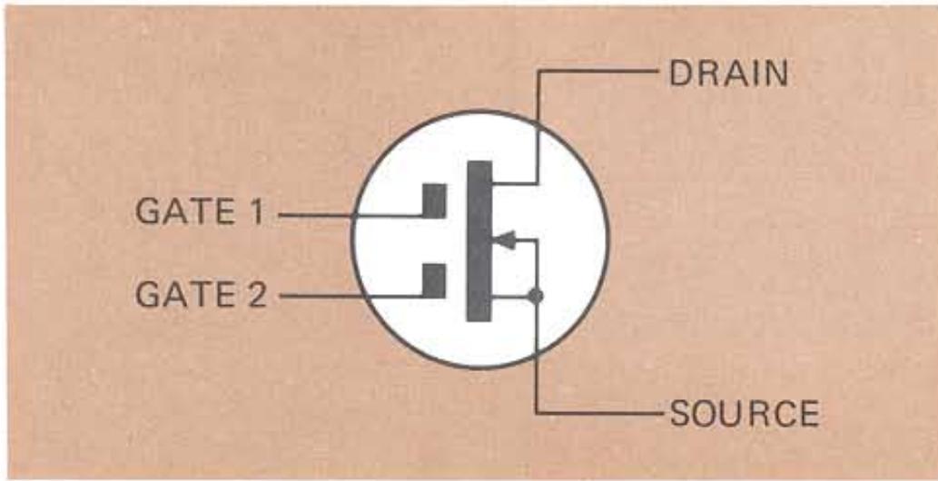
Figure 14. Dual Gate MOSFET
QUIETING SLOPE
The quieting slope specification measures a tuner's ability to provide good signal-to-noise performance under actual operating conditions. It is a far more reliable indication of performance quality than the IHF (Institute of High Fidelity) sensitivity figure often quoted as the prime specification to consider when evaluating an FM tuner.
The IHF figure gives only the number of microvolts necessary for minimum quality reception: A signal with 3% distortion and noise (30 dB quieting) hardly qualifies as high fidelity. A signal-to-noise ratio in excess of 50 dB (the revised 1975 IHF specification) is generally recognized to be necessary for high quality listening. It is most important then, to examine a tuner's ability to quiet quickly beyond the 30 dB quieting point.
Quieting slope sensitivity figures measure the signal-to-noise ratio in the crucial five-to-500 microvolt range, where the majority of usable broadcast signals fall. The steeper the slope, the quieter, and therefore the more listenable, the station.
Figure 15 shows a typical quieting slope for the Model 2130. Signal strength is shown graphed along the horizontal axis; resultant signal-to-noise ratio on the vertical axis.
LINEAR PHASE IF SECTION
The performance of an FM tuner depends greatly on the Intermediate Frequency (IF) amplifier. The IF Amplifier used in the Model 2130 includes integrated circuits designed expressly for FM reception, dual-element ceramic filters and two newly-developed Surface Acoustic Wave (SAW) filters. To optimize linearity of the widest possible range, the Model 2130 features two selectable IF amplifier bandwidths. There are two separate amplifiers for each mode of operation - WIDE and NARROW. Each of these amplifiers has been designed to take advantage of the special characteristics of the SAW filter.
The circuits have been optimized to maintain excellent group-time delay, amplitude, and phase linearity within the 200kHz passband of the amplifier, while maintaining an ultra-low distortion of better than -66dB . The sharp cutoff slopes also improve selectivity to greatly minimize adjacent channel interference. This combination of factors permits clear reception even when stations are spaced closely together on the dial.
PARAMETRIC MUTING CIRCUIT
The Model 2130 features a specially-designed Parametric Muting Circuit. Tuning across the dial is made virtually noise-free by this circuit which, by responding to received signal strength, multipath, and de-tuning of the detector assures positive audio muting action even under the most adverse conditions.
QUARTZ LOCKED SYSTEM
The 10.7 MHz signal from the I.F. Section is fed into a divide-by-1,070 frequency division circuit in the Quartz Locked System. The resultant signal then is 10.7MHz÷ 1,070 or 10.0kHz . The output of the Quartz Crystal Oscillator, whose frequency is 10.24MHz , is fed into a divide-by-1,024 frequency division circuit. The resultant then is 10.24MHz÷ 1,024 or 10.0kHz . These two signals are fed into a comparator. If there is any difference between the two signals, the comparator will generate an offset voltage which will then be fed into a variable capacitance diode located in the front end. This change in capacitance of this diode will shift the frequency of the front end to match the frequency of the radio station.
For example, imagine that the station is incorrectly tuned 10kHz higher than the optimum frequency of the station. The frequency from the I.F. would no longer be 10.7MHz but 10.71MHz . This would be divided down (as described above) to 10.009kHz . When this signal is presented to the comparator, the difference between the two frequencies (.009 kHz or 9 Hz) would generate an error correction voltage that would "shift" the tuning of the receiver to exactly match the frequency of the radio station.
STEREO DEMODULATOR
The Stereo Demodulator in the 2130 incorporates an integrated circuit (I.C.) of advanced design, which uses phase locked loop (PLL) and negative feedback (NFB) techniques for the demodulation process. Maximum stereo separation is achieved by this design, together with extremely low values of Total Harmonic Distortion (THD) in the decoded output signals.
The 2130 also incorporates a unique pilot cancelling circuit. This circuit provides out of phase signals which cancel any 19kHz residual signals and prevents these signals being present at the output
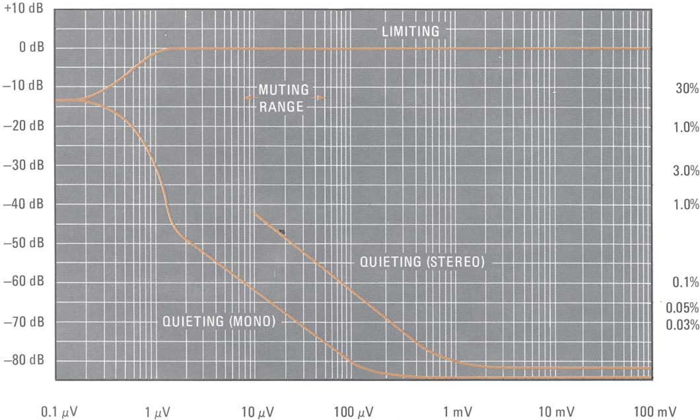
Figure 15. Quieting Slope
of the demodulator. The circuit automatically compensates for any changes in the amplitude of the 19kHz pilot signal transmitted by the station, to ensure that the out of phase signals are always at the precise amplitude necessary to achieve pilot cancellation. The elimination of residual pilot signals by this circuit, is far superior to the low pass filters used in many tuners for this purpose and the pilot cancellor circuit enables a flat frequency response to be maintained at the high end of the tuner's audio frequency band.
The PLL I.C. in the stereo demodulator circuit is equipped with an automatic stereo-monaural switching circuit. The circuit examines the input signal intensity and actuates the stereo demodulator and STEREO indicator lamp when the input signal is of sufficient strength to provide high quality stereo reception. When the input signal strength is insufficient for this purpose, the stereo signal is automatically changed to a monaural signal to ensure quality reception and a high signal-to-noise ratio.
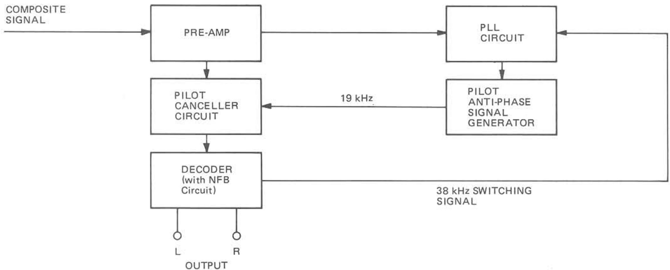
Figure 16. Pilot Cancelling Circuit
MAINTENANCE
CLEANING
The satin gold anodized finish of the knobs and heavy aluminum front panel will last indefinitely with proper care and cleaning. NEVER use scouring pads, steel wool, scouring powders, or harsh chemical agents, such as lye solution. These will mar the finish. Clean with a soft, lint-free cloth or cotton swab slightly dampened with a mild solution of detergent and water.
FUSE REPLACEMENT
The Model 2130 is protected by a 1 amp 250V fuse. In the event the fuse blows out, replace it ONLY with a fuse of the same type and rating. Replacement with a fuse of higher rating or slower action will not protect the instrument and will void the warranty.
The unit power should be switched OFF before replacing the fuse. Should the replacement fuse blow out within a short period of time after the unit is turned on, the unit should be taken to an authorized service facility.
IN CASE OF DIFFICULTY
Should you experience difficulties when operating your system for the first time, and you have followed the procedure outlined in the "Simplified Operating Procedure", use of the following data will help you correct or isolate the problem. If these hints fail to remedy the situation, refer the problem to your nearest authorized service facility.
Tuner does not operate, and dial lamps do not illuminate.
- Make sure power cord is properly connected.
- Check AC line fuse; replace if necessary (the unit should be OFF when replacing fuse).
Tuner does not operate, but dial lamp is on.
- Check settings of preamplifier controls such as selector, tape monitor, speaker switches, volume, power, etc.
- Turn off MUTING LEVEL.
- Check connection of shielded cables from tuner to preamplifier.
Tuner operates in one channel only.
- Turn off system power and transpose (left for right) the shielded cable at the tuner OUTPUT. If no sound is heard from the same speaker as
before, then either the input cable, integrated amplifier or preamplifier, or speaker system is at fault.
FM reception sounds scratchy or raspy.
- Make sure FM antenna is connected properly.
- Try re-orienting antenna.
- Determine if you are in a poor reception area. If so, refer to "Outdoor FM Antennas" section.
AM reception poor.
- Swing out AM Ferrite-rod antenna on rear panel.
- Re-orient the Ferrite-rod antenna.
- Determine if other components in your system, appliances, or fluorescent lights are causing interference.
- Try an outdoor antenna.
No 400 Hz tone.
- Signal strength of incoming signal too weak to defeat muting. Make sure the MUTING LEVEL Control is in the OFF position.
REPAIRS
Only the most competent and qualified service technicians should be allowed to service the Model 2130. The Marantz Company and its factory-trained warranty station personnel have the knowledge and special equipment needed for repair and calibration of this precision instrument.
In the event of difficulty, call the toll free telephone number listed on the back of the Warranty to obtain the name and address of the Marantz Authorized Service Station nearest your home or business. In many cases, the dealer where you purchased your Marantz unit will be equipped to provide service.
REPACKING FOR SHIPMENT
Should it become necessary to repack your Model 2130 for shipment to the factory, to an authorized service station, or elsewhere, please observe the following precautions:
a. Do not ship the unit installed in its accessory walnut cabinet; remove the unit from the cabinet before packing.
b. Pack the unit carefully, using the original material as shown in Figure 17.
PLEASE NOTE that if you have discarded, lost, or damaged the packing material, new packing material may be obtained by writing to the Marantz Technical Services Department. The carton, its fillers, and packing instructions will be returned to you at a nominal charge.
c. Ship via a reputable carrier (do not use Parcel Post) and obtain a shipping receipt from the carrier.
d. Insure the unit for its full value.
e. Be sure to include your return address on the shipping label.
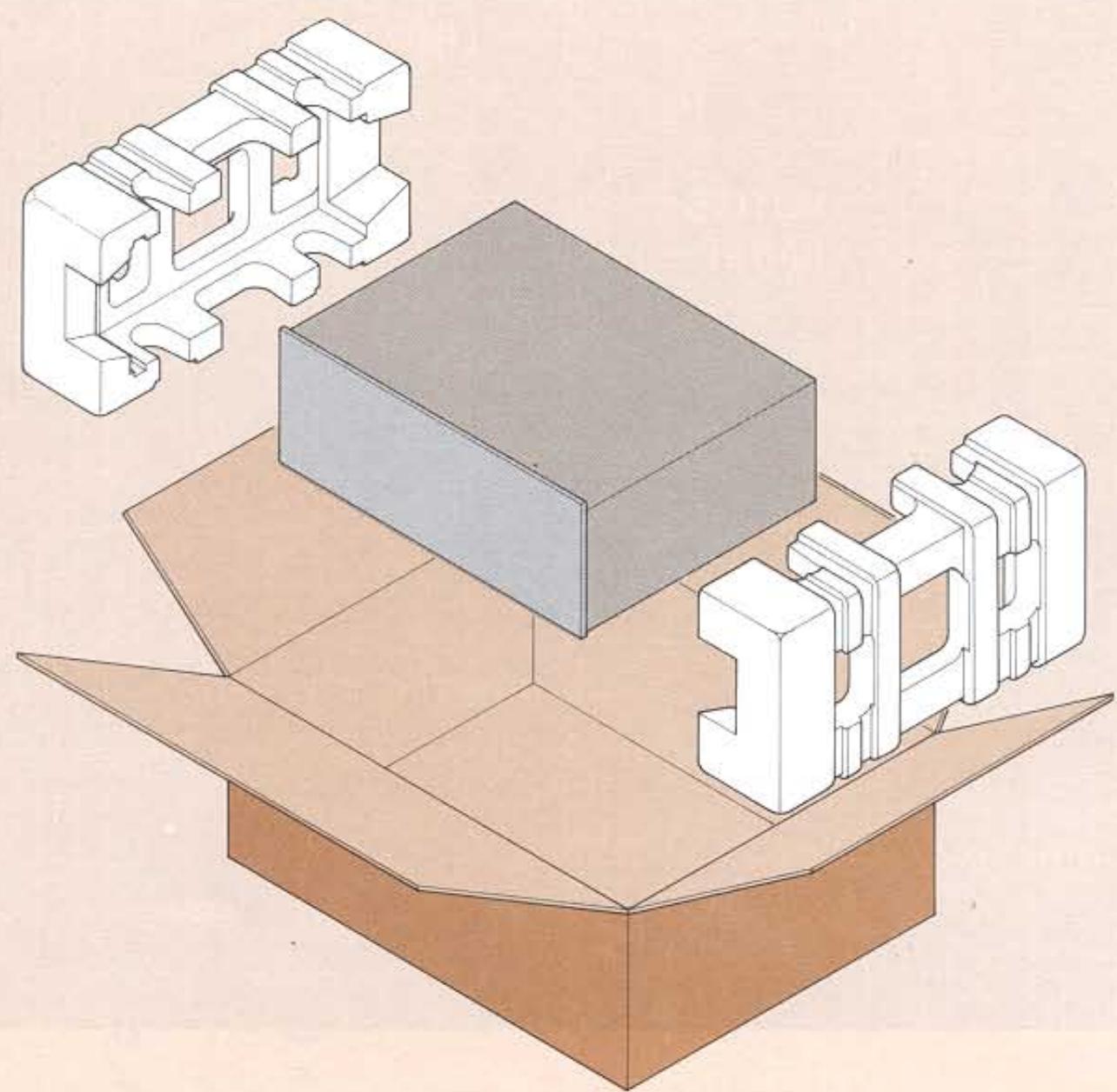
Figure 17. Repacking Illustration
The Sound of Marantz
is the compelling warmth of a Stradivarius.
It is a dancing flute, a haughty bassoon
and the plaintive call of a lone French horn.
The Sound of Marantz is the sound of beauty,
and Marantz equipment is designed to bring you
the subtle joy of its delight.
Wonderful adventures in sound await you
when you discover that the Sound of Marantz
is the sound of music at its very best.

mmamn
MODEL 2130 TECHNICAL SPECIFICATIONS
FM Tuner Section:
Sensitivity
IHF Usable 8.75 dBf (1.5 V)
IHF 50 dB Quieting (Mono) 12.1 dBf (2.2 V)
(Stereo) 33.2 dBf (25 V)
Quieting Slope (Mono)
RF Input for 30 dB Quieting 6.8 dBf (1.2 V)
Quieting at:
20 dBf (5.5 μV) 60 dB
25 dBf (10 μV) 66 dB
40 dBf ( 55 μV) 78 dB
65 dBf (1000 μV) 83 dB
Quieting Slope (Stereo)
Quieting at:
30 dBf ( 17 μV) 49 dB
40 dBf ( 55 μV) 62 dB
50 dBf (173 μV) 70 dB
65 dBf (1000 μV) 76 dB
Distortion (Mono) at 65 dBf (1000 V)
100 Hz . . . . . . . . . . . . . . . . . . . . . . . . . . . . . . . . . . . . . . . . . . . . . . . . . . . . . . . . . . . . . . . . . . . . . . . . . . . . . . . . . . . . . . . NARROW: 0.07%, WIDE: 0.05%
1000 Hz . . . . . . . . . . . . . . . . . . . . . . . . . . . . . . . . . . . . . . . . . . . . . . . . . . . . . . . . . . . . . . . . . . . . . . . . . . . . . . . . . . . . . NARROW: 0.07%, WIDE: 0.05%
6000 Hz . . . . . . . . . . . . . . . . . . . . . . . . . . . . . . . . . . . . . . . . . . . . . . . . . . . . . . . . . . . . . . . . . . . . . . . . . . . . . . . . . . . . . . . NARROW: 0.13%, WIDE: 0.1%
Distortion (Stereo) at 65 dBf (1000 V)
100 Hz . . . . . . . . . . . . . . . . . . . . . . . . . . . . . . . . . . . . . . . . . . . . . . . . . . . . . . . . . . . . . . . . . . . . . . . . . . . . . . . . . . . . . . . NARROW: 0.20%, WIDE: 0.09%
1000 Hz . . . . . . . . . . . . . . . . . . . . . . . . . . . . . . . . . . . . . . . . . . . . . . . . . . . . . . . . . . . . . . . . . . . . . . . . . . . . . . . . . . . . NARROW: 0.15%, WIDE: 0.07%
6000 Hz . . . . . . . . . . . . . . . . . . . . . . . . . . . . . . . . . . . . . . . . . . . . . . . . . . . . . . . . . . . . . . . . . . . . . . . . . . . . . . . . . . . . . . NARROW: 0.30%, WIDE: 0.20%
Distortion (Mono and Stereo)
at 50 dB Quieting, 1000 Hz 0.4%
Hum and Noise
at 65 dBf (1000 μV)
Mono 80 dB
Frequency Response
30 Hz to 15 kHz
Mono +0.2-1.0 dB
Stereo . 0.2 , - 1.0 dB
Capture Ratio
at 65 dBf (1000 μV) . . . . . . . . . . . . . . . . . . . . . . . . . . . . . . . . . . . . . . . . . . . . . . . . . . . . . . . . . . . . . . . . . . . . . . . . . . . . . . . . . . . . NARROW: 1.5 dB, WIDE: 0.8 dB
Alternate Channel Selectivity . . . . . . . . . . . . . . . . . . . . . . . . . . . . . . . . . . . . . . . . . . . . . . . . . . . . . . . . . . . . . . . . . . . . . . . . . . . . . . . NARROW: 85 dB, WIDE: 45 dB
Spurious Response Rejection 120 dB
Image Response Rejection 120 dB
I.F. Rejection (Balanced) 120 dB
A.M. Suppression 65 dB
Stereo Separation
100 Hz . . . . . . . . . . . . . . . . . . . . . . . . . . . . . . . . . . . . . . . . . . . . . . . . . . . . . . . . . . . . . . . . . . . . . . . . . . . . . . . NARROW: 45 dB, WIDE: 45 dB
1000 Hz . . . . . . . . . . . . . . . . . . . . . . . . . . . . . . . . . . . . . . . . . . . . . . . . . . . . . . . . . . . . . . . . . . . . . . . . . . . . . . NARROW: 50 dB, WIDE: 55 dB
10 kHz . . . . . . . . . . . . . . . . . . . . . . . . . . . . . . . . . . . . . . . . . . . . . . . . . . . . . . . . . . . . . . . . . . . . . . . . . . . . . . . . NARROW: 42 dB, WIDE: 45 dB
Subcarrier Rejection 75 dB
AM Tuner Section:
IHF Usable Sensitivity 10 uV
Distortion (THD), 30% Modulation . . . . . . . . . . . . . . . . . . . . . . . . . . . . . . . . . . . . . . . . . . . . . . . . . . . . . . . . . . . . . . . . . . . . . . . . . . . 0.4%
Signal-to-Noise Ratio 55 dB
Alternate Channel Selectivity 50 dB
Image Rejection 80 dB
Spurious Response Rejection 90 dB
I.F. Rejection 80 dB
General:
Power Requirements 120 V AC, 60 Hz
Power Consumption 30 W
Dimensions:
Panel Width 416 mm (16-3/8 inches)
Panel Height 146 mm (5-3/4 inches)
Depth 301 mm (11-7/8 inches)
Weight:
Unit alone 9 kg (19.8 lbs)
Packed for shipment 11 kg (24.2 lbs)
Limited Warranty
Marantz Company, Inc. proudly warrants Marantz products to be free of manufacturing defects in material and workmanship as follows:
| Product | Duration of Warranty | |
| Parts | Labor | |
| Receivers*, Tuners*, Amplifiers, Tape Decks, Turntables** and Electronic Accessories | 2 Years | 2 Years |
| Speaker Systems (including Cabinets) | 5 Years | 5 Years |
| Car Stereo Radios, Tape Players, Radio/Tape Combinations, Tuners and Power Amplifiers | 1 Year | 90 Days |
| Car Stereo Speaker Systems | 1 Year Exchange | |
| Accessories (including Cabinets and Rack Adapters) | 90 Days | 90 Days |
Oscilloscope tubes and labor for repair or replacement are warranted for only ninety (90) days from date of purchase.
*Drive belts and labor for repair or replacement are warranted for only ninety (90) days from date of purchase.
Stylus and cartridge are not warranted.
NO WARRANTY, WHETHER EXPRESS OR IMPLIED, IS GIVEN OR MADE WITH RESPECT TO ANY ACCESSORY SUPPLIED WITH PRODUCTS DESCRIBED ABOVE.
This Warranty and the extent of the responsibility of Marantz Company, Inc. hereunder are subject to the following conditions and limitations:
If your Marantz product should prove defective in material or workmanship within the prescribed period from date of purchase, Marantz Company, Inc. will repair or replace the product, in its sole discretion, without charge, upon presentation of satisfactory proof of purchase. (It is the responsibility of the consumer to establish proof and date of purchase; the purchase receipt or invoice is adequate for such proof.)
THIS IS NOT A SERVICE CONTRACT. THIS WARRANTY DOES NOT INCLUDE MAINTENANCE, CLEANING, PERIODIC CHECK-UP OR CHARGES INCurred FOR REMOVAL OR REINSTALLATION OF PRODUCT.
For Warranty service, simply follow the instructions on the reverse side of this Warranty.
This Warranty is void if the serial number has been altered or removed from a serialized product; if the product is modified in any manner which Marantz concludes, after inspection, affects the reliability of the product; if the product has been repaired or serviced by anyone other than an AUTHORIZED Marantz Service Station; if the product is damaged because not properly installed, maintained or operated in accordance with the instructions which accompany the product.
Marantz Company, Inc. reserves the right to make changes in design and/or improvements upon its products without any obligation to include these changes in any products theretofore manufactured.
TO THE EXTENT NOT IN CONFLICT WITH APPLICABLE LAW, THIS WARRANTY EXTENDS ONLY IN FAVOR OF THE ORIGINAL PURCHASER AND SHALL BE VALID ONLY IF THE PRODUCT IS PURCHASED AND WARRANTY SERVICE SOUGHT WITHIN THE UNITED STATES OF AMERICA, INCLUDING POSSESSIONS AND TERRITORIES. EXCEPT TO THE EXTENT PROHIBITED BY APPLICABLE LAW, ALL IMPLIED WARRANTYES MADE BY MARANTZ IN CONNECTION WITH THIS PRODUCT INCLUDING WARRANTYES OF MERCHANTABILITY OR FITNESS ARE LIMITED IN DURATION TO THE WARRANTY PERIOD SET FORTH ABOVE, AND NO WARRANTYIES WHETHER EXPRESS OR IMPLIED, INCLUDING WARRANTYES OF MERCHANTABILITY OR FITNESS, SHALL APPLY TO THIS PRODUCT AFTER SAID PERIOD HAS EXPIRED. THE CONSUMER'S SOLE REMEDY SHALL BE REPAIR OR REPLACEMENT AS IS EXPRESSLY PROVIDED ABOVE; AND UNDER NO CIRCUMSTANCES SHALL MARANTZ BE LIABLE FOR ANY LOSS OR DAMAGE, DIRECT OR CONSEQUENTIAL, ARISING OUT OF THE USE OF, OR INABILITY TO USE, THIS PRODUCT.
Some states do not allow limitations on how long an implied warranty lasts or the exclusion or limitation of incidental or consequential damages, so the above limitations or exclusion may not apply to you. This warranty gives you specific legal rights, and you may also have other rights which vary from state to state.
Marantz Company, Inc. is a wholly-owned subsidiary of Superscope Inc., 20525 Nordhoff Street, Chatsworth, California 91311.
INSTRUCTIONS FOR OBTAINING WARRANTY SERVICE
- For Warranty service, send the product to the Marantz Branch Service Center nearest you. Refer to paragraph 4 for shipping instructions and to the list of Branch Service Centers below.
MARANTZ BRANCH SERVICE CENTERS
CALIFORNIA
California Service Center
20525 Nordhoff Street
Chatsworth, California 91311
San Diego Service Center
6506 El Cajon Blvd.
San Diego, California 92115
ILLINOIS
Superscope Chicago, Inc.
1300 Norwood Avenue
Itasca, Illinois 60143
MICHIGAN
Superscope Detroit, Inc.
591 Executive Drive
Troy, Michigan 48084
NEW YORK METROPOLITAN AREA
Superscope New York, Inc.
56-08 37th Avenue
Woodside, New York 11377
TEXAS
Superscope Texas, Inc.
3214 Beltline Road
Dallas, Texas 75234
WASHINGTON
Superscope Northwest, Inc.
12842 N.E. 15th Place
Bellevue, Washington 98005
- In the event no Marantz Branch Service Center is located near you, dial the following toll free numbers and the operator taking your call will provide you with the name and address of one or more Authorized Marantz Service Stations located near you in the continental United States.
Call toll free 800-447-1970 (In Illinois 800-322-0800)
- For Alaska and Hawaii, dial the following toll free number for the location of your nearest Authorized Marantz Service Station:
Call toll free 800-447-0890
- If you decide to ship the product for Warranty service, please make sure you follow these additional instructions. All shipping charges must be prepaid. If the requested repairs or service (including parts replacement) are within the terms of the Warranty, Marantz will pay return shipping charges only to a designated point within the United States, including the District of Columbia. If warranty service is requested, enclose proof of purchase (such as copy of your dated purchase receipt.) If the entire instrument is sent, it must be shipped in its original package. No accessories should be shipped with the product. If any accessories are shipped with the product, Marantz shall have no liability whatsoever for loss of or damage to any such accessories, nor for the safe return thereof.
- Do not dispose of this Warranty after it expires. In the event your product requires future service or repair after expiration of the Warranty, these instructions should be followed to enable you to obtain proper service which, of course, will be at your expense.
FROM

IMPORTANT
PLEASE PRINT YOUR NAME AND ADDRESS
(This is your shipping label)
ENIN70

3N170

LNEWJRAHdSdVNOIJA
LL6
H
SFOHONGZ902
AIDSLRdREWNSNO
Punos
:01
3H3H
72.14
3
OPEN HERE
CUSTMERSO PRDFTED
For mharantz, ACCESSORIES
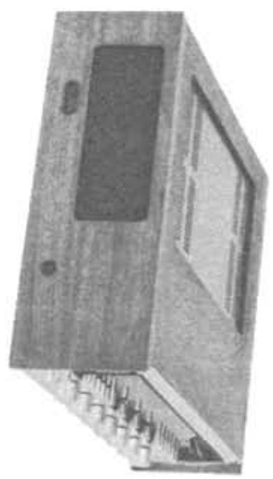
WALNUT CABINETS
PLUG-IN ADAPTORS
RACKHANDLES
Check here if you wish information regarding Marantz extended service contract.
NO CASH or C.O.D.'s please.
for model
1090.1
for most
SB
Dolby EM* adaptor for
Full Logic SC
for models 1090, 1122DC
170DC.
2238B, 2252B, 2265B
WC-121
WC-12
2506.
for mode 5025B,5
REMOTE
1 2007-07-03
2330B,4300,4400
WC-136 $24.
2120.
MODEL NUMBER OF YO MARANTZ UNIT
| WALNUT CABINETS | PLUG-IN ADAPTORS | RACK HANDLES | |||||||
| WC-110 | 29.95 | WC-116 | 29.95 | DLB-1 | 34.95 | SOA-2B | 79.95 | RHA-1 | 29.95 pr. |
| for models 1090, 1122DC, 1152DC, 1180DC, 170DC. | for models 2216, 2216B, 2215B | Dolby FM* adaptor for models 2120, 2140, 2238B, 2252B, 2265B, 2285B, 2330B, 2385, 2500. | Full logic SQ** adapter for models 4230, 4240, 4270, 4300, 4400 | for models 1090, 1122DC, 1152DC, 1180DC, 170DC, 3250, 2100, 2120, fits standard 19" rack. | |||||
| WC-121 | 24.95 | WC-122 | 32.95 | RHA-2 | 29.95 pr. | ||||
| for models 5010B, 5025B, 5030B | for models 2220B through 2285B and 4230 through 4270 | For models 5010B, 5025B, 5030B fits standard 19" rack. | |||||||
| REMOTE CONTROL | |||||||||
| WC-123 | 39.95 | WC-124 | 44.95 | Controls level and balance for all 4 channels. | RC-4 | 39.95 | CARTRIDGE SHELL | ||
| For models 2325, 2330, 2330B, 4300, 4400. | For models 2385, 2500. | For models 4230, 4240, 4270, 4300, 4400. | |||||||
| WC-136 | 24.95 | DOLBY* CALIBRATION TAPES | |||||||
| For models 3250, 2100, 2120. | Reel to Reel #897-5000-000 | 3.50 | |||||||
| Cassette #897-5001-000 | 4.95 | MHS-1 | 10.95 | ||||||
| Walnut Cabinets are shipped unassembled and are easily installed with the use of a screwdriver without the need to disconnect your unit. | 8-Track #897-5002-000 | 4.95 | Fits all Marantz turntables. Includes all mounting hardware. | ||||||

DOLBY* CALIBRATION TAPES
| MODEL NBR | @ | QTY | TOTAL |
| SUB TOTAL | |||
| Add State or local sales TAX, if applicable | |||
| HANDLING CHARGE | $1.00 | ||
| TOTAL ENCLOSED | |||
- Model 2130 AM/FM Stereophonic Tuner
- FOREWORD
- AFTER UNPACKING
- ABOUT THIS MANUAL
- PURCHASER'S RECORD
- IMPORTANT
- TABLE OF CONTENTS
- LIST OF ILLUSTRATIONS
- PREPARATION FOR USE
- MECHANICAL INSTALLATION
- MARANTZ WALNUT VENEER CABINET
- RACK ADAPTOR
- CUSTOM INSTALLATION
- SIGNAL CONNECTIONS
- OUTPUT JACKS
- AM ANTENNA
- FM ANTENNA
- OUTDOOR FM ANTENNAS
- OUTDOOR AM ANTENNA
- OPERATING POWER CONNECTION
- CONVENIENCE OUTLET
- AC PROTECTOR FUSE
- DOLBY PLUG-IN FM DECODER INSTALLATION
- SIGNAL CONNECTION CHECKLIST
- OPERATION
- SIMPLIFIED OPERATING PROCEDURES
- SIMPLIFIED SCOPE PROCEDURES
- FRONT PANEL FEATURES
- MONO SWITCH
- MPX NOISE FILTER SWITCH
- OUTPUT LEVEL CONTROL
- MUTING LEVEL CONTROL
- IF BANDWIDTH SWITCH
- QUARTZ LOCK SWITCH
- RECORD LEVEL TONE SWITCH
- FM 25 S SWITCH
- RECORDING DOLBYIZED FM PROGRAMS
- NOTE:
- OSCILLOSCOPE
- FOCUS AND BRIGHTNESS ADJUSTMENTS:
- FM TUNING DISPLAY:
- AM TUNING DISPLAY:
- FM MULTIPATH INDICATION:
- AUDIO DISPLAY SWITCH:
- EXTERNAL AUDIO SCOPE DISPLAY:
- TECHNICAL SECTION
- TECHNICAL HIGHLIGHTS
- DUAL GATE MOSFET FRONT END
- IMPROVED LINEARITY
- LOWER INHERENT NOISE
- HIGH INPUT IMPEDANCE
- QUIETING SLOPE
- LINEAR PHASE IF SECTION
- PARAMETRIC MUTING CIRCUIT
- QUARTZ LOCKED SYSTEM
- STEREO DEMODULATOR
- MAINTENANCE
- CLEANING
- FUSE REPLACEMENT
- IN CASE OF DIFFICULTY
- REPAIRS
- REPACKING FOR SHIPMENT
- MODEL 2130 TECHNICAL SPECIFICATIONS
- FM Tuner Section:
- Sensitivity
- Quieting Slope (Mono)
- Quieting at:
- Quieting Slope (Stereo)
- Distortion (Mono) at 65 dBf (1000 V)
- Distortion (Stereo) at 65 dBf (1000 V)
- Distortion (Mono and Stereo)
- Hum and Noise
- Frequency Response
- Capture Ratio
- Alternate Channel Selectivity . . . . . . . . . . . . . . . . . . . . . . . . . . . . . . . . . . . . . . . . . . . . . . . . . . . . . . . . . . . . . . . . . . . . . . . . . . . . . . . NARROW: 85 dB, WIDE: 45 dB
- Spurious Response Rejection 120 dB
- Image Response Rejection 120 dB
- I.F. Rejection (Balanced) 120 dB
- A.M. Suppression 65 dB
- Stereo Separation
- Subcarrier Rejection 75 dB
- AM Tuner Section:
- General:
- Limited Warranty
- INSTRUCTIONS FOR OBTAINING WARRANTY SERVICE
- MARANTZ BRANCH SERVICE CENTERS
- PLEASE PRINT YOUR NAME AND ADDRESS
- CUSTMERSO PRDFTED
- For mharantz, ACCESSORIES
Marque : MARANTZ
Modèle : 2130
Catégorie : Récepteur audio-vidéo