
M185-107T - Tracteur de jardin MCCULLOCH - Notice d'utilisation et mode d'emploi gratuit
Retrouvez gratuitement la notice de l'appareil M185-107T MCCULLOCH au format PDF.

| Type d'appareil | Tracteur agricole |
| Modèle | Non précisé |
| Numéro de modèle | 96041037801 |
| Numéro de catalogue client | M185-107T |
| Numéro de produit | 960 41 03-78 |
| Révision | 4 |
| Type de moteur | Non précisé |
| Puissance moteur | Non précisé |
| Transmission | Non précisé |
| Capacité du réservoir | Non précisé |
| Poids | Non précisé |
| Dimensions (L x l x H) | Non précisé |
| Type de carburant | Non précisé |
| Nombre de cylindres | Non précisé |
| Vitesse maximale | Non précisé |
| Émissions | Non précisé |
FOIRE AUX QUESTIONS - M185-107T MCCULLOCH
Questions des utilisateurs sur M185-107T MCCULLOCH
0 question sur cet appareil. Repondez a celles que vous connaissez ou posez la votre.
Poser une nouvelle question sur cet appareil
Téléchargez la notice de votre Tracteur de jardin au format PDF gratuitement ! Retrouvez votre notice M185-107T - MCCULLOCH et reprennez votre appareil électronique en main. Sur cette page sont publiés tous les documents nécessaires à l'utilisation de votre appareil M185-107T de la marque MCCULLOCH.
MODE D'EMPLOI M185-107T MCCULLOCH
ILLUSTRATED PARTS LIST
MODEL NO. 96041037801
CUSTOMER CATALOG NO. M185-107T
PRODUCT NO. 960 41 03-78
KEY PART
NO. NO. DESCRIPTION
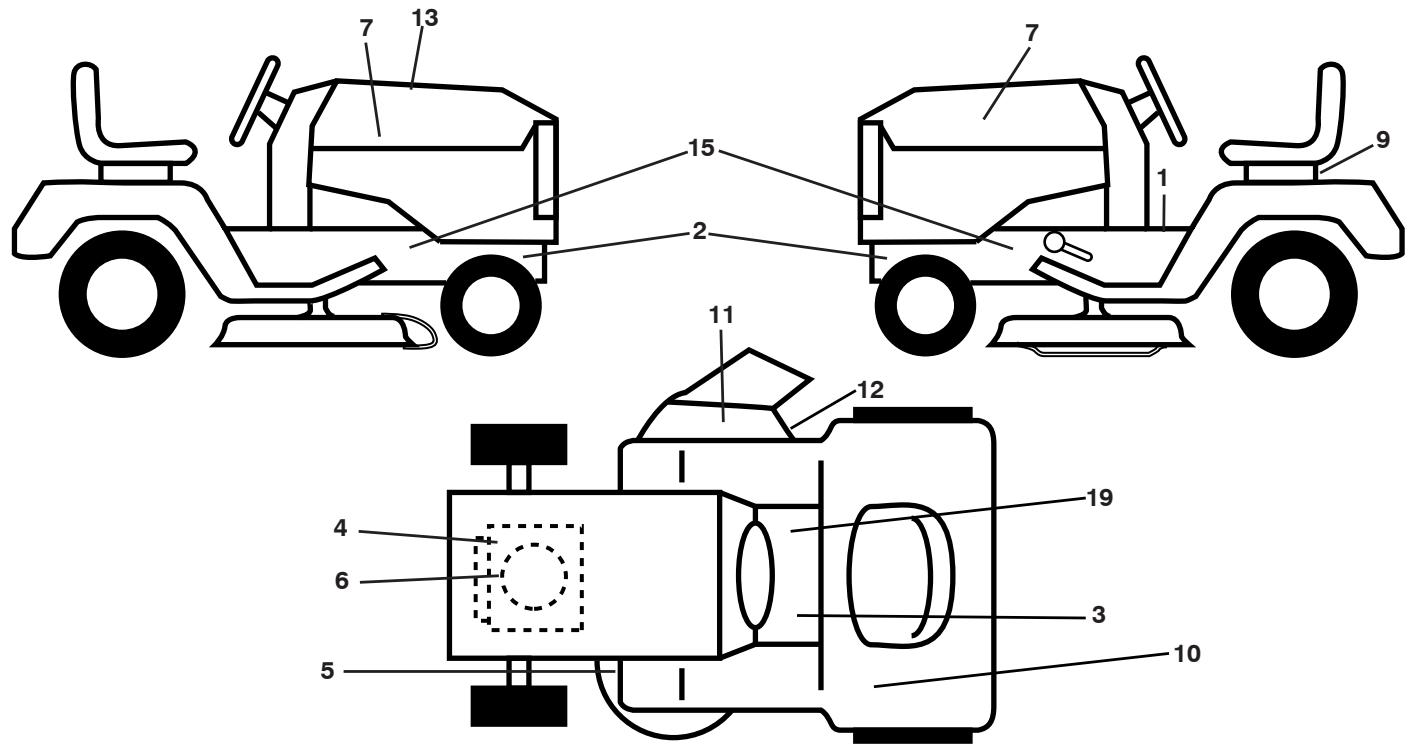
1 581 57 81-01 Decal, Warning Sym.
2 581 57 98-01 Decal, Warning Service/Fire
3 581 72 40-01 Decal, Saddle Brake Clutch
4 581 57 97-01 Decal, Warning Engine
5 581 58 00-01 Decal, V-Belt Sch.
6 532 43 74-20 Decal, Eng. HP
7 581 09 12-01 Decal, Hood LH/RH
9 532 14 50-05 Decal, Battery Dnge/Point
10 587 20 28-01 Decal, Fender Side
11 584 90 46-01 Decal, Deflect. Warning
12 581 57 92-01 Decal, Deflector Warning
13 581 59 18-01 Decal, Replacement
KEY PART
NO. NO.
15 581 57 96-01 Decal, Hot Muffler
19 581 57 80-01 Decal, Saddle Brake Parking
-- 5817248-01 Decal, Bypass
-- 5817246-01 Decal,Load Limit
-- 5324095-05 Pad,Footrest,LH
-- 5324095-07 Pad,Footrest,RH
-- 588 84 24-40 Manual,Operator's Euro
-- 588 84 24-50 Manual,Operator's Scan
-- 588 84 24-20 Manual,Operator's EBloc
-- 588 84 24-30 Manual,Operator's Baltic
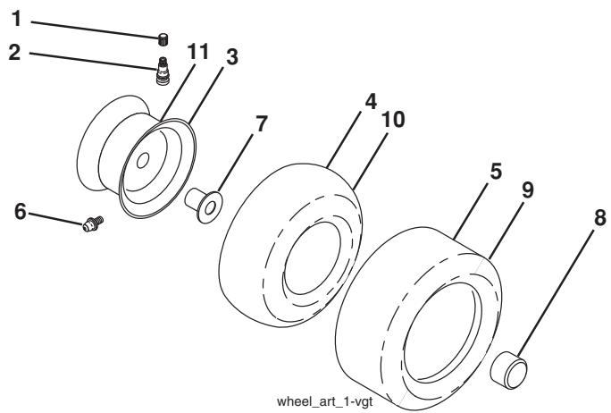
WHEELS AND TIRES
KEY PART
NO. NO.
1 5320591-92 Cap,Valve,Tire
2 5320651-39 Stem,Valve
3 532 12 51-21 Rim Assembly, Front
4 532 05 99-04 Tube, Front (Service Item Only)
5 532 10 62-22 Tire, Front 15 x 6-6
6 532 12 49-57 Fitting, Grease (Front Wheel Only)
7 532 12 49-59 Bearing, Flange (Front Wheel Only)
8 532 19 32-68 Cap, Axle
9 532 13 84-68 Tire, Rear 20 x 8-8
10 532 12 49-26 Tube, Rear (Service Item Only)
11 532 12 51-22 Rim Assembly, Rear
- - 532 14 43-34 Sealant, Tire (10 oz. Tube)
NOTE: All component dimensions given in U.S. inches. 1 inch = 25.4 mm
TRACTOR - - MODEL NO. M185-107T (96041037801), PRODUCT NO. 960 41 03-78
SCHEMATIC 38
SCH10
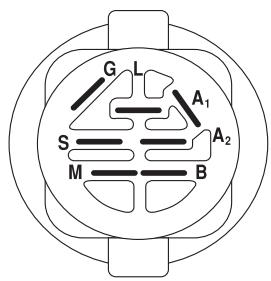
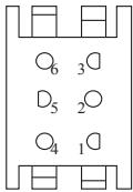
IGNITION SWITCH
| POSITION | CIRCUIT | “MAKE” |
| OFF | M+G+A1 | |
| RUN/OVERRIDE | B+A1 | |
| RUN | B+A1 | L+A2 |
| START | B + S + A1 |
03107
CHASSIS HARNESS
CONNECTOR
(MATING SIDE)
DASH HARNESSE
CONNECTOR
(MATING SIDE)
WIRING INSULATED CLIPS
NOTE: IF WIRING INSULATED
CLIPS WERE REMOVED FOR
SERVICING OF UNIT, THEY
SHOULD BE RE-INSTALLED TO
PROPERLY SECURE YOUR
WIRING.
N-REMOVALE
NECtions
MOVABLE
CONNECTIONS
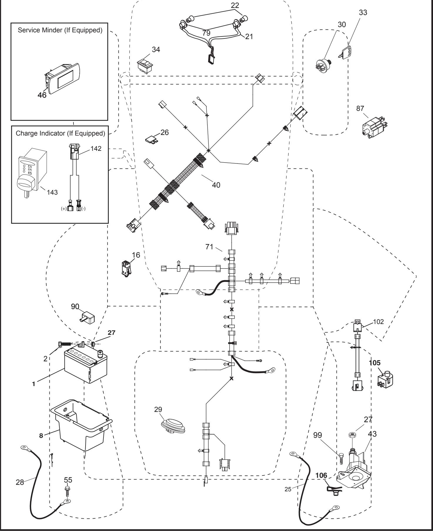
TR02S
KEY PART NO. NO.
| 1 | 532 16 34-65 |
| 2 | 874 76 04-12 |
| 8 | 532 19 32-28 |
| 16 | 532 17 61-38 |
| 21 | 532 40 02-52 |
| 22 | 532 00 41-52 |
| 25 | 581 49 80-01 |
| 26 | 532 17 51-58 |
| 27 | 873 51 04-00 |
| 28 | 532 42 16-86 |
| 29 | 532 40 15-45 |
| 30 | 532 19 33-50 |
| 33 | 532 41 19-35 |
| 34 | 532 11 07-12 |
| 40 | 581 02 31-01 |
| 43 | 532 19 25-07 |
| 55 | 817 06 05-12 |
| 71 | 501 13 37-01 |
| 79 | 532 17 52-42 |
| 87 | 532 19 78-02 |
| 90 | 532 43 53-95 |
| 99 | 817 67 04-12 |
| 102 | 581 02 34-01 |
| 105 | 532 40 75-68 |
| 106 | 532 17 48-14 |
DESCRIPTION
| Battery |
| Bolt Hex Hd 1/4-20 unc x 3/4 |
| Battery Box |
| Switch Interlock |
| Harness Socket Light |
| Bulb, Light # 1156 |
| Cable Starter |
| Fuse |
| Nut Keps Hex 1/4-20 unc |
| Cable Ground |
| Switch Seat |
| Switch Ign |
| Key/Chain |
| Switch Light/Reset |
| Harness Ign. Dash |
| Solenoid |
| Screw Thdrol 5/16-18 x 3/4 |
| Harness Ign. Chassis |
| Socket Asm. Bulb |
| Switch Interlock |
| Cover Terminal Battery |
| Screw 1/4-20 x 3/4 |
| Harness Pigtail |
| Switch Reverse |
| Palnut 1/4 Lugs |
NOTE: All component dimensions given in U.S. inches 1 inch = 25.4 mm
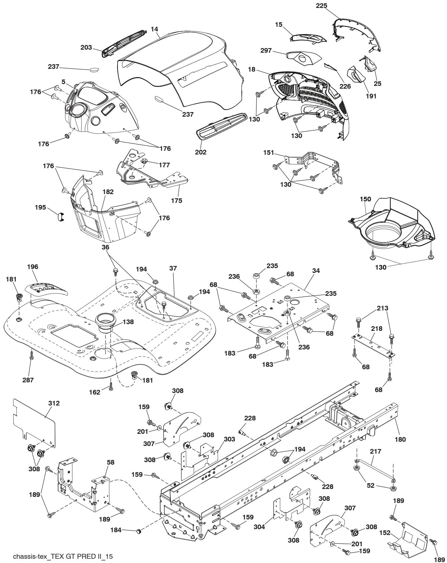
chassis-tex_TX GT PRED II_15
KEY PART
NO. NO.
DESCRIPTION
5 5324466-39
14 5324480-42
15 581 10 31-01
18 581 10 29-01
25 581 10 30-01
34 5809108-01
36 8170605-12
37 5324207-96
52 8736805-00
58 5324122-80
68 8174905-08
130 5324163-58
138 5324097-30
150 584 86 29-03
151 5324454-94
152 532 19 95-35
159 8170006-12
162 532 14 24-32
175 532 19 63-04
176 5324007-76
177 532 19 52-28
180 5324150-63
181 5324047-96
182 5867386-02
183 8745205-20
184 587 55 41-01
189 8170005-12
191 581 22 35-01
194 873 90 05-00
195 5324041-37
196 5324145-81
Dash
Hood
Lens LH
Grille
Lens RH
Plate Engine
Screw 5/16-18 x 3/4
Fender
Nut Crown Lock 5/16
Drawbar Upper
Screw THDROL 5/16-18 x 1/2
Screw
Cupholder
Air Duct
Bracket Pivot
Shield Browning
Screw 3/8-16 x 3/4
Screw 1 / 4 × 1 / 2
Crossmember
Screw 10-24 x 5/8
Bushing Steering
Chassis
Bushing Mtq. Fender Crgo
Dash Lower
Bolt 5/16-18 x 1-1/4
Plug
Screw 5/16-18 x 3/4
Reflector RH
Nut Lock Hex Flange 5/16-18
Plug Hole Dash Lower
Console Asm. Deck Lift
KEY PART
NO. NO.
DESCRIPTION
201 819 13 20-16
202 581 85 92-01
203 581 85 92-01
213 874 76 05-12
217 5324091-67
218 532 19 63-95
225 581 10 32-01
226 578 89 71-01
228 532 19 51-61 Stud Fastener
235 532 40 61-29 Spacer Fender
236 873 93 05-00 Nut Lock 5/16-18 unc
237 532 40 37-04 Plug Mount Cargo
287 817 60 04-06 Screw Hex Washead 1 / 4 - 20 × 3 / 8
297 581 22 36-01 Reflector LH
303 587 49 34-02 Shield Chassis French LH
304 587 86 51-02 Shield Chassis French RH
307 587 49 46-01 Shield Upper Pedal
308 532 17 18-77 Bolt 5/16-18 unc x 3/4
312 587 49 30-02 Shield Drawbar
-- 5324411-26 Plug Dash SRVMNDR.
-- 5324009-44 BumperKit
NOTE: All component dimensions given in U.S. inches 1 inch = 25.4 mm
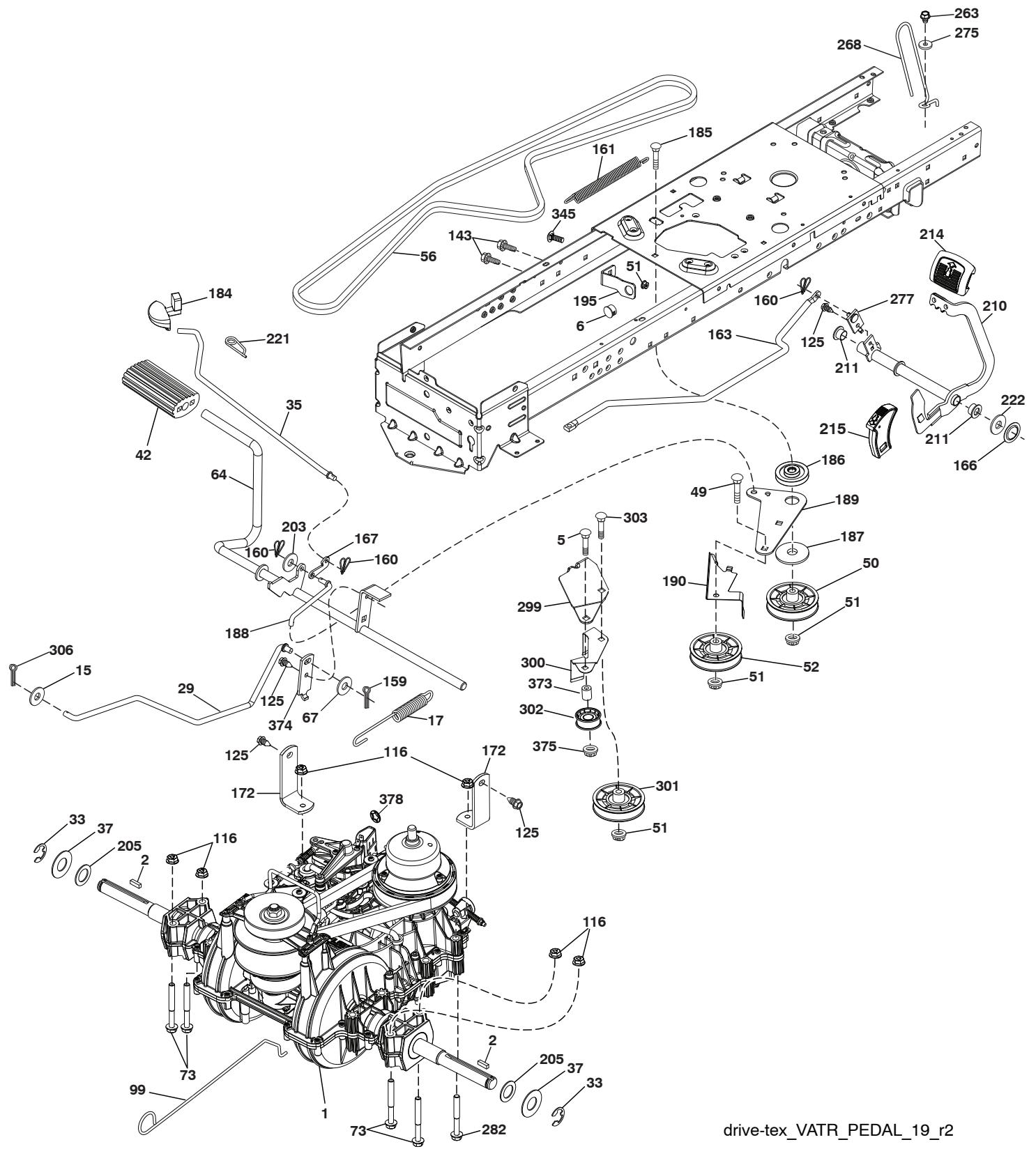
drive-tex_VATR_PEDAL_19_r2
| KEY NO. | PART NO. | DESCRIPTION |
| 1 | -- -- -- -- | Transmission, Gentrans VATR. (580486201) (Order parts from transaxle manufacturer.) |
| 2 | 532 12 35-83 | Key.Square .2.0 x .1845/.1865 |
| 5 | 874 76 06-36 | Bolt Hex |
| 6 | 532 12 40-28 | Bushing Snap |
| 15 | 819 13 13-16 | Washer 13/32 x 13/16 x 16 Ga. |
| 17 | 584 95 40-01 | Spring Brake |
| 29 | 584 82 31-01 | Rod Brake |
| 33 | 812 00 00-01 | E-Ring. #5133-75 |
| 35 | 583 86 45-01 | Rod.Brake.Parking |
| 37 | 532 18 89-67 | Washer Hard .793 x 1.637 x 060 |
| 42 | 532 12 48-72 | Cover.Pedal.Blk.Round |
| 49 | 872 11 06-14 | Bolt.Rdhd.3/8-16Uncx1-3/4.Gr 5 |
| 50 | 532 19 43-27 | Idler Flat |
| 51 | 873 90 06-00 | Nut, Hex, Flangelock 3/8-16 |
| 52 | 532 19 43-26 | Idler.V-Groove-offset |
| 56 | 581 60 38-01 | Belt Drive |
| 64 | 532 44 83-53 | Shaft Asm. Pedal Brake |
| 67 | 819 13 13-12 | Washer 13/32 x 13/16 x 12 Ga. |
| 73 | 874 49 05-44 | Bolt.Hex.Flongleftrightarrow.5/16-18.Gr.5 |
| 99 | 532 43 59-35 | Rod Bypass |
| 116 | 873 90 05-00 | Nut, Lock Hex Flange 5/16-18 unc |
| 125 | 817 00 05-12 | Screw.5/16-18 x 3/4.Smgl.m.Tap/Bl |
| 143 | 817 49 05-08 | Screw.Thdrol.5/16-18 x 1/2 Tytt |
| 159 | 876 02 04-12 | Pin Cotter 1/8 x 3/4 |
| 160 | 532 16 94-84 | Retainer.Clip(M).Dia.290 |
| 161 | 532 10 57-09 | Spring.Return.Clutch.6.75 |
| 163 | 587 84 79-01 | Rod Control Pedal |
| 166 | 532 42 91-64 | Nut Push .625 |
| 167 | 532 40 52-57 | Latch.Brake.Parking |
| 172 | 583 97 42-01 | Strap Torque LH/RH |
| 184 | 587 65 37-01 | Handle.Parking Brake |
| 185 | 872 11 06-22 | Bolt.Rdhd.3/8-16Unc x 2-3/4 Gr.5 |
| 186 | 532 19 43-21 | Spacer.Retainer |
| 187 | 819 13 32-10 | Washer.13/32 x 2 x 10 Ga. |
| KEY NO. | PART NO. | DESCRIPTION |
| 188 | 532 19 43-23 | Link.Clutch.Ground Drive |
| 189 | 532 19 43-17 | Bellcrank.Groundrive.Nstg/Nstl |
| 190 | 532 19 43-18 | Keeper.Bellcrank.Drive.Ground |
| 195 | 581 50 46-01 | Brake Bracket |
| 203 | 819 11 11-16 | Washer 11/32 x 11/16 x 16 |
| 205 | 532 12 17-48 | Washer.25/32 x 1-5/8 x 16 Ga. |
| 210 | 532 44 82-70 | Weldment Pedal |
| 211 | 532 12 01-83 | Bearing Nylon |
| 214 | 532 42 12-63 | Pedal Forward Pad |
| 215 | 532 44 82-54 | Cap Pedal Reverse |
| 221 | 532 40 31-87 | Retainer.Springclip.Handle |
| 222 | 879 21 20-10 | Washer 21/32 x 1-1/4 10 Ga. |
| 263 | 817 00 06-12 | Screw 3/8-16 x 3/4 |
| 268 | 532 18 24-02 | Guard Muffler |
| 275 | 819 13 16-14 | Washer 13/32 x 1 x 14 Ga. |
| 277 | 532 44 85-00 | Link Rocker Pedal |
| 282 | 874 49 05-48 | Screw Thdrol 5/16-18 x 3 |
| 299 | 532 41 56-83 | Bracket Mount Idler |
| 300 | 532 41 56-81 | Keeper Idler Rear |
| 301 | 532 41 56-80 | Pulley Idler V-Groove |
| 302 | 581 42 05-01 | Pulley Idler Flat 2.0 Od |
| 303 | 872 11 06-18 | Bolt Rdhd Sgnk 3/8-16 x 2-1/4 |
| 306 | 876 02 04-16 | Pin Cotter |
| 345 | 872 11 06-06 | Bolt Rdhd Sgnk 3/8-16 x 1 Gr. 5 |
| 373 | 581 46 18-01 | Spacer Idler |
| 374 | 581 47 52-01 | Bracket Brake Arm |
| 375 | 873 68 06-00 | Nut Crownlock |
| 378 | 584 28 77-01 | Nut Push 8 mm |
NOTE: All component dimensions given in U.S. inches 1 inch = 25.4 mm
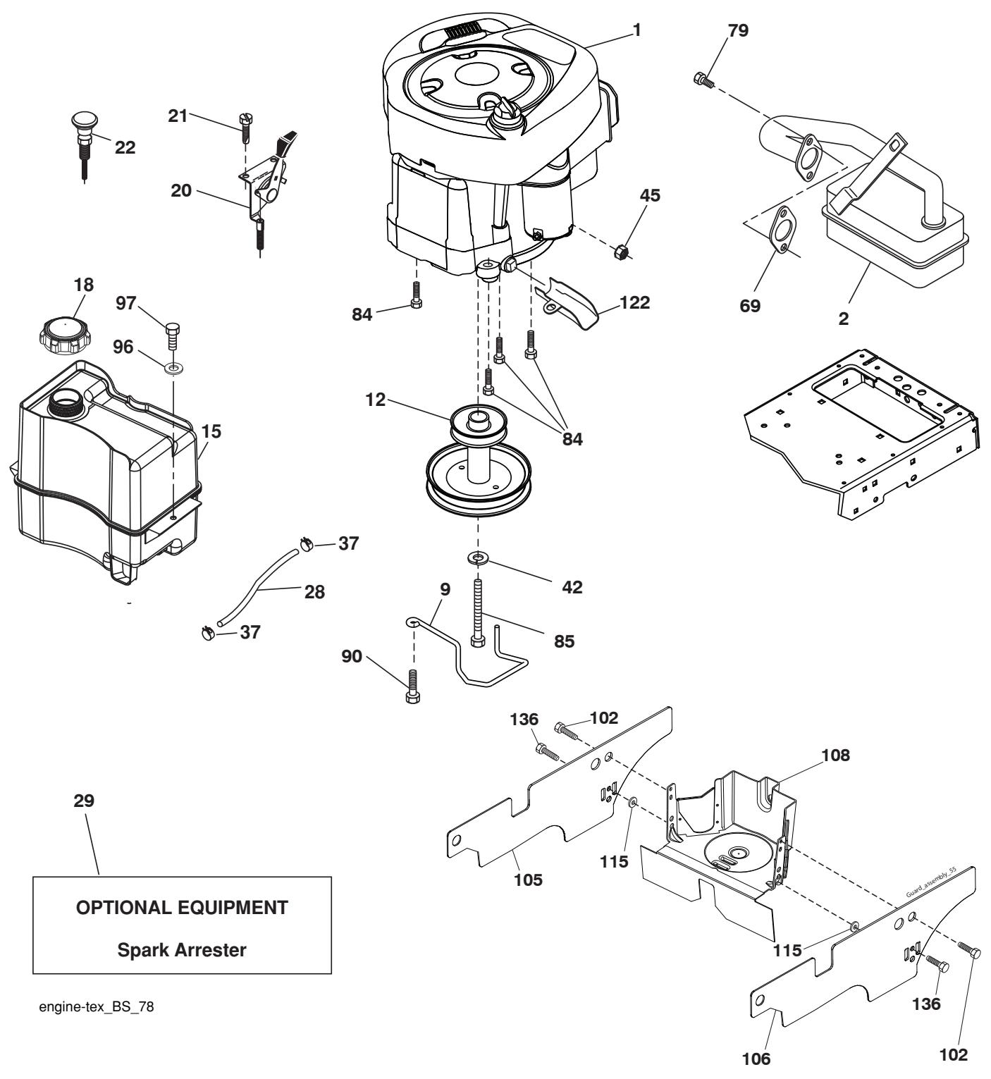
| KEY NO. | PART NO. | DESCRIPTION |
| 1 | -- -- -- -- | Engine Briggs Model No. 31R807-0008-B1 (585688901) (Order parts from engine manufacturer.) |
| 2 | 532 13 73-52 | Muffler |
| 9 | 584 90 80-01 | Keeper Belt Engine |
| 12 | 586 47 85-01 | Pulley Engine |
| 15 | 532 40 75-51 | Tank Fuel |
| 18 | 532 43 02-20 | Cap Asm |
| 20 | 532 18 38-97 | Control Throttle |
| 21 | 532 41 63-58 | Screw #10 x 0.750 BOS Thread |
| 22 | 532 19 49-81 | Control Choke |
| 28 | 532 13 70-40 | Fuel Line |
| 29 | 532 13 71-80 | Spark Arrester Kit |
| 37 | 532 12 34-87 | Clamp Hose |
| 42 | 810 04 07-00 | Washer Lock 7/16 |
| 45 | 873 51 04-00 | Nut Keps Hex 1/4-20 unc |
| 69 | 532 16 52-91 | Gasket |
| 79 | 532 19 23-34 | Screw 5/16-18 x .75 |
| 84 | 817 06 06-20 | Screw 3/8-16 x 1-1/4 |
| 85 | 532 17 39-37 | Bolt 7/16-20 x 4 |
| 90 | 817 00 06-16 | Screw 3/8-16 x 1 |
| 96 | 819 09 14-16 | Washer 9/32 x 7/8 x 16 Ga. |
| 97 | 817 67 04-12 | Screw 1/4 - 20 x 3/4 |
| 102 | 817 00 05-12 | Screw |
| 105 | 532 41 05-28 | Shield Side LH |
| 106 | 532 41 05-29 | Shield Side RH |
| 108 | 532 42 17-94 | Cover Asm. Pulley |
| 115 | 532 42 30-62 | Palnut 1/4 |
| 122 | 532 42 19-22 | Extension Drain Oil |
| 136 | 532 13 77-29 | Screw Thdrol 1/4-20 x 5/8 |
NOTE: All component dimensions given in U.S. inches 1 inch = 25.4 mm
Engine Power Rating Information
The gross power rating for individual gas engine models is labeled in accordance with SAE (Society of Automotive Engineers) code J1940 (Small Engine Power & Torque Rating Procedure), and rating performance has been obtained and corrected in accordance with SAE J1995 (Revision 2002-05). Torque values are derived at 3060 RPM; horsepower values are derived at 3600 RPM. Actual gross engine power will be lower and is affected by, among other things, ambient operating conditions and engine-to-engine variability. Given both the wide array of products on which engines are placed and the variety of environmental issues applicable to operating the equipment, the gas engine will not develop the rated gross power when used in a given piece of power equipment (actual "on-site" or net power). This difference is due to a variety of factors including, but not limited to, accessories (air cleaner, exhaust, charging, cooling, carburetor, fuel pump, etc.), application limitations, ambient operating conditions (temperature, humidity, altitude), and engine-to-engine variability. Due to manufacturing and capacity limitations, Briggs & Stratton may substitute an engine of higher rated power for this Series engine.
TRACTOR -- MODEL NO. M185-107T (96041037801), PRODUCT NO. 960 41 03-78 STEERING ASSEMBLY 41
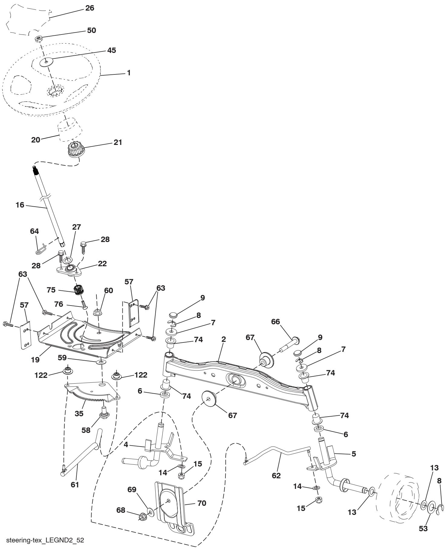
KEY PART
NO. NO.
DESCRIPTION
1 5324428-04
2 5324181-68
4 5324030-87
5 5324030-88
6 5321249-31
7 5321217-48
8 8120000-29
9 5321212-32
13 532 12 17-49
14 8100406-00
15 873 54 06-00
16 5870160-02
19 532 19 47-29
20 5324247-40
21 586 84 02-01
22 5850298-02
26 5324477-59
27 819 21 16-16
28 8170006-12
35 5321947-32
45 5870164-01
50 873 90 06-00
53 5321889-67
57 5324074-65
58 5321947-47
59 5321947-48
60 8739710-00
61 532 19 47-40
62 5321947-41
63 8170005-12
64 532 19 98-49
66 8710207-48
67 5321947-37
68 873 90 07-00
69 5321991-62
70 5853388-01
74 5321249-37
75 5806837-01
76 5806836-01
122 5324449-62
Wheel, Steering
Axle Asm., Front
Spindle Asm., LH
Spindle Asm., RH
Bearing, Race Thrust Harden
Washer 25 / 32 × 1 - 5 / 8 × 16 Ga.
Ring,Clip #T5304-75
Cap, Spindle
Washer 25 / 32 × 1 - 1 / 4 × 16 Ga.
Washer, Lock Hvy Hlcl Spr 3/8
Nut, Crown Lock 3/8-24 unf
Steering Shaft
Plate Steering
Boot Steering
Adapter Wheel Steering
Bearing
Insert, Wheel Steering
Washer
Screw 3/8-16 x 3/4
Gear, Sector Plate
Washer 3/8 ID 2-3/8 OD 12 Ga. PLTD
Nut Lock Flg 3/8-16 unc
Washer Hardened .793 x 1.637 x .060
Bracket Upstop
Bolt Shoulder Sector Pivot CFM
Washer Thrust Sector Steering
Nut Flange Lock 5/8-11
Draglink LH
Draglink, RH
Screw 5/16-18 x 3/4
Retainer Clip Spring Steering
Bolt Hex Fghd 7/16-14 x 3 Serr
Bushing PM Front Axle
Nut Lock Flange 7/16-14 Gr.5
Washer 1.5 x .505 x .118
Bracket Deck Susp. Front
Bearing
Pinion
Screw Head Sock
Cap Gear Sector
NOTE: All component dimensions given in U.S. inches
1 inch = 25.4 mm

| KEY NO. | PART NO. | DESCRIPTION |
| 1 | 532 19 64-95 | Mower Housing |
| 6 | 532 19 51-86 | Arm Suspension |
| 7 | 532 41 63-58 | Screw #10 x 0.750 |
| 11 | 532 13 89-71 | Blade, 42" Hi-Lift (For bagging or discharge) |
| 12 | 584 30 93-01 | Screw Sems 7/16-20 x 1 Hex Head |
| 13 | 587 25 65-01 | Shaft Assembly, Mandrel |
| 14 | 532 18 72-81 | Housing, Mandrel |
| 15 | 585 32 39-01 | Bearing, Mandrel |
| 19 | 532 19 65-39 | Bolt, Shoulder |
| 20 | 532 15 97-70 | Baffle, Vortex |
| 21 | 873 68 05-00 | Nut Crown Lock 5/16-18 |
| 23 | 532 19 25-57 | Bracket, Deflector |
| 24 | 532 10 53-04 | Cap, Sleeve |
| 25 | 532 19 70-26 | Spring, Torsion, Deflector |
| 26 | 532 11 04-52 | Nut, Push |
| 27 | 532 41 14-85 | Shield, Deflector |
| 29 | 532 13 14-91 | Rod, Hinge |
| 32 | 532 19 74-73 | Pulley, Mandrel |
| 33 | 532 40 02-34 | Nut, Toplock, Flanged |
| 34 | 872 11 06-12 | Bolt Carr. Sh. 3/8-16 x 1-1/2 Gr. 5 |
| 35 | 532 13 38-35 | Fastener |
| 36 | 532 19 73-79 | Pulley Idler |
| 37 | 819 13 13-16 | Washer 13/32 x 13/16 x 16 Ga. |
| 38 | 532 43 25-20 | Keeper Belt Mandrel |
| 40 | 873 90 06-00 | Nut, Lock Flg. 3/8-16 unc |
| 41 | 584 95 39-01 | Bolt Hex Wash HD .313-18 x 1.19 |
| 42 | 532 19 84-10 | Spring Trosion Brake |
| 43 | 532 19 72-56 | Spring Torsion Retainer |
| 46 | 532 13 77-29 | Screw Thdrol. 1/4-20 x 5/8 |
| 47 | 532 19 72-50 | Bracket Clutch Cable |
| 55 | 532 43 71-10 | Arm, Idler |
| 56 | 532 19 90-92 | Spacer, Retainer |
| 57 | 817 00 06-16 | Screw Hex Wsh. Thd. 3/8-16 x 1 |
| 59 | 532 14 10-43 | Guard, Tuv. Idler (94) |
| 60 | 532 19 72-61 | Arm Brake Mower |
| 62 | 872 11 06-16 | Bolt Rdhd. Sqnk. 3/8-16 unc x 2 |
| 63 | 532 19 94-77 | Arm Brake Mower |
| 64 | 532 19 97-90 | Linkage Brake |
| 67 | 532 40 30-12 | Handle, Clutch Cable |
| KEY NO. | PART NO. | DESCRIPTION |
| 68 | 532 42 96-36 | V-Belt |
| 69 | 872 14 05-05 | Bolt Rdhd. Sqnk. 5/16-18 x 5/8 |
| 70 | 532 19 99-72 | Clutch Asm. Manual |
| 80 | 532 42 30-62 | Palnut 1/4 |
| 113 | 817 00 05-10 | Screw 5/16-18 |
| 116 | 532 12 48-42 | Bolt, Shoulder |
| 117 | 532 18 86-06 | Wheel, Gauge |
| 122 | 532 19 72-58 | Keeper Belt Eng. LH |
| 123 | 532 19 72-59 | Keeper Belt Eng. RH |
| 144 | 532 19 92-04 | Keeper Belt |
| 145 | 532 19 31-97 | Pulley, Idler, Flat |
| 147 | 532 40 19-71 | Spring Return |
| 152 | 584 24 35-01 | Cable Mechanical Clutch |
| 188 | 532 19 51-61 | Stud Fastener |
| 189 | 873 90 05-00 | Nut Lock Hex Flange |
| 192 | 532 19 72-60 | Bracket Brake Stand LH |
| 195 | 817 00 06-12 | Screw Hex Wsh. Thdrol. 3/8-16 x 3/4 |
| 196 | 819 12 14-14 | Washer 13/32 x 7/8 x 14 Ga. |
| 241 | 532 15 29-27 | Screw |
| 242 | 532 41 55-98 | Port Washout |
| 243 | 532 43 23-94 | Cover Deck 42" |
| 247 | 532 43 02-61 | Shield Deck RH |
| 248 | 532 43 02-60 | Shield Deck LH |
| 249 | 532 40 65-14 | Cover Cable Clutch |
| 253 | 532 42 73-50 | Rivot Tuflock |
| 280 | 817 67 06-08 | Screw Thdrol 3/8-16 x 1/2 |
| -- | 587 25 33-01 | Mandrel Assembly (Includes housing (key #14), shaft assembly (key #13) and bearing only (key #15) - Pulley/Nut/Washer and Blade Bolt/Washers not included) |
| -- | 532 43 77-30 | Replacement Mower, Complete |
NOTE: All component dimensions given in U.S. inches 1 inch = 25.4 mm
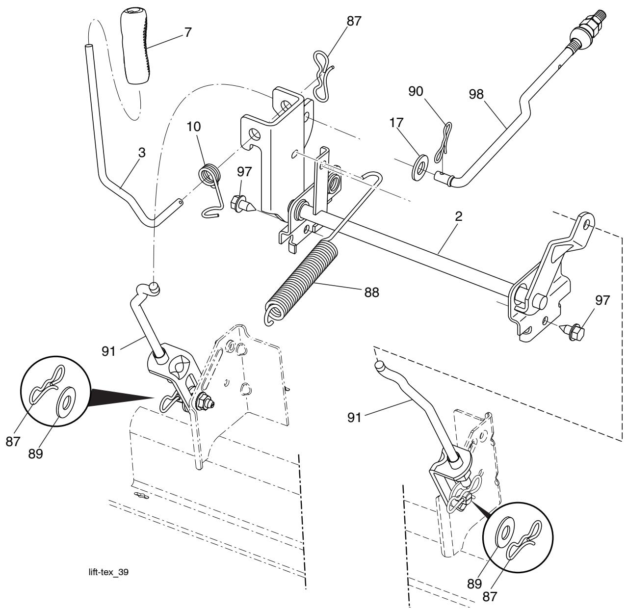
KEY PART
NO. NO.
2 5324220-27
3 5321952-31
7 5809623-01
10 532 19 63-14
17 819 13 13-12
87 5321942-09
88 5324107-10
89 819 19 19-12
DESCRIPTION
Shaft Asm., Lift
Lever Asm., Lift RH
Grip, Lever
Spring Torsion
Washer 13/32 x 13/16 x 12 Ga.
Pin Cotter 7/16 Bow Tie Lock
Spring Lift Assist
Washer 17/32 x 1-3/16 x 12 Ga.
KEY PART
NO. NO.
90 5321942-08
91 532 19 79-84
97 8170006-12
98 5324205-25
DESCRIPTION
Pin Cotter 5/16 Bow Tie Lock
Link Lift Susp Mower Rear
Screw 3/8-16 x .75
Link Lift Susp. Front Mower
NOTE: All component dimensions given in U.S. inches 1 inch = 25.4 mm
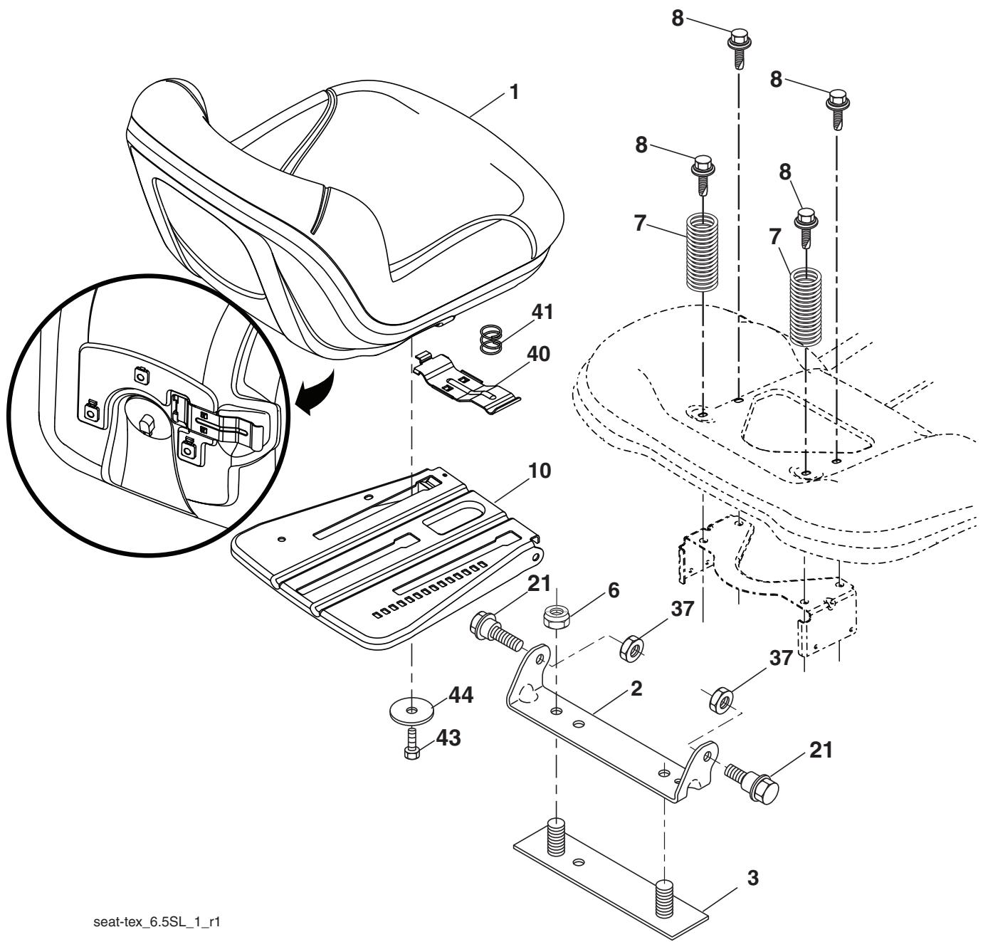
KEY PART
NO. NO.
DESCRIPTION
1 5814622-01 S
2 5321801-66 B
3 5321406-75 S
6 873 80 06-00 N
7 5876133-01
8 5321718-77 B
10 532 19 69-77
21 532 17 18-52
Seat
Bracket Pivot Fender
Strap, Asm Fender
Nut, Lock w/Ins. 3/8-16 unc
Spring, Seat Cprsn
Bolt 5/16-18 unc x 3/4 w/Sems
Pan, Seat
Bolt, Shoulder 5/16-18
KEY PART
NO. NO.
DESCRIPTION
37 873 80 05-00
40 5321976-61
41 532 19 82-00
43 874 76 06-12
44 819 13 38-12
Nut, Lock 5/16-18 unc
Handle Slide Seat
Spring Latch Seat
Bolt 3/8-16 x 3/4
Washer 13 / 32 × 2 - 3 / 8 × 12 Ga.
NOTE: All component dimensions given in U.S. inches 1 inch = 25.4 mm