
4351FCT - Scie sauteuse MAKITA - Notice d'utilisation et mode d'emploi gratuit
Retrouvez gratuitement la notice de l'appareil 4351FCT MAKITA au format PDF.

| Type de produit | Scie sauteuse |
| Marque | Makita |
| Modèle | 4351FCT |
| Longueur de course | 26 mm |
| Capacités de coupe maximum | Bois : 135 mm, Acier : 10 mm, Aluminium : 20 mm |
| Courses par minute | 800 - 2 800 min⁻¹ (réglable) |
| Longueur totale | 271 mm |
| Poids net | 2,5 kg |
| Alimentation | Monophasé CA, tension nominale (voir plaque signalétique) |
| Classe de sécurité | Double isolation (Classe II) |
| Vitesse variable | Oui, molette de réglage de 1 à 5 |
| Action orbitale | 4 positions (0, I, II, III) |
| Lumière LED | Oui, s'allume en actionnant la gâchette |
| Démarrage progressif | Oui |
| Maintien constant de la vitesse | Oui, sous charge |
| Coupe en biseau | 0° à 45° à gauche et à droite |
| Coupe de plongée | Possible |
| Extraction de poussière | Buse de poussière en option, compatible aspirateur Makita |
| Guide parallèle | En option (guide de refend) |
| Guide de cercle | En option (guide de refend avec goujon circulaire) |
| Plaque de protection | En option pour surfaces délicates |
| Dispositif anti-éclats | En option |
| Niveau sonore | Pression acoustique LpA = 85 dB(A), incertitude K = 3 dB(A) |
| Vibration (coupe panneau de particules) | ah = 6,5 m/s², incertitude K = 1,5 m/s² |
| Vibration (coupe tôle) | ah = 4,5 m/s², incertitude K = 1,5 m/s² |
FOIRE AUX QUESTIONS - 4351FCT MAKITA
Questions des utilisateurs sur 4351FCT MAKITA
0 question sur cet appareil. Repondez a celles que vous connaissez ou posez la votre.
Poser une nouvelle question sur cet appareil
Téléchargez la notice de votre Scie sauteuse au format PDF gratuitement ! Retrouvez votre notice 4351FCT - MAKITA et reprennez votre appareil électronique en main. Sur cette page sont publiés tous les documents nécessaires à l'utilisation de votre appareil 4351FCT de la marque MAKITA.
MODE D'EMPLOI 4351FCT MAKITA
INSTRUCTION MANUAL
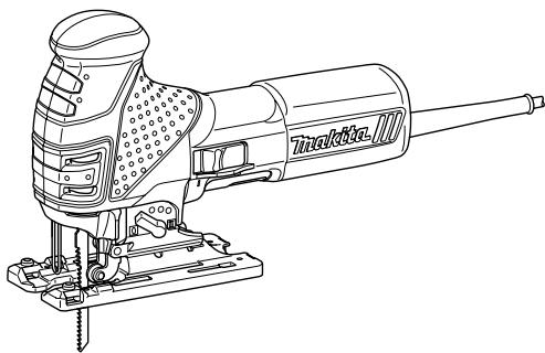
Jig Saw
4351T
4351CT
4351FCT
008029

DOUBLE INSULATION
ENGLISH SPECIFICATIONS
| Model | 4351T | 4351CT | 4351FCT | |
| Length of stroke | 26 mm | 26 mm | 26 mm | |
| Max. cutting capacities | Wood | 135 mm | 135 mm | 135 mm |
| Steel | 10 mm | 10 mm | 10 mm | |
| Aluminum | 20 mm | 20 mm | 20 mm | |
| Strokes per minute (min-1) | 2,800 | 800 - 2,800 | 800 - 2,800 | |
| Overall length | 271 mm | 271 mm | 271 mm | |
| Net weight | 2.4 kg | 2.5 kg | 2.5 kg | |
| Safety class | ☐/II | |||
- Due to our continuing programme of research and development, the specifications herein are subject to change without notice.
- Note: Specifications may differ from country to country.
END201-2
Symbols
The following show the symbols used for the equipment. Be sure that you understand their meaning before use.

- Read instruction manual.

DOUBLE INSULATION

Only for EU countries
Do not dispose of electric equipment together with household waste material! In observance of European Directive 2002/96/EC on waste electric and electronic equipment and its implementation in accordance with national law, electric equipment that have reached the end of their life must be collected separately and returned to an environmentally compatible recycling facility.
ENE019-1
Intended use
The tool is intended for the sawing of wood, plastic and metal materials. As a result of the extensive accessory and saw blade program, the tool can be used for many purposes and is very well suited for curved or circular cuts.
ENF002-1
Power supply
The tool should be connected only to a power supply of the same voltage as indicated on the nameplate, and can only be operated on single-phase AC supply. They are double-insulated in accordance with European Standard and can, therefore, also be used from sockets without earth wire.
For Model 4351T
ENG101-1
For European countries only Noise
The typical A-weighted noise level determined according to EN60745-2-11:
Sound pressure level (L_PA):85dB(A)
Uncertainty (K) : 3 dB(A)
The noise level under working may exceed 85 dB (A).
Wear ear protection.
ENG220-1
Vibration
The vibration total value (tri-axial vector sum) determined according to EN60745-2-11:
Work mode : cutting chipboard
Vibration emission (a_h,CW):7m / s^2
Uncertainty (K): 1.5m/s^2
ENG304-1
Work mode : cutting sheet metal
Vibration emission (a_h,CM):4.5m / s^2
Uncertainty (K): 1.5m / s^2
For Model 4351CT, 4351FCT
ENG101-1
For European countries only Noise
The typical A-weighted noise level determined according to EN60745-2-11:
Sound pressure level (L_pa):85dB(A)
Uncertainty (K) : 3 dB(A)
The noise level under working may exceed 85 dB (A).
Wear ear protection.
ENG220-1
Vibration
The vibration total value (tri-axial vector sum) determined according to EN60745-2-11:
Work mode : cutting chipboard
Vibration emission (a_h,CW):6.5m / s^2
Uncertainty (K) : 1.5 m/s²
ENG304-1
Work mode: cutting sheet metal
Vibration emission (a_h,CM): 4.5 m/s^2 Uncertainty (K): 1.5 m/s^2
ENH101-7
EC-DECLARATION OF CONFORMITY
Model; 4351T, 4351CT, 4351FCT
We declare under our sole responsibility that this product is in compliance with the following standards of standardized documents;
EN60745, EN55014, EN61000 in accordance with Council Directives, 2004/108/EC, 98/37/EC.
CE2006

000230
Tomoyasu Kato Director
Responsible Manufacturer:
Makita Corporation
3-11-8, Sumiyoshi-cho, Anjo, Aichi, JAPAN
Authorized Representative in Europe:
Makita International Europe Ltd.
Michigan Drive, Tongwell, Milton Keynes, Bucks MK15 8JD, ENGLAND
GEA001-3
General Safety Rules
WARNING! Read all instructions. Failure to follow all instructions listed below may result in electric shock, fire and/or serious injury. The term "power tool" in all of the warnings listed below refers to your mains-operated (corded) power tool or battery-operated (cordless) power tool.
SAVE THESE INSTRUCTIONS.
Work area safety
- Keep work area clean and well lit. Cluttered and dark areas invite accidents.
- Do not operate power tools in explosive atmospheres, such as in the presence of flammable liquids, gases or dust. Power tools create sparks which may ignite the dust or fumes.
- Keep children and bystanders away while operating a power tool. Distractions can cause you to lose control.
Electrical safety
- Power tool plugs must match the outlet. Never modify the plug in any way. Do not use any adapter plugs with earthed (grounded) power tools. Unmodified plugs and matching outlets will reduce risk of electric shock.
- Avoid body contact with earthed or grounded surfaces such as pipes, radiators, ranges and refrigerators. There is an increased risk of
electric shock if your body is earthed or grounded.
6. Do not expose power tools to rain or wet conditions. Water entering a power tool will increase the risk of electric shock.
7. Do not abuse the cord. Never use the cord for carrying, pulling or unplugging the power tool. Keep cord away from heat, oil, sharp edges or moving parts. Damaged or entangled cords increase the risk of electric shock.
8. When operating a power tool outdoors, use an extension cord suitable for outdoor use. Use of a cord suitable for outdoor use reduces the risk of electric shock.
Personal safety
- Stay alert, watch what you are doing and use common sense when operating a power tool. Do not use a power tool while you are tired or under the influence of drugs, alcohol or medication. A moment of inattention while operating power tools may result in serious personal injury.
- Use safety equipment. Always wear eye protection. Safety equipment such as dust mask, non-skid safety shoes, hard hat, or hearing protection used for appropriate conditions will reduce personal injuries.
- Avoid accidental starting. Ensure the switch is in the off-position before plugging in. Carrying power tools with your finger on the switch or plugging in power tools that have the switch on invites accidents.
- Remove any adjusting key or wrench before turning the power tool on. A wrench or a key left attached to a rotating part of the power tool may result in personal injury.
- Do not overreach. Keep proper footing and balance at all times. This enables better control of the power tool in unexpected situations.
- Dress properly. Do not wear loose clothing or jewellery. Keep your hair, clothing, and gloves away from moving parts. Loose clothes, jewellery or long hair can be caught in moving parts.
- If devices are provided for the connection of dust extraction and collection facilities, ensure these are connected and properly used. Use of these devices can reduce dust-related hazards.
Power tool use and care
- Do not force the power tool. Use the correct power tool for your application. The correct power tool will do the job better and safer at the rate for which it was designed.
- Do not use the power tool if the switch does not turn it on and off. Any power tool that cannot
be controlled with the switch is dangerous and must be repaired.
- Disconnect the plug from the power source and/or the battery pack from the power tool before making any adjustments, changing accessories, or storing power tools. Such preventive safety measures reduce the risk of starting the power tool accidentally.
- Store idle power tools out of the reach of children and do not allow persons unfamiliar with the power tool or these instructions to operate the power tool. Power tools are dangerous in the hands of untrained users.
- Maintain power tools. Check for misalignment or binding of moving parts, breakage of parts and any other condition that may affect the power tools operation. If damaged, have the power tool repaired before use. Many accidents are caused by poorly maintained power tools.
- Keep cutting tools sharp and clean. Properly maintained cutting tools with sharp cutting edges are less likely to bind and are easier to control.
- Use the power tool, accessories and tool bits etc. in accordance with these instructions and in the manner intended for the particular type of power tool, taking into account the working conditions and the work to be performed. Use of the power tool for operations different from those intended could result in a hazardous situation.
Service
- Have your power tool serviced by a qualified repair person using only identical replacement parts. This will ensure that the safety of the power tool is maintained.
- Follow instruction for lubricating and changing accessories.
- Keep handles dry, clean and free from oil and grease.
GEB016-1
SPECIFIC SAFETY RULES
DO NOT let comfort or familiarity with product (gained from repeated use) replace strict adherence to jig saw safety rules. If you use this tool unsafely or incorrectly, you can suffer serious personal injury.
- Hold power tools by insulated gripping surfaces when performing an operation where the cutting tool may contact hidden wiring or its own cord. Contact with a "live" wire will make exposed metal parts of the tool "live" and shock the operator.
- Use clamps or another practical way to secure and support the workpiece to a stable platform.
Holding the work by hand or against your body leaves it unstable and may lead to loss of control.
- Always use safety glasses or goggles. Ordinary eye or sun glasses are NOT safety glasses.
- Avoid cutting nails. Inspect workpiece for any nails and remove them before operation.
- Do not cut oversize workpiece.
- Check for the proper clearance beyond the workpiece before cutting so that the blade will not strike the floor, workbench, etc.
- Hold the tool firmly.
- Make sure the blade is not contacting the workpiece before the switch is turned on.
- Keep hands away from moving parts.
- Do not leave the tool running. Operate the tool only when hand-held.
- Always switch off and wait for the blade to come to a complete stop before removing the blade from the workpiece.
- Do not touch the blade or the workpiece immediately after operation; they may be extremely hot and could burn your skin.
- Do not operate the tool at no-load unnecessarily.
- Some material contains chemicals which may be toxic. Take caution to prevent dust inhalation and skin contact. Follow material supplier safety data.
- Always use the correct dust mask/respirator for the material and application you are working with.
SAVE THESE INSTRUCTIONS.
WARNING:
MISUSE or failure to follow the safety rules stated in this instruction manual may cause serious personal injury.
FUNCTIONAL DESCRIPTION
CAUTION:
Always be sure that the tool is switched off and unplugged before adjusting or checking function on the tool.
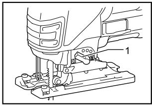
Selecting the cutting action
008030
- Cutting action changing lever
This tool can be operated with an orbital or a straight line (up and down) cutting action. The orbital cutting action thrusts the blade forward on the cutting stroke and greatly increases cutting speed.
To change the cutting action, just turn the cutting action changing lever to the desired cutting action position. Refer to the table to select the appropriate cutting action.
| Position | Cutting action | Applications |
| 0 | Straight line cutting action | For cutting mild steel, stainless steel and plastics. For clean cuts in wood and plywood. |
| I | Small orbit cutting action | For cutting mild steel, aluminum and hard wood. |
| II | Medium orbit cutting action | For cutting wood and plywood. For fast cutting in aluminum and mild steel. |
| III | Large orbit cutting action | For fast cutting in wood and plywood. |
006376
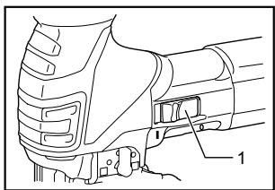
Switch action
1. Switch lever
008031
CAUTION:
Before plugging in the tool, always be sure that the tool is switched off.
To start the tool, slide the switch lever to the "I" position.
To stop the tool, slide the switch lever to the "O" position.
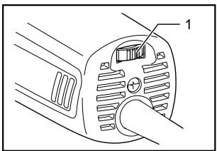
Speed adjusting dial For 4351CT, 4351FCT
006368
- Speed adjusting dial
008032
The tool speed can be infinitely adjusted between 800 and 2,800 strokes per minute by turning the adjusting dial. Higher speed is obtained when the dial is turned in the direction of number 5; lower speed is obtained when it is turned in the direction of number 1.
Refer to the table to select the proper speed for the workpiece to be cut. However, the appropriate speed may differ with the type or thickness of the workpiece. In general, higher speeds will allow you to cut workpieces faster but the service life of the blade will be reduced.
| Workpiece to be cut | Number on adjusting dial |
| Wood | 4 - 5 |
| Mild steel | 3 - 5 |
| Stainless steel | 3 - 4 |
| Aluminum | 3 - 5 |
| Plastics | 1 - 4 |
CAUTION:
The speed adjusting dial can be turned only as far as 5 and back to 1. Do not force it past 5 or 1, or the speed adjusting function may no longer work.
The tools equipped with electronic function are easy to operate because of the following features.
Constant speed control
Electronic speed control for obtaining constant speed. Possible to get fine finish, because the rotating speed is kept constant even under load condition.
Soft start feature
Safety and soft start because of suppressed starting shock.
Lighting up the lamps
For 4351FCT only
CAUTION:
- Do not look in the light or see the source of light directly.
To turn on the lamp, pull the trigger. Release the trigger to turn it off.
NOTE:
Use a dry cloth to wipe the dirt off the lens of lamp. Be careful not to scratch the lens of lamp, or it may lower the illumination.
ASSEMBLY
CAUTION:
Always be sure that the tool is switched off and unplugged before carrying out any work on the tool.
Installing or removing saw blade
CAUTION:
Always clean out all chips or foreign matter adhering to the blade and/or blade holder. Failure to do so may cause insufficient tightening of the blade, resulting in a serious personal injury.
- Do not touch the blade or the workpiece immediately after operation; they may be extremely hot and could burn your skin.
- Tighten the saw blade securely. Failure to do so may cause a serious injury.
- When you remove the saw blade, be careful not to hurt your fingers with the top of the blade or the tips of workpiece.
To install the blade, open the tool opener to the position shown in the figure.
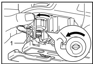
1. Tool opener
008007
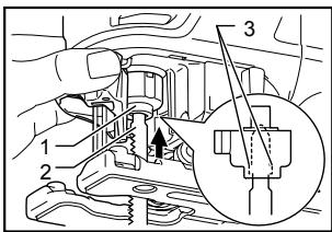
Keeping that situation, insert the saw blade into the blade clamp as far as the two protrusions of the blade can not be seen.
008008
- Blade clamp
- Jig saw blade
- Protrusions
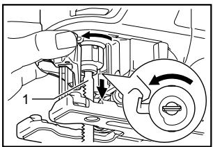
Return the tool opener to its original position.
After installing, always make sure that the blade is securely held in place by trying to pull it out.
CAUTION:
- Do not open the tool opener excessively, or it may cause tool damage.
To remove the blade, open the tool opener to the position shown in the figure. Pull the saw blade out toward the base.
008009
- Jig saw blade
NOTE:
Occasionally lubricate the roller.
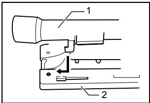
Hex wrench storage
008033
- Base
- Hex wrench
When not in use, the hex wrench can be conveniently stored.
OPERATION
CAUTION:
- Hold the tool firmly with one hand on the switch handle and the other hand on the front grip when performing the tool.
Always hold the base flush with the workpiece. Failure to do so may cause blade breakage, resulting in a serious injury.
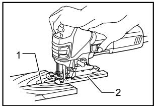
- Cutting line
- Base
008034
Turn the tool on and wait until the blade attains full speed. Then rest the tool base flat on the workpiece and gently move the tool forward along the previously marked cutting line. When cutting curves, advance the tool very slowly.
Bevel cutting
008035
CAUTION:
Always be sure that the tool is switched off and unplugged before tilting the base.
With the base tilted, you can make bevel cuts at any angle between 0^ and 45^ (left or right).
Loosen the bolt on the back of the base with the hex wrench. Move the base so that the bolt is positioned in the center of the bevel slot in the base.
- Base
- Bolt
- Hex wrench
Tilt the base until the desired bevel angle is obtained. The V-notch of the gear housing indicates the bevel angle by graduations. Then tighten the bolt firmly to secure the base.
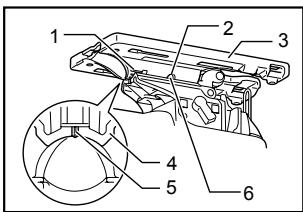
008014
- Graduation
- Bevel slot
- Base
- Gear housing
- V-notch
- Bolt
Front flush cuts
008015
- Base
- Bolt
- Hex wrench
Loosen the bolt on the back of the base with the hex wrench and slide the base all the way back. Then tighten the bolt to secure the base.
Cutouts
Cutouts can be made with either of two methods A or B.
A) Boring a starting hole:
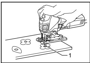
- Starting hole
008036
For internal cutouts without a lead-in cut from an edge, pre-drill a starting hole 12mm or more in diameter. Insert the blade into this hole to start your cut.
008013
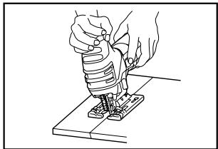
B) Plunge cutting:
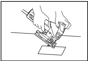
008037
You need not bore a starting hole or make a lead-in cut if you carefully do as follows.
(1) Tilt the tool up on the front edge of the base with the blade point positioned just above the workpiece surface.
(2) Apply pressure to the tool so that the front edge of the base will not move when you switch on the tool and gently lower the back end of the tool slowly.
(3) As the blade pierces the workpiece, slowly lower the base of the tool down onto the workpiece surface.
(4) Complete the cut in the normal manner.
Finishing edges

008038
To trim edges or make dimensional adjustments, run the blade lightly along the cut edges.
Metal cutting
Always use a suitable coolant (cutting oil) when cutting metal. Failure to do so will cause significant blade wear. The underside of the workpiece can be greased instead of using a coolant.
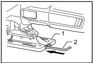
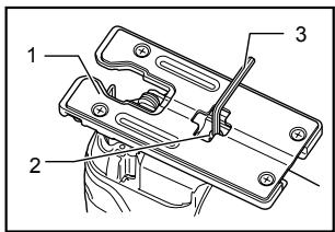
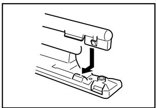
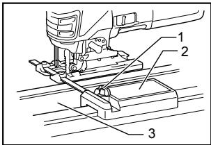
Dust extraction
1. Dust nozzle
2. Base
001922
The dust nozzle (accessory) is recommended to perform clean cutting operations.
To attach the dust nozzle on the tool, insert the hook of dust nozzle into the hole in the base.
The dust nozzle can be installed on either left or right side of the base.
Then connect a Makita vacuum cleaner to the dust nozzle.
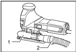
008039
1. Dust nozzle
2. Hose for vacuum cleaner
CAUTION:
If you try to remove the dust nozzle forcibly, the hook of the dust nozzle can be diminished and removed unintentionally during operation.
Rip fence set (optional accessory)
CAUTION:
Always be sure that the tool is switched off and unplugged before installing or removing accessories.
1. Straight cuts
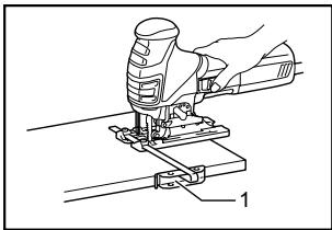
1. Rip fence
008040
001921
008041
- Hex wrench
- Bolt
- Fence guide
When repeatedly cutting widths of 160~mm or less, use of the rip fence will assure fast, clean, straight cuts. To install, insert the rip fence into the rectangular hole on the side of the tool base with the fence guide facing down. Slide the rip fence to the desired cutting width position, then tighten the bolt to secure it.
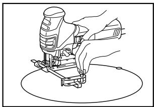
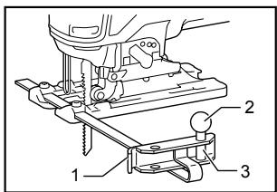
2. Circular cuts
008042
- Fence guide
- Threaded knob
- Circular guide pin
008043
When cutting circles or arcs of 170mm or less in radius, install the rip fence as follows.
Insert the rip fence into the rectangular hole on the side of the base with the fence guide facing up. Insert the circular guide pin through either of the two holes on the fence guide. Screw the threaded knob onto the pin to secure the pin.
Now slide the rip fence to the desired cutting radius, and tighten the bolt to secure it in place. Then move the base all the way forward.
NOTE:
Always use blades No. B-17, B-18, B-26 or B-27 when cutting circles or arcs.
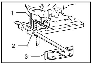
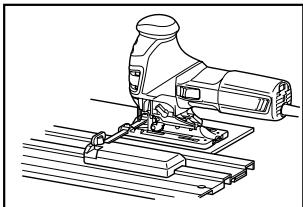
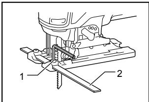
Guide rail adapter set (accessory)
008044
When cutting parallel and uniform width or cutting straight, the use of the guide rail and the guide rail adapter will assure the production of fast and clean cuts. To install the guide rail adapter, insert the rule bar into the square hole of the base as far as it goes. Secure the bolt with the hex wrench securely.
008045
- Bolt
- Rule bar
Install the guide rail adapter on the rail of the guide rail. Insert the rule bar into the square hole of the guide rail adapter. Put the base to the side of the guide rail, and secure the bolt securely.
008046
- Screw
- Guide rail adapter
- Guide rail
CAUTION:
Always use blades No. B-8, B-13, B-16, B-17 or 58 when using the guide rail and the guide rail adapter.
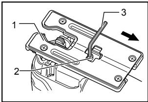
Cover plate
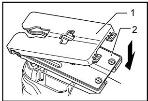
008027
- Cover plate
- Base
Use the cover plate when cutting decorative veneers, plastics, etc. It protects sensitive or delicate surfaces from damage. Fit it on the back of the tool base.
Anti-splintering device
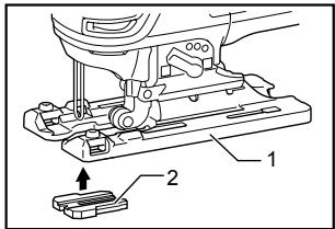
008028
- Base
- Anti-splintering device
For splinter-free cuts, the anti-splintering device can be used. To install the anti-splintering device, move the tool base all the way forward and fit it from the back of tool base. When you use the cover plate, install the anti-splintering device onto the cover plate.
CAUTION:
- The anti-splintering device cannot be used when making bevel cuts.
MAINTENANCE
CAUTION:
Always be sure that the tool is switched off and unplugged before attempting to perform inspection or maintenance.
To maintain product SAFETY and RELIABILITY, repairs, carbon brush inspection and replacement, any other maintenance or adjustment should be performed by Makita Authorized Service Centers, always using Makita replacement parts.
ACCESSORIES
CAUTION:
These accessories or attachments are recommended for use with your Makita tool specified in this manual. The use of any other accessories or attachments might present a risk of injury to persons. Only use accessory or attachment for its stated purpose.
If you need any assistance for more details regarding these accessories, ask your local Makita Service Center.
Jig saw blades
Hex wrench 4
Rip fence (guide rule) set
Guide rail adapter set
Guide rail set
- Anti-splintering device
Dust nozzle
Cover plate
- Hose (For vacuum cleaner)
Makita Corporation Anjo, Aichi, Japan