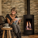
ORSANNE - Cheminée insert WANDERS - Notice d'utilisation et mode d'emploi gratuit
Retrouvez gratuitement la notice de l'appareil ORSANNE WANDERS au format PDF.




| Type de produit | Cheminée insert à gaz |
| Marque | WANDERS |
| Modèle | ORSANNE (également désigné BORDEAUX) |
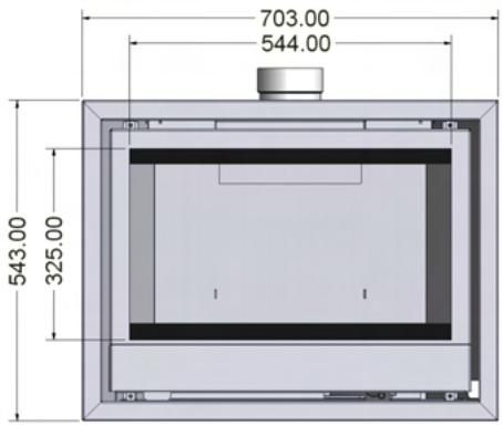
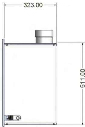
| Dimensions (H x L x P) | 511 x 660 x 323 mm |
| Poids approximatif | 40 kg |
| Alimentation en gaz | Gaz naturel (G20) ou propane (G25) selon le pays |
| Pression d'alimentation (gaz naturel) | 20 mbar en amont, 16 mbar en fonctionnement |
| Puissance nominale | 4,3 kW (max) |
| Rendement | 81% (net) |
| Consommation maximale (gaz naturel) | 0,445 m³/h |
| Diamètre de raccordement fumée | 100 mm minimum |
| Allumage | Piézo électrique avec veilleuse |
| Commande | Télécommande avec récepteur intégré |
| Fonctions de la télécommande | Réglage continu de la flamme, mode automatique, programmateur hebdomadaire, affichage température |
| Piles requises | Télécommande : 1 x 9V alcaline ; récepteur : 4 x AA 1,5V |
| Sécurité | Thermocouple de veilleuse, thermique de retour de fumées (TTB), arrêt automatique après 2h sans signal |
| Matériau de la vitre | Verre céramique résistant à la chaleur |
| Jeu de bûches | Bûches en céramique fournies, disposition spécifique selon le type de gaz |
| Entretien annuel recommandé | Nettoyage du brûleur, veilleuse, chambre de combustion et conduit de fumée par un professionnel |
| Nettoyage de la vitre | Utiliser un produit spécial pour vitres céramiques |
| Garantie constructeur | 2 ans (hors consommables et verre) |
| Notice disponible en | Français, Anglais, Néerlandais, Allemand, etc. |
FOIRE AUX QUESTIONS - ORSANNE WANDERS
Questions des utilisateurs sur ORSANNE WANDERS
0 question sur cet appareil. Repondez a celles que vous connaissez ou posez la votre.
Poser une nouvelle question sur cet appareil
Téléchargez la notice de votre Cheminée insert au format PDF gratuitement ! Retrouvez votre notice ORSANNE - WANDERS et reprennez votre appareil électronique en main. Sur cette page sont publiés tous les documents nécessaires à l'utilisation de votre appareil ORSANNE de la marque WANDERS.
MODE D'EMPLOI ORSANNE WANDERS
INSTALLATIE EN BEDIENINGSVOORSCHRIFTEN VOOR:
INSTALLATION AND OPERATION INSTRUCTIONS FOR:
BORDEAUX
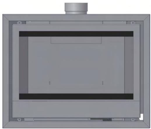
WANDERS
www.wanders.com
NL GB
INHOUDSOPGAVE
1.0 TECHNISCHE AANWIJZINGEN VOOR INSTALLATEUR
2.0 INSTALLATIE VOORSCHRIFTEN
2.1 TECHNISCHE AANWIJZINGEN
2.1.1 SCHOORSTEEN
2.2 INSTALLEREN VAN DE KACHEL
2.3 AANSLUITEN VAN DE SCHOORSTEEN
2.4 AANSLUITING VAN DE GASLEIDING
2.5 ONDERHOUD
2.6 TTB
2.7 HOUTSET
2.8 AFSTANDBEDIENING
2.9 GEBRUIKS AANWIJZING AFSTANDSBEDIENING
3.0 GEBRUIKERS HANDLEIDING
3.1 INGEBRUIK STELLEN VAN DE KACHEL
3.2 BUITEN WERKING STELLEN VAN DE HOOFDBRANDER
3.3 BUITEN WERKING STELLEN VAN DE WAAKVLM
3.4 VOORSCHRIFTEN VOOR DE GEBRUIKER
3.5 TTB BEVEILIGING
3.6 EERSTE KEER STOKEN
3.7 ONDERHOUD
3.8 VENTILATIE
3.9 WAARSCHUWING/ADVIES
MANUAL GB PAGE 17
1. TECHNISCHE AANWIJZINGEN VOOR INSTALLATEUR
Belangrijk
Voordat u de gashaard plaatst en in gebruik neemt, is het zaak deze instructecties zorgvuldig te lezen. Bewaar ze!!! Bij de constructie van once kachels hebben wij nicht alleen de groostte aandacht besteen aanuitvoerng en uiterlijk, maar ook eenemaxle gebruiksviendelijkheid en bedrijfszerkerheid.
Wij hebben er dan ook het volste vertrouwen in dat u jarenlang plezier zult hebben van de door u gekozen gaskachel.
2. INSTALLATIE VOORSCHRIFTEN
2.1 Technische aanwijzingen.
- Controller of de kachel voor de juiste gassoort geleverd is (dit is aan geveen op het typeplaatje)
- Controller of de gasdruk juist is (dit is aangegeven op het typeplaatje)
- De verbrandingslucht wordenuit de ruimte gehaald zorg daemon voor voldoende ventilatie.
- Deze haard mag nooit geplaatst worden in mechanisch geventileerde woningen
- De verbrandingsgassen dieren door een waarvoor geschikt afvoer kanaal afgevoerd te worden
- De kachel dient geplaatst aangesloten en gecontroleerd te worden door een erkend gas technisch installateur.
- Instelwaarden veranderen en overige aanpassingen mogen alleen gebeuren door een erkend installateur en alleen volgens de voorschriften.
- Het toestel dient geplaatst te worden in een onbrandbare nis.
- Indien u gebruikt maakt van een bestand rookkanaal plaatst u minimaal 1 meter roestvast stalen buis van rond 100mm op de kachel.
- Laat uw schoorsteen kanaal te allen tijde voor plaatsing van de gashaard vakkundig reinigen.
- Houd u aan de geldende algemene gasinstallatie voerschriften.
- Inbouwmaten hoogte 511 breedte 660 diepte 323
- Bij het inbouwen van het toestel dient er onceveer 2 cm ruimteussen de inbouwkast en de schouw te zitten.
- Het toestel dient volgens de geldende lokale en regionale voorschriften geplaatst te worden.
2.1.1 Schoorsteen.
Wanneer aan de schoorsteen een kolen of oliekachel heeft gebrand LAST het schoorsteen kanaal dan eerst vakkundig reinigen hoewel een gaskachel kan werken met een geringe schoorsteen trek adviseren wij een Jaarlijke contro ne van de schoorsteen op eventuele verstoppen genz.
2.2 Installeren van de kachel.
Verwijder de verpakking.
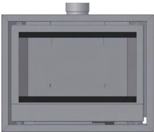
1 Verwijder de twee schroeven anschter de bedieningsdeur (zie fig. 1) en het glasraam eraf beuren.
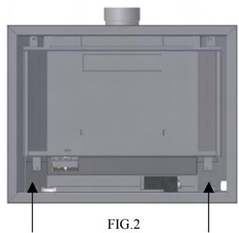
2 Verwijder de vier schroeven van de sierlijst en de sierlijst wegnen (zie fig. 2)
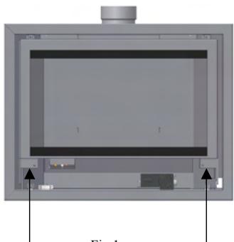
Fig.1
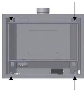
Fig.2
3 Verwijder de twee schroeven van het schoorsteen aansluitstuk en schuif de plaat UIT de rails (zie fig. 3).
4 Monteer de flexibele buis aan het aansluitstuk.
5 Plaats de kachel nu in de ombouw en schuif het schoorsteen aansluitstuk wee op+zijn plaats.
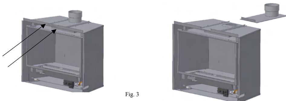
Fig. 3
6 Maak nu de gasaansluiting volgens de voorschriften (zie gasaansluiting)
7 Controller alle gasaansluitingen op gasdichtheid gebruik hiervoor zeepwater of een gaslek detector
8 Monteur nu de ontvanger van de afstandsbediening (zie afstandsbediening)
9 Plaats nu de sierlijst
10 Plaats de houtset (zie plaatsen van de houtset)
11 Plaats het glasaam denk eraan het glas Niet aan te raken omdat vingerafdrukken Nieteer te verwijderen Zijn als de kachel eenmaal hebft gebrand.
2.3 Aansluiten van de schoorsteen.
De gashaard is standard voorzien van een open trekonderbroker met valwindafleider.
Gebruik voor de verbinding vanaf het toestel tot schoorsteenkanaal corrosievast materiaal.
De binnendiameter van de pijp moet minimaal 100mm zijn.
De aansluiting van het toestel op het schoorsteenkanaal dient deugdelijk en lekkagevrij te zich.
2.4 Aansluiting van de gasleiding.
In de gasleiding voor het regelblok dient een goedgekeurde gaskraan van 3/8 geplaatst te worden makkelijk bereikbaar.
De aansluiting op het gasblok is 3 / 8
Na aansluiting van de gasleiding het geheel met zeepwater of een gaslekdetector controleren.
Voorkomijdens montage van de gasleiding spanningen op het gasblok
2.5 Onderhoud.
Om de veiligheid en de goede werkig van de kachel te konnen garanderen dient de kachel Jaarliks door een erkend vakman gecontroleerd en gereinigd te worden.
Het brandergedeelte de waakvlam en de verbrandings kamer.
Het keramisch glas kan gereinigd worden met een speciala schoonmaakmiddel voor keramische kookplaten.
Indien een houtblok stuk is dient每次都ervangen te worden.
Indien er sprake is van een barst in de ruit of als de ruit gebroken is dien deze verrangen te worden alvorens de gashaard wee in gebruik mag worden genomen.
Let op bij het terug plaatsen van de houtblokken dat ze weer in de juiste positie worden geplaatst (zie plaatsen houtset).
2.6 TTB.
Dit toestel is standard voorzien van een open trekonderbreker, valwindafleider en een thermische terugslag beveiliging (TTB).
2.7 Houtset.
Vul erst de branderplaat met de bijgeleverde korrels (zie fig. 4a).
Let op nooit meer korrels gebruiken dan de bijgeleverde hoeveelheid.
Plaats nu de houtblokken volgens fig. 4b en 4c.
Let op dat bij hetplaatsen van de houtblokken geen bloc op de waakvlam geplaatst worden.
Denk er wel aan dat de blokken exact volgens het voorbeeld geplaatst worden om de vlammen zo min möglichk af te Dekken en zo verstoring van het vlambeeld of roeten te voorkomen.
Zorg er voor dat het glasraam goed gesloten worden alvorens de kachel aan te steken.
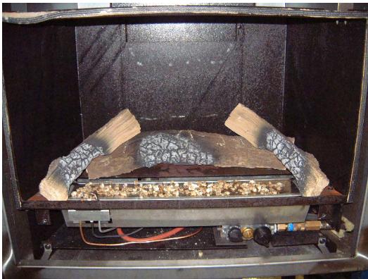
Fig. 4a
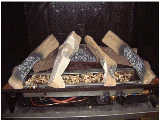
Fig. 4b
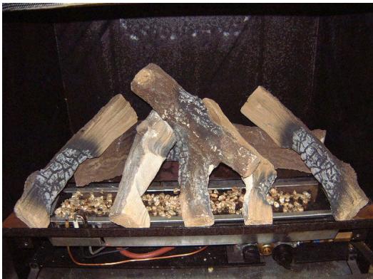
Fig. 4c
2.8 Afstandsbediening.
Plaats de ontvanger van de afstandsbediening links onderin het toestel voordat u de sierlijstplaatst ( fig. 6 ). Schuif de kabelCUSSEN du buitenmantel en de bodem plaat van de verbrandingskamer.
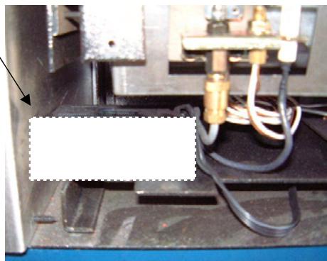
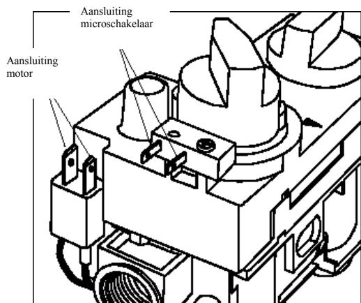
Fig. 6
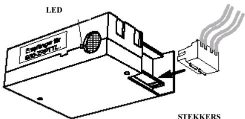
ONTVANGER
STEKKERS
VOOR
MICRO
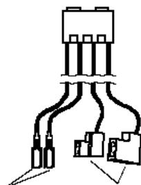
SCHAKELAAR
KABEL
STEKKERS VOOR MOTOR
2.9 Gebruiks aanwijzig afstands bediening.
Instellen van de display (van F/12h maar C/24h en omgekeerd)
Na hetplaaten van de batterij (9v alkaline) of door het te gelijkrijkig indruken van de knoppen AUTO en TIMER begint de aanduiding te knipperenijdens het knipperen van de display kan men omschaken van F waar C door het indruken van de AUTO knop kan men omschaken.
De display za na enigeijd van zich op handbedieningtering keren, men kan ook de knop TIMER indrukken.
Instellen van de tijd.
Na hetplaaten van de batterij of door het gelifiktijdig indrukken van de AUTO en TIMER knop begint de displaye knipperen om de tijd in te stellen moet men () indrukken om de uren in te stellen en met de knop () kan men de minuten instellen aansluitend wachten of op knop TIMER drukken om weer op handbediening terug te keren.
Instellen van de gewenste temperatuur.
De AUTO toets net zolang ingedrukt houden tot de temp aanduiding knippert dan met toets () of () de temperatuur hoger of lager instellen. Daarna wachten of knop AUTO indrukken om in de automatisch modus te komen.
De sensor in de afstands bediening meet de temperatuur in de ruimte.Deze wordt met de ingestelde temperatuur.
vergeleken de ontvanger krijt een signal en stelt de vlam hoogte inaar gelang de temperatuur in de ruimte.
Programming van de timer functie.
De TIMER knop zolang ingedrukt honden tot aanduiding P1* knippert.
Dan met knop (▲) voor uren en knop (▼) voor minuten de inschakelijk instellen en dan nogmaals TIMER indrukken tot P1® verschijnt dan kan men de uitschakelijkijd instellen, door nogmaals TIMER te drukken kan men de toughen voor het tweede programme P2* P2® instellen aansluitend met TIMER bevestigen. Buiten de geprogrammeerde tjden verschijnt het ◆ symbol in beeld.
Gebruik van de verzischlende möglichkheden.
Handbediening van de vlam hoogte.
() indrukken om het vuur in te schakelen of om de vlammen te verhogen, () indrukken om de vlammen te verkleinen of om het toestel op waakvlam te zetten.
Bij het indrukken van deze knopen verschijnt links boven op de display het zend teken is het gasventiel op zich eindaanslag dan begint het led van de ontvanger te knipperen men weet dan dat men de hoogste of laagste stand bereikt hierf.
Temperatuur regeling AUTO
AUTO kort indrukken in de display verschijnt kort de ingestelde temperatuur daarna de ruimte temperatuur.
Timer (TIMER)
Als de timer modus is ingeschakeld is de temperatuur regeling hetzelfde als in de AUTO
modus tijdens de uitschakelrijk schakelt de motor hel toestel op waakvlam.
Ter controle van de ingestelde temperatuur AUTO indrukken en aansluitend in de TIMER modus terugkeren.
Tijdens de uitschakel vrij vind er geen temperatuur controle plaats, het batterij verbruik van de zender is daardoor zeer gering.
Met de toetsen () en () komt men vanuit elkemodus in handbediening.
Het worden aanbevolen omuit te schakelen met de () toets de zender is dan nicht actief en belast daarmee de batterijen Niet onnodig.
Wisselen van de batterijen.
Als er BATT rechts boven in het display verschijnt of als het led lampje op de ontvanger minder duidelijk worden要去 de batterij verrangen worden
Veiligheids uitschakeling
Ontvangt de ontvanger 2=uur lang geen signaal dan worden het toestel automatisch op waakvlam gedraaid als er later waar een signaal komt worden het toestel wee ingeschakeld.
Aanwijzingen.
Voordat men AUTO of TIMER inschakelt moet men met de toetsen () en () de ontvangst testen (als op de zender het zend symbol verzwijnt moet op de ontvanger het led knipperen).
Met de temperatuur regeling worden over de tijd dat de motor draaiit de vlam hoogte ingesteld dezeijd is afhankelijk van de grootte van het vertrek waar het toestel staat opgesteld, van het vermogen van het toestel en batterij sterkte etc.
Een micro processor meet de temperatuur verhoging perijd en corrigeert de draaitijd van de motor tijdens de volgende verwarmingstijd, om de vlamhoogte aan de warmte behoefte aan te passen.
Als dekleinstand voldoende is om het vertrek op te warmen zal het toestel na enkele keren op automaat te hebben gebrandt, tussen kleinstand en uit gaan branden zDat het maybeik is langere brandtijden en eengelijkmatigere temperatuur te bereiken.
Benodigde batterijen: 1x 9v alkaline afstandbediening 4x aa 1,5v penlite ontvanger
3.0 GEBRUIKERS HANDLEIDING
In het midden van het toestel darüber de klep bevinden zich de bedieningsknoppen van de kachel.
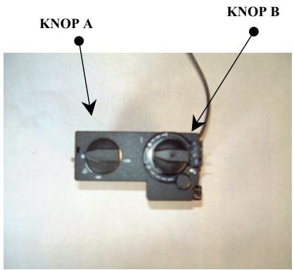
3.1 In gelebruik stellen van de kachel.
Open de gaskraan walke in de gastoevoerleidingaar de gaskachel is gemonteerd. Draai de ontstekingsknop - A - rechtsom in die richting van ontsteken tot aan de aanslag, verwolgens indrukken en enkele seconden wachten.
Vanuit ingedrukte positie verderaar links draaien tot men een klik hoor.
Door de glasuit Aunt U aan de linkerkant van de kachel zien of de waakvlam brand Is dit Niet het geval dan dient U.Deze handelingen te herhalen.
Indien de waakvlam brand, de ontstekingsknop nog 30 seconden ingedrukt houden. En daarna loslaten de waakvlam要去 nu blijven branden.
Dan de knop - A - nog verder door draaienaar links en op het groe vlammetje zetten
De knop - B - kan nu doormiddel van de afstandbediening in de gewenste stand Ingesteld worden traploosussen hoog en laag.
Ervaring leert welke stand voor uw kamer het meest geschikt is.
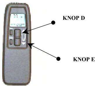
De bediening van de afstandsbediening is eenvoudig knop -D- om de vlam hoger in te stellen en knop -E- om de vlam lager in te stellen of om de vlam geheel te doven.
3.2 Buitenwerking stellen van de hoofdbrander.
Door de knop -E- van de afstandsbediening ingedrukt te houden tot de led lamp op de ontvanger begint te knipperen.
De brander kan ook uitgeschakeld worden door de ontstekingsknop
-A-rechtssom te draaien tot aan de aanslag.
3.3 Buitenwerking stellen van de waakvlam.
Door de ontstekingsknop - A - Licht in te drukken en verder rechtsom te draaien schakelt u de waakvlamuit.
3.4 Voorschriften voor de gebruiker.
Plaats geen brandbare voorwerpen voor, of onderin de gashaard..
Als de gashaard isuitgegaan dan dient men minimaal 10minuten te wachten alvorens de gashaard opniewu te ontsteken (zie in gebruik stellen van het toestel)
Om een goed functioneren van de gashaard te waarborgen adviseren wij om deze minimaal 1 keer peraar te lately reinigen en controleren door een erkend installeur. Indien de gashaard herhaaldelijk afslaat dan dient men de installeur te waarschuwen.
Als warmte wisselend oppervlak worden gezien de voorkant.
Waarschuwing de kachel mag Niet gebruikt worden als de glasruit gebroken is of als de deur open staat. De kachel mag alleen gerepareerd worden met originele onderdelen geleverd door de fabrikant en reparations mogen alleen uitgevoerd worden door een erkend installmenter.
Aan de houtset mag onder geen enkele omstandigheid iets veranderd of toegevoegd worden als er een houtblok stuk is dient deze verrangen te worden door een origineel door de fabrikant geleverd exemplaar. Om brandgevaar uit te sluiten dient de minimum afstand tot brandbare delen en meubels minimaal 100~cm to bedragen de minimum afstandussen dechyterkant van de kachel en de muur dient minimaal 20~cm te zich.
Het is van belang dat u de kachel Niet kort na een verbouwing of nieuwbouw stoekt door de luchtcirculatie worden vocht en nog Niet uitgeharde vluchtige bestanddelenuit sierpleisters, verf, vloerbedekkingen en andere materialen aangezogen. Dit kan op koude oppervlakten roetvlekken verroorzaken.
3.5 TTB beveiling
De kachel is voorzien van een thermische terugslag beveiliging (TTB) dit is een temperatuur schakelaar die in werkig treedt als het afvoerkanaal onvoldoende trek heeft zodat de rookgassen in het vertrek komen, als dit het geval is zal het toesteluitslaan.
De TTB mag nooit buiten werkig gesteld worden.
Bij een defecte TTB dient每次都 met originele onderden verrangen te worden.
Als de TTB de kachel heeft uitgeschakeld dan dient men minstens 10 minuten te wachten tot de kachel wee aangestoken mag worden.
Als de kachel herhaaldelijk uitslaat dient men een installmenter te raadplegen.
Gebruik de kachel Niet tot een erkent installmenter zegt dat het veilig is.
3.6 Eerste keer stoken
Tijdens de eerste maal stoken kan er een onaangename geur ontstaan, die worden veroorzaakt door het inbranden van de但它 bestendige lak. Dit verdwijnt na enkele uren waar raden wij aan het toestel de eerste maal op de hoogste stand te stoken verwijl u tevens het vertrek waarin het toestel staat goed ventiliert.
3.7 Onderhoud.
Om de veiligheid en de goede werkking van de kachel te konnen garanderen dient de kachel Jaarliks door een erkend vakman gecontroleerd en gereinigd te worden.
Het brandergedeelte de waakvlam en de verbrandings kamer.
Het keramisch glas kan gereinigd worden met een special schoonmaakmiddel voor keramische kookplaten.
Indien een houtblok stuk is dient每次都 verrangen te worden.
Indien er spreke is van een barst in de ruit of als de ruit gebroken is dien deze verrangen te worden alvorens de gashaard wee in gebruik mag worden genomen.
Let op bij hetteringplaatsen van de houtblokken dat ze weer in de juiste positie worden geplaatst (zieplaatsen houtset).
3.8 Ventilatic.
De kachel is een zogenaamd open verbrandings toestel dat wil zichgen dat de lustc nodig voor verbranding uit de ruimte gehaald worden hier toestel staat te branden zorg waarom algijd voor voldoende ventilatie.
3.9 Waurschuwing /Advies.
BIJ GEBRUIK VAN DE KACHEL ZULLEN BEPAALDE DELEN ZEER HEET WORDEN LET DAARAM VOORAL OP KLEINE KINDEREN EN OUDEREN ZODAT Z E ZICH NIET VERBRANDEN.
LAAT KINDEREN NOOIT SPELEN MET DE AFSTANDSBEDIERING.
GEBRUK DE AFSTANDSBEDIERING ALLEEN ALS DE KACHEL ZICH IN UW GEZICTSVELD BEVIND.
| A | B | C | D | E | F | G | H | |
| 1 | NL | G25 I2L | 25 | 4,3 | 16 | 380 | 1.4 | 0,501 |
| 2 | BE | G20/G25 I2E+ | 20/25 | 4,3 | 16 | 320 | 1.4 | 0,445 |
| 3 | FR | G20/G25 I2E+ | 20 | 4,3 | 16 | 320 | 1.4 | 0,445 |
| 4 | IT | G20 I2H | 20 | 4,3 | 16 | 320 | 1.4 | 0,445 |
| 5 | DE | G20 I2ELL | 20 | 4,3 | 16 | 320 | 1.4 | 0,445 |
| 6 | AT | G20 I2H | 20 | 4,3 | 16 | 320 | 1.4 | 0,445 |
| 7 | GB | G20 I2H | 20 | 4,3 | 16 | 320 | 1.4 | 0,445 |
| 8 | PT | G20 I2H | 20 | 4,3 | 16 | 320 | 1.4 | 0,445 |
| 9 | ES | G20 I2H | 20 | 4,3 | 16 | 320 | 1.4 | 0,445 |
| 10 | DK | G20 I2H | 20 | 4,3 | 16 | 320 | 1.4 | 0,445 |
| 11 | LU | G20 I2E | 20 | 4,3 | 16 | 320 | 1.4 | 0,445 |
| 12 | SE | G20 I2H | 20 | 4,3 | 16 | 320 | 1.4 | 0,445 |
A:LAND
E:BRANDERDRUK
B: GASSOORT
F:SPUITSTUK CODE
C: VOORDRUK
G: KLEINSTAND SPUITSTUK
D: NOM.BELASTING OW.
H:VERBRUIK Qm/u
Wanders Metaalproducten b.v. te Netterden garandeert gedurende 1aar na aankoopdatum de goede werking van de gashaard, mits het toestel
vakkundig is geinstalleerd en gebruikt volgens de gestelde aanwijzingen.
De garantie omvat alle gebren die te herleiden zich tot constructie- en materiaial foulen en omvat het gratis leveren van neue onderdelen. Arbeidsloon en andere kosten können Niet aan Wanders Metaalproducten b.v. worden doorberekend.
Defecte onderdelen dienen franco te worden toegezonden aan Wanders Metaalproducten b.v. Amtweg 4, 7077 AL Netterden.
Storingen, welke zijn ontstaan door onoordeelkundig gebruik, Niet juiste naleving van de installment- en gebruksvoerschriften, aansluien en reparaties door nicht erkende installeurs, verwaarlozing of ombouwen op een andere gassoort dan waarvoir het toestel is bestemd, vallen buiten iedere vom garantie.
Klachten worden erst dan in behandelung genomen nadat de leverancier / installeur van het toestel of het gasbedrijf de klacht heeft ingediend onder opgaven van aankoopdatum enkopie van de aankoopbon.
Reparaties geenrecht opverlenging van de garantie-terminn. Alle gevolgschade wordenuitgesloten.
BORDEAUX
GAS INSET STOVE
May we take this opportunity to thank you for purchasing one of our products.
While we are constructing our fires, we do not only pay the greatest attention to design and appearance, but also to maximizing user-friendliness and reliability.
We are therefore fully confident that you will enjoy this appliance for years and years to come.
INDEX
0.0 DATA SHEET for the Bordeaux gas inset stove.
4.0 TECHNICAL INSTRUCTIONS FOR FITTER
2.0 INSTRUCTIONS FOR INSTALLATION
2.1 TECHNICAL INSTRUCTIONS
2.2 CHIMNEY REQUIREMENTS
2.3 INSTALLATION OF THE STOVE
2.4 FITTING THE FLUE
2.5 FITTING THE GAS PIPE
2.6 VENTILATION
2.7 TTB SAFETY DEVICE
2.8 MAINTENANCE
2.9 FITTING THE LOG SET
2.9A LOG LAYOUT NATURAL GAS
3.0 USER INSTRUCTIONS
3.1 POSITIONING THE REMOTE CONTROL RECEIVER
3.2 REMOTE CONTROL TECHNICAL SPECIFICATIONS
3.3 REMOTE CONTROL USER INSTRUCTIONS
3.4 OPERATING THE FIRE FOR THE FIRST TIME
3.5 CURING PAINT
3.6 USER GUIDELINES
3.7 EXPLODED VIEW OF STOVE
3.8 TECHNICAL DRAWING OF STOVE
4.0 SERVICE RECORD. TO BE FILLED OUT ANUALLY BY YOUR SERVICE ENGINEER
5.0 STOVE INSTALLATION SPECIFICATION & INFORMATION THIS SECTION TO BE COMPLETED AND SIGNED BY THE INSTALLATION ENGINEER
6.0 WARRANTY
NATURAL GAS (N.G.)
NATURAL GAS (N.G.)
G20 12H
A: COUNTRY
G.B.
B: TYPE OF GAS
G20 12H
C: INPUT
4.3kw
D: OUTPUT (MAX)
3.5kw
E: OUTPUT (MIN)
2.7kw
F: EFFICIENCY
81% (nett)
G: PRESSURE. (STANDING)
20mbar
H: PRESSURE (OPERATING)
16mbar
I: CONSUMPTION (MAX)
0.445m3/hr
J: NOZZLE CODE No.
320
K: LOW FLAME NOZZLE DIAMETER
1.4mm
LIQUEFIED PETROLIUM GAS (L.P.G.) NOT YET AVAILABLE
1. TECHNICAL INSTRUCTIONS FOR FITTER
IMPORTANT
It is important to read these instructions before you install the fire.
After commissioning the installation, go through the operation of the unit with the customer and leave these instructions with them. Make sure that they store these instructions in a safe place.
SECTION 5.0 THIS SECTION TO BE COMPLETED AND SIGNED BY THE INSTALLATION ENGINEER.
Please fill out the STOVE INSTALLATION SPECIFICATION & INFORMATION on the final page of these instructions. Some of the information on the data plate may need to be filled out before the fire is installed as access to the plate is limited once the fire is installed.
2. INSTRUCTIONS FOR INSTALLATION
2.1 Technical instructions.
- The fireplace should be connected and checked by an authorised C.O.R.G.I. gas fitter.
- CHECK THE DATA ON THE DATA PLATE IS CORRECT FOR THE INSTALLATION REQUIREMENTS.
- Do not fit the fire into an unsuitable location.
- Check whether the fireplace is suitable for the type of gas
- Check burner for proper gas type (this is indicated on the data plate)
- Check ventilation requirements, the air needed for the combustion process is extracted from the room in which the fireplace is installed. Make sure that there is enough ventilation.
- The combustion gasses need to be discharged through an appropriate flue.
- The changing of setting values and other adjustments can only be done by an authorised fitter and only according to the requirements.
- A suitable isolation valve, independent of any appliance control must be fitted.
The apparatus must only be installed into a fireproof recess. - When you use an existing smoke channel, ensure that it is sound by carrying out a smoke test.
- Have the smoke channel cleaned by a professional before installing the gas fire.
- Keep to the approved gas fitting requirements.
Overall size of unit: height 552mm width 404mm depth 312mm
There should be approximately 5cm clearance between the recess and the fireplace. - Any manufactured surround that is fitted with this stove must have the appropriate British Standard.
2.2 Chimney requirements
When an appliance has previously been connected to the chimney, the chimney must be cleaned by a professional.
Although a gas fireplace can operate well on a little chimney draw, we advise you to have the chimney checked for soundness and correct operation annually.
An approved gas cowl may be fitted to improve the operation of the chimney. It will prevent lift in windy conditions, eliminate downdraught and stop rain and other foreign bodies entering the flue.
2.3 Installation of the fire.
Remove the packaging carefully. Inspect the fire for any signs of damage.
- To remove the front panel that holds the glass: Remove the two screws behind the fold down door, below the front glass panel (FIG. 1) and lift off the frame and glass window.
- To remove the outer decorative frame surround: Remove the four screws of the decorative frame and carefully pull it out. (FIG. 2).

FIG.1
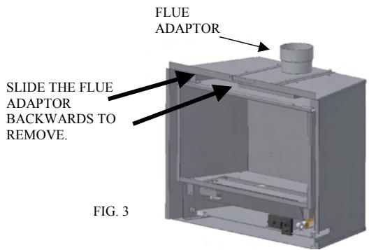
- Remove the two screws of the flue adaptor and slide it out of the rails. (FIG. 3)
- If the chimney is to be lined with a flexible liner, secure this to the flue adaptor using proprietary heat proof sealant. Additional securing may be necessary.
- Now place the fireplace in the recess and slide the flue adaptor piece back into place, screw the two self tapping screws in place to retain it.
5A. The fireplace recess MUST be capable of withstanding the high temperatures generated by such an appliance. - Now make the gas fitting according to the requirements (check 'fitting the gas pipe')
- Make sure all gas fittings are gas proof.
- Position the remote control receiver below the burner (see section 3.1 FIG.6)
- Mount the decorative frame back onto the unit.
- Put the logs (and vermiculite chips) in place, exactly as per instructions. This is critical to the correct operation of the unit. Check (section 2.9) the chapter on the positioning of the log sets, as these vary depending on whether it is L.P.G. or Natural Gas.
- Put the glass window and frame back into place and secure with the two self tapping screws. Remember not to touch the glass, because fingerprints cannot be removed after the fireplace has been lit up without stripping it down.
2.4 Fitting the flue.
The gas fire is fitted with an open draw breaker and downdraught wind diverter.
- The products of combustion must not be able to enter back into the property and therefore the fire must be sealed into the chimney opening, complying with the standard in force at that time. A flexible flue may need to be fitted.
- For the connection between the apparatus and the chimney terminal / channel, use of corrosion free material; that must comply with the latest standards in force at that time; must be used and adequately sealed and attached at each end. The inner diameter of the pipe should be at least 100mm .
- The connection between the apparatus and the chimney channel should be sound and free of leakage and must be one continuous length with no other joints.
2.5 Fitting the gas pipe.
- An approved gas isolation tap should be fitted in the gas pipe that leads to the appliance, this tap should be easily accessible.
- A minimum, 15 mm diameter gas supply pipe should be used to within 1 meter of the appliance.
- The final connection to the appliance must be made in 8mm semi-rigid gas pipe. This must be less than 1 meter in length. The inlet valve has an 8mm nut and olive supplied.
- Avoid tension on the gas block when fitting the gas pipe. Support the unit if necessary.
- Check the entire unit for soundness after fitting the gas pipe.
2.6 Ventilation.
The fireplace is a so-called 'open combustion apparatus', which means that the air needed for the combustion process is extracted from the room in which the fireplace is installed.
It is important to have enough ventilation in this room. Although the appliance is rated at less than 7kw input, additional ventilation may be necessary in certain circumstances.
2.7 TTB
This apparatus is equipped with TTB safety mechanism, this shuts off the gas supply to the burner when the chimney is blocked. If this is the case, the apparatus will shut down.
When this happens, it is usually an indication of a problem with the chimney. If this is found to be o.k. then check the pilot/gas supply.
2.8 Maintenance.
In order to ensure the safe and correct operation of the gas fire, it should be serviced and cleaned by an authorised professional annually.
There is an annual service record at the back of these instructions that should be filled out each time the appliance is serviced.
The service should include the burner unit, the pilot flame failure device and the combustion chamber.
The ceramic logs should also be inspected for signs of wear and tear. If a log is broken, it should be replaced. Correct positioning of the logs is critical. (check the chapter on the log sets).
The ceramic glass can be cleaned with a special cleaning product for ceramic cookers or one from your local stockiest.
The decorative frame should be wiped with a lint free cloth or soft brush.
If there is a crack in the glass window, or if the window is broken, it should be replaced before the gas fireplace can be lit up again.
Ensure that the pilot is operating correctly.
2.9 FITTING THE LOG SET
- THE CERAMICS VARY DEPENDING ON WHETHER THE FIRE IS SET TO RUN ON NATURAL GAS OR L.P.G.
- REFER TO THE PICTURES ON THE NEXT PAGES TO ASSIST CORRECT POSITIONING OF THE CERAMICS.
Take great care when handling the ceramic logs as they are very fragile.
Refer to the diagrams when laying the logs. - Only use the logs supplied with the fire and NEVER use alternatives or extra coals or logs.
Incorrect positioning of the ceramics will cause combustion problems within the fire.
2.9A Fitting the Log set- natural gas.
- Firstly, fill the burner plate with the enclosed vermiculite chips (check fig 4a). A thin level layer is ideal.
Caution: never use more grains than the supplied amount.
- Now put the logs in place according to fig. 4b and 4c.
Make sure that when you are putting the logs in place, the pilot flame is not obstructed by either a log or vermiculite chips.
The logs must be put in exactly as per these instructions. This is in order to ensure that the flames are impinged as little as possible and thus preventing the disturbance of the flame pattern and possible sooting.
- Replace the glass window and make sure that it is firmly shut before you light the fire.
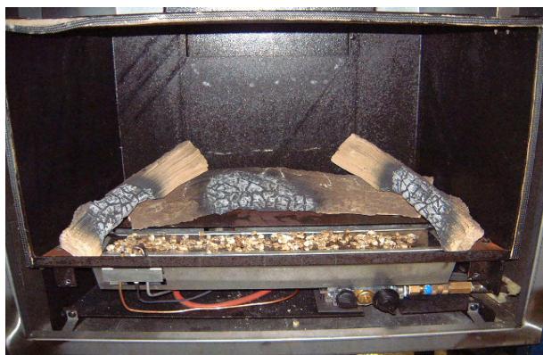
FIG 4A
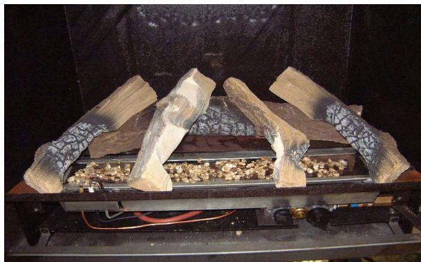
FIG 4B
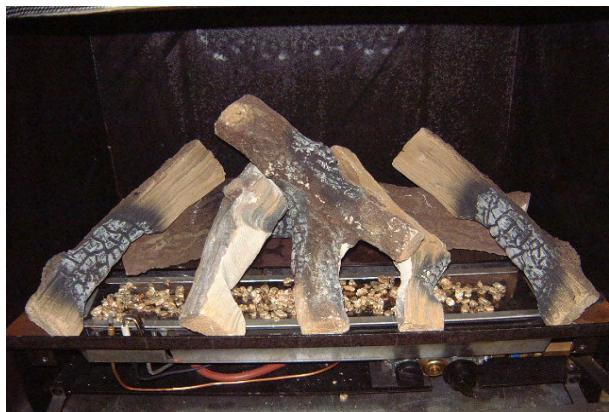
FIG 4C
3.0 USER INSTRUCTIONS
3.1 POSITIONING THE REMOTE CONTROL RECEIVER.
Place the remote control receiver in the bottom left corner of the unit before you mount the decorative frame (check FIG. 6).
Slide the cable between the outer casing and the bottom of the combustion chamber. (check FIG. 6).
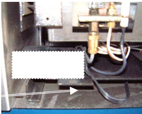
FIG. 6
3.2 REMOTE CONTROL
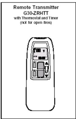
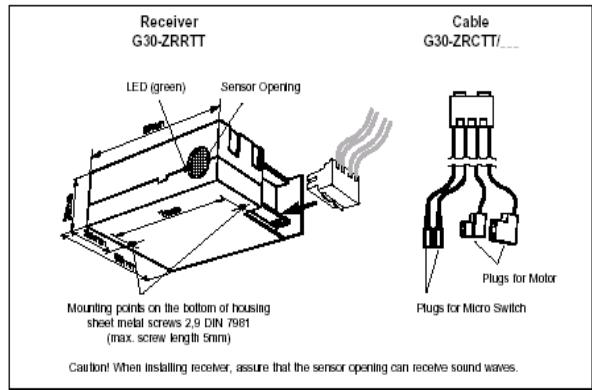
Illustration 1: Components of the Ramiola Package
TECHNICAL SPECIFICATIONS
Ultrasound Transmission:
Ambient Temperature:
Range:
1...10m
3...33ft.
Frequency:
ON 40,5kHz,
OFF 40kHz
Transmitter & Receiver:
max. 60^ 140°F
Connecting Cables:
max. 180^ 356°F
Batteries required:
Handset: 1 x 9V block (alkaline recommended)
Receiver: 4 × 1,5V AA (alkaline recommended)
CONNECTIONS
The G30-ZRPTT is intended for use only with motorized gas combination controls models GV34
(or GV36 retrofitted with a motor). The receiver cable must be firmly plugged onto the flat blade
connectors. motor: 6,3 and 4,8mm
micro switch: both 2,8mm
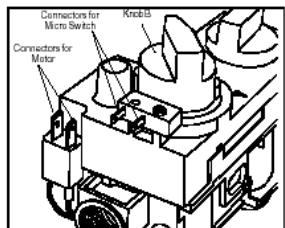
Illustration 2: Cover with Connectors for Micro Switch
3.3 REMOTE CONTROL OPERATING INSTRUCTIONS
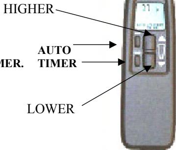
The two large buttons on the remote control hand-set are used to operate the main burner.
The two smaller buttons are for AUTO and TIMER.
Instructions for their use follow.
SETTING THE DISPLAY
After fitting the batteries in the receiver and the hand set, the following options are available:
Adjustment of the digital display (from 'DEGREES F & 12 HOUR' to 'DEGREES C & 24 HOUR' and vice versa)
- Press the buttons AUTO and TIMER at the same time until the display blinks.
Now you can switch from F to C and vice-versa by pressing the AUTO button.
The display will return to "manual operation" after a short time.
SETTING THE TIME
- Press the buttons AUTO and TIMER at the same time, the indications on the screen start to blink.
To set the time, the button must be pressed to set the hours. The button will set the minutes.
To return to manual operation, you need to wait several seconds or push the TIMER button.
SETTING THE DESIRED AUTOMATIC TEMPERATURE
- Press the AUTO button until the "temperature" indication starts to blink.
- Then set the desired temperature by means of the or button.
After that, wait or press AUTO to get to the automatic mode.
The sensor in the remote control measures the temperature in the room. The receiver on the stove compares the room temperature with the pre-set temperature and if necessary, adjusts the height of the flames automatically.
PROGRAMMING THE TIMER FUNCTION
- Keep TIMER button pressed until indication P1 starts to blink.
- Then set the switch-on time by means of the buttons for hours and for minutes.
- Press TIMER again, until P1 appears. Then the switch-off time can be set.
- By pressing TIMER once again, the times for the second program, P2 can be set.
The set times must be confirmed by pressing TIMER again.
Outside the programmed times the symbol D will appear.
MANUAL MODE
ADJUSTING THE HEIGHT OF THE FLAMES MANUALLY, ONCE THE PILOT HAS BEEN LIT.
- Press (HIGHER) to start the fire or to make the flames higher. Press (LOWER) to make the flames smaller or to switch the fire to the PILOT ON position. On pressing these buttons, the "send" sign will appear in the upper left corner of the display on the handset display.
- When the gas valve has reached its maximum position (open or closed), the LED of the receiver will start blinking, indicating that the highest or lowest position is reached.
AUTOMATIC MODE 'AUTO' in display
Use this mode to set the desired temperature that you would like the room to stay at.
Press and hold the AUTO button until the display flashes.
- Press either of the buttons () and () to set the desired temperature.
- Wait a few seconds until the set temperature stops flashing or press AUTO to switch to AUTO MODE.
TIMER 'TIMER' IN DISPLAY
Use this mode to switch the Stealth on and off automatically at the times set.
If the timer mode is switched on, temperature control is done in the same way as in the AUTO mode. As soon as the 'heating cycle off' time is reached, the Stealth will switch to the
PILOT ON position and there is no temperature control. This minimizes battery consumption.
SWITCHING THE FIRE OFF
We recommend to switch the fire off using the () button; the transmitter will then not be active and will not use up any energy from the batteries.
By pressing either of the buttons () and () , you will reach "manual operation", from any other mode.
CHANGING THE BATTERIES
If "BATT" appears in the top right corner of the display, or if the LED light on the receiver becomes less bright, the batteries needs to be changed.
AUTOMATIC SAFETY SWITCH-OFF:
If the receiver does not receive any signal during a 2 hour period, the unit will switch to the pilot light mode automatically and will switch on again as soon as a new signal is sent.
This may happen for example if the remote control was accidentally removed from the property.
Required batteries:
1x 9v, alkaline for the remote control and 4x AA, 1,5v penlight for the receiver.
3.4 OPERATING THE FIRE FOR THE FIRST TIME
In the middle of the apparatus, below the main glass there is a drop down door that hides the main controls. (shown below)
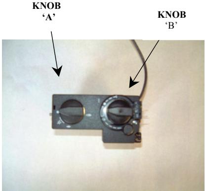
- Open the gas tap which is mounted in the gas pipe leading to the fireplace.
- Turn the ignition button (A) clockwise, all the way to the end stop. This is the START (OFF) position for the pilot.
- Depress and turn it anti-clockwise until you hear a click. This is the spark that ignites the pilot being generated.
3A You will be able to see though the glass window, in the front left corner, if the pilot flame has lit. - If the pilot did not light, repeat the previous sequence. (from 2)
- If the fire goes out, do not re-ignite for at least 3 minutes.
- If the pilot flame is burning, keep the ignition button pressed for at least 15 seconds, then let it go. The pilot flame should still be burning.
- Now turn button (A) further anti-clockwise, this opens the valve and allows operation of knob (B).
- Knob (B) can now be set (continuously variable) at the desired setting between high and low, manually simply by turning anti-clockwise for higher, clockwise for lower. Or by using the remote control.
You will learn which setting is most suitable for your room through experience.
Operating the remote control is easy. See previous paragraph for details.
3.5 CURING PAINT
After lighting the fire for the first time, an unpleasant scent may develop.
This is caused by the hardening of the heat resistant lacquer on the stove, this scent will disappear after several hours. We therefore advise you to set the flame height as high as possible when you light up the fire for the first time and to ventilate the room in which it is installed.
3.6 USER GUIDELINES.
- Do not use the fire until an authorised fitter has commissioned the unit and carried out the required safety tests.
- The TTB fitted to this appliance is not a substitute for an independently fitted carbon monoxide detector.
- Do not place any combustible objects within 1 meter of the appliance.
When the fire has extinguished you must wait at least 3 minutes before you ignite it again (check taking the fireplace into operation).
- In order to ensure the safe and correct operation of the gas fire, it should be checked and cleaned by an authorised professional annually.
- If the fire in the gas fireplace extinguishes repeatedly you should consult your fitter.
- If you ever smell gas, switch the appliance off at the burner control and the isolation tap.
The front of the gas fireplace is regarded as the heat exchanging surface. - The fireplace may not be used when the glass window is broken or when the door is open.
- The fireplace may only be repaired using original parts supplied by the manufacturer, and repairs may only be done by an authorised fitter.
- You cannot alter or add anything to the log set under any circumstance. If a log is broken, it should be replaced by an original one supplied by the manufacturer.
- The distance between the fireplace and combustible objects or furniture should be at least 1 meter.
- It is important that you do not use the fireplace shortly after a renovation or in a newly built house. The air circulation sucks moisture and unhardened volatile elements of plaster, paint, floor coverings and other materials into the fireplace. This may cause soot stains on cold surfaces.
- NEVER LET CHILDREN PLAY WITH THE REMOTE CONTROL.
- ONLY USE THE REMOTE CONTROL WHEN THE FIREPLACE IS IN YOUR VIEW.
- WHEN THE FIREPLACE IS IN OPERATION, CERTAIN PARTS WILL BECOME VERY HOT. IT MAY BE NECESSARY TO FIT A GUARD TO PROTECT CHILDREN, THE ELDERLY AND INFIRM.
- Cleaning of the stove should only be carried out when it is cold.
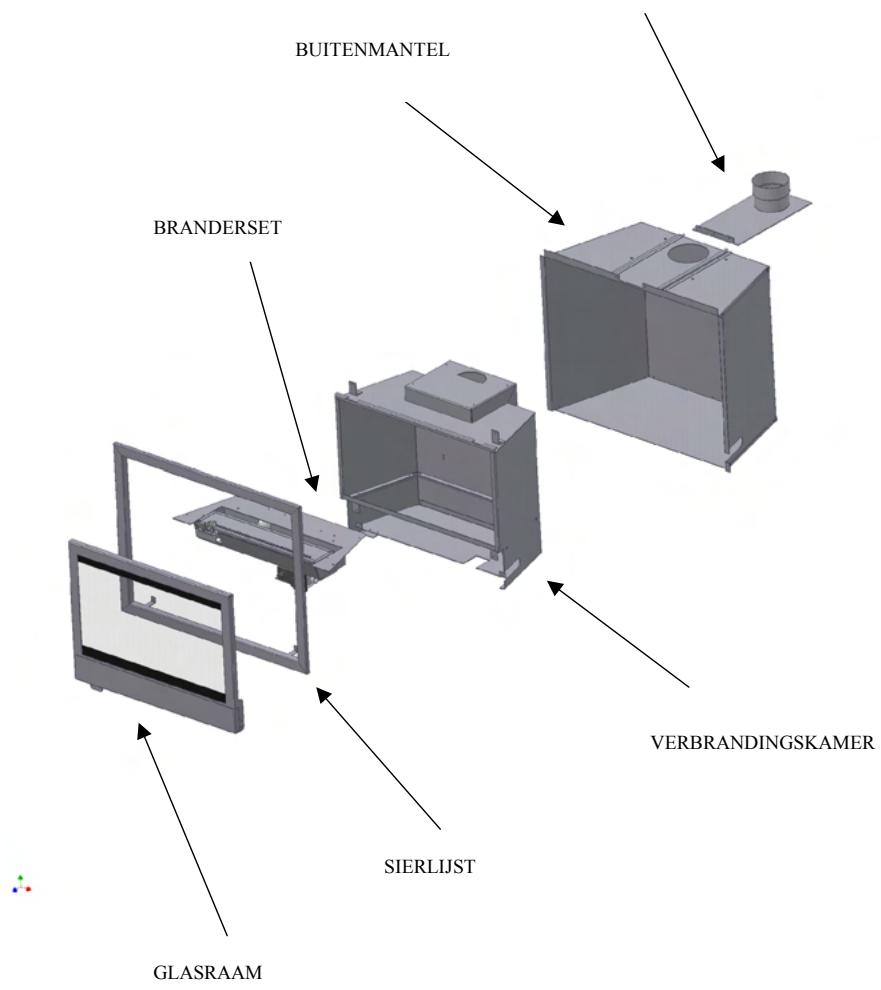
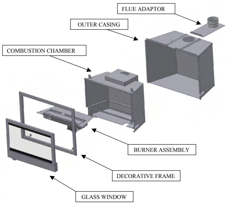
EXPLODED VIEW OF STOVE COMPONENTS
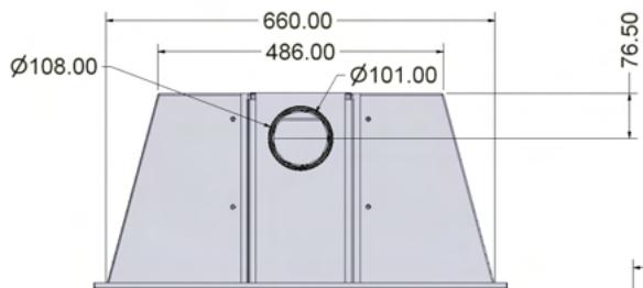
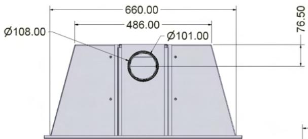
TECHNICAL DRAWING
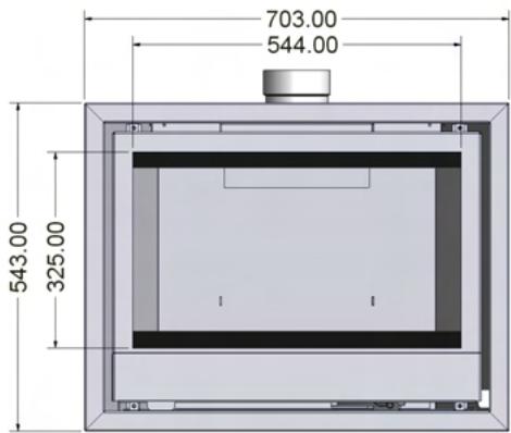
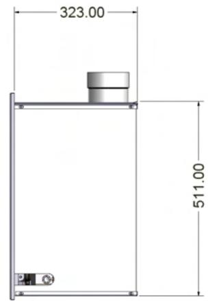
ANNUAL SERVICE RECORD
INSTALLATION DATE OF APPLIANCE:
IST YEAR SERVICE completion date:
SERVICE ENGINEER:
COMPANY NAME:
COMPANY ADDRESS:
POSTCODE:
CONTACT NUMBER
2ND YEAR SERVICE completion date:
SERVICE ENGINEER:
COMPANY NAME:
COMPANY ADDRESS:
POSTCODE:
3RD YEAR SERVICE completion date:
SERVICE ENGINEER:
COMPANY NAME:
COMPANY ADDRESS:
POSTCODE:
4TH YEAR SERVICE completion date:
SERVICE ENGINEER:
COMPANY NAME:
COMPANY ADDRESS:
POSTCODE:
5TH YEAR SERVICE completion date:
SERVICE ENGINEER:
COMPANY NAME:
COMPANY ADDRESS:
POSTCODE:
6TH YEAR SERVICE completion date:
SERVICE ENGINEER:
COMPANY NAME:
COMPANY ADDRESS:
POSTCODE:
STOVE INSTALLATION SPECIFICATION & INFORMATION
THIS SECTION TO BE COMPLETED AND SIGNED BY THE INSTALLATION ENGINEER
Type gas supply (please tick)
Natural (mains) Gas LPG supply in bulk LPG supply in cylinder
Size of Governor setting: (i.e.) Natural Gas 20MBAR. LPG 37MBAR)
Length and size of gas supply:
Meter pressure. Fire on only:
Other appliances. All on:
Burner pressure. Fire on only
Other appliances. All on:
Gas rate - Natural Gas - Time for 1 cubic foot in seconds:
Overall length of flue:
Is there any spillage: Is the draught excessive:
Is there any permanent ventilation in the room:
Has the room double glazing:
Is the aeration of the pilot correct:
Does the flame encircle the FFD:
Installation Engineers Name:
Address
Post Code
Telephone: Fax: Mobile:
Corgi Registration No:
Signed:
Date:
Guarantee
Dear Customer,
Your gas fire, when installed in accordance with the installation instructions and operated in accordance with these instructions, should provide many years of safe and efficient operation.
We thank you for purchasing our product and trust it will provide excellent service.
This appliance carries a guarantee of 2 Years from date of purchase.
The guarantee is void if:
The appliance is not installed and operated in accordance with our instructions, or
- repairs of modification have been carried out by the purchaser or any third party not authorised by us or:
the appliance has been misused or accidentally damaged, or:
damage is due to 'fair wear and tear.' or:
the appliance or defective component(s) are not returned to us, prepaid postage.
This guarantee does not cover the consumable items within the appliance, nor the glass.
The rights given in this guarantee are limited to the UK mainland and are in addition to any to which you may have a statutory entitlement.
Please retain your purchase receipt. We will need to see this in the event of a claim under warranty.
Broseley Fires Ltd.
Knights Way,
Battlefield Enterprise Park,
Shrewsbury ,
Shropshire.
SY1 3AB.
Tel: 01743 461444
Fax: 01743 461446
http://www.broseleyfires.com

Ink.00.7066
Wanders
METAALPRODUCTEN B.V.
AMTWEG4
7077 AL Netterden (NL)
Tel. +31 (0)315-386414
Fax +31 (0)315-386201
e-mail: info@wanders.nl
www.wanders.com
- BORDEAUX
- INHOUDSOPGAVE
- TECHNISCHE AANWIJZINGEN VOOR INSTALLATEUR
- INSTALLATIE VOORSCHRIFTEN
- GEBRUIKERS HANDLEIDING
- MANUAL GB PAGE 17
- TECHNISCHE AANWIJZINGEN VOOR INSTALLATEUR
- Belangrijk
- INSTALLATIE VOORSCHRIFTEN
- Technische aanwijzingen.
- Schoorsteen.
- Installeren van de kachel.
- Aansluiten van de schoorsteen.
- Aansluiting van de gasleiding.
- Onderhoud.
- TTB.
- Houtset.
- Afstandsbediening.
- Gebruiks aanwijzig afstands bediening.
- Instellen van de display (van F/12h maar C/24h en omgekeerd)
- Instellen van de tijd.
- Instellen van de gewenste temperatuur.
- Programming van de timer functie.
- Gebruik van de verzischlende möglichkheden.
- Handbediening van de vlam hoogte.
- Temperatuur regeling AUTO
- Timer (TIMER)
- Wisselen van de batterijen.
- Veiligheids uitschakeling
- Aanwijzingen.
- In gelebruik stellen van de kachel.
- Buitenwerking stellen van de hoofdbrander.
- Buitenwerking stellen van de waakvlam.
- Voorschriften voor de gebruiker.
- Als de gashaard isuitgegaan dan dient men minimaal 10minuten te wachten alvorens de gashaard opniewu te ontsteken (zie in gebruik stellen van het toestel)
- TTB beveiling
- De TTB mag nooit buiten werkig gesteld worden.
- Eerste keer stoken
- Onderhoud.
- Ventilatic.
- Waurschuwing /Advies.
- INDEX
- DATA SHEET for the Bordeaux gas inset stove.
- TECHNICAL INSTRUCTIONS FOR FITTER
- USER INSTRUCTIONS
- NATURAL GAS (N.G.)
- TECHNICAL INSTRUCTIONS FOR FITTER
- IMPORTANT
- SECTION 5.0 THIS SECTION TO BE COMPLETED AND SIGNED BY THE INSTALLATION ENGINEER.
- INSTRUCTIONS FOR INSTALLATION
- Technical instructions.
- Chimney requirements
- Installation of the fire.
- Fitting the flue.
- Fitting the gas pipe.
- Ventilation.
- TTB
- Maintenance.
- FITTING THE LOG SET
- 2.9A Fitting the Log set- natural gas.
- POSITIONING THE REMOTE CONTROL RECEIVER.
- REMOTE CONTROL
- TECHNICAL SPECIFICATIONS
- CONNECTIONS
- REMOTE CONTROL OPERATING INSTRUCTIONS
- SETTING THE DISPLAY
- SETTING THE TIME
- SETTING THE DESIRED AUTOMATIC TEMPERATURE
- PROGRAMMING THE TIMER FUNCTION
- MANUAL MODE
- AUTOMATIC MODE 'AUTO' in display
- TIMER 'TIMER' IN DISPLAY
- SWITCHING THE FIRE OFF
- CHANGING THE BATTERIES
- AUTOMATIC SAFETY SWITCH-OFF:
- OPERATING THE FIRE FOR THE FIRST TIME
- CURING PAINT
- USER GUIDELINES.
- EXPLODED VIEW OF STOVE COMPONENTS
- TECHNICAL DRAWING
- ANNUAL SERVICE RECORD
- POSTCODE:
- STOVE INSTALLATION SPECIFICATION & INFORMATION
- THIS SECTION TO BE COMPLETED AND SIGNED BY THE INSTALLATION ENGINEER
- Guarantee
- Wanders
Marque : WANDERS
Modèle : ORSANNE
Catégorie : Cheminée insert