HT1000 - Projecteur NEC - Notice d'utilisation et mode d'emploi gratuit
Retrouvez gratuitement la notice de l'appareil HT1000 NEC au format PDF.

| Intitulé | Description |
|---|---|
| Type de produit | Projecteur DLP |
| Résolution native | 1280 x 720 pixels (HD) |
| Luminosité | 3000 lumens |
| Contraste | 2000:1 |
| Alimentation électrique | 100-240V, 50/60Hz |
| Dimensions approximatives | 300 x 230 x 100 mm |
| Poids | 2,5 kg |
| Compatibilités | HDMI, VGA, Composite Video |
| Type de batterie | Non applicable (projecteur secteur) |
| Tension | 100-240V AC |
| Puissance | 250W |
| Fonctions principales | Projection d'images et de vidéos, connectivité multiple |
| Entretien et nettoyage | Nettoyage régulier du filtre, remplacement de l'ampoule selon l'utilisation |
| Pièces détachées et réparabilité | Disponibilité de pièces de rechange, réparabilité modérée |
| Sécurité | Conforme aux normes de sécurité CE, protection contre la surchauffe |
| Informations générales | Idéal pour les présentations en entreprise et les projections à domicile |
FOIRE AUX QUESTIONS - HT1000 NEC
Questions des utilisateurs sur HT1000 NEC
0 question sur cet appareil. Repondez a celles que vous connaissez ou posez la votre.
Poser une nouvelle question sur cet appareil
Téléchargez la notice de votre Projecteur au format PDF gratuitement ! Retrouvez votre notice HT1000 - NEC et reprennez votre appareil électronique en main. Sur cette page sont publiés tous les documents nécessaires à l'utilisation de votre appareil HT1000 de la marque NEC.
MODE D'EMPLOI HT1000 NEC
HT1000
Entertainment Projector
User's Manual
English
Deutsch
Français
Italiano
Espanol
Svenska
Safety Cautions
Precautions
Please read this manual carefully before using your NEC HT1000 Projector and keep the manual handy for future reference. Your serial number is located on the bottom of your projector. Record it here:

CAUTION
To turn off main power, be sure to remove the plug from power outlet.
The power outlet socket should be installed as near to the equipment as possible, and should be easily accessible.

CAUTION
TO PREVENT SHOCK, DO NOT OPEN THE CABINET. NO USER-SERVICEABLE PARTS INSIDE. REFER SERVICING TO QUALIFIED NEC SERVICE PERSONNEL.

This symbol warns the user that uninsulated voltage within the unit may be sufficient to cause electrical shock. Therefore, it is dangerous to make any kind of contact with any part inside of the unit.

This symbol alerts the user that important information concerning the operation and maintenance of this unit has been provided.
The information should be read carefully to avoid problems.
WARNING
TO PREVENT FIRE OR SHOCK, DO NOT EXPOSE THIS UNIT TO RAIN OR MOISTURE.
DO NOT USE THIS UNIT'S GROUNDED PLUG WITH AN EXTENSION CORD OR IN AN OUTLET UNLESS ALL THREE PRONGS CAN BE FULLY INSERTED.
DO NOT OPEN THE CABINET.THERE ARE HIGH-VOLTAGE COMPONENTS INSIDE. ALL SERVICING MUST BE DONE BY QUALIFIED NEC SERVICE PERSONNEL.
DOC Compliance Notice
This Class B digital apparatus meets all requirements of the Canadian Interference-Caising Equipment Regulations.
Acoustic Noise Information Ordinance -3. GSGV:
The sound pressure level is less than 70 dB (A) according to ISO 3744 or ISO 7779.
RF Interference
WARNING
The Federal Communications Commission does not allow any modifications or changes to the unit EXCEPT those specified by NEC Solutions (America), Inc. in this manual. Failure to comply with this government regulation could void your right to operate this equipment. This equipment has been tested and found to comply with the limits for a Class B digital device, pursuant to Part 15 of the FCC Rules. These limits are designed to provide reasonable protection against harmful interference in a residential installation. This equipment generates, uses, and can radiate radio frequency energy and, if not installed and used in accordance with the instructions, may cause harmful interference to radio communications. However, there is no guarantee that interference will not occur in a particular installation. If this equipment does cause harmful interference to radio or television reception, which can be determined by turning the equipment off and on, the user is encouraged to try to correct the interference by one or more of the following measures:
- Reorient or relocate the receiving antenna.
- Increase the separation between the equipment and receiver.
- Connect the equipment into an outlet on a circuit different from that to which the receiver is connected.
- Consult the dealer or an experienced radio / TV technician for help.
In UK, a BS approved power cable with moulded plug has a Black (five Amps) fuse installed for use with this equipment. If a power cable is not supplied with this equipment please contact your supplier.
Important Safeguards
These safety instructions are to ensure the long life of your projector and to prevent fire and shock. Please read them carefully and heed all warnings.
Installation
- For best results, use your projector in a darkened room.
- Place the projector on a flat, level surface in a dry area away from dust and moisture.
- Do not place your projector in direct sunlight, near heaters or heat radiating appliances.
- Exposure to direct sunlight, smoke or steam can harm internal components.
- Handle your projector carefully. Dropping or jarring can damage internal components.
- Do not place heavy objects on top of the projector.
- If you wish to have the projector installed on the ceiling:
a. Do not attempt to install the projector yourself.
b. The projector must be installed by qualified technicians in order to ensure proper operation and reduce the risk of bodily injury.
c. In addition, the ceiling must be strong enough to support the projector and the installation must be in accordance with any local building codes.
d. Please consult your dealer for more information.
Fire and Shock Precautions
- Ensure that there is sufficient ventilation and that vents are unobstructed to prevent the build-up of heat inside your projector. Allow at least 3 inches (10 cm) of space between your projector and a wall.
- Prevent foreign objects such as paper clips and bits of paper from falling into your projector.
Do not attempt to retrieve any objects that might fall into your projector. Do not insert any metal objects such as a wire or screwdriver into your projector. If something should fall into your projector, disconnect it immediately and have the object removed by a qualified NEC service personnel.
- Do not place any liquids on top of your projector.
- Do not look into the lens while the projector is on. Serious damage to your eyes could result.
- Keep any items such as magnifying glass out of the light path of the projector. The light being projected from the lens is extensive, therefore any kind of abnormal objects that can redirect light coming out of the lens, can cause unpredictable outcome such as fire or injury to the eyes.
- Do not cover the lens with the supplied lens cap or equivalent while the projector is on. Doing so can lead to melting of the cap and possibly burning your hands due to the heat emitted from the light output.
- The projector is designed to operate on a power supply of 100-120 or 200 - 240V50 / 60Hz AC. Ensure that your power supply fits this requirement before attempting to use your projector.
- Handle the power cable carefully and avoid excessive bending. A damaged cord can cause electric shock or fire.
- If the projector is not to be used for an extended period of time, disconnect the plug from the power outlet.
- Do not touch the power plug during a thunderstorm. Doing so can cause electrical shock or fire.
CAUTION
- Do not try to touch the ventilation outlet on the front and side as it can become heated while the projector is turned on.
- Do no use the tilt-foot for purposes other than originally intended. Misuses such as gripping the tilt-foot or hanging on the wall can cause damage to the projector.
- Enable High-Speed Fan mode if you continue to use the projector for consecutive days. (From the Advanced menu, select [Projector Options] [Setup] [Page 4] [High Speed Fan Mode].)
- Do not unplug the power cable from the wall outlet under any one of the following circumstances.
Doing so can cause damage to the projector:
- While the Hour Glass icon appears.
- While the message "Please wait a moment." appears. This message will be displayed after the projector is turned off.
-
While the cooling fans are running. (The cooling fans continue to work for 90 seconds after the projector is turned off).
-
Do not eject the PC card while its data is being accessed. Doing so can damage your PC card data.
- Do not hold the lens part with your fingers. Doing so could pinch fingers or hands causing injury.
Lamp Replacement
To replace the lamp, follow all instructions provided on page E-48.
- Be sure to replace the lamp when the message "The lamp has reached the end of its usable life. Please replace the lamp." appears. If you continue to use the lamp after the lamp has reached the end of its usable life, the lamp bulb may shatter, and pieces of glass may be scattered in the lamp case. Do not touch them as the pieces of glass may cause injury.
If this happens, contact your NEC dealer for lamp replacement.
- Allow a minimum of 90 seconds to elapse after turning off the projector. Then turn off the main power switch, disconnect the power cable and allow 60 minutes to cool the projector before replacing the lamp.
What's in the Box?
Make sure your box contains everything listed. If any pieces are missing, contact your dealer.
Please save the original box and packing materials if you ever need to ship your HT1000 Projector.
Lens cap (24FT8661)
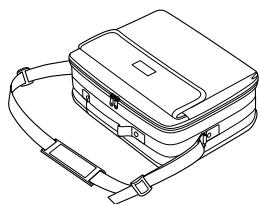
Soft carrying case (24BS7111)
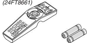
Remote control (7N900371)

String and rivet (24C05051) (24C04531)
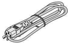
Power cable (7N080204: North America) (7N080003: G model)

RGB signal cable (7N520001)
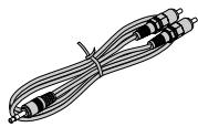
Audio cable (7N520014)

Composite video cable (7N520016)
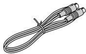
S-Video cable (7N520015)
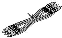
Component video cable (RCA × 3-to-RCA × 3) (7N520017)
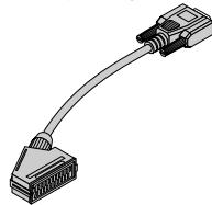
For Europe only
SCART adapter (7N520018)
For North America only
Registration card
Limited warranty
For Europe only Guarantee policy
TABLE OF CONTENTS
IMPORTANT INFORMATION E-2
Safety Cautions E-2
What's in the Box? E-3
INTRODUCTION E-5
Introduction to the Projector E-5
Part Names of the Projector E-6
Attaching the lens cap E-6
Top Features E-7
Terminal Panel Features E-8
Part Names of the Remote Control E-9
Battery Installation E-10
Remote Control Precautions E-10
Operating Range E-10
INSTALLATION AND CONNECTIONS .E-11
Setting Up the Screen and the Projector E-11
Selecting a Location E-11
Throw Distance and Screen Size E-12
Making Connections E-13
Wiring Diagram E-13
Connecting Your VCR or Laser Disc Player . E-14
Connecting Your DVD Player E-15
Connecting Your PC or Macintosh Computer . E-16
When Viewing a DVI Digital Signal E-17
Connecting the Supplied Power Cable. E-17
PROJECTING AN IMAGE (BASIC OPERATION) E-18
Turning on the Projector. E-18
Selecting a Source E-19
Adjusting the Picture Size and Position E-19
Correcting the Horizontal and Vertical Keystone Distortion (3D Reform) ..E-20
Optimizing RGB Picture Automatically E-21
Turning Up or Down Volume E-22
Turning off the Projector E-22
CONVENIENT FEATURES E-23
Using Sweet Vision function. E-23
Using Zoom Position E-23
Turning Off the Image and Sound E-24
Freezing a Picture E-24
Enlarging and Moving a Picture E-24
Getting the On-line Help E-24
Changing Background Logo E-25
USING THE VIEWER E-26
Making the Most out of the Viewer Function E-26
Operating the Viewer Function from the Projector (playback) E-27
Projecting slides (Viewer) E-27
Auto Play Mode E-28
Switching to Slides Directly from Other Input Modes E-28
Viewing Digital Images E-28
Storing Images Displayed on the Projector on the PC card (Capture) .... E-28
Deleting Captured Images E-29
Using the PC Card Files Fucntion (PC Card Files) E-29
USING ON-SCREEN MENU E-30
Basic Menu Operation E-30
Using the Menus E-30
Customizing the Menu E-30
Menu tree E-31
Menu Elements E-34
Entering Alphanumeric Characters by Using the Menu E-35
Menu Descriptions & Functions E-35
Source Select E-35
Video/S-Video/Component/RGB/DVI (DIGITAL)/Viewer/Entry List
Image Options E-36
Selecting Aspect Ratio E-36
Masking Unwanted Area (Blanking) E-38
Adjusting Position and Clock E-38
Zoom Position E-38
Selecting Resolution E-38
Selecting Overscan Percentage E-38
Selecting Video Filter Level E-38
Selecting Noise Reduction Level E-38
Selecting Signal Type E-38
Picture Management E-38
Picture E-39
User Adjust (when using User 1 to 4) E-39
Selecting Reference Setting E-39
Selecting Gamma Correction Mode E-39
Selecting Color Correction E-39
Adjusting Color Temperature and White Balance E-39
Picture Options E-39
Sweet Vision/3D Y/C Separation/Deinterlace/Black Expansion/Contrast Enhancement
Projector Options E-40
Using 3D Reform E-40
Keystone E-40
Cornerstone E-40
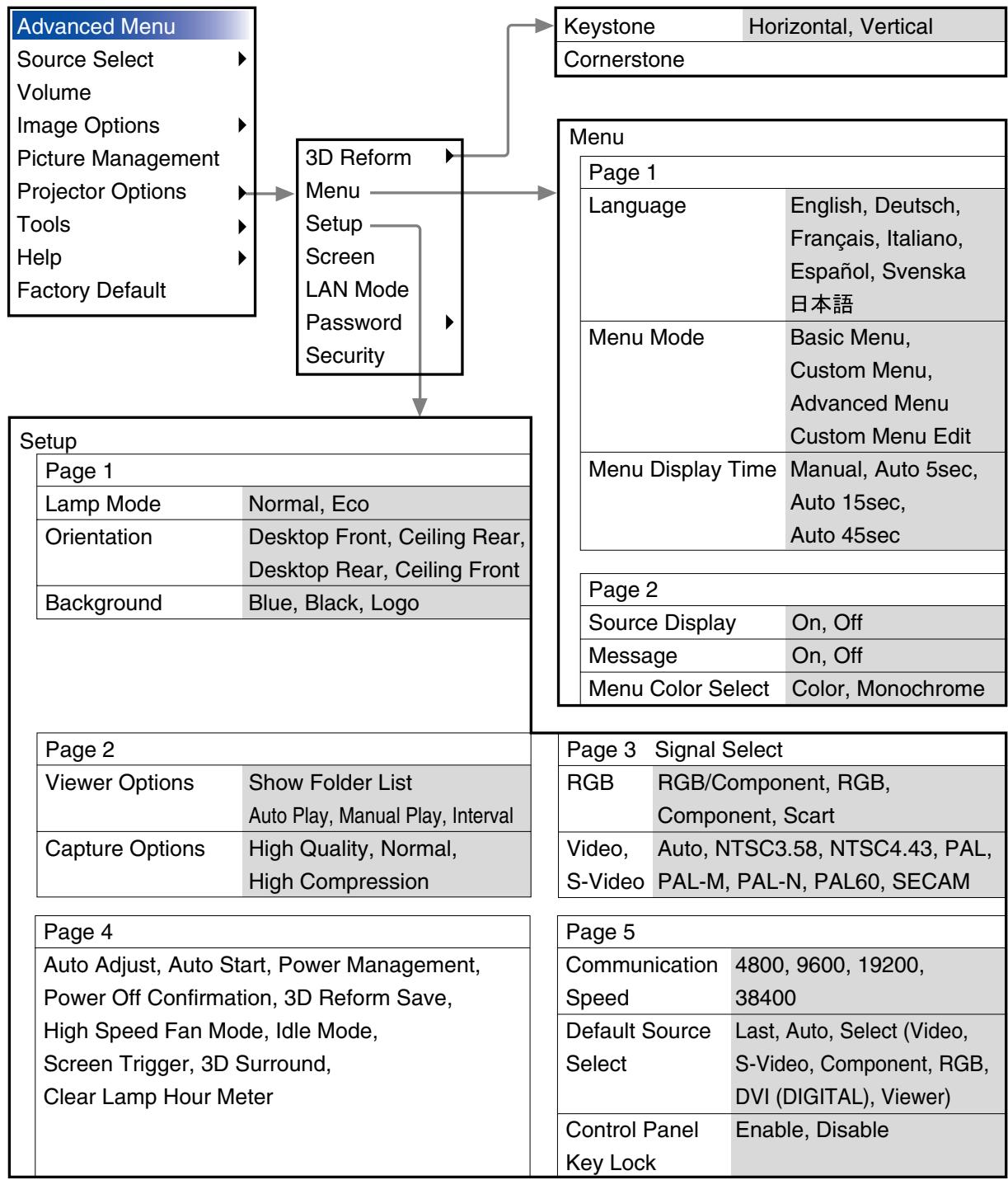
Menu [Page1] E-40
Selecting Menu Language/Selecting Menu Mode/Customizing the Menu/Selecting Menu Display Time
Menu [Page 2] E-40
Turning On / Off Source Display / Turning On / Off Message / Selecting Menu Color
Setup [Page 1] E-41
Setting Lamp Mode to Normal or Eco/Selecting Projector Orientation/ Selecting a Color or Logo for Background
Setup [Page 2] E-41
Setting Viewer Options/Selecting Capture Options
Setup [Page 3] E-41
Selecting Signal Format
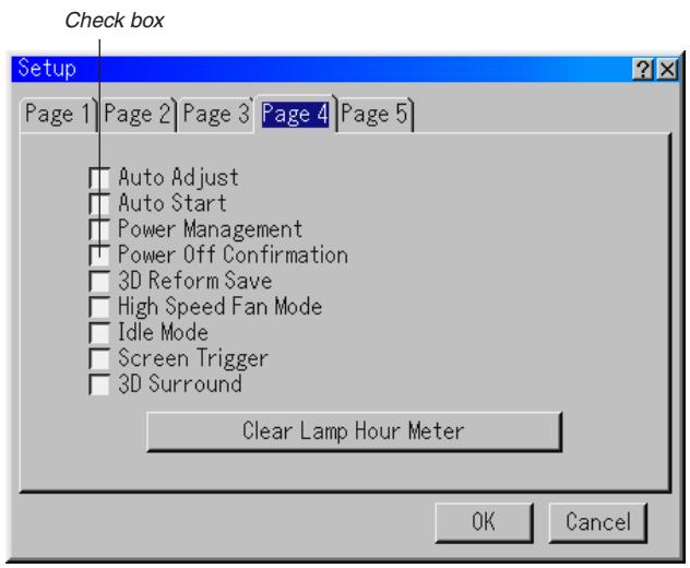
Setup [Page 4] E-41
Enabling Auto Adjust/Enabling Auto Start/Enabling Power Management/Enabling Power Off Confirmation/Enabling Horizontal and Vertical Keystone Correction Save/Enabling High Speed Fan Mode/Enabling Idle Mode/Enabling Screen Trigger/Enabling 3D Surround/Clearing Lamp Hour Meter
Setup [Page 5] E-42
Selecting Communication Speed/Selecting Default Source/Disabling the Cabinet Buttons
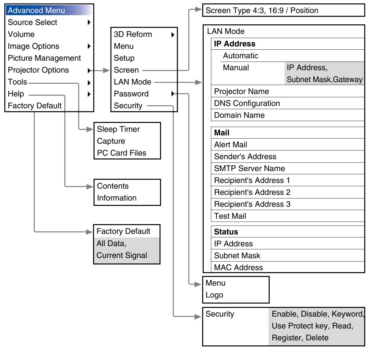
Selecting Aspect Ratio and Position for Screen E-43
Setting LAN Mode E-43
IP Address E-43
Mail E-44
Status E-44
Setting a Password E-45
Security E-45
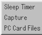
Tools E-47
Using Sleep Timer E-47
Using Capture E-47
Using PC Card Files E-47
Help E-47
Contents E-47
Information E-47
Returning to Factory Default E-47
MAINTENANCE E-48
Replacing the Lamp E-48
Cleaning E-49
Lens Protector E-49
TROUBLESHOOTING E-50
Power Indicator E-50
Status Indicator E-50
Lamp Indicator E-50
Common Problems & Solutions E-51
When using the Viewer function. E-51
SPECIFICATIONS E-52
APPENDIX E-53
Cabinet Dimensions E-53
Pin Assignments of D-Sub RGB Input Connector E-53
Compatible Input Signal List E-54
Compatible Input Signal List for DVI Signal (RGB only) E-55
PC Control Codes and Cable Connection E-56
PC Control Connector (DIN-8P) E-56
Using Software Keyboard E-56
Operation Using an HTTP Browser E-57
TravelCare Guide E-58
Introduction to the Projector
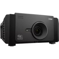
This section introduces you to your new HT1000 Projector and describes the features and controls.
Congratulations on Your Purchase of The HT1000 Projector
The HT1000 is our most sophisticated single chip DLPTM based projector for the commercial and residential entertainment user. With the HT1000 you will enjoy projecting images up to 200^ (measured diagonally) from your DVD player, VCR, satellite hookup, HDTV source, PC or Macintosh computer (desktop or notebook) and images from your digital camera. The HT1000 can be setup on a coffee table, tabletop, cart, bookshelf or permanently installed ^*1 . With an extensive input panel, quick connect guide and full function remote, you will be ready to immerse yourself in big screen enjoyment.
Features you'll enjoy on the HT1000:
- Phenomenal 3000:1 contrast ratio with a variable IRIS that allows you to fine-tune the image contrast
- 3D Reform technology for positioning the projector in off center locations in the room and still get aligned images
- NEC designed and developed SweetVision™ technology for enhanced images, more vibrant colors and blacks richer with detail
- Faroudja® DCDi™ video processing technology
- Ability to display 16:9 and 4:3 aspect ratio sources
HDTV, SDTV compatibility - 3D 10-bit video decoder for expanded black levels and adaptive gamma correction
- Digital photo viewer to display larger than life images from your digital cameras PC or compact flash card
Built in speakers with 3D sound for an integrated audio solution - Easy set up and operation
High performance long life lamp for low total operating costs - Eco-mode lamp technology for increased lamp life and energy savings
- Uncompromising display of video and data. Improves white level, color accuracy, dynamic range, and display of varying levels of black in an image.
- Sealed optics for reduced maintenance and better performance in dusty areas
- Wireless remote control operation
Network capable with a wired card for the ability to maintain and control your projector from your computer - Smart security settings for password protection, control panel lock and PC card protection key to help prevent unauthorized use
- Multiple video mode selections depending on your source.
Control the unit with a PC using the PC Control port. - NEC's exclusive Advanced AccuBlend intelligent pixel blending technology - an extremely accurate image compression technology - offers a crisp image with HTDV 1080p (1920 × 1080) resolution ^+2 .
Supports most IBM VGA, SVGA, XGA, SXGA (with Advanced AccuBlend)*², Macintosh, component signal (YCbCr/YPbPr) or any other RGB signals within a horizontal frequency range of 24 to 69 kHz and a vertical frequency range of 48 to 88 Hz. This includes NTSC, PAL, PAL-N, PAL-M, PAL60, SECAM and NTSC4.43 standard video signals.
NOTE: Composite video standards are as follows:
NTSC: U.S. TV standard for video in U.S. and Canada.
PAL: TV standard used in Western Europe.
PAL-N: TV standard used in Argentine, Paraguay and Uruguay.
PAL-M: TV standard used in Brazil.
PAL60: TV standard used for NTSC playback on PAL TVs.
SECAM: TV standard used in France and Eastern Europe.
NTSC4.43: TV standard used in Middle East countries.
- You can control the projector with a PC using the PC Control port and wired LAN.
- The contemporary cabinet design is light, compact, easy to carry.
*1 Do not attempt to mount the projector on a ceiling yourself.
The projector must be installed by qualified technicians in order to ensure proper operation and reduce the risk of bodily injury. In addition, the ceiling must be strong enough to support the projector and the installation must be in accordance with any local building codes. Please consult your dealer for more information.
*2 HDTV 1080p (1920×1080), HDTV 1080i (1920×1080) and HDTV 720p (1280×720) are displayed with NEC's Advanced AccuBlend.
Digital Light Processing, DLP, Digital Micromirror Device and DMD are trademarks of Texas Instruments.
The specifications are subject to change without notice.
Faroudja is a registered trademark of Faroudja Laboratories, Inc. DCDi is a trademark of Faroudja Laboratories, Inc.
All other trademarks are the property of their respective owners.
All specifications subject to change without notice.
Part Names of the Projector
Focus Ring (See page E-20)
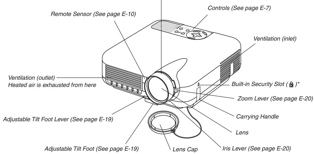
* This security slot supports the MicroSaver® Security System. MicroSaver® is a registered trademark of Kensington Microware Inc. The logo is trademarked and owned by Kensington Microware Inc.
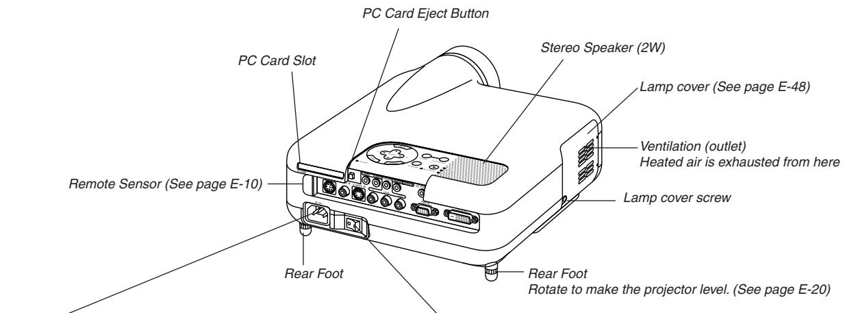
AC Input
Connect the supplied power cable's three-pin plug here, and plug the other end into an active wall outlet. (See page E-17)
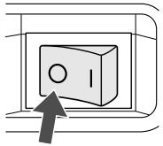
Main Power Switch
When you plug the supplied power cable into an active wall outlet and turn on the Main Power switch, the POWER indicator turns orange and the projector is in standby mode. (See page E-18)
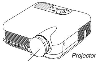
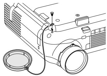
Attaching the lens cap
To attach the lens cap to the bottom with the supplied string and rivet:
- Thread the string through the hole on the lens cap and then tie a knot in the string.
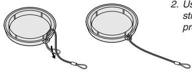
- Use the rivet to attach the string to the bottom of the projector.
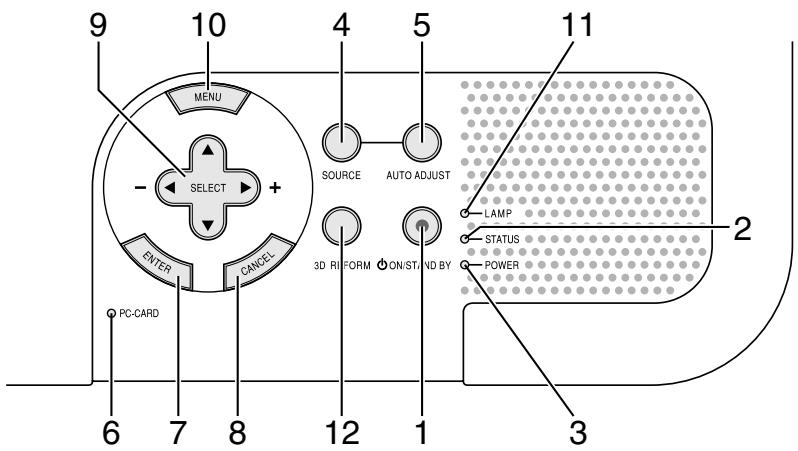
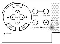
- POWER Button (ON / STAND BY) (♂)
Use this button to turn the power on and off when the main power is supplied and the projector is in standby mode.
NOTE: To turn on or off the projector, press and hold this button for a minimum of two seconds.
- STATUS Indicator
If this light blinks red rapidly, it indicates that an error has occurred, the lamp cover is not attached properly or the projector has overheated. If this light remains orange, it indicates that you have pressed a cabinet key while the Control Panel Key Lock is enabled. See the Status Indicator section on page E-50 for more details.
- POWER Indicator
When this indicator is green, the projector is on; when this indicator is orange, it is in standby or idle mode. See the Power Indicator section on page E-50 for more details.
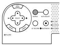
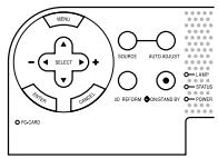
- SOURCE Button
Use this button to select a video source such as a VCR, DVD player, PC or Viewer (PC card).
Press and release this button quickly to display the Source List.
Each time this button is pressed for a minimum of ONE second the input source will change as follows:
Video S-Video Component RGB DVI (DIGITAL) Viewer Video ...
If no input signal is present, the input will be skipped.
- AUTO ADJUST Button
Use this button to adjust Position-H/V and Pixel Clock/Phase for an optimal picture. Some signals may not be displayed correctly or take time to switch between sources.
NOTE: This function may not be available depending upon the input signal.
- PC CARD Access Indicator
Lights while accessing a PC card.
- ENTER Button
Executes your menu selection and activates items selected from the menu.
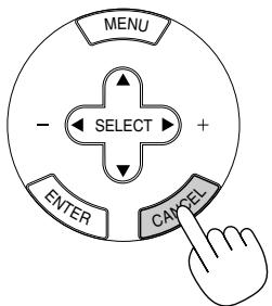
- CANCEL Button
Press this button to exit "Menu". Press this button to return the adjustments to the last condition while you are in the adjustment or setting menu.
- SELECT ▲▼▲▶ (+) (-) / Volume Buttons
: Use these buttons to select the menu of the item you wish to adjust. When no menus appear, these buttons work as a volume control.
Use these buttons to change the level of a selected menu item. A press of the button executes the selection. When the menus or the Viewer tool bar is not displayed, these buttons can be used to select a slide, or to move the cursor in Folder List or Slide List.
- MENU Button
Displays the menu.
- LAMP Indicator
If this light blinks red rapidly, it's warning you that the projection lamp has exceeded 1500 hours (up to 2000 hours in Eco mode) of service. After this light appears, replace the lamp as soon as possible. (See page E-48). If this is lit green continually, it indicates that the lamp mode is set to Eco. See the Lamp Indicator section on page E-50 for more details.
12.3D REFORM Button
Press this button to enter 3D Reform mode to correct the keystone (trapezoidal) distortion, and make the image square.
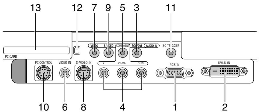
- RGB IN / Component Input Connector (Mini D-Sub 15 Pin) Connect your computer or other analog RGB equipment such as IBM compatible or Macintosh computers. Use the supplied RGB cable to connect to your computer. This also serves as a component input connector that allows you to connect a component video output of component equipment such as a DVD player. This connector also supports SCART output signal. See page E-16 for more details.
- DVI-D IN (DVI 24 Pin) This connector can be used to accept digital signal output from a computer or a setup box with a DVI connector. (HDCP compatible)
- RGB/DVI AUDIO IN Mini Jack (Stereo Mini) This is where you connect audio output from your computer connected to RGB IN or DVI-D IN.
- COMPONENT (Y, Cb/Pb, Cr/Pr) input Connectors (RCA)
Connect component video outputs (Y/Cb/Cr, Y/Pb/Pr) of the external equipment such as DVD player.
NOTE: These connectors accept component signal only. - COMPONENT AUDIO IN Mini Jack (Stereo Mini) This is where you connect audio output from your DVD player or component equipment connected to COMPONENT IN.
- VIDEO IN (RCA) Connect a VCR, DVD player or laser disc player here to project video.
7.VIDEO AUDIO IN Mini Jack (Stereo Mini) This is where you connect audio output from your VCR, DVD player or laser disc player connected to VIDEO IN. - S-VIDEO IN (Mini DIN 4 Pin) Connect a VCR, DVD player or laser disc player with S-Video output. NOTE: S-Video provides more vivid color and higher resolution than the traditional composite video format.
-
S-VIDEO AUDIO IN Mini Jack (Stereo Mini) This is where you connect audio output from your VCR, DVD player or laser disc player connected to S-VIDEO IN.
-
PC CONTROL Port (Mini DIN 8 Pin) Use this port to connect your PC to control your projector via a serial cable. This enables you to use your PC and serial communication protocol to control the projector. The NEC optional serial cable (CA03D) is required to use this port. If you are writing your own program, typical PC control codes are on page E-56. A cap is put on the port at the factory. Remove the cap when using the port.
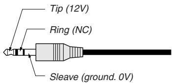
- SC TRIGGER Mini Jack
When the projector is powered ON the screen trigger output sends a high voltage trigger to the screen controller and the screen will go down.
When the projector is powered OFF the screen trigger stops sending a low voltage trigger to the screen controller and the screen will go up.
NOTE: To enable the SC.TRIGGER function, be sure to turn on "Screen Trigger" in "Page 4" of the Setup. See page E-42.
NOTE: Screen Controllers are supplied and supported by screen manufactures. This option is not included with the projector.
NOTE: Do not use this jack for anything other than intended use. Connecting an audio cable or equivalent to the SC. TRIGGER Mini Jack causes damage to this mini jack.
Stereo mini cable (not supplied)
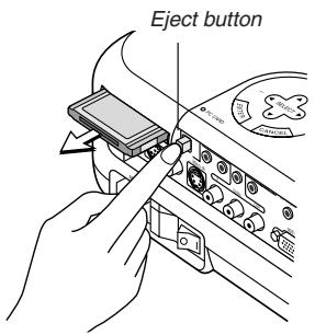
- PC CARD Eject Button Press to eject a PC card partially.
- PC CARD Slot Insert a PC card or commercially available wired LAN card here.
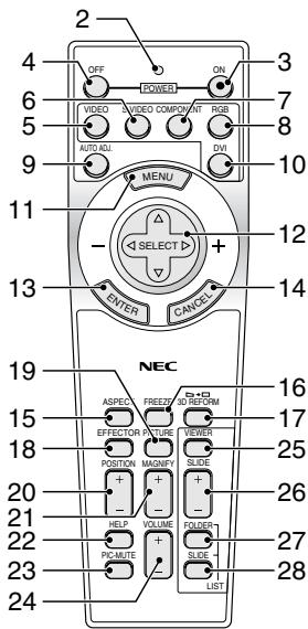
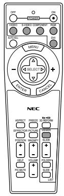
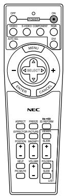
Part Names of the Remote Control
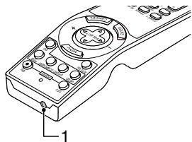
- Infrared Transmitter
Direct the remote control toward the remote sensor on the projector cabinet.
- LED
Flashes when any button is pressed.
- POWER ON Button
If the main power is applied, you can use this button to turn your projector on.
NOTE: To turn on the projector, press and hold the POWER ON button for a minimum of two seconds.
- POWER OFF Button
You can use this button to turn your projector off.
NOTE: To turn off the projector, press and hold the POWER OFF button for a minimum of two seconds.
5.VIDEO Button
Press this button to select an NTSC, PAL, PAL-N, PAL-M, PAL60, SECAM or NTSC4.43 compatible video source from a VCR, DVD player, or laser disc player.
- S-VIDEO Button
Press this button to select an S-Video source from a VCR, DVD player or laser disc player.
- COMPONENT Button
Press this button to select a video source from component equipment connected to your COMPONENT input.
- RGB Button
Press this button to select a video source from computer or component equipment connected to your RGB INPUT port.
- AUTO ADJ Button
Use this button to adjust an RGB source for an optimal picture. Some signals may not be displayed correctly or take time to be displayed. See page E-21.
NOTE: This function may not be available depending upon the input signal.
- DVI Button
Press this button to select a DVI digital signal from a computer or setup box.
- MENU Button
Displays the menu for various settings and adjustments.
- SELECT Button
: Use these buttons to select the menu of the item you wish to adjust.
Use these buttons to change the level of a selected menu item. A press of the button executes the selection. When the menus or the Viewer tool bar is not displayed, these buttons can be used to select a slide, or to move the cursor in Folder List or Slide List.
- ENTER Button
Executes your menu selection and activates items selected from the menu.
- CANCEL Button
Press this button to exit "Menu". Press this button to return the adjustments to the last condition while you are in the adjustment or setting menu.
- ASPECT Button
Press this button to display the Aspect Ratio select screen. See page E-36.
- FREEZE Button
This button will freeze a picture. Press again to resume motion.
17.3DREFORMButton
Press this button to enter 3D Reform to correct the keystone (trapezoidal) distortion, and make the image square. See page E-20.
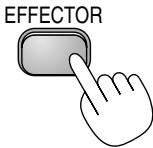
18.EFFECTORButton
Press this button to display the Sweet Vision setup screen. You can set options for the Sweet Vision feature in the Setup from the menu. See page E-23.
- PICTURE Button
Press this button to display the Picture Management window. See page E-38.
- POSITION Button
This button adjusts position of a zoomed image. See page E-23.
- MAGNIFY (+) (-) Button
Use this button to adjust the image size up to 400% . The image is magnified about the center of the screen. When the image is magnified, you can move the image by using the SELECT button. See page E-24.
- HELP Button
Provides the online help or the set information.
- PIC-MUTE Button
This button turns off the image and sound for a short period of time. Press again to restore the image and sound.
NOTE: When the menu is displayed, a press of this button mutes an image and sound without turning off the menu.
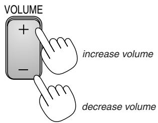
- VOLUME (+) (-) Button
Press (+) to increase the volume and (-) to decrease it.
- VIEWER Button
Press this button to select the Viewer source.
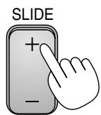
- SLIDE (+) (-) Button
Press (+) to select the next folder or slide and (-) to select the previous folder or slide. See page E-27.
- FOLDER LIST Button
Press this button to select Viewer source to display a list of folders included in a PC card. See page E-27.
28.SLIDE LIST Button
Press this button to select Viewer source to display a list of slides included in a PC card. See page E-27.
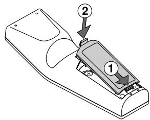
Battery Installation
- Press firmly and slide the battery cover off.
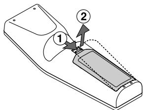
- Remove both old batteries and install new ones (AA). Ensure that you have the batteries' polarity (+/-) aligned correctly.
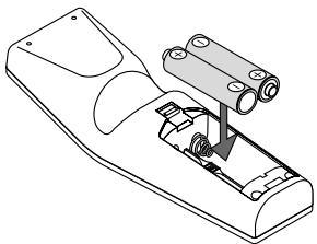
- Slip the cover back over the batteries until it snaps into place. Do not mix different types of batteries or new and old batteries.
Note on Remote Control Operation:
If you press and hold the SELECT button while installing new batteries, the remote control may fail to work properly.
Should this happen, remove the batteries and then install them again without touching the SELECT button.
Remote Control Precautions
- Handle the remote control carefully.
- If the remote control gets wet, wipe it dry immediately.
- Avoid excessive heat and humidity.
- If you will not be using the remote control for a long time, remove the batteries.
- Do not place the batteries upside down.
- Do not use new and old batteries together, or use different types of batteries together
Operating Range
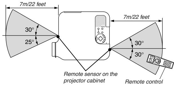
- The infrared signal operates by line-of-sight up to a distance of about 22 feet / 7 m and within a 55^ (Front) / 60^ (Rear) angle of the remote sensor on the projector cabinet.
- The projector will not respond if there are objects between the remote control and the sensor, or if strong light falls on the sensor. Weak batteries will also prevent the remote control from properly operating the projector.
INSTALLATION AND CONNECTIONS
This section describes how to set up your projector and how to connect video and audio sources.
Your projector is simple to set up and use. But before you get started, you must first:
1 Set up a screen and the projector.
2 Connect your video equipment to the projector. See page E-13 - 17.
3 Connect the supplied power cable. See page E-17.
NOTE: Ensure that the power cable and any other cables are disconnected before moving the projector. When moving the projector or when it is not in use, cover the lens with the lens cap.
Setting Up the Screen and the Projector
Selecting a Location
The further your projector is from the screen or wall, the larger the image. The minimum size the image can be is approximately 30^ (0.8 m) measured diagonally when the projector is roughly 4 feet (1.0 m) from the wall or screen. The largest the image can be is 200^ (5.08 m) when the projector is about 23 feet (7 m) from the wall or screen. Use the drawing below as a guide.
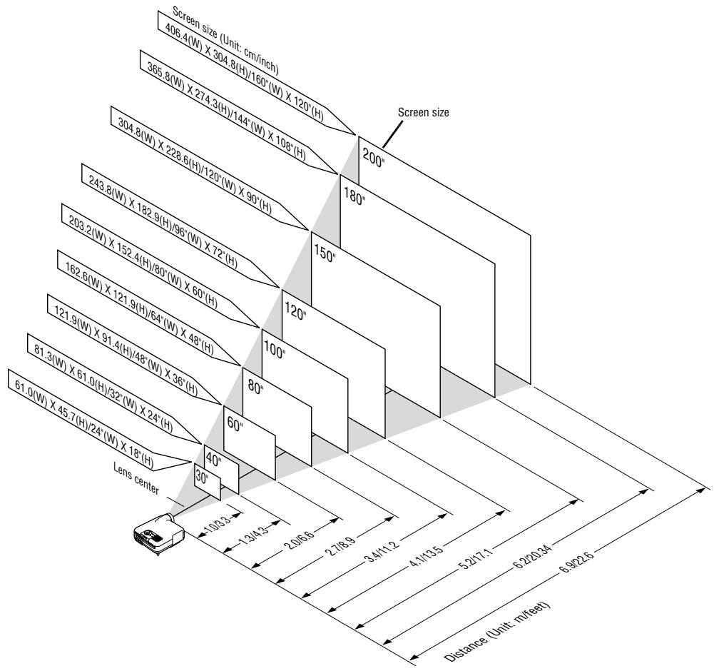
NOTE: The above shows the throw distance for 4:3 screen.
Throw Distance and Screen Size
The following shows the proper relative positions of the projector and screen. Refer to the table to determine the position of installation.
Distance Chart
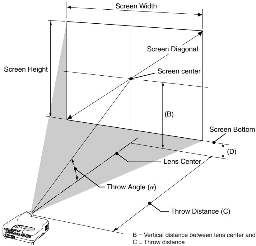
B = Vertical distance between lens center and screen center
C = Throw distance
D = Vertical distance between lens center and bottom of screen
= Throw angle
NOTE: Distances may vary +/-5%.
4:3
| Screen Size | B | C Wide – Tele | D | α Wide – Tele | ||
| Diagonal | Width | Height | ||||
| inch | inch | inch | inch | inch | inch | degree |
| 30 | 24 | 18 | 12.6 | 35.7 – 43.4 | 3.6 | 19.3 – 16.1 |
| 40 | 32 | 24 | 16.8 | 48.2 – 58.4 | 4.8 | 19.1 – 16.0 |
| 50 | 40 | 30 | 21.0 | 60.7 – 73.5 | 6.0 | 19.0 – 15.9 |
| 60 | 48 | 36 | 25.2 | 73.2 – 88.5 | 7.2 | 18.9 – 15.8 |
| 80 | 64 | 48 | 33.6 | 98.1 – 118.6 | 9.6 | 18.9 – 15.8 |
| 100 | 80 | 60 | 42.0 | 123.1 – 148.6 | 12.0 | 18.8 – 15.7 |
| 120 | 96 | 72 | 50.4 | 148.1 – 178.7 | 14.4 | 18.8 – 15.7 |
| 150 | 120 | 90 | 63.0 | 185.5 – 223.8 | 18.0 | 18.7 – 15.7 |
| 180 | 144 | 108 | 75.6 | 223.0 – 268.9 | 21.6 | 18.7 – 15.7 |
| 200 | 160 | 120 | 84.0 | 248.0 – 298.9 | 24.0 | 18.7 – 15.7 |
| Screen Size | B | C Wide – Tele | D | α Wide – Tele | ||
| Diagonal | Width | Height | ||||
| mm | mm | mm | mm | mm | mm | degree |
| 762.0 | 609.6 | 457.2 | 319.8 | 907 – 1102 | 91.2 | 19.3 – 16.1 |
| 1016.0 | 812.8 | 609.6 | 426.5 | 1224 – 1484 | 121.7 | 19.1 – 16.0 |
| 1270.0 | 1016.0 | 762.0 | 533.3 | 1541 – 1866 | 152.3 | 19.0 – 15.9 |
| 1524.0 | 1219.2 | 914.4 | 640.0 | 1858 – 2248 | 182.8 | 18.9 – 15.8 |
| 2032.0 | 1625.6 | 1219.2 | 853.4 | 2493 – 3011 | 243.8 | 18.9 – 15.8 |
| 2540.0 | 2032.0 | 1524.0 | 1066.9 | 3127 – 3775 | 304.9 | 18.8 – 15.7 |
| 3048.0 | 2438.4 | 1828.8 | 1280.4 | 3761 – 4539 | 366.0 | 18.8 – 15.7 |
| 3810.0 | 3048.0 | 2286.0 | 1600.6 | 4713 – 5684 | 457.6 | 18.7 – 15.7 |
| 4572.0 | 3657.6 | 2743.2 | 1920.8 | 5664 – 6829 | 549.2 | 18.7 – 15.7 |
| 5080.0 | 4064.0 | 3048.0 | 2134.3 | 6298 – 7593 | 610.3 | 18.7 – 15.7 |
NOTE: A 16:9 image is supported within the limits of the above values.
WARNING
- Installing your projector on the ceiling must be done by a qualified technician. Contact your NEC dealer for more information.
- Do not attempt to install the projector yourself.
- Only use your projector on a solid, level surface. If the projector falls to the ground, you can be injured and the projector severely damaged.
- Do not use the projector where temperatures vary greatly. The projector must be used at temperatures between 41^ ( 5^ ) and 95^ ( 35^ ).
- Do not expose the projector to moisture, dust, or smoke. This will harm the screen image.
- Ensure that you have adequate ventilation around your projector so heat can dissipate. Do not cover the vents on the side or the front of the projector.
Reflecting the Image
Using a mirror to reflect your projector's image enables you to enjoy a much larger image. Contact your NEC dealer if you need a mirror. If you're using a mirror and your image is inverted, use the MENU and SELECT buttons on your projector cabinet or buttons on your remote control to correct the orientation. (See page E-41.)
Making Connections
Wiring Diagram
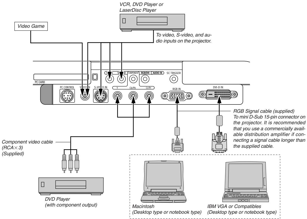
NOTE: When using with a notebook PC, be sure to connect between the projector and the notebook PC before turning on the power to the notebook PC. In most cases signal cannot be output from RGB output unless the notebook PC is turned on after connecting with the projector.
If the screen goes blank while using your remote control, it may be the result of the computer's screen-saver or power management software.
If you accidentally hit the POWER button on the remote control, wait 90 seconds and then press the POWER button again to resume.

Use the supplied composite video cable to connect your VCR or laser disc player to your projector.
To make these connections, simply:
- Turn off the power to the projector and VCR or laser disc player.
- Connect one end of the composite video cable to the video output connector on the back of your VCR or laser disc player, connect the other end to the Video input on your projector. Use an audio cable (not supplied) to connect the audio from your VCR or laser disc player to your audio equipment (if your VCR or laser disc player has this capability). Be careful to keep your right and left channel connections correct for stereo sound.
- Turn on the projector and the VCR or laser disc player.
NOTE: Refer to your VCR or laser disc player owner's manual for more information about your equipment's video output requirements.
NOTE: An image may not be displayed correctly when a Video or S-Video source is played back in fast-forward or fast-rewind via a scan converter.
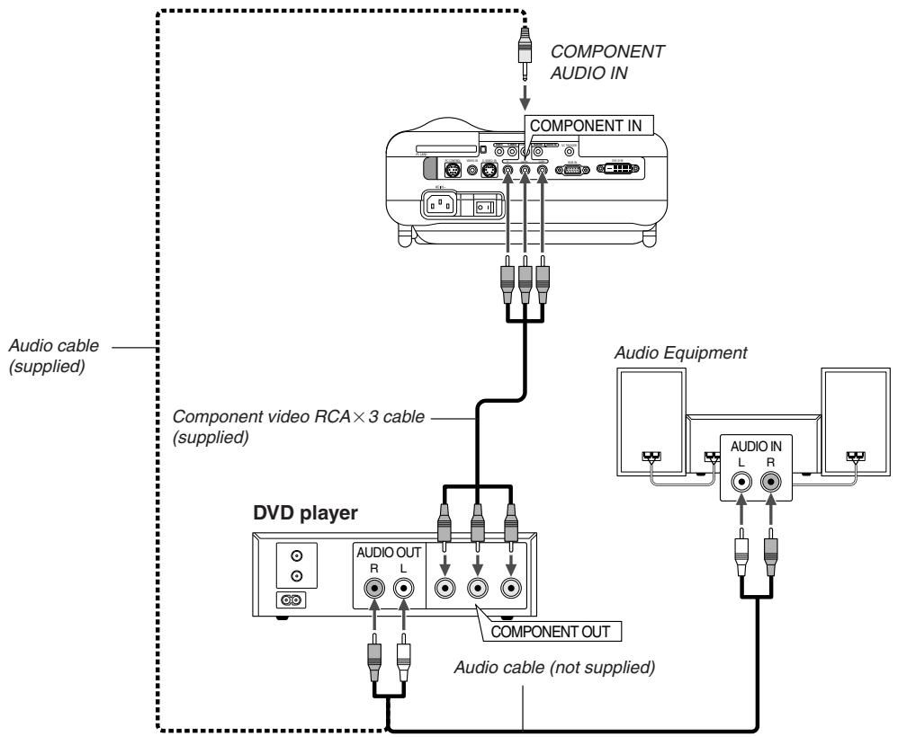
You can connect your projector to a DVD player with component output or Video output. To do so, simply:
- Turn off the power to your projector and DVD player.
- If your DVD player has the component video (Y,Cb,Cr) output, use the supplied component video cable (RCA× 3) to connect your DVD player to the COMPONENT IN connectors on the projector.
For a DVD player without component video (Y,Cb,Cr) output, use common RCA cables (not provided) to connect a composite VIDEO output of the DVD player to the Video Input of the projector.
Use an audio cable (not supplied) to connect the audio from your VCR or laser disc player to your audio equipment (if your VCR or laser disc player has this capability). Be careful to keep your right and left channel connections correct for stereo sound.
- Turn on the projector and DVD player.
NOTE: Refer to your DVD player's owner's manual for more information about your DVD player's video output requirements.
Connecting Your PC or Macintosh Computer
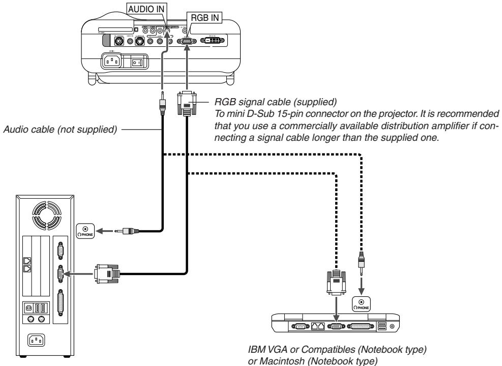
NOTE: For older Macintosh, use a commercially available pin adapter (not supplied) to connect to your Mac's video port.
IBM VGA or Compatible (Desktop type) or Macintosh (Desktop type)
Connecting your PC or Macintosh computer to your projector will enable you to project your computer's screen image for an impressive presentation.
To connect to a PC or Macintosh, simply:
- Turn off the power to your projector and computer.
- Use the supplied signal cable to connect your PC or Macintosh to the projector.
- Turn on the projector and the computer.
- If the projector goes blank after a period of inactivity, it may be caused by a screen saver installed on the computer you've connected to the projector.
NOTE: The HT1000 is not compatible with video decoded outputs of NEC ISS-6020 and ISS-6010.
For European model only
To connect SCART output (RGB)
Before connections: The supplied SCART adapter (ADP-SC1) and a commercially available SCART cable are required for this connection.
NOTE: Audio signal is not available for this connection.
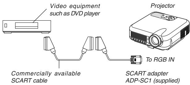
- Turn off the power to the projector and your video equipment.
- Use the supplied SCART adapter and a commercially available SCART cable to connect the RGB input of your projector and a SCART output (RGB) of your video equipment.
- Turn on the power to the projector and your video equipment.
- Use the RGB button on the remote control to select the RGB input.
- Press the MENU button on the remote control to display the menu.
- From the Advanced menu, select [Projector Options] [Setup] [Page 3] [Signal Select RGB] [Scart]. SCART is a standard European audio-visual connector for TVs, VCRs and DVD players. It is also referred to as Euro-connector.
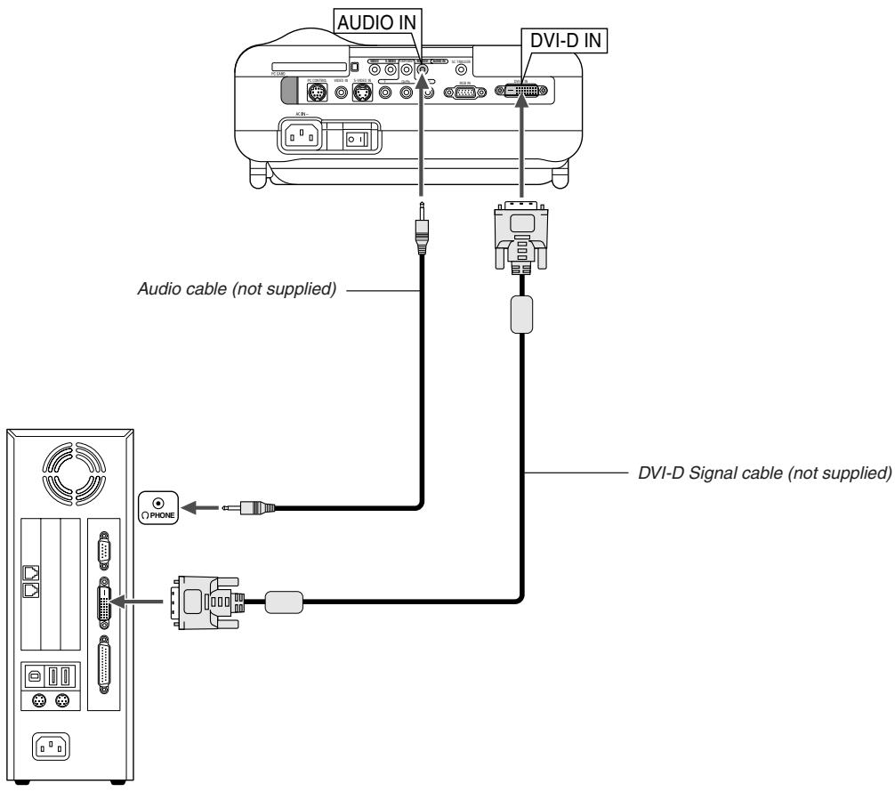
To project a DVI digital signal, be sure to connect the PC and the projector using a DVI-D signal cable (not supplied) before turning on your PC or projector. Turn on the projector first and select DVI (DIGITAL) from the source menu before turning on your PC.
Failure to do so may not activate the digital output of the graphics card resulting in no picture being displayed. Should this happen, restart your PC. Do not disconnect the DVI-D signal cable while the projector is running. If the signal cable has been disconnected and then re-connected, an image may not be correctly displayed. Should this happen, restart your PC.
NOTE:
- Use the DVI-D cable compliant with DDWG (Digital Display Working Group) DVI (Digital Visual Interface) revision 1.0 standard. The DVI-D cable should be within 5 m (196') long.
- The DVI (DIGITAL) connector accepts VGA (640x480), SVGA (800x600), XGA (1024x768) and HDTV 1080p, 1080i, 720p, 750p, 480p, 480i, 525p, 576p and 625p.
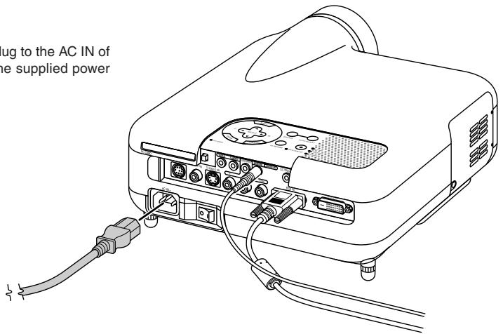
Connecting the Supplied Power Cable
Connect the supplied power cable to the projector.
First connect the supplied power cable's three-pin plug to the AC IN of the projector, and then connect the other plug of the supplied power cable in the wall outlet.
PROJECTING AN IMAGE (BASIC OPERATION)
This section describes how to turn on the projector and to project a picture onto the screen.
Turning on the Projector
NOTE:
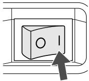
- When plugging in or unplugging the supplied power cable, make sure that the main power switch is pushed to the off[O] position. Failure to do so may cause damage to the projector.
- The projector has two power switches: main power switch and POWER button (POWER ON and OFF on the remote control)
- The projector has a feature to prevent itself from being used by unauthorized individuals. To use this feature, register your PC card as a protect key. See "Security" on page E-45 for more details.
To turn on the main power to the projector, press the Main Power switch to the ON position (1).
Before you turn on your projector, ensure that the computer or video source is turned on and that your lens cap is removed.
Only after you press the ON/STAND BY button on the projector cabinet or POWER ON button on the remote control for a minimum of 2 seconds will the power indicator turn to green and the projector become ready to use.
Note on Startup screen (Menu Language Select screen)
When you first turn on the projector, you will get the Startup screen. This screen gives you the opportunity to select one of the seven menu languages: English, German, French, Italian, Spanish, Swedish and Japanese.
To select a menu language, follow these steps:
- Use the SELECT or button to select one of the seven languages for the menu.

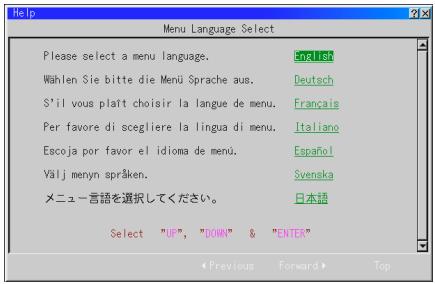
- Press the ENTER button to execute the selection.
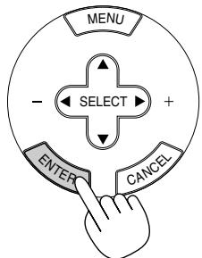
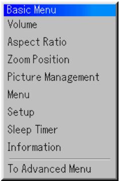
- The Basic menu will be displayed in the language you have selected.
To close the menu, press the CANCEL button.
After this has been done, you can proceed to the advanced menu operation.
If you want, you can select the menu language later. See "Language" on page E-40.
NOTE: To turn the projector on by plugging in the power cable, first turn on the Main Power switch to ON and use the menu and enable the 'Auto Start' feature. (See page E-41.) Immediately after turning on the projector, screen flicker may occur. This is not a fault. Wait 3 to 5 minutes until the lamp lighting is stabilized.
When the Lamp mode is set to Eco, the Lamp indicator will light green. If one of the following things happens, the projector will not turn on.
- If the internal temperature of the projector is too high, the projector detects abnormal high temperature. In this condition the projector will not turn on to protect the internal system. If this happens, wait for the projector's internal components to cool down.
- When the lamp reaches its end of usable life, the projector will not turn on. If this happens, replace the lamp.
- If the lamp fails to light, and if the STATUS indicator flashes on and off in a cycle of six times, wait a full minute and then turn on the power.
Selecting a Source
Selecting the computer or video source
Using the Remote Control
Press any one of the VIDEO, S-VIDEO, COMPONENT, RGB, DVI or VIEWER buttons.
NOTE: If no input signal is available, the projector will display a blue background (factory preset).
Selecting from Source List
Source List
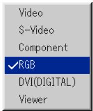
Press and quickly release the SOURCE button on the projector cabinet to display the Source list. Each time the SOURCE button is pressed, the input source will change as follows: "Video" (VCR, or laser disc player), S-Video", "Component" (DVD player), "RGB" or "DVI(DIGITAL)" (computer) or "Viewer" (slides on a PC card).
To display the selected source, press the ENTER button.
Detecting the Signal Automatically
Press and hold the SOURCE button for a minimum of 1 second, the projector will search for the next available input source. Each time you press and hold the SOURCE button, the input source will change as follows:
Video S-Video Component RGB DVI(DIGITAL) Viewer
If no input signal is present, the input will be skipped. When the input source you wish to project is displayed, release the button. Press the ENTER button.
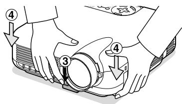
Adjusting the Picture Size and Position
Place your projector on a flat level surface and ensure that the projector is square to the screen.
Lift the front edge of the projector to center the image vertically.
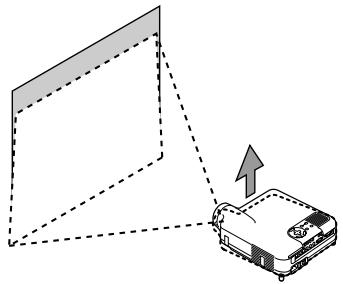
Move the projector left to center the image horizontally on the screen.
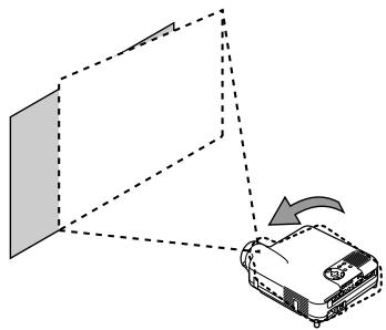
- If the projected image does not appear square to the screen then use the 3D Reform feature for proper adjustment. See page E-20.
Adjust the Tilt Foot
- Lift the front edge of the projector.
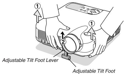
- Push up the Adjustable Tilt Foot Lever on the front of the projector to extend the adjustable tilt foot (maximum height).
- Push down the Adjustable Tilt Foot Lever.
- Lower the front of the projector to the desired height and release the Adjustable Tilt Foot Lever to lock the Adjustable tilt foot. There is approximately 7 degrees of up and down adjustment for the front of the projector.
Adjusting Screen Position
See "Selecting Aspect Ratio and Position for Screen" on page E-43.
The rear foot height can be changed. Rotate the rear foot to the desired height, but the vertical distance from the bottom to the desk or floor should be 1'' (25 mm) to make the projector horizontal on the flat surface.

CAUTION:
Do not use the tilt-foot for purposes other than originally intended. Misuses such as gripping the tilt-foot or hanging on the wall can cause damage to the projector.
Zoom
Use the Zoom lever to fine adjust the image size on the screen
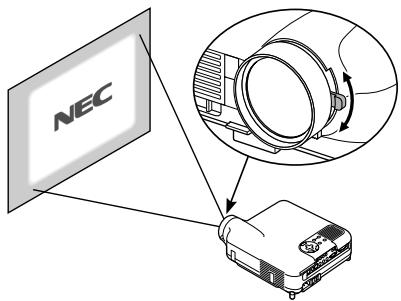
Focus
Use the Focus ring to obtain the best focus.

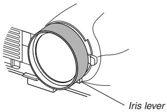
Iris
Use the Iris lever underneath the lens to adjust the brightness and the contrast optically.
Correcting the Horizontal and Vertical Keystone Distortion (3D Reform)
Use the 3D Reform feature to correct keystone (trapezoidal) distortion to make the top or bottom and the left or right side of the screen longer or shorter so that the projected image is rectangular.
Two options are available for correcting procedures.
You can save adjustment settings by using the 3D Reform Save option on Setup (See page E-42).
Keystone
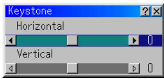
- Press the SELECT button to adjust the horizontal keystone.
- Press the SELECT button to select "Vertical".
- Press the SELECT button to adjust the vertical keystone.
- After completing, press the ENTER button. This will return to the menu screen.
Cornerstone
- Project an image so that the screen is smaller than the area of the raster.
- Pick up any one of the corners and align the corner of the screen with the one of the image.
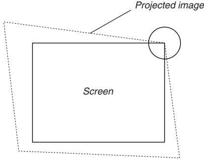
(The drawing shows the upper right corner.)
- Press the 3D REFORM button on the remote control.
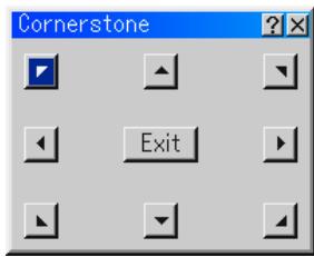
The CORNERSTONE adjustment screen is displayed.
NOTE: Press the 3D REFORM button to toggle between "Cornerstone" and "Keystone."
- Use the SELECT button to select one icon which points in the direction you wish to move the projected image frame.
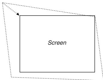
- Press the ENTER button.
- Use the SELECT button to move the projected image frame as shown on the example.
- Press the ENTER button.
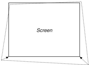
- Use the SELECT button to select another icon which points in the direction.
On the Cornerstone adjustment screen, select "Exit" and then "OK", or press the CANCEL button on the remote control.
The confirmation screen is displayed.
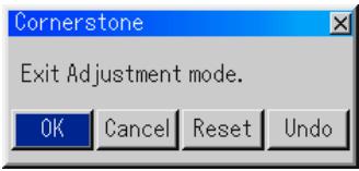
- Press the SELECT or button to highlight the [OK] and press the ENTER button.
This completes the keystone correction.
Selecting "Cancel" will return to the adjustment screen without saving changes (Step 3).
Selecting "Reset" will return to the factory default.
Selecting "Undo" will exit without saving changes.
NOTE: To return the 3D Reform correction setting values to the factory default, press and hold the 3D REFORM button for a minimum of 2 seconds.
NOTE: During 3D Reform adjustment, "Aspect Ratio" and "Screen" may not be available. Should this happen, first reset the 3D Reform data and then do each setting. Second repeat the 3D Reform adjustment. Changing Aspect Ratio and/or Screen setting can limit 3D Reform in its adjustable range.
The adjustable ranges for 3D Reform are as follows:
Horizontal Max ± 25^ approx. Vertical Max ± 40^ approx.
- The following are conditions at the above maximum angle when all of the following are met
- Image is projected in Wide (Zoom lever)
- Resolution is XGA
Higher resolution than XGA limits 3D Reform in its adjustable range.
- Menu items should be set as follows:
Aspect Ratio . Normal
Screen Type 4:3
Horizontal and Vertical are adjusted separately.
A combination of both adjustments limits 3D Reform in its adjustable range.
- When "Stadium" is selected in Aspect Ratio, "Cornerstone" and "Horizontal Keystone" are not available.
Optimizing RGB Picture Automatically
Adjusting the Image Using Auto Adjust
Optimizing RGB image automatically
Press the Auto Adjust button to optimize an RGB image automatically.
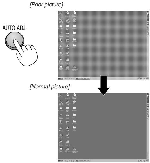
Press the Auto Adjust button to fine-tune the computer image or to remove any vertical banding that might appear and to reduce video noise, dot interference or cross talk (this is evident when part of your image appears to be shimmering). This function adjusts the clock frequencies that eliminate the horizontal banding in the image. This function also adjusts the clock phase to reduce video noise, dot interference or cross talk. (This is evident when part of your image appears to be shimmering.)
This adjustment may be necessary when you connect your computer for the first time.
NOTE:
- Some signals may not be displayed correctly or take time.
- The Auto Adjust function does not work for component and video signal.
- If the Auto Adjust operation cannot optimize the RGB signal, try to adjust Clock and Phase manually. See page E-38.
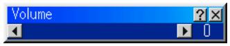
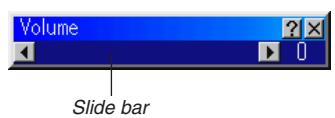
Turning Up or Down Volume
Sound level from the speaker on the projector can be adjusted.
Volume bar
Turning off the Projector
To turn off the projector:
First press the POWER (ON/STAND BY) button on the projector cabinet or the POWER OFF button on the remote control for a minimum of two seconds. The power indicator will glow orange. After the projector turns off, the cooling fans keep operating for 90 seconds (Cooling-off time).
Second, turn off the Main Power switch. The power indicator will go out. Last unplug the power cable.
CAUTION
Do not unplug the power cable from the wall outlet or do not turn off the main power under any one of the following circumstances. Doing so can cause damage to the projector:
While the Hour Glass icon appears.
While the message "Please wait a moment." appears. This message will be displayed after the projector is turned off.
- While the cooling fans are running. (The cooling fans continue to work for 90 seconds after the projector is turned off).
- While accessing a PC card. (The PC Card Access indicator lights.)
CONVENIENT FEATURES
Using Sweet Vision function Button
Press the EFFECTOR button to display the Sweet Vision set screen. You can set options for the Sweet Vision feature in the Setup from the menu.
NOTE: This button works only for "User" in the Picture Management. Even if "User" is selected in the Picture Management, this button may not work depending on the signals or settings.
Using Zoom Position
The POSITION button adjusts the position of a zoomed image.
When "4:3" is selected in Screen Type:
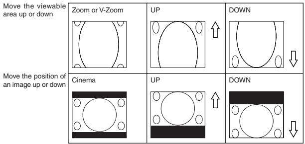
When "16:9" is selected in Screen Type:
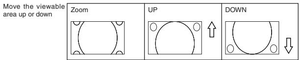
Table of Availability for Zoom Position
For PC, DVD Progressive, 480p, 480i, 576p, 576i
| Screen Type | Aspect Ratio | |||||
| Normal | Full | Zoom | Cinema | V-Zoom | Stadium | |
| 4:3 | Not available | Available | Available | Available | ||
| 16:9 | Not available | Not available | Available | Not available | ||
For 720p, 1080i, 1080p
| Screen Type | Aspect Ratio | |||||
| Normal | Full | Zoom | Cinema | V-Zoom | Stadium | |
| 4:3 | Available | Not available | Available | Not available | ||
| 16:9 | Not available | |||||
Turning Off the Image and Sound
Press the Picture Mute button to turn off the image and sound for a short period of time. Press again to restore the image and sound.

Freezing a Picture
Press the Freeze button to freeze a picture. Press again to resume motion.

Enlarging and Moving a Picture
You can enlarge the area you want up to 400 percent.
To do so:
To enlarge the image:
- Press the MAGNIFY (+) button.

- Press the MAGNIFY(-) button to return to its original size.

To enlarge the image:
Use the SELECT button to move the enlarged portion.
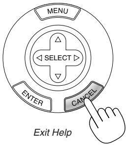
Getting the On-line Help
You get the contents about Help.

Display Help
Changing Background Logo
You can change the default background logo using the PC Card Files feature.
NOTE: File size must be 256KB or less. Other file formats than JPEG and BMP are not available.
- From the menu, select [Tools] [PC Card Files] to display a list of all the files stored in the PC card so that you can select a file you want to use as a background logo.
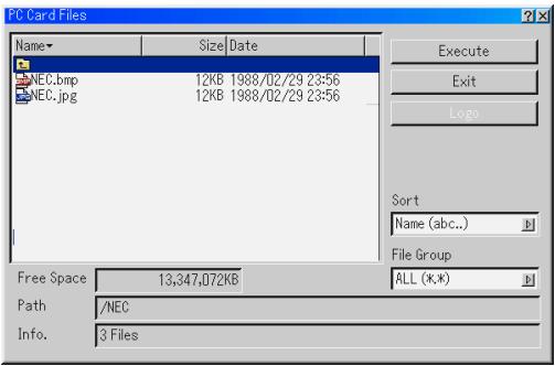
- The Logo button allows you to select a background logo from graphic files on a PC card and change to it as the background logo.
- Use the SELECT or button to select a JPEG or BMP file for your background logo.
- Use the SELECT and then button to select "Logo".
- Press the ENTER on the remote control or the cabinet. You will get the confirmation dialog box.
- Select "OK" and press the ENTER button. This completes changing a logo for the background.
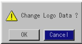
- Once you have changed the background from the NEC logo to another, you cannot return the logo to background even by using Factory Default. To do so, repeat the above steps.
USING THE VIEWER
Making the Most out of the Viewer Function
Features
You can view graphic data, capture, and play images on the projector. A PC card is used to view presentation data prepared on the computer and to capture and play images projected with the projector.
The Viewer feature allows you to view slides stored on a PC memory card (referred to as PC card in this manual) on the projector. Even if no computer is available, presentations can be conducted simply with the projector. This feature is convenient for holding presentations at meetings and in offices, as well as for playing images taken on digital cameras.
Easy to use
Viewer can be started immediately simply by inserting a PC card (not supplied)
Easy slide switching
Remote control operation
- Jumping to list of slides or any specific slide
High quality images
High resolution up to 1024 x 768 dots
24-bit full color playback
Viewing of digital camera images
Inserting and Removing a PC Card
Inserting the PC Card
- Hold the PC card horizontally and insert it slowly into card slot with its top facing up.
- The eject button pops out once the PC card is fully inserted. Check that the PC card is fully inserted.
NOTE: Do not try to force the PC card into the slot.
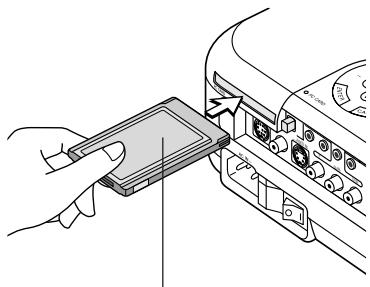
PC card (not supplied)
Removing the PC Card
Press the eject button. The PC card pops out a little. Grasp the edges of the PC card and pull it out.
NOTE: Do not eject the PC card while its data is being accessed.
Direction for Inserting the PC Card
The PC card has a top and bottom and must be inserted into the PC card slot in a specific direction. It cannot be inserted backwards or upside-down. Attempting to force it into the slot in the wrong direction may break the internal pin and damage the card slot. Refer to the PC card's operating instructions for the proper direction of insertion.
PC Card Type
The PC Card slot accepts PCMCIA Type II only.
Operating the Viewer Function from the Projection (playback)
This section describes the operation for showing slides created using the Viewer function with the projector. It is also possible to make slides directly from the images projected with the projector.
Projecting slides (Viewer)
- Insert a PC card into the PC card slot.
Insert the PC card with the side with the insertion direction arrow on the top.
- Press the eject button to eject the card.
- Select the "Viewer" from the Source Select menu.
- Project slides.
Checking "Show Folder List", means that selecting Viewer input displays a list of the folders in the PC card and if "Auto Play" is checked the projector automatically starts to play slides at the first slide of the folder you have selected.
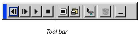
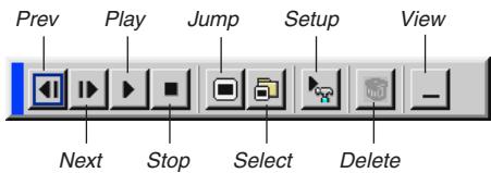
A tool bar will appear when you press the MENU button on the remote control or the projector cabinet.
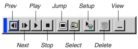
The tool bar includes the following buttons:
Prev....... Returns to the previous slide or folder. Or this lets you play slides back in reverse.
Next........................................................... Advances to the next slide or folder. Or this lets you play slides back.
Play ....... Plays back automatically or manually depending on the setting on Viewer Options of the menu. This allows you to move on to the next slide when "Manual Play" is selected.
Stop...... This allows you to stop Auto Play while you are playing back and to resume playing from the selected slide or folder when "Auto Play" is selected.
Jump ....... Displays a list of slides while you are playing back.
Select ....... Displays a list of folders while you are playing back.
Setup....... Displays the Viewer Options dialog box on Page 2 of the Setup dialog box.
Delete....... deletes a captured slide(s) or all the captured slides in the Capture - specific folder.
View ......... Hides the tool bar while you are playing back. Pressing the MENU button shows it again.
NOTE: If no memory card is inserted in the PC CARD slot, there is no signal, and a black, blue or logo background is displayed, depending on the setting. Playback is stopped when SLIDE +/- button on the remote control or button on the cabinet is pressed in Auto Play mode.
Up to 12 indexes can be displayed on the list of folders. The folder in the right bottom is always a folder exclusively for captured images, but is only displayed when images have been captured.
When the tool bar is not displayed:
Press the FOLDER LIST button or the SLIDE LIST button on the remote control to display folders or from a PC card in the projector's PC Card slot.

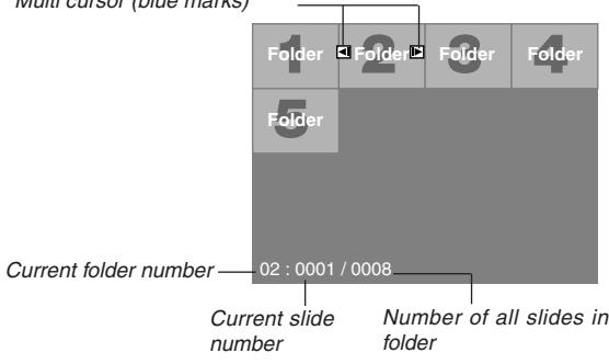
Multi cursor (blue marks)
Use the SLIDE + / - button to advance to the next folder or return to the previous folder.

Use the SLIDE +/- button to advance to the next slide or return to the previous slide.
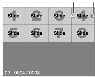
Slide(Table) cursor (green marks)
NOTE: You can also use the and button on the remote control to select folders or slides.
Auto Play Mode
If the "Auto Play" option is selected in "Viewer Options" of the menu, any given slide will start to play automatically.
You can also specify Auto Play Interval between 5 and 300 seconds.
Switching to Slides Directly from Other Input Modes
With this function it is possible to switch directly to a slide when the picture of a VCR or computer is being projected.
Example: When conducting presentations using a combination of slides and moving pictures from a VCR, etc., it is possible to switch from a Viewer slide to the video picture then back to the Viewer slide simply by using the Viewer button.
NOTE: Even if you switch the current Viewer source to another source, the current slide is retained. When you return back to the Viewer, you will get the slide that has been retained.
Viewing Digital Images
Digital images can be played with the Viewer if the following conditions are met:
- If the image can be stored on an MS-DOS format PC card
- If the image can be stored in a format supported by the Viewer. With the Viewer, images on the card are searched for in directories and images in JPEG or BMP format are recognized as slides. Searchable directories are directories within two steps from the root directory, and searchable images are images within the first 12 files in the directory. Only file and slide switching are possible.
NOTE: The maximum number of images recognized as slides within one directory is 128.
Storing Images Displayed on the Projector on the PC card (Capture)
The Capture features allows you to capture an image from a source that is currently being displayed. The image is saved as JPEG in the PC card. When you select Capture from the menu, you will get a tool bar. You can capture an image directly using the tool bar when the menu is not displayed.
NOTE:
- Signals from DVI input are not possible to be captured.
- Unless a PC card is inserted into the PC Card slot of the projector, the Capture feature is not available.
- The "Card Error" display means that the free space of the PC card is insufficient for saving images. Make more space available on the card by erasing unwanted images with your PC. The number of images that can be captured depends on the size of the PC card.
- Be sure not to turn off the power or remove the PC card while capturing an image. Doing so could cause a loss of the data in the PC card or damage to the card itself.
Preparations:
Insert the PC card into the card slot.
Insert the PC card so that the end with the insertion direction arrow on the top goes in first.
-
Press the eject button to eject the card.
-
Project the image you wish to store on the projector.
- Select the "Capture" from the Tools menu.
- A tool bar will appear.
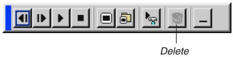
The tool bar includes the following buttons:
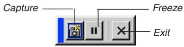
Capture ...... Captures an image and save it as a JPEG file in a PC card.
Freeze .... Freezes and unfreezes images.
Exit Exits the Capture function. Another option to exit the Capture function is to press MENU or CANCEL button on the remote control or projector cabinet.
NOTE:
You can compress a captured file (JPEG) using the Capture Options in the Setup dialog. See page E-41.
Captured images with higher resolution than the projector's native resolution cannot be displayed correctly.
- File size of the captured image varies depending on the resolution of an input signal.
- An hourglass indicating that an image is being captured appears on the projector's display. Do not eject the PC card or turn off the projector's power while this icon is displayed. Doing so will damage the PC card data. If the PC card data is damaged, use a computer to repair the data.
- Up to 12 indexes can be displayed on the list of folders. The folder in the right bottom is always a folder exclusively for captured images, but is only displayed when images have been captured.
Deleting Captured Images
Using the Delete button on the tool bar for Viewer can delete captured images.
To delete captured images:
- Select Viewer and display a folder list of captured images.
- Use button to select the Capture folder [Cap] in the right bottom of the screen.
- Press the MENU button to display the tool bar.
- Use the or button to select the Delete icon and press the ENTER button.
Using the PC Card Files Fucntion (PC Card Files)
The PC Card Files function allows you to display a list of all the files stored in the PC card so that you can select a file you want to display. You can also sort files by file name or date, or display the file. Although a list of all the files in the PC card is displayed, you can view files in idx, text, HTML, JPEG and BMP format only. Selecting BMP and JPEG files automatically switches to the Viewer source. See also page E-35.
NOTE: This option is not available for selection unless a PC card is inserted properly.
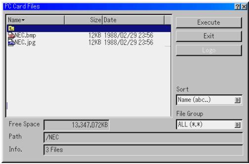
Selecting "Execute" displays the file you selected.
When you select a JPEG or BMP file and press the ENTER button on the remote or the cabinet, or "Execute" on the above, you will get a toolbar. This toolbar is used to return to the PC Card Files screen.
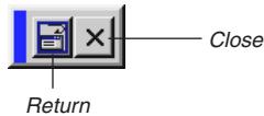
Return ......... Returns to the PC Card Files screen.
Close ....... Close the toolbar.
Basic Menu Operation
Using the Menu
- Press the MENU button on the remote control or projector cabinet to display the Basic, Advanced or Custom Menu.
- Press the SELECT buttons on the remote control or the projector cabinet to highlight the menu for the item you want to adjust or set.
- Press the SELECT button or the ENTER button on the remote control or the projector cabinet to select a submenu or item.
- Adjust the level or turn the selected item on or off by using SELECT or buttons on the remote control or the projector cabinet.
The on-screen slide bar will show you the amount of increase or decrease.
- Changes are stored until you adjust it again.
ENTER ....... Stores the setting or adjustments.
CANCEL ...... Return to the previous screen without storing settings or adjustments.
- Repeat steps 2-5 to adjust an additional item, or press the CANCEL button on the projector cabinet or the remote control to quit the menu display.
Customizing the Menu
The Custom menu can be customized to meet your requirements. Selecting a menu item from the "Custom Menu Edit" list, allows you to custom tailor the menu items to your needs.
- Select "Custom Menu Edit" to display the "Custom Menu Edit" screen.
- Use the SELECT or buttons to highlight your selection and press the ENTER button to place a check mark next to an option.
This action enables that feature. Press the ENTER button again to clear the check box.
If you select an item with a solid triangle and press the ENTER button on the remote control or the projector cabinet, you can enable all the items within that menu. Also you can turn on an item within the menu without placing a check mark on the main menu item.
NOTE: Up to 12 main menu items (within Custom Menu Edit, not including submenu items) can be selected.
- In order for the changes to take effect, use the SELECT or button on the remote control or the projector cabinet to highlight "OK", then press the ENTER button. To cancel the changes, use the SELECT or buttons to highlight "Cancel" and press the ENTER button.
To return to the factory default, select "Reset" then press the ENTER button.
The default Custom Menu items are:
Source Select (Video, S-Video, Component, RGB, DVI (DIGITAL) and Viewer), Volume, Image Options (Aspect Ratio and Zoom Position), Picture Management, Projector Options (3D Reform, Menu, Setup and Screen), Tools (Sleep Timer, Capture and PC Card Files) and Help (Contents and Information).
NOTE: Once you have selected OK on the Custom Menu Edit screen, you cannot cancel the changes on the Menu screen. However, you can reedit the menu items over again as described in the steps above.
NOTE: If the "Advanced Menu" item has been selected on the Menu mode, you get the "Confirmation Change Menu" upon completion of "Custom Menu" editing. In this case, selecting "Yes" then "ENTER" will close all the menus and apply the changes from the Advanced menu to the Custom Menu. If you select "No" then "ENTER" functions, then all menu items will return to the Advanced menu, but your changes will still be available within the "Custom Menu" selection. To display the previously tailored Custom Menu, select "Custom Menu" from the "Menu Mode".
An item "To Advanced Menu" will be added to the bottom of the Custom Menu.
Selecting this item and pressing the ENTER button will display the "Advanced Menu" features.
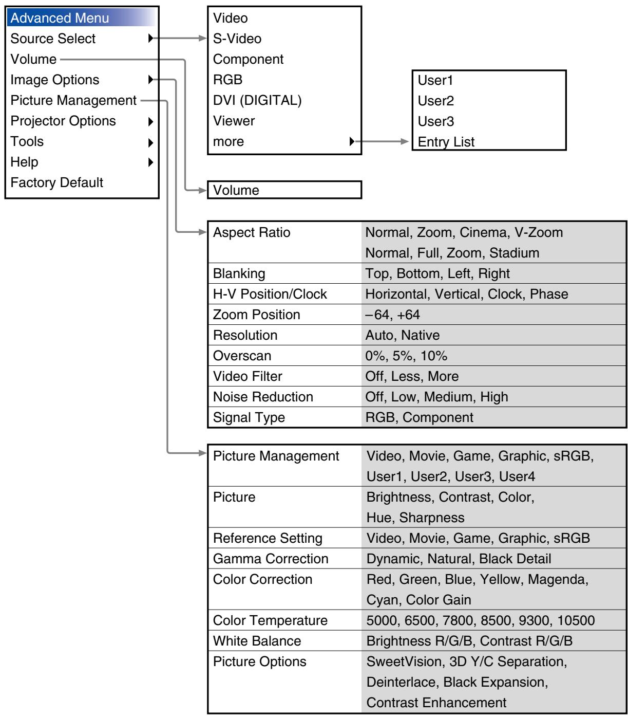
Menu tree
Menu Elements
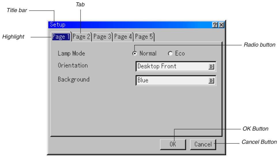
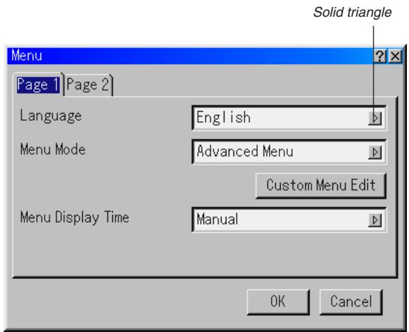
Menu windows or dialog boxes typically have the following elements:
Title bar ........ Indicates the menu title.
Highlight ......... Indicates the selected menu or item.
Solid triangle ....... Indicates further choices are available. A highlighted triangle indicates the item is active.
Tab Indicates a group of features in a dialog box. Selecting on any tab brings its page to the front.
Radio button....... Use this round button to select an option in a dialog box.
Check box ...... Place a checkmark in the square box to turn the option On.
Slide bar ........ Indicates settings or the direction of adjustment.
OK button....... Press to confirm your setting. You will return to the previous menu.
Cancel button .... Press to cancel your setting. You will return to the previous menu.
Toolbar ....... Contains several icons for specific tasks. It is also referred to as "launcher".
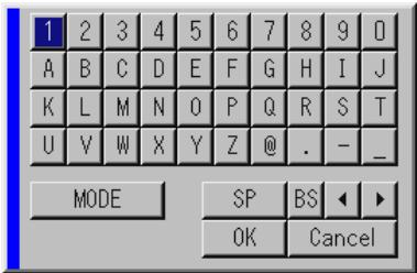
Entering Alphanumeric Characters by Using the Menu
Alphabet or numeric characters are used for your IP address or projector name. To enter IP Address or projector name, use the software keyboard.
For using the software keyboard, see page E-56.

Menu Descriptions & Functions
Source Select
Selecting a Source
Enables you to select a video source such as a VCR, DVD player, laser disc player or computer depending on what is connected to your inputs. Press the SELECT button on the projector cabinet or on your remote control to highlight the menu for the source you want to project.
Video
Selects what is connected to your Video input-VCR, laser disc player or DVD player.
S-Video
Selects what is connected to your S-Video input-VCR, DVD player, or laser disc player.
NOTE: A frame may freeze for a brief period of time when a video is played back in fast-forward or fast-rewind with a Video or S-Video source.
Component
Selects your component equipment such as DVD player connected to the COMPONENT input connectors.
RGB
Selects the computer connected to your RGB or component signal.
DVI (DIGITAL)
Selects the computer connected to the DVI input connector.
Viewer
This feature enables you to make presentations using a PC card that contains captured images and slides. The starting screen for the Viewer varies depending on the settings of the Setup's Page 2. See Setup on page E-41.
NOTE: Even if you switch the current Viewer source to another source, the current slide is retained. When you return back to the Viewer, you will get the slide that has been retained. A launcher will appear when you press the MENU button.
A press of the MENU button displays the toolbar; a press of the MENU button again displays the Menu and hereafter each press of the MENU button switches displaying between the Menu and the toolbar.
The launcher is a tool bar including the following buttons:
Prev Returns to the previous slide or folder.
Next . Advances to the next slide or folder.
Play Plays back automatically or manually depending on the setting on Viewer Options of the menu. This allows you to move on to the next slide when "Manual Play" is selected.
Stop ......... Stops Auto Play while you are playing back and to resume playing from the selected slide or folder when "Auto Play" is selected.
Jump .................... Displays a list of slides while you are playing back.
Select ..................... Displays a list of folders while you are playing back.
Setup .................... Displays the Viewer Options dialog box on Page 2 of the Setup dialog box.
Delete ........ Deleted a captured slide(s) or all the captured slides in the selected folder.
View .... Hides the tool bar while you are playing back. A press of the MENU button displays the toolbar again.
Entry List
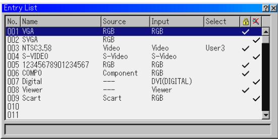
Displays the list of the entry signals. Use the SELECT buttons on your remote control or the projector cabinet to select the signal and press the ENTER button on the remote control or the projector cabinet to display the Entry Edit Command screen.
Using the Entry List
Making any adjustments to the current picture will automatically register its adjustments to the Entry List. The registered signal can be loaded any time from the Entry List.
NOTE: Up to 100 preset can be registered except settings on the Picture Management.
Entry Edit Command
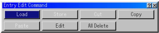
You can edit signals on the Entry List.
Load....Enables you to select a signal from the list.
Store ......... Enables you to store the currently projected signal.
Cut ......... Enables you to remove a selected signal from the list and place it on the "clipboard" in the projector.
Copy ......... Enables you to copy a selected signal from the list and place it on the "clipboard" in the projector.
Paste. Enables you to paste the signal placed on the "clipboard" to any other line of the list. To do this, select "Paste" and then select the line number you want to paste to. Last press ENTER.
Edit ......... Enables you to change source names or add source names to "More" in the Sorce Select.
Source Name .. Enter a signal name. Up to 18 alphanumeric characters can be used.
Input Terminal.. Change the input terminal. Video and S-Video are available for composite signal.
Source List .... Set signal selection method.
Lock .. Set so that the selected signal cannot be deleted when "All Delete" is executed.
Skip Set so that the selected signal will be skipped during auto search.
When complete, select OK and press ENTER. To exit without storing setting, select Cancel. Select "Source Name" and press ENTER to display the Source Name Edit window. You can change source name on this window. Press [▼] to display the software keyboard, which you can enter alphanumeric characters. See page E-56 for the key function of the software keyboard.
All Delete ....... This feature enables you to delete all the registered signals in the Entry List.
The following buttons are not available for the currently projecting signals:
1) The Cut and Paste buttons on the Entry Edit Command screen
2) The Input Terminal button on the Entry Edit screen
NOTE: When all the signals in the Entry List are deleted, the currently projected signal will be also deleted except locked signals.
Volume
Controlling Volume
Adjusts the sound level of the projector speaker.
Image Options
Selecting Aspect Ratio (not available for Viewer)
Aspect Ratio allows you to select the best Aspect mode to display your source image.
When screen size 4:3 is selected for the source, the following selections will display:
Normal ......... Standard 4:3 Aspect
Zoom ....... All 4 sides stretched
Cinema ....... Top and bottom reduced to display with black borders on top and bottom. Available for 4:3 only
V-Zoom ....... Top and bottom stretched. Available for 4:3 only
When screen size 16:9 is selected for the source, the following selections will display:
Normal 16:9 image displayed in 4:3 mode
Full ......... Stretched to display in 16:9 aspect ratio. Available for 16:9
Zoom ....... All 4 sides stretched
Stadium ....... Non-linearly stretched. Available for 16:9 only
NOTE: You can adjust image positions vertically for source with black borders. See page E-43 for setting image positions.
Copyright
Please note that using this projector for the purpose of commercial gain or the attraction of public attention in a venue such as a coffee shop or hotel and employing compression or expansion of the screen image with a "Aspect Ratio" or "Screen" setting may raise concern about the infringement of copyrights which are protected by copyright law.
NOTE: During 3D Reform adjustment, "Aspect Ratio" may not be available. Should this happen, first reset the 3D Reform data and then do setting again. Second repeat the 3D Reform adjustment.
Changing the aspect ratio can limit 3D Reform in its adjustable range.
ASPECT
When screen size 4:3 is selected for the source, the following selections will display.
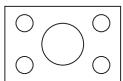
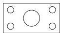
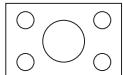
| input mode | 480i/576i | DVD progressive | 480p/576p | 720p | 1080i | 1080p | PC(RGB) |
| These are the same signals. | |||||||
| Normal | |||||||
| Zoom | |||||||
| Cinema | |||||||
| V-Zoom | |||||||
When screen size 16:9 is selected for the source, the following selections will display.
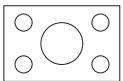
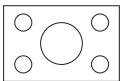
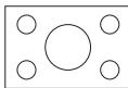
| input mode | 480i/576i | DVD progressive | 480p/576p | 720p | 1080i | 1080p | PC(RGB) |
| These are the same signals. | |||||||
| Normal | |||||||
| Full | - | - | - | ||||
| Zoom | - | - | - | ||||
| Stadium | - | - | - | ||||
Masking Unwanted Area (Blanking)
This feature allows you to mask any unwanted area of the screen image.
Adjust the Top, Bottom, Left or Right blanking with the SELECT button.
Adjusting Position and Clock
This allows you to manually adjust the image horizontally and vertically, and adjust Clock and Phase.
Horizontal/Vertical Position:
Adjusts the image location horizontally and vertically using the SE-LECT and buttons. This adjustment is made automatically when the Auto Adjust is turned on. See "Auto Adjust" on page E-41 for turning on or off the Auto Adjust feature.
Clock. Use this item to fine tune the computer image or to remove any vertical banding that might appear. This function adjusts the clock frequencies that eliminate the horizontal banding in the image.
Press the SELECT and buttons until the banding disappears. This adjustment may be necessary when you connect your computer for the first time. This adjustment is made automatically when the Auto Adjust is turned on.
Phase Use this item to adjust the clock phase or to reduce video noise, dot interference or cross talk. (This is evident when part of your image appears to be shimmering.) Use the SELECT and buttons to adjust the image.
Use "Phase" only after the "Clock" is complete. This adjustment is made automatically when the Auto Adjust is turned on.
Zoom Position
When "4:3" is selected in Screen Type:
Move the viewable area up or down
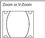
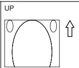
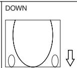
Move the position of an image up or down
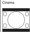
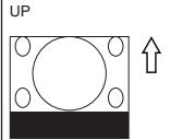
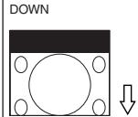
When "16:9" is selected in Screen Type:
Move the viewable area up or down
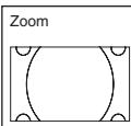
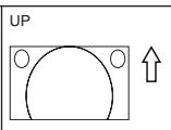
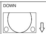
Table of Availability for Zoom Position
For PC, DVD Progressive, 480p, 480i, 576p, 576i
| Screen Type | Aspect Ratio | |||||
| Normal | Full | Zoom | Cinema | V-Zoom | Stadium | |
| 4:3 | Not available | Available | Available | Available | ||
| 16:9 | Not available | Not available | Available | Not available | ||
For 720p, 1080i, 1080p
| Screen Type | Aspect Ratio | |||||
| Normal | Full | Zoom | Cinema | V-Zoom | Stadium | |
| 4:3 | Available | Not available | Available | Not available | ||
| 16:9 | Not available | |||||
Selecting Resolution
This allows you to activate or deactivate the Advanced AccuBlend feature.
Auto ......... Turns on the Advanced AccuBlend feature. The projector automatically reduces or enlarges the current image to fit the full screen.
Native. Turns off the Advanced AccuBlend feature. The projector displays the current image in its true resolution.
See "Auto Adjust" on page E-41 for turning on or off the Auto Adjust feature.
NOTE:
- When "Resolution" is set to "Native", "3D Reform", "Aspect Ratio" and "Screen" are not available.
- While you are displaying an image with higher resolution than the projector's native resolution "Native" is not available.
Selecting Overscan Percentage
Select overscan percentage (0%, 5% and 10%) for signal.
NOTE: When "Resolution" is set to "Native", this feature is not available, and the stored settings and adjustments are invalid.
NOTE: When "Stadium" is selected in "Aspect Ratio", this feature is not available.
NOTE: The "0%" option may not be available depending upon the input signal.
Selecting Video Filter Level (not available for Video, DVI, Component 15kHz and Viewer)
This function reduces video noise.
Off . The filter is removed.
Less .... The low-pass filter is applied partially.
More .... The low-pass filter is applied fully.
Selecting Noise Reduction Level (not available for RGB, DVI and Viewer)
Select one of the three levels for reducing video noise: Low, Medium or High.
NOTE: The lower the Noise Reduction level, the better the image quality by way of higher video bandwidth.
Selecting Signal Type
Select either the RGB signal type or the Component signal type.
RGB RGB signal
Component .... Component signals such as Y/Cb/Cr, Y/Pb/Pr
NOTE: This feature is available on RGB only. If you do not get a better picture even when you set "Signal Select" to "Component" in Setup, set this to "Component".
Picture Management
This option allows you to adjust neutral tint for yellow, cyan or magenta. There are 5 factory presets optimized for various types of images, or you can set 4 user adjustable settings.
Video .........Recommended for regular picture such as TV program
Movie .......Recommended for movie
Game .Recommended for playing a video game
Graphic .......Recommended for graphics
sRGB .... Standard color values
User 1-4 ......... User adjustable
Picture (not available for DVI and Viewer)
Adjusting Brightness, Contrast, Color, Hue, and Sharpness
Brightness...... Adjusts the brightness level or the back raster intensity.
Contrast ....... Adjusts the intensity of the image according to the incoming signal.
Color ......... Increases or decreases the color saturation level (not valid for RGB).
Hue ............ Varies the color level from +/- green to +/-blue. The red level is used as reference. This adjustment is only valid for Video and Component inputs (not valid for RGB).
Sharpness .... Controls the detail of the image for Video (Not valid for RGB).
User Adjust (when using User 1 to 4)
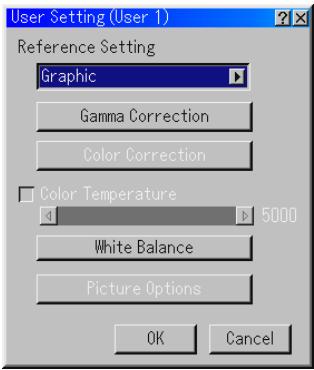
When selecting one of four user adjustable presettings (User 1 through 4), the submenu will be displayed.
You can customize each gamma or color. To do so, first select [Setting] and press the ENTER button, and then proceed the following steps.
Selecting Reference Setting
This feature allows you to use color correction or gamma values as reference data to optimize for various types of images. You can select one of the following five settings.
Video
- Movie
Game
- Graphic
sRGB
Selecting Gamma Correction Mode
Use the or buttons to choose one mode from three options.
Each mode is recommended for:
Dynamic...... High-contrast picture
Black Detail .... Dark portions of a picture
Natural ...... Natural reproduction picture
Selecting Color Correction
Adjusts red, green, blue, yellow, magenta, cyan and color gain each independently to correct the tint on whole screen.
Adjusting Color Temperature and White Balance
This feature adjusts the color temperature using the slide bar.
Checking "Color Temperature" enables the color temperature slide bar and disables the "White Balance" button.
Press the White Balance button to access the Contrast/Brightness adjustment for each R, G, and B.
NOTE: "Color Temperature" and "White Balance" are a trade-off.
The White Balance is not available for Viewer.
NOTE: When "Graphic" is selected, the available items are "Gamma" and "White Balance" only.
Picture Options
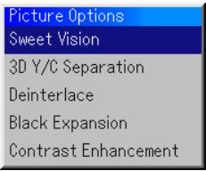
SweetVisionTM
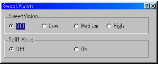
The SweetVision feature provides improvement of contrast using a proprietary detail enhancement technology.
NOTE: This feature is not available for 480p, 576p, HDTV and RGB signals.
"Off" ......... Turns off the Sweet Vision feature
"Low" .... Selects low level
"Medium" ....... Selects medium level
"High" Selects high level
Split Mode
This feature turns on or off to show the effect of the SweetVision.
3D Y/C Separation

This option turns on or off the 3 dimension separation feature.
NOTE: This feature is available for NTSC3.58 of Video signal only.
Deinterlace
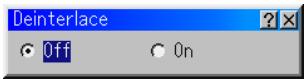
Turns on or off the deinterlace function for the telecine signal.
On Default standard setting.
Off .... Select this option if there are some jitter or artifacts in video.
NOTE: This feature is not available for 480p, 576p, HDTV and RGB signals.
Black Expansion
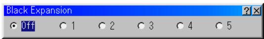
Minimizes blacks that appear more like shades of gray to provide a true black and white image at high contrast.
Off/1/2/3/4/5
NOTE: This feature is not available for 480p, 576p, HDTV and RGB signals.
Contrast Enhancement
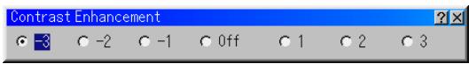
This option allows you to provide a high contrast image in a bright scene. -3/ -2 / - 1 / Off / 1 / 2 / 3
NOTE: This feature is not available for 480p, 576p, HDTV and RGB signals.
Projector Options
Using 3D Reform
This feature corrects trapezoidal distortion so that the projected image is rectangular.
Two options are available for correcting procedures.
You can save adjustment settings by using the 3D Reform Save option on Setup (See page E-42).
Keystone
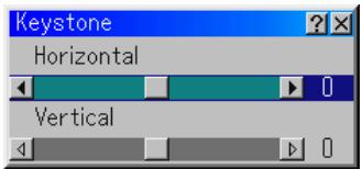
- Press the SELECT button to adjust the horizontal keystone.
- Press the SELECT button to select "Vertical".
- Press the SELECT button to adjust the vertical keystone.
- After completing, press the ENTER button. This will return to the menu screen.
Cornerstone
See page E-20
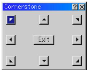
- When "Resolution" is set to "Native", "Cornerstone" and "Keystone" are not available.
Menu
Allows you to set preferences for the on-screen menu. Press "OK" to save your changes for all the features of Page 1 and Page 2.
[Page1]
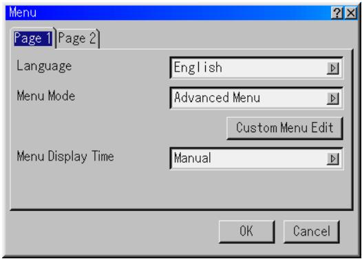
Selecting Menu Language [Language]:
You can choose one of seven languages for on-screen instructions. The options are: English, German, French, Italian, Spanish, Swedish and Japanese.
Selecting Menu Mode [Menu Mode]:
This feature allows you to select 3 menu modes: Advanced Menu, Custom Menu and Basic Menu.
Advanced Menu ....... This is the menu that contains all the available menus and commands.
Basic Menu ........ This is the basic menu that contains minimum essentials of menus and commands.
Custom Menu ........ This is the menu that you can customize using the Custom Menu Edit to fit your needs.
Customizing the Menu:
See page E-30 for instructions about how to customize the Menu.
Selecting Menu Display Time:
This option allows you to select how long the projector waits after the last touch of a button to turn off the menu.
The preset choices are "Manual", "Auto 5 sec", "Auto 15 sec", and "Auto 45 sec". The "Auto 45 sec" is the factory preset.
Manual .... The menu can be turned off manually.
Auto 5 sec...... The menu will automatically be turned off in 5 seconds if no buttons are pressed within 5 seconds.
Auto 15 sec .... The menu will automatically be turned off in 15 seconds if no buttons are pressed within 15 seconds.
Auto 45 sec .... The menu will automatically be turned off in 45 seconds if no buttons are pressed within 45 seconds.
[Page 2]
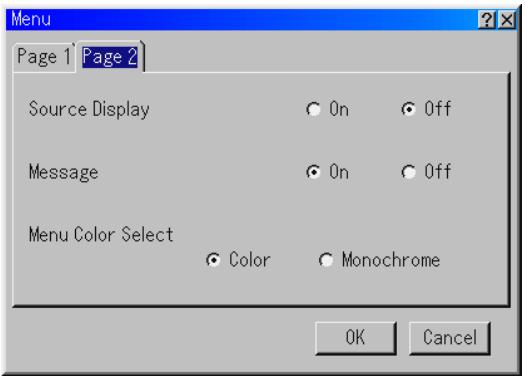
Turning On / Off Source Display [Source Display]:
This option turns on or off input name display such as RGB, Video, and No Input to be displayed in the top right corner of the screen.
Turning On / Off Message [Message]:
This option turns on and off messages for lamp life warning, 3-minute before power off time and "Please wait a moment"
Selecting Menu Color [Menu Color Select]:
You can choose between two color modes for menu color: color and monochrome.
Setup
Enables you to set operating options.
Press "OK" to save your changes for all the features of Page1, Page2, Page3, Page 4 and Page 5.
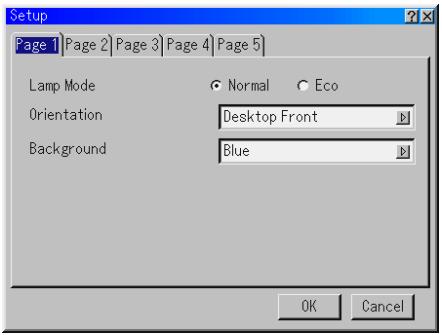
[Page 1]
Setting Lamp Mode to Normal or Eco [Lamp Mode]:
This feature enables you to select two brightness mode of the lamp: Normal and Eco modes. The lamp life can be extended up to 2000 hours by using the Eco mode.
Normal Mode. This is the default setting (100% Brightness).
Eco Mode .... Select this mode to increase the lamp life (80% Brightness).
Selecting Projector Orientation [Orientation]:
This reorients your image for your type of projection. The options are: desktop front projection, ceiling rear projection, desktop rear projection, and ceiling front projection.
Selecting a Color or Logo for Background [Background]:
Use this feature to display a blue/black screen or logo when no signal is available. The default background is blue. You can change the logo screen using the PC Card Files feature. See pages E-29 and 47.
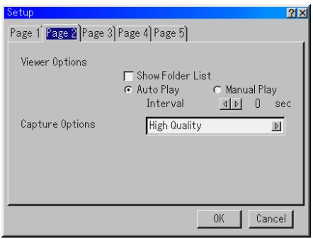
[Page 2]
Setting Viewer Options [Viewer Options]
Show Folder List:
If this option is checked, when the Viewer source is selected on the projector, the folder lists will be displayed and allows you to select the presentation from a PC card.
Auto Play:
If this option is checked, when the Viewer source is selected on the projector any given slide will start to play automatically.
Auto Play Interval:
You can specify interval time between 5 and 300 seconds.
Manual Play:
Views a slide manually when the Viewer source is selected.
Selecting Capture Options [Capture Option]: (available for JPEG only) These options are used for the Capture function that you can select from Tools. You have three options for JPEG compression quality: High quality, Normal and High Compression.
High Quality ........ Gives quality of JPEG a priority.
Normal . Gives normal JPEG quality.
High Compression ....... Gives compression a priority.

[Page 3]
Selecting Signal Format [Signal Select]
RGB:
Allows you to choose "RGB" for an RGB source such as a computer, or "Component" for a component video source such as a DVD player. Normally select "RGB/Component" and the projector automatically detects an either incoming signal. However there may be some component signals that the projector is unable to detect. If this is the case, select "Component". Select "Scart" for the European Scart.
VIDEO and S-VIDEO:
This feature enables you to select composite video standards manually. Normally select "Auto". Select the video standard from the pulldown menu. This must be done for Video and S-Video separately.
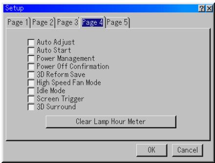
[Page 4]
Enabling Auto Adjust [Auto Adjust]:
When "Auto Adjust" is set to "On", the projector automatically determines the best resolution for the current RGB input signal to project an image using NEC's Advanced AccuBlend Intelligent Pixel Blending Technology.
The image can be automatically adjusted for position and stability, "Horizontal Position", "Vertical Position", "Clock", "Phase", and "Resolution".
On............ Automatically adjusts image "Horizontal Position", "Vertical Position", "Clock", "Phase" and "Resolution".
Off ......... User can adjust the image display functions ("Horizontal Position", "Vertical Position", "Clock", "Phase" and "Resolution") manually.
Enabling Auto Start [Auto Start]:
Turns the projector on automatically when the power cable is inserted into an active power outlet and the main power switch is turned on. This eliminates the need to always use the "Power" button on the remote control or projector cabinet.
Enabling Power Management [Power Management]:
When this option is on and there is no input for five minutes or more, the projector will automatically turn itself off.
Enabling Power Off Confirmation [Power Off Confirmation]:
This option determines whether a confirmation dialog for turning off the projector will appear or not.
Enabling Horizontal and Vertical Keystone Correction Save
[3D Reform Save]:
This option enables you to save your current 3D Reform settings. Saving your change once affects all sources. The changes are saved when you turn off the projector.
Enabling High Speed Fan Mode [High Speed Fan Mode]:
This option allows you to select two modes for fan speed:high-speed mode and normal speed mode.
When you wish to cool down the temperature inside the projector quickly, check this box.
NOTE: Enable High Speed Fan mode if you continue to use the projector for consecutive days.
Enabling Idle Mode [Idle Mode]:
The projector has two standby modes: Standby and Idle.
Standby is the mode that allows you to put the projector in the standby condition which consumes less power than the idle mode. The projector is preset for Standby at the factory.
NOTE: The HTTP server functions are not available during Standby mode.
Enabling Screen Trigger [Screen Trigger]:
When "Screen Trigger" is selected and the projector is powered ON, the screen trigger output sends a low voltage trigger to the screen controller and the screen will go down. When the projector is powered OFF the screen trigger stops sending a low voltage trigger to the screen controller and the screen will go up. Use a commercially available stereo mini cable.
Enabling 3D Surround [3D Surround]:
Turn on or off the 3D surround effect.
After turn on this option, select "OK".
Clearing Lamp Hour Meter [Clear Lamp Hour Meter]:
Reset the lamp clock back to zero. Pressing this button appears a confirmation dialog box. To reset the lamp usage hour, press "OK".
NOTE: The projector will turn off and go into standby mode after 1600 hours (up to 2100 hours in Eco mode) of service. In this condition you cannot clear the lamp hour meter on the menu. If this happens, press the "Help" button on the remote control for ten seconds to reset the lamp clock back to zero. Do this only after replacing the lamp.
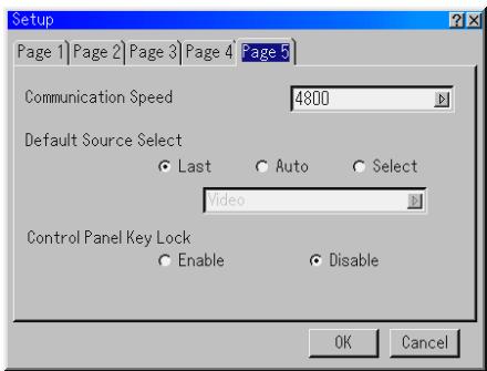
[Page 5]
Selecting Communication Speed [Communication Speed]:
This feature sets the baud rate of the PC Control port (Mini DIN 8 Pin). It supports data rates from 4800 to 38400 bps.
The default is 38400 bps. Select the appropriate baud rate for your equipment to be connected (depending on the equipment, a lower baud rate may be recommended for long cable runs).
Selecting Default Source [Default Source Select]:
You can set the projector to default to any one of its inputs each time the projector is turned on.
Last.... Sets the projector to default to the previous or last active input each time the projector is turned on.
Auto ........ Searches for an active source in order of Video S-Video Component RGB DVI (DIGITAL) Viewer Video and displays the first found source.
Select ..................... Displays the selected source input every time the projector is started up. Select an input from the pull-down menu.
Disabling the Cabinet Buttons [Control Panel Key Lock]:
This option turns on or off the Control Panel Key Lock function.
NOTE:
- This Control Panel Key Lock does not affect the remote control and the PC Control functions.
- When the cabinet buttons are disabled, pressing and holding the CANCEL button for about 10 seconds will change the setting to enabled.
Selecting Aspect Ratio and Position for Screen [Screen]
![NEC HT1000 - Selecting Aspect Ratio and Position for Screen [Screen] - 1](/content/2025/01/174234/images/982bf633c3a8d3fafa100e8495fd5531f39a0085cd354006a6c6c2e63c2fa193.jpg)
Screen Type:
Select either 4:3 Screen or 16:9 Screen for the screen to be used.
See also "Aspect Ratio" on pages E-36 and 37.
NOTE: When "Resolution" is set to "Native", this selection is inactive.
Position:
This feature adjusts the vertical position of the image when viewing video with an aspect ratio selected.
When some aspect ratios are selected in Image Options, the image is displayed with black borders on the top and bottom.
You can adjust the vertical position between top and bottom.
NOTE: This option is available only when "16:9" is selected in Screen Type.
NOTE: During 3D Reform adjustment, "Screen Type" and "Screen Position" may not be available. To make available, first reset the 3D Reform data and then do settings again. Secondly repeat the 3D Reform adjustment. Changing "Screen Type" and "Screen Position" can limit 3D Reform in its adjustable range.
Setting LAN Mode
This feature allows you to set various setting items when the projector is used on your network.
Consult with your network administrator about these settings.
CAUTION: Make sure that the LAN card is removed during Standby mode (NOT Idle mode) or with the main power off.
Failure to do so may cause damage to the data on your PC card.
Note to Users of a PCMCIA network card
Use of a non-supported network card in the projector may cause the unit to malfunction.
Should this happen, turn off the projector and remove the network card from the projector's PC card slot.
NOTE: LAN card is not available when a PC card is used for the Viewer function.
Viewer is not available when LAN card is used for LAN connection.
IP Address
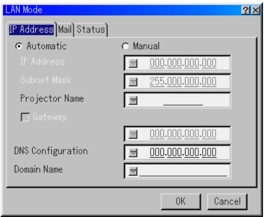
An IP address can be automatically assigned to this projector by your DHCP server. If your network does not automatically assign IP address, ask your network administrator for an address, and then register it manually.
Automatic ....... Automatically assigns an IP address to the projector from a DHCP server.
Manual ......... Provides a space for you to register the IP address or subnet mask number obtained from your network administrator.
IP Address .... Set your IP address. Press to display the software keyboard and type in 12 numeric characters.
Subnet Mask... Set your subnet mask number. Press to display the software keyboard and type in 12 numeric characters.
Projectile Name
... Specify a unique projector name. Press to display the software keyboard and type in. Up to 16 alphanumeric characters can be used.
Gateway...... Set the default gateway of the network connected to the projector. Press 口 to display the software keyboard and type in 12 numeric characters.
Checking this box will make the set default route valid. When data is sent from the LAN card, the transfer location will be searched according to the previously set routing information; however, when the transfer location has not been found as a result of the search, the data will be sent to the device that holds the IP address set here. The IP address that is set here must be one that can be identified by a search of the routing information.
DNS Configuration
Type in the IP address of DNS server on the network connected to the projector. 12 numeric characters are used.
Domain Name Type in domain name of the network connected to the projector. Up to 60 alphanumeric characters can be used.
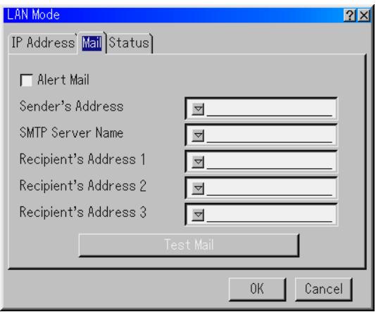
Alert Mail:
Checking this box enables Alert Mail feature.
This option notifies your computer of an error message via e-mail when using wired LAN. The error message will be notified when the projector lamp has reached the end of its usable life or an error occurs in the projector.
Sample of a message sent from the projector:
The lamp is at the end of its usable life. Please replace the lamp.
Projector Name: X X X X
Lamp Hour Meter:xxxx [H]
Projectile Usage:xxxxxxxx [H]
Sender's Address:
Specify the senders address. Use the Software keyboard. Up to 60 alphanumeric and symbols characters can be used. See "Using Software Keyboard" in Appendix for more details.
SMTP Server Name:
Type in the SMTP server name to be connected to the projector. Up to 60 alphanumeric characters can be used.
Recipient's Address 1 to 3:
Type in your recipient's address. Up to 60 alphanumeric and symbols characters can be used.
Test Mail:
Send a test mail to check if your settings are correct.
NOTE: If you entered an incorrect address in a test, you may not receive an Alert mail. Should this happen, check if the Recipient's Address is correctly set.
NOTE: Unless any one of the "Sender's Address", SMTP Server's Name" or "Recipient's Address 1-3" is selected, "Test Mail" is not available.
NOTE: Be sure to highlight "OK" and press the ENTER button before executing "Test Mail".
Status
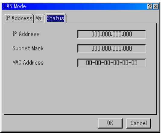
Displays the status of the LAN settings.
IP Address ....... Indicates the IP address of the projector.
Subnet Mask.. Indicates the subnet mask of the projector.
MAC Address. Indicates the MAC address of the LAN card.
Setting a Password
A password can be set for your projector to avoid operation by an unauthorized person.
There are two password options: one for menu and the other for logo. When a password is set, doing any one of the following four operations will display the Password input screen.
For Menu:
- Changing the menu to Advanced
- Editing the custom menu
For Logo:
- Changing the background
- Changing the logo data in PC Card Files
Procedures for Password setting apply to both Menu and Logo.
Entry
To assign your password:
NOTE: Up to 15 alphanumeric characters can be assigned.
- Type a password.
Highlight "Entry" and press the ENTER button.
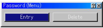
The "Enter the Password screen" will be displayed.
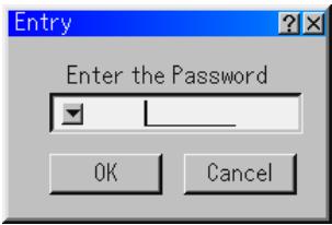
Make sure that "▼" is highlighted and then press the ENTER button. The Software keyboard appears. Use the Software keyboard to type a password and then highlight "OK" on the "Enter the Password" screen and press the ENTER button. The [Confirm Password] screen will be displayed.
- Type the same password again. Highlight "OK" on the "Enter the Password" screen and press the ENTER button.
Your password will be assigned.
Delete
To delete your password:
- Highlight [Delete] and press the ENTER button. The "Current Password" screen will be displayed.
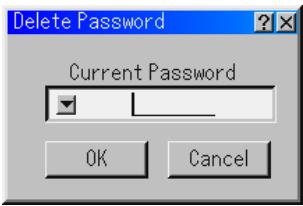
- Use the Software keyboard to type your password. Highlight "OK" on the "Current Password" screen and then press the ENTER button.
Your password will be deleted.
In case you forget your password, follow the steps below to delete it.
- Select the Advanced menu from the Basic menu. The "Password" entry screen will be displayed.
- Use the Software keyboard to type "1111".
Highlight "OK" on the "Password" entry screen and then press the ENTER button.
The "Password Warning!!" message will be displayed. - Use the Software keyboard to type "3333".
Highlight "OK" on the "Password" entry screen and then press the ENTER button.
The "Password Warning!!" message will be displayed. - Use the Software keyboard to type "5555".
Highlight "OK" on the "Password" entry screen and then press the ENTER button.
The "Delete Password. Are you sure? Yes/No" dialog box will be displayed. - Use the SELECT or button to highlight "Yes" and press the ENTER button.
Your password will be deleted.
Security
The Security function enables you to protect your projector so that the projector will not project a signal unless you enter a keyword. There is also an option to lock the projector by using a registered PC card as a protect key. Once you have registered your PC card as a protect key, you are required to insert the registered PC card into the PC card slot of the projector each time you turn on the projector. You can enable the Security function by using a keyword only.
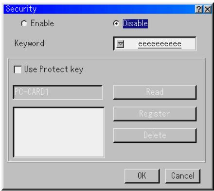
Enable/Disable. This turns the Security function on or off.
Keyword. Enter an appropriate keyword when you use the Security function.. (Up to 10 characters can be used.) The Security function is available only when your keyword is entered.
Use Protect key Check this box to lock your projector when using a PC card. To use a keyword without a PC card, do not check this box.
Read Reads data of a PC card.
Register Registers data of the PC card. The Security function is not available unless at least one PC card is registered. (if the "Use Protect key" check box is selected)
Up to 5 PC cards can be registered.
Delete Deleted data of a registered PC card.
To set up a keyword to enable the Security function without using a registered PC card.
- Use the SELECT button to select "Keyword" and use the software keyboard to enter a keyword.
NOTE: Please make a note of your keyword.
- Use the SELECT button to select "Enable" and use the SELECT button to select "OK", then the Security function will be enabled. An "Are you sure?" message will appear. Use the SELECT button and press the ENTER button. The Security function takes effect.
To register a PC card as a protect key.
- Insert a PC card into the PC card slot of the projector.
- Use the SELECT button to select "Use Protect Key" and press the ENTER button.
- Use the SELECT button to select "Read" and press the ENTER button.
Data of the PC card will be read into the projector.
- Use the SELECT button to select "Register" and press the ENTER button.
Downloaded data will be registered and be displayed in the list window.
- Use the SELECT button to select "Keyword" and use the software keyboard to enter a keyword.
NOTE: To use a PC card as a protect key, you must also set up a keyword. Please make a note of your keyword.
This completes registration of your PC card.
To enable Security, use the SELECT button to select "Enable" and use the SELECT button to select "OK" and "Security function will be enabled. An "Are you sure?" message will appear. Use the SELECT button and press the ENTER button.
The Security function takes effect.
To turn on the projector when Security is enabled (when using your keyword only).
- Press and hold the POWER button for a minimum of two seconds. The projector will be turned on and display a message to the effect that the projector is security-protected.
- Select [Projector Options] [Security] from the menu and press the ENTER button.
The Release Code input screen will be displayed.
- Enter your keyword in the Release Code input screen. You can view the projected image.
NOTE: Do not forget your keyword. However, if you forget your keyword, NEC or your dealer will provide you with your Release Code. See more information at the end of this section.
To turn on the projector when Security is enabled (when using a PC card as a protect key).
- Insert your registered PC card into the PC card slot.
-
Press and hold the POWER button for a minimum of two seconds. The projector will turn on and then recognize the PC card. Once the image has been projected, it will stay on without the PC card.
-
The security disable mode is maintained until the main power is turned off (by setting the main power switch to "O" or unplugging the power cord). In the following cases you will be asked to check the protect key or input the keyword:
(1) When "OK" is selected at an image for which security is set and the power is turned off then back on
(2) When the main power is turned off then back on while the security function is enabled
(3) When you attempt to display an image for which security is set while the security function is enabled
- Blanks (spaces) cannot be used in the Keyword section.
To delete PC card data you registered.
- Use the SELECT button to select "Delete" and use the SELECT button to select the list window.
- Use the SELECT button to select the PC card data you wish to delete.
- Press the SELECT button to select "Delete" and press the ENTER button.
The PC card data will be deleted.
If you've lost your registered PC card, proceed as follows:
NOTE: NEC or your dealer will provide you with your Release Code in exchange for your registered keyword and Request Code. See more information at the end of this section.
- Press and hold the POWER button for a minimum of two seconds. The projector will be turned on and display a message to the effect that the projector is security-protected.
- Select [Projector Options] [Security] from the menu and press hte ENTER button.
The Release Code input screen will be displayed as well as your Request Code (24 alphanumeric characters).
- Enter your Release Code in the Release Code Input screen. The projector will turn on.
- If the projector is turned on by entering the Release Code, your Security will be disabled.
NOTE:
- Some types of PC cards cannot be registered as your protect key.
- It is recommended that you register two or more PC cards in case you lose or damage your registered PC card.
- Formatting your registered PC card will disable your protect key function.
NOTE:
For additional information visit:
US : http://www.necvisualsystems.com
Europe : http://www.nec-europe.com/
Global: http://www.nec-pj.com/
Tools
Provides tools for setting sleep timer, capturing images and displaying files or changing your background logo in a PC Card.
NOTE: The "Capture" and "PC Card Files" features are required for a PC card.
Using Sleep Timer
- Select your desired time between 30 minutes and 16 hours: Off, 0:30, 1:00, 2:00, 4:00, 8:00, 12:00, 16:00.
- Select "Set" and press the ENTER button on the remote control.
- The remaining time starts counting down.
- The projector will turn off after the countdown is complete.
NOTE:
- To cancel the preset time, set "Off" for the preset time or turn off the power.
- When the remaining time reaches 3 minutes before the projector is turned off, the "Projector will turn off in 3 minutes" message will be displayed on the bottom of the screen.
Using Capture
Allows you to capture an image from a source that is currently being displayed. The image is saved as JPEG in the PC card. When you select Capture from the menu, you will get a tool bar. You can capture an image directly using the tool bar when the menu is not displayed. See page E-28.
Using PC Card Files
The PC Card Files feature allows you to display a list of all the files stored in the PC card so that you can select a file you want to display. You can also sort files by file name or date, or display the file. See page E-29.
Changing Background Logo
You can change the default background logo using the PC Card Files feature. See page E-25 and 29.
NOTE: File size must be 256KB or less. Other file formats than JPEG and BMP are not available.
Help
Contents
Provides an online help about how to use the menus. An underlined link means that you can move to an adjustment item directly.
Selecting the underlined link and pressing ENTER moves to the corresponding adjustment item.
Information
Displays the status of the current signal, and the lamp and the projector usage hours. This dialog box has three pages.
The information included are as follows:
[Page 1]
Source Name
Input Terminal
Entry No.
Horizontal Frequency
Vertical Frequency
Sync Polarity
[Page 2]
Signal Type
Video Type
Sync Type
Interlace
[Page 3]
Remaining Lamp Time (%)
Lamp Hour Meter (H)
Projectile Usage (H)
NOTE: The progress indicator shows the percentage of remaining bulb life. The value informs you of the amount of lamp and projector usage respectively.
Remaining Lamp Time Display
When the remaining lamp time reaches 0, the Remaining Lamp Time bar indicator changes from 0% to 100 Hours and starts counting down. If the remaining lamp time reaches 0 hours, the projector will not turn on regardless of whether the lamp mode is set to Normal or Eco.
Returning to Factory Default
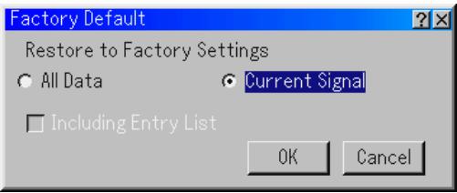
The Factory Default feature allows you to change adjustments and setting to the factory preset for source except the following:
All Data ........ Reset all the adjustments and settings for all the signals to the factory preset except Remaining Lamp Time, Lamp Hour Meter, Projector Usage, Language, Background, Entry List, Communication Speed, LAN mode, Security and Password. (To reset the lamp usage time, see "Clear Lamp Hour Meter" on page E-42) Including Entry List: Also deletes all the signals in the Entry List and returns to the factory preset.
Current Signal.... Resets the adjustments for the current signal to the factory preset levels.
All the items in "Volume", "Image Options (except Zoom Position)" and "Picture Management" can be reset.
This section describes the simple maintenance procedures you should follow to replace the lamp, and to clean the cabinet and the lens.
Replacing the Lamp
After your lamp has been operating for 1500 hours (up to 2000 hours : Eco mode) or longer, the "Lamp" indicator in the cabinet will blink red and the message will appear. Even though the lamp may still be working, replace it at 1500 hours (up to 2000 hours : Eco mode) to maintain optimal projector performance.
CAUTION
- DO NOT TOUCH THE LAMP immediately after it has been used. It will be extremely hot. Turn the projector off, wait 90 seconds, turn off the main power switch, and then disconnect the power cable. Allow at least one hour for the lamp to cool before handling.
- DO NOT REMOVE ANY SCREWS except the lamp cover screw and two lamp case screws. You could receive an electric shock.
- The projector will turn off and go into stand by mode after 1600 hours (up to 2100 hours : Eco mode) of service. If this happens, be sure to replace the lamp. If you continue to use the lamp after 1500 hours (up to 2000 hours : Eco mode) of use, the lamp bulb may shatter, and pieces of glass may be scattered in the lamp housing. Do not touch them as the pieces of glass may cause injury.
If this happens, contact your NEC dealer for lamp replacement.
To replace the lamp:
- Loosen the lamp cover screw until the screwdriver goes into a freewheeling condition and remove the lamp cover. The lamp cover screw is not removable.
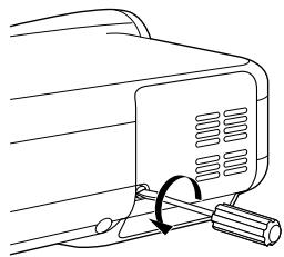
- Loosen the two screws securing the lamp housing until the screwdriver goes into a freewheeling condition. The two screws are not removable.
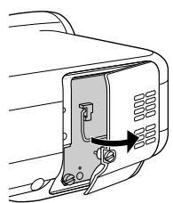
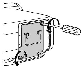
- Remove the lamp housing by pulling out the handle.
NOTE: There is an interlock on this case to prevent the risk of electrical shock. Do not attempt to circumvent this interlock.
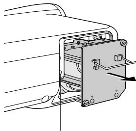
Interlock
- Insert a new lamp housing until the lamp housing is plugged into the socket.
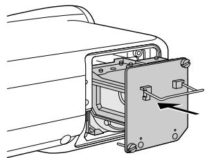
CAUTION: Do not use a lamp other than the NEC replacement lamp (LT60LP).
- Secure it in place with the two screws. Be sure to tighten the screws.
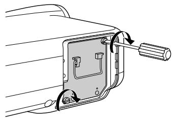
- Reattach the lamp cover.
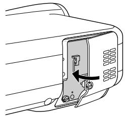
- Tighten the lamp cover screw. Be sure to tighten the screw.
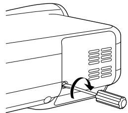
- After you install a new lamp, from the menu select [Projector Options] [Setup] [Page 4] [Clear Lamp Hour Meter] to reset the lamp usage hours.
If the projector will not be turned on after using 1600 hours (up to 2100 hours : Eco mode) of service, press and hold the [Help] button on the remote control for ten seconds or longer to reset the lamp time clock to zero.
Cleaning
Cleaning the Cabinet and the Lens
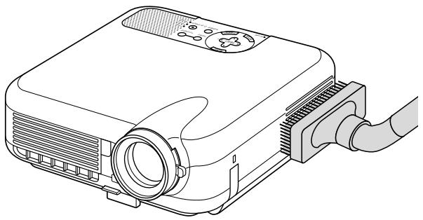
- Turn off the projector before cleaning.
- Clean the cabinet periodically with a damp cloth. If heavily soiled, use a mild detergent. Never use strong detergents or solvents such as alcohol or thinner.
- Use a blower or lens paper to clean the lens, and be careful not to scratch or mar the lens.
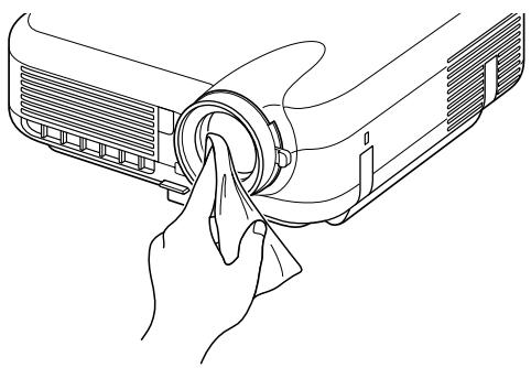
Lens Protector
The lens barrel has threads on the outside for mounting a commercially available lens protector (φ 82mm) to protect the lens from dirt, dust, scratches and damage. Note that both a lens protector and the supplied lens cap cannot be used at the same time.
CAUTION: Use only transparent lens protectors designed for lens protection. Use of filters for light reduction and special effects, such as ND (Neutral Density) filters and color filters, can absorb heat, resulting in damage to the filter and the projector.
This section helps you resolve problems you may encounter while setting up or using the projector.
Power Indicator
| Indicator Condition | Projector Condition | Note | ||
| Off | The main power is off | - | ||
| Blinking light | Green blinking | 0.5 sec ON, 0.5 sec OFF | The projector is getting ready to turn on. | Wait for a moment. |
| Green blinking | 2.5 sec ON, 0.5 sec OFF | The projector is in Sleep mode. | - | |
| Orange blinking | 0.5 sec ON, 0.5 sec OFF | The projector is cooling down. | Wait for a moment. | |
| Steady light | Green | The projector is turned on. | - | |
| Orange | The projector is in Standby or Idle. | - | ||
Status Indicator
| Indicator Condition | Projector Condition | Note | ||
| Off | Normal | - | ||
| Blinking light | Red blinking | 1 cycle (0.5 sec ON, 2.5 sec OFF) | Lamp cover error | Replace the lamp cover correctly. |
| 2 cycle (0.5 sec ON, 0.5 sec OFF) | Temperature error | The projector is overheated. Move the projector to a cooler location. | ||
| 3 cycle (0.5 sec ON, 0.5 sec OFF) | Power error | Power unit will not work correctly. | ||
| 4 cycle (0.5 sec ON, 0.5 sec OFF) | Fan error | Fans will not work correctly. | ||
| 6 cycle (0.5 sec ON, 0.5 sec OFF) | Lamp error | Lamp fails to light. Wait a full minute and then turn on again. | ||
| Green blinking | Re-firing the lamp | The projector is re-firing. | ||
| Steady light | Orange | Control key locked | You have pressed control panel key when Control Key Lock is enabled. | |
| Green | Idle condition | - | ||
Lamp Indicator
| Indicator Condition | Projector Condition | Note | |
| Off | Normal | - | |
| Blinking light | Red | Lamp has reached its end of life. Lamp replacement message will be displayed. | Replace the lamp. |
| Steady light | Red | Lamp has been used beyond its limit. The projector will not turn on until the lamp is replaced. | Replace the lamp. |
| Green | Lamp mode is set to Eco mode | - | |
Common Problems & Solutions
| Problem | Check These Items |
| Does not turn on | ·Check that the power cable is plugged in and that the power button on the projector cabinet or the remote control is on. See pages E-17 and 18. ·Ensure that the lamp cover is installed correctly. See page E-48. ·Check to see if the projector has overheated or the lamp usage exceeds 1600 hours (up to 2100 hours : Eco mode). If there is insufficient ventilation around the projector or if the room where you're presenting is particularly warm, move the projector to a cooler location. |
| No picture | ·Use the menu to select your source (Video, S-Video, Component, RGB, DVI (DIGITAL) or Viewer). See page E-19. ·Ensure your cables are connected properly. ·Use menus to adjust the brightness and contrast. See page E-39. ·Remove the lens cap. ·Reset the settings or adjustments to factory preset levels using the Factory Default in the Adjustment Menu. See page E-47. |
| Image isn't square to the screen | ·Reposition the projector to improve its angle to the screen. See page E-19. ·Use the 3DReform function to correct the trapezoid distortion. See page E-20. |
| Picture is blurred | ·Adjust the focus. See page E-20. ·Reposition the projector to improve its angle to the screen. See page E-19. ·Ensure that the distance between the projector and screen is within the adjustment range of the lens. See page E-12. ·Condensation may form on the lens if the projector is cold, brought into a warm place and is then turned on. Should this happen, let the projector stand until there is no condensation on the lens. |
| Image is scrolling vertically, horizontally or both | ·Use menus or Source button on the remote control or the cabinet to select the source you want to input. |
| Remote control does not work | ·Install new batteries. See page E-10. ·Make sure there are no obstacles between you and the projector. ·Stand within 22 feet (7 m) of the projector. See page E-10. |
| Indicator is lit or blinking | ·See the Status Indicator on page E-50. |
| Cross color in RGB mode | ·If Auto Adjust is off, turn it on or adjust the image manually with the Position/Clock in the Image Options. See page E-38 and 41. |
When using the Viewer function
| Problem | Check These Items |
| No picture | • Is “Viewer” selected from the Source menu? • Is the PC card seated in the PC Crad slot completely? • Are slide data stored in the PC card? • Have the contents of the PC card been destroyed? |
| Contents of PC Card are damaged | • Use a computer, etc., to repair the data. |
For more information contact your dealer.
What is HDCP/HDCP technology?
HDCP is an acronym for High-bandwidth Digital Content Protection. High bandwidth Digital Content Protection (HDCP) is a system for preventing illegal copying of video data sent over a Digital Visual Interface (DVI).
If you are unable to view material via the DVI input, this does not necessarily mean the projector is not functioning properly. With the implementation of HDCP, there may be cases in which certain content is protected with HDCP and might not be displayed due to the decision/intention of the HDCP community (Digital Content Protection, LLC).
This section provides technical information about the HT1000 Projector's performance
| Model Number | HT1000 |
| Optical | |
| DMDTM | Single Chip Digital Micromirror Device (DMDTM) |
| Resolution | 1024×768 pixels up to 1080p (1920×1080) with Advanced AccuBlend |
| Lens | Manual zoom and focus: F2.5 - 2.8 f = 22.4mm - 27.0mm |
| Lamp | 220 W DC standard |
| Image Size | 30" - 200" (0.8 m - 5.08 m) diagonal (4:3) 40" - 200" (1.0 m - 5.08 m) diagonal (16:9) |
| Projection Distance | 2.95ft - 24.93ft / 0.9m - 7.6m |
| Projection Angle | 18.6° - 19.4°(wide) / 15.7° - 16.2°(tele) |
| Electrical | |
| Inputs | 1 RGB, 1 S-Video, 1 Video, 1 Component, 1 DVI digital, 1 PC Card, 4 Stereo Mini Audio, 1 PC Control |
| Outputs | 1 SC.Trigger |
| Video Compatibility | NTSC, NTSC4.43, PAL, PAL-60, PAL-N, PAL-M, SECAM, Component: 1080p, 1080i, 720p, 576p, 480p, 576i, 480i |
| Scan Rate | Horizontal: 15 kHz to 69 kHz (RGB: 24 kHz or over) / Vertical: 48 Hz to 88 Hz |
| Video Bandwidth | RGB: 100 MHz (-3dB) |
| Pixel Clock Freq | Less than 100 MHz |
| Color Reproduction | 16.7 million colors simultaneously, Full color |
| Horizontal Resolution | NTSC / NTSC4.43/PAL / YCbCr: 540 TV lines SECAM: 300 TV lines RGB: 1024 dots (H) × 768 dots (V), |
| External Control | RS232C, IR, LAN (wired) |
| Sync Compatibility | Separate Sync / Composite Sync / Sync on G |
| Built-in Speakers | 2W×2 (stereo) |
| Power Requirement | 100 - 120V AC / 200 - 240V AC, 50 / 60 Hz |
| Input Current | 3.2A (100 - 120V AC) / 1.6A (200 - 240V AC) |
| Power Consumption | 290W (0.8W Standby) |
| Mechanical | |
| Installation | Orientation: Desktop/Front, Desktop/Rear, Ceiling/Front, Ceiling/Rear |
| Dimensions | 10.2" (W) × 3.6" (H) × 10.8" (D) 260mm (W) × 92mm (H) × 275mm (D) (not including protrusions) |
| Net Weight | 7.1 lbs / 3.2 kg |
| Environmental Considerations | |
| Operational Temperatures : | 41°F to 95°F (5°C to 35°C), 20% to 80% humidity (non-condensing) |
| Storage Temperatures : | 14°F to 122°F (-10°C to 50°C), 20% to 80% humidity (non-condensing) |
| Regulations | UL Approved (UL 1950, CSA 950) Meets DOC Canada Class B requirements Meets FCC Class B requirements Meets AS/NZS3548 Class B Meets EMC Directive (EN55022:1998, EN55024-1998, EN61000-3-2, EN61000-3-3) Meets Low Voltage Directive (EN60950, TUV GS Approved) |
For additional information visit:
US : http://www.necvisualsystems.com
Europe : http://www.nec-europe.com/
Global: http://www.nec-pj.com/
Digital Light Processing, DLP, Digital Micromirror Device and DMD are trademarks of Texas Instruments.
The specifications are subject to change without notice.

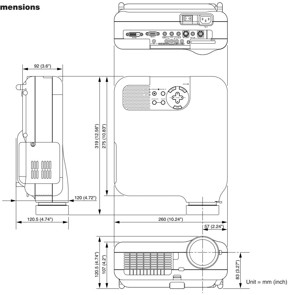
Cabinet Dimensions
Pin Assignments of D-Sub RGB Input Connector
Mini D-Sub 15 Pin Connector
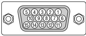
Signal Level
Video signal: 0.7Vp-p (Analog)
Sync signal : TTL level
| Pin No. | RGB Signal (Analog) | YCbCr Signal |
| 1 | Red | Cr |
| 2 | Green or Sync on Green | Y |
| 3 | Blue | Cb |
| 4 | Ground | |
| 5 | Ground | |
| 6 | Red Ground | Cr Ground |
| 7 | Green Ground | Y Ground |
| 8 | Blue Ground | Cb Ground |
| 9 | No Connection | |
| 10 | Sync Signal Ground | |
| 11 | SCART Sync | Sync |
| 12 | Bi-directional DATA (SDA) | |
| 13 | Horizontal Sync or Composite Sync | |
| 14 | Vertical Sync | |
| 15 | Data Clock |
Compatible Input Signal List
| Signal | Resolution (Dots) | Frequency H. (kHz) | Refresh Rate (Hz) | Dot Clock (MHz) |
| NTSC | - | 15.734 | 60 | - |
| PAL | - | 15.625 | 50 | - |
| SECAM | - | 15.625 | 50 | - |
| VESA | 640 × 480 | 31.47 | 59.94 | 25.175 |
| IBM | 640 × 480 | 31.47 | 60 | 25.175 |
| MAC | 640 × 480 | 31.47 | 60 | 25.175 |
| MAC | 640 × 480 | 34.97 | 66.67 | 31.334 |
| MAC | 640 × 480 | 35 | 66.67 | 30.24 |
| VESA | 640 × 480 | 37.86 | 72.81 | 31.5 |
| VESA | 640 × 480 | 37.5 | 75 | 31.5 |
| IBM | 640 × 480 | 39.375 | 75 | 31.49 |
| VESA | 640 × 480 | 43.269 | 85.01 | 36 |
| IBM | 720 × 350 | 31.469 | 70.09 | 28.322 |
| VESA | 720 × 400 | 37.927 | 85.04 | 35.5 |
| IBM | 720 × 350 | 39.44 | 87.85 | 35.5 |
| IBM | 720 × 400 | 39.44 | 87.85 | 35.5 |
| VESA | 800 × 600 | 35.16 | 56.25 | 36 |
| VESA | 800 × 600 | 37.879 | 60.32 | 40 |
| VESA | 800 × 600 | 48.077 | 72.19 | 50 |
| VESA | 800 × 600 | 46.88 | 75 | 49.5 |
| VESA | 800 × 600 | 53.674 | 85.06 | 56.25 |
| MAC | 832 × 624 | 49.725 | 74.55 | 57.283 |
| VESA | 1024 × 768 | 35.5 | 43 Interlaced | 44.9 |
| VESA | 1024 × 768 | 48.363 | 60 | 65 |
| VESA | 1024 × 768 | 56.476 | 70.07 | 75 |
| MAC | 1024 × 768 | 60.241 | 74.93 | 80 |
| VESA | 1024 × 768 | 60.023 | 75.03 | 78.75 |
| VESA | 1024 × 768 | 68.677 | 85 | 94.5 |
| # HDTV(1080p) | 1920 × 1080 | 67.5 | 60 Progressive | - |
| # HDTV(1080i)(1125i) | 1920 × 1080 | 33.75 | 60 Interlace | 74.25 |
| # HDTV(1080i)(1125i) | 1920 × 1080 | 28.13 | 50 Interlace | 74.25 |
| # HDTV(720p)(750p) | 1280 × 720 | 45 | 60 Progressive | 74.25 |
| SDTV(480p)(525p) | 720 × 480 | 31.47 | 59.94 Progressive | 27 |
| SDTV(576p)(625p) | 720 × 576 | 31.25 | 50 Progressive | 27 |
| Set-top box YCbCr | 1440 × 480 | 15.734 | 59.94 Interlaced | 27 |
Images in above flagged with # are compressed with Advanced AccuBlend.
NOTE: Some composite sync signals may not be displayed correctly.
Signals other than those specified in the table above may not be displayed correctly. If this should happen, change the refresh rate or resolution on your PC. Refer to Display Properties help section of your PC for procedures.
Compatible Input Signal List for DVI Signal (RGB only)
| Signal | Resolution ( Dots ) | Frequency H. ( kHz ) | Refresh Rate ( Hz ) | Dot Clock ( MHz ) |
| VESA | 640 × 480 | 31.47 | 59.94 | 25.175 |
| IBM | 640 × 480 | 31.47 | 60 | 25.175 |
| MAC | 640 × 480 | 31.47 | 60 | 25.175 |
| MAC | 640 × 480 | 34.97 | 66.67 | 31.334 |
| MAC | 640 × 480 | 35 | 66.67 | 30.24 |
| VESA | 640 × 480 | 37.86 | 72.81 | 31.5 |
| VESA | 640 × 480 | 37.5 | 75 | 31.5 |
| IBM | 640 × 480 | 39.375 | 75 | 31.49 |
| VESA | 640 × 480 | 43.269 | 85.01 | 36 |
| IBM | 720 × 350 | 31.469 | 70.09 | 28.322 |
| VESA | 720 × 400 | 37.927 | 85.04 | 35.5 |
| IBM | 720 × 350 | 39.44 | 87.85 | 35.5 |
| IBM | 720 × 400 | 39.44 | 87.85 | 35.5 |
| VESA | 800 × 600 | 35.16 | 56.25 | 36 |
| VESA | 800 × 600 | 37.879 | 60.32 | 40 |
| VESA | 800 × 600 | 48.077 | 72.19 | 50 |
| VESA | 800 × 600 | 46.88 | 75 | 49.5 |
| VESA | 800 × 600 | 53.674 | 85.06 | 56.25 |
| MAC | 832 × 624 | 49.725 | 74.55 | 57.283 |
| VESA | 1024 × 768 | 35.5 | 43 Interlaced | 44.9 |
| VESA | 1024 × 768 | 48.363 | 60 | 65 |
| VESA | 1024 × 768 | 56.476 | 70.07 | 75 |
| MAC | 1024 × 768 | 60.241 | 74.93 | 80 |
| VESA | 1024 × 768 | 60.023 | 75.03 | 78.75 |
| VESA | 1024 × 768 | 68.677 | 85 | 94.5 |
| # HDTV(1080i)(1125i) | 1920 × 1080 | 33.75 | 60 Interlace | 74.25 |
| # HDTV(1080i)(1125i) | 1920 × 1080 | 28.13 | 50 Interlace | 74.25 |
| # HDTV(720p)(750p) | 1280 × 720 | 45 | 60 Progressive | 74.25 |
| SDTV(480p)(525p) | 720 × 480 | 31.47 | 59.94 Progressive | 27 |
| SDTV(576p)(625p) | 720 × 576 | 31.25 | 50 Progressive | 27 |
| Set-top box YCbCr | 1440 × 480 | 15.734 | 59.94 Interlaced | 27 |
: Images in above flagged with # are compressed with Advanced AccuBlend.
- The "0%" overscan is not available.
NOTE: Some composite sync signals may not be displayed correctly.
Signals other than those specified in the table above may not be displayed correctly. If this should happen, change the refresh rate or resolution on your PC. Refer to Display Properties help section of your PC for procedures.
PC Control Codes and Cable Connection
PC Control Codes
| Function | Code Data | |||||||
| POWER ON | 02H | 00H | 00H | 00H | 00H | 02H | ||
| POWER OFF | 02H | 01H | 00H | 00H | 00H | 03H | ||
| INPUT SELECT RGB | 02H | 03H | 00H | 00H | 02H | 01H | 01H | 09H |
| INPUT SELECT COMPONENT | 02H | 03H | 00H | 00H | 02H | 01H | 10H | 18H |
| INPUT SELECT VIDEO | 02H | 03H | 00H | 00H | 02H | 01H | 06H | 0EH |
| INPUT SELECT S-VIDEO | 02H | 03H | 00H | 00H | 02H | 01H | 0BH | 13H |
| INPUT SELECT DVI (DIGITAL) | 02H | 03H | 00H | 00H | 02H | 01H | 1AH | 22H |
| INPUT SELECT VIEWER | 02H | 03H | 00H | 00H | 02H | 01H | 1FH | 27H |
| PICTURE MUTE ON | 02H | 10H | 00H | 00H | 00H | 12H | ||
| PICTURE MUTE OFF | 02H | 11H | 00H | 00H | 00H | 13H | ||
| SOUND MUTE ON | 02H | 12H | 00H | 00H | 00H | 14H | ||
| SOUND MUTE OFF | 02H | 13H | 00H | 00H | 00H | 15H | ||
| ON SCREEN MUTE ON | 02H | 14H | 00H | 00H | 00H | 16H | ||
| ON SCREEN MUTE OFF | 02H | 15H | 00H | 00H | 00H | 17H | ||
NOTE: Contact your local dealer for a full list of PC Control Codes if needed.
Cable Connection
Communication Protocol
Baud rate 38400 bps
Data length 8 bits
Parity . No parity
Stop bit . One bit
X on/off None
Communications procedure. Full duplex
NOTE: Depending on the equipment, a lower baud rate may be recommended for long cable runs.
PC Control Connector (DIN-8P)
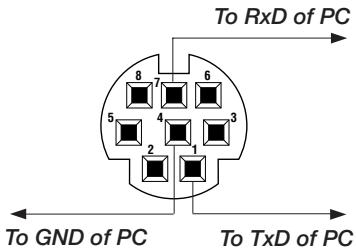
NOTE: Pins 2, 3, 5, 6 and 8 are used inside the projector.
Using Software Keyboard
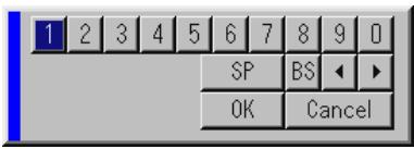
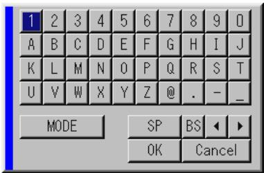
1 to 0 and Characters
Use to type in IP address or projector name
SP ......... Inserts a space
BS ........ Deleted one character backward
< Returns to the previous
Advances to the next
OK......Executes the selection
Cancel ....... Cancels the selection
MODE .... Selects one of three modes for alphabet and special characters.
Operation Using an HTTP Browser
Overview
The use of HTTP server functions will allow control of the projector from a web browser without the installation of special software. Please be sure to use "Microsoft Internet Explorer 4.x" or a higher version for the web browser. (This device uses "JavaScript" and "Cookies" and the browser should be set to accept these functions. The setting method will vary depending on the version of browser. Please refer to the help files and the other information provided in your software.)
NOTE:
- The use of HTTP server functions is not available during Standby mode.
- The display's or button's response can be slowed down or operation may not be accepted depending the settings of your network. Should this happen, consult your network administrator.
- The projector may not respond if its buttons are repeatedly pressed in rapid intervals. Should this happen, wait a moment and repeat. If you still can't get any response, pull out and then re-insert the LAN card.
Access is gained to the HTTP server functions by specifying http://
Preparation Before Use
Make network connections and set up the projector and confirm that it is complete before engaging in browser operations. (See "Setting LAN Mode" on page E-43.)
Operation with a browser that uses a proxy server may not be possible depending on the type of proxy server and the setting method. Although the type of proxy server will be a factor, it is possible that items that have actually been set will not be displayed depending on the effectiveness of the cache, and the contents set from the browser may not be reflected in operation. It is recommended that a proxy server not be used unless it is unavoidable.
Handling of the Address for Operation via a Browser
Regarding the actual address that is entered for the address or entered to the URL column when operation of the projector is via a browser, the host name can be used as it is when the host name corresponding to the IP address of the projector has been registered to the domain name server by a network administrator, or the host name corresponding to the IP address of the projector has been set in the "HOSTS" file of the computer being used.
Example 1: When the host name of the projector has been set to "pj.nec.co.jp", http://pj.nec.co.jp/index.html is specified for the address or the entry column of the URL.
Example 2: When the IP address of the projector is "192.168.73.1", access is gained to the HTTP server functions by specifying http://192.168.73.1/index.html for the address or the entry column of the URL.
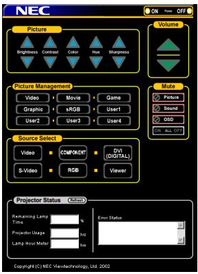
Structure of the HTTP Server
Power: This controls the power of the projector.
On ......... Power is switched on.
Off ......... Power is switched off.
Volume: This controls the volume of the projector.
. Increments the volume adjustment value.
. Decrements the volume adjustment value.
Mute: This controls the mute function of the projector.
All On ........ Mutes each of the video, audio, and on-screen display functions.
All Off ......... Cancels the muting of each of the video, audio, and on-screen display functions.
Picture On.... Mutes the video.
Picture Off ....... Cancel the video muting.
Sound On ....... Mutes the audio.
Sound Off ....... Cancels the audio muting.
OSD On ........ Mutes the on-screen display.
OSD Off ....... Cancels the muting of the on-screen display.
Picture: Controls the video adjustment of the projector.
Brightness Increments the brightness adjustment value.
Brightness .Decrements the brightness adjustment value.
Contrast .... Increments the contrast adjustment value.
Contrast .... Decrements the contrast adjustment value.
Color ....... Increments the color adjustment value.
Color . Decrements the color adjustment value.
Hue . . increments the hue adjustment value.
Hue . Decrements the hue adjustment value.
Sharpness ▲. Increments the sharpness adjustment value.
Sharpness . Decrementsthe sharpness adjustment value.
- The functions that can be controlled will vary depending on the signal being input to the projector.
Picture Management
Video ......... Switches to Video mode.
Movie ......... Switches to Movie mode.
Game ......... Switches to Game mode.
Graphic ......... Switches to Graphic mode.
sRGB ......... Switches to sRGB mode.
User1 - 4 .... Switches to User mode (1 to 4).
Source Select: This switches the input connector of the projector.
Video ......... Switches to the Video connector.
S-Video ......... Switches to the S-Video connector.
Component .... Switches to the Component connectors.
RGB ......... Switches to the RGB connector.
DVI (DIGITAL) Switches to the DVI-D connector.
Viewer ......... Switches to the Viewer.
Projector Status: This displays the condition of the projector.
Remaining Lamp Time.. Displays the remaining life of the lamp as a percentage.
Lamp Hour Meter ..................... Displays how many hours the lamp has been used.
Projector Usage .................... Displays how many hours the projector has been used.
Error Status .................... Displays the status of errors occurring within the projector.
Refresh ......... Updates the display of the following conditions.
TravelCare Guide
TravelCare - a service for international travelers
This product is eligible for "TravelCare", NEC's unique international warranty.
Please note that TravelCare coverage differs in part from coverage under the warranty included with the product.
Services offered with TravelCare
This warranty allows customers to receive service on their product at the NEC and NEC-designated service stations in the countries listed herein when temporarily traveling internationally for business or pleasure.
For details on services offered by the different service stations, please refer to the "List of TravelCare Outlets" below.
1 Repair services
The product will be repaired and delivered within 10 business days, not including shipping time.
During the term of warranty, the cost of maintenance parts, labor costs for repairs and shipping costs within the service station's coverage area are covered by the warranty.
2 Replacement product rental service
If the customer desires, he or she can rent a replacement product while the original product is being repaired.
Fee: US(200 for 12 days
This fee must be paid at the local service station in cash or credit card.
The $200 rental fee is non-refundable even if the customer rents it less than 12 days before returning.
The replacement product will be delivered within 3 business days.
If the customer did not return the replacement product within 12 days, the customer will be charged the price of the unit.
If the customer returned the replacement product in a faulty or damaged condition, the repair cost will be charged to the customer.
Note that this service is not offered in all countries and regions. Please refer to the "List of TravelCare Outlets".
In addition, this replacement product rental service is not offered after the product's warranty has expired.
Term of warranty
1
a. Upon presentation of the warranty or receipt received upon purchase:
Valid for the term indicated on the warranty or the normal term of warranty for the country of purchase.
b. When only the product is brought in:
Valid for a period of within 14 months of the date of manufacture indicated by the serial number attached to the product.
2 When a product whose term of warranty is expired is brought in:
Repairs will be offered for a fee. In this case the customer is not eligible for the replacement product rental service.
3 In the following cases, repairs may be charged, even if the product's warranty is still in effect:
1) If the term of warranty, model name, serial number and name of the store of purchase are not indicated on the warranty or have been altered.
2) Problems or damage caused by dropping or shocks during shipment or movement by the customer or by improper handling by the customers.
3) Problems or damage caused by improper usage or unwarrantable alterations or repairs by the customer.
4) Problems or damage caused by fire, salt damage, gas damage, earthquakes, lightning damage, storm or flood damage or other natural disasters or such external factors as dust, cigarette smoke, abnormal voltage, etc.
5) Problems or damage caused by use in hot or humid places, in vehicles, boats or ships, etc.
6) Problems or damage caused by expendable supplies or devices connected to the product other than those designated by NEC.
7) Problems caused by natural consumption, wear or deterioration of parts under normal usage conditions.
8) Problems or damage to lamps and other expendable supplies, included parts or optional parts.
9) Other conditions stipulated in the warranty included with the product also apply.
NOTE: The product can be used overseas with voltages of 100 to 120V and 200 to 240V by using a power cable suited for the standards and power source voltage of the country in which the product is being used.
List of TravelCare Outlets
This list applies as of June 1, 2002.
For the most up-to-date information, please refer to the websites of the service stations in the various countries on the List of TravelCare Outlets or to the NEC website at http://www.nec-pj.com.
In Europe
NEC Europe, Ltd. / European Technical Centre
Address: Unit G, Stafford Park 12, Telford TF3 3BJ, U.K.
Telephone: +44 1952 237000
Fax Line: +44 1952 237006
Email Address: AFR@uk.neceur.com
WEB Address: http://www.neceur.com
(Regions Covered)
EU: Austria, Belgium, Denmark, Finland, France, Germany, Greece, Ireland, Italy, Luxembourg, The Netherlands, Portugal, Spain, Sweden and the United Kingdom*
EEA: Norway*, Iceland and Liechtenstein
In North America
NEC Solutions (America), Inc.
Address: 1250 Arlington Heights Road, Itasca, Illinois 60143, U.S.A.
Telephone: +1 800 836 0655
Fax Line: +1 800 356 2415
Email Address: vsd-tech-support@necsam.com
WEB Address: http://www.necvisualsystems.com
(Regions Covered)
U.S.A. , Canada
In Oceania
NEC Australia Pty., Ltd.
Address: New South Wales; 184 Milperra Road, Reversby 2212
Victoria; 480 Princess Hwy Noble Park 3174
South Australia; 84A Richmond Road, Keswick 5035
Queensland; 116 Ipswich Road, Woollongabba 4102 Western Australia; 45 Sarich Court Osborne Park 6017
Telephone: 131632 (from domestic) +61883755706 (from overseas)
Fax Line: +61 8 8375 5757
Email Address: lee.gramola@nec.com.au WEB Address: http://www.nec.com.au
(Regions Covered)
Australia*, New Zealand
In Asia and Middle East
NEC Viewtechnology, Ltd.
Address: 686-1, Nishioi, Oi-Machi, Ashigarakami-Gun, Kanagawa 258-0017, Japan
Telephone: +81 465 85 2369
Fax Line: +81 465 85 2393
Email Address: support_pjweb@nevt.nec.co.jp
WEB Address: http://www.nec-pj.com
(Regions Covered)
Japan*
NEC Hong Kong Ltd.
Address: 11th Floor, Tower B, New Mandarin Plaza, 14 Science Museum Road, Tsim Sha Tsui East, Kowloon, Hong Kong
Telephone: +852 2369 0335
Fax Line: +852 2795 6618
Email Address: esmond_au@neCHK.nec.com.hk
WEB Address: http://www.nec.com.hk
(Regions Covered)
Hong Kong
NEC Taiwan Ltd.
Address: 7F, No.167, SEC.2, Nan King East Road, Taipei, Taiwan, R.O.C.
Telephone: +886 2 8500 1734
Fax Line: +886 2 8500 1420
Email Address: nickliao@ nec.com.tw
WEB Address: http://www.nec.com.tw
(Regions Covered)
Taiwan
NEC Singapore Pte. Ltd
Address: 401 Commonwealth Drive, #07-02, Haw Par Technocentre, Singapore 149598
Telephone: +65 6 273 8333
Fax Line: +65 6 274 2226
Email Address: daniel@rsc.necsin.nec.com.sg
WEB Address: http://www.nec.com.sg
(Regions Covered)
Singapore
Hyosung Data System, Ltd.
Address: 7th Floor, Cheongdam Building, 52, Cheongdam-Dong, Kangnam-Ku, Seoul, Korea 135-100
Telephone: +82 2 510 0234
Fax Line: +82 2 540 3590
Email Address: hds-ykc@hyosung.com
(Regions Covered)
South Korea
Lenso Communication Co., Ltd.
Address: 292 Lenso House 4, 1st Floor, Srinakarin Road, Huamark, Bangkapi, Bangkok 10240, Thailand
Telephone: +66 2 375 2425
Fax Line: +66 2 375 2434
Email Address: pattara@lenso.com
WEB Address: http://www.lenso.com
(Regions Covered)
Thailand
ABBA Electronics L.L.C.
Address: Tariq Bin Ziyad Road, P.O.Box 327, Dubai, United Arab Emirates
Telephone: +971 4 371800
Fax Line: +971 4 364283
Email Address: ABBA@emirates.net.ae
(Regions Covered)
United Arab Emirates
Samir Photographic Supplies
Address: P.O.Box 599, Jeddah 21421, Saudi Arabia
Telephone: +966 2 6828219
Fax Line: +966 2 6830820
Email Address: vartkes@samir-photo.com
(Regions Covered)
Saudi Arabia
NOTE: In countries designated with an asterisk(*), replacement product rental service are offered.
TO: NEC or NEC's Authorized Service Station:
FM:
(Company & Name with signature)
Dear Sir (s),
I would like to apply your TravelCare Service Program based on attached registration and qualification sheet and agree with your following conditions, and also the Service fee will be charged to my credit card account, if I don't return the Loan units within the specified period. I also confirm following information is correct.
Application Sheet for TravelCare Service Program
| Country, product purchased : | |
| User's Company Name : | |
| User's Company Address : Phone No., Fax No. : | |
| User's Name : | |
| User's Address : | |
| Phone No., Fax No. : | |
| Local Contact office : | |
| Local Contact office Address : | |
| Phone No., Fax No. : | |
| User's Model Name : | |
| Date of Purchase : | |
| Serial No. on cabinet : | |
| Problem of units per User : | |
| Required Service : | (1) Repair and Return (2) Loan unit |
| Requested period of Loan unit : | |
| Payment method : | (1) Credit Card (2) Travelers Cheque (3) Cash |
| In Case of Credit Card : Card No. w/Valid Date : |
Condition of your TravelCare Service Program
Enduser is requested to understand following condition of TravelCare Service Program and fill necessary information into the application sheet.
1. Service Options:
There are 3 types of "Service" available. Enduser has to understand following condition and is required to fill in the Application Sheet.
1) Repair and Return:
The 'Faulty unit' is sent or collected from the customer. It is repaired and returned within 10 days to the customer, excluding transport time.
There may have a case, repair and return can't be done by NEC Authorized Service Station, because of shortage of spare parts due to same model is not sold in the territory.
2) Repair and Return with Loan: (This service is limited to some Service Stations)
This service is offered to the Enduser, who cannot wait until their unit is repaired.
The customer can borrow a unit for $200 up to 12 days. Customer then sends in inoperable unit to nearest NEC Authorized Service Station for service. In order to prevent collection problem, Enduser is required to fill in Application Sheet.
Enduser needs to confirm the availability of the Service to NEC Authorized Service Stations.
3) Loan Only:
For this service, NEC Authorized Service Station supplies the customer with a loan unit for US$200 up to 12 days. Customer keeps the inoperable unit and when customer returns home, customer arranges to have the projector serviced in the home country.
2. Warranty Exclusions:
This program does not apply if the Projector's serial number has been defaced, modified or removed.
If, in the judgement of NEC Authorized Service Station or its agent the defects or failures result from any cause other than fair wear and tear or NEC neglect, or fault including the following without limitation:
1) Accidents, transportation, neglect, misuse, abuse, water, dust, smoke or default of or by the Customer its employees or agents or any third party;
2) Failure or fluctuation of electrical power, electrical circuitry, air conditioning, humidity control or other environmental conditions such as use it in smoking area;
3) Any fault in the attachments or associated products or components (whether or not supplied by NEC or its agents which do not form part of the Product covered by this warranty);
4) Any act of God, fire, flood, war, act of violence or any similar occurrence;
5) Any attempt by any person other than any person authorized by NEC to adjust, modify, repair, install or service the product.
6) Any Cross-border charges such as, duty, insurance, tax etc.
3. Charges for Warranty Exclusions and Out of Warranty Case:
In case faulty unit is under warranty exclusions case or under Out of Warranty period, NEC Authorized Service Station will Inform estimation of actual service cost to the Enduser with reason.
4. Dead on Arrival (DOA):
Enduser must take this issue up with their original supplier in the country of purchase.
NEC Authorized Service Station will repair the DOA unit as a Warranty repair, but will not exchange DOA unit with new units.
5. Loan Service Charges and Conditions:
Upon acceptance of this NEC Projector, Customer agrees to assume liability for this loan unit.
The current cost of use of this loan unit is (200.00 USD for 12 calendar days.
If Customer does not return the unit within the 12 calendar days, Customer will be charged the next highest cost up to and including the full list price to Credit Cards, which price will be informed by NEC Authorized Service Stations. Please see the attached listing of contacts for each country to arrange for pickup of the loan unit.
If you return to their country of origin with the loan unit, you will be charged additional freight to return the unit to the loaning country.
Thank you for your understanding of this program.