
PRO 961980018 - Déneigeuse POULAN - Notice d'utilisation et mode d'emploi gratuit
Retrouvez gratuitement la notice de l'appareil PRO 961980018 POULAN au format PDF.


| Marque | POULAN |
| Modèle | PRO 961980018 |
| Type de produit | Déneigeuse autotractée |
| Largeur de travail | 61 cm (24 pouces) – estimation |
| Moteur | Tecumseh LH318SA, 4 temps |
| Capacité réservoir essence | 3,8 L (4 quarts US) |
| Type d'essence | Sans plomb, indice d'octane minimum 87 |
| Capacité d'huile moteur | 0,6 L (21 onces) |
| Type d'huile recommandé | SAE 30 (>4°C), SAE 5W-30 ou 10W-30 (0 à 4°C), SAE 0W-30 (<0°C) |
| Bougie d'allumage | Champion RJ19LM, écartement 0,762 mm |
| Pression des pneus | 14-17 PSI (1,0-1,2 bar) |
| Démarrage | Électrique 120 V CA et lanceur à rappel |
| Direction | Assistée (power steering) sur les deux roues |
| Éclairage | Phare avant (halogène) |
| Dispositifs de sécurité | Interrupteur à clé, boulons de cisaillement, outil de débourrage |
| Entretien périodique | Vidange huile toutes les 25 h, bougie/an, courroies/50 h |
| Transmission | Hydrostatique à variation continue (avant/arrière) |
| Orientation de la goulotte | Commandée par levier, rotation 200° environ |
| Déflecteur de distance | Réglable en continu |
| Poids | Environ 90 kg (estimation) |
| Garantie | 2 ans (usage domestique), 90 jours (usage commercial) |
FOIRE AUX QUESTIONS - PRO 961980018 POULAN
Questions des utilisateurs sur PRO 961980018 POULAN
0 question sur cet appareil. Repondez a celles que vous connaissez ou posez la votre.
Poser une nouvelle question sur cet appareil
Téléchargez la notice de votre Déneigeuse au format PDF gratuitement ! Retrouvez votre notice PRO 961980018 - POULAN et reprennez votre appareil électronique en main. Sur cette page sont publiés tous les documents nécessaires à l'utilisation de votre appareil PRO 961980018 de la marque POULAN.
MODE D'EMPLOI PRO 961980018 POULAN
Poulan PRO
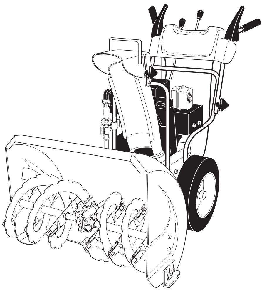
OWNER'S MANUAL
MODEL NUMBER:
961980018
SNOW THROWER
A WARNING:
Read the Owner's Manual and follow allWarnings and Safety Instructions. Failure to do so can result in serious injury.
IMPORTANT
Safe Operation Practices for Walk-Behind Snow Throwers
This snow thrower is capable of amputating hands and feet and throwing objects.
Failure to observe the following safety instructions could result in serious injury.

Look for this symbol to point out important safety precautions. It means CAUTION!!! BECOME ALERT!!! YOUR SAFETY IS INVOLVED.

WARNING: Always remove safety ignition key and disconnect spark plug wire and place it where it cannot contact plug in order to prevent accidental starting when setting up, transporting, adjusting or making repairs.

WARNING: This snow thrower is for use on sidewalks, driveways and other ground level surfaces. Caution should be exercised while using on sloping surfaces. Do not use snow thrower on surfaces above ground level such as roofs of residences, garages, porches or other such structures or buildings.

WARNING: Snow throwers have exposed rotating parts, which can cause severe injury from contact, or from material thrown from the discharge chute. Keep the area of operation clear of all persons, small children and pets at all times including startup.

CAUTION: Muffler and other engine parts become extremely hot during operation and remain hot after engine has stopped. To avoid severe burns on contact, stay away from these areas.

WARNING: Engine exhaust, some of its constituents, and certain vehicle components contain or emit chemicals known to the State of California to cause cancer and birth defects or other reproductive harm.
Training
- Read, understand and follow all instructions on the machine and in the manual(s) before operating this unit. Be thoroughly familiar with the controls and the proper use of the equipment. Know how to stop the unit and disengage the controls quickly.
- Never allow children to operate the equipment. Never allow adults to operate the equipment without proper instruction.
- Keep the area of operation clear of all persons, particularly small children.
- Exercise caution to avoid slipping or falling, especially when operating the snow thrower in reverse.
Preparation
- Thoroughly inspect the area where the equipment is to be used and remove all doormats, sleds, boards, wires, and other foreign objects.
- Disengage all clutches and shift into neutral before starting the engine (motor).
- Do not operate the equipment without wearing adequate winter garments. Avoid loose fitting clothing that can get caught in moving parts. Wear footwear that will improve footing on slippery surfaces.
- Handle fuel with care; it is highly flammable
(a) Use an approved fuel container.
(b) Never add fuel to a running engine or hot engine.
(c) Fill fuel tank outdoors with extreme care. Never fill fuel tank indoors.
(d) Never fill containers inside a vehicle or on a truck or trailer bed with a plastic liner. Always place containers on the ground, away from your vehicle, before filling.
(e) When practical, remove gas-powered equipment from the truck or trailer and refuel it on the ground. If this is not possible, then refuel such equipment on a trailer with a portable container, rather than from a gasoline dispenser nozzle.
(f) Keep the nozzle in contact with the rim of the fuel tank or container opening at all times, until refueling is complete. Do not use a nozzle lock-open device.
(g) Replace gasoline cap securely and wipe up spilled fuel.
(h) If fuel is spilled on clothing, change clothing immediately.
- Use extension cords and receptacles as specified by the manufacturer for all units with electric drive motors or electric starting motors.
- Adjust the collector housing height to clear gravel or crushed rock surface.
- Never attempt to make any adjustments while the engine (motor) is running (except when specifically recommended by manufacturer).
- Always wear safety glasses or eye shields during operation or while performing an adjustment or repair to protect eyes from foreign objects that may be thrown from the machine.
Operation
- Do not put hands or feet near or under rotating parts. Keep clear of the discharge opening at all times.
- Exercise extreme caution when operating on or crossing gravel drives, walks, or roads. Stay alert for hidden hazards or traffic.
- After striking a foreign object, stop the engine (motor), remove the wire from the spark plug, disconnect the cord on electric motors, thoroughly inspect the snow thrower for any damage, and repair the damage before restarting and operating the snow thrower.
- If the unit should start to vibrate abnormally, stop the engine (motor) and check immediately for the cause. Vibration is generally a warning of trouble.
-
Stop the engine (motor) whenever you leave the operating position, before unclogging the collector/impeller housing or discharge chute, and when making any repairs, adjustments or inspections.
-
When cleaning, repairing or inspecting the snow thrower, stop the engine and make certain the collector/impeller and all moving parts have stopped. Disconnect the spark plug wire and keep the wire away from the plug to prevent someone from accidentally starting the engine.
- Do not run the engine indoors, except when starting the engine and for transporting the snow thrower in or out of the building. Open the outside doors; exhaust fumes are dangerous.
- Exercise extreme caution when operating on slopes.
- Never operate the snow thrower without proper guards, and other safety protective devices in place and working.
- Never direct the discharge toward people or areas where property damage can occur. Keep children and others away.
- Do not overload the machine capacity by attempting to clear snow at too fast a rate.
- Never operate the machine at high transport speeds on slippery surfaces. Look behind and use care when operating in reverse.
- Disengage power to the collector/impeller when snow thrower is transported or not in use.
- Use only attachments and accessories approved by the manufacturer of the snow thrower (such as wheel weights, counterweights, or cabs).
-
Never operate the snow thrower without good visibility or light. Always be sure of your footing, and keep a firm hold on the handles. Walk; never run.
-
Never touch a hot engine or muffler.
Clearing a Clogged Discharge Chute
Hand contact with the rotating impeller inside the discharge chute is the most common cause of injury associated with snow throwers. Never use your hand to clean out the discharge chute. To clear the chute:
- SHUT THE ENGINE OFF!
- Wait 10 seconds to be sure the impeller blades have stopped rotating.
- Always use a clean-out tool, not your hands.
Maintenance and Storage
- Check shear bolts and other bolts at frequent intervals for proper tightness to be sure the equipment is in safe working condition.
- Never store the machine with fuel in the fuel tank inside a building where ignition sources are present such as hot water heaters, space heaters, or clothes dryers. Allow the engine to cool before storing in any enclosure.
- Always refer to operator's manual for important details if the snow thrower is to be stored for an extended period.
- Maintain or replace safety and instruction labels, as necessary.
- Run the machine a few minutes after throwing snow to prevent freeze-up of the collector/impeller.
CONGRATULATIONS on your purchase of a new snow thrower. It has been designed, engineered and manufactured to give best possible dependability and performance.
Should you experience any problem you cannot easily remedy, please contact your nearest authorized service center. We have competent, well-trained technicians and the proper tools to service or repair this unit.
Please read and retain this manual. The instructions will enable you to assemble and maintain your snow thrower properly. Always observe the "SAFETY RULES".
SERIAL NUMBER:
DATE OF PURCHASE:
THE MODEL AND SERIAL NUMBERS WILL BE FOUND ON A DECAL ATTACHED TO THE REAR OF THE SNOW THROWER HOUSING.
YOU SHOULD RECORD BOTH SERIAL NUMBER AND DATE OF PURCHASE AND KEEP IN A SAFE PLACE FOR FUTURE REFERENCE.
PRODUCT SPECIFICATIONS
| Gasoline Capacity and Type: | 4.0 Quarts Unleaded Regular only |
| Oil Type (API SG-SL): | SAE 30 (above 40°F) SAE 5W-30 or 10W-30 (0° to +40°F) SAE 0W-30 (below 0°F) |
| Oil Capacity: | 21 Ounces (0,6 Liters) |
| Spark Plug: | Champion RJ19LM |
| Gap: | 0.030" (0,762 mm) |
CUSTOMER RESPONSIBILITIES
- Read and observe the safety rules.
- Follow a regular schedule in maintaining, caring for and using your snow thrower.
- Follow the instructions under "Maintenance" and "Storage" sections of this owner's manual.
TABLE OF CONTENTS
SAFETY RULES 2-3
PRODUCT SPECIFICATIONS 3
CUSTOMER RESPONSIBILITIES 3
ASSEMBLY / PRE-OPERATION 4-6
OPERATION 7-12
MAINTENANCE 13-14
MAINTENANCE SCHEDULE 13
SERVICE AND ADJUSTMENTS 15-17
STORAGE 17
TROUBLESHOOTING 18
REPAIR PARTS 20-31
WARRANTY 32
PARTS PACKED SEPARATELY IN CARTON
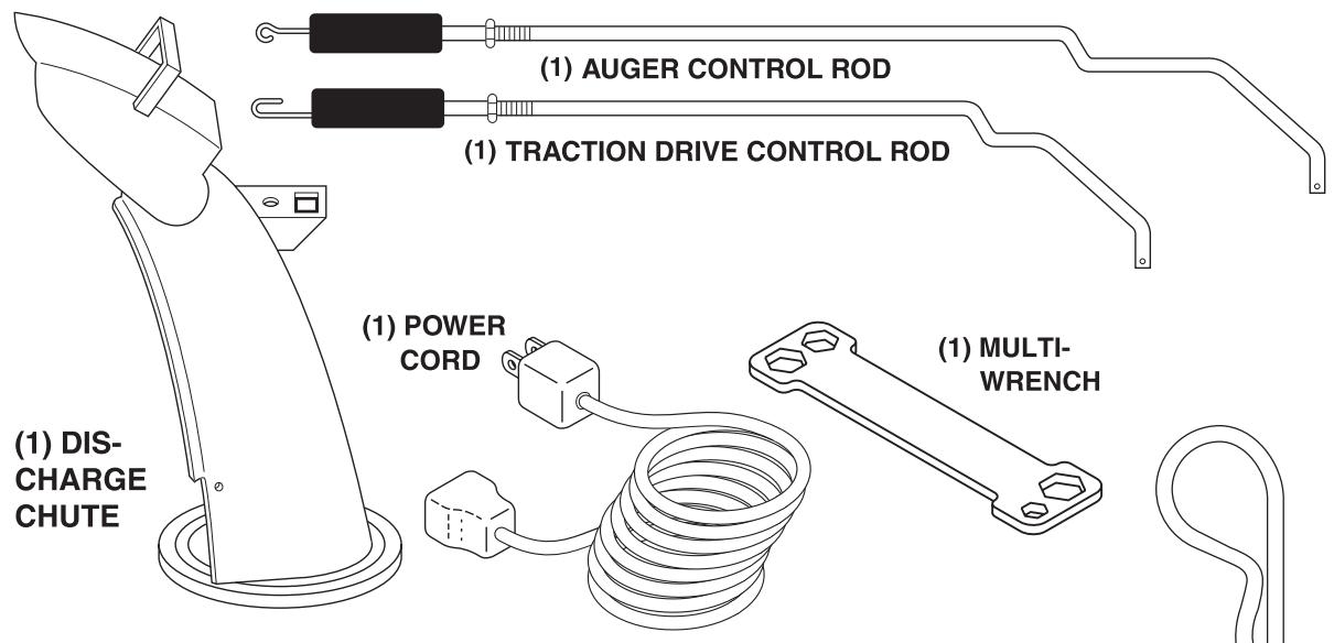
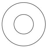
ROTATOR HEAD MOUNTING
(1) WASHER 3/8
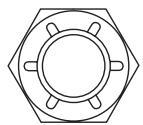
(1) LOCKNUT 3/8
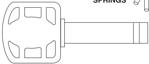
(2) SAFETY IGNITION KEYS
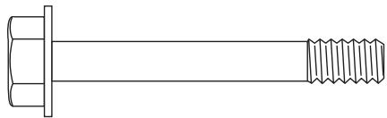
EXTRA SHEAR BOLTS AND NUTS
(2) SHEAR BOLTS 1/4-20 x 1-3/4

(2) SPACERS
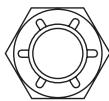
(2) LOCKNUTS 1/4-20
ASSEMBLY / PRE-OPERATION
Read these instructions and this manual in its entirety before you attempt to assemble or operate your new snow thrower. Reading the entire manual will familiarize you with the unit, which will assist you in assembly, operation and maintenance of the product.
Your new snow thrower has been assembled at the factory with the exception of those parts left unassembled for shipping purposes. All parts such as nuts, washers, bolts, etc., necessary to complete the assembly have been placed in the parts bag. To ensure safe and proper operation of your snow thrower, all parts and hardware you assemble must be tightened securely. Use the correct tools as necessary to ensure proper tightness.
REMOVE SNOW THROWER FROM CARTON
-
Remove all accessible loose parts and parts boxes from carton.
-
Cut down all four corners of carton and lay panels flat.
- Remove the two (2) screws securing the auger housing to the pallet.
- Remove all packing materials except plastic tie holding speed control rod to lower handle.
- Remove the two (2) plastic ties securing the upper handle to the pallet.
- Remove snow thrower from carton and check carton thoroughly for additional loose parts.
HOW TO SET UP YOUR SNOW THROWER
TOOL BOX (See Fig. 8)
A toolbox is provided on your snow thrower. The toolbox is located on top of the belt cover. Store the extra shear bolts, nuts and multi-wrench provided in parts bag in the toolbox.
ASSEMBLY / PRE-OPERATION
NOTE: The multi-wrench may be used for assembly of the chute rotator head to snow thrower and making adjustments to the skid plates.
UNFOLD UPPER HANDLE
- Raise upper handle to the operating position and tighten handle knobs securely.
INSTALL SPEED CONTROL ROD (See Figs. 1 and 2)
- Remove plastic tie securing rod to lower handle.
- Insert rod into speed control bracket and secure with retainer spring.
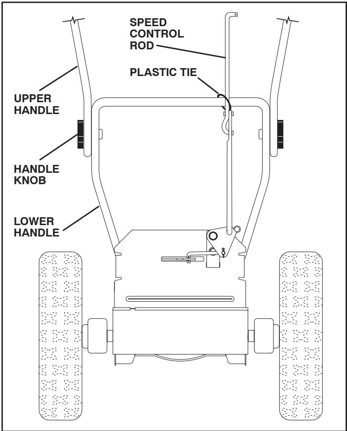
FIG. 1
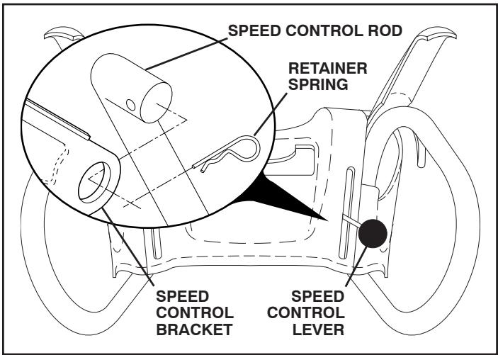
FIG.2
INSTALL TRACTION DRIVE CONTROL ROD (See Figs. 3 and 4)
The traction drive control rod has the long loop on the end of the spring as shown.
- Slide rubber sleeve up rod and hook end of spring into pivot bracket with loop opening down as shown.
- With top end of rod positioned under left side of control panel, push rod down and insert top end of rod into hole in drive control bracket. Secure with retainer spring.
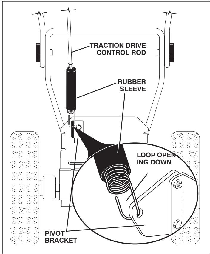
FIG. 3
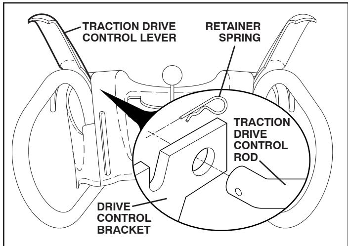
FIG. 4
ASSEMBLY / PRE-OPERATION
INSTALL AUGER CONTROL ROD (See Figs. 5 and 6)
The auger control rod has the short loop on the end of the spring as shown.
- Slide rubber sleeve up rod and hook end of spring into control arm with loop opening up as shown.
- With top end of rod positioned under right side of control panel, push down on rod and insert end of rod into hole in auger control bracket. Secure with retainer spring.
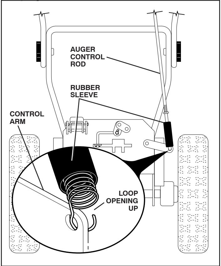
FIG. 5
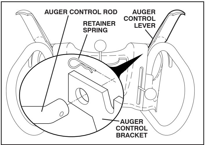
FIG. 6
INSTALL DISCHARGE CHUTE / CHUTE ROTATOR HEAD (See Fig. 7)
NOTE: The multi-wrench provided in your parts bag may be used to install the chute rotator head.
- Place discharge chute assembly on top of chute base with discharge opening toward front of snow thrower.
- Position chute rotator head over chute bracket. If necessary, rotate chute assembly to align square and pin on underside of chute rotator head with holes in chute bracket.
- With chute rotator head and chute bracket aligned, position chute rotator head on pin and threaded stud of mounting bracket.
- Install 3/8 washer and locknut on threaded stud and tighten securely.
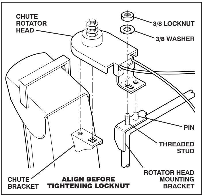
FIG. 7
CHECK TIRE PRESSURE
The tires on your snow thrower were overinflated at the factory for shipping purposes. Correct and equal tire pressure is important for best snow throwing performance.
- Reduce tire pressure to 14-17 PSI (19-24.5 N-m).
OPERATION
KNOW YOUR SNOW THROWER
READ THIS OWNER'S MANUAL AND ALL SAFETY RULES BEFORE OPERATING YOUR SNOW THROWER. Compare the illustrations with your snow thrower to familiarize yourself with the location of various controls and adjustments. Save this manual for future reference.
These symbols may appear on your snow thrower or in literature supplied with the product. Learn and understand their meaning.

DANGER OR WARNING
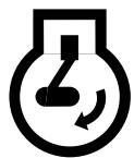
ENGINE ON

ENGINE OFF
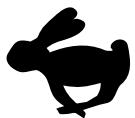
FAST

SLOW
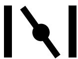
CHOKE

PRIMER
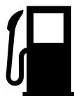
FUEL

OIL

FORWARD

REVERSE

READ AND FOLLOW ALL SAFETY INFORMATION AND INSTRUCTIONS BEFORE USE OF THIS PRODUCT. KEEP THESE INSTRUCTIONS FOR FUTURE REFERENCE.
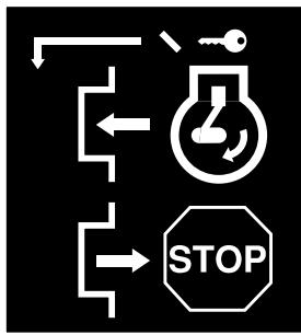
IGNITION KEY. INSERT TO START AND RUN, PULL OUT TO STOP.

DANGER

TO AVOID INJURY FROM ROTATING AUGER - KEEP HANDS,FEET AND CLOTHING AWAY.
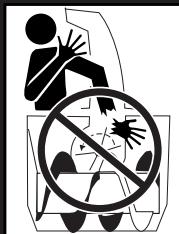
DANGER
BLOCKAGES MUST NOT BE CLEARED OUT UNTIL THE ENGINE IS SHUT OFF, AND THE CLEAN OUT TOOL MUST BE USED. NEVER USE YOUR HAND TO CLEAN OUT THE CHUTE.
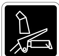
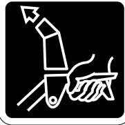
ENGAGED
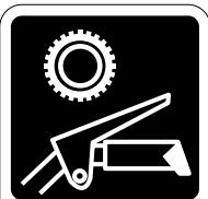
DISENGAGED
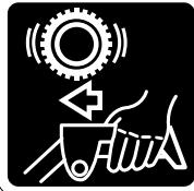
TRACTION DRIVE CONTROL
DANGER

- READ AND FOLLOW OWNER'S MANUAL
- NEVER ALLOW CHILDREN TO OPERATE SNOWTHROWERS.
- KEEP ALL SHIELDS AND GUARDS IN PLACE WHILE OPERATING.

- SHUT OFF ENGINE AND REMAIN BEHIND HANDLES UNTIL ALL MOVING PARTS HAVE STOPPED BEFORE UNCLOGGING OR SERVICING UNIT.

- TO AVOID THROWN OBJECT INJURIES NEVER DIRECT DISCHARGE AT BYSTANDERS. USE EXTRA CAUTION WHEN OPERATING ON GRAVEL SURFACES.
OPERATION
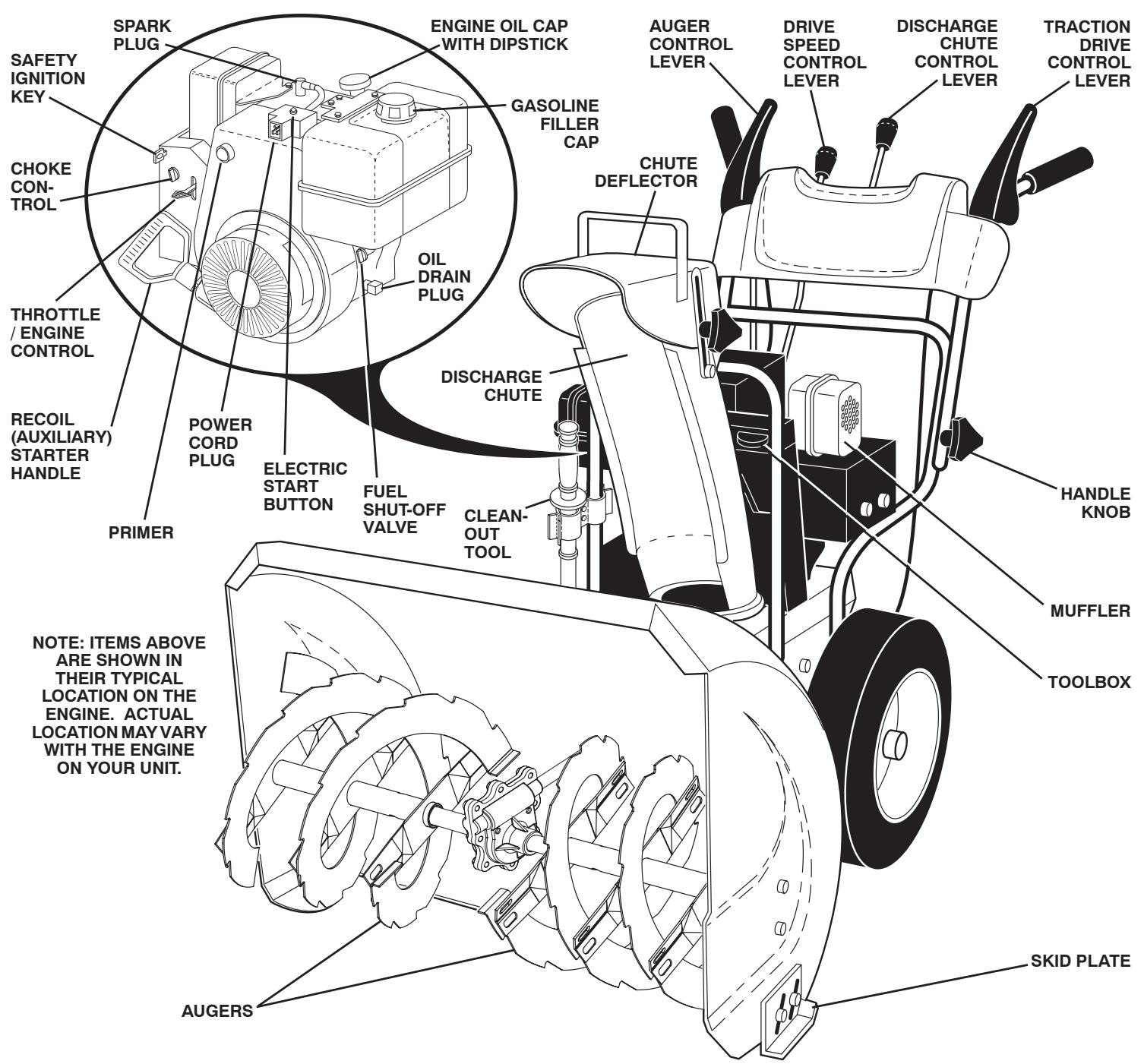
FIG. 8
MEETS A.N.S.I. SAFETY REQUIREMENTS
Our snow throwers conform to the standards of the American National Standards Institute.
Toolbox - used to store spare shear bolts, locknuts and wrench.
Safety ignition key - must be inserted for the engine to start and run. Remove when snow thrower is not in use.
Electric start button - used for starting the engine.
Recoil (auxiliary) starter handle - used for starting the engine.
Primer - pumps additional fuel from the carburetor to the cylinder for use when starting a cold engine.
Choke control - used for starting a cold engine.
Throttle/engine control - used to select either FAST or SLOW engine speed and to STOP the engine.
Traction drive control lever - used to engage power-propelled forward or reverse motion of snow thrower.
Auger control lever - used to engage auger motion (throw snow).
Discharge chute control lever - used to change the direction the snow is thrown.
Skid plate - used to adjust height of scraper bar from the ground.

The operation of any snow thrower can result in foreign objects thrown into the eyes, which can result in severe eye damage. Always wear safety glasses or eye shields while operating your snow thrower or performing any adjust-
ments or repairs. We recommend standard safety glasses or a wide vision safety mask worn over spectacles.
HOW TO USE YOUR SNOW THROWER
Know how to operate all controls before adding fuel or attempting to start the engine.
STOPPING
TRACTION DRIVE
- Release traction drive control lever to stop the forward or reverse movement of the snow thrower.
AUGER
- Release the auger control lever to stop throwing snow.
ENGINE
- Move throttle control to "STOP" position.
- Remove (do not turn) safety ignition key to prevent unauthorized use.
NOTE: Never use choke to stop engine.
TO USE FUEL SHUT-OFF VALVE (See Fig. 9)
The fuel shut-off valve is located beneath the fuel tank on the engine. Always operate the snow thrower with the fuel shut-off valve in the OPEN position.
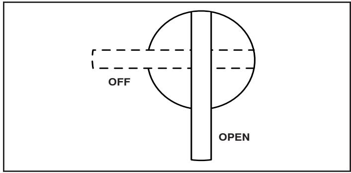
FIG. 9
TO USE THROTTLE CONTROL (See Fig. 10)
The throttle control is located on the engine. Always operate the snow thrower with the engine at full throttle. Full throttle offers the best snow thrower performance.
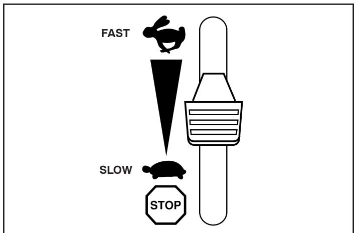
FIG. 10
TO USE CHOKE CONTROL (See Fig. 11)
The choke control is located on the engine. Use the choke control whenever you are starting a cold engine. Do not use to start a warm engine.
- To engage choke, turn knob clockwise. Slowly turn knob counterclockwise to disengage.
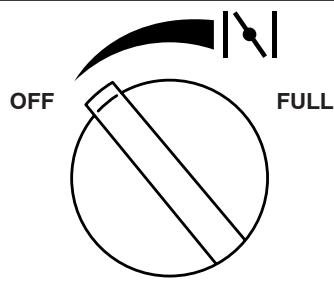
FIG. 11
TO CONTROL SNOW DISCHARGE (See Figs. 12 & 13)

WARNING: Snow throwers have exposed rotating parts, which can cause severe injury from contact, or from material thrown from the discharge chute. Keep the area of operation clear of all persons, small children and pets at all times including startup.

WARNING: If the discharge chute or auger become clogged, shut-off engine and wait for all moving parts to stop. Use the clean-out tool, NOT YOUR HANDS, to unclog the chute and/or auger.
The DIRECTION in which snow is to be thrown is controlled by the discharge chute control lever.
- To change the discharge chute position, press downward on discharge chute control lever and move lever left or right until chute is in desired position. Be sure lever springs back and locks into desired position.
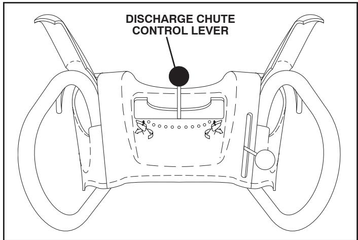
FIG. 12
The DISTANCE that snow is thrown is controlled by the position of the chute deflector. Set the deflector low to throw snow a short distance; set the deflector higher to throw snow farther.
- To change the deflector position, loosen knob, move deflector to desired position and tighten knob securely.
OPERATION
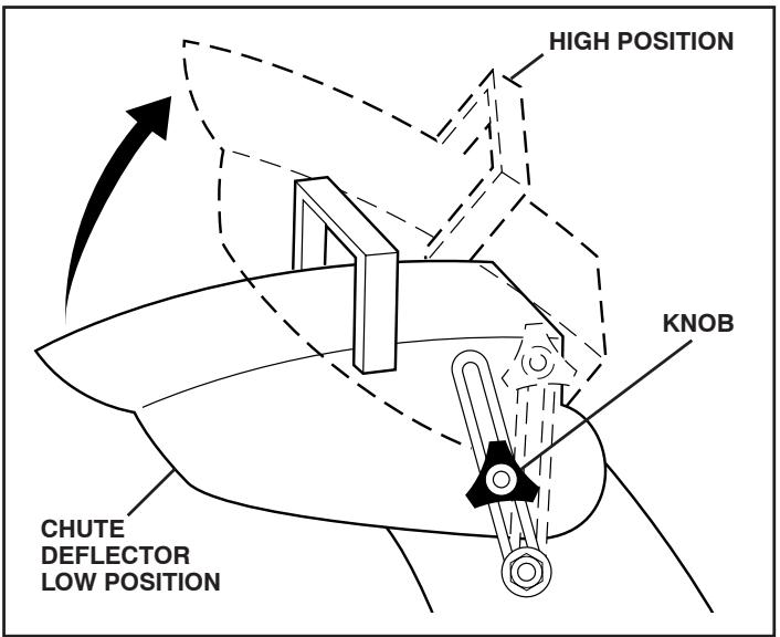
FIG. 13
TO THROW SNOW (See Fig. 14)
The auger rotation is controlled by the auger control lever located on the right side handle.
- Squeeze auger control lever to handle to engage the auger and throw snow.
- Release the auger control lever to stop throwing snow.
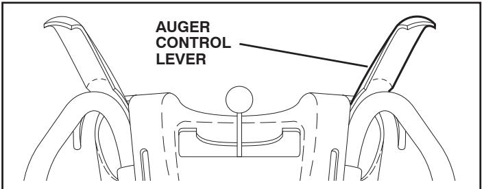
FIG. 14
USING THE CLEAN-OUT TOOL (See Fig. 15)
In certain snow conditions, the discharge chute may become clogged with ice and snow. Use the clean-out tool to dislodge this blockage.
When cleaning, repairing, or inspecting, make certain all controls are disengaged and the auger/impeller and all moving parts have stopped. Disconnect the spark plug wire and keep the wire away from the spark plug to prevent accidental starting.
- Release the auger control lever and shut off the engine.
- Remove the clean-out tool from it's mounting clip. Grasp the tool firmly by the handle and push and twist the tool into the discharge chute to dislodge the blockage.
After the packed snow has been dislodged, return the clean-out tool to it's mounting clip by pushing it into the clip.
- Make sure the discharge chute is pointed in a safe direction (no vehicles, buildings, people, or other objects are in the direction of discharge) before restarting the engine.
- Restart the engine, then squeeze the auger control lever to the handle to clear snow from the auger housing and the discharge chute.
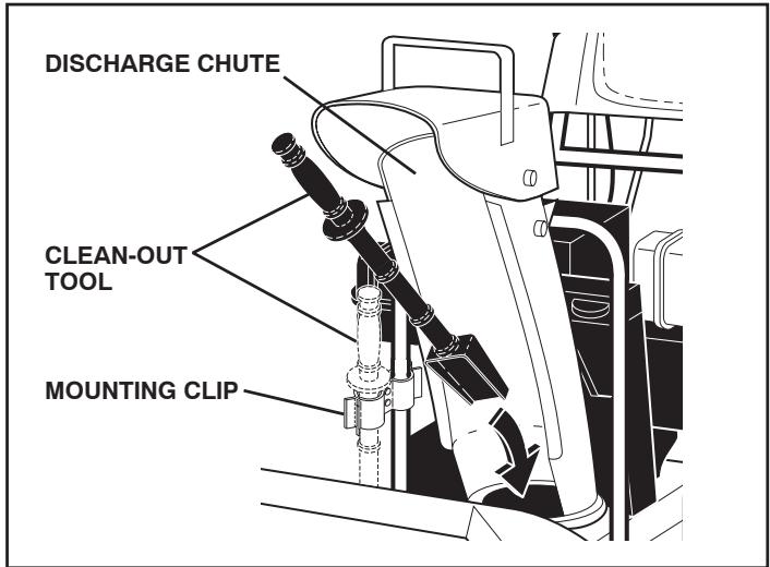
FIG. 15
TO MOVE FORWARD AND BACKWARD (See Fig. 16)
SELF-PROPELLING, forward and reverse movement of the snow thrower, is controlled by the traction drive control lever located on the left side handle.
- Squeeze traction drive control lever to handle to engage the drive system.
- Release traction drive control lever to stop the forward or reverse movement of the snow thrower.
SPEED and DIRECTION are controlled by the drive speed control lever.
- Press downward on the speed control lever and move lever to desired position BEFORE engaging the traction drive control lever. Be sure lever springs back and locks into desired position.
CAUTION: Do not move speed control lever when traction drive control lever is engaged. Damage to the snow thrower can result.
- Slower speeds are for heavier snow and faster speeds are for light snow and transporting the snow thrower. It is recommended that you use a slower speed until you are familiar with the operation of the snow thrower.
NOTE: When both traction drive and auger control levers are engaged, the traction drive control lever will lock the auger control lever in the engaged position. This will allow you to release your right hand from the handle and adjust the discharge chute direction without interrupting the snow throwing process.
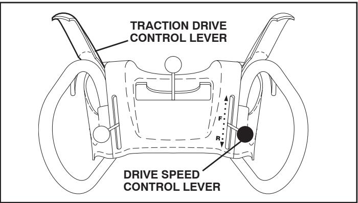
FIG. 16
TO ADJUST SKID PLATES (See Fig. 17)
NOTE: The wrench provided in your parts bag may be used to adjust the skid plates.
Skid plates are located on each side of the auger housing and adjust the clearance between the scraper bar and the ground surface. Adjust skid plates evenly to proper height for current surface conditions. For removal of snow in normal conditions, such as a paved driveway or sidewalk, place skid plates in the highest position (lowest scraper clearance) to give a 1/8 clearance between the scraper bar and the ground. Use a middle position if the surface to be cleared is uneven.
NOTE: It is not recommended to operate the snow thrower over gravel or rocky surfaces. Objects such as gravel, rocks, or other debris, can easily be picked up and thrown by the impeller, which can cause serious personal injury, property damage or damage to the snow thrower.
- If snow thrower must be operated over gravel surface, use extra caution and be sure skid plates are adjusted to lowest (highest scraper clearance) position.
- Shut off engine and wait for all moving parts to stop.
- Adjust skid plates by loosening the hex nuts, then moving skid plate to desired position. Be sure both plates are adjusted evenly. Tighten securely.
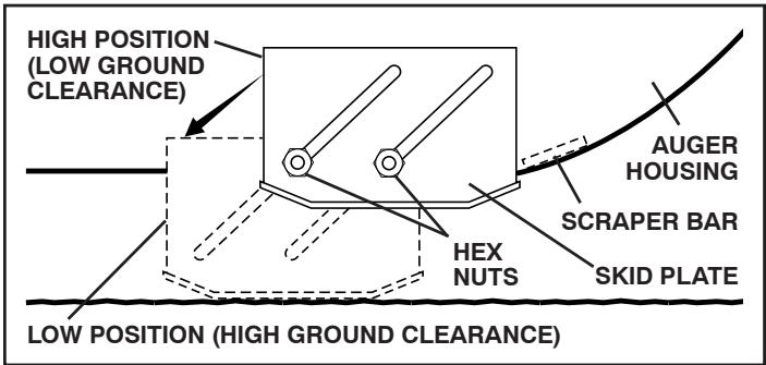
FIG. 17
SCRAPER BAR
The scraper bar is not adjustable, but is reversible. After considerable use it may become worn. When it has worn almost to the edge of the housing, it can be reversed, providing additional service before requiring replacement. Replace a damaged or worn scraper bar.
BEFORE STARTING THE ENGINE
CHECK ENGINE OIL LEVEL (See Fig. 18)
The engine on your snow thrower has been shipped, from the factory, already filled with oil.
- Check engine oil with snow thrower on level ground.
- Remove oil fill cap/dipstick and wipe clean, reinsert the dipstick and screw tight, wait for a few seconds, remove and read oil level. If necessary, add oil until "FULL" mark on dipstick is reached. Do not overfill.
- To change engine oil, see "TO CHANGE ENGINE OIL" in the Maintenance section of this manual.
ADD GASOLINE (See Fig. 18)
- Fill fuel tank to bottom of tank filler neck. Do not overfill. Use fresh, clean, regular unleaded gasoline with a minimum of 87 octane. Do not mix oil with gasoline. Purchase fuel in quantities that can be used within 30 days to assure fuel freshness.

WARNING: Wipe off any spilled oil or fuel. Do not store, spill or use gasoline near an open flame.
CAUTION: Alcohol blended fuels (called gasohol or using ethanol or methanol) can attract moisture which leads to separation and formation of acids during storage. Acidic gas can damage the fuel system of an engine while in storage. To avoid engine problems, the fuel system should be emptied before storage of 30 days or longer. Drain the gas tank, start the engine and let it run until the fuel lines and carburetor are empty. Use fresh fuel next season. See Storage Instructions for additional information. Never use engine or carburetor cleaner products in the fuel tank or permanent damage may occur.
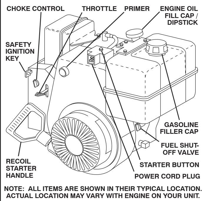
FIG. 18
TO START ENGINE
- Be sure fuel shut-off valve is in the OPEN position.
Your snow thrower engine is equipped with both a 120 Volt A.C. electric starter and a recoil starter. The electric starter is equipped with a three-wire power cord and plug and is designed to operate on 120 Volt A.C. household current.
- Be sure your house is a 120 Volt A.C. three-wire grounded system. If you are uncertain, consult a licensed electrician.

WARNING: Do not use the electric starter if your house is not a 120 Volt A.C. three-wire grounded system. Serious personal injury or damage to your snow thrower could result.
OPERATION
COLD START - ELECTRIC STARTER
- Insert safety ignition key (packed separately in parts bag) into ignition slot until it clicks. DO NOT turn the key. Keep the extra safety ignition key in a safe place.
- Place throttle control in FAST position.
- Rotate choke control to FULL position.
- Connect the power cord to the engine.
- Plug the other end of the power cord into a three-hole grounded 120 Volt A.C. receptacle.
- Push the primer three (3) times.
- Push starter button until engine starts.
IMPORTANT: Do not crank engine more than five continuous seconds between each time you try to start. Wait 5 to 10 seconds between each attempt.
- When the engine starts, release the starter button and slowly move the choke control to the "OFF" position.
- Disconnect the power cord from the receptacle first, then from the engine.
Allow the engine to warm up for a few minutes. Engine will not develop full power until it has reached normal operating temperature.
WARM START - ELECTRIC STARTER
Follow the steps above, keeping the choke control in the OFF position.
COLD START - RECOIL STARTER
- Insert safety ignition key (packed separately in parts bag) into ignition slot until it clicks. DO NOT turn the key. Keep the extra safety ignition key in a safe place.
- Place throttle control in FAST position.
- Rotate choke control to FULL position.
- Push the primer four (4) times if the temperature is below 15°F , or two (2) times if temperature is between 15° and 50°F . If temperature is above 50°F , priming is not necessary.
NOTE: Over priming may cause flooding, preventing the engine from starting. If you do flood the engine, wait a few minutes before attempting to start and DO NOT push the primer.
- Pull recoil starter handle quickly. Do not allow starter rope to snap back.
- When the engine starts, release the recoil starter handle and slowly move the choke control to the OFF position.
Allow the engine to warm up for a few minutes. Engine will not develop full power until it has reached normal operating temperature.
WARM START - RECOIL STARTER
Follow the steps above, keeping the choke in the OFF position. DO NOT push the primer.
BEFORE STOPPING
Run the engine for a few minutes to help dry off any moisture on the engine.
IF RECOIL STARTER HAS FROZEN
If the recoil starter has frozen and will not turn the engine, proceed as follows:
- Grasp the recoil starter handle and slowly pull as much rope out of the starter as possible.
- Release the recoil starter handle and let it snap back against the starter.
If the engine still fails to start, repeat the above steps or use the electric starter.
SNOW THROWING TIPS
Always operate the snow thrower with the engine at full throttle. Full throttle offers the best performance.
- Go slower in deep, freezing or heavy wet snow. Use the drive speed control, NOT the throttle, to adjust speed.
It is easier and more efficient to remove snow immediately after it falls.
- The best time to remove snow is the early morning. At this time the snow is usually dry and has not been exposed to the direct sun and warming temperatures.
- Slightly overlap each successive path to ensure all snow will be removed.
- Throw snow downwind whenever possible.
- Adjust the skid plates to proper height for current snow conditions. See "TO ADJUST SKID PLATES" in this section of this manual.
- For extremely heavy snow, reduce the width of snow removal by overlapping previous path and moving slowly.
- Keep engine clean and clear of snow during use. This will help air flow and extend engine life.
After snow-throwing is completed, allow engine to run for a few minutes to melt snow and ice off the engine.
- Clean the entire snow thrower thoroughly after each use and wipe dry so it is ready for next use.

WARNING: Do not operate snow thrower if weather conditions impair visibility. Throwing snow during a heavy, windy snowstorm can blind you and be hazardous to the safe operation of the snow thrower.
MAINTENANCE
| MAINTENANCE SCHEDULE FILL IN DATES AS YOU COMPLETE REGULAR SERVICE | |||||||||||
| THROwER | Check for Loose Fasteners | ✓ | ✓ | ||||||||
| Clean / Inspect Snow Thrower | ✓ | ✓ | |||||||||
| Check / Replace V-Belts | ✓ | ||||||||||
| Lubrication Chart | ✓ | ✓ | |||||||||
| ENGINE | Check Engine Oil Level | ✓ | |||||||||
| Change Engine Oil | ✓ | ||||||||||
| Inspect Muffler | ✓ | ||||||||||
| Check / Replace Spark Plug | ✓ | ||||||||||
| Empty Fuel Tank | ✓ | ||||||||||
GENERAL RECOMMENDATIONS
The warranty on this snow thrower does not cover items that have been subjected to operator abuse or negligence. To receive full value from the warranty, operator must maintain snow thrower as instructed in this manual. Some adjustments will need to be made periodically to properly maintain your snow thrower. All adjustments in the Service and Adjustments section of this manual should be checked at least once each season.
- Once a year, you should replace the spark plug and check belts for wear. A new spark plug will help your engine run better and last longer.
- Follow the maintenance schedule in this manual.
NOTE: Use only Original Equipment Manufacturer (OEM) parts to service this unit. Failure to do so can cause the unit to malfunction and pose a risk of injury to the operator.
BEFORE EACH USE
- Check engine oil level.
- Check for loose fasteners.
- Check controls to be sure they are functioning properly.
LUBRICATION
Keep your snow thrower well lubricated (See "LUBRICATION CHART").
SNOW THROWER
Always observe the safety rules when performing any maintenance.
TIRES
- Maintain proper air pressure in both tires (14-17 P.S.I. / 19-24.5 N-m).
- Keep tires free of gasoline and oil, which can harm rubber.
NOTE: To seal tire punctures and prevent flat tires due to slow leaks, tire sealant may be purchased from your local parts dealer. Tire sealant also prevents tire dry rot and corrosion.
LUBRICATION CHART
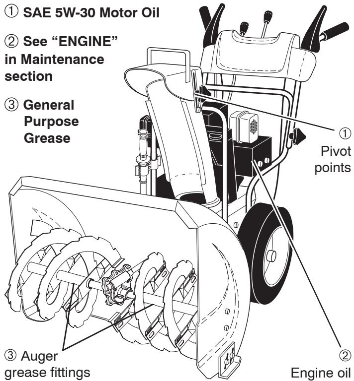
V-BELTS
Check V-belts for deterioration and wear after every 50 hours of operation and replace if necessary. The belts are not adjustable. Replace belts if they begin to slip from wear. (See "TO REMOVE BELT COVER" in the Service and Adjustments section of this manual).
The V-belts on your snow thrower are of special construction and should be replaced by original equipment manufacturer (OEM) belts available from your nearest dealer. Using other than OEM belts can cause personal injury or damage to the snow thrower.
MAINTENANCE
AUGER GEAR CASE
- The gear case was filled with lubricant to the proper level at the factory. The only time the lubricant needs attention is if service has been performed on the gear case.
- If lubricant is required, use only Ronex ED #1 grease.
TRACTION DRIVE SYSTEM
DO NOT lubricate the drive components inside the snow thrower. The sprockets, hex shafts, drive disc and friction wheel require no lubrication. The bearings and bushings are lifetime lubricated and require no maintenance.
CAUTION: Any lubricating of the above components can cause contamination of the friction wheel and damage to the drive system of your snow thrower.
ENGINE
See engine manual.
LUBRICATION
Use only high quality detergent oil rated with API service classification SG-SL. Select the oil's SAE viscosity grade according to your expected operating temperature.
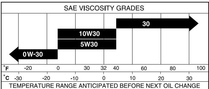
NOTE: Although multi-viscosity oils (5W30, 10W30 etc.) improve starting in cold weather, these multi-viscosity oils will result in increased oil consumption when used above 32°F . Check your engine oil level more frequently to avoid possible engine damage from running low on oil.
Change the oil after every 25 hours of operation or at least once a year if the snow thrower is not used for 25 hours in one year.
Check the crankcase oil level before starting the engine and after each five (5) hours of continuous use. Tighten oil fill cap / dipstick securely each time you check the oil level.
TO CHANGE ENGINE OIL
Determine temperature range anticipated before next oil change. All oil must meet API service classification SG-SL.
- Be sure snow thrower is on level surface.
Oil will drain more freely when warm.
Catch oil in a suitable container.
NOTE: The left side wheel may be removed from snow thrower for easier access to the oil drain plug and placement of a suitable container. The unit tilted, resting on the frame with the left wheel removed, will help drain any oil trapped inside the engine. (See "TO REMOVE WHEELS" in the Service and Adjustments section of this manual).
- Remove safety ignition key and disconnect spark plug wire from spark plug. Place wire where it cannot come in contact with plug.
- Clean area around drain plug.
- Remove drain plug and drain oil in a suitable container.
- Install drain plug and tighten securely.
- Wipe off any spilled oil from snow thrower and engine.
- Install left wheel (if removed for draining oil). Be sure to install klick pin into proper hole in wheel axle (See "TO REMOVE WHEELS" in the Service and Adjustments section of this manual).
- Remove oil fill cap/dipstick. Be careful not to allow dirt to enter the engine.
- Refill engine with oil through oil dipstick tube. Pour slowly. Do not overfill. For approximate capacity see "PRODUCT SPECIFICATIONS" section of this manual.
- Use gauge on oil fill cap/dipstick for checking level. Be sure dipstick cap is tightened securely for accurate reading. Keep oil at "FULL" line on dipstick.
- Wipe off any spilled oil.
MUFFLER
Inspect and replace corroded muffler as it could create a fire hazard and/or damage.
SPARK PLUG
Replace spark plug at the beginning of each season or after every 100 hours of operation, whichever occurs first. Spark plug type and gap setting are shown in the "PRODUCT SPECIFICATIONS" section of this manual.
CLEANING
IMPORTANT: For best performance, keep snow thrower housing free of any dirt or trash. Clean the outside of your snow thrower after each use.

WARNING: Remove safety ignition key and disconnect spark plug wire from spark plug. Place wire where it cannot come in contact with plug.
- Keep finished surfaces/wheels free of gasoline, oil, etc.
- We do not recommend using a garden hose to clean your snow thrower unless the electrical system, muffler and carburetor are covered to keep water out. Water in engine can result in shortened engine life.
SERVICE AND ADJUSTMENTS
WARNING: To avoid serious injury, before performing any service or adjustments:
- Be sure throttle is in STOP position.
- Remove safety ignition key.
- Make sure the augers and all moving parts have completely stopped.
- Remove safety ignition key and disconnect spark plug wire from spark plug. Place wire where it cannot contact plug.
SNOW THROWER
TO ADJUST SNOW THROWER HEIGHT
See "TO ADJUST SKID PLATES" and "SCRAPER BAR" in the Operation section of this manual.
CHUTE DEFLECTOR
The chute deflector, attached to the top of the discharge chute, is provided to direct discharging snow away from the operator. If the deflector becomes damaged, it should be replaced.

WARNING: To avoid serious injury, never operate your snow thrower with the deflector removed or damaged.
- To change direction and/or distance snow is discharged, see "TO CONTROL SNOW DISCHARGE" in the Operation section of this manual.
SHEAR BOLTS (See Fig. 19)
AUGER SHEAR BOLTS
Both right and left-hand augers are secured to the auger shaft with a shoulder/shear bolt and hex nut. Should a foreign object or ice become lodged in the augers, the shear bolts are designed to break, preventing damage to any other components. If one or both augers do not turn when auger control lever is engaged, check to see if one or both of the bolts have sheared. To replace the shear bolts:
- Disengage all controls and move throttle control to STOP position. Wait for all moving parts to stop.
- Remove safety ignition key and disconnect spark plug wire from spark plug. Place wire where it cannot come in contact with plug.
- Align hole in auger hub with hole in auger shaft and install a new 1/4 - 20 × 2 shoulder/shear bolt and spacer. Install 1/4-20 lock nut and tighten securely.
CAUTION: Do not substitute. Use only original equipment shear bolts as supplied with your snow thrower.
- Connect spark plug wire to spark plug. Replace safety ignition key.
IMPELLER SHEAR BOLTS
The impeller is secured to the impeller shaft with two (2) capscrew/shear bolts and hex nuts. Should a foreign object or ice become lodged in the impeller, the capscrews are designed to break, preventing damage to any other components. If impeller does not turn when auger control lever is engaged, check to see if the capscrews have sheared. To replace the capscrew/shear bolts:
- Disengage all controls and move throttle control to STOP position. Wait for all moving parts to stop.
- Remove safety ignition key and disconnect spark plug wire from spark plug. Place wire where it cannot come in contact with plug.
- Align holes in impeller hub with holes in impeller shaft and install two (2) new 1/4 - 20 × 1 - 5/8 capscrew/shear bolts. Install 1/4-20 locknuts and tighten securely.
CAUTION: Do not substitute. Use only original equipment capscrew/shear bolts as supplied with your snow thrower.
- Connect spark plug wire to spark plug. Replace safety ignition key.
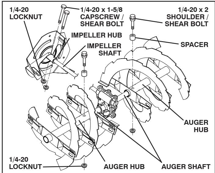
FIG. 19
TO REMOVE BELT COVER (See Fig. 20)
- Remove the two screws securing belt cover to frame.
- Remove belt cover.
- Replace belt cover by installing cover and screws and tighten securely.
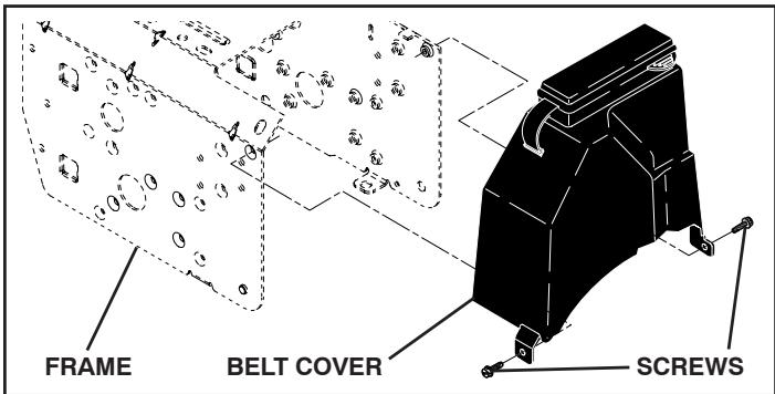
FIG. 20
TO REPLACE BELTS (See Fig. 21)
The auger and traction drive belts are not adjustable. If the belts are damaged or begin to slip from wear, they should be replaced. It is recommended that the belt(s) be replaced by a qualified service center.
NOTE: It is recommended that both the auger and traction drive belt be replaced at the same time.
The V-belts on your snow thrower are of special construction and should be replaced by original equipment manufacturer (OEM) belts available from your nearest dealer. Using other than OEM belts can cause personal injury or damage to the snow thrower.
SERVICE AND ADJUSTMENTS

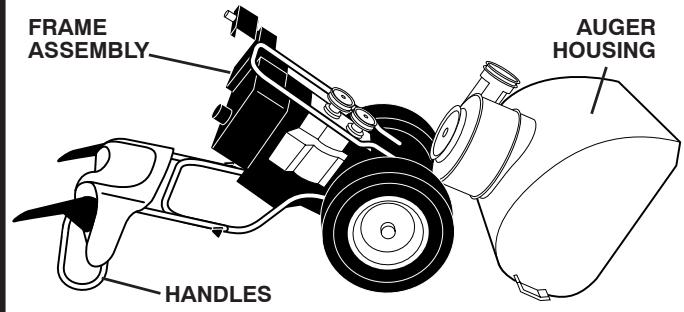
WARNING: Belt replacement requires separation of the snow thrower. While separating the auger housing from the frame assembly, it is important that an assistant stand in the operating position and hold the snow thrower handles. Serious personal injury and/or damage to the unit could occur if the snow thrower should fall during the belt changing process.
- REMOVE GASOLINE FROM FUEL TANK - Drain gasoline from fuel tank into a suitable container, outdoors, away from fire or flame. Wipe up any spilled gasoline.
- REMOVE DISCHARGE CHUTE - Loosen locknut securing chute rotator head to mounting bracket only enough to allow chute rotator head to be raised and discharge chute to be removed from snow thrower.
- REMOVE BELT COVER - See "TO REMOVE BELT COVER" in this section of this manual.
- REMOVE ENGINE PULLEY - Remove bolt, lockwasher and flat washer securing pulley to engine crankshaft. Remove outside (auger) pulley only from crankshaft.
- SEPARATE SNOW THROWER - With your assistant standing in the operating position holding the handles, remove the two (2) bolts holding auger housing and frame together.

WARNING: As the last bolt is removed, have your assistant carefully lower the handles down to the ground.
- REMOVE AUGER BELT from around pulley.
- RELIEVETENSIONNONTRACTIONDRIVEBELTIDLER and remove traction drive belt from around pulleys.
HINT: Insert a 3/8 drive ratchet (in the "ON" position) into the square hole in idler arm and rotate ratchet clockwise to relieve tension.
- With tension relieved on idler, install new traction drive belt around pulleys and inside belt keepers.
- Place auger belt around and inside the groove of auger pulley only.
- While your assistant slowly raises handles to rejoin the auger housing and frame assembly, pull up on the auger belt and squeeze sides together above pulley so belt is fully seated in groove of pulley.
-
Bring snow thrower completely together and check carefully for proper routing of belts. If auger belt has become dislodged from the pulley (by catching the idler arm bracket while bringing snow thrower together), separate the snow thrower and repeat step 10. Belt must be fully seated in pulley groove when bringing the snow thrower together.
-
Install the two (2) hex bolts and tighten securely.
- INSTALL ENGINE PULLEY - Place belt in pulley groove and slide pulley on crankshaft. Install flat washer, lockwasher and bolt and tighten securely (30-35 ft. lbs. torque). Make sure belt is inside belt keeper.
- INSTALL BELT COVER and two (2) screws. Tighten securely.
- INSTALL DISCHARGE CHUTE – See “INSTALL DISCHARGE CHUTE / CHUTE ROTATER HEAD” in the Assembly / Pre-Operation section of this manual.
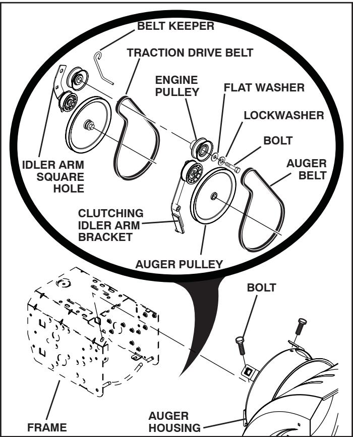
FIG. 21
TO REMOVE WHEELS (See Fig. 22)
- Remove the klik pin and remove wheel from axle.
IMPORTANT: When installing wheel, be sure to use the innermost hole in axle and the wheel hub hole. To disengage drive system from the wheels (for pushing or transporting the snow thrower), remove klik pin from wheel hub and insert pin into the outermost hole in axle only.
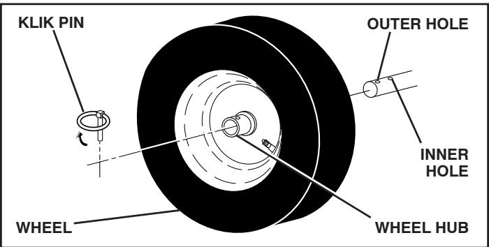
FIG. 22
SERVICE AND ADJUSTMENTS
NOTE: To seal punctures or prevent flat tires due to slow leaks, tire sealant may be purchased from your local parts dealer. Tire sealant also prevents tire dry rot and corrosion.
ENGINE
See engine manual.
CARBURETOR
Your carburetor is not adjustable. Engine performance should not be affected at altitudes up to 7,000 feet (2,134 meters). If your engine does not operate properly due to suspected carburetor problems, take your snow thrower to a qualified service center.
ENGINE SPEED
Never tamper with the engine governor, which is factory set for proper engine speed. Overspeeding the engine above the factory high speed setting can be dangerous and will void the warranty. If you think the engine-governed high speed needs adjusting, contact a qualified service center, which has proper equipment and experience to make any necessary adjustments.
STORAGE
Immediately prepare your unit for storage at the end of the season or if the unit will not be used for 30 days or more.

WARNING: Never store the snow thrower with gasoline in the tank inside a building where fumes may reach an open flame, spark or pilot light as on a furnace, water heater, clothes dryer or gas appliance. Allow the engine to cool before storing in any enclosure.
SNOW THROWER
When snow thrower is to be stored for a period of time, clean it thoroughly, remove all dirt, grease, leaves, etc. Store in a clean, dry area.
- Clean entire snow thrower (See "CLEANING" in the Maintenance section of this manual).
- Inspect and replace belts, if necessary (See "TO REPLACE BELTS" in the Service and Adjustments section of this manual).
- Lubricate as shown in the Maintenance section of this manual.
- Be sure that all nuts, bolts, screws, and pins are securely fastened. Inspect moving parts for damage, breakage and wear. Replace if necessary.
- Touch up all rusted or chipped paint surfaces; sand lightly before painting.
ENGINE
See engine manual.
FUEL SYSTEM
IMPORTANT: It is important to prevent gum deposits from forming in essential fuel system parts such as carburetor, fuel hose, or tank during storage. Also, alcohol blended fuels (called gasohol or using ethanol or methanol) can attract moisture which leads to separation and formation of acids during storage. Acidic gas can damage the fuel system of an engine while in storage.
- Empty the fuel tank by starting the engine and letting it run until the fuel lines and carburetor are empty.
- Never use engine or carburetor cleaner products in the fuel tank or permanent damage may occur.
Use fresh fuel next season.
NOTE: Fuel stabilizer is an acceptable alternative in minimizing the formation of fuel gum deposits during storage. Add stabilizer to gasoline in fuel tank or storage container. Always follow the mix ratio found on stabilizer container. Run engine at least 10 minutes after adding stabilizer to allow the stabilizer to reach the carburetor. Do not drain the gas tank and carburetor if using fuel stabilizer.
ENGINE OIL
Drain oil (with engine warm) and replace with clean engine oil. (See "ENGINE" in the Maintenance section of this manual).
CYLINDER
- Remove spark plug.
- Pour one ounce (29 ml) of oil through spark plug hole into cylinder.
- Pull recoil starter handle slowly a few times to distribute oil.
- Replace with new spark plug.
OTHER
- Remove safety ignition key; store it in a safe place.
- Do not store gasoline from one season to another.
- Replace your gasoline can if your can starts to rust. Rust and/or dirt in your gasoline will cause problems.
If possible, store your snow thrower indoors and cover it to protect it from dust and dirt. - Cover your snow thrower with a suitable protective cover that does not retain moisture. Do not use plastic. Plastic cannot breathe, which allows condensation to form and will cause your snow thrower to rust.
IMPORTANT: Never cover snow thrower while engine/exhaust area is still warm.
TROUBLESHOOTING
See appropriate section in manual unless directed to a qualified service centre.
| PROBLEM | CAUSE | CORRECTION |
| Does not start | 1. Fuel shut-off valve (if so equipped) in OFF position. 2. Safety ignition key is not inserted. 3. Out of fuel. 4. Throttle in STOP position. 5. Choke in OFF position. 6. Primer not depressed. 7. Engine is flooded. 8. Spark plug wire is disconnected. 9. Bad spark plug. 10. Stale fuel. 11. Water in fuel. | 1. Turn fuel shut-off valve to OPEN position. 2. Insert safety ignition key. 3. Fill fuel tank. 4. Move throttle to FAST position. 5. Move to FULL position. 6. Prime as instructed in the Operation section of this manual. 7. Wait a few minutes before restarting, DO NOT prime. 8. Connect wire to spark plug. 9. Replace spark plug. 10. Drain fuel tank and carburetor, refill tank with fresh gasoline. 11. Drain fuel tank and carburetor, refill tank with fresh gasoline. |
| Loss of power | 1. Spark plug wire loose. 2. Throwing too much snow. 3. Fuel tank cap is covered with ice or snow. 4. Dirty or clogged muffler. | 1. Reconnect spark plug wire. 2. Reduce speed and width of swath. 3. Remove ice and snow on and around fuel tank cap. 4. Clean or replace muffler. |
| Engine idles or runs roughly | 1. Choke is in FULL position. 2. Blockage in fuel line. 3. Stale fuel. 4. Water in fuel. 5. Carburetor is in need of adjustment or overhaul. | 1. Move choke to OFF position. 2. Clean fuel line. 3. Drain tank and refill with fresh, clean fuel. 4. Drain fuel tank and carburetor, refill tank with fresh gasoline. 5. Contact a qualified service centre. |
| Excessive vibration | 1. Loose parts or damaged augers or impeller. | 1. Tighten all fasteners. Replace damaged parts. If vibration remains, contact a qualified service centre. |
| Recoil starter is hard to pull | 1. Frozen recoil starter. | 1. See “IF RECOIL STARTER HAS FROZEN” in the Operation section of this manual. |
| Loss of traction drive / slowing of drive speed | 1. Drive belt is worn. 2. Drive belt is off of pulley. 3. Friction drive wheel is worn. | 1. Check / replace drive belt. 2. Check / reinstall drive belt. 3. Contact a qualified service centre. |
| Loss of snow discharge or slowing of snow discharge | 1. Auger belt is off of pulley. 2. Auger belt is worn. 3. Clogged discharge chute. 4. Augers / impeller jammed. | 1. Check / reinstall auger belt. 2. Check / replace auger belt. 3. Clean snow chute. 4. Remove debris or foreign object from augers / impeller. |
AUGER HOUSING / IMPELLER ASSEMBLY
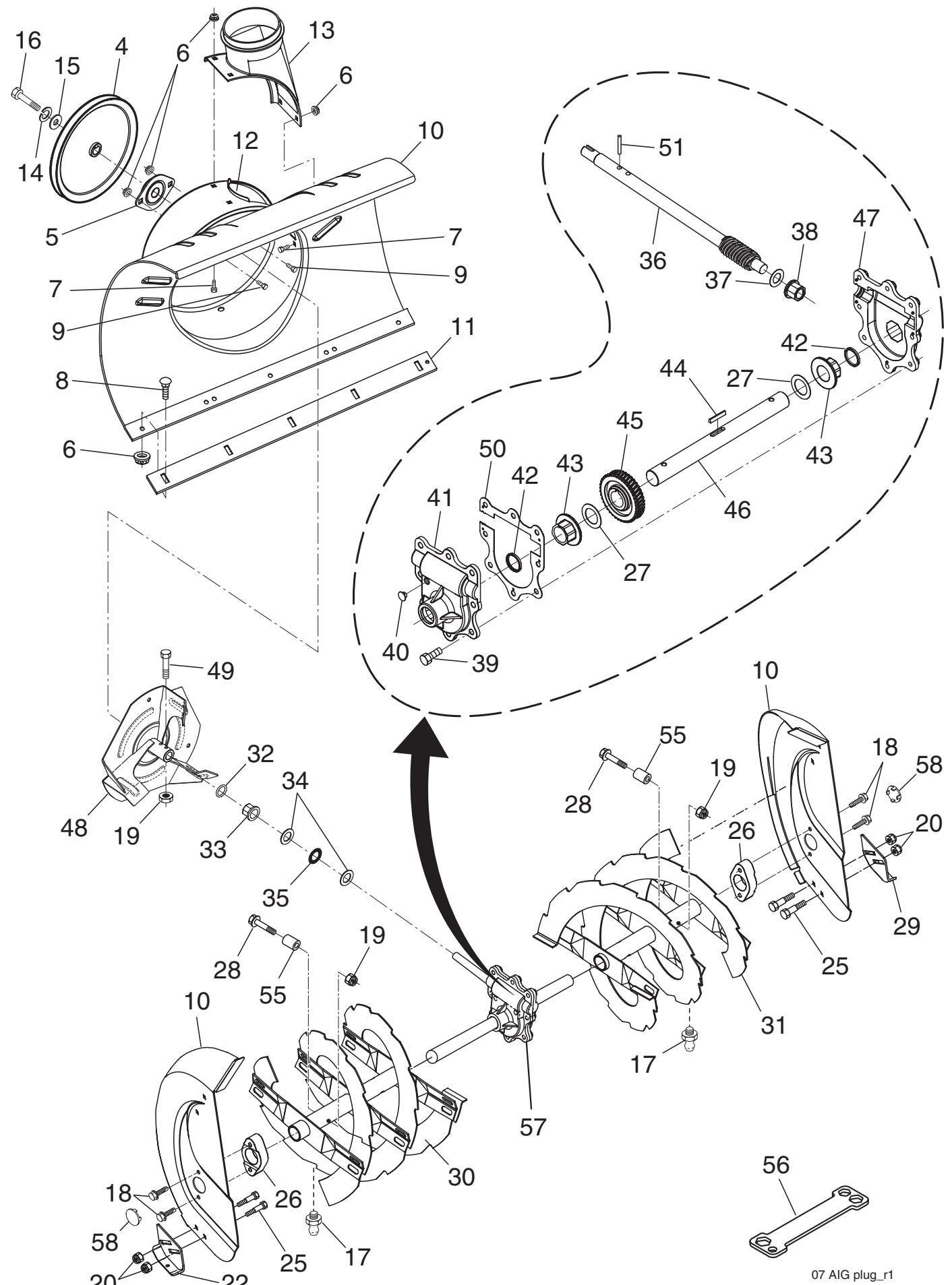
| KEY NO. | PART NO. | DESCRIPTION | KEY NO. | PART NO. | DESCRIPTION |
| 4 | 191079 | Pulley, Impeller | 30 | 413607X479 | Auger Assembly, RH |
| 5 | 188909 | Bearing Assembly, Flange | 31 | 413606X479 | Auger Assembly, LH |
| 6 | 155377 | Nut, Hex Flange 5/16-18 | 32 | 407768 | O-Ring |
| 7 | 180355 | Bolt, Flat Head, Carriage | 33 | 407769 | Bushing, Flange 3/4 |
| 5/16-18 x 5/8 | 34 | 174681 | Washer, Thrust 3/4 | ||
| 8 | 72270505 | Bolt, Carriage 5/16-18 | 35 | 174684 | Bearing, Thrust 3/4 |
| 9 | 163183 | Bolt, Hex Head | 36 | 407757 | Shaft, Impeller |
| 10 | 404929X428 | Housing, Auger | 37 | 174683 | Washer, Thrust 5/8 |
| 11 | 404932X428 | Bar, Scaper | 38 | 407758 | Bushing, Flange 5/8 |
| 12 | 178675X008 | Bracket, Corner Discharge | 39 | 407767 | Screw, Hex Head 5/16-18 x 3/4 |
| 13 | 175322 | Base, Discharge Chute | 40 | 407760 | Plug, Case |
| 14 | 10040500 | Washer, Lock 5/16 | 41 | 407761 | Housing, Gearbox, RH |
| 15 | 19111507 | Washer, Flat | 42 | 407770 | Seal, Oil |
| 16 | 74940516 | Screw, Hex Head 5/16-18 x 3/4 | 43 | 407762 | Bushing, Flange, 1" |
| 17 | 405637 | Grease Fitting | 44 | 189282 | Key, Square 1/4 x 1/4 x 7/8 |
| 18 | 179582 | Screw, Hex Head 5/16 x 1 | 45 | 407763 | Gear, Worm |
| 19 | 73800400 | Nut, Hex Lock 1/4-20 | 46 | 407764 | Shaft, Auger |
| 20 | 155377 | Nut, Hex Lock 5/16-18 | 47 | 407765 | Housing, Gearbox, LH |
| 22 | 178777X479 | Skid Plate, RH | 48 | 175321X479 | Impeller Assembly |
| 25 | 72270506 | Bolt, Carriage 5/16-18 x 3/4 | 49 | 74780426 | Screw, Hex Head 1/4-20 x 1-5/8 |
| 26 | 174658 | Bearing, Auger | 50 | 407766 | Gasket, Gearbox |
| 27 | 174697 | Washer, Thrust, 1" | 51 | 7836M | Pin, Roll 3/16 x 1-1/8 |
| 28 | 198636 | Bolt, Shear | 55 | 198638 | Spacer |
| 29 | 174762X479 | Skid Plate, LH | 56 | 180684 | Multi-Wrench |
| 57 | 196710 | Gearbox Assembly | |||
| 58 | 411939 | Plug, Bearing, Hole, HSG |
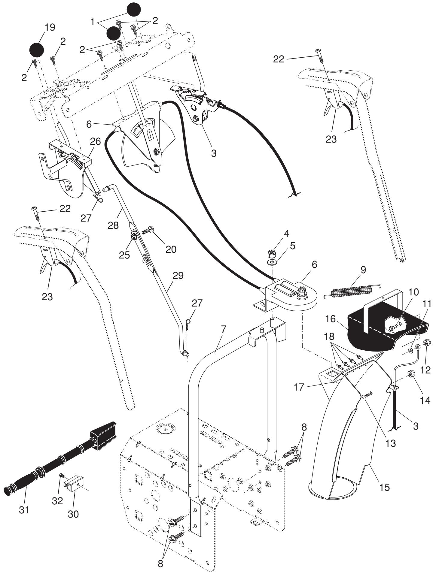
KEY PART
NO. NO.
DESCRIPTION
1 414280
Knob, Lever
2 17501010
Screw #10-24 x 5/8
3 198475
Control Assembly, Deflector
4 73800600
Nut, Lock 3/8-16
5 19131316
Washer, Flat 3/8
6 404974
Control Assembly, Chute Rotater
7 405784X479
Support, Pivot
8 150078
Screw, Hex Head 5/16-18 x 3/4
9 184505
Spring, Deflector
10 179829
Bolt, Shoulder
11 179246
Washer, Friction, Nylon
12 191730
Nut, Lock 1/4-20
13 72250505
Bolt, Carriage 5/16-18
14 751153
Nut, Lock 5/16-18
15 404770X428
Chute Assembly
16 178633X428
Deflector Assembly
17 179145
Seal, Deflector
18 128415
Rivet, Blind
19 414281
Knob, Speed Control Lever
20 72270506
Bolt, Carriage 5/16-18 x 3/4
22 74041024
Screw #10-24 x 1-1/2
23 188303
Control Assembly, Power Steering
25 155377
Nut, Lock 5/16-18
26 198474
Lever Assembly, Speed Control
27 169675
Retainer, Hairpin
28 180445
Rod, Upper, Speed Control
29 187716
Rod, Lower, Speed Control
30 405400
Clamp, Clean-Out Tool
31 192199
Tool, Clean-Out
32 194189
Screw Hi-Lo 13-16 x 5/8
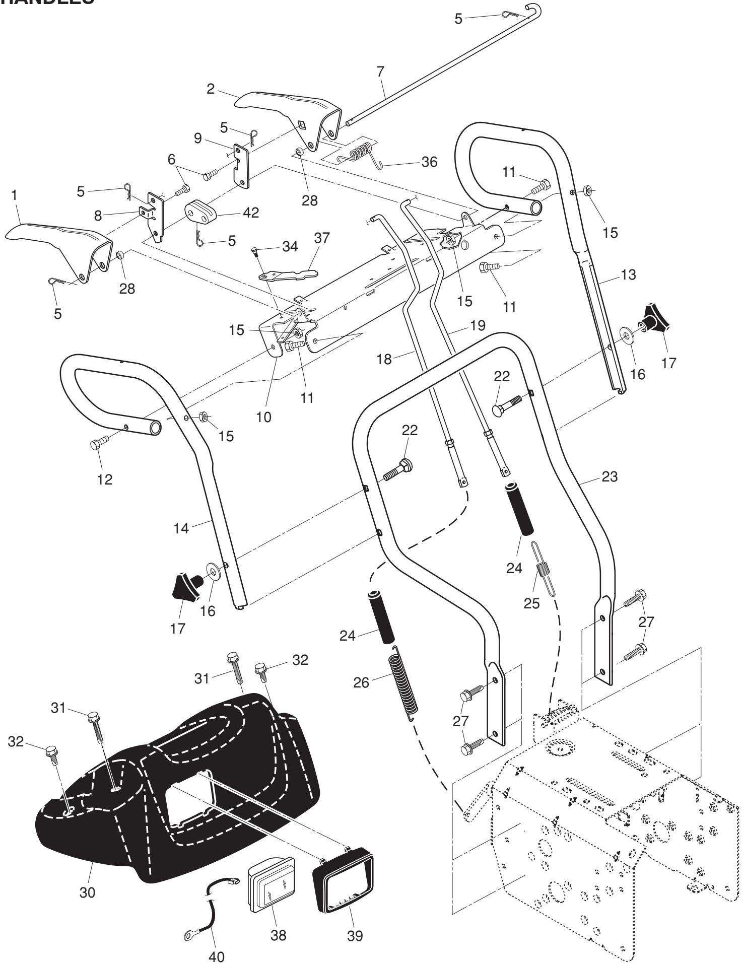
KEY PART
NO. NO.
DESCRIPTION
1 412682X479 Lever, Auger Control, RH
2 412681X479 Lever, Traction Drive Control
5 169675 Retainer, Hairpin
6 17060408 Screw, Hex Head 1/4-20 x 3/4
7 412677 Bail, Interlock
8 196333X008 Arm, Impeller Rod
9 412679X008 Arm, Traction Rod
10 412683X479 Panel, Control
11 74780524 Screw, Hex Head 5/16-18 x 1-1/2
12 74780528 Screw, Hex Head 5/16-18 x 1-3/4
13 414519X479 Handle Tube, LH
14 414518X479 Handle Tube, RH
15 751153 Nut, Lock 5/16-18
16 19131316 Washer, Flat 3/8
17 178899 Knob, Handle
18 180480 Rod,Auger Control
19 405740 Rod, Traction Control
22 72120618 Bolt,Carriage 3 / 8 - 16× 2 - 1 / 4
23 401940X479 Handle Tube, Lower
24 180447 Sleeve, Spring
25 180926 Spring, Traction Drive
26 178669 Spring,Auger Control
27 17000616 Screw, Hex Head 3/8-16 x 1
28 412680 Bushing, Pivot Lever
30 183346 Console,Panel
31 175262 Screw, Hex Head, Tapping #10-24 x 1-1/4
32 184471 Screw, Hex Head, Tapping #10-24 x 1/2
34 17060410 Screw
36 178831 Spring, Torsion, Lever
37 412675X004 Spring, Interlock
38 180927 Headlight, Flood
-- 183784 Bulb, Flood
39 178668 Bezel, Headlight
40 178770 Harness, Headlight (Flood)
42 414572 Cam, Interlock
DRIVE

KEY PART
NO. NO.
DESCRIPTION
1 401619 Chain, Drive
2 751153 Nut, Lock 5/16-18
3 402882 Clip, Retainer
4 17490508 Bolt, Hex Head 5/16-18 x 1/2
5 408981 Bearing, Flange
6 12000007 E-Ring, Retainer
9 402855 Sprocket & Shaft Assembly
11 402568 Rod, Clutch
12 402187 Shaft, Hex
13 402310 Pivot Rod, Shifter
14 401732 Yoke, Shifter
15 175344 Trunnion Bearing Assembly
17 178613 Hub, Rubber Wheel
18 198176X479 Plate, Rubber Wheel
19 74760514 Screw, Hex Head 5/16-18 x 7/8
20 179831 Ring, Rubber Wheel
21 73930500 Nut, Lock 5/16-18
22 169675 Retainer, Hairpin
23 180135 Spring, Bias
24 402691 Sprocket, Axle Shaft
25 402652 Pivot Rod, Swing Plate
26 401820 Plate, Drive
27 404307 Axle Shaft
Shaft, Friction Pulley
29 401984X479 Bracket, Shifter, Speed
31 17541008 Screw, Cap Head
32 189282 Key, Square
33 198791 Bearing, Ball
34 402394 Plate, Swing
35 402511 Spacer, Bearing
36 402393 Pulley, Friction
37 132010 Nut, Lock 5/16-18
41 12000012 Ring, Retaining
43 402878 Spring, Return
44 9465M Pin, Roll
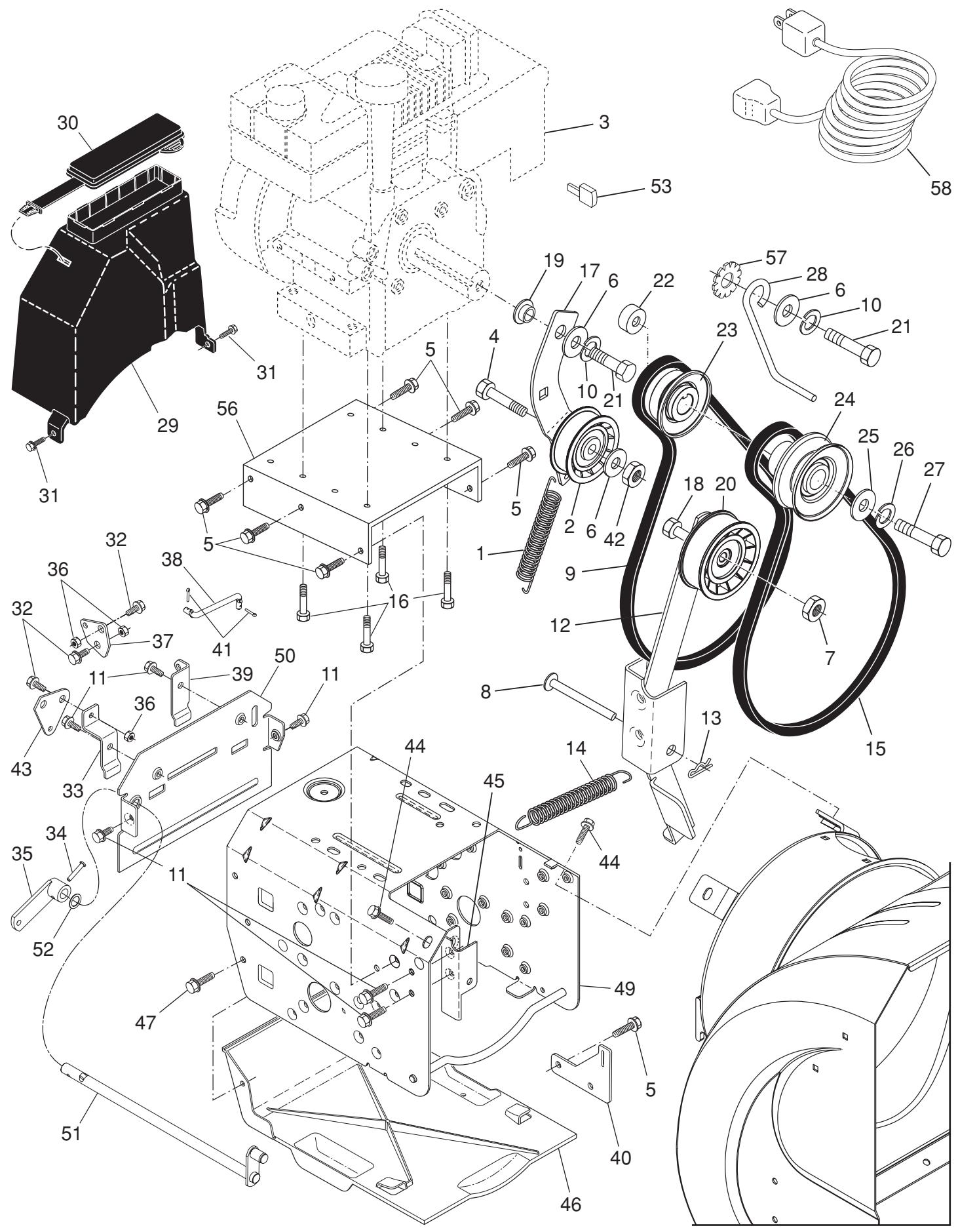
| KEY NO. | PART NO. | DESCRIPTION | KEY NO. | PART NO. | DESCRIPTION |
| 1 | 414557 | Spring, Traction Idler | 27 | 851084 | Screw, Hex Head 3/8-24 x 1-3/8 |
| 2 | 180522 | Pulley, Idler (2-1/4) | 28 | 155452 | Guide, Belt |
| 3 | ---- | Engine, Tecumseh, Model Number LH318SA (For engine service and replacement parts, call Tecumseh Products at 1-800-558-5402) | 29 | 192213 | Belt Cover Assembly (Includes Toolbox Cover) |
| 30 | 178830 | Cover, Toolbox | |||
| 31 | 17490408 | Screw, Hex Head 1/4-20 x 1/2 | |||
| 4 | 74780520 | Screw, Hex Head 5/16-18 x 1-1/4 | 32 | 402881 | Bolt, Shoulder 5/16-18 |
| 5 | 150078 | Screw | 33 | 403096X004 | Bellcrank Shifter |
| 6 | 59289 | Washer, Flat | 34 | 198580 | Clevis Pin |
| 7 | 166785 | Nut, Jam, Lock 5/16-18 | 35 | 405485 | Arm, Auger Control |
| 8 | 175330 | Pin, Idler Pivot | 36 | 191730 | Locknut, Hex |
| 9 | 407908 | V-Belt, Traction Drive | 37 | 402856X004 | Plate, Clutch |
| 10 | 10040500 | Washer, Lock 5/16 | 38 | 187101 | Link, Speed Control |
| 11 | 17490508 | Screw, Hex Washer Head 5/16-18 x 1/2 | 39 | 416717X004 | Bracket, Clutch |
| 40 | 413429X479 | Bracket, Traction | |||
| 12 | 410420 | Impeller Arm Assembly | 41 | 700279 | Hairpin, Cotter 3/32 x 1/2 |
| 13 | 85179 | Retainer, Hairpin | 42 | 73930500 | Locknut, Hex |
| 14 | 178828 | Spring, Brake | 43 | 403097X004 | Plate, Shifter |
| 15 | 408007 | V-Belt, Impeller Drive | 44 | 17000616 | Screw, Hex Head |
| 16 | 150406 | Screw, Hex Head 3/8-16 x 1-1/4 | 45 | 175324X479 | Pivot Bracket, Impeller Idler Arm |
| 17 | 187786 | Arm, Idler | 46 | 410877 | Pan, Frame Bottom |
| 18 | 74780524 | Screw, Hex Head 5/16-18 x 1-1/2 | 47 | 184471 | Screw |
| 19 | 175331 | Bushing, Idler Pivot | 49 | 409346X428 | Frame Assembly |
| 20 | 180523 | Pulley, Idler (2-3/4) | 50 | 402685X428 | Plate, Frame End |
| 21 | 74610516 | Screw, Hex Head 5/16-24 x 1 | 51 | 406109 | Shaft, Auger Control |
| 22 | 409475 | Spacer, Engine Pulley | 52 | 57079 | Washer, Hardened |
| 23 | 180478 | Pulley, Engine, Traction Drive | 53 | 35062 | Key, Safety |
| 24 | 179157 | Pulley, Engine, Impeller Drive | 56 | 183528X428 | Plate, Engine |
| 25 | 400026 | Washer, Flat 3/8 | 57 | 11050500 | Washer, Lock, External Tooth |
| 26 | 850263 | Washer, Lock 3/8 | 58 | 198563 | Power Cord |
REPAIR PARTS WHEELS
SNOW THROWER - MODEL 961980018 (96198001801)
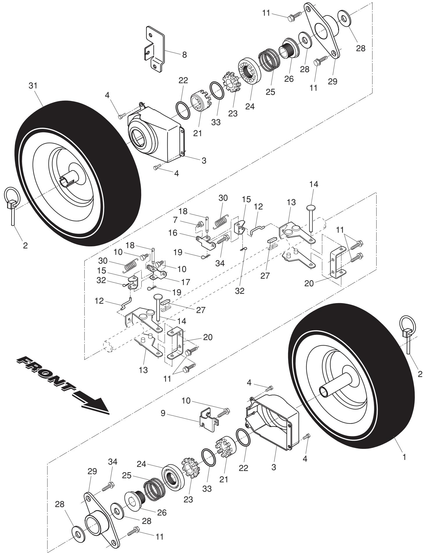
| KEY NO. | PART NO. | DESCRIPTION |
| 1 | 192092X421 | Wheel Assembly, 16", with Power Steering, LH |
| 2 | 155443 | Pin, Klik 1/4 |
| 3 | 405161 | Cover, Power Steering |
| 4 | 184471 | Screw, Shoulder, Hex Head #10-24 x 1/2 |
| 7 | 17060410 | Screw, Hex Head 1/4-20 x 5/8 |
| 8 | 410294 | Bracket, Steering Cable, RH |
| 9 | 410293 | Bracket, Steering Cable, LH |
| 10 | 17600406 | Screw, Hex Head 1/4-20 x 1/2 |
| 11 | 17490508 | Screw, Hex Head 5/16-18 x 1/2 |
| 12 | 405077 | Link, Steering Lever |
| 13 | 193506X479 | Lever Assembly, Steering |
| 14 | 182015 | Pin, Steering Lever |
| 15 | 194944X008 | Bellcrank |
| 16 | 194939X008 | Bracket Assembly, LH Steering |
| 17 | 194943X008 | Bracket Assembly, RH Steering |
| 18 | 181847 | Pin, Steering Bellcrank |
| 19 | 85179 | Retainer, Hairpin |
| 20 | 179148X479 | Bracket, Lever Assembly |
| 21 | 192126 | Driver, Wheel |
| 22 | 182466 | Ring, Wire Retainer |
| 23 | 187622 | Lobe, Wheel |
| 24 | 194941 | Slide, Clutch |
| 25 | 179139 | Spring, Clutch Slide |
| 26 | 194940 | Lobe, Axle |
| 27 | 189282 | Key, Square 1/4 x 1/4 x 7/8 |
| 28 | 174697 | Washer, Thrust (1") |
| 29 | 179830 | Bearing, Axle |
| 30 | 193885 | Spring, Return, Steering Latch |
| 31 | 192093X421 | Wheel Assembly, 16", with Power Steering, RH |
| 32 | 700279 | Clip, Retainer |
| 33 | 12000045 | Ring, Retaining |
| 34 | 146315 | Screw, Tapping, Hex Head 5/16-18 x 3/4 |
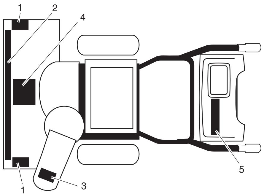
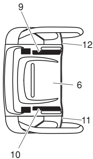
KEY PART NO. NO.
DESCRIPTION
1 181037
Decal, Danger
2 187869
Decal, Poulan
3 181035
Decal, Danger, Deflector
4 181042
Decal, Danger
5 187894
Decal
6 181033
Decal, Instruction
9 415475
Decal, Speed Control
10 183730
Decal, Remote Deflector Control
11 415399
Decal, LH Trigger
12 415398
Decal, RH Trigger
415332
Owner's Manual, English
415333
Owner's Manual, French
SERVICE NOTES
LIMITED WARRANTY
The Manufacturer warrants to the original consumer purchaser that this product as manufactured is free from defects in materials and workmanship. For a period of two (2) years from date of purchase by the original consumer purchaser, we will repair or replace, at our option, without charge for parts or labor incurred in replacing parts, any part which we find to be defective due to materials or workmanship. This Warranty is subject to the following limitations and exclusions.
- This warranty does not apply to the engine or components parts thereof. Please refer to the applicable manufacturer's warranty on these items.
- Transportation charges for the movement of any power equipment unit or attachment are the responsibility of the purchaser. Transportation charges for any parts submitted for replacement under this warranty must be paid by the purchaser unless such return is requested by the manufacturer.
- The Warranty period for any products used for rental or commercial purposes is limited to 90 days from the date of original purchase.
- This Warranty applies only to products which have been properly assembled, adjusted, operated, and maintained in accordance with the instructions furnished. This Warranty does not apply to any product which has been subjected to alteration, misuse, abuse, improper assembly or installation, delivery damage, or to normal wear of the product.
- Exclusions: Excluded from this Warranty are belts, shear pins, normal wear, normal adjustments, standard hardware and normal maintenance.
- In the event you have a claim under this Warranty, you must return the product to an authorized service dealer. Should you have any unanswered questions concerning this Warranty, please contact:
Poulan
Customer Service Department
1030 Stevens Creek Road
Augusta, GA 30907 USA
In Canada contact:
Poulan, Customer Service Department
5855 Terry Fox Way
Mississauga, Ontario
L5V 3E4
giving the complete mfg. ID#, serial number and date of purchase of your product and the name and address of the authorized dealer from whom it was purchased.
THIS WARRANTY DOES NOT APPLY TO INCIDENTAL OR CONSEQUENTIAL DAMAGES AND ANY IMPLIED WARRANTY ARE LIMITED TO THE SAME TIME PERIODS STATED HEREIN FOR OUR EXPRESSED WARRANTY. Some areas do not allow the limitation of consequential damages or limitations of how long an implied Warranty may last, so the above limitations or exclusions may not apply to you. This Warranty gives you specific legal rights, and you may have other rights which vary from locale to locale.
This is a limited Warranty within the meaning of that term as defined in the Magnuson-Moss Act of 1975.
Poulan


- POULAN PRO
- OWNER'S MANUAL
- MODEL NUMBER
- 961980018
- SNOW THROWER
- A WARNING
- IMPORTANT
- SAFE OPERATION PRACTICES FOR WALK-BEHIND SNOW THROWERS
- TRAINING
- PREPARATION
- OPERATION
- CLEARING A CLOGGED DISCHARGE CHUTE
- MAINTENANCE AND STORAGE
- CUSTOMER RESPONSIBILITIES
- TABLE OF CONTENTS
- PARTS PACKED SEPARATELY IN CARTON
- ASSEMBLY / PRE-OPERATION
- UNFOLD UPPER HANDLE
- INSTALL SPEED CONTROL ROD (SEE FIGS. 1 AND 2)
- INSTALL TRACTION DRIVE CONTROL ROD (SEE FIGS. 3 AND 4)
- INSTALL AUGER CONTROL ROD (SEE FIGS. 5 AND 6)
- INSTALL DISCHARGE CHUTE / CHUTE ROTATOR HEAD (SEE FIG. 7)
- CHECK TIRE PRESSURE
- KNOW YOUR SNOW THROWER
- DANGER
- MEETS A.N.S.I. SAFETY REQUIREMENTS
- HOW TO USE YOUR SNOW THROWER
- STOPPING
- TRACTION DRIVE
- AUGER
- ENGINE
- TO USE FUEL SHUT-OFF VALVE (SEE FIG. 9)
- TO USE THROTTLE CONTROL (SEE FIG. 10)
- TO USE CHOKE CONTROL (SEE FIG. 11)
- TO CONTROL SNOW DISCHARGE (SEE FIGS. 12 & 13)
- TO THROW SNOW (SEE FIG. 14)
- USING THE CLEAN-OUT TOOL (SEE FIG. 15)
- TO MOVE FORWARD AND BACKWARD (SEE FIG. 16)
- TO ADJUST SKID PLATES (SEE FIG. 17)
- SCRAPER BAR
- BEFORE STARTING THE ENGINE
- CHECK ENGINE OIL LEVEL (SEE FIG. 18)
- ADD GASOLINE (SEE FIG. 18)
- TO START ENGINE
- COLD START - ELECTRIC STARTER
- WARM START - ELECTRIC STARTER
- COLD START - RECOIL STARTER
- WARM START - RECOIL STARTER
- BEFORE STOPPING
- IF RECOIL STARTER HAS FROZEN
- SNOW THROWING TIPS
- MAINTENANCE
- GENERAL RECOMMENDATIONS
- BEFORE EACH USE
- LUBRICATION
- TIRES
- LUBRICATION CHART
- V-BELTS
- AUGER GEAR CASE
- TRACTION DRIVE SYSTEM
- TO CHANGE ENGINE OIL
- MUFFLER
- SPARK PLUG
- CLEANING
- SERVICE AND ADJUSTMENTS
- TO ADJUST SNOW THROWER HEIGHT
- CHUTE DEFLECTOR
- SHEAR BOLTS (SEE FIG. 19)
- AUGER SHEAR BOLTS
- IMPELLER SHEAR BOLTS
- TO REMOVE BELT COVER (SEE FIG. 20)
- TO REPLACE BELTS (SEE FIG. 21)
- TO REMOVE WHEELS (SEE FIG. 22)
- CARBURETOR
- ENGINE SPEED
- STORAGE
- FUEL SYSTEM
- ENGINE OIL
- CYLINDER
- OTHER
- TROUBLESHOOTING
- AUGER HOUSING / IMPELLER ASSEMBLY
- DRIVE
- REPAIR PARTS WHEELS
- SNOW THROWER - MODEL 961980018 (96198001801)
- SERVICE NOTES
- LIMITED WARRANTY
- POULAN
Marque : POULAN
Modèle : PRO 961980018
Catégorie : Déneigeuse