503CW - Appareil photo moyen format HASSELBLAD - Notice d'utilisation et mode d'emploi gratuit
Retrouvez gratuitement la notice de l'appareil 503CW HASSELBLAD au format PDF.

| Type de produit | Appareil photo reflex mono-objectif moyen format 6×6 cm |
| Marque | Hasselblad |
| Modèle | 503CW |
| Dimensions (boîtier nu) | Environ 180 mm × 114 mm × 110 mm (avec objectif Planar CFE 2.8/80 mm et magasin A12) |
| Poids (boîtier nu) | 0,6 kg |
| Poids (avec objectif et magasin) | 1,5 kg |
| Alimentation | Mécanique, sans pile ; moteur Winder CW (optionnel) nécessite piles |
| Avancement du film | Manuel ou motorisé avec Winder CW |
| Commande du flash | TTL/OTF (503CW uniquement) ; compatibilité SCA390 ; plage ISO 64–4000 |
| Objectifs compatibles | Série C (CF, CFi, CFE, CB) avec obturateur central |
| Viseur | Capuchon repliable interchangeable ; viseurs prismatiques disponibles |
| Écran de visée | Acute-Matte D (interchangeable) |
| Monture du trépied | Filetage 1/4″ et 3/8″ ; plaque pour attache rapide |
| Vitesses d'obturation | 1 s à 1/500 s, pose B |
| Synchronisation flash | Sur toutes les vitesses (1/500 s max) |
| Magasins compatibles | Magasins Hasselblad A12, A24, E12, E24, Polaroid, etc. |
| Entretien et nettoyage | Nettoyer les poussières avec une soufflette ou un pinceau doux ; éviter températures extrêmes, humidité et chocs |
| Pièces détachées et réparabilité | Pièces disponibles auprès des centres de service agréés Hasselblad |
| Garantie | Garantie internationale d'un an |
FOIRE AUX QUESTIONS - 503CW HASSELBLAD
Questions des utilisateurs sur 503CW HASSELBLAD
0 question sur cet appareil. Repondez a celles que vous connaissez ou posez la votre.
Poser une nouvelle question sur cet appareil
Téléchargez la notice de votre Appareil photo moyen format au format PDF gratuitement ! Retrouvez votre notice 503CW - HASSELBLAD et reprennez votre appareil électronique en main. Sur cette page sont publiés tous les documents nécessaires à l'utilisation de votre appareil 503CW de la marque HASSELBLAD.
MODE D'EMPLOI 503CW HASSELBLAD
H A S S E L B L A D

User manual
ENG
Hasselblad 501CM and 503CW - cornerstones of the 6 × 6 system
Thank you for choosing Hasselblad equipment and welcome to the best and most comprehensive medium-format photographic system in the world. Hasselblad cameras provide a sound investment for your future in photography and you can rely on the standards and service that have become the benchmark in the medium-format. Hasselblad is the choice of the world's leading photographers, and the name is synonymous with compatibility, reliability and image quality, reaching beyond the ends of the earth and into space.

The 501CM and 503CW cameras are simple to use, battery independent, and fully compatible with the Hasselblad system. They feature the sophisticated GMS (Gliding Mirror System) which provides a full viewfinder image with virtually all Hasselblad 'C' lenses. Although fundamentally 6 × 6 cm cameras, they also accepts masks for the 6 × 4.5 cm or panoramic 6 × 3 cm formats without having to change film magazines. The bright viewfinder image is further enhanced by the new improved focusing screen from the brilliant 'Acute-Matte D' range. Altogether, a winning combination for professional or dedicated amateur use.
You have access to the whole range of Hasselblad 'C' series lenses both old and new. Lenses are specially manufactured for Hasselblad by Carl Zeiss of Germany – the indisputable leader in camera optics. The accessory range – the most comprehensive medium-format assortment in the world – allows you to extend your
photographic potential even further providing an almost limitless flexibility for superb images whatever your field. The Hasselblad System features interchangeability of 14 different lenses, 1.4X and 2X teleconverters, magazines for different image formats and films including Polaroid type films, viewfinders with or without exposure metering capabilities, a number of focusing screens and a variety of accessories to suit your special requirements.
With the Winder CW, specifically designed for the 503CW, fast sequential photography and various choices of remote control, including IR, are at your disposal. The dedicated D-Flash is another powerful option for exploiting the 503CW's additional TTL/OTF facilities.
This instruction manual describes in detail how to operate your camera, so please read it carefully. If you have a query do not hesitate to contact your dealer -we want you to be 100% satisfied! You may also contact us directly over useability, construction, design, etc as we welcome your feedback in order to improve our products. Your dealer can also provide you with the latest in news and technical developments from Hasselblad. A quarterly magazine -FORUM -is published with the emphasis on photographic imagery featuring photographers from all over the world to provide you with inspiration! Our internet site - www.hasselblad.com - is a source of general and technical information and you can e-mail us - info@hasselblad.se - for further inquiries.
Contents
Introduction
Contents
- Parts & components
- GETTING STARTED
- Front protective cover
- Rear cover MultiControl
- Attaching the lens
- Removing the magazine
- Attaching and removing the magazine
- Magazine status indicator
- Opening the focusing hood
- Built-in magnifier
- Focusing screen and viewfinder image
- Closing the focusing hood
- Strap attachment and removal
- Left hand grip
- Exposure release
- MAGAZINE OPERATION
- Parts and components
- Loading the magazine
- Step-by-step film loading
- Magazine tips
- Magazine load status
- Removing film from the magazine
- Film tab holder
- Installing format masks
- Film plane position
- LENSES
- Parts and components
12.Shutter speed and aperture - Exposure
-
Warning mark
-
Exposure values
- Interlocked shutter speed/aperture
- Focusing and depth of field
- Depth of field preview
- Pre-release and cable release
- Double exposure
- Flash synchronization
- Infrared photography
THE VIEWFINDER SYSTEM
- Changing the focusing hood or viewfinder
- Changing the magnifier
- Changing the focusing screen
- Winding crank (503CW only)
-
ACCESSORIES
-
Accessory rail
- Flash
- Winder CW (503CW only)
- Snap-lock flash grip
- Rear cover MultiControl
- Tripod quick coupling S
- Viewfinders
- Professional lens shade
- Close-up accessories
- Further reading
- Acute-Matte D adjustment table
- Troubleshooting
- Technical specifications
- Equipment care, service and guarantee

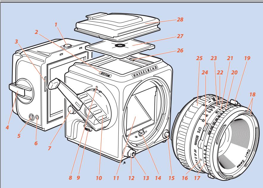
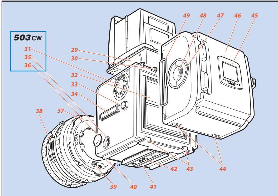
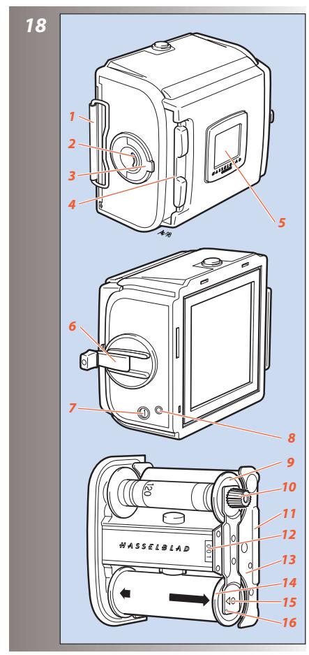
Parts & Components
- Magazine catch
- Nameplate
- Magazine driving gear
- Film winding crank
- Frame counter
- Magazine status indicator
- Strap lug
- Winding crank index (503CW only)
- Pre-release button
- Winding crank
- Viewfinder mirror
12.Shutter release button - Threaded cable release socket
- Drive shaft
- Lens release button
- Exposure value index
- Exposure value scale
- External and internal lens accessory mount
- PC flash terminal
20.Shutter speed ring - Aperture ring and scale
- Depth-of-field scale
- Central lens index
24.Shutter speed and aperture interlock button - Focusing ring and scale
- Screen retaining clip
-
Focusing screen: Acute-Matte D screen
-
Focusing hood
- Focusing hood magnifier
- Magazine hook
- Film speed selector (503CW only)
- Auxiliary shutter
- Strap lug
- Accessory rail
- Dedicated flash connector (503CW only)
- Connector cover (503CW only)
- Lens locating index
- Depth-of-field preview knob
- Lens drive shaft
- Camera supports
- Quick-coupling plate
- Tripod threads, 1/4'' & 3/8''
- Magazine supports
- Magazine support slots
- Film tab holder
- Magazine slide holder
- Film holder key
- Film load indicator
- Magazine slide
*Acute-Matte D designed by MINOLTA
In the text, positions of components and orientation are described in relation to the camera as seen when taking a photograph, that is, with the lens at the front, the viewfinder on the top and the winding crank on the right hand side.
The relevant illustrations to a particular section are indicated by the figures beside the small headings in the text.
For the sake of simplicity, most illustrations corresponding to both the 501CM and the 503CW models, show a 'neutral' 500 camera. The correct component appears when specifically described, for example, in the section on TTL/OTF flash. Some sections of the text are also specific only to the 503CW, but they are marked as such.
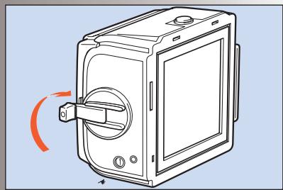
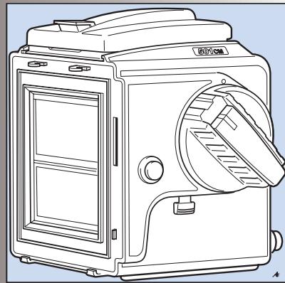
Getting Started
This section describes how to prepare your camera for use as well as the basic operations. Follow the instructions step-by-step to avoid damaging the equipment.
Check that the winding crank on the right hand side of the camera is locked thus ensuring that the camera is fully wound. If the crank is not locked, rotate it clockwise until it does lock, thereby winding the camera.
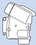
Front protective cover
Turn the cover (bayonet fitting) in the direction of the arrow and lift it out. For protection, do not remove it until you are ready to attach a lens.

The front protective cover can only be removed when the camera is fully wound.
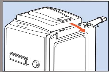
Rear cover MultiControl
Depress the catch, tilt the cover backwards, and lift it off. Do not remove it though until you are ready to attach a magazine.
Always replace the cover to protect the auxiliary shutter when storing the camera body without a magazine attached.
See later sections on the other uses of the Rear cover MultiControl
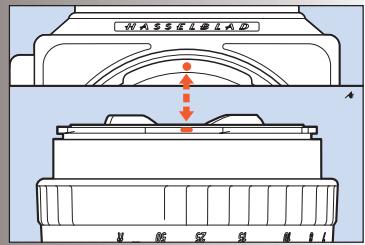
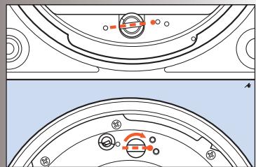
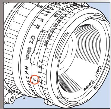
Attaching the lens
5,6
Make sure that both camera and lens are fully wound. The illustration shows the correct relationship between the drive shaft, the lens drive coupling and their indexes.
If the lens is not wound, you can insert a small coin or similar in the coupling slot and rotate it clockwise until it locks (about 4/5 of a turn)
When you have aligned the red index on the lens with the one on the camera as in the illustration, the lens will drop easily into the bayonet fitting. You can then rotate it clockwise until it stops with a faint click as the lens catch locks it in place.
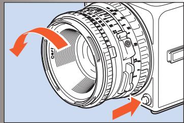
Removing the lens
7
Depress the lens release button and rotate the lens counter-clockwise until it stops and lift it out of the mount.

You can only remove the lens when the camera is fully wound and not in the pre-released mode (see "pre-release and cable release).
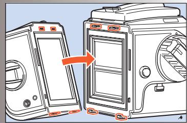
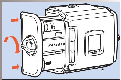
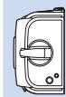
Attaching and removing the magazine
8,9,10
Ensure that the magazine slide is fully inserted with the hinge towards the front of the camera (see fig 8) and that the magazine status indicator is white. If the indicator is red then see under "Magazine status indicator". It is also advisable to have the camera fully wound.
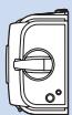
Rest the magazine on the magazine supports making sure that the lugs are properly engaged in the recesses. Carefully swing the magazine towards the camera body and check that the camera's upper support hooks fit into the slots in the magazine.
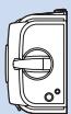
Push the magazine gently but firmly against the hooks while sliding the magazine catch to the right. Release the button when the magazine has made contact with the camera body, and then push the button to the left to ensure that it has reached the locked position. Remove the slide to positively lock the magazine to the camera body.
Removing the magazine
Removing the magazine is simply the reverse of the attaching procedure.
It is advisable to have the camera fully wound and the magazine indicator displaying white. See 'Magazine Operation' for a general explanation of these magazine features.
Insert the magazine slide fully with the hinge towards the front of the camera. Slide the magazine catch to the right, swing the magazine back and lift it off the lower supports.
The magazine cannot be removed without first inserting the magazine slide.
! Note also that the camera cannot be operated when a magazine, with slide inserted, is attached to the camera.
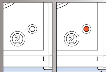
Magazine status indicator
11
The status indicator on the right hand side of the magazine shows white when the magazine is ready to operate and red when the film has not been advanced after an exposure. If the status indicator shows red, release the camera first before attaching the magazine. Then, winding the camera again will automatically advance the film by one frame. See 'Magazine Operation' for full details about magazines.

Do not attach a magazine showing white to a camera that is not rewound! Wind the camera first or you will lose a frame.

Do not attach a magazine showing red to a fully wound camera! This could result in a double exposure.
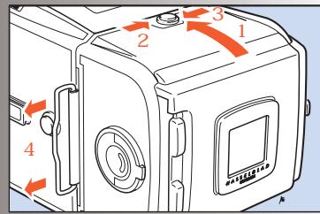
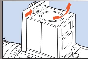
Opening the focusing hood
12
Lift the lid by firmly gripping the tab on its rear edge, and swinging it up to a vertical position. The hood unfolds automatically and locks in the open position.
Built-in magnifier
13
The magnifier flips up into the viewing position when the oval button inside the lid is moved to the right, as in the illustration.
To fold the magnifier down simply press it back down towards the lid until it locks into place. It can easily be exchanged to suit individual eyesight (see "Changing the magnifier").
Focusing screen and viewfinder image
500-series cameras are fitted with an Acute-Matte D focusing screen for unrivalled brightness and sharpness. The screen can easily be exchanged for others specially designed for various applications (see "Changing the focusing screen").
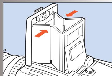
Closing the focusing hood
14
Fold away the magnifier by pressing it back down towards the lid until it locks into place. 'Pinch' in the side plates at the hinge points and then push the lid lightly backwards. The hood then automatically folds back down.
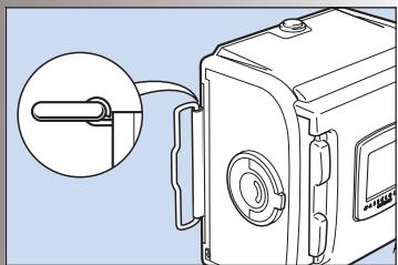
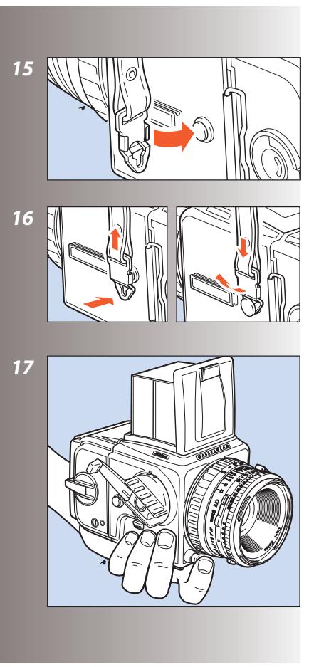
Strap attachment and removal
15, 16
Place the main body of the strap clip over one of the camera's strap lugs. Press the tip of the clip towards the camera while pulling back on the strap so that the clip slides over the lug and locks into position. To remove the strap, lift the clip locking plate high enough to be able pass over the camera lug. Slide the clip in the direction away from the strap until it is free.
Left hand grip
17
Withouta WinderCW(44105)attached(503CW only), you may find that holding the camera in your left hand is the most convenient grip; operating the exposure release button with your index finger. Your right hand is then free for focusing, setting the exposure, rewinding, and
changing the lens or magazine. The Snap-lock flash grip (45169) also acts as an ergonomic camera grip, see under 'Accessories'.
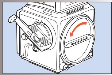
Exposure release
Before you can take a photograph, you must remove the magazine slide. The magazine will then be locked on the camera body, and the camera release button will be unlocked.
After exposure, the viewfinder remains dark until you have rewoud the camera by one full turn of the crank, which also advances the film.
Magazine operation
Hasselblad film magazines provide the opportunity to vary format, length and type of film used. They can be quickly and easily switched mid-film without the loss of a single frame.
Operation of the magazines is not difficult but pay particular attention to the section on loading. Go through the procedure one step at a time and practice a little until you feel confident. Note especially which way round the spool of film is placed and the positioning of the backing paper under the clamp bar.
The film is automatically advanced frame-by-frame in the magazine by the camera
winding mechanism and consequently only when attached to the camera body. Therefore when separated, the magazine and camera body could become unmatched. This can be determined by checking the magazine status indicator or by the winding crank status.
Try to adopt a routine that suits you regarding winding and removal as well as checking on the status of each item. This will ensure that the camera/lens/magazine combination status is always fully operative.
Parts & components
- Magazine slide
- Film load indicator
- Film holder key
- Magazine slide holder
- Film tab holder
- Film winder crank
- Frame counter
- Film advance indicator
- Film take-up spool
- Grooved take-up knob
- Film clamp
- Film holder number
- Spool clamp bar
- Film supply spool
- Film load index
- Film load index for Ilford black & white film only
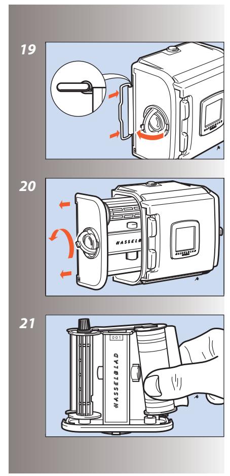
Loading the magazine
The magazine can be loaded on, or off the camera. If it is to be loaded off the camera, then the magazine slide must be inserted first.
In either case, when inserting the slide ensure that its flat side is towards the rear (see detail in illustration 19) as this facilitates the removal of the film holder.
Step-by-step film loading
19-26
Follow the procedure below in the correct order.
- Fold out the film holder key.
- Turn the key counter-clockwise and withdraw the film holder (magazine insert).
- Place an empty take-up spool under the grooved knob of the spool clamp bar. Insert a roll of film under the other end of the bar, turned the same way as in the illustration. Be sure to remove all of the paper band surrounding a new roll of film.
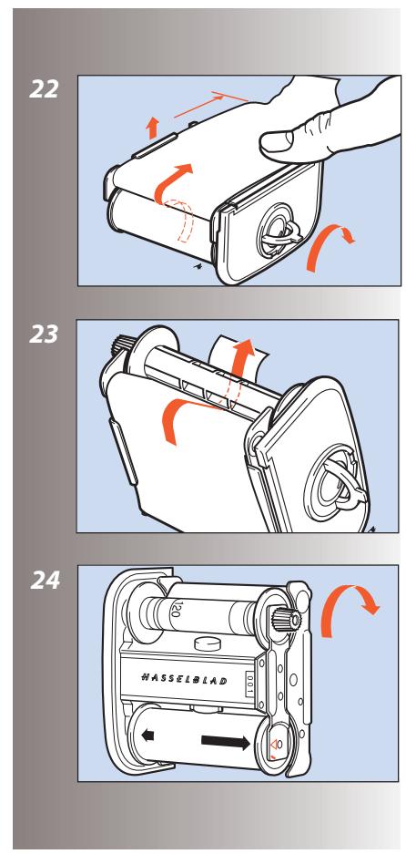
- Turn the film holder key clockwise to open the film clamp. Pull 8 - 10 cm (3 - 4 in.) of paper backing off the film roll and slide the edge under the clamp.
- Insert the tongue of the backing paper into the slot in the take-up spool.
-
Turn the grooved knob clockwise until the arrow on the paper backing is aligned opposite the triangular index (or oblong index with Ilford blackwhite film, see Magazine tips) on the spool clamp bar, but no further.
-
Turn the film holder key counter-clockwise and insert the film holder into the magazine. Ensure that it is correctly positioned. Turn the film holder key clockwise to lock the film holder in the magazine and then fold the key back into place.
- Fold out the film crank and rotate it clockwise about ten turns until it stops. Then turn it counter-clockwise and fold it in. The figure (1) will now be displayed in the automatic frame-counter window indicating that the magazine is loaded and ready for use.
Magazine tips
- The magazine's film winding crank is only blocked at frame 1. A partially exposed film may be wound off at any frame afterwards.
- On the rear of the magazine is a slide pocket where the magazine dark slide can be kept when not in use. Turn the slide with the hinge towards the rear to fold the bow fully into the slide pocket recesses.
- Do not put the film holder down on an unclean surface or where it can attract dust.
- Clean out the magazine housing regularly removing not only dust and particles but also any scraps of paper from previous rolls that may have remained inside.
Each magazine housing and film holder form a carefully matched pair. Be careful, therefore, when loading more than one magazine
at a time not to switch housings and holders. The last three figures of the housing serial number should correspond with the serial number on the film holder.
- Load and unload the magazine away from direct light sources.
- If you keep the slide inserted in an attached magazine, it will act as an exposure lock to prevent inadvertent exposures when the camera and shutter have been wound on.
- Align the arrow on the paper backing of all Ilford black & white films against the oblong index (and no further) on the spool clamp bar and not the triangular index as normal.
Magazine load status
27
In the centre of the film holder key there is a crescent-shaped indicator window that shows white when the magazine is freshly loaded. It gradually changes to red as the film is wound through. An all red indicator shows that either the film is used up or that the magazine is empty.
Removing film from the magazine
28
When the last frame has been exposed and wound on, the magazine blocks the camera for further release.
Wind off the film by folding out the film winding crank, and rotate it clockwise until you can feel the film leaving the supply spool.
You can now withdraw the film holder from the
magazine and remove the exposed film.
The frame counter is automatically reset when the film holder is withdrawn from the magazine.
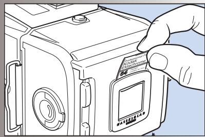
Film tab holder
29
The end tab of the film pack can be inserted in the holder on the back of the magazine as a reminder of the kind of film that has been loaded into the magazine.
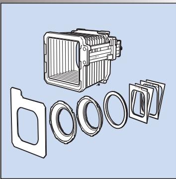
Installing format masks
30
The body's rear plate has an accurately machined mount that accepts the 6x4.5 and 6x3 panoramic format masks.
To install a mask, push it in place in the mount. The masks can be used horizontally or vertically.
Each format mask has a corresponding viewfinder mask which is placed over the focusing screen.

Do not forget to install the corresponding viewfinder mask and align according to format mask orientation.
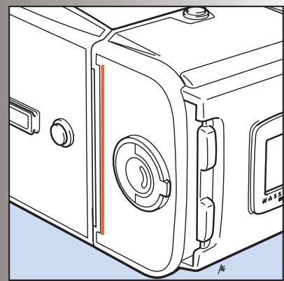
Film plane position
31
In close-up photography the film-to-subject distance can be an important factor when determining an accurate focus setting. The red line in the illustration marks the location on the film magazines that coincides with the film plane position.
Lenses
500 series cameras are compatible with lenses that have an integral leaf shutter, namely, all C series lenses. F series lenses are compatible only with cameras from the 200 series.
CFi / CFE lenses are the latest developments and are mentioned and illustrated here as the conventional choice.
C, CF and CB lenses, although differing in specification and appearance to CFi / CFE lenses, are operated in a very similar manner but please see the relevant instruction manuals for complete details.
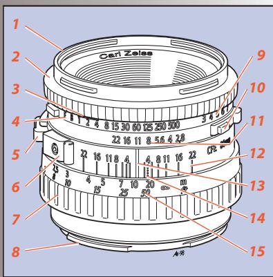
Parts & components
32
The illustration shows the Planar CFE 2.8/80 mm lens but the layout of the parts is identical on all CFi /CFE lenses.
- External and internal bayonet mount
2.Shutter speed ring - Warning mark
4.Shutter speed scale - Depth-of-field preview knob
- PC flash terminal with safe lock
- Focusing ring
- Lens bayonet plate with red index
-
Exposure value (EV) scale
10.Shutter speed/aperture interlock button -
Aperture ring and scale
- Depth-of-field scale
- Central index
- Infrared focusing index
- Focusing distance scale
Shutter speed and aperture
The shutter speed selector ring is the ring located closest to the front of the lens. To set the speed, turn the ring until the desired marked shutter speed position aligns with the central lens index.
The white scale shows the shutter speeds, and the orange scale the exposure values (EV).
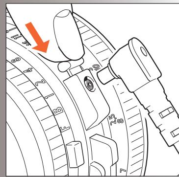
The orange F' setting is used only when the lens is attached to a Hasselblad camera in the 200 or 2000 series with a focal plane shutter. The operation of the diaphragm is not affected. The F' setting can only be engaged/disengaged when the orange lever is pressed.
If the F setting is used, exposure errors will occur since the shutter remains open.
The aperture setting ring is the second closest ring to the front of the lens. The aperture value is also set against the central lens index. The diaphragm is automatic and stops down to the preset working aperture at the start of the exposure sequence.
Exposure
33
As a general rule for all shutter speed settings except B, you should keep the release button depressed until the lens shutter has opened and
closed fully. This is especially important at shutter speeds from 1s to 1/4s , as the auxiliary shutter remains open only when the button is kept depressed (see also 'Warning Mark' below).
If you remove the magazine, you can see the auxiliary shutter, consisting of two blinds, covering the rear opening of the camera body. It protects the film from unwanted exposure as the lens' shutter normally is open for focusing.
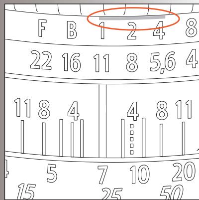
Warning mark
34
You will find an orangeline on the shutter speed scale above the 1, 1/2, and 1/4s settings. This is to warn you of possible exposure errors as detailed above. The auxiliary shutter will terminate the exposure prematurely if you relax the pressure on the button too soon.
Listen to the buzzing sound of the delay escapement in the lens' shutter and maintain the pressure on the release button until the sound stops.
Exposure values
35
The aperture and shutter speed combination set opposite the central lens index determines the exposure. Every combination of shutter speed/ aperture has an equivalent exposure value (EV) which you can read and set against the red EV index on the right hand side of the lens.
Interlocked shutter speed / aperture
36
If you want to change the shutter speed or aperture while still keeping the same shutter speed/ aperture combination (EV), you can interlock
the speed and aperture setting rings by holding down the interlock button which is on the right of the aperture scale. When interlocked, the rings move together, increasing or decreasing the aperture to compensate for a decrease or increase of speed respectively.
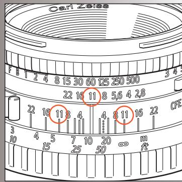
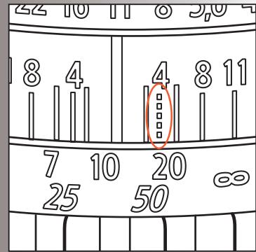
Focusing and depth of field
37
The focusing ring is closest to the camera body. It has a knurled rubber grip and engraved distance scales in feet and metres. Focus the lens by rotating the focusing ring until you obtain a sharp image of the subject in the viewfinder.
The distance between the subject and the film plane is read off the focusing ring's distance scale opposite the central lens index.
Objects closer or further away than the selected distance will be sharp, within certain limits. The limits of this field of sharp focus - depth of field - vary with the aperture.
The depth of field available at any given aperture can be read off the depth of field scale on both sides of the central index. As an example, the illustration indicates how to read the depth of field scale at an aperture of f/11. The depth of field will in this case range from ca 4.3 metres to ca 20 metres.
Depth of field preview
38
Depth-of-field can be visually checked on the focusing screen. The diaphragm can be stopped down to the preset aperture from its normally wide open position simply by pushing the
depth-of-field preview lever downwards until it locks.
To reopen the diaphragm, depress the lower part of the lever.
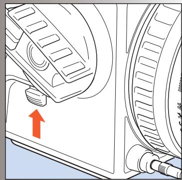
Pre-release and cable release
Considerable efforts have been made to reduce camera vibrations caused by moving parts in the exposure sequence. However, if you wish to avoid these vibrations completely, you can pre-release the mechanism by pushing the pre-release button upwards. This causes the following sequence:
- The mirror folds up
- The shutter closes and remains closed
- The diaphragm closes to its preset aperture
- The auxiliary shutter opens
When you subsequently press the release button, only the shutter then operates at the preset speed.
As shown in the illustration, you can also attach a cable release to further reduce vibrations.
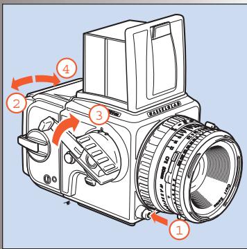
Double exposure
40
As the camera has been designed to prevent accidental double exposure you will have to carry out the following procedure in order to make multiple exposures on the same frame:
- Depress the main release button and make the initial exposure.
2.Insert the magazine slide and remove the magazine.
39
3. Wind the camera with one full revolution of the winding crank.
4.Replace the magazine and remove the slide. The unit is now ready to make a second exposure on the same frame. You can make additional exposures in the same manner.
Flash synchronization
41
The C series lenses have built-in leaf shutters with speeds from 1s to 1/500s and B. Flash synchronization occurs at full shutter opening via the PC flash terminal. Suitable electronic flash units can be used at all shutter speeds from 1s -1/500s as well as B.
Please see under 'Accessories' the sections on the use of a Hasselblad D-Flash 40 and a Hasselblad Flash adapter SCA 390 with a 503CW.
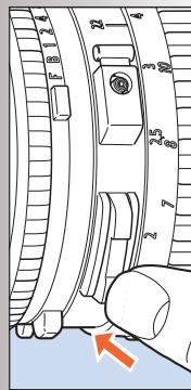
Infrared photography
42
Infrared (IR) rays (wavelengths longer than 800nm ) form an image on a plane further away from the lens than the image plane for visible light. To compensate for this difference you have to align the chosen distance against the red IR index and not the normal central index. Proceed as follows:
- Focus as usual on the focusing screen.
- Note the distance on the focusing scale that is opposite the central index line.
- Now rotate the focusing ring to set this distance opposite the red IR index line instead of the central index line.

Please observe the special information that came with your IR film regarding magazine loading, film development, etc.
The Viewfinder System
The 500 series cameras are supplied with a light, compact and foldable viewfinder, providing a through-the-lens laterally reversed image. It is easily interchangeable with alternative viewfinders including the prism finders, which produce a laterally corrected image. Please see 'Accessories' for further details about prism finders.
The focusing hood on the standard viewfinder has a built-in 4.5x magnifier for accurate focusing and this can easily be changed to suit individual eyesight.
The 500 series cameras are equipped with an Acute-Matte D focusing screen which produces an exceptionally bright and sharp image. While this normally covers most needs, the Hasselblad system offers a range of alternative screens for various specific applications.
Each item is easily and quickly interchangeable without the need for special tools or facilities.
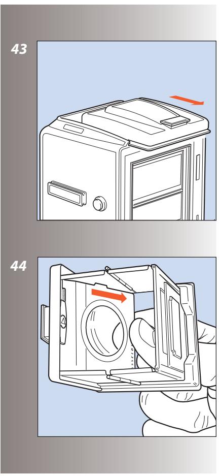
Changing the focusing hood or viewfinder
43
To remove the focusing hood so as to attach any other viewfinder in the Hasselblad system, proceed as follows:
- Detach the magazine.
2.Fold down the focusing hood to protect it from damage and remove it by sliding it to the rear in its guide slots.
3.Slide the replacement viewfinder into the slots and push it forward until it stops.
When fully inserted the viewfinder is retained in position by a spring-loaded catch until you have reattached the magazine.
Changing the magnifier
44
Mounted lenses with dioptre correction from +3 to -4 are available, and are easily interchanged as follows:
- Remove the focusing hood from the camera and open it by lifting the lid.
- Release the magnifier by pushing the catch to the right.
3.Push the magnifier halfway back down to its folded position.
4.Grip the lower edge of the magnifier plate (through the underside of the hood), and pull firmly. - Keep the plate holder halfway down and insert the replacement lens plate with the printed side up. Fold the hood down and replace on the camera.
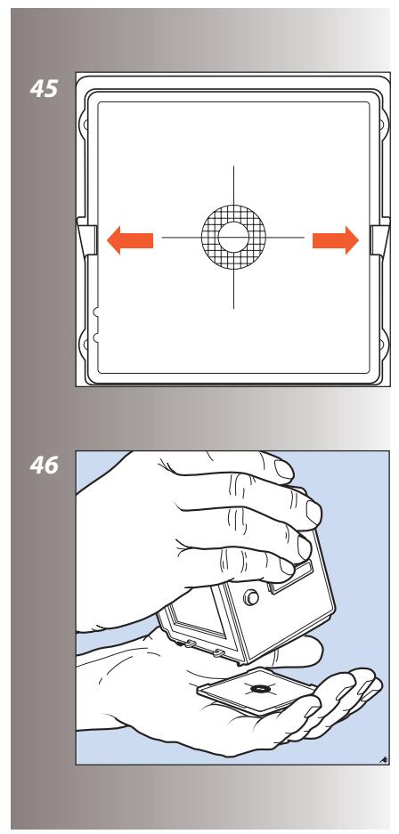
Changing the focusing screen
45, 46
1.Detach the magazine and viewfinder.
2.Push the two screen clips to the side into their recesses.
3. Place your hand over the screen, and invert the camera. The screen will now drop into your hand.
4.Insert the replacement screen, ensuring that the smooth flat side is uppermost and the sharp-edged corners down. Ensure that all four corners of the screen are positively seated on their supports.
You need not return the screen latches. This is done automatically when the viewfinder is replaced.
Should the screen refuse to drop out by itself, ensure that the camera is fully wound, remove the lens and check that the mirror is in the down position. Put a finger through the lens mount and push gently on the screen from underneath, preferably with a soft cloth between the screen and the finger.

Do not immerse the screen in water, or use any kind of cleaning fluid.

Do not use hot air to dry the screen if it becomes damp.
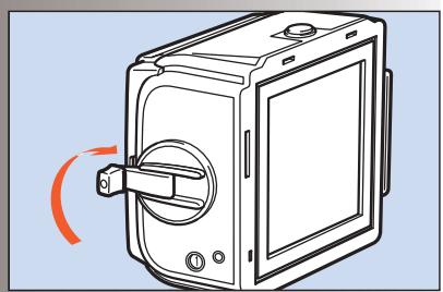
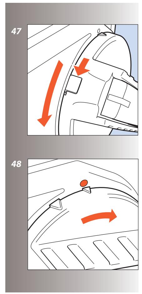
Winding crank (503CW only)
47, 48
The winding crank on the 503CW can be removed. Push the catch lever downwards while rotating the crank counter-clockwise and pull
the crank straight out from the shaft. To attach it, align the small triangular index mark against the red dot on the camera body. Keep the crank pushed against the camera while turning it clockwise until the larger triangular mark is aligned with the red dot where it will click into position.
Accessories
All accessories included in the present Hasselblad Product Catalog can be used with the 500 series cameras (when not specifically noted otherwise), except the FE-type lenses. As these cameras are further development of previous models, they feature certain improvements and differences in construction. This means that certain older and now discontinued accessories cannot be used and any forced attempt at mounting them may damage your equipment, so please check carefully before trying.
Figure 63 shows the wide range of accessories presently available within the Hasselblad System for the 501CM and 503CW cameras. Please refer to the Hasselblad Product Catalogue, available from your Hasselblad dealer, for complete and up to date information, or visit our website - www.hasselblad.com.
For a general overview, 'The Hasselblad Manual' by Ernst Wildi is recommended. Here you will find detailed descriptions of accessories as well as their practical application so you can easily make a judgement about suitability for your type of work.
Accessory rail
Both cameras have an accessory rail on the left hand side for the spirit level and the adjustable flash shoe (for small flash units).
Flash
Any flash unit can be connected to the 500 series cameras via the PC flash terminal on the lens for manually controlled flash exposure, see 'Flash synchronization' above - illustration 41. The shutter and flash sync speeds are up to 1/500s .
Automatic flash control, or dedicated flash, is possible with the 503CW and is provided by the camera's built-in flash sensor and electronics (TTL/OTF) that measure the light reflected from the central portion of the film; a circle with a diameter of 40~mm . The metering system is connected to a selector for setting film speed.
When a Hasselblad D-Flash 40 is attached - or an SCA 300 compatible flash unit is connected through an SCA390 flash adaptor - the system controls the flash unit and cuts off the flash when the exposure is correct. Under the left hand edge of the focusing screen an indicator
light shows when the flash is ready to be operated and also confirms if the flash output was sufficient to give a correct exposure. The flash unit powers the camera's electronics and also the flash adaptor, when that is used.
D-Flash 40 (503CW only)
The D-Flash 40 utilises the TTL/OTF features of the 503CW for dedicated operation. It is very simple to operate, with adjustable positioning and a guide number of 40 / 137 (m/ft) and 33/110 (m/ft) in the wide-angle position.
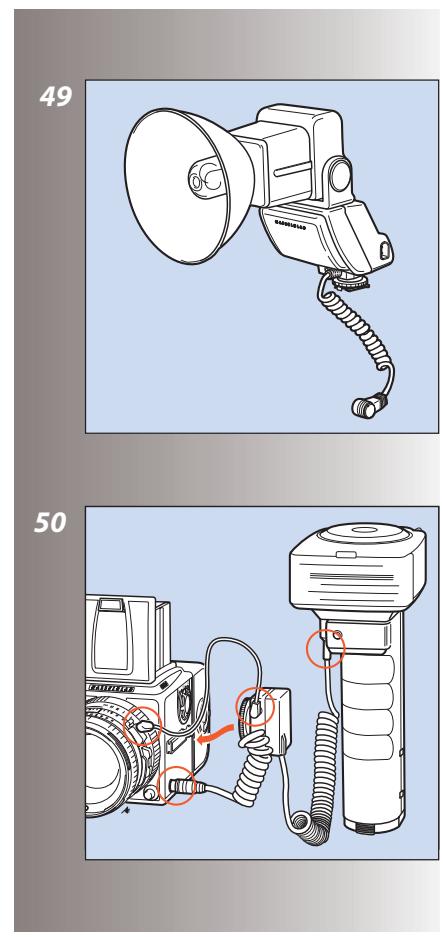
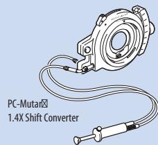
Attaching a Hasselblad flash adaptor SCA 390 - (503CW only)
50
For hand-held flash units, the adaptor is attached as in the illustration:
- the 6-pole contact from the spiral cord is connected to the camera's dedicated flash connector.
- the sync cord is connected from the adaptor to the PC flash terminal of the lens.
- the connecting cord is attached to the hand-held unit
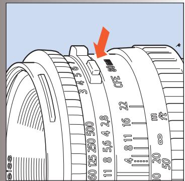
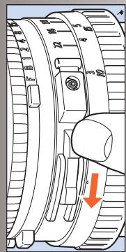
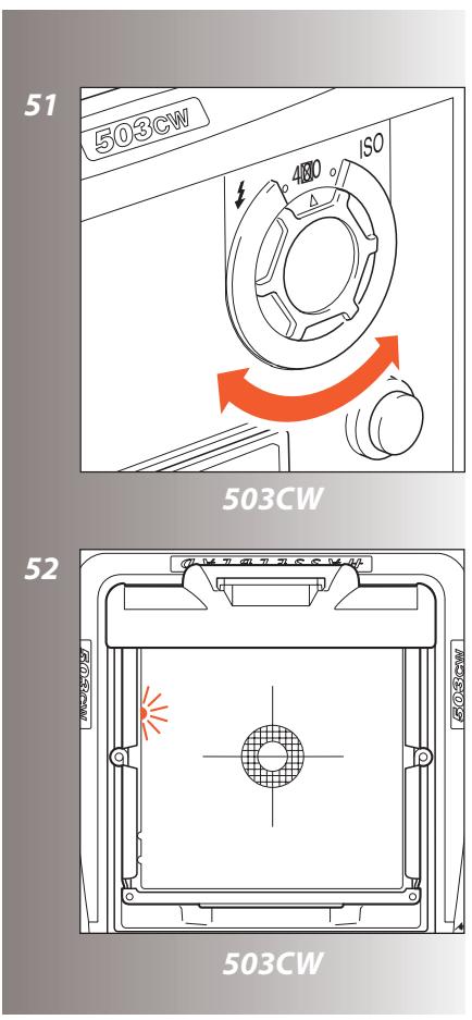
Setting the film speed - (503CW only)
51
The film speed is set via the ISO selector. This is marked in ISO/ASA settings from 64 - 4000 (see fig 58 for ISO/ASA - DIN equivalent table). Certain films require compensation for differences in reflection. In these instances, the compensation is made by changing the film speed
selector setting. The amount of compensation has to be determined by experiment.
Please refer to your flash unit's operating instructions for more information about other functions when using the D-Flash 40, automatic flash light metering that conforms to System SCA flash photography with flash sensors, or with non-automatic flash units.
Viewfinder indicator - (503CW only) 52
Flash operation and flash battery-check are indicated by a red light, located under the left edge of the focusing screen. It is operative only when a dedicated flash is connected to the TTL socket. It indicates three separate states as described below.
Ready signal
A steady red light indicates that the flash unit is charged and ready to be fired. Absence of any signal indicates the need for fresh batteries.
Confirmation signal
A flashing red light occurring for just over a second immediately after exposure confirms that the light output was sufficient for a proper exposure. It then remains dark until the flash unit has recharged. The steady red light will then reappear indicating operative status again. The time of reappearance however may vary according to the condition of the batteries.
No result signal
Absence of the flashing confirmation signal after exposure indicates that the flash emitted was not sufficient for correct exposure. The ap
erture must then be opened more or the flash distance to the subject reduced. Changing to a faster film is also a possibility.
The Rear cover MultiControl (51070) - supplied - has a flash exposure control facility in the form of a grey panel on the inside. It simply replaces the magazine temporarily to provide an inexhaustible standard reference for flash exposure testing at no cost in terms of film. It is particularly useful when exposing films with a narrow exposure latitude, such as transparency film.
The camera's flash control system reads light reflected directly off the film plane, and is governed by the reflective characteristics of the film emulsion that the grey panel simulates.
When using a dedicated flash unit proceed as follows:
- Set up the flash unit with the camera normally, using the TTL/OTF function setting.
- Replace the magazine with the Rear cover MultiControl.
3.Make a test exposure.
4.Note the exposure indications in the viewfinder. If warned by the camera for underexposure then make the appropriate changes by altering the aperture or flash-to-subject distance. Make further tests until the camera indicates correct exposure. - Replace the Rear cover MultiControl with a magazine and proceed as normal, using the adjusted exposure settings.
Although this method should provide a generally acceptable exposure, adjustment of the settings may still be required to obtain a result that suits your personal preference. See flash unit's instruction manual for more information.
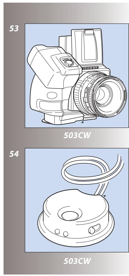
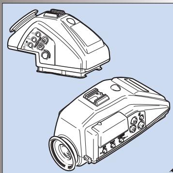
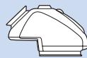
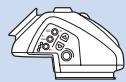
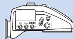
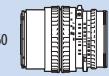
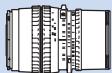
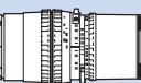
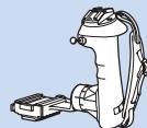
Winder CW- (503CW only)
53, 54
The Winder CW is a compact, ergonomically designed unit providing not only a motor drive facility but also a comfortable and robust grip for the Hasselblad 503CW.
It features single exposure, continuous exposure as well as multi-exposure modes. Remote control is achieved by a simple release cord or by the unique infrared transmitter - the Hasselblad IR Remote control (fig. 54). Both provide considerable freedom, with the IR Remote control offering an extra remote mode choice facility. Each winder is governed by a unique code from the IR Remote control so there is no risk of controlling other cameras unintentionally. However, one IR Remote control can control several cameras at the same time if desired.
As the winder is set close to the camera body, it produces stability and balance for optimum hand held efficiency - the perfect requirement for vertical 6x4.5 shots. A removable strap offers extra security and is adjustable to suit personal requirements.
See the Winder CW instruction manual for further details.
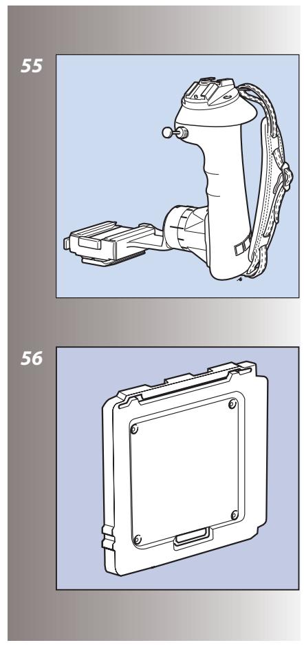
Snap-lock flash grip
Primarily a portable flash unit support but also acts as an ergonomic camera-grip. It is fully adjustable and can be rapidly detached for flash-off-camera shooting. It also features an Integrated Quick coupling S for optimal rapid use.
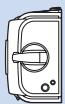
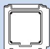
Rear cover MultiControl
56, 57
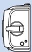
The Rear Cover MultiControl ( 51070) - supplied - not only provides protection for the camera body when a magazine is not attached but also provides flash check facility for cameras featuring TTL/OTF (described above) and a vignetting check facility.
The vignetting check is useful when any filter, attachment or lens shade is used to ensure the optimum from the accessory without risking the possibility of inadvertant vignetting.
With the cover in position you can see the so-called exit pupil of the lens through the small holes in the cover. A vignetting free lens has an exit pupil the exact shape of the lens aperture. At maximum aperture there is slight vignetting with all lenses but at f/11 to f/16 the majority of lenses are free of vignetting.
Corner illumination is dependent on the size of the exit pupil. If the filter or lens shade extends too far, the area of the exit pupil diminishes. The shading effect of a professional lens shade, for example, is optimal when it has been extended as far as possible without causing any visible
corner vignetting. The amount of this extension is dependent on both the working aperture and the focusing distance for the lens used.
Use the following method when any kind of lens accessory is in place and you want to ensure a result free from vignetting:
- Fit the accessory. Remove the film magazine but do not attach a Rear Cover MultiControl just yet.
2.Set the shutter on a CF/CFi/CFE lens at the 'F' position and pre-release the camera to open both the lens shutter and the auxiliary shutter. C/CB lens shutters should be set at 'B' and a B exposure made. Use a cable release to lock the released position.
3.Look at the lens exit pupil. Use the stop-down button and change the aperture noticing as you do so the changes in the size of the exit pupil.
4.Look now at an angle roughly in a line from the exit pupil to one corner of the camera back opening. This helps in finding the exit pupil again when the RCMC is attached, which can be troublesome with wide-angle lenses in particular. - Attach the RCMC and observe the exit pupil again.
- Select the working aperture and stop down manually.
- Set the approximate focusing distance.
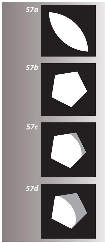
8.See the diagrams for a fuller explanation of what you can now see through one of the holes, and act accordingly.
In diagrams 57 A - D all exit pupils are viewed from the image corners.
Diagram A
Exit pupil for a wide-open lens
Diagram B
Exit pupil for a vignette-free stopped down lens
Diagram C
Exit pupil for a slightly vignetted lens (no visible effect on the image)
Diagram D
Exit pupil for a vignetted lens (clearly visible effect on the image)
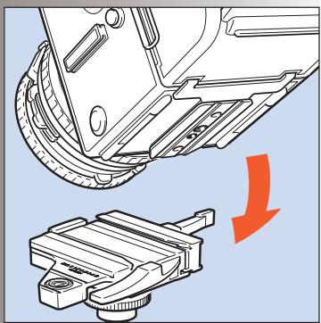
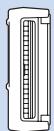
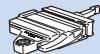
Tripod quick-coupling S
58
The coupling plate on the bottom of the camera body has both a 1/4 in. and a 3/8 in. tripod thread. It also fits the useful and reliable Hasselblad Tripod Quick-Coupling S (45144). This facilitates rapid and repeatedly accurate attachment and removal of the camera from a tripod or support.
Viewfinders
59
Certain individual requirements and applications demand more from the viewfinder image than the conventional set up provides. Magnifying hoods and focusing hoods are available as well as a range of prism viewfinders, including advanced TTL metering models.
Meter prism viewfinder adjustments
The Hasselblad meter prism viewfinders measure the light level on the focusing screen. They are calibrated at the factory to give an accurate reading with one particular type of screen. If that focusing screen is replaced with another type which provides a different light level under the same ambient conditions, the meter has to be adjusted to compensate for the difference. Towards the end of this manual you will find a table that shows the adjustments that should be made with meter prism viewfinders to compensate for the light level differences with the different focusing screens.
Please refer to your viewfinder's operating instructions for further information about other functions.
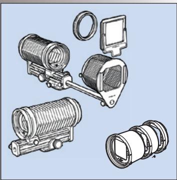
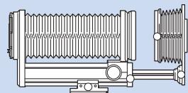
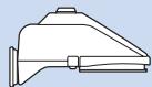
Professional lens shade
60
The Proshade 6093T (40739) provides the ultimate in flare and stray light reduction. It is particularly useful if you have a number of lenses as it fits virtually all lenses in the range. It is supplied with a Proshade mask 6093/250 (40312) which provides further control for longer lenses when the Proshade is fully extended. See section 56 above on Rear Cover MultiControl for combined use to produce optimum shading control. The Proshade also functions as a gelatine filter holder.
Close-up accessories
Four fully automatic extension tubes and an automatic bellows extension are available for close-up work.
61
Action required when combining prism meter viewfinders with Acute-Matte D focusing screens
| Screen type | PME3 PME5 PME51 | PME | Integral | Spot Metering PME90 | Spot Metering PME45 |
| 42204 | No restrictions | The exposure should be increased by 1 EV value.* Note: 1.4X and 2X converters require test exposures. | The exposure should be reduced by 1 EV value when using lens / teleconverter combinations which reduce the effective aperture to f/8 or smaller.** | Lenses without teleconverters: No restrictions | |
| 42207 | Lenses with teleconverters: The exposure should be reduced by 1 EV (*) when the combined aperture is f/7 or smaller. | ||||
| 42210 | |||||
| 42213 | |||||
| 42215 | No restrictions | The exposure should be increased by 1 EV value.* Note: 1.4X and 2X converters require test exposure | No restrictions within the f/2 - f/5.6 range. Note: Not recommended for lenses or lens / converter combinations where the maximum effective aperture is smaller than f/5.6 | Will work for lenses only, and in the f/2 - f/4 range provided the split image line is in the horizontal position. | |
| 42217 | |||||
| 42219 |
- The easiest way to increase the exposure by one EV value is to reduce the ISO setting to half the film speed value as indicated on the film package, e.g. ISO400 film is set at ISO200, ISO100 film is set at ISO50, etc.
**To reduce the exposure by one EV value, increase the ISO setting to double the film speed value as indicated on the film package, e.g. ISO400 film is set at ISO800, ISO100 film is set at ISO200, etc.

Incident light metering can be used without restrictions since it is independent of the focusing screen
Troubleshooting
Your camera is built to give long and trouble-free service, especially when you follow the maintenance and care advice at the end of this manual. If however you encounter any operating difficulties because you are not familiar with the Hasselblad camera system, the following table may help to resolve them. If the problem persists and the camera is still under guarantee, you should contact your Hasselblad dealer. If the guarantee has expired, you should contact a Hasselblad Authorised Service Center for advice. You can obtain the address of your nearest service centre from your dealer, distributor, our
| PROBLEM | POSSIBLE CAUSE | REMEDY |
| You cannot operate the exposure release button | ·The magazine slide is still in place ·The film is finished ·The camera is not rewound | ·Remove the magazine slide completely ·Load a new film ·Wind the camera |
| There is no image on the focusing screen | ·The camera is in the pre-released or released position ·The lens cap is still in place | ·Complete the camera release and rewind the camera ·Remove the lens cap |
| You cannot remove the front protective cover | ·The camera is in the pre-released or released position | ·Complete the camera release and rewind the camera |
| You cannot attach the lens | ·The lens is in the released position ·The camera body is in the pre-released or released position | ·Wind the lens ·Complete the camera release and rewind the camera |
| You cannot remove the lens | ·The camera body is in the pre-released or released position | ·Complete the camera release and rewind the camera |
| You cannot remove the magazine | ·The magazine slide is not fully inserted | ·Push the magazine slide until it positively stops |
Technical Specifications and Equipment – 501CM/503CW
| Camera type: | Single lens reflex camera with 6 x 6 cm (2 1/4 x 2 1/4 in) max. film size. Interchangeable lenses, film magazines, viewfinders, and focusing screens. |
| Design: | Mechanical, with an aluminum alloy camera body shell cast in one piece. |
| Viewfinder: | Folding focusing hood interchangeable with reflex viewfinder, prism viewfinders with or without built-in light meter, or magnifying hood. |
| Film advance: | 501CM: Manual advance. Simultaneous shutter winding. 503CW: Manual advance or motor driven with Winder CW. Simultaneous shutter wind-ing. Winder CW winding time: 1.05 s, approx. 0.8 frames/sec in continuous mode. |
| Flash control: | 503CW only: TTL/OTF-metering. ISO 64-4000 with flash adaptors SCA390 for con- nection with flash units from the SCA 300 systems. Metering area within 40 mm diameter in the centre of the image area. |
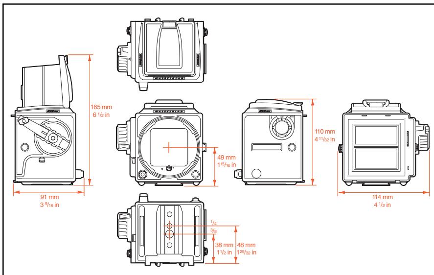
| Tripod coupling: | 1/4 in. and 3/8 in. socket threads and base plate for quick coupling attachment. |
| External dimensions: | Camera body only - see fig 63. Camera body with Planar CFE 2.8/80 mm lens, film maga-zine A12-6x6 and focusing hood: 180mm L x114mm W x110mm H (7x4½ x4½") |
| Weight: | Camera body only: 0.6 kg (1 .3 lb). Camera body with Planar CFE 2.8/80 mm lens and A12 film magazine: 1.5 kg (3.3 lb). |
| Focusing screen: | Hasselblad Acute-Matte D* focusing screen |
Equipment Care, Service and Guarantee
EQUIPMENT CARE
A Hasselblad camera is designed to withstand the rigours of professional use in most environments. To avoid the possibility of damage however, it should be protected from the following:
Extremes of temperature: High temperatures can have an adverse effect on both film and equipment. Try to avoid frequent and severe temperature changes. Be particularly careful in humid environments. Allow the equipment to acclimate before assembly. Try to ensure the storage conditions in such environments are as dry as possible.
Dust and grit: Take care to prevent dust and grit from getting into your equipment. In coastal areas take measures to protect your equipment from sand and salt water spray. Dust on the lens glass and focusing screen can be removed with a blower brush or very soft lens brush if necessary. Smears on the lens glass should be treated with great caution. In some cases they may be removed with a high quality lens cleaning solution on a tissue but be careful not to scratch the lens or touch any of the glass surfaces with your fingers. If in any doubt, do not attempt to clean lens glass surfaces yourself but allow a "Hasselblad Authorized Service Center" to treat them.
Impact: Your equipment can be damaged by severe physical shocks so practical protective precautions should be taken. Some form of protective case or camera bag is advised for transportation.
Loss: Hasselblad equipment is much sought after and you should take obvious steps to prevent theft. Never leave it visible in an unattended car, for example. Separate and specific camera insurance cover should be considered by professional users.
SERVICE
Return your equipment to a service centre for occasional checking and preventive maintenance to ensure optimal reliability. If your camera is used constantly and intensively, periodic check-ups every six months are recommended at one of the "Hasselblad Authorized Service Centers". They have the expert staff and specialised equipment necessary to ensure that your equipment remains in perfect working order.
GUARANTEE
Provided that you bought your equipment from an authorised Hasselblad outlet, it is covered by an international guarantee for one year. The guarantee document and a registration card are supplied with the camera. Keep the guarantee document carefully, but fill in the registration card and return it to your Hasselblad distributor.
501cm & 503CW
501cm & 503CW
3
6
4
7
5
8
9
10
11

12
13
14
25
28
31
33
26
29
32
34
35
37
39
41
36
38
40
42
58
60
59
61
ASA 64 . 100 . . 200 250 . 400 . . 800 . . 1600 ISO
DIN 19 20 21 22 23 24 25 26 27 28 29 30 31 32 33

503cw
Winder CW
501CM & 503CW
E12CC
E12
A12

PM45
PME45


6x6cm
E24
A24

Softars


60

60

070
070


093
093
Pola
63
PME9C
PM90

CF30

CFE40II

CFi 50

CFi60


CFE180

CFi 100


060
Teleconverter APO 1.4XE

Teleconverter 1.4XE
Proshade 6093T
Converter 2XE


CFE 350Sa