
AMA 1200 - Amplificateur PEAVEY - Notice d'utilisation et mode d'emploi gratuit
Retrouvez gratuitement la notice de l'appareil AMA 1200 PEAVEY au format PDF.

| Type de produit | Console de mixage amplifiée |
| Marque | PEAVEY |
| Modèle | AMA 1200 |
| Puissance de sortie (ampli unique) | 250 W RMS sous 4 Ω, 150 W RMS sous 8 Ω |
| Puissance de sortie (deux amplis) | 250 W RMS sous 4 Ω par canal, 150 W RMS sous 8 Ω par canal |
| Impédance de charge minimale des enceintes | 4 Ω par canal |
| Alimentation | 120 V AC, 60 Hz, 800 W max |
| Consommation maximale | 800 W |
| Fusible | Type et valeur identiques à ceux d'origine (voir étiquette) |
| Nombre de canaux d'entrée | 12 (d'après le schéma, mais non précisé explicitement) |
| Égalisation par canal | Aigus ±15 dB à 10 kHz, Médiums ±12 dB à 650 Hz, Graves ±15 dB à 50 Hz |
| Égaliseur graphique intégré | 9 bandes (63 Hz à 16 kHz) ±12 dB |
| Envois monitoring | 2 (Monitor A et B) |
| Alimentation fantôme | 15 V DC, commutable par canal |
| Entrées micro | XLR symétrique, impédance 3 kΩ |
| Entrées ligne | Jack 6,35 mm, impédance 100 kΩ |
| Sorties enceintes | 2 x Jack 6,35 mm parallélisés par canal |
| Réponse en fréquence (préampli) | ±0, -3 dB de 20 Hz à 20 kHz (EQ plat) |
| Distorsion harmonique totale (ampli) | < 0,1 % typique, < 0,3 % max de 100 mW à 150 W RMS |
| Protection | Court-circuit, circuit ouvert, surchauffe, fusibles primaires |
| Refroidissement | Ventilateur à convection assistée (ne fonctionne qu'en cas de besoin) |
| Entretien | Nettoyer avec un chiffon humide ; éviter les liquides et les objets dans les orifices |
| Sécurité | Interrupteur de masse (non fonctionnel sur les modèles 220/240 V) ; utiliser des protecteurs auditifs en cas de niveaux sonores élevés |
| Garantie | 1 an pour le premier acheteur (États-Unis) |
FOIRE AUX QUESTIONS - AMA 1200 PEAVEY
Questions des utilisateurs sur AMA 1200 PEAVEY
0 question sur cet appareil. Repondez a celles que vous connaissez ou posez la votre.
Poser une nouvelle question sur cet appareil
Téléchargez la notice de votre Amplificateur au format PDF gratuitement ! Retrouvez votre notice AMA 1200 - PEAVEY et reprennez votre appareil électronique en main. Sur cette page sont publiés tous les documents nécessaires à l'utilisation de votre appareil AMA 1200 de la marque PEAVEY.
MODE D'EMPLOI AMA 1200 PEAVEY
OPERATING INSTRUCTIONS

Intended to alert the user to the presence of uninsulated "dangerous voltage" within the product's enclosure that may be of sufficient magnitude to constitute a risk of electric shock to persons.

Intended to alert the user to the presence of important operating and maintenance (servicing) instructions in the literature accompanying the product.
CAUTION: Risks of electrical shock — DO NOT OPEN
CAUTION: To reduce the risk of electric shock, do not remove cover. No user serviceable parts inside. Refer Servicing to qualified service personnel.
AMA TM 1200
POWERED MIXING
CONSOLE

PEAVEY®
A R C H I T E C T U R A L A C O U S T I C S ®
1
2
4
5
6
7
8
9
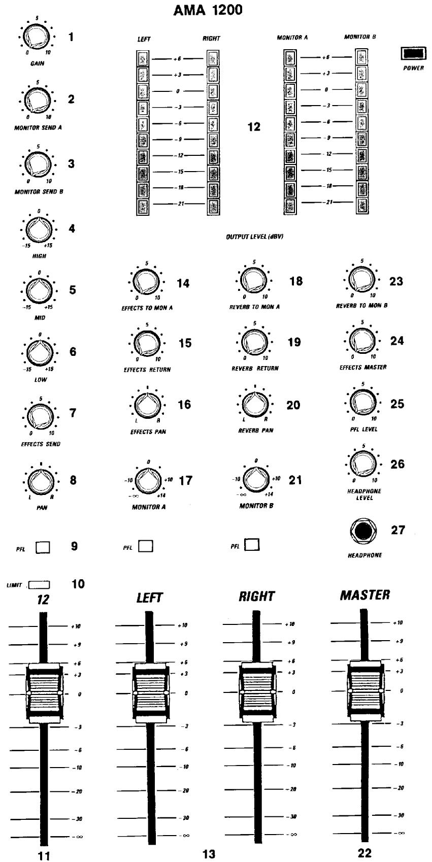
GAIN (1)
Varies the gain of the channel input stage to allow a wide input dynamic range. Proper adjustment of the input gain is aided by observance of the LIMIT LED.
MONITOR (A) SEND (2)
Controls the channel monitor "A" mix level. It is independent of all channel functions except GAIN, allowing adjustment of the "house" mix without affecting the monitor mix.
MONITOR (B) SEND (3)
Controls the channel monitor "B" mix level. It is independent of all channel functions except GAIN, allowing adjustment of the "house" mix without affecting the monitor mix.
HIGH (4)
An active tone control (shelving type, ±15 dB) that varies the high frequency boost or cut.
MID (5)
An active control capable of 12 dB boost or cut at 650 Hz.
LOW (6)
An active tone control (shelving type, ±15 dB) that varies the low frequency boost or cut.
OPERATION NOTE
Excessive EQ boost, especially of the low frequencies, increases the possibility of speaker damage, and sacrifices valuable headroom.
EFFECTS SEND (7)
Sets the channel reverb drive level. When an effects device is connected in the effects patch loop, this control determines the channel signal level available to drive the external effects device. Works together with the master effects and reverb controls.
PAN (8)
For stereo operation PAN is used to mix the channel to Left, Right, or in between in the “stereo image”. For Mono (2x1) operation PAN enables channel assignment to the Left or Right submasters.
PFL (9)
Allows cueing of any channel or combination of channels instantly through headphones connected to the headphone jack (master section). All channel functions (except fader) may be monitored via the channel PFL system.
LIMIT LED (10)
Indicates when the signal level in the channel is too high. It illuminates when the channel signal reaches approximately 15 dBV.
OPERATION NOTE
Illumination indicates clipping (distortion) in the channel. Proper channel adjustment will allow operation without lighting the LED. Adjust the Gain, EQ and Level so that the LED does not flash during operation. The sampling for status indication is taken at three critical points: after the input amp and Out/In insertion point; equalization; and final channel gain stage.
CHANNEL LEVEL SLIDER (11)
Determines the level of the channel. Calibration is in dB and level is variable from - infinity (off) to +10 dB. This should be operated near the "0 dB" (unity gain) indicator whenever possible to assure an optimum balance between channel noise and headroom.
OPERATION NOTE
Sometimes it may be necessary to operate the slider at other than this optimum setting.
Example: If the channel need not be as loud as the other channels, the slider may be set lower than 0 dB. This yields lower noise and a visual indication of the channel's relative level. Should more level be needed, it can be achieved with the slider, preventing readjustment of the critical input gain, which would also affect the Monitor Sends.
LED ARRAYS (12)
Four calibrated 10-segment LED arrays are provided to visually indicate the levels of the mixes selected.
LEFT/RIGHT SUBS (13)
These are the masters for all channels and determine the overall main or “house” mix levels.
EFFECTS TO MONITOR A (14)
Allows the effects return to be assigned to Monitor A.
EFFECTS RETURN (15)
When an outboard effects device is connected into the effects patch loop, this control regulates the level of the effect in the Left or Right mix. Must be used together with Effects Pan.
EFFECTS PAN (16)
Allows the effects return signal to be assigned to Left Main, Right Main or both.
MONITOR (A) MASTER (17)
This is the master for all channel monitor sends and determines the overall monitor mix level.
REVERB TO MONITOR A (18)
Allows the reverb effect to be assigned to Monitor.
REVERB RETURN (19)
Controls the reverb effects supplied to the Left and Right Mains. This must be used together with Reverb Pan.
REVERB PAN (20)
Allows the reverb effect to be assigned to Left Main, Right Main or both.
MONITOR (B) MASTER (21)
This is the master for all channel monitor sends and determines the overall monitor mix level.
MASTER (22)
Controls the overall mix level when the mixer is operated in the mono configuration (2x1). "Master" is the combination of the Main Left and Right signals and the Master Aux. In.
REVERB TO MONITOR B (23)
Allows the reverb effect to be assigned to Monitor B.
EFFECTS MASTER (24)
Determines the effects level supplied to the internal reverb and the Effects Out jack.
PFL LEVEL (25)
Controls the level for any "pre fade listen" (PFL) source, selected on the mixer. One or more PFL switches must be engaged before this control is active.
HEADPHONE LEVEL (26)
Adjusts the left and right signal level to the headphone jack. Signal taken pre the left and right main sliders. (PFL's for L & R must be activated.)
OPERATION NOTE
When no PFL switches are activated, the headphone level selects monitor "A" and monitor "B" outputs.
HEADPHONE JACK (27)
Connecting stereo headphones here will allow cueing of all PFL functions or signals from left and right mains from Monitor "A"/Monitor "B".
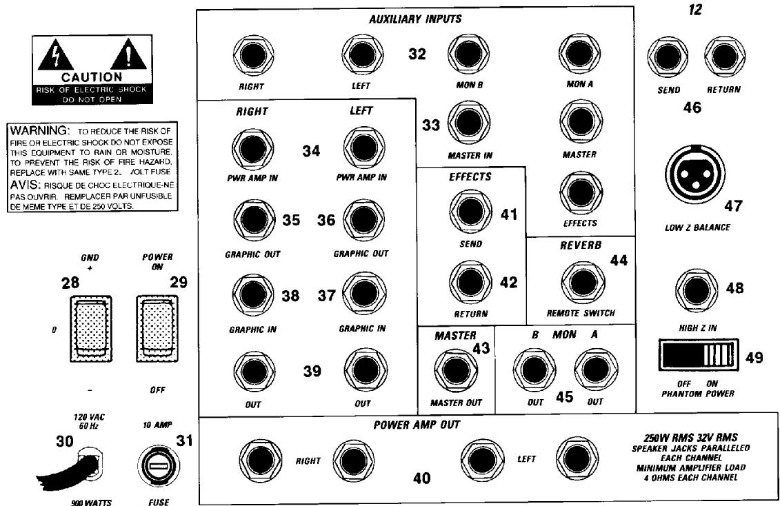
GROUND SWITCH (28)
Three position rocker-type switch which, in most applications, should be operated in its center or zero position. There may be some situations when audible hum and/or noise will come from the loudspeaker. If this situation arises, position the ground switch to either positive or negative (+ or -) or until the noise is minimized.
NOTE: Should the noise problem continue, consult your Authorized Peavey Dealer, the Peavey Factory, or a qualified service technician. THE GROUND SWITCH IS NOT FUNCTIONAL ON 220/240 VOLT MODELS.
POWER SWITCH (29)
Depress to "On" position to turn on.
LINE CORD (120V PRODUCTS ONLY) (30)
For your safety, we have incorporated a 3-wire line (mains) cable with proper grounding facilities. It is not advisable to
remove the ground pin under any circumstances. If it is necessary to use the equipment without proper grounding facilities, suitable grounding adaptors should be used. Less noise and greatly reduced shock hazard exists when the unit is operated with the proper grounded receptacles.
FUSE (31)
The fuse is located within the cap of the fuseholder. If the fuse should fail, IT MUST BE REPLACED WITH THE SAME TYPE AND VALUE IN ORDER TO AVOID DAMAGE TO THE EQUIPMENT AND TO PREVENT VOIDING THE WARRANTY. If the amp repeatedly blows fuses, it should be taken to a qualified service center for repair.
WARNING: THE FUSE SHOULD ONLY BE REPLACED WHEN THE POWER CORD HAS BEEN DISCONNECTED FROM ITS POWER SOURCE.
AUXILIARY INPUTS (32)
May be used to patch an external signal into any of the mix buses. These inputs are primarily for patching in an auxiliary mixer to gain more channels.
MASTER INPUT (33)
Provides "insert" point before master level control. This jack is the switching type and "breaks" the signal chain at this point.
POWER AMP INPUT L/R (34)
Provides "insert" points to both internal power amps at their respective inputs. These jacks are the switching type and "break" the signal chain at this point.
GRAPHIC R OUT (35)
Provides output from Graphic R only.
GRAPHIC L OUT (36)
Provides output from Graphic L only.
GRAPHIC INPUT L (37)
Provides "insert" point at the input to Graphic L. This jack is the switching type and breaks the signal chain at this point.
GRAPHIC INPUT R (38)
Provides "insert" point at the input Graphic R. This jack is the switching type and breaks the chain at this point.
LEFT OUT/RIGHT OUT (39)
These inputs are from the Left and Right Mains and the levels are adjusted by the Left and Right controls.
SPEAKER OUTPUT JACKS (40)
Two parallel 14 " jacks are provided at the output of each power amplifier. Minimum speaker load impedance is 4 ohms for each amplifier.
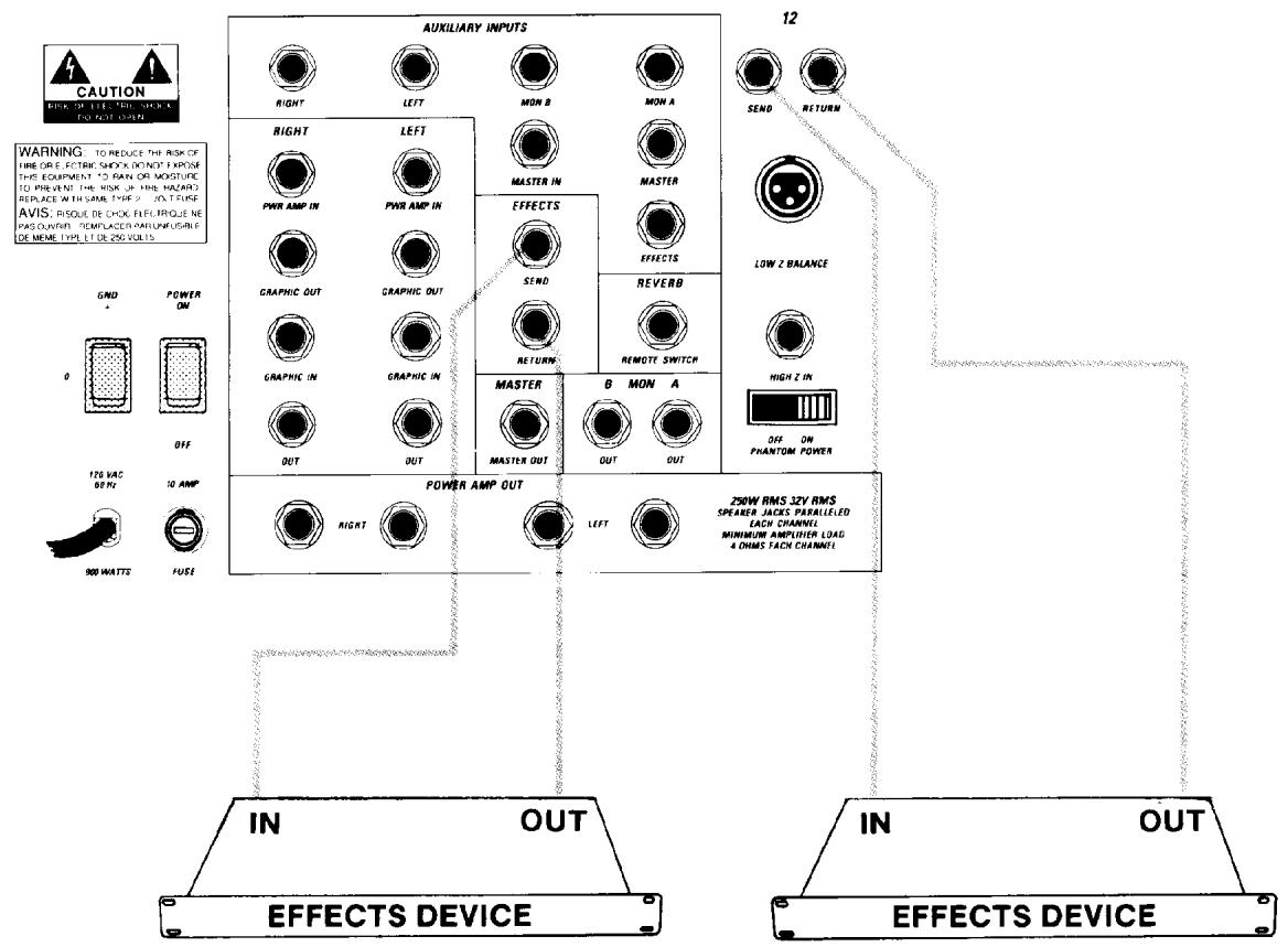
EFFECTS OUT (41)
Output for supplying signals to external effects or signal processing equipment.
OPERATION NOTE
Level is adjusted by the Effects Send and Effects Master controls.
EFFECTS RETURN (42)
Provided for patching an effects device output back into the mixer. May also be used as an independently variable auxiliary input.
OPERATION NOTE
The level and assignment of the return signal is determined by the Effects Return, Effects to Monitor, and the Effects Pan.
MASTER OUT (43)
This output is a "mono" combination of the Left and Right program material. The level is adjusted by the MASTER control.
FOOTSWITCH (44)
For connection of a footswitch (optional) and is used to activate/defeat reverb.
MONITOR OUT (45)
Provides the signal for an external monitor amplifier/speaker system. The level is determined by the channel monitor and master monitor controls.
SEND AND RETURN JACKS (46)
Allows individual channel patching after the input Gain control and before the channel equalization. The return jack is the switching type and breaks the signal chain, allowing "insert" capability of gates, compressors, limiters, outboard E.Q., etc.
LOW Z IN (47)
For use with low impedance microphones or low level sources equipped with an XLR connector.
HIGH Z IN (48)
For use with high impedance microphones or high level sources equipped with a 14 " phone plug.
PHANTON POWER ON/OFF (49)
This switch selects phantom power for all channels. In the "Off" position no phantom powering is available on any channels.
9-BAND GRAPHIC EQ
Provides ±12 dB equalization at each center frequency.
OPERATION NOTE
This equalizer is designed to provide room equalization, feedback control and system tone control. No amount of equalization will correct an acoustically bad room/mic/speaker arrangement or completely correct the response curve of a poor loudspeaker. Always begin with all sliders in the "0" position and avoid excessively cutting large segments of the audio passband, which would limit the system's dynamic range.
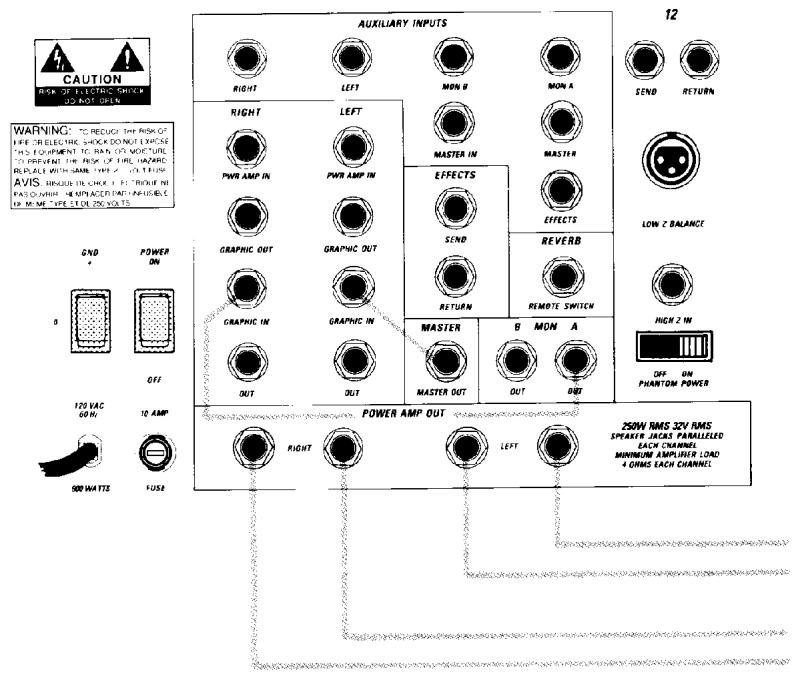
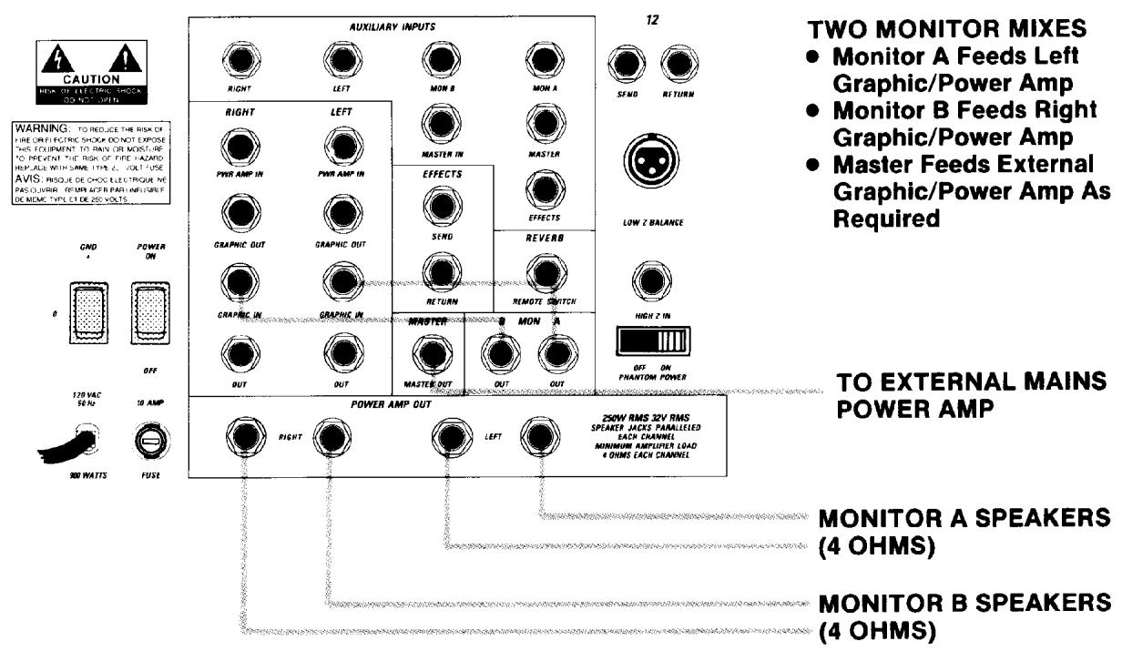
MONO SYSTEM
- Left Graphic/Power Amp For Mains
● Right Graphic/Power Amp For Monitor (A).
MAIN SPEAKERS (4 OHMS)
MONITOR SPEAKERS (4 OHMS)
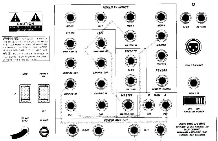
MONO SYSTEM
- Left Sub Equalized (Left Graphic)
• Right Sub Not Equalized
● Master Feeding Left Power Amp (Mains) - Monitor (A) Equalized - Feeding Graphic/Power Amp (Right)
MAIN SPEAKERS (4 OHMS)
MONITOR SPEAKERS (4 OHMS)
AMA 1200 SPECIFICATIONS
All specifications are typical unless otherwise noted.
0 dBV = 1 Volt
0 dBV .778 Volt
All specifications are referenced to nominal output level (0 dBV) unless otherwise noted.
All measurements are wide band 20 Hz unless otherwise stated.
CHANNEL
Equivalent Input Noise:
-112 dBV (150 ohm, 25 degrees C., 30 dB gain)
-113 dBV (150 ohm, 25 degrees C., 40 dB gain)
(Mic Input to Channel Pre Send)
Frequency Response:
±dB 20-20,000 Hz all EQ Flat
Distortion:
Less than .05% @ 0 dB output 40 dB gain
Typical .01% @ 0 dB output 30 dB gain
(Mic input to L or R outputs, EQ flat, sliders at 0)
Input Impedance:
Low Z Bal = 3K ohms
High Z In = 100K ohms
Return = 20K ohms
Output Impedance:
Send = 100 ohms
High EQ:
±15 dB @ 10 kHz minimum
Center detent flat ± 2 dB
Mid EQ:
±12 dB @ 650 Hz minimum
Center detent flat ± 2 dB
Low EQ:
±15 dB @ 50 Hz minimum
Center detent flat ± 2 dB
Maximum Preamp Gain: (Low Z Input to Channel
Send)
40 dB
Maximum Preamp Gain: (High Z Input to Channel
Send)
30 dB
Minimum Preamp Gain:
-40 dB
Maximum Channel Gain:
(Pan at L or R, slide @ max, EQ flat)
56 dB
Maximum Input Level:
Low Z Bal = +8.6 dBV (2.7 V RMS)
High Z In = +18 dBV (8 V RMS)
Return = +18 dBV (8 V RMS)
Maximum Output Level:
Send = +18 dBV (8 V RMS)
Nominal Input Level:
Low Z Bal = -25 dBm (45 mV, -27 dBV)
High Z In = -18 dB (100 mV, -20 dBV)
Return = 0 dBV (1.0 V RMS)
Headroom:
Nominal = 18 dB
Red LED = 3 dB
Pan Characteristics:
2 dB down @ mid position
LED Level:
+15 dBV (15.6 dBV)
MASTER
LED Meter Calibration:
0 = 0 dBV (1.0 V RMS)
Nominal Output Level:
Master: = +0 dBV (1.0 V RMS)
L & R: = +0 dBV (1.0 V RMS)
Monitor A & B: = +0 dBV (1.0 V RMS)
Effects: High = 0 dBV (1.0 V RMS)
Low = -12 dBV (.25 V RMS)
Nominal Headroom:
Master: = 18 dB
L & R: = 18 dB
Monitor A & B: = 18 dB
Effects A & B: = 18 dB
Maximum Output Level:
Master: = +18 dBV (8 V RMS, +20 dBV)
L & R: = +18 dBV (8 V RMS, +20 dBV)
Monitor A & B: = +18 dBV (8 V RMS, +20 dBV)
Effects A: High = 18 dBV (9.0 V RMS, +20 dBV)
Low = 6 dBV (2.0 V RMS, +8 dBV)
Output Impedance:
Master: = 100 ohms
L & R: = 100 ohms
Monitor A & B: = 100 ohms
Effects A: High = 1000 ohms
Low = 250 ohms
Output Noise:
Residual: -99 dBV
(L & R sliders down)
Bus -87 dBV
(All Channel sliders down, effects returns down, all Pan at middle)
Nominal: -70 dBV
(All channels at 30 dB gain, 150 ohm input, EQ flat,
Pan middle, sliders at 0, all assigns at L & R, effects
returns down)
Effects Return Input Impedance:
100K ohms
Effects Return Gain:
16 dB Max
Aux Return Gain:
(Master, L, R, Mon A & B, Efx A & B)
0 dB
Headphone:
Stereo 8 ohm to 200 ohm nominal
Tip = Left, Ring = Right, Sleeve = Ground
500 mW total power
Less than 1% distortion
GRAPHIC EQUALIZERS
(All sliders flat, 1.0 V RMS unless noted)
Filter Bandwidth:
octave
Filter Frequencies:
63, 125, 250, 300, 1K, 2K, 4K, 8K, 16K, Hz (ISO Stds.)
Filter Q:
1.57
Maximum Boost & Cut:
±12 dB
Distortion: (THD)
.05% maximum
Frequency Response:
5 Hz to 40 kHz ±1 dB
Input Level:
Nom = 0 dBV (1.0 V RMS)
Max = 19 dBV (9 V RMS)
Output Level:
Nom = 0 dBV (1.0 V RMS)
Max = 19 dBV (9 V RMS)
Input Impedance:
20K ohms
Output Impedance:
100 ohms
Phantom Power:
15V DC - switchable
AMA 1200
POWER AMPLIFIER SECTION:
Input Sensitivity:
1.0 volts (for rated output)
Output Power:
(@120V AC, 1 kHz)
Single Amplifier: 250 watts @ 4 ohms
150 watts @ 8 ohms
Both Amplifiers: 250 watts @ 4 ohms
150 watts @ 8 ohms
2 ohm operation not recommended.
Total Harmonic Distortion:
.05%
Compression:
DDT™
Cooling:
Fan augmented convection cooling.
Note: Fan does not run unless needed.
Protection:
Short and open circuit protection.
High temperature protection.
Primary fuses.
Frequency Response:
-0, -1 dB 10 Hz to 40 kHz, at 150 watts into 4 ohms
Slew Rate:
40V/microsecond into 4 ohms
Damping Factor:
Greater than 200 at 1 kHz, 4 ohms
Total Harmonic Distortion:
Less than 0.3% 100 mW to 150 W RMS, 10 Hz to
20 kHz, 4 ohms, typically below 0.1%
DDT™ Dynamic Range:
Greater than 20 dB
DDT™ Maximum THD:
Below 0.5% for 6 dB overload; below 0.8% for 14
dB overload
Hum & Noise:
100 dB below 150 W (20 Hz - 20 kHz)
Power Requirements:
120 V AC. 800 watts max
PREAMP SECTION:
Equivalent input noise:
-113 dBV (150 ohms, 40 dB gain, 25 Deg. C)
Maximum output level:
+18 dBV (8 V RMS) (Main, Monitor & Effects)
Frequency Response:
+0, -3 dB, 20 Hz to 20 kHz (all EQ flat)
THD:
Below 0.05% @ 0 dBV, 20 Hz to 20 kHz
(any in/out)
Channel EQ:
±15 dB @ 50 Hz, 600 Hz & 10 kHz
Master Graphic EQ's:
±12 dB @ 63 Hz, 125 Hz, 250 Hz, 500 Hz, 1
kHz, 2 kHz, 4 kHz, 8 kHz, & 16 kHz
Hum & Noise
-70 dBV (low Z inputs, all channel on)
LIMITED WARRANTY
Peavey Electronics Corporation warrants to the original purchaser of this new Architectural Acoustics product that it is free from defects in material and workmanship. If within one (1) year from date of purchase a properly installed product proves to be defective and Peavey is notified, Peavey will repair or replace it at no charge. (Note: Batteries and patch cords not covered.) "Original purchaser" means the customer for whom the product is originally installed.
Damage resulting from improper installation, interconnection of a unit or system of another manufacturer, accident or unreasonable use, neglect or any other cause not arising from defects in material and workmanship is not covered by this warranty. The warranty is valid only as to products purchased and installed in the United States.
THIS LIMITED WARRANTY IS IN LIEU OF ANY AND ALL WARRANTIES, EXPRESSED OR IMPLIED, INCLUDING THE IMPLIED WARRANTIES OF MERCHANTABILITY AND FITNESS FOR A PARTICULAR USE. UNDER NO CIRCUMSTANCES WILL PEAVEY BE LIABLE FOR ANY LOST PROFITS, LOST SAVINGS, INCIDENTAL DAMAGES OR CONSEQUENTIAL DAMAGES ARISING OUT OF THE USE OR INABILITY TO USE THE PRODUCT, EVEN IF PEAVEY HAS BEEN ADVISED OF THE POSSIBILITY OF SUCH DAMAGE. THIS LIMITED WARRANTY IS THE ONLY EXPRESSED WARRANTY ON THIS PRODUCT, AND NO OTHER STATEMENT, REPRESENTATION, WARRANTY, OR AGREEMENT BY ANY PERSON SHALL BE VALID OR BINDING UPON PEAVEY.
Peavey's liability to the original purchaser for damages for any cause whatsoever and regardless of the form of action, is limited to the actual damages up to the greater of Five Hundred Dollars (\$500) or an amount equal to the purchase price of the product that caused the damage or that is the subject of or is directly related to the cause of action. This limitation of liability will not apply to claims for personal injury or damage to real property or tangible personal property allegedly caused by Peavey's negligence. For information on service under this warranty, call a Peavey customer service representative at (601) 483-5376.
DANGER
EXPOSURE TO EXTREMELY HIGH NOISE LEVELS MAY CAUSE A PERMANENT HEARING LOSS INDIVIDALS VARY CONSIDERABLY IN SUSCEPTIBILITY TO NOISE INDUCED HEARING LCSS. BUT NEARLY EVERYONE WILL LOSE SOME HEARING IF EXPOSED TO SUFFICIENTLY IN'ENSE NOISE FOR A SUFFICIENT TIME. THE U.S. GOVERNMENT'S OCCUPATIONAL SAFETY AND HEALTH ADMINISTRATION (OSHA) HAS SPECIFIED THE FOLLOWING PERMISSIBLE NOISE LEVEL EXPOSURES
DURATION PER DAY IN HOURS
SOUND LEVEL dBA, SLOW RESPONSE
| 8 | 90 |
| 6 | 92 |
| 4 | 95 |
| 3 | 97 |
| 2 | 100 |
| 1 | 102 |
| 1 | 105 |
| . | 110 |
| n hours | 1.5 |
- or less
ACCORDING TO CHINA ANY EXPOSURE IN EXCESS OF THE ABOVE PERMISSIBLE LIMITS COULD RESULT IN SOME IFARING LOSS: EAR PLUGS OR PROTECTORS IN THE EAR CANALS OR OVER THE EARS MUST BE WORN WHEN OPERATING THIS AMPLIFICATION SYSTEM IN ORDER TO PREVENT A PERMANENT HEARING LOSS IF EXPOSURE IS IN EXCESS OF THE LIMITS AS SET FORTH ABOVE. O INSURG ARE AGAINST POTENTIALLY DANGEROUS EXPOSURE TO HIGH SOUND PRESSURE LEVELS. IT'S INCOMMENDED THAT ALL PHEISENLESS ITEMS TO EQUIPMENT CAPABLE FOR PRODUCING HIGH SOUND PRESSURE LEVELS, SUCH ADAMINICATION SYSTEM BE PROTECTED BY HEARING PROTECTORS WHILE THIS/INIT IS IN OPERATION.
THIS WIREWAY, ASOLE/EFFECTS DEVICE/PREARP HAS BEEN DESIGNED AND CONSTRUCTED TO PROVIDE ADEQUATE SIGNAL VOLTAGE FOR PLAYING MODERN MUSIC IMPROPER USE OF THE GOURY, NEUTRALIZER CONTROLS AND/OR PROCESSED EXTERNAL SUSTESE'S WAY. CREATS CLIPPING (SQUARE WAVES) AND POSSIBLY DORGE SUBSEQUENT DAMAGE TO THE LOUISPEAKER SYSTEMS EXTENDED OPERATION OF THE GAIN EQUILIZATION CONTROLS IN THEIR MAXIMUM POSITION IS THEREFORE NOT RECOMMENDED PLEASE BE AWARE THAT MAXIMUM POWER CAN BE OPTAINED WITH VERY LOW SET INCE OF THE GAIN/QUALIZATION CONTROLS IF THE INFANT SIGNAL IS VERY STRONG.
IT IS COMMON PRACTICE AMONG USERS OF SOUND REINFORCEMENT EQUIPMENT TO IDENTIFY THE INDIVIDUAL CHANNELS WITH A STRIP OF TAPE PLACED ABOVE OR BELOW THE ROW OF VOLUME FADERS. ANY TYPES OR BRANDS OF TAPE HAVE A VERY STRONG ANGELIVE WHICH CAN INHIBIT THE PAINT ON THE FACERATE AND ACTUALLY REMOVE! THE PAINT WHEN THE TAPE IS NEEDED IT STRONGLY IN COMVEND TO SCOTCH TAPE NOT BE USED ON PAINTED SURFACE FOR ANY OTHER TAPE THAT IS NOT SPECIFIC. THIS PROCESSED FOR SUCH APPLICATIONS METER OR LIGHT SCOTCH TAPE FOR THESE APPLICATIONS
- Read all safety and operating instructions before using this product.
- All safety and operating instructions should be retained for future reference
3 Obey all cautions in the operating instructions and on the back of the unit. - All operating instructions should be followed
- This product should not be used near water, i.e. a bathtub, sink, swimming pool, wet basement, etc
- This product should be located so that its position does not interfere with its proper ventilation. It should not be placed flat against a wall or placed in a built-in enclosure that will impede the flow of cooling air.
-
This product should not be placed near a source of heat such as a stove, radiator or another heat producing amplifier.
-
Connect only to a power supply of the type marked on the unit adjacent to the power supply cord.
- Never break off the ground pin on the power supply cord For more information on grounding write for our free booklet "Shock Hazard and Grounding"
-
Power supply cords should always be handled carefully. Never walk or place equipment on power supply cords. Periodically check cords for cuts or signs of stress, especially at the plug and the point where the cord exits the unit.
11 The power supply cord should be unplugged when the unit is to be unused for long periods of time.
12 If this product is to be mounted in an equipment rack, rear support should be provided -
Metal paste can be cleaned with a damp rag. The vinyl covering used on some units can be cleaned with a damp rag or an ammonia based household cleaner if necessary.
- Care should be taken so that objects do not fall and liquids are not spilled into the unit through the ventilation holes or any other openings.
- This unit should be checked by a qualified service technician if
A. The power supply cord or plug has been damaged
B. Anything has fallen or been spilled into the unit.
C. The unit does not operate correctly
D. The unit has been dropped or the enclosure damaged - The user should not to attempt to service this equipment. All service work should be done by a qualified service technician.
PEAVEY®
ARCHITECTURAL ACOUSTICS®
Features and specifications subject to change without notice.
A Division of Peavey Electronics Corporation
711 A Street, P. O. Box 2898, Meridian, MS 39302-2898 / (601) 483-5376 / Telex 504115 / Fax (601) 484-4278

- OPERATING INSTRUCTIONS
- GAIN (1)
- MONITOR (A) SEND (2)
- MONITOR (B) SEND (3)
- HIGH (4)
- MID (5)
- LOW (6)
- OPERATION NOTE
- EFFECTS SEND (7)
- PAN (8)
- PFL (9)
- LIMIT LED (10)
- CHANNEL LEVEL SLIDER (11)
- LED ARRAYS (12)
- LEFT/RIGHT SUBS (13)
- EFFECTS TO MONITOR A (14)
- EFFECTS RETURN (15)
- EFFECTS PAN (16)
- MONITOR (A) MASTER (17)
- REVERB TO MONITOR A (18)
- REVERB RETURN (19)
- REVERB PAN (20)
- MONITOR (B) MASTER (21)
- MASTER (22)
- REVERB TO MONITOR B (23)
- EFFECTS MASTER (24)
- PFL LEVEL (25)
- HEADPHONE LEVEL (26)
- HEADPHONE JACK (27)
- GROUND SWITCH (28)
- POWER SWITCH (29)
- LINE CORD (120V PRODUCTS ONLY) (30)
- FUSE (31)
- AUXILIARY INPUTS (32)
- MASTER INPUT (33)
- POWER AMP INPUT L/R (34)
- GRAPHIC R OUT (35)
- GRAPHIC L OUT (36)
- GRAPHIC INPUT L (37)
- GRAPHIC INPUT R (38)
- LEFT OUT/RIGHT OUT (39)
- SPEAKER OUTPUT JACKS (40)
- EFFECTS OUT (41)
- EFFECTS RETURN (42)
- MASTER OUT (43)
- FOOTSWITCH (44)
- MONITOR OUT (45)
- SEND AND RETURN JACKS (46)
- LOW Z IN (47)
- HIGH Z IN (48)
- PHANTON POWER ON/OFF (49)
- 9-BAND GRAPHIC EQ
- MONO SYSTEM
- AMA 1200 SPECIFICATIONS
- CHANNEL
- MASTER
- GRAPHIC EQUALIZERS
- AMA 1200
- POWER AMPLIFIER SECTION:
- Input Sensitivity:
- Output Power:
- Total Harmonic Distortion:
- Compression:
- Cooling:
- Protection:
- Frequency Response:
- Slew Rate:
- Damping Factor:
- DDT™ Dynamic Range:
- DDT™ Maximum THD:
- Hum & Noise:
- Power Requirements:
- PREAMP SECTION:
- Equivalent input noise:
- Maximum output level:
- THD:
- Channel EQ:
- Master Graphic EQ's:
- Hum & Noise
- LIMITED WARRANTY
- DANGER
- - or less
- PEAVEY®
- ARCHITECTURAL ACOUSTICS®
Marque : PEAVEY
Modèle : AMA 1200
Catégorie : Amplificateur