
ER5018 - Appareil de mesure de la pression artérielle OMRON - Notice d'utilisation et mode d'emploi gratuit
Retrouvez gratuitement la notice de l'appareil ER5018 OMRON au format PDF.


| Type de produit | Interrupteur d'arrêt d'urgence à tirette |
| Marque | OMRON |
| Modèle | ER5018 |
| Dimensions (montage) | Largeur de montage : 40 mm |
| Poids | 675 g |
| Matériau du boîtier | Alliage d'aluminium moulé |
| Matériau de l'écrou à œil | Acier inoxydable |
| Couleur | Jaune |
| Indice de protection | IP67 (NEMA 6) |
| Température de fonctionnement | -25 à 80 °C |
| Capacité de commutation (AC) | 120 V-6 A, 240 V-3 A, inductif |
| Capacité de commutation (DC) | 24 V-2,5 A, inductif |
| Courant minimum | 5 V, 5 mA DC |
| Configuration des contacts | 2 NF + 1 NO ou 3 NF |
| Portée maximale du câble | 40 m |
| Force d'actionnement | < 125 N |
| Force de tension en position de marche | 130 N typique |
| Durée de vie mécanique | 1 000 000 actions minimum |
| Durée de vie électrique | 1 000 000 actions minimum |
| Entrées de câble | 3 x M20 |
| Nettoyage | Lavage à l'eau |
| Accessoires inclus | Bouton de réinitialisation bleu ; option bouton d'arrêt d'urgence rouge |
| Pièces détachées disponibles | Kits de câble, poulies, ressorts, etc. |
| Réparabilité | Ne pas réparer, remplacer le cas échéant |
FOIRE AUX QUESTIONS - ER5018 OMRON
Questions des utilisateurs sur ER5018 OMRON
0 question sur cet appareil. Repondez a celles que vous connaissez ou posez la votre.
Poser une nouvelle question sur cet appareil
Téléchargez la notice de votre Appareil de mesure de la pression artérielle au format PDF gratuitement ! Retrouvez votre notice ER5018 - OMRON et reprennez votre appareil électronique en main. Sur cette page sont publiés tous les documents nécessaires à l'utilisation de votre appareil ER5018 de la marque OMRON.
MODE D'EMPLOI ER5018 OMRON
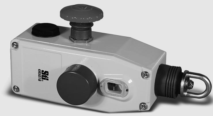
Compact Rope Pull Emergency Stop Switch
ER5018
- Compact size allows this switch to be used on smaller machines with a mounting width of 40mm and covering rope spans up to 40m
- Tension indicator—the tension indicator makes the system easy to set up and to maintain the proper rope tension
- Contact arrangements of 2 ~N / C + 1 ~N / O or 3 ~N / C
- IP67 (NEMA 6) enclosure enables the ER5018 switch to withstand water washdown cleaning
- Heavy-duty housing—the die-cast housing and stainless steel eye nut makes the ER5018 suitable for demanding industrial applications
- Integral E-Stop—the optional E-stop provides emergency stopping at the extreme end of the installation
- Reset button—the blue reset button must be pushed in order to return to "machine run" condition following switch actuation by a pulled or slacked rope
- Long life—the ER5018 switch is designed for a minimum of one million actuations
- Vibration tolerant—the snap-acting switch contacts protect against nuisance tripping due to vibration
C∈cULUS LISTED
Operation
Blue Reset Button

A blue reset button is provided to easily return the unit back to its machine-run position after actuation.
Emergency Push Button
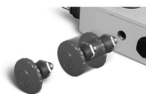
The emergency push button may be installed or repositioned in the field. The ER5018 has two possible mounting positions for the emergency stop button.
Installation Hardware Available
RK Rope Tension Kit

The RK Rope Tension Kit comes with all of the required hardware for most installations. A spring is required as shown in the installation example below.
Installation Hardware
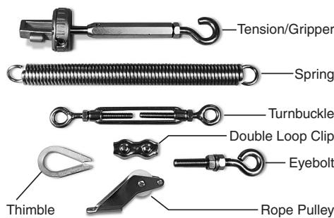
Individual hardware items may be purchased for specific installation requirements.
| 0 mm | 3.5 mm | 14.5 mm | 17.0 mm |
| 2NC + 1NO Versions | Rope Slack | Tension Range | Rope Pulled |
| 11/12 | |||
| 21/22 | |||
| 33/34 | |||
| 3NC Versions | Rope Slack | Tension Range | Rope Pulled |
| 11/12 | |||
| 21/22 | |||
| 31/32 | |||
Mounting Specification
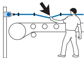

Note: Some installations may require a ER5018 on each end.
Applications
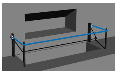
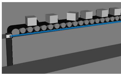
Typical applications are on conveyor systems and across rotating machinery, and around hazardous areas.
Ordering information
Compact Rope Pull Emergency Stop Switch
| E-Stop | Contacts | Wiring Entry | Model |
| Not included | 2 N/C + 1 N/O | 3 x M20 | ER5018-021M |
| Not included | 3 N/C | 3 x M20 | ER5018-030M |
| Included | 2 N/C + 1 N/O | 3 x M20 | ER5018-021ME |
| Included | 3 N/C | 3 x M20 | ER5018-030ME |
Accessories
| Item | Model |
| Replacement Lid | SM06-SL400 |
| Rope Kit, 5 m, Stainless Steel | RK5 |
| Rope Kit, 10 m, Stainless Steel | RK10 |
| Rope Kit, 20 m, Stainless Steel | RK20 |
| Rope Kit, 50 m, Stainless Steel | RK50 |
| Rope Only, 5 m | R5M |
| Rope Only, 10 m | R10M |
| Rope Only, 20 m | R20M |
| Rope Only, 50 m | R50M |
| Rope Only, 100 m | R100M |
| Rope Only, 126 m | R126M |
| Tensioner Gripper, Stainless Steel | SM06-TG00 |
| Eye Bolt Stainless Steel, 8 per pack | SM06-EB10 |
| Double Loop Clip, Stainless Steel, 4 per pack | SM06-DL20 |
| Thimble Stainless Steel, 4 per pack | SM06-THSS |
| Turnbuckle, Stainless Steel | SM06-TB30 |
| Spring, Stainless Steel | SM06-SP50 |
| Rope Pulley, Stainless Steel | SM06-RPSS |
| E-Stop Mechanism | SM06-ES60 |
Specifications
| Electrical | Contact Configurations | 2 N/C + 1 N/O, 3 N/C |
| Safety Contacts | 2 N/C, 3 N/C | |
| Switching Ability | AC: 120 V-6 A, 240 V-3 A, Inductive DC: 24 V-2.5 A, Inductive | |
| Auxiliary Contacts | 1 N/O | |
| Max Switching Current/Volt/Amp | 240 V/720 VA | |
| Minimum Current | 5 V, 5 mA DC | |
| Electrical Life | 1,000,000 minimum | |
| Mechanical | Mounting | Any position |
| Mounting Hardware | 2 x M5 screws | |
| Actuator Travel for Positive Opening | See diagrams on previous page | |
| Max Rope Span | 40 m | |
| Operation Force | < 125 N | |
| Tensioning Force to Run Position | 130 N typical | |
| Case Material | Die-cast aluminum alloy | |
| Eye Nut Material | Stainless steel | |
| Wiring Entry | 3 x M20 | |
| Weight | 675 g | |
| Color | Yellow | |
| Mechanical Life | 1,000,000 minimum | |
| Environmental | Protection | IP67 (NEMA 6) |
| Operating Temperature | -25 to 80°C | |
| Cleaning | Water washdown | |
| Compliance | Standards | IEC947-5-1, IEC947-5-5, EN418, UL508, BS5304 |
| Approvals/Listings | CE marked for all applicable directives, UL and C-UL |
Note: The safety contacts of the Omron STI switches are described as normally closed (N/C)—i.e., with the rope properly tensioned and the machine able to be started.
Dimensions
Operating instructions
Installation must be in accordance with the following steps and stated specifications and should be carried out by suitably competent personnel. Adherence to the recommended maintenance instructions forms part of the warranty.

WARNING
Do not defeat, tamper, remove or bypass this unit. Severe injury to personnel could result.
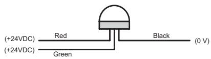
Optional 24 VDC Indicator Beacon
When +24VDC is applied to the red wire, the beacon will illuminate red and flash.
When +24 VDC is applied to the green wire, the beacon will illuminate green.
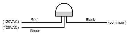
Optional 120 VAC Indicator Beacon
When +120VAC is applied to the red wire, the beacon will illuminate red and flash.
When +120 VAC is applied to the green wire, the beacon will illuminate green.
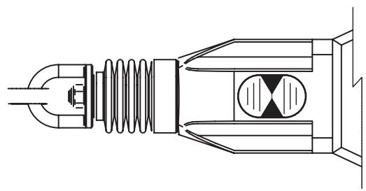
Tension Indicator
Indicator shown with steel rope properly adjusted.
WARNING
- Installation of all Safety Rope Switch systems must be in accordance with a risk assessment for the individual application. Installation must only be carried out by competent personnel and in accordance with these instructions.
- Rope support eyebolts must be fitted at 2.5m min. to 3m max. intervals along all rope lengths between switches. The rope must be supported no more than 500mm from the switch eyebolt or Safety Spring (if used). It is important that this first 500mm is not used as part of the active protection coverage.
- M5 mounting bolts must be used to fix the switches. Tightening torque for mounting bolts to ensure reliable fixing is 4Nm . Tightening torque for the lid screws, conduit entry plugs and cable glands must be 1.5Nm to ensure IP seal. Only use correct sizing glands for conduit entry and cable outside diameter.
- Tensioning of rope is achieved by use of tensioner / gripper assemblies. Upon installation, tension to mid-position as indicated by the red arrows in the viewing window of each switch. Check operation for all switches and the control circuits by pulsing the rope at various locations along the active protection area and resetting each switch by depressing the Blue Reset button. Ensure each time that the switches latch off and require manual resetting by depressing the Blue Reset button. Increase the system tension further, if required, depending upon the checks along the active length of coverage. If fitted with a Mushroom type E-Stop button (Red) then test and reset each switch to ensure function of control circuits. Typical operational conditions for successful operation of system is less than 75 N. pulling force and less than 150mm deflection of rope between eyebolt supports. If the optional LED is fitted but is not used, ensure that the conductors remain coiled and tied to the tie hole in the LED flange.
- Every week: Check correct operation of system at locations along all coverage length. Check for nominal tension setting, re-tension rope if necessary. Every 6 months: Isolate power and remove cover. Check screw terminal tightness and check for signs of moisture ingress. Never attempt to repair any switch.
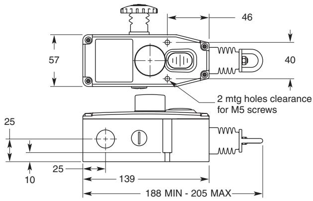
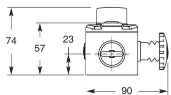
ALL DIMENSIONS SHOWN ARE IN MILLIMETERS.
To convert millimeters into inches, multiply by 0.03937. To convert grams into ounces, multiply by 0.03527.
- Compact Rope Pull Emergency Stop Switch
- ER5018
- Operation
- Blue Reset Button
- Emergency Push Button
- Installation Hardware Available
- RK Rope Tension Kit
- Installation Hardware
- Mounting Specification
- Applications
- Ordering information
- Operating instructions
- WARNING
- Optional 24 VDC Indicator Beacon
- Optional 120 VAC Indicator Beacon
- Tension Indicator
Marque : OMRON
Modèle : ER5018
Catégorie : Appareil de mesure de la pression artérielle