
E3X-DA-S - Capteur de détection optique OMRON - Notice d'utilisation et mode d'emploi gratuit
Retrouvez gratuitement la notice de l'appareil E3X-DA-S OMRON au format PDF.


| Type de produit | Capteur de détection optique (amplificateur à fibre optique) |
| Marque | OMRON |
| Modèle | Série E3X-DA-S |
| Tension d'alimentation | DC 12 à 24 V ±10%, ondulation 10% max. |
| Consommation électrique | 960 mW max. (40 mA max. à 24 V) |
| Sortie de commande | Collecteur ouvert NPN/PNP (selon modèle), 26,4 V max., 50 mA max., tension résiduelle 1 V max. |
| Temps de réponse | 1 ms |
| Protection contre les interférences mutuelles | Jusqu'à 10 amplificateurs (synchronisation par communication optique) |
| Affichage | 2 afficheurs numériques : principal rouge (niveau de lumière 0-4000), secondaire vert (seuil) |
| Modes de détection | LON (lumière active) / DON (obscurité active) |
| Réglage du seuil | Manuel par touches ou par enseignement (avec/sans pièce, automatique) |
| Méthode de montage | Rail DIN |
| Type de fibre | Fibre optique en résine méthacrylique |
| Précautions d'utilisation | Ne pas utiliser en atmosphère explosive ou avec solvants organiques |
| Nettoyage | Ne pas utiliser de diluant, benzène, acétone ou pétrole |
| Câble d'alimentation | Longueur max. d'extension 100 m, section min. 0,3 mm² |
| Temps de stabilisation au démarrage | 200 ms |
| Console de paramétrage | E3X-MC11-S (obligatoire) |
| Indication d'erreur | Affichage "E" clignotant en cas d'erreur d'enseignement ou mémoire |
FOIRE AUX QUESTIONS - E3X-DA-S OMRON
Questions des utilisateurs sur E3X-DA-S OMRON
0 question sur cet appareil. Repondez a celles que vous connaissez ou posez la votre.
Poser une nouvelle question sur cet appareil
Téléchargez la notice de votre Capteur de détection optique au format PDF gratuitement ! Retrouvez votre notice E3X-DA-S - OMRON et reprennez votre appareil électronique en main. Sur cette page sont publiés tous les documents nécessaires à l'utilisation de votre appareil E3X-DA-S de la marque OMRON.
MODE D'EMPLOI E3X-DA-S OMRON
Digital Fiber Sensors
E3X-DA-S Series
Single functional type(E3X-DA□SE-S)
Instruction Sheet
Thank you for selecting an OMRON product. This sheet primarily describes precautions required in installing and operating the product.
- The specialist who has the knowledge of electricity must treat.
- Please often read this manual, and use it correctly after it understands enough.
- Please keep this manual importantly to refer at any time.
© OMRON Corporation 2004 All Rights Reserved.
1636508-9A
Precautions for Safe Use
Please observe the following precautions for safe use of the product.
1) Do not use the Amplifier Unit in environments subject to flammable or explosive gases.
2) Do not use the Amplifier Unit in environments subject to exposure to water, oil, chemicals, etc.
3) Do not attempt to disassemble, repair, or modify the Amplifier Unit in any way.
4) Do not apply voltages or currents that exceed the rated ranges.
5) Wire the Amplifier Unit correctly, e.g., do not reverse the polarity of the power supply.
6) Connect the load correctly.
7) Do not short both ends of the load.
8) Do not use the Amplifier Unit if the case is damaged.
9) When disposing of the Amplifier Unit,treat it as industrial waste.
Precautions for Correct Use
Please observe the following precautions to prevent failure to operate, malfunction, or undesirable effects on product performance.
1) The optical fibers are made out of methacrylic resin. Do not use them in atmospheres where organic solvents are present.
2) Wire the Amplifier Unit separately from power supply or high-voltage lines. If the Amplifier Unit wiring is wired together with or placed in the same duct as high-power lines, inductive noise may cause op-erating errors or damage the Amplifier Unit.
3) Do not extend the cable to more than 100m , and use a wire size of 0.3mm^2 or larger for the extension cable.
4) The Amplifier Unit is ready to operate 200 ms after the power supply is turned ON. If the Amplifier Unit and load are connected to power supplies separately, turn ON the power supply to the Amplifier Unit first.
5) Always keep the protective cover in place when using the Amplifier Unit.
6) Connector Short-circuit Protection (for Amplifier Units with
Connectors)To prevent electric shock or short-circuits, attach the connectors with a 50% ON switch.
the protector seal provided with E3X-CN-series Connectors to the sides of power supply connectors that are not being used.
Always turn OFF the power supply before connecting, separate
Always turn OFF the power supply before connecting, separating, or adding Amplifier Units.
Using a Mobile Console
Use the E3X-MC11-S Mobile Console for the E3X-DA-S-series Amplifier Units. Other Mobile Con-soles, such as the E3X-MC11, cannot be used.
Optical communications are not possible with an E3X-DA-N Amplifier Unit.
10) Depending on the application environment, time may be required for the incident light level to sta-bi-ize after the power supply is turned ON.
11) Please do not use thinner, benzine, acetone, and lamp oil for cleaning.
12) The optical fibers are made out of methacrylic resin. Do not use them in atmospheres where organic solvents are present.
13) Do not pull or apply excessive pressure or force (exceeding 9.8 N·m) on the Fiber Unit when it is mounted to the Amplifier Unit.
14) It cannot be used, when you have With and Without a Workpiece, it becomes 4000 or more digital values by each. In this case, please examine the type which re-sets up fiber unit or can perform power adjustment so that light level may become small. (This model is a single functional type and power adjustment cannot be performed.)
15) If the data is not written to the EEPROM correctly due to a power failure or staticelectric noise, as
Confirming the Package Contents
Amplifier Unit : 1 · Instruction Sheet (this sheet) : 1
Ratings and Specifications
| Connection method | Prewired | Separate connector * | |
| Model | NPN | E3X-DA11SE-S | E3X-DA6SE-S |
| PNP | E3X-DA41SE-S | E3X-DA8SE-S | |
| Supply voltage | DC12~24V±10% ripple(p-p)10% max. | ||
| Power consumption | 960 mW max. (40 mA max. at 24 V) | ||
| Control output | Open collector (26.4 VDC max.); load current: 50 mA max.; residual voltage: 1 V max. | ||
| Response time | 1ms | ||
| Mutual interference prevention | Possible for up to 10 Units (optical communications sync method) | ||
: Either the E3X-CN11 Master Connector (3-conductor) or the E3X-CN12 Slave Connector (1-conductor) can be used.
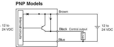
I/O Circuits
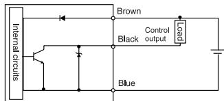
NPN Models
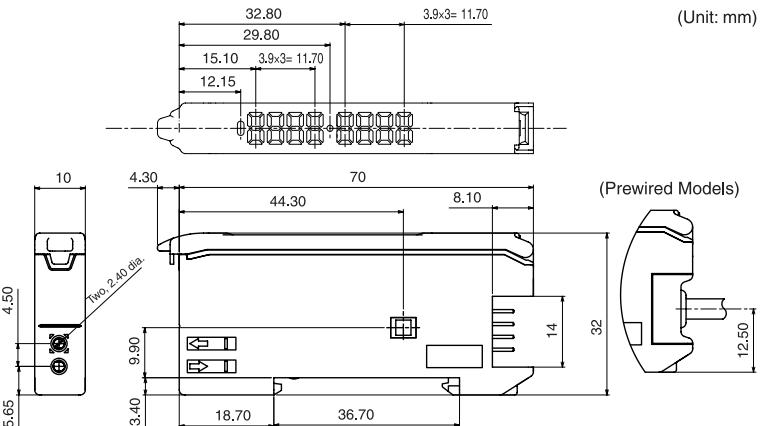
Dimensions
The installation method
Mounting Units
Catch the hook on the Fiber Unit connector end of the Unit on the DIN Track and then press down on the other end of the Unit until it locks into place.
Always attach the Fiber Unit connector end first. If the incorrect end is attached first, the mounting strength will be reduced.
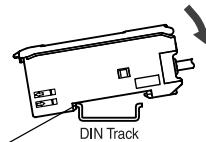
Hook on the Fiber Unit connector end
Removing Units
Press the Unit in the direction indicated by "1" and then lift up on the Fiber Unit connector end of the Unit in the direction indicated by "2."
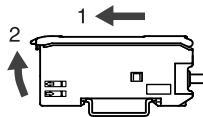
DIN Track
Display/Operation
Main digital display(Red)
Incident Light level is displayed with
digital value(0~max4000).
Sub digital display(Green)
Threshold value is displayed.
Thereshold adjustment key
Used to adjust threshold value.

Display light of operation
Lit when the output ON.
Keylock switch
Used to lock the key or not.
Operation mode selector
Used to select LON or DON operation.
1. Basic Settings

2. Threshold values Manually setting

3. Treshold values Setting by Teaching
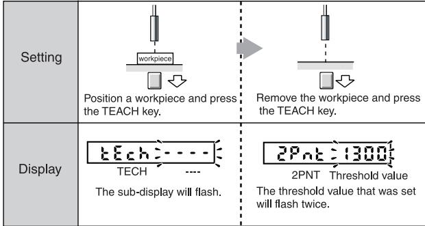
① Teaching With and Without a Workpiece(It sets up at workpiece that doesn't move.)
Teaching can be performed twice, once with and once without a workpiece, and the value between the two measured values is set as the threshold.
② Automatic-teaching(It sets up at move work.)
While continuing pushing a key, the middle of the detected maximum and the minimum value can be set up as a threshold.

Teaching error
After performing teaching, when the following is displayed on a sub digital display, the error has occurred.
E
lashes
twice
e
1
一
二、
1
E
1
Lig
H
Veris
100
large
9.D
Electricity
on m
ay be
e con
rectly
.
C
VER
m = 311 ;
1
1
ble,
adine
bug
the
SHOLD
I val
He is.
set a
1
AX
val
a.e.
ajust
the
1.4
图10
核心
1
一
.
.
LO
.
LO
Liq
imp
level
s too.
sma
II.De
tecti
on m
ayb
e con
ble,
atthc
Bugh
thre
shole
I vall
He is.
Set a
F
ashes
s twice
e
一
Cha
e of li
ght I
level
ssm
all D
etec
tion u
may
npos
sible
, alth
oual
nath
fresh
old i
s set
m w
blue
Adjui
st the
Hea
ad to
incr
ease
etwe
ent
ne two
o inc
iden
t light
t lev
el.
eI.
0
MTT
IDF
R0
00
18
T
THE
FR
E
(AB)
ATC
Se
e al
so E
Proc
uct.
aloe
for
Wu
rran
ty a
Jim
tati
on o
f1jz
Memory error

Err EEP
it
di
tal
sp
m = 311
X.
m = 311 ;
is
spl
m = 311 ;
rec
as
EE
EP.
1
2.
Slide
det
ne /
Amp
ifie
rU
nits
s to
eth
ran
d pi
SS
e A
mpli
ier
Uni
s
1
.
m = 311 ;
CK
m = 311
12 =
一
一
-1
ON
1
and
ed
一
一
一
U
1
1
C
and
Bc
山
+
3
11
54
Vua
11
18C
14
1y
C.
m = 311
S.A.
A
23
99
Reverse the above procedure to disconnect the Fiber Unit.
Initialization has been completed
OOD
In
aliz
tion
nas
eeee
COI
ple
d.
1
.
be above procedure to disconnect the Fiber Unit.
三
信
品
一
1
26
一
1
0
1
1
C
arl-
B
nz
Str
4,
D-7
B:711
54]
Nuf
or
Sus gen
McGe
rm
any
m = 311
a
S.A
23
99
- Digital Fiber Sensors
- E3X-DA-S Series
- Single functional type(E3X-DA□SE-S)
- Instruction Sheet
- Precautions for Safe Use
- Precautions for Correct Use
- Confirming the Package Contents
- Ratings and Specifications
- I/O Circuits
- Dimensions
- The installation method
- Mounting Units
- Removing Units
- Display/Operation
- Basic Settings
- Threshold values Manually setting
- Treshold values Setting by Teaching
- ① Teaching With and Without a Workpiece(It sets up at workpiece that doesn't move.)
- ② Automatic-teaching(It sets up at move work.)
- Teaching error
- Memory error
Marque : OMRON
Modèle : E3X-DA-S
Catégorie : Capteur de détection optique