
D4NL - Capteurs de position OMRON - Notice d'utilisation et mode d'emploi gratuit
Retrouvez gratuitement la notice de l'appareil D4NL OMRON au format PDF.


| Type de produit | Interrupteur de sécurité à verrouillage de porte (Guard Lock Safety-door Switch) |
| Marque | OMRON |
| Modèle | D4NL |
| Catégorie | Capteurs de position |
| Dimensions (approx.) | 30,5 x 28,5 x 95 mm (hors tout) |
| Poids | Environ 370 g (modèle D4NL-IAFA-B) |
| Alimentation de l'électroaimant | 24 VDC, 110 VAC ou 230 VAC selon version |
| Consommation de l'électroaimant | Environ 200 mA (24 VDC), 50 mA (110 VAC), 30 mA (230 VAC) |
| Degré de protection | IP67 (boîtier), IP00 (trou de clé) |
| Force de maintien de la clé | 1 300 N min. |
| Force d'ouverture directe | 60 N min. (selon EN60947-5-1) |
| Course d'ouverture directe | 10 mm min. (selon EN60947-5-1) |
| Endurance mécanique | 1 000 000 opérations min. |
| Endurance électrique | 500 000 opérations min. (charge résistive 3 A à 250 VAC) |
| Température ambiante de fonctionnement | -10°C à 55°C (sans givrage) |
| Humidité ambiante | 95% max. |
| Tension d'isolement assignée | 300 V |
| Résistance d'isolement | 100 MΩ min. (à 500 VDC) |
| Classe de protection | Classe II (double isolation) |
| Matériau de la tête | Plastique ou métal selon version |
| Types de verrouillage | Verrouillage mécanique avec déverrouillage par solénoïde, ou verrouillage par solénoïde avec déverrouillage mécanique |
| Indicateur | LED orange (10 à 115 VAC/VDC) ou lampe néon orange (100-230 VAC) |
| Entrée de conduit | Pg13.5, G1/2 ou M20 selon version |
| Maintenance | Ne pas réparer soi-même ; contacter le fabricant de la machine. |
| Pièces détachées | Clés de commande vendues séparément (modèles D4DS-K1, K2, K3, K5) |
FOIRE AUX QUESTIONS - D4NL OMRON
Questions des utilisateurs sur D4NL OMRON
0 question sur cet appareil. Repondez a celles que vous connaissez ou posez la votre.
Poser une nouvelle question sur cet appareil
Téléchargez la notice de votre Capteurs de position au format PDF gratuitement ! Retrouvez votre notice D4NL - OMRON et reprennez votre appareil électronique en main. Sur cette page sont publiés tous les documents nécessaires à l'utilisation de votre appareil D4NL de la marque OMRON.
MODE D'EMPLOI D4NL OMRON
Guard Lock Safety-door Switch
D4NL
Lead-free,
Environment-friendly Design
- Contains no harmful substances, such as lead or cadmium, reducing the burden on the environment.
- Models with 4-contact and 5-contact built-in switches are available.
Key holding force of 1,300 N min. - Can be used for either standard loads or microloads.
- Lineup includes models with a conduit size of M20.
- IP67 degree of protection.
Operation key compatible to D4DS, D4NS and D4GL.
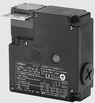
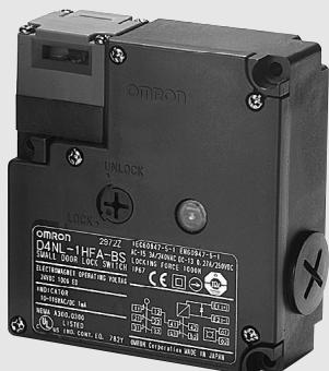


Model Number Structure
Model Number Legend
Switch
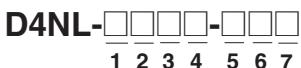
1. Conduit Size
1: Pg13.5
2: G1/2
4: M20
2. Built-in Switch (with Door Open/Closed Detection Switch and Lock Monitor Switch Contacts)
A: 1NC/1NO slow-action contacts plus 1NC/1NO slow-action contacts
B: 1NC/1NO slow-action contacts plus 2NC slow-action contacts
C: 2NC slow-action contacts plus 1NC/1NO slow-action contacts
D: 2NC slow-action contacts plus 2NC slow-action contacts
E: 2NC/1NO slow-action contacts plus 1NC/1NO slow-action contacts
F: 2NC/1NO slow-action contacts plus 2NC slow-action contacts
G: 3NC slow-action contacts plus 1NC/1NO slow-action contacts
H: 3NC slow-action contacts plus 2NC slow-action contacts
3. Head Mounting Direction and Material
F: Four mounting directions possible (Front-side mounting at time of delivery)/plastic
D: Four mounting directions possible (Front-side mounting at time of delivery)/metal
4. Door Lock and Release
A: Mechanical lock/24-VDC solenoid release
B: Mechanical lock/110-VAC solenoid release
C: Mechanical lock/230-VAC solenoid release
G: 24-VDC solenoid lock/mechanical release
H: 110-VAC solenoid lock/mechanical release
J: 230-VAC solenoid lock/mechanical release
5. Indicator
B: 10 to 115 VAC/VDC (orange LED indicator)
E: 100 - 230V VAC (orange neon lamp indicator)
6. Release Key Type
Blank:Standard
4: Special release key
7. Release Key Position
Blank:Bottom
S: Front
Operation Key

1
1. Operation Key Type
1: Horizontal mounting
2: Vertical mounting
3: Adjustable mounting (horizontal)
5: Adjustable mounting (horizontal/vertical)
For 110V and 230V version ask your local OMRON Representative Switches (Operation Keys are sold separately.)
: Models with approved direct opening contacts. Preferred stock item*
List of Models
| Head material | Release key position | Release key type | Solenoid voltage/indicator | Lock and release types | Contact configuration (door open/closed detection switch and lock monitor switch contacts) (slow-action) Approved direct opening NC contact | Conduit opening | Model |
| Plastic | Bottom | Standard | Solenoid: 24 VDC Orange LED: 10 to 115 VAC/VDC | Mechanical lock Solenoid release | 1NC/1NO+1NC/1NO | Pg13.5 | D4NL-1AFA-B* |
| G1/2 | D4NL-2AFA-B | ||||||
| M20 | D4NL-4AFA-B* | ||||||
| 1NC/1NO+2NC | Pg13.5 | D4NL-1BFA-B | |||||
| G1/2 | D4NL-2BFA-B | ||||||
| M20 | D4NL-4BFA-B | ||||||
| 2NC+1NC/1NO | Pg13.5 | D4NL-1CFA-B* | |||||
| G1/2 | D4NL-2CFA-B | ||||||
| M20 | D4NL-4CFA-B* | ||||||
| 2NC+2NC | Pg13.5 | D4NL-1DFA-B | |||||
| G1/2 | D4NL-2DFA-B | ||||||
| M20 | D4NL-4DFA-B | ||||||
| 2NC/1NO+1NC/1NO | Pg13.5 | D4NL-1EFA-B | |||||
| G1/2 | D4NL-2EFA-B | ||||||
| M20 | D4NL-4EFA-B* | ||||||
| 2NC/1NO+2NC | Pg13.5 | D4NL-1FFA-B | |||||
| G1/2 | D4NL-2FFA-B | ||||||
| M20 | D4NL-4FFA-B | ||||||
| 3NC+1NC/1NO | Pg13.5 | D4NL-1GFA-B | |||||
| G1/2 | D4NL-2GFA-B | ||||||
| M20 | D4NL-4GFA-B | ||||||
| 3NC+2NC | Pg13.5 | D4NL-1HFA-B | |||||
| G1/2 | D4NL-2HFA-B | ||||||
| M20 | D4NL-4HFA-B | ||||||
| Solenoid lock Mechanical release | 1NC/1NO+1NC/1NO | Pg13.5 | D4NL-1AFG-B* | ||||
| G1/2 | D4NL-2AFG-B | ||||||
| M20 | D4NL-4AFG-B* | ||||||
| 1NC/1NO+2NC | Pg13.5 | D4NL-1BFG-B | |||||
| G1/2 | D4NL-2BFG-B | ||||||
| M20 | D4NL-4BFG-B | ||||||
| 2NC+1NC/1NO | Pg13.5 | D4NL-1CFG-B* | |||||
| G1/2 | D4NL-2CFG-B | ||||||
| M20 | D4NL-4CFG-B* | ||||||
| 2NC+2NC | Pg13.5 | D4NL-1DFG-B | |||||
| G1/2 | D4NL-2DFG-B | ||||||
| M20 | D4NL-4DFG-B | ||||||
| 2NC/1NO+1NC/1NO | Pg13.5 | D4NL-1EFG-B | |||||
| G1/2 | D4NL-2EFG-B | ||||||
| M20 | D4NL-4EFG-B* | ||||||
| 2NC/1NO+2NC | Pg13.5 | D4NL-1FFG-B | |||||
| G1/2 | D4NL-2FFG-B | ||||||
| M20 | D4NL-4FFG-B | ||||||
| 3NC+1NC/1NO | Pg13.5 | D4NL-1GFG-B | |||||
| G1/2 | D4NL-2GFG-B | ||||||
| M20 | D4NL-4GFG-B | ||||||
| 3NC+2NC | Pg13.5 | D4NL-1HFG-B | |||||
| G1/2 | D4NL-2HFG-B | ||||||
| M20 | D4NL-4HFG-B |
Operation Keys
| Type | Model |
| Horizontal mounting | D4DS-K1 |
| Vertical mounting | D4DS-K2 |
| Adjustable mounting (Horizontal) | D4DS-K3 |
| Adjustable mounting (Horizontal/Vertical) | D4DS-K5 |
Specifications
Standards and EC Directives
Applicable EC Directives and Standards
- Machinery Directive
- Low Voltage Directive
EN1088
EN60204-1
GS-ET-19
Approved Standards
| Agency | Standard | File No. |
| TÜV Product Service | EN60947-5-1 (approved direct opening) | (See note 1.) |
| UL (See note 2.) | UL508, CSA C22.2 No.14 | E76675 |
Note: 1. Consult your OMRON representative for details.
2. Approval for CSA C22.2 No. 14 is authorized by the UL mark.
Approved Standard Ratings
TUV (EN60947-5-1)
| Item | Utilization category | AC-15 | DC-13 |
| Rated operating current (Ie) | 3 A | 0.27 A | |
| Rated operating voltage (Ue) | 240 V | 250 V | |
Note: Use a 10-A fuse type gI or gG that conforms to IEC269 as a short-circuit protection device. This fuse is not built into the Switch.
UL/CSA (UL508, CSA C22.2 No. 14)
A300
| Rated voltage | Carry current | Current | Volt-amperes | ||
| Make | Break | Make | Break | ||
| 120 VAC | 10 A | 60 A | 6 A | 7,200 VA | 720 VA |
| 240 VAC | 30 A | 3 A | |||
Solenoid Coil Characteristics
| Item | 24 VDC | 110 VAC | 230 VAC |
| Rated operating voltage (100% ED) | 24 VDC +10%/ -15% | 110 VAC ±10% | 230 VAC ±10% |
| Current consumption | Approx. 200 mA | Approx. 50 mA | Approx. 30 mA |
| Insulation | Class F (130°C max.) | ||
Indicator Characteristics
| Item | LED |
| Rated voltage | 10 to 115 VAC/VDC |
| Current leakage | Approx. 1 mA |
| Color (LED) | Orange |
Characteristics
| Degree of protection (see note 2) | IP67 (EN60947-5-1)(This applies for the Switch only. The degree of protection for the key hole is IP00.) | ||
| Durability(see note 3) | Mechanical | 1,000,000 operations min. | |
| Electrical | 500,000 operations min. for a resistive load of 3 A at 250 VAC (see note 4) | ||
| Operating speed | 0.05 to 0.5 m/s | ||
| Operating frequency | 30 operations/minute max. | ||
| Rated frequency | 50/60 Hz | ||
| Contact gap | 2 x 2 mm min | ||
| Direct opening force (see note 5) | 60 N min. (EN60947-5-1) | ||
| Direct opening travel (see note 5) | 10 mm min. (EN60947-5-1) | ||
| Holding force (see note 6) | 1,300 N min. | ||
| Insulation resistance | 100 MΩ min. (at 500 VDC) | ||
| Minimum applicable load (see note 7) | Resistive load of 1 mA at 5 VDC (N-level reference value) | ||
| Rated insulation voltage (U1) | 300 V (EN60947-5-1) | ||
| Rated open thermal current (Ith) | 10 A (EN60947-5-1) | ||
| Impulse withstand voltage (EN60947-5-1) | Between terminals of the same polarity | 2.5 kV | |
| Between terminals of different polarities | 4 kV | ||
| Between other terminals and uncharged metallic parts | 6 kV | ||
| Conditional short-circuit current | 100 A (EN60947-5-1) | ||
| Pollution degree (operating environment) | 3 (EN60947-5-1) | ||
| Protection against electric shock | Class II (double insulation) | ||
| Contact resistance | 25 mΩ max. per contact (initial value) | ||
| Vibration resis-tance | Malfunction | 10 to 55 Hz, 0.75-mm single amplitude | |
| Shock resistance | Destruction | 1,000 m/s2min. | |
| Malfunction | 300 m/s2min. (100 m/s2min. for the lock monitor switch) | ||
| Ambient temperature | Operating:-10°C to 55°C with no icing | ||
| Ambient humidity | Operating:95% max. | ||
| Weight | Approx. 370 g (D4NL-IAFA-B) | ||
Note: 1. The above values are initial values.
2. The degree of protection is tested using the method specified by the standard (EN60947-5-1). Confirm that sealing properties are sufficient for the operating conditions and environment beforehand. Although the switch box is protected from dust or water penetration, do not use the D4NL in places where foreign material may penetrate through the key hole on the head, otherwise Switch damage or malfunctioning may occur.
3. The durability is for an ambient temperature of 5^ to 35^ and an ambient humidity of 40% to 70% . For more details, consult your OM-RON representative.
4. If the ambient temperature is greater than 35^ , do not pass the 3-A, 250-VAC load through more than 2 circuits.
5. These figures are minimum requirements for safe operation.
6. This figure is based on the GS-ET-19 evaluation method.
7. This value will vary with the switching frequency, environment, and reliability level. Confirm that correct operation is possible with the actual load beforehand.
Indicator
Internal Circuit Diagram
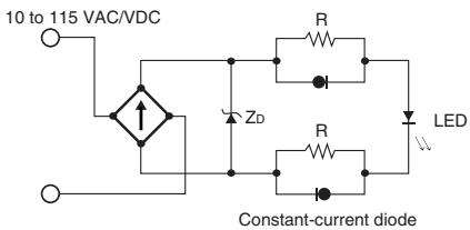
Circuit Connection Example
- Terminals 12 and 41 are connected internally and so connect terminals 11 and 42 for safety-circuit input. (GS-ET-19)
- Connect terminals 21 and 22 and terminals 51 and 52 in series when using as safety-circuit input (redundancy circuit for terminals 11 and 12 and terminals 41 and 42 above). Connect the terminals individually when using as auxiliary-circuit input (e.g., terminals 21 and 22 for safety-door open/closed monitoring and terminals 51 and 52 for monitoring the lock status).
- In the connection example on the right, terminals 21 and 22 and terminals 51 and 52 are used as auxiliary-circuit input.
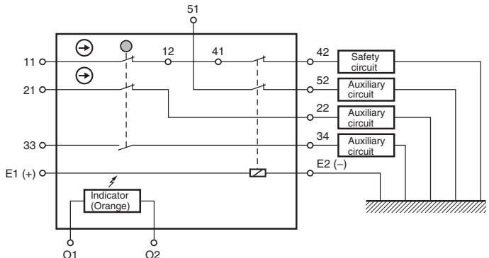
- Direct opening contacts used as safety-circuit input are indicated with the mark. Terminals 11 and 12 and terminals 21 and 22 are direct opening contacts.
- Connect the indicators in parallel to the auxiliary circuits or terminals E1 and E2.
If an indicator is connected in parallel to a direct opening contact, when the indicator breaks, a short-circuit current will be generated, possibly resulting in an installation malfunction.
- Do not switch standard loads for more than 2 circuits at the same time. Otherwise, the level of insulation may decrease.
- The 24-VDC solenoid has polarity. Be sure to connect terminals with the correct polarity.
Operation Method
Operation Principles
| Mechanical lock models | Operation Key Solenoid OFF Spring Lock plate | When the Operation Key is inserted, it is locked by the lock spring. The door will stay locked even if there is a power interruption. | The solenoid is released only when the lock is turned ON. |
| Solenoid lock models | Operation Key Solenoid Off Spring Lock plate | If the solenoid is OFF, the door will not be locked when the Operation Key is inserted. This means that the door can be opened and closed easily when replacing work-pieces or parts. | The door is locked only when the solenoid is turned ON. This means that the door will be unlocked if there is a power interruption and so this model cannot be used in systems that would maintain a hazardous state (e.g., systems requiring toxic gases, high temperatures, or gears that would continue to turn due to inertia). |
Nomenclature
Structure
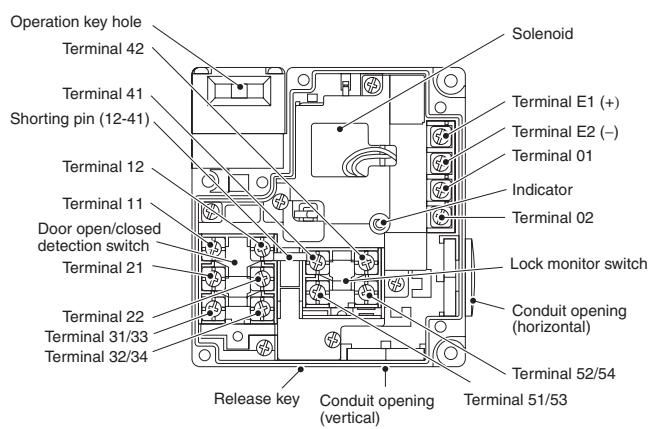
Note: Terminal numbers vary with the model.
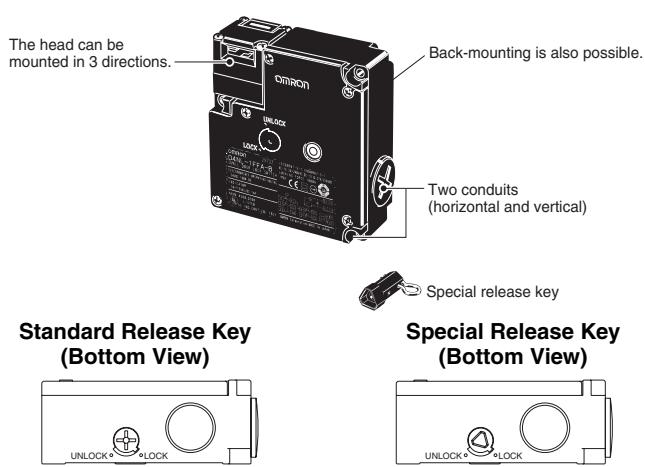
Indicates conditions where the Key is inserted and the lock is applied. Terminals 12 and 41 are connected internally (as per GS-ET-19).
Contact Form
| Model | Contact | Contact form | Operating pattern | Remarks | ||
| D4NL-□AF□□ | 1NC/1NO + 1NC/1NO | 11 12 41 42 33 53 54 | Lock position | Only NC contacts 11-12 and 41-42 have an approved direct opening mechanism. The terminals 11-42, 33-34, and 53-54 can be used as unlike poles. | ||
| 11-42 33-34 53-54 Stroke | ||||||
| Operation Key insertion completion position | ||||||
| D4NL-□BF□□ | 1NC/1NO + 2NC | 11 12 41 42 33 51 52 | Lock position | Only NC contacts 11-12, 41-42, and 51-52 have an approved direct opening mechanism. The terminals 11-42, 33-34, and 51-52 can be used as unlike poles. | ||
| 11-42 33-34 51-52 Stroke | ||||||
| Operation Key insertion completion position | ||||||
| D4NL-□CF□□ | 2NC + 1NC/1NO | 11 12 41 42 31 53 54 | Lock position | Only NC contacts 11-12, 31-32, and 41-42 have an approved direct opening mechanism. The terminals 11-42, 31-32, and 53-54 can be used as unlike poles. | ||
| 11-42 31-32 53-54 Stroke | ||||||
| Operation Key insertion completion position | ||||||
| D4NL-□DF□□ | 2NC + 2NC | 11 12 41 42 31 51 52 | Lock position | Only NC contacts 11-12, 31-32, 41-42, and 51-52 have an approved direct opening mechanism. The terminals 11-42, 31-32, and 51-52 can be used as unlike poles. | ||
| 11-42 31-32 51-52 Stroke | ||||||
| Operation Key insertion completion position | ||||||
| D4NL-□EF□□ | 2NC/1NO + 1NC/1NO | 11 12 41 42 31 53 54 | Lock position | Only NC contacts 11-12, 21-22, and 41-42 have an approved direct opening mechanism. The terminals 11-42, 21-22, 33-34, and 53-54 can be used as unlike poles. | ||
| 11-42 21-22 33-34 53-54 Stroke | ||||||
| Operation Key insertion completion position | ||||||
| D4NL-□FF□□ | 2NC/1NO + 2NC | 11 12 41 42 31 51 52 | Lock position | Only NC contacts 11-12, 21-22, 41-42, and 51-52 have an approved direct opening mechanism. The terminals 11-42, 21-22, 33-34, and 51-52 can be used as unlike poles. | ||
| 11-42 21-22 33-34 51-52 Stroke | ||||||
| Operation Key insertion completion position | ||||||
| D4NL-□GF□□ | 3NC + 1NC/1NO | 11 12 41 42 31 53 54 | Lock position | Only NC contacts 11-12, 21-22, 31-32, and 41-42 have an approved direct opening mechanism. The terminals 11-42, 21-22, 31-32, and 53-54 can be used as unlike poles. | ||
| 11-42 21-22 31-32 53-54 Stroke | ||||||
| Operation Key insertion completion position | ||||||
| D4NL-□HF□□ | 3NC + 2NC | 11 12 41 42 31 52 | Lock position | Only NC contacts 11-12, 21-22, 31-32, 41-42 and 51-52 have an approved direct opening mechanism. The terminals 11-42, 21-22, 31-32, and 51-52 can be used as unlike poles. | ||
| 11-42 21-22 31-32 51-52 Stroke | ||||||
| Operation Key insertion completion position | ||||||
Note: All units are in millimeters unless otherwise indicated
Switches
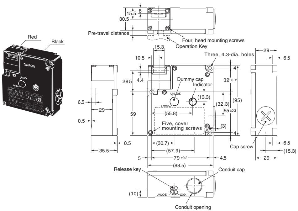
D4NL-□□□□-B
| Operating characteristics | D4NL-□□□□-B |
| Key insertion force | 15 N max. |
| Key extraction force | 30 N max. |
| Pre-travel distance | 9 mm max. |
| Movement before being locked | 3 mm min. |

D4NL-□□□□-B4
| Operating characteristics | D4NL-☐☐☐☐-B4 |
| Key insertion force | 15 N max. |
| Key extraction force | 30 N max. |
| Pre-travel distance | 9 mm max. |
| Movement before being locked | 3 mm min. |
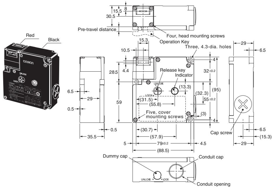
D4NL-□□□-BS
| Operating characteristics | D4NL-☐☐☐☐-BS |
| Key insertion force | 15 N max. |
| Key extraction force | 30 N max. |
| Pre-travel distance | 9 mm max. |
| Movement before being locked | 3 mm min. |
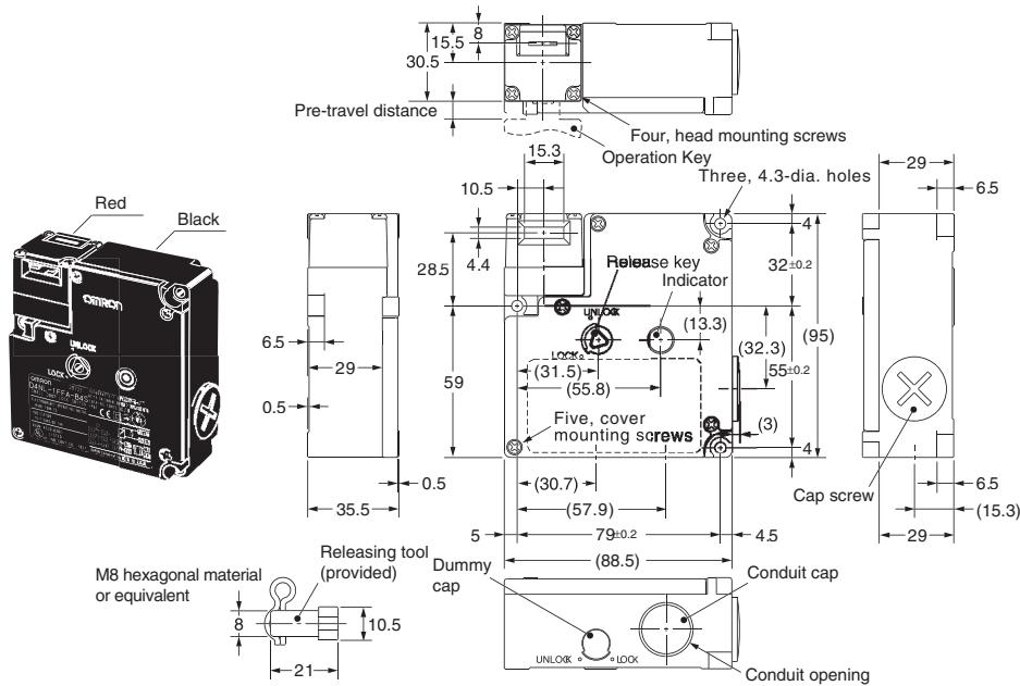
D4NL-□□□□-B4S
| Operating characteristics | D4NL-☐☐☐☐-B4S |
| Key insertion force | 15 N max. |
| Key extraction force | 30 N max. |
| Pre-travel distance | 9 mm max. |
| Movement before being locked | 3 mm min. |
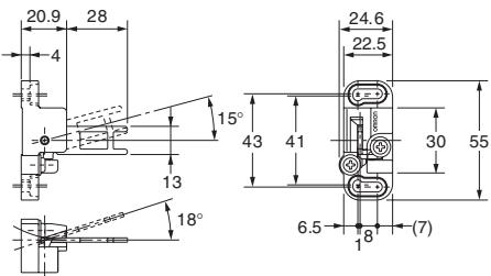
Operation Keys
Note: Unless otherwise specified, a tolerance of ± 0.4mm applies to all dimensions.
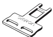
D4DS-K1
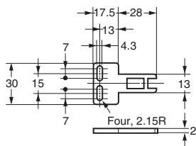
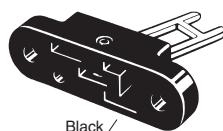
D4DS-K3
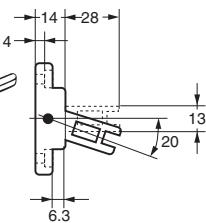
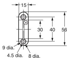
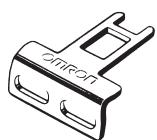
D4DS-K2
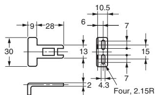
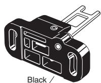
D4DS-K5
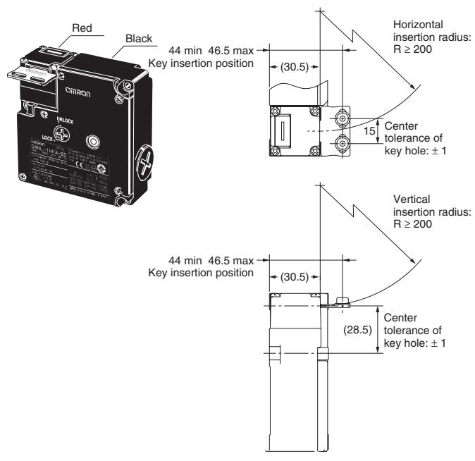
With Operation Key Inserted
D4NL + D4DS-K1
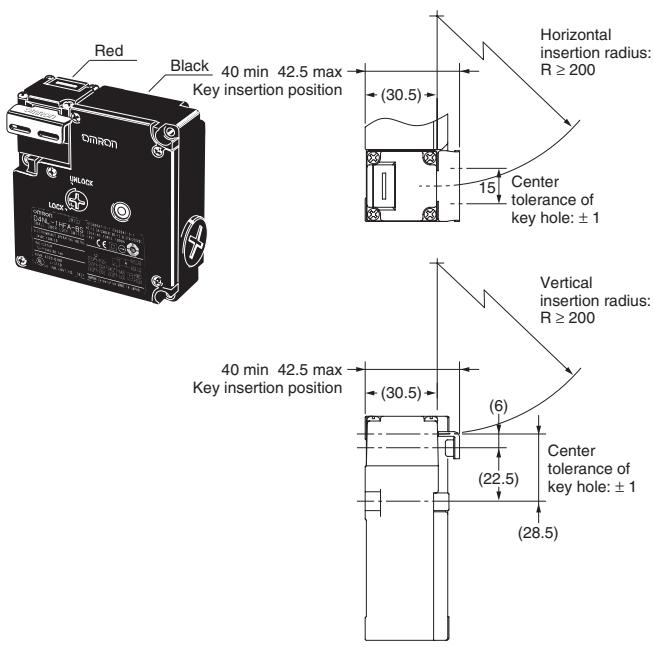
D4NL + D4DS-K2
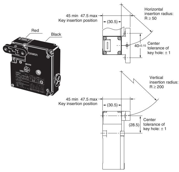
D4NL + D4DS-K3
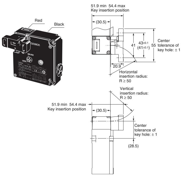
D4NL + D4DS-K5
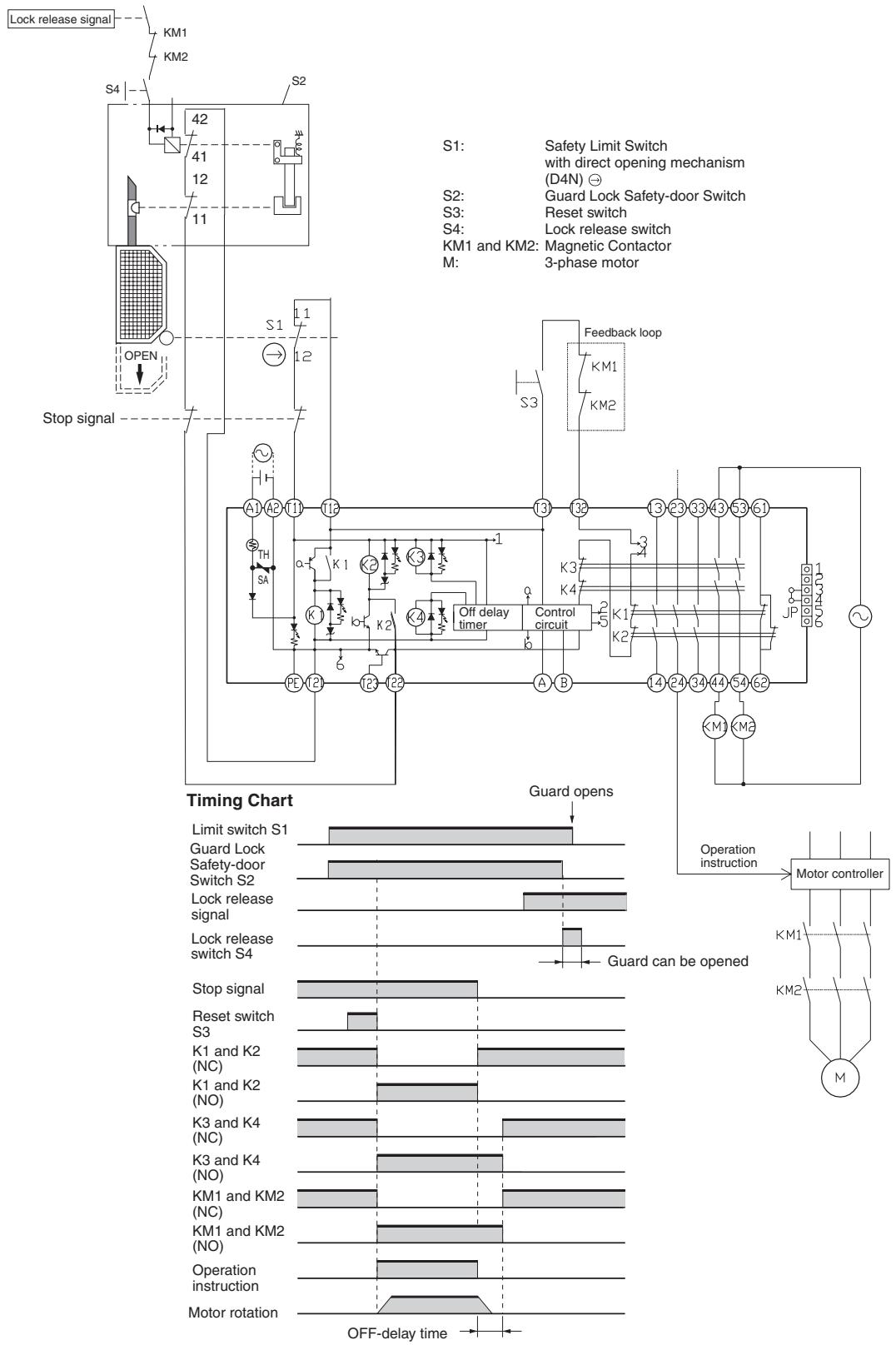
G9SA-321-T□ (24 VAC/VDC) + D4NL-□□□A-□, □□□B-□, □□□C-□
(Mechanical Lock Type) + D4D-520N Circuit Diagram
G9SA-301 (24 VAC/VDC) + D4NL-□□□G-□, □□□H-□, □□□J-□
(Solenoid Lock Type) + D4D-□520N Circuit Diagram
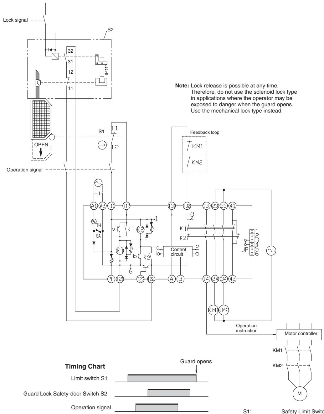
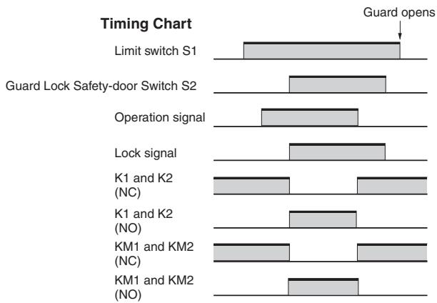
S1: Safety Limit Switch with direct opening mechanism (D4N)
S2: Guard Lock Safety-door Switch
KM1 and KM2: Magnetic Contactor
M: 3-phase motor

Caution
Do not insert the Operation Key with the door open. The machine may operate and damage may result.

Caution
Do not use metal connectors or conduits with this switch. Damage to the broken conduit hole may cause electric shock.

Caution
Change the head direction after changing the release key to the UNLOCK position. Do not change the head direction with the cover removed. Failure to observe these points may result in Switch malfunction or damage.
Holding Force
- Do not apply a force exceeding the specified holding force. Doing so may break the Switch and the machine may continue to operate.
- Either install another locking component (e.g., a stop) in addition to the Switch, or use a warning sticker or an indicator showing the lock status so that a force exceeding the specified holding force is not applied.
Safety Precautions
- The Switch contacts can be used for either standard loads or microloads. Once a contact has been used to switch a standard load, however, it cannot be used for a load of a smaller capacity. Doing so may result in roughening of the contact surface and contact reliability may be lost.
- Turn OFF the power before disassembling the Switch or touching any internal parts. Not doing so may result in electric shock.
- Mount the Operation Key in a location where it will not come in contact with users when the door is opened or closed. Otherwise, injury may result.
- Do not impose excessive force on the Operation Key when it is inserted into the Switch or drop the Switch with the Operation Key inserted. Otherwise, the Operation Key may be deformed or the Switch may be broken.
- Observe the specified insertion radius for the Operation Key and insert it in a direction perpendicular to the key hole.
- Do not use the Switch in starting circuits. (Use for safety confirmation signals.)
- When using the Switch in emergency-stop circuits or other safety circuits that have a direct impact on human lives, operate the NC contacts that have a direct opening mechanism in direct opening mode. For safety purposes, prevent easy removal by, for example, mounting the Switch and Operation Key with one-way screws or attaching a protective cover and warning label.
- In order to prevent short-circuit damage to the Switch, connect a fuse to the Switch in series. Use a fuse with a breaking current of 1.5 to 2 times the rated current. To conform to EN ratings, use a IEC269-compliant 10-A fuse type gI or gG.
- Turn the power OFF when wiring. After wiring is completed, be sure to mount the cover before use.
- In order to prevent burning due to overvoltage, insert a protective fuse in the solenoid circuits.
- Do not use the Switch where explosive gas, flammable gas, or any other dangerous gas may be present.
- Ensure that the load current does not exceed the rated current.
- Be sure to wire the terminals correctly.
- Be sure to evaluate the Switch under actual operating conditions after installation.
- Do not drop the package or the product. Do not disassemble internal parts.
Release Key
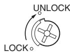
- The release key is used to unlock the Switch in case of emergency or if the power supply to the Switch stops.
- If the release key setting is changed from LOCK to UNLOCK using an appropriate tool, the lock will be released and the safety door can be opened (mechanical lock models only).
- After setting the release key to UNLOCK in order to, for example, change the head direction or perform maintenance, be sure to return it to LOCK setting before resuming operation.
- When the Switch is used for the door of a machine room to ensure the safety of people performing adjustment work inside, if the release key is set to UNLOCK, the door will not be locked when the door is closed and no power will be supplied to the equipment.
- Do not use the release key to start or stop machines.
- The auxiliary lock must only be released by authorized personnel.
- Do not impose a force exceeding 1 N·m on the release key screws. The release key may be damaged and may not operated properly.
- To prevent the release key from being used by unauthorized personnel, set it to LOCK and seal it with seal wax.
Mounting
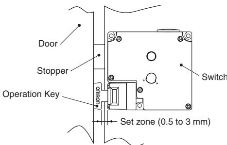
- Do not use the Switch as a stopper. To prevent the door from coming into contact with the flange of the Operation Key, be sure to mount the Switch with a stopper as shown above.
- When the Switch is used for a hinged door at a location near to the hinged side, where the Operation Key's insertion radius is comparatively small, if an attempt is made to open the door beyond the lock position, the force imposed will be much larger than for locations far from the hinged side, and the lock may be damaged.
Solenoid Lock Models
The solenoid lock locks the door only when power is supplied to the solenoid. Therefore, the door will be unlocked if the power supply to the solenoid stops. Therefore, do not use solenoid lock models for machines that may be operating and dangerous even after the machine stops operating.
Correct Use
Operating Environment
- This Switch is for indoor use only. Do not use it outdoors. Otherwise, it may malfunction.
- Do not use the Switch in the following locations:
- Locations subject to severe temperature changes
- Locations subject to high humidity levels or condensation
- Locations subject to severe shocks or vibrations
- Locations where the Switch may come in contact with metal dust, oil, or chemicals
- Locations subject to thinner, detergent, or other solvents.
- Although the Switch itself is protected from dust or water penetration, ensure that foreign material does not penetrate through the key hole on the head, otherwise Switch damage or malfunctioning may occur.
- Do not use the Switch submerged in oil or water, or in locations continuously subject to splashes of oil or water. Doing so may result in oil or water entering the Switch interior. (The IP67 degree of protection specification for the Switch pertains to the amount of water penetration after the Switch is submerged in water for a certain period of time.)
Life Expectancy
The life expectancy of the Switch will vary with the switching conditions. Before applying the Switch, test it under actual operating conditions and be sure to use it at a switching frequency that will not lower its performance.
Operation Key
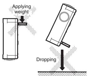
- Use the designated OMRON Operation Key with the Switch. Using another Operation Key may result in Switch damage.
- Do not impose excessive force on the Operation Key when it is inserted into the Switch or drop the Switch with the Operation Key inserted. Otherwise, the Operation Key may be deformed or the Switch may be broken.
Mounting
Tightening Torque
Be sure to tighten each screw of the Switch properly. Loose screws may result in malfunction.
| Type | Tightening torque |
| Terminal screw | 0.59 to 0.78 N·m |
| Cover mounting screw | 0.49 to 0.69 N·m |
| Head mounting screw | 0.49 to 0.59 N·m |
| Operation Key mounting screw | 2.35 to 2.75 N·m |
| Switch mounting screw | 0.49 to 0.69 N·m |
| Connector | 1.77 to 2.16 N·m |
| Cap screw | 1.27 to 1.67 N·m |
Switch and Operation Key Mounting
- Mount the Switch and Operation Key securely to the applicable tightening torque with M4 screws.
Mounting Hole Dimensions for Switch
Mounting Hole Dimensions for Operation Key
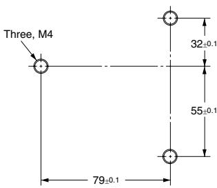
D4DS-K1-/K2 (horizontal/vertical mounting)
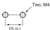
D4DS-K3 (adjustable mounting: horizontal)
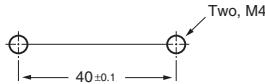
D4DS-K5 (adjustable mounting: vertical)
Two, M4

- If the Switch is back-mounted, the release key can only be operated from the bottom and the indicator cannot be used.
- Use the designated OMRON Operation Key with the Switch. Using another Operation Key may result in Switch damage.
- Ensure that the alignment offset between the Operation Key and the key hole does not exceed ± 1 mm.
Head Direction
By removing the four screws of the head, the mounting direction of the head can be changed. The head can be mounted in four directions.
Ensure that no foreign matter penetrates the interior of the Switch.
Securing the Door
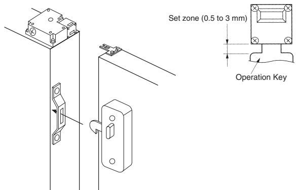
When the door is closed (with the Operation Key inserted), it may be pulled beyond the set zone because of, for example, the door's weight, or the door cushion rubber. Also, if a load is applied to the Operation Key, the door may fail to unlock properly. Use hooks to ensure that the door stays within the set zone (0.5 to 3 mm).
Wiring
Wiring Precautions
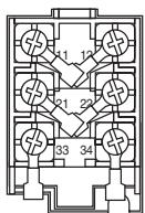
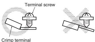
- When connecting to the terminals via insulating tube and M3.5 crimp terminals, cross the crimp terminals as shown above so that they do not rise up onto the case or the cover. Applicable lead wire size: AWG20 to AWG18 (0.5 to 0.75mm^2 ).
- When connecting lead wires directly to terminals, perform wiring securely so that there are no loose wire strands.
- Do not push crimp terminals into gaps in the case interior. Doing so may cause damage or deformation of the case.
- Use lead wires of an appropriate length. Not doing so may cause the cover to rise.
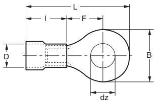
- Use crimp terminals not more than 0.5 ~mm in thickness. Otherwise, they will interfere with other components inside the case. The crimp terminals shown below are not more than 0.5 ~mm thick.
| Manufacturer | Model |
| J.S.T. | FV0.5-3.7 |
t: 0.5mm dz dia.: 3.7mm D dia.: 2.9mm B: 6.6mm L: 19mm F: 7.7mm I: 8.0mm
Conduit Opening
- Connect a recommended connector to the opening of the conduit and tighten the connector to the proper torque. The case may be damaged if an excessive tightening torque is applied.
- In order to ensure IP67 degree of protection, wrap sealing tape around the conduit end of the connector.
- Be sure that the outer diameter of the cable connected to the connector is correct.
- Attach and tighten a conduit cap to the unused conduit opening when wiring. The conduit cap is provided with the Switch.
Recommended Connectors
Use a connector with a screw section not exceeding 11mm , otherwise the screws will protrude into the case interior. The connectors given in the following table have connectors with screw sections not exceeding 11mm .
Use the following connectors to ensure conformance to IP67.
| Size | Manufacturer | Model | Applicable cable diameter |
| G1/2 | LAPP | ST-PF1/2 5380-1002 | 6.0 to 12.0 mm |
| Ohm Denki | OA-W1609 | 7.0 to 9.0 mm | |
| OA-W1611 | 9.0 to 11.0 mm | ||
| Pg13.5 | LAPP | S-13.5 5301-5030 | 5.0 to 12.0 mm |
| M20 | LAPP | ST-M20 *1.5 5311-1020 | 7.0 to 13.0 mm |
Use LAPP connectors together with seal packing (JPK-16, GP-13.5, or GPM20), and tighten with the applicable torque. Seal packing is sold separately.
Maintenance and Repairs
The user must not perform repairs or maintenance. Contact the machine manufacturer if repairs or maintenance are required.
Storage
Do not store the Switch in locations where harmful gases (e.g., H_2S , SO_2 , NH_3 , HNO_3 , or Cl_2 ) or dust are present, or in locations subject to high humidity levels.
Miscellaneous
- Do not touch the solenoid. The temperature of the solenoid increases when current is passed.
- In conditions requiring greater rigidity, sealing performance, and oil resistance, use OMRON's D4BL.
- Perform regular inspections.
Following the release of the D4NL, production of the D4DL will be terminated.
Date of Production Termination
Production of the D4DL Series will be terminated in November 2003.
Date of Substitute Product Release
Sale of the D4NL Series commenced in October 2002.
Product Replacement
The D4DL and D4NL have basically the same structure, and use the same mounting method and Operation Keys. There are differences, however, in the external appearance and the mounting sections.
Comparison of the D4DL and Substitute Products
| Model | D4NL-□ |
| Switch color | Very similar |
| Dimensions | Very similar |
| Wiring/connection | Significantly different |
| Mounting method | Very similar |
| Ratings/performance | Very similar |
| Operating characteristics | Very similar |
| Operating method | Completely compatible |
Dimensions
| Discontinued Model (D4DL) | 30.5 Operation Key Three, 4.3-dia. holes 4 28.5 Indicator (21) (32.3) (95) 5 (28.8) (3) (59) 79±0.2 (88.5) Conduit cap |
| Replacement products (D4NL Series) | 30.5 Operation Key Three, 4.3-dia. holes 4 28.5 Dummy cap Indicator (13.3) (32.3) (95) 5 (28.8) (3) (59) 79±0.2 (88.5) Conduit cap (10) UNLOCK |
Differences:The depth of the M4 mounting screw holes is 29mm for the D4NL, as opposed to 10mm for the D4DL. Therefore, when replacing the D4DL with the D4NL, use M4 screws that are 19mm longer than the ones used before.
List of Recommended Substitute Products
Switch
| D4DL product | Recommended substitute product | Substitute with M20 conduit |
| D4DL-1CFA-B | D4NL-1AFA-B, D4NL-1BFA-B | D4NL-4AFA-B, D4NL-4BFA-B |
| D4DL-2CFA-B | D4NL-2AFA-B, D4NL-2BFA-B | |
| D4DL-1DFA-B | D4NL-1CFA-B, D4NL-1DFA-B | D4NL-4CFA-B, D4NL-4DFA-B |
| D4DL-2DFA-B | D4NL-2CFA-B, D4NL-2DFA-B | |
| D4DL-1CFG-B | D4NL-1AFG-B, D4NL-1BFG-B | D4NL-4AFG-B, D4NL-4BFG-B |
| D4DL-2CFG-B | D4NL-2AFG-B, D4NL-2BFG-B | |
| D4DL-1DFG-B | D4NL-1CFG-B, D4NL-1DFG-B | D4NL-4CFG-B, D4NL-4DFG-B |
| D4DL-2DFG-B | D4NL-2AFB-B, D4NL-2BFB-B | |
| D4DL-1DFB-B | D4NL-1CFB-B, D4NL-1DFB-B | D4NL-4CFB-B, D4NL-4DFB-B |
| D4DL-2DFB-B | D4NL-2CFB-B, D4NL-2DFB-B | |
| D4DL-1CFH-B | D4NL-1AFH-B, D4NL-1BFH-B | D4NL-4AFH-B, D4NL-4BFH-B |
| D4DL-2CFH-B | D4NL-2AFH-B, D4NL-2BFH-B | |
| D4DL-1DFH-B | D4NL-1CFH-B, D4NL-1DFH-B | D4NL-4CFH-B, D4NL-4DFH-B |
| D4DL-2DFH-B | D4NL-2CFH-B, D4NL-2DFH-B | |
| D4DL-1CFC-EW | D4NL-1AFC-E, D4NL-1BFC-E | D4NL-4AFC-E, D4NL-4BFC-E |
| D4DL-2CFC-EW | D4NL-2AFC-E, D4NL-2BFC-E | |
| D4DL-1DFC-EW | D4NL-1CFC-E, D4NL-1DFC-E | D4NL-4CFC-E, D4NL-4DFC-E |
| D4DL-2DFC-EW | D4NL-2CFC-E, D4NL-2DFC-E | |
| D4DL-1CFJ-EW | D4NL-1AFJ-E, D4NL-1BFJ-E | D4NL-4AFJ-E, D4NL-4BFJ-E |
| D4DL-2CFJ-EW | D4NL-2AFJ-E, D4NL-2BFJ-E | |
| D4DL-1DFJ-EW | D4NL-1CFJ-E, D4NL-1DFJ-E | D4NL-4CFJ-E, D4NL-4DFJ-E |
| D4DL-2DFJ-EW | D4NL-2CFJ-E, D4NL-2DFJ-E | |
| D4DL-1CFA-B-HT | D4NL-1AFA-B4, D4NL-1BFA-B4 | D4NL-4AFA-B4, D4NL-4BFA-B4 |
| D4DL-2CFA-B-HT | D4NL-2AFA-B4, D4NL-2BFA-B4 | |
| D4DL-1DFA-B-HT | D4NL-1CFA-B4, D4NL-1DFA-B4 | D4NL-4CFA-B4, D4NL-4DFA-B4 |
| D4DL-2DFA-B-HT | D4NL-2CFA-B4, D4NL-2DFA-B4 | |
| D4DL-1CFG-B-HT | D4NL-1AFG-B4, D4NL-1BFG-B4 | D4NL-4AFG-B4, D4NL-4BFG-B4 |
| D4DL-2CFG-B-HT | D4NL-2AFG-B4, D4NL-2BFG-B4 | |
| D4DL-1DFG-B-HT | D4NL-1CFG-B4, D4NL-1DFG-B4 | D4NL-4CFG-B4, D4NL-4DFG-B4 |
| D4DL-2DFG-B-HT | D4NL-2CFG-B4, D4NL-2DFG-B4 |
Note: With standard products, terminals 12 and 41 are connected with a shorting pin. In cases where D4DL terminals 11 and 12 and terminals 41 and 42 are currently being used independently, remove the shorting pin.
Note: Operation Key
D4DS-K1
D4DS-K2
D4DS-K3
D4DS-K5
All of the above Operation Keys can be used with the D4NL.
ALL DIMENSIONS SHOWN ARE IN MILLIMETERS.
To convert millimeters into inches, multiply by 0.03937. To convert grams into ounces, multiply by 0.03527.
- Guard Lock Safety-door Switch
- D4NL
- Lead-free,
- Environment-friendly Design
- Model Number Structure
- Model Number Legend
- Switch
- Conduit Size
- Built-in Switch (with Door Open/Closed Detection Switch and Lock Monitor Switch Contacts)
- Head Mounting Direction and Material
- Door Lock and Release
- Indicator
- Release Key Type
- Release Key Position
- Operation Key
- Operation Key Type
- Specifications
- Standards and EC Directives
- Applicable EC Directives and Standards
- Approved Standard Ratings
- UL/CSA (UL508, CSA C22.2 No. 14)
- Indicator
- Internal Circuit Diagram
- Circuit Connection Example
- Operation Method
- Operation Principles
- Nomenclature
- Switches
- Operation Keys
- With Operation Key Inserted
- Caution
- Holding Force
- Safety Precautions
- Release Key
- Mounting
- Solenoid Lock Models
- Correct Use
- Operating Environment
- Life Expectancy
- Tightening Torque
- Head Direction
- Securing the Door
- Wiring
- Wiring Precautions
- Conduit Opening
- Recommended Connectors
- Maintenance and Repairs
- Storage
- Miscellaneous
- Date of Production Termination
- Date of Substitute Product Release
- Product Replacement
- Comparison of the D4DL and Substitute Products
- List of Recommended Substitute Products
Marque : OMRON
Modèle : D4NL
Catégorie : Capteurs de position