
A165K - Interrupteur électrique OMRON - Notice d'utilisation et mode d'emploi gratuit
Retrouvez gratuitement la notice de l'appareil A165K OMRON au format PDF.
| Type de produit | Interrupteur électrique à clé (Key-type Selector Switch) |
| Marque | OMRON |
| Modèle | A165K |
| Diamètre de montage | 16 mm |
| Profondeur sous panneau | Moins de 28,5 mm |
| Poids (modèle DPDT) | Environ 26,5 g |
| Indice de protection | IP65 résistant à l'huile |
| Nombre de positions | 2 ou 3 crans |
| Mode de retour | Manuel ou automatique selon modèle |
| Configuration des contacts | SPDT ou DPDT (selon modèle) |
| Courant nominal (contact) | 5 A à 125 VAC, 3 A à 250 VAC, 3 A à 30 VDC |
| Charge minimale applicable | 1 mA à 5 VDC |
| Température de fonctionnement | -10°C à 55°C |
| Température de stockage | -25°C à 65°C |
| Humidité ambiante | 35% à 85% |
| Durée de vie mécanique | 250 000 opérations minimum |
| Durée de vie électrique | 100 000 opérations minimum |
| Durée de vie de la clé | 10 000 opérations minimum |
| Normes de sécurité | UL/cUL (UL508), EN60947-5-1, IEC947-5-1 |
| Classe de protection électrique | Classe II |
| Matériau du boîtier | Résine (non spécifié, estimation plastique) |
| Accessoires fournis | 2 clés, écrou de montage, joint |
| Pièces détachées disponibles | Clé de rechange (A165K-KEY), extracteur (A16Z-5080), bouchons de panneau |
| Nettoyage | Chiffon sec, éviter solvants |
FOIRE AUX QUESTIONS - A165K OMRON
Questions des utilisateurs sur A165K OMRON
0 question sur cet appareil. Repondez a celles que vous connaissez ou posez la votre.
Poser une nouvelle question sur cet appareil
Téléchargez la notice de votre Interrupteur électrique au format PDF gratuitement ! Retrouvez votre notice A165K - OMRON et reprennez votre appareil électronique en main. Sur cette page sont publiés tous les documents nécessaires à l'utilisation de votre appareil A165K de la marque OMRON.
MODE D'EMPLOI A165K OMRON
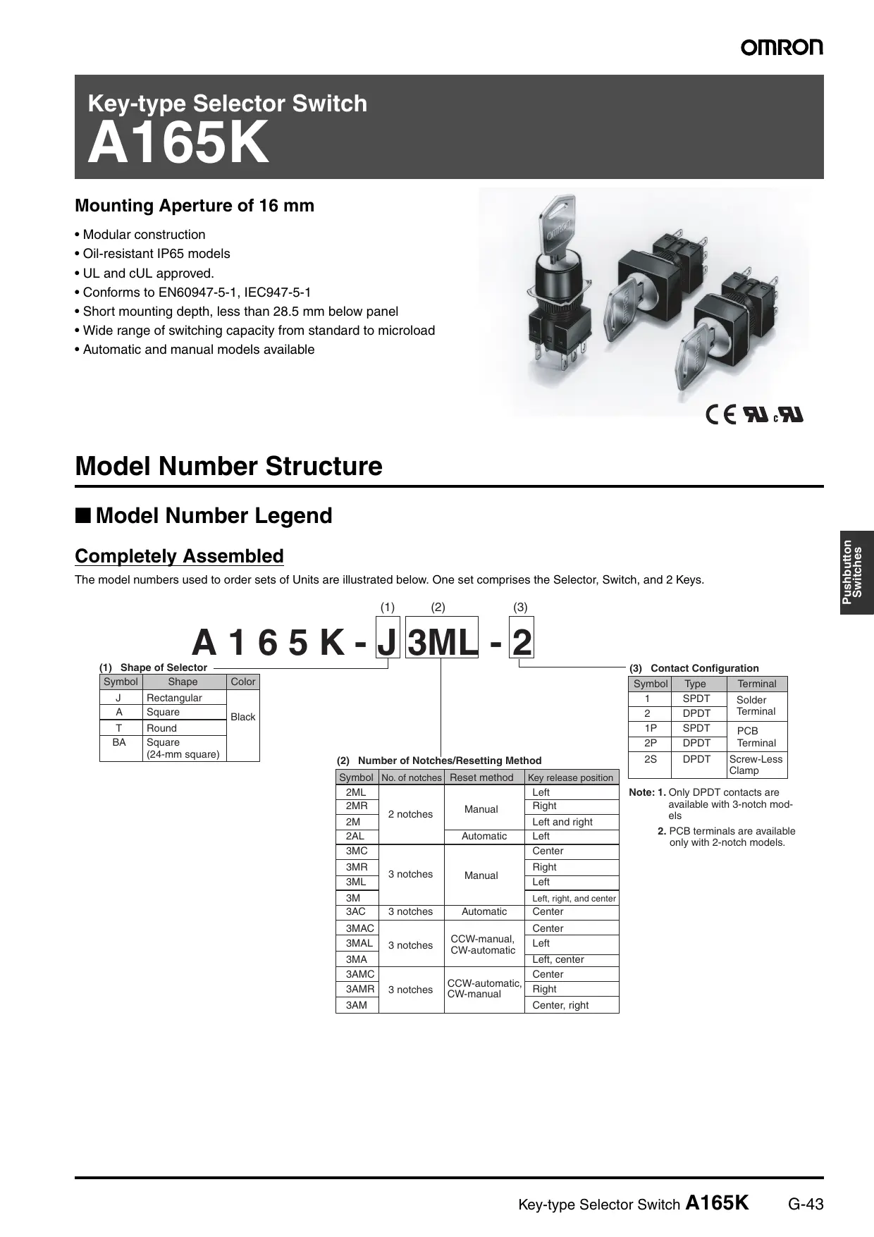
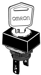
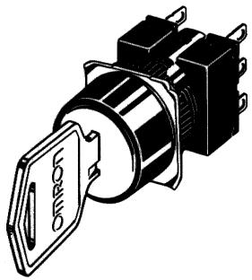
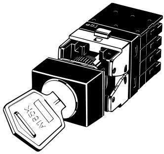
Key-type Selector Switch
A165K
Mounting Aperture of 16 mm
- Modular construction
- Oil-resistant IP65 models
- UL and cUL approved.
- Conforms to EN60947-5-1, IEC947-5-1
- Short mounting depth, less than 28.5 mm below panel
- Wide range of switching capacity from standard to microload
• Automatic and manual models available
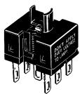
natural_image
Illustration of various black industrial push-button switches with visible fuses and metal contacts (no text or symbols)CE RU c RU
Model Number Structure
■ Model Number Legend
Completely Assembled
The model numbers used to order sets of Units are illustrated below. One set comprises the Selector, Switch, and 2 Keys.
A 1 6 5 K - J 3ML - 2
(1) Shape of Selector
| Symbol | Shape | Color |
| J | Rectangular | Black |
| A | Square | |
| T | Round | |
| BA | Square(24-mm square) |
(2) Number of Notches/Resetting Method
| Symbol | No. of notches | Reset method | Key release position |
| 2ML | 2 notches | Manual | Left |
| 2MR | Right | ||
| 2M | Left and right | ||
| 2AL | Automatic | Left | |
| 3MC | 3 notches | Manual | Center |
| 3MR | Right | ||
| 3ML | Left | ||
| 3M | Left, right, and center | ||
| 3AC | 3 notches | Automatic | Center |
| 3MAC | 3 notches | CCW-manual, CW-automatic | Center |
| 3MAL | Left | ||
| 3MA | Left, center | ||
| 3AMC | 3 notches | CCW-automatic, CW-manual | Center |
| 3AMR | Right | ||
| 3AM | Center, right |
(3) Contact Configuration
| Symbol | Type | Terminal |
| 1 | SPDT | Solder Terminal |
| 2 | DPDT | |
| 1P | SPDT | PCB Terminal |
| 2P | DPDT | |
| 2S | DPDT | Screw-Less Clamp |
Note: 1. Only DPDT contacts are available with 3-notch models
2. PCB terminals are available only with 2-notch models.
Subassembled
1. Selector
1. Flange Shape
J: Rectangular
A: Square
T: Round
BA: Square (24-mm square)
2. Number of Notches/Reset Method/Key Release Position
2ML: 2 notches/Manual/Left
2MR: 2 notches/Manual/Right
2M: 2 notches/Manual/Right and left
2AL: 2 notches/Automatic/Left
3MC: 3 notches/Manual/Center
3MR: 3 notches/Manual/Right
3ML: 3 notches/Manual/Left
3M: 3 notches/Manual/Right, left, and center
3AC: 3 notches/Automatic/Center
2. Switch (Same as for Knob-type Selector Switches)
1. Number of Notches
2N: 2 notches
3N: 3 notches
2. Contacts
1: SPDT
2: DPDT
3. Terminals
None: Solder terminals (tab terminals #110)
■ List of Models
Ordering as a Set
The model numbers used to order sets of Units are given in the following tables. One set comprises the Selector and Switch.
Solder Terminals
A165K-J (Rectangular) Models
IP65 Oil-resistant
| Number of notches | Output | Reset method | Key release position | Model |
| 2 notches | SPDT | Manual | Left | A165K-J2ML-1 |
| Right | A165K-J2MR-1 | |||
| Left and right | A165K-J2M-1 | |||
| Automatic | Left | A165K-J2AL-1 | ||
| DPDT | Manual | Left | A165K-J2ML-2 | |
| Right | A165K-J2MR-2 | |||
| Left and right | A165K-J2M-2 | |||
| Automatic | Left | A165K-J2AL-2 | ||
| 3 notches | DPDT | Manual | Center | A165K-J3MC-2 |
| Right | A165K-J3MR-2 | |||
| Left | A165K-J3ML-2 | |||
| Left, right, and center | A165K-J3M-2 |
A165K-A (Square) Models
IP65 Oil-resistant
| Number of notches | Output | Reset method | Key release position | Model |
| 2 notches | SPDT | Manual | Left | A165K-A2ML-1 |
| Right | A165K-A2MR-1 | |||
| Left and right | A165K-A2M-1 | |||
Automatic  | Left | A165K-A2AL-1 | ||
| DPDT | Manual | Left | A165K-A2ML-2 | |
| Right | A165K-A2MR-2 | |||
| Left and right | A165K-A2M-2 | |||
Automatic  | Left | A165K-A2AL-2 | ||
| 3 notches | DPDT | Manual | Center | A165K-A3MC-2 |
| Right | A165K-A3MR-2 | |||
| Left | A165K-A3ML-2 | |||
| Left, right, and center | A165K-A3M-2 |
IP65 Oil-resistant
| Number of notches | Output | Reset method | Key release position | Model |
| 2 notches | SPDT | Manual | Left | A165K-T2ML-1 |
| Right | A165K-T2MR-1 | |||
| Left and right | A165K-T2M-1 | |||
| Automatic | Left | A165K-T2AL-1 | ||
| DPDT | Manual | Left | A165K-T2ML-2 | |
| Right | A165K-T2MR-2 | |||
| Left and right | A165K-T2M-2 | |||
| Automatic | Left | A165K-T2AL-2 | ||
| 3 notches | DPDT | Manual | Center | A165K-T3MC-2 |
| Right | A165K-T3MR-2 | |||
| Left | A165K-T3ML-2 | |||
| Left, right, and center | A165K-T3M-2 |
Ordering Individually
Selectors and Switches can be ordered separately. Combinations that are not available as sets can be created using individual Units. Also, store the parts as spares for maintenance and repairs.
Selectors
| Appearance | Number of notches | Reset method | Key release position | Model |
Rectangular (A165K-J) | 2 notches | Manual | A165K-J2ML | |
| A165K-J2MR | ||||
| A165K-J2M | ||||
| Automatic | A165K-J2AL | |||
| 3 notches | Manual | A165K-J3MC | ||
| A165K-J3MR | ||||
| A165K-J3ML | ||||
| A165K-J3M | ||||
| Automatic | A165K-J3AC | |||
| 3 notches | Mixed-operation | A165K-J3MAC | ||
| A165K-J3MAL | ||||
| A165K-J3MA | ||||
| Mixed-operation | A165K-J3AMC | |||
| A165K-J3AMR | ||||
| A165K-J3AM | ||||
Square (A165K-A)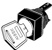 | 2 notches | Manual | A165K-A2ML | |
| A165K-A2MR | ||||
| A165K-A2M | ||||
| Automatic | A165K-A2AL | |||
| 3 notches | Manual | A165K-A3MC | ||
| A165K-A3MR | ||||
| A165K-A3ML | ||||
| A165K-A3M | ||||
| Automatic | A165K-A3AC | |||
| 3 notches | Mixed-operation | A165K-A3MAC | ||
| A165K-A3MAL | ||||
| A165K-A3MA | ||||
| Mixed-operation | A165K-A3AMC | |||
| A165K-A3AMR | ||||
| A165K-A3AM | ||||
Round (A165K-T)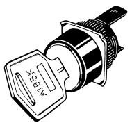 | 2 notches | Manual | A165K-T2ML | |
| A165K-T2MR | ||||
| A165K-T2M | ||||
| Automatic | A165K-T2AL | |||
| 3 notches | Manual | A165K-T3MC | ||
| A165K-T3MR | ||||
| A165K-T3ML | ||||
| A165K-T3M | ||||
| Automatic | A165K-T3AC | |||
| 3 notches | Mixed-operation | A165K-T3MAC | ||
| A165K-T3MAL | ||||
| A165K-T3MA | ||||
| Mixed-operation | A165K-T3AMC | |||
| A165K-T3AMR | ||||
| A165K-T3AM |
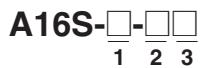
Switches
| Appearance | Classification | Model | |||
 | Switch | 2 notches | SPDT | Solder terminal | A16S-2N-1 |
| DPDT | A16S-2N-2 | ||||
| 3 notches | DPDT | A16S-3N-2 | |||
 | 2 notches | SPDT | PCB terminal | A16S-2N-1P | |
| DPDT | A16S-2N-2P | ||||
Switches with Screw-Less Clamp
| Appearance | Classification | Model | Remarks | |||
 | Common to general load and micro load. | DPDT | 2 notches | Non-lighted | A16-2S | Common to ones for pushbutton switches. |
| 3 notches | A16S-3N-2LS | --- | ||||
Accessories (Order Separately)
Accessories
| Name | Appearance | Classification | Model | Remarks |
| Panel Plugs |  | Rectangular | A16ZJ-3003 | Used for covering the panel cutouts for future panel expansion.Degree of protection: IP40 |
| Square | A16ZA-3003 | |||
| Round | A16ZT-3003 |
Tools
| Name | Appearance | Model | Applicable types | Remarks | ||||
| Pushbutton Switch | Knob-type Selector Switch | Key-type Selector Switch | Emergency Stop Switch | Indicator | ||||
| Screw Fitting |  | A16Z-3004 | Yes | Yes | Yes | Yes | Yes | Convenient for ganged installation.Tighten to a torque of 0.98 N·m |
| Extractor |  | A16Z-5080 | Yes | Yes | Yes | Yes | Yes | Convenient for extracting the Switches and Lamps. |
Key
| Appearance | Model | |
 | A165K-KEY | |
Note: Two Keys are provided.
Specifications
■ Approved Standards
| Agency | Standards | File No. |
| UL, cUL (See note.) | UL508 | E41515 |
| --- | EN60947-5-1 | --- |
Note: cUL: CSA, C22.2 No. 14
■ Approved Standard Ratings
UL, cUL (File No. E41515)
5 A at 125 VAC, 3 A at 250 VAC (general use)
3 A at 30 VDC (resistive)
EN60947-5-1 (Low Voltage Directive)
3 A at 250 VAC (AC12), 3 A at 30 VDC (DC12)
■ Ratings
Contacts
| AC resistive load | DC resistive load |
| 3 A at 250 VAC5 A at 125 VAC | 3 A at 30 VDC |
Minimum applicable load: 1 mA at 5 VDC
Rated values are obtained from tests conducted under the following conditions.
- Load: Resistive load
- Mounting conditions: No vibration and no shock
- Temperature: 20 ± 2^
- Operating frequency: 20 times/min
■ Characteristics
| Item | Key-type Selector Switch | |
| Allowable operating frequency | Mechanical | 20 operations/minute max. |
| Electrical | 10 operations/minute max. | |
| Insulation resistance | 100 MΩ min. (at 500 VDC) | |
| Dielectric strength | 1,000 VAC, 50/60 Hz for 1 min between terminals of same polarity2,000 VAC, 50/60 Hz for 1 min between terminals of different polarity and also between each terminal and ground | |
| Vibration resistance | Malfunction | 10 to 55 Hz, 1.5-mm double amplitude (malfunction within 1 ms) |
| Shock resistance | Mechanical | 500 m/s ^2 |
| Malfunction | 150 m/s ^2 max. (malfunction within 1 ms) | |
| Durability | Mechanical | 250,000 operations min. (durability of key: 10,000 operations min.) |
| Electrical | 100,000 operations min. | |
| Ambient temperature | Operating: -10°C to 55°C (with no icing or condensation)Storage: -25°C to 65°C (with no icing or condensation) | |
| Ambient humidity | Operating: 35% to 85% | |
| Electric shock protection class | Class II | |
| PTI (tracking characteristic) | 175 | |
| Degree of contamination | 3 (IEC947-5-1) | |
| Weight | Approx. 26.5 g (in the case of a DPDT switch key) | |
Note: Set and reset constitute one operation.
Screw-less Clamp
| Item | Screw-less Clamp | ||||
| Recommended wire size | 0.5 mm2 twisted wire or 0.8 mm-dia. solid wire | ||||
| Usable wires and tensile strength | Twisted wire | 0.3mm2 | 0.5 mm2 | 0.75 mm2 | 1.25 mm2 |
| Solid wire | 0.5 mm dia. | 0.8 mm dia. | 1.0 mm dia. | --- | |
| Tensile strength | 10 N | 20 N | 30 N | 40 N | |
| Length of exposed wire | 10 ±1 mm | ||||
■ Operating Characteristics
| Features\Type | Key-type Selector Switch | |
| 2 notches | 3 notches | |
| Operating force (OF) max. | 9.8 N·m | |
| Set position (SP) | 90 ± 5^ | 45^+10/_0 |
■ Operation Angle
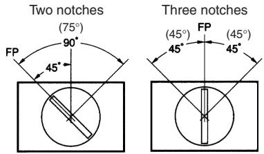
text_image
Two notches (75°) 90° FP 45° Three notches (45°) FP (45°)Note: The angle used for automatic reset is shown in parentheses.
■ Contact Form
| Name | Contact |
| DPDT |
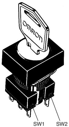
text_image
OMRON SW1 SW2| Notch | Contact | ||||
| SPDT | DPDT | ||||
| Position | SW | Position | SW1 | SW2 | |
| 2 notches | |||||
| 3 notches | --- | ||||
Nomenclature
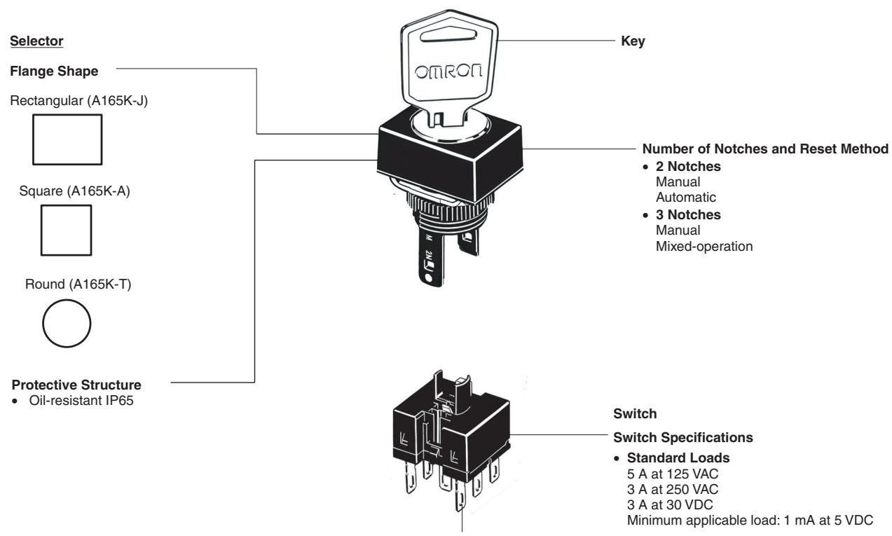
text_image
Selector Flange Shape Rectangular (A165K-J) Square (A165K-A) Round (A165K-T) Protective Structure Oil-resistant IP65 Key Number of Notches and Reset Method • 2 Notches Manual Automatic • 3 Notches Manual Mixed-operation Switch Switch Specifications • Standard Loads 5 A at 125 VAC 3 A at 250 VAC 3 A at 30 VDC Minimum applicable load: 1 mA at 5 VDCTerminal Type
- Solder terminals (tab terminals #110)
- PCB terminals
Note: All units are in millimeters unless otherwise indicated.
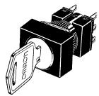
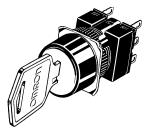
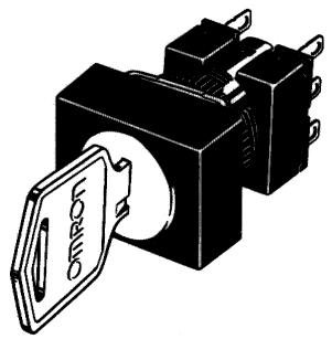
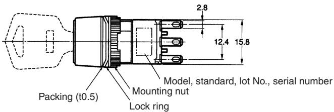
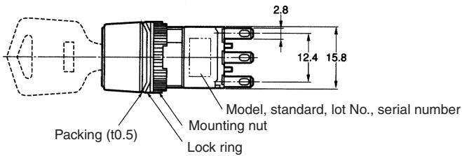
■ Key-type Selector Switches
Rectangular
A165K-J
Solder terminals (tab terminals #110)
natural_image
Illustration of a black electrical component with a metallic tag labeled 'DIAGON' (no other text or symbols)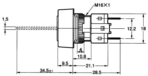
text_image
M16×1 1.5 12.2 18 4 10.8 9.5 21.1 34.5±1 28.5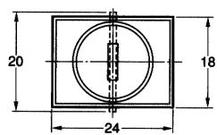
text_image
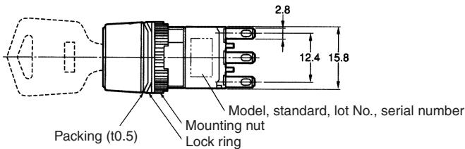
2.8 12.4 15.8 Model, standard, lot No., serial number Mounting nut Lock ring Packing (t0.5)Note: See page 14 for panel cutouts.
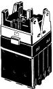
Square
A165K-A
Solder terminals
(tab terminals #110)
natural_image
Illustration of a black industrial electrical switch with a labeled component (no text or symbols present)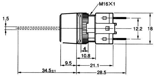
text_image
1.5 M16×1 12.2 18 4 10.8 9.5 21.1 34.5±1 28.5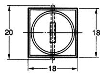
text_image
Packing (t0.5) Mounting nut Lock ring 2.8 12.4 15.8 Model, standard, lot No., serial numberNote: See page 14 for panel cutouts.
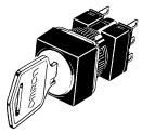
Round
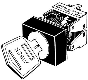
A165K-T
Solder terminals
(tab terminals #110)
natural_image
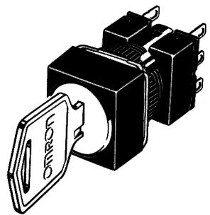
Illustration of a black-and-white photo of a mechanical switch with a key inserted, no text or symbols present.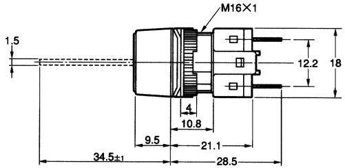
text_image
M16×1 1.5 12.2 18 4 10.8 9.5 21.1 34.5±1 28.5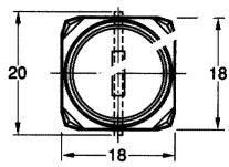
text_image
2,8 12.4 15.8 Model, standard, lot No., serial number Mounting nut Lock ring Packing (t0.5)Note: See page 14 for panel cutouts.
The following diagrams show the rectangular model as a representative example.
Rectangular
A165K-J
PCB terminals
text_image
A150F 1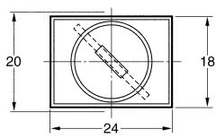
Note: See page 14 for panel cutouts.
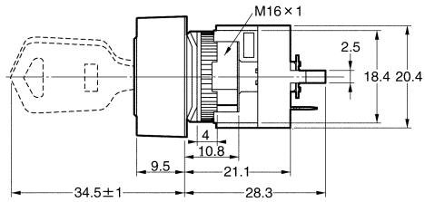
text_image
M16×1 2.5 18.4 20.4 4 10.8 9.5 21.1 34.5±1 28.3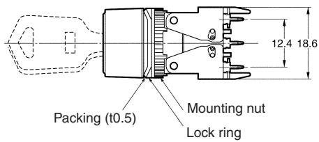
text_image
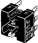
Packing (t0.5) Mounting nut Lock ring 12.4 18.6Rectangular
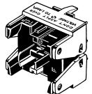
A165K□-2S
Screw-Less Clamp
natural_image
Technical line drawing of an electrical switchgear assembly (no text or symbols)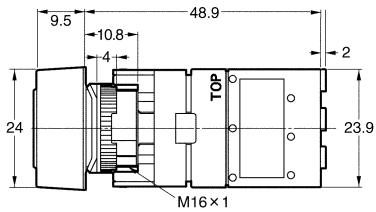
text_image
9.5 10.8 4 48.9 2 24 TOP M16×1 23.9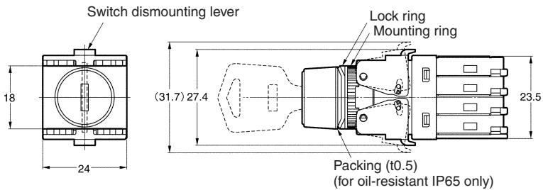
text_image
Switch dismounting lever 18 24 (31.7) 27.4 Lock ring Mounting ring Packing (t0.5) (for oil-resistant IP65 only) 23.5■ Terminal Arrangement
Models with Solder Terminals without Reduced-voltage Lighting
Lamp terminals are not provided with the Non-lighted Knob-type Selector Switches and Key-type Selector Switches.
Lighted SPDT Switches
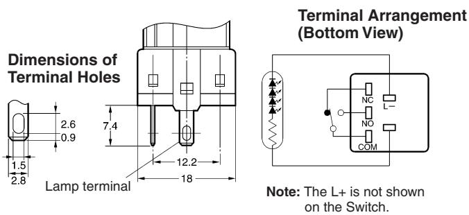
text_image
Dimensions of Terminal Holes Lamp terminal 7.4 12.2 18 2.6 0.9 1.5 2.8 Terminal Arrangement (Bottom View) Note: The L+ is not shown on the Switch.Lighted DPDT Switches
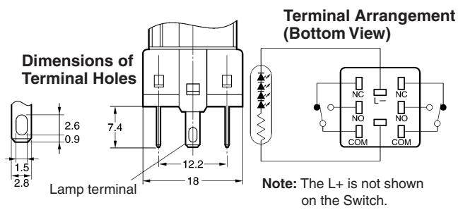
text_image
Dimensions of Terminal Holes 2.6 0.9 1.5 2.8 Lamp terminal 7.4 12.2 18 Terminal Arrangement (Bottom View) Note: The L+ is not shown on the Switch.Non-lighted SPDT Switches
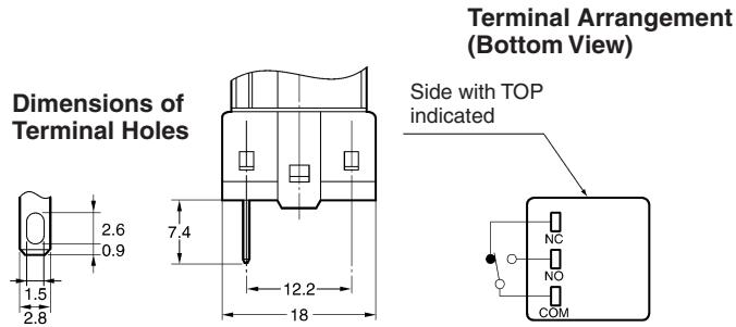
text_image
Dimensions of Terminal Holes 2.6 0.9 1.5 2.8 7.4 12.2 18 Terminal Arrangement (Bottom View) Side with TOP indicated NC NO COMNon-lighted DPDT Switches
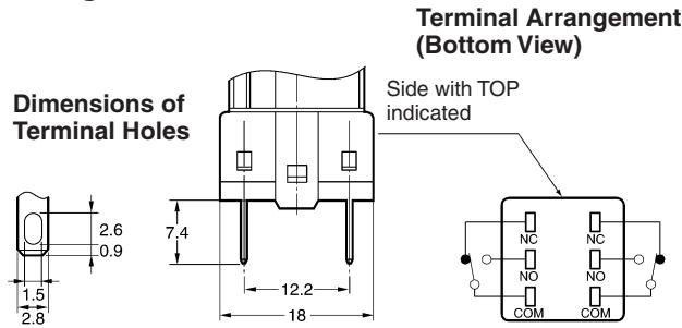
text_image
Dimensions of Terminal Holes 7.4 12.2 18 2.6 0.9 1.5 2.8 Terminal Arrangement (Bottom View) Side with TOP indicated NC NC NO NO COM COMLighted Models with PCB Terminals
Lighted SPDT Switches
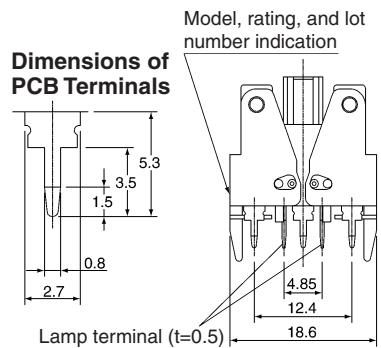
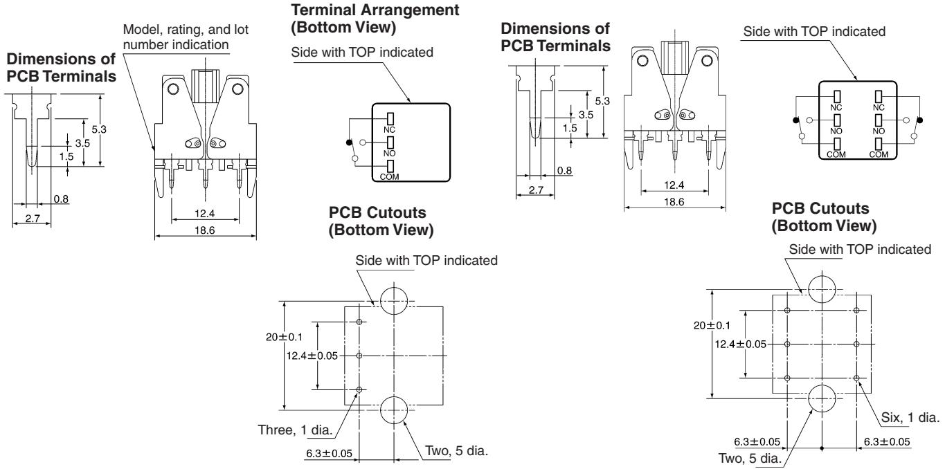
text_image
Dimensions of PCB Terminals Model, rating, and lot number indication 2.7 5.3 3.5 1.5 0.8 4.85 12.4 18.6 Lamp terminal (t=0.5)Terminal Arrangement (Bottom View)
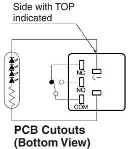
text_image
Side with TOP indicated PCB Cutouts (Bottom View)Lighted DPDT Switches
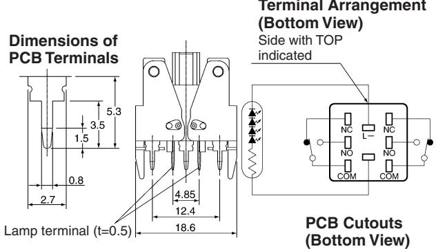
text_image
Dimensions of PCB Terminals 5.3 1.5 3.5 0.8 2.7 Lamp terminal (t=0.5) 4.85 12.4 18.6 Terminal Arrangement (Bottom View) Side with TOP indicated NC NC NO NO COM COM PCB Cutouts (Bottom View)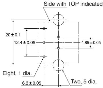
text_image
Side with TOP indicated 20±0.1 12.4±0.05 4.85±0.05 Eight, 1 dia. 6.3±0.05 Two, 5 dia.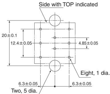
text_image
Side with TOP indicated 20±0.1 12.4±0.05 4.85±0.05 Eight, 1 dia. 6.3±0.05 6.3±0.05 Two, 5 dia.Note: For details of the terminal arrangement for Screw-Less Clamps, refer to the corresponding section for the A16.
Non-lighted Models with PCB Terminals
Lamp terminals are not provided with the Non-lighted Knob-type Selector Switches and Key-type Selector Switches.
Non-lighted SPDT Switches
Non-lighted DPDT Switches
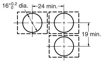
Panel Cutouts
Models with Solder Terminals
Rectangular
A165□-J
(Top View)
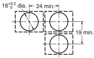
text_image
16⁺⁰·² dia. 24 min. 19 min.Square A165□-A
Round A165□-T
(Top View)
text_image
16⁺⁰·²₀ dia. 19 min. 19 min.Note: 1. Make sure the thickness of the mounting panel is 0.5 to 3.2 mm.
2. If the panel is to be finished with coating, etc., make sure that the panel meets the specified dimensions after coating.
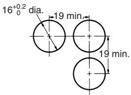
Models with PCB Terminals
Rectangular
A165□-J
(Top View)
text_image
16⁺⁰·² dia. 24 min. 19 min.Square A165□-A
Round A165□-T
(Top View)
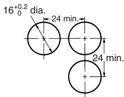
text_image
16⁺⁰·² dia. 24 min. 24 min.Rectangular
A165K□-2S
(Top View)
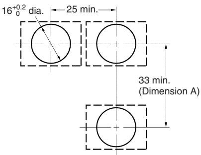
text_image
16⁺⁰·² dia. 25 min. 33 min. (Dimension A)Recommended panel thickness: 0.5 to 3.2 mm
Note: 1. Ensure that the variation in the distance between the centers of neighboring mounting holes is less than ±0.1 mm.
2. Make sure the thickness of the mounting panel is 0.5 to 3.2 mm. If, however, a Switch Guard or Dust Cover is used, the thickness of the mounting panel must be 0.5 to 2 mm.
3. If the panel is to be finished with coating, etc., make sure that the panel meets the specified dimensions after coating.
Installation
For details on mounting the Switch to a panel, and mounting and dismounting the Switch, refer to installation details for the A16 Pushbutton Switch.
Panel Mounting
Refer to the Installation section for the A16.
■ Mounting and Replacing the Pushbutton
Refer to the Installation section for the A16.
■ Flange Rotation
A165 Key-type Selector Switch
Fix the Switch screw and rotate the flange in 45^ turns.
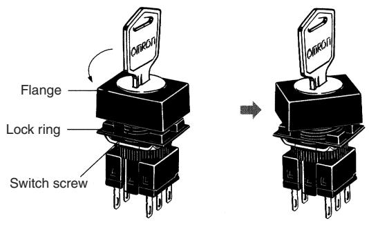
text_image
OTROU Flange Lock ring Switch screwPrecautions
Refer to the Technical Information for Pushbutton Switches (Cat. No. A143) and the Precautions section for the A16.
ALL DIMENSIONS SHOWN ARE IN MILLIMETERS.
To convert millimeters into inches, multiply by 0.03937. To convert grams into ounces, multiply by 0.03527.
Cat. No. A126-E1-02
In the interest of product improvement, specifications are subject to change without notice.