
LED3000 RL - Laser de nivellement LEICA - Notice d'utilisation et mode d'emploi gratuit
Retrouvez gratuitement la notice de l'appareil LED3000 RL LEICA au format PDF.

| Type de produit | Illuminateur LED annulaire (Ring Light) pour microscope stéréo |
| Marque | Leica Microsystems |
| Modèle | LED3000 RL |
| Nombre de LEDs | 24 |
| Diamètre extérieur | 70 mm (est.) |
| Hauteur | 30 mm (est.) |
| Poids | 200 g (est.) |
| Distance de travail supportée | 65 mm à 150 mm |
| Diamètre d'objectif compatible | 58 mm |
| Alimentation | Via colonne électronique (CTL2) ou adaptateur secteur externe (réf. 10 450 266) |
| Contrôle | Clavier intégré, Leica Application Suite (LAS), Leica SmartTouch® |
| Réglage de luminosité | 10 incréments |
| Scénarios d'éclairage | Anneau complet, demi-anneau, quart d'anneau, quarts opposés |
| Rotation des segments | Oui, via touches Ⓧ et ⭘ |
| Température de couleur | Constante (lumière du jour), env. 5500 K |
| Durée de vie des LEDs | Jusqu'à 50 000 heures |
| Entretien | Nettoyer avec un chiffon doux et sec. Ne pas utiliser de produits chimiques. |
| Sécurité | Allumer avant de regarder dans les oculaires. Ne pas regarder directement les LEDs. |
| Pièces détachées disponibles | Diffuseur optionnel, kit de polarisation, adaptateur secteur |
| Réparabilité | Réparation par techniciens Leica agréés uniquement, pièces d'origine |
| Utilisation en salle blanche | Oui |
FOIRE AUX QUESTIONS - LED3000 RL LEICA
Questions des utilisateurs sur LED3000 RL LEICA
0 question sur cet appareil. Repondez a celles que vous connaissez ou posez la votre.
Poser une nouvelle question sur cet appareil
Téléchargez la notice de votre Laser de nivellement au format PDF gratuitement ! Retrouvez votre notice LED3000 RL - LEICA et reprennez votre appareil électronique en main. Sur cette page sont publiés tous les documents nécessaires à l'utilisation de votre appareil LED3000 RL de la marque LEICA.
MODE D'EMPLOI LED3000 RL LEICA
natural_image
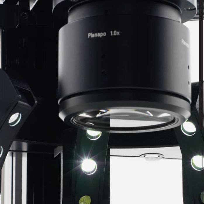
Close-up of a black optical lens system with visible components and green light reflections (no text or symbols)Leica LED Illuminator Manual
LED3000 RL
LED3000 NVI
LED5000 RL
LED5000 MCI
LED5000 CXI
LED5000 HDI™
General Instructions
Safety Concept
Before using your microscope for the first time, please read the "Safety concept" brochure included with your instrument. It contains additional information about handling and care.
Use in clean rooms

Leica LED illuminators can be used in clean rooms without any problems.
Cleaning
- Do not use any unsuitable cleaning agents, chemicals or techniques for cleaning.
- Never use chemicals to clean colored surfaces or accessories with rubberized parts. This could damage the surfaces, and specimens could be contaminated by abra-ded particles.
- In most cases, we can provide special solutions on request. Some products can be modified, and we can offer other accessories for use in clean rooms.
Servicing
- Repairs may only be carried out by Leica Microsystems-trained service technicians. Only original Leica Microsystems spare parts may be used.
Responsibilities of person in charge of instrument
- Ensure that the Leica LED illuminator is operated, maintained and repaired by authorized and trained personnel only.
Symbols Used
Warning of a danger
This symbol indicates especially important information that must be read and complied with. Failure to follow these instructions may pose hazards to personnel, impair the system's performance or damage the instrument.
Important information
This symbol indicates additional information or explanations that intend to provide clarity.
Explanatory notes
- This symbol within the text stands for additional information and explanations.
Table of Contents
About Leica LED Illuminators
LED: Illuminant with a Future 6
Control via LAS and Leica SmartTouch ^® 7
Leica LED3000 RL
About the Leica LED3000 RL 9
Leica LED3000 RL: Assembly 10
Leica LED3000 RL: Use 12
Control of the Leica LED5000 3000 Ring Illuminator 13
Leica LED3000 RL: Dimensional Drawings 14
Leica LED3000 NVI™
About the Leica LED3000 NVI ^TM 16
Leica LED3000 NVI ^™ : Assembly 17
Leica LED3000 NVI ^TM : Use 19
Leica LED3000 NVI ^™ and Leica SmartTouch ^® 20
Leica LED3000 NVI™: Dimensional Drawings 21
Leica LED5000 RL
About the Leica LED5000 RL 23
Leica LED5000 RL: Assembly 24
Leica LED5000 RL: Use 25
Leica LED5000 RL and Leica SmartTouch ^® 26
Leica LED5000 RL: Dimensional Drawings 27
Leica LED5000 MCI
About the Leica LED5000 MCI 29
Leica LED5000 MCI: Assembly 30
Leica LED5000 MCI: Alternative Assembly 31
Leica LED5000 MCI ^™ : Use 32
Leica LED5000 MCI and Leica SmartTouch ^® 34
Leica LED5000 MCI: Dimensional Drawings 35
Leica LED5000 CXI
About the Leica LED5000 CXI 37
Leica LED5000 CXI: Assembly 38
Leica LED5000 CXI: Use 40
Leica LED5000 CXI and Leica SmartTouch ^® 41
Leica LED5000 CXI: Dimensional Drawings 42
Leica LED5000 HDI™
About the Leica LED5000 HDI ^™ 44
Leica LED5000 HDI ^™ : Assembly 45
Leica LED5000 HDI ^™ : Illumination Scenarios 46
Leica LED5000 HDI ^™ and Leica SmartTouch ^® 48
Leica LED5000 HDI ^™ : Dimensional Drawings 49
About Leica LED Illuminators
LED: Illuminant with a Future
Congratulations on purchasing your LED illuminator from Leica Microsystems. You have made an excellent choice: You will enjoy the high quality and well-conceived operation for a long time to come and it will provide the best possible lighting for your work – regardless of the type of specimen you would like to examine.
All of the Leica LED illuminators offer a great number of advantages you will not want to do without:
- Constant color temperature (daylight) throughout the entire lifecycle
- Extremely long service life of up to 50,000 hours
-
Absolutely maintenance-free; no lamp replacement required
-
Depending on the illuminator, individual segments can be switched on or off independently from one another so that different illumination scenarios are possible.
- It is controlled either on the instrument, via the Leica SmartTouch® panel or via the Leica Application Suite software
- Extremely low power consumption at high light efficiency
The Leica LED illuminators work seamlessly with all Leica M series stereomicroscopes.
Using the Leica Application Suite software (LAS), users can control, save, and later call up scenarios with different microscope and light settings at the touch of a button.
We wish you great joy and success with your new LED illuminator by Leica Microsystems!
Control via LAS and Leica SmartTouch®
Each Leica LED illuminator can also be controlled via the Leica Application Suite (LAS) or the Leica SmartTouch ^® control unit.
Leica Application Suite (LAS)
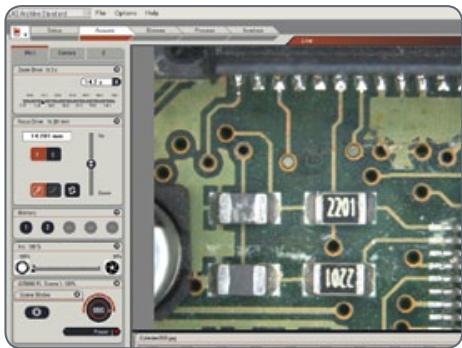
The PC-based LAS software allows users to integrate each Leica LED illuminator into the workflow. Control the intensity of the illumination and the desired illumination scenario from your computer. Stored scenarios can be called up at any time at the touch of a button so that you
can be assured that you will have consistent conditions for your experiments.
For information on how to control the LED illuminator via LAS, refer to the user manual for the LAS software.
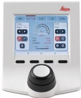
Leica SmartTouch®
All Leica LED illuminators can also be used with the Leica SmartTouch® control unit. Exactly as is the case with LAS, the illuminator can be switched on and off or the brightness can be adjusted. Moreover, you can access one of the preset illumination scenarios with a single tap. All settings can be saved and retrieved later at the touch of a button.
The instructions for controlling the illuminator using Leica SmartTouch ^® can be found in this User Manual.
Leica SmartTouch™
Leica LED3000 RL
About the Leica LED3000 RL
The Leica LED3000 RL ("Ring Light") generates a very bright and homogenous incident light. The ring illuminator illuminates the specimen with 24 LEDs that can be switched on or off together or in various combinations.

The Leica LED 3000 RL can be used with any objectives that have an outer diameter of 58 mm. The supported working distance is between 65 mm and 150 mm.
Controls
It is controlled using either the integrated keypad or via the Leica Application Suite (LAS) or the Leica SmartTouch ^® .
LAS and the Leica SmartTouch ^® enable you to create fully reproducible illumination scenarios and automatically toggle between them. For additional information on controlling the illuminator via LAS, please refer to the LAS online help.
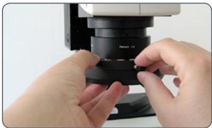
Leica LED3000 RL: Assembly
Required tools
None
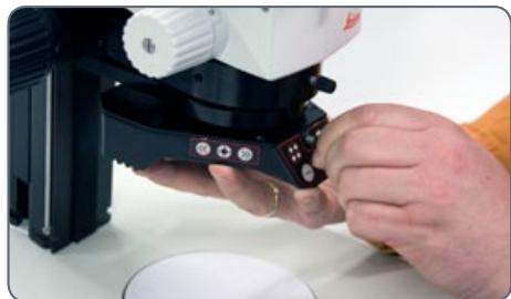
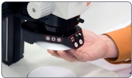
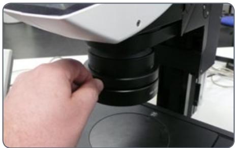
Installing the Leica LED3000 RL
- Place the Leica LED3000 RL on the objective from below and tighten the locking screw.
natural_image
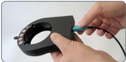
Close-up of hands operating a microscope with a small display on the handle (no visible text or symbols)Connection and power supply
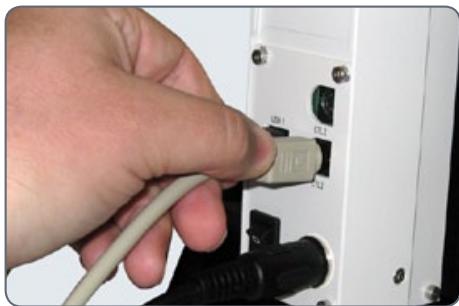
The Leica LED3000 RL can be used directly with the electronic focusing column. The power is then supplied via the CTL2 connection. In addition, the communication between LAS or the Leica SmartTouch® is transferred via the same connection.
If you work with the manual focusing column, the Leica LED3000 RL must be supplied with power via the external power supply unit provided. Moreover, the illuminator cannot be controlled via the Leica Application Suite in this case.
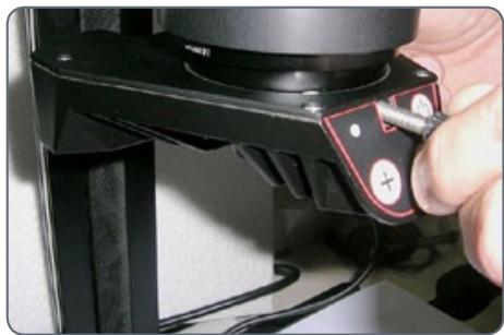
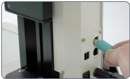
Connection to the electronic focusing column
- Connect the Leica LED3000 RL to the focusing column via the CTL2 port.

natural_image
Close-up of a hand inserting a USB into a device panel (no visible text or symbols)Leica LED3000 RL: Assembly (cont'd.)
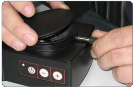
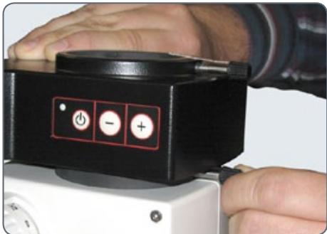
Power supply when using the manual focusing column
- Connect the external power supply unit (10 450 266) to the Leica LED3000 RL.
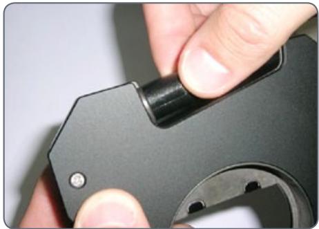
Installing optional accessories
- The optional diffuser is attached and screwed in below the ring illuminator.
natural_image
Close-up of a hand holding a white and black scientific instrument with control buttons (no visible text or symbols)- The optional polarization set (polarizer and analyzer) is attached and screwed in below the ring illuminator.
Leica LED3000 RL: Use

The light of the Leica LED3000 RL can be very bright. Therefore, always switch on the illuminator before you look through the eyepieces! Avoid looking directly into the LEDs.
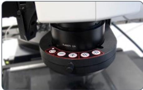
Using the keypad
- Use the ⏻ button to switch the Leica LED3000 RL illuminator on or off.
- Use the ⊕ and ⊖ buttons to adjust the brightness in 10 increments.
- Touch either of the two buttons to adjust the quantity of light in small increments.
- Hold the button pressed to change the quantity of light more quickly.
The illumination scenarios
You can switch between different illumination scenarios (full ring, half ring, quarter rings, opposite quarter rings) using the button. The active illuminator segments are displayed on the front control panel field by means of LEDs.
Use the Ⓧ and ⭘ buttons to rotate the active segments clockwise or counterclockwise.
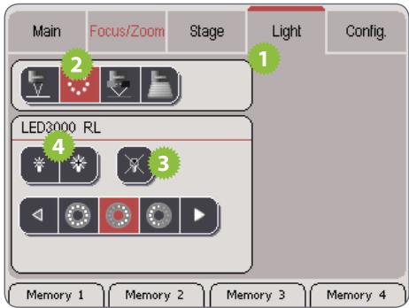
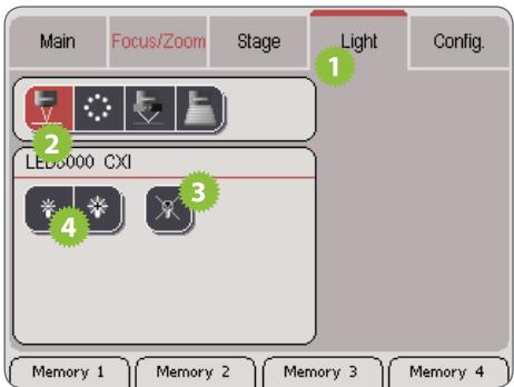
Control of the Leica LED5000 3000 Ring Illuminator
Using the Leica SmartTouch™, you can control both the brightness and various illumination scenarios for the Leica LED3000 RL ("Ring Light").
Adjusting the illumination

- Touch the "Light" tab.
- In the upper area, touch the symbol for the Leica LED3000 RL.
-
Switch on the illuminator.
-
Touch the lamp symbols to adjust the intensity of the light.
- Touch one of the symbols for the light scenarios to adjust the lighting to your needs.

natural_image
User interface button with playback, refresh, and play icons (no text or symbols)
You cannot modify the default illumination scenarios.
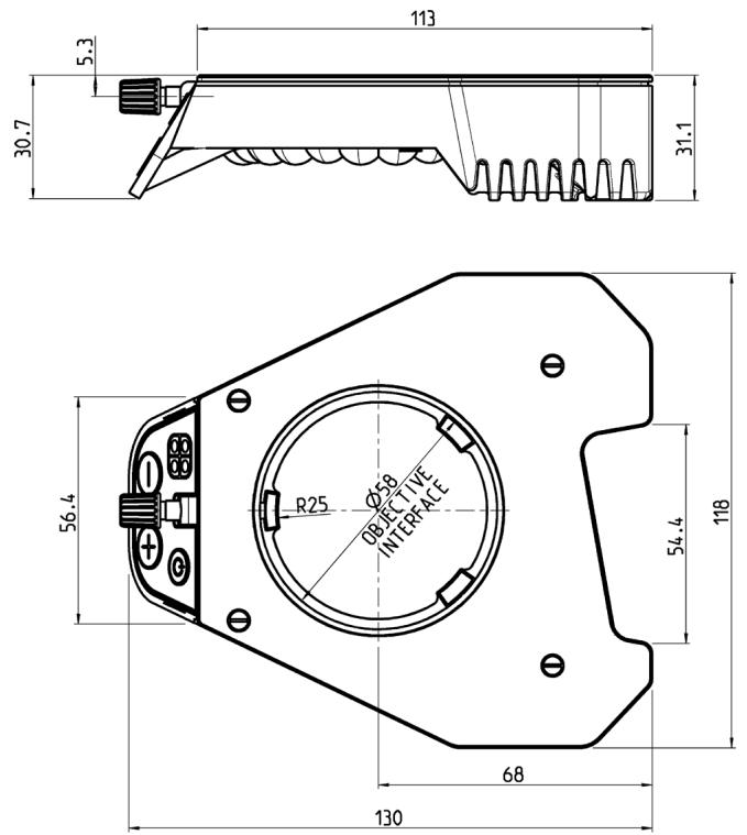
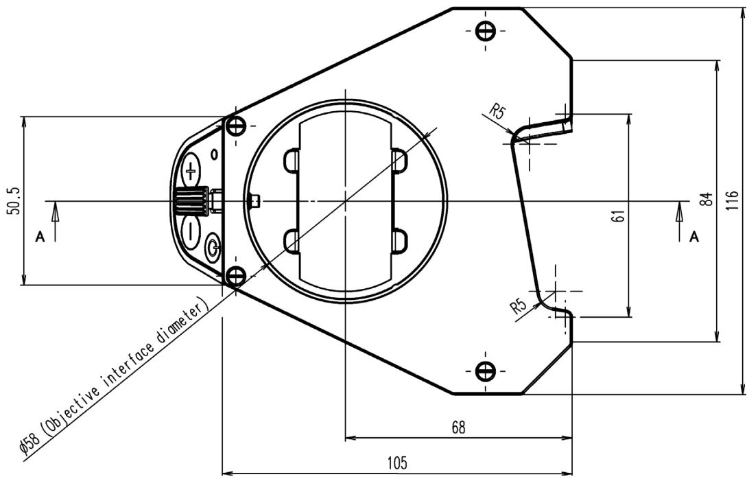
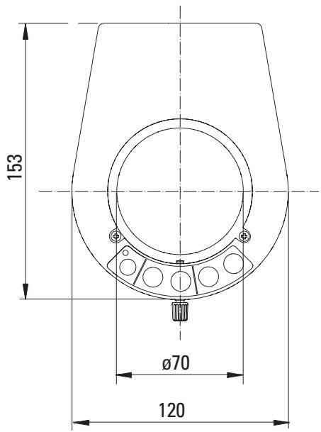
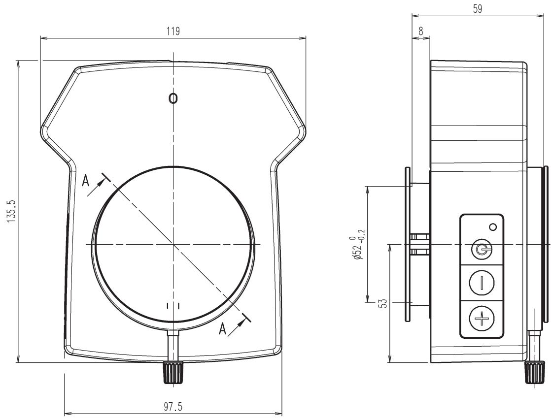
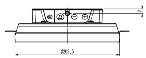
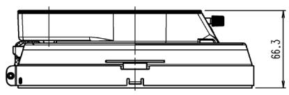
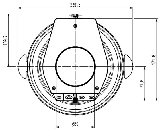
Leica LED3000 RL: Dimensional Drawings
Leica LED3000 RL (dimensions in mm)
Leica LED3000 NVI™
About the Leica LED3000 NVI™
Leica LED3000 NVI™ –
The vertical LED light solution
Unlike coaxial illumination, the LED3000 NVI ^™ also works for uneven specimens and specimens that have weak reflection. It is ideally suited for viewing recesses and bores and attains a substantially brighter illumination than comparable 150 watt halogen lamps. Minimized shadows caused by tools also contribute to an easier and more pleasing work experience with the microscope.
Leica LED3000 NVI™: Assembly
Required tools
None

The Leica LED 3000 NVI ^™ can be used with any objectives that have an outer meter of 58 mm.

The supported working distance is between 50 mm and 150 mm.
Installing the Leica LED3000 NVI™
- Connect the Leica LED3000 NVITM to the focusing column via the CTL2 connection if the focusing column is equipped with integrated electronics.
natural_image
Close-up of a hand holding a black plastic mechanical component with a circular hole (no text or symbols visible)Alternative installation for manual columns
- Connect the external power supply unit (10 450 266) to the Leica LED3000 NVI™.
- Place the Leica LED3000 NVI™ on the optics carrier from below and tighten the locking screw.
natural_image
Close-up of a hand using a screwdriver to adjust a black mechanical component (no visible text or symbols)Leica LED3000 NVI™: Assembly (cont'd.)
Ensure that the locking screw of the illuminator and the locking screw of the optics carrier are on a straight line, as otherwise image shading may occur.
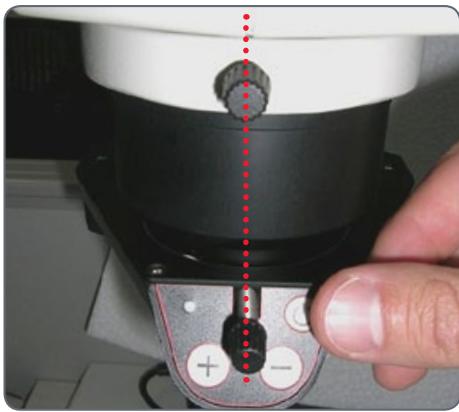
natural_image
Close-up of a hand operating a camera lens with a red dotted line indicating alignment (no text or symbols visible)Leica LED3000 NVI™: Use
The intensity of the illuminator can be adjusted in 10 increments.
The Leica LED3000 NVI™ can also be controlled via the Leica Application Suite (LAS) or the Leica SmartTouch.
The supported working distance is between 50 mm and 150 mm.
When pressing the buttons, hold the keypad between your thumb and index finger. Avoid tapping the keypad with just one finger if possible.
Use
The light of the Leica LED3000 NVI™ can be very bright. Therefore, always switch on the illuminator before you look through the eyepieces!
- Switch on the illuminator by briefly pressing the ⬇ (ON/OFF) button.
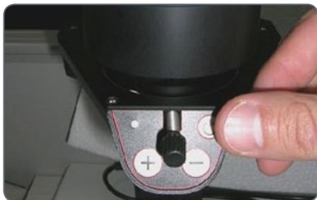
natural_image
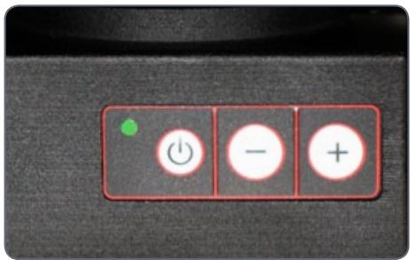
Close-up of a hand operating a mechanical device with a knob and adjustment knobs (no visible text or symbols)The green LED on the upper left corner now lights up.
- Adjust the brightness by briefly pressing the or buttons.
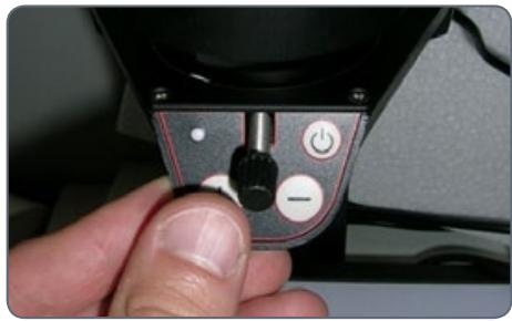
natural_image
Close-up of a hand holding a camera lens with adjustment knobs and a power button (no text or symbols visible)- Switch off the illuminator by briefly pressing the ⬆ button.
Leica LED3000 NVI™ and Leica SmartTouch®
Adjusting the illumination
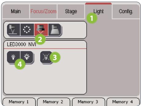
- Touch the "Light" tab.
- In the upper area, touch the symbol of the Leica LED3000 NVI.
- Switch on the illuminator.
- Touch the lamp symbols to adjust the intensity of the light.
Leica LED3000 NVI™: Dimensional Drawings
Leica LED3000 NVI™ (dimensions in mm)
Leica LED5000 RL
About the Leica LED5000 RL
Use
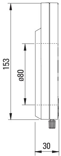
The Leica LED5000 RL ("Ring Light") generates a very bright and homogenous incident light. It has a diameter of 80 mm and illuminates the specimen with 48 LEDs that can be switched on and off completely or in various combinations. It is controlled using either the integrated keypad or via the Leica Application Suite (LAS).
LAS enables you to create fully reproducible illumination scenarios and automatically toggle between them. For additional information, refer to the LAS online help.
flowchart
graph LR
    A[" "] --> B[" "]
    B --> C[" "]
    C --> D[" "]
    D --> E[" "]
    E --> F[" "]
Leica LED5000 RL: Assembly
The ring illuminator, the Leica LED5000 RL ("Ring Light"), is installed on the objective using a single screw. It has been optimized for a working distance between 60 and 70 mm.

natural_image
Close-up of a black circular mechanical component with a red control knob and buttons (no visible text or symbols)Constraints
The Leica LED5000 RL can be used in conjunction with the planapochromat 1× and planapochromat 0.63× objectives. With all other objectives, the working distance is too low for adequate illumination.
The ring illuminator cannot be used together with the objective nosepiece.
Assembly
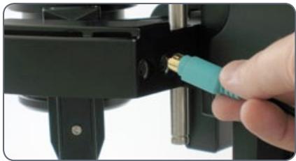
- Connect the CAN-bus cable to the ring illuminator. The flat part of the plug must be facing upwards.
natural_image
Close-up of hands holding a black mechanical clamp with a teal tool inserted, no visible text or symbols- Push the ring illuminator over the objective as far as it will go and screw it into place.
natural_image
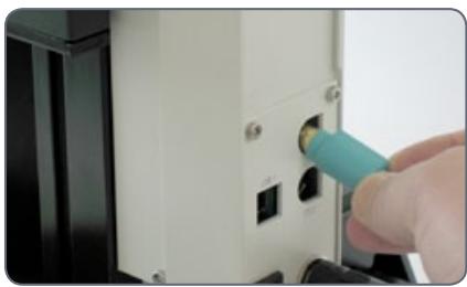
Close-up of hands adjusting a black mechanical component with a white connector (no visible text or symbols)- Plug the other end of the cable into one of the two "CTL2" sockets on the column.
natural_image
Close-up of a hand inserting a small electronic component into a device (no visible text or symbols)For optimum accessibility of the specimen, the ring illuminator should be installed with the cable facing backwards. However, it is also possible to turn the ring illuminator sideways, for example if simultaneously using the Leica LED5000 MCI ^™ system illumination. In this case, the ring illuminator cannot be connected directly to the Leica LED5000 MCI ^™ .
Leica LED5000 RL: Use

The light of the Leica LED5000 RL can be very bright. Therefore, always switch on the illuminator before you look through the eyepieces! Avoid looking directly into the LEDs.
Using the keypad
natural_image
Close-up of a robotic arm with a black head and red control buttons (no visible text or symbols)- Use the ⏻ button to switch the illumination on or off.
- Use the ⊕ or ⊖ buttons to adjust the brightness in 10 increments. Touch either of the two buttons to adjust the intensity in small increments. Hold a key to change the intensity more quickly.
The illumination scenarios
Use the Ⓧ and ⭘ buttons to toggle between the various illumination scenarios.
Constraint
The Leica LED5000 RL has been designed for use with the 1.0× and 0.63× objectives. For the 1.6× and 2.0× objectives, conventional ring illuminators from the Leica illuminator product range are available.
Leica LED5000 RL and Leica SmartTouch®

Using the Leica SmartTouch™, you can control both the brightness and various nation scenarios for the Leica LED3000 RL (Light").
Adjusting the illumination
- Touch the "Light" tab.
- In the upper area, touch the symbol for the Leica LED3000 RL.
-
Switch on the illuminator.
-
Touch the lamp symbols to adjust the intensity of the light.
- Touch one of the symbols for the light scenarios to adjust the lighting to your needs.

natural_image
User interface button with playback, refresh, and play icons (no text or symbols)
You cannot modify the default illumination scenarios.
Leica LED5000 RL: Dimensional Drawings
Leica LED5000 RL (dimensions in mm)
Leica LED5000 MCI
About the Leica LED5000 MCI
Leica LED5000 MCI™ –
The expert for oblique illumination
The Leica LED5000 MCI ^™ (Multi Contrast Illumination) is a one-of-a-kind lighting solution for applications in which, until now, goose-neck illuminators had been used. The flat angle of the oblique incident light creates a particularly high contrast for viewing the specimen, allowing the user to detect minute unevenness and faults, e.g. scratches and dust particles. In contrast to the goose-neck illuminator, the settings of the LED5000 MCI ^™ are fully reproducible.
Advantages
- Nine high-performance LEDs from different angles and directions
- High contrast allows users to discover fine structures on the specimen
- Illumination angle of 15 – 40°
• Reproducible illumination settings
• Optimum access to specimen

Of course, the Leica LED5000 MCI ^™ can also be controlled by the LAS (Leica Application Suite) software.
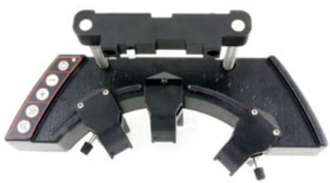
Leica LED5000 MCI: Assembly
The Leica LED5000 MCI™ (for "Multi Contrast Illumination") is installed using two screws. For optimum accessibility, the optics carrier should be removed during installation.
natural_image
Mechanical clamp device with black components and mounting bracket (no visible text or symbols)Constraints
The Leica LED5000 MCI ^™ cannot be used together with the objective nosepiece.
Assembly
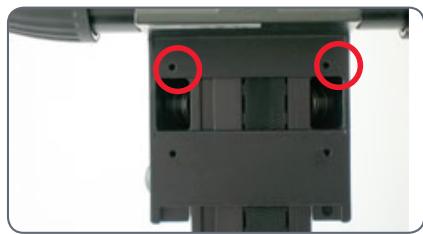
- Hold the LED5000 MCI ^™ with one hand and tightly screw the retraining stirrups on both top holes on the drive housing.
natural_image
Close-up of a mechanical component with two red-circled features, no visible text or symbols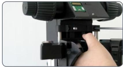
natural_image
Close-up of a hand adjusting a camera lens component (no visible text or symbols)- Connect the CAN-bus cable to either of the two sockets. (The flat part of the plug must be facing downwards.)
natural_image
Close-up of a hand inserting a gold-colored USB into a mechanical component (no visible text or symbols)- Plug the other end of the cable into one of the two "CTL2" sockets on the column.
natural_image
Close-up of a hand inserting a small electronic component into a white electronic device (no visible text or symbols)Leica LED5000 MCI: Alternative Assembly
Under certain circumstances, the light source must not be moved along with the optics carrier. A typical example is multifocus images in which the Z-stack changes while the angle of incidence of the light must remain the same. For such purposes, the Leica LED5000 MCI ^™ is directly fastened to the column.
Installation on the column
- Pull the retaining stirrup out of the Leica LED5000 MCI ^™ .
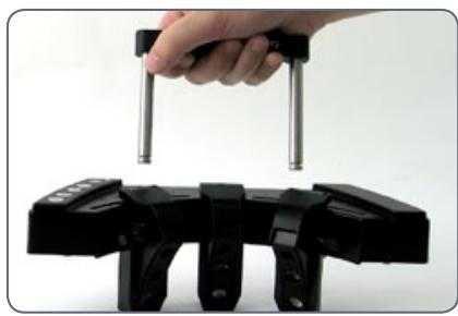
natural_image
Hand holding a metal clamp above a black mechanical clamp (no text or symbols visible)If using the AX carrier, use the upper engaging position of the retaining stirrup.
- Screw the retaining stirrup into the column at the notch using the single screw. If you tighten the screw, the retaining stirrup is automatically moved into the correct position.

natural_image
Close-up of a 3D printer with a screwdriver inserted, showing mechanical components and no visible text or symbols.- Push the Leica LED5000 MCI ^™ onto the retaining stirrup.
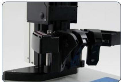
natural_image
Close-up of a black mechanical device with a lever mechanism (no visible text or symbols)Leica LED5000 MCI™: Use
Use
The Leica LED5000 MCI ^™ (for "Multi Contrast Illumination") is a universal high-output illuminator. Three groups of 3 LEDs each can be arranged as desired around the specimen. The targeted control of the LEDs enables various illumination scenarios to be implemented.
Preparation
Hold the MCI with both hands and pull it downwards until the illuminator clicks into place on the bottom end of the guide rods.
In this position, you always have the same contrast with identical illumination. This guarantees the reproducibility of an experiment.
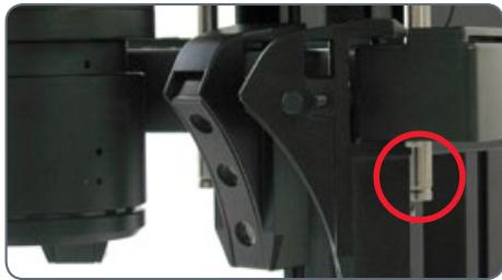
natural_image
Close-up of mechanical components with a red circle highlighting a small component (no visible text or symbols)Installed too high
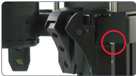
natural_image
Close-up of mechanical components with a red circle highlighting a small component (no visible text or symbols)Optimum height
Contact with the base
If the optics carriers are accidentally lowered too far, contact between the base and MCI may result. A safety mechanism in the linkage ensures that in this case, the MCI is automatically pushed upwards to prevent the possibility of damage.
- Be sure not to place any specimens directly beneath the MCI.
- After the optics carrier is lifted, put the MCI back into the original position.
Leica LED5000 MCI™: Use (cont'd.)
Using the keyboard
- Use the ⏻ key to switch the illumination on or off.
- Use the "+" and "-" keys to adjust the brightness in 10 increments. Touch either of the two buttons to adjust the intensity in small increments. Hold a key to change the intensity more quickly.
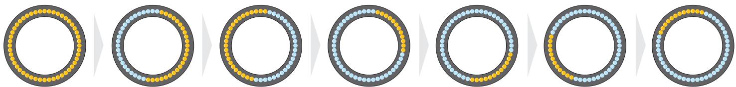
The illumination scenarios
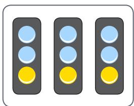
Use the "«" and "»" keys to toggle between the illumination scenarios shown below.
Maximum brightness
For temperature reasons its is not possible to switch on all nine LEDs simultaneously. Therefore, to provide bright overall illumination, the top two rows are activated. The bottom row primarily provides contrast.
The Leica LED5000 MCI ^™ can also be controlled by the LAS (Leica Application Suite) software.
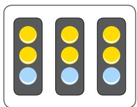
natural_image
Three identical traffic lights with yellow and blue dots, arranged horizontally (no text or symbols)Maximum brightness
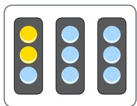
natural_image
Three identical traffic lights with blue and yellow dots, arranged horizontally (no text or symbols)Maximum contrast

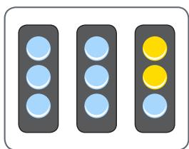
natural_image
Three identical traffic lights with blue and yellow lights, arranged horizontally (no text or symbols)Point illumination from the rear
natural_image
Three traffic lights with yellow and blue dots, arranged horizontally (no text or symbols)Point illumination from the left
natural_image
Three identical traffic lights with blue and yellow dots, arranged horizontally (no text or symbols)Point illumination from the right
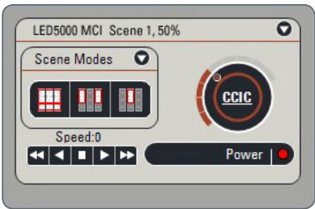
Leica LED5000 MCI and Leica SmartTouch®
Using the Leica SmartTouch™, you can control both the brightness and various illumination scenarios for the Leica LED5000 MCI ("Multi Contrast Illumination").
Adjusting the illumination
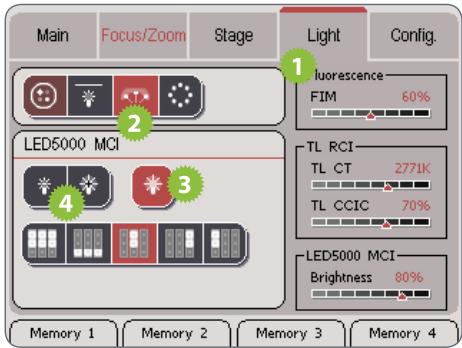
- Touch the "Light" tab.
- In the upper area, touch the symbol for the Leica LED5000 MCI.
- Switch on the illuminator.
- Touch the lamp symbols to adjust the intensity of the light.

The selected brightness is shown on the right side of the display.
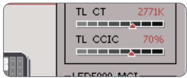
- Touch one of the symbols for the light scenarios to adjust the lighting to your needs.

natural_image
Pure electrical circuit lines without any symbols
You cannot modify the default illumination scenarios.
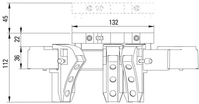
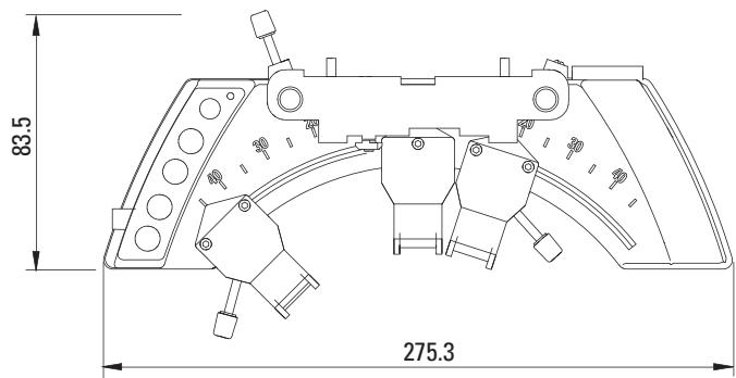
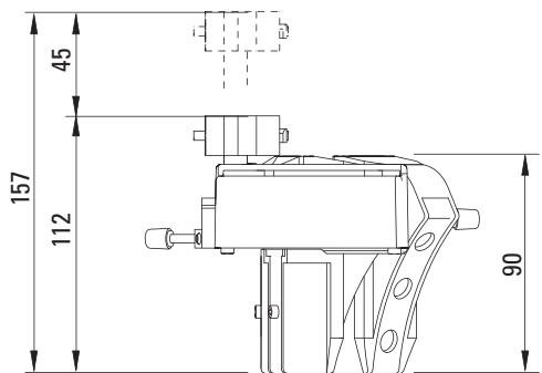
Leica LED5000 MCI: Dimensional Drawings
Leica LED5000 MCI (dimensions in mm)
Leica LED5000 CXI
About the Leica LED5000 CXI
Leica LED5000 CXI™ –
The coaxial LED light solution
The Leica LED5000 CXI ^™ is a coaxial illuminator that combines the benefits of LED technology within the smallest space: long service life, bright illumination in natural light quality, plus integration into the Leica LAS software and fully reproducible illumination settings.
The Leica LED5000 CXI ^™ is ideally suited for illuminating flat, reflective or polished specimens. It offers substantially brighter illumination than comparable 150 watt halogen lamps.
Use with the microscope carrier AX
If the microscope carrier AX is used in the vertical position, a quarter-wave plate is necessary:
- Fasten the quarter-wave plate to the objective using the clamping screw.
natural_image
Close-up of a hand using a microscope to observe a black-and-white lens (no text or symbols visible)- Rotate the quarter-wave plate upwards using the knurled ring until the desired effect is attained.
Use with the Leica M205 C / M205 A stereomicroscope
If the Leica LED5000 CXI illuminator is used with the Leica M205 C or Leica M205 A, bear in mind that an AX microscope carrier is used. The carrier must be in position (M205) during assembly.
In order to achieve uniform illumination in "stereo viewing", the AX carrier must be moved to the right as far as it will go. This position deviates from the default stereo position by 2 mm.
Leica LED5000 CXI: Assembly
Required tools
None
Installing the Leica LED5000 CXI
- Connect the Leica LED5000 CXI to the focusing column via the CTL2 connection if the focusing column is equipped with integrated electronics.
natural_image
Close-up of a hand inserting a USB cable into a white electronic device (no visible text or symbols)Alternative installation for manual columns
-
Connect the external power supply unit (10 450 266) to the Leica LED5000 CXI.
-
Unscrew the positioning screw and remove the protective cover.
natural_image
Close-up of hands using a handheld device to press or install a black circular component, with control buttons visible (no text or symbols)Leica LED5000 CXI (continued)
-
Place the Leica LED5000 CXI on the optics carrier and tighten the positioning screw.
-
Push the tube (for example, the inclined binocular tube) into the dovetail ring and rotate it slightly in both directions until the positioning screw meshes with the guide groove.
-
While holding the tube only slightly, carefully tighten the positioning screw. It is automatically brought to the correct position.
natural_image
Close-up of hands operating a black electronic device with three buttons (positive, negative, and +) on its side, no visible text or symbols.
natural_image
Person using a handheld device with a white tip and black handle, showing control buttons (no visible text or symbols)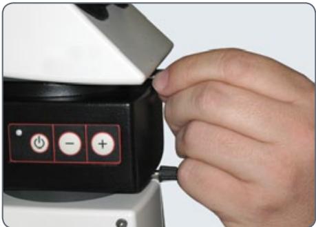
natural_image
Close-up of a hand inserting a button into a device, showing power and charge symbols (no text or labels visible)Leica LED5000 CXI: Use
The intensity of the illuminator can be adjusted in 10 increments.
The Leica LED3000 NVI™ can also be controlled via the Leica Application Suite (LAS) or the Leica SmartTouch.
Using the Leica LED5000 CXI results in an increased magnification level of 1.5×.
Depending on the components used, different intensities of vignetting may occur at low magnification. Vignetting is normal and not a malfunction.
Use
The light of the Leica LED5000 CXI can be very bright. Therefore, always switch on the illuminator before you look through the eyepieces!
- Switch on the illuminator by briefly pressing the ⬇ (ON/OFF) button.
The green LED on the upper left corner now lights up.
- Adjust the brightness by briefly pressing the or buttons.
- Switch off the illuminator by briefly pressing the ⬆ button.
Leica LED5000 CXI and Leica SmartTouch®
Adjusting the illumination
- Touch the "Light" tab.
- In the upper area, touch the symbol of the Leica LED5000 CXI.
- Switch on the illuminator.
- Touch the lamp symbols to adjust the intensity of the light.
Leica LED5000 CXI: Dimensional Drawings
Leica LED5000 CXI (dimensions in mm)
Leica LED5000 HDI™
About the Leica LED5000 HDI™
The Leica LED5000 HDI™ (for "High Diffuse Illumination") is a newly-designed, innovative high-output illuminator. Its soft light reduces reflection on highly reflective specimens and prevents stray light.
The Leica LED5000 HDI ^™ consists of a flexible plastic dome. It houses two independent LED rings that can be controlled individually.
It is controlled using either the integrated keypad or via the Leica Application Suite (LAS) or the Leica SmartTouch ^® .
The Leica LED5000 HDI ^™ is installed on the objective using a single screw. The working distance has been optimized for a height between 60 and 70 mm.
Constraints
The Leica LED5000 HDI ^™ can only be used with objectives that have an outer diameter of 80 mm.
The Leica LED5000 HDI ^™ has been optimized for the planapochromat 1× and planapochromat 0.63×.
Control via Leica Application Suite
The Leica LED5000 HDI™ illuminator will be supported by LAS version 3.6 and higher (Summer 2010).
LAS enables you to create fully reproducible illumination scenarios and automatically toggle between them. For additional information, refer to the LAS online help.
Leica LED5000 HDI™: Assembly
Connection
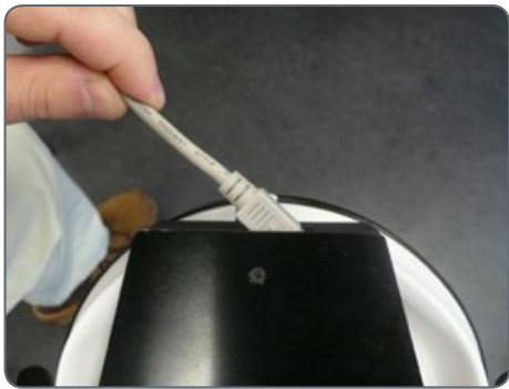
- Connect the CAN-bus cable to the illuminator. The flat part of the plug must be facing upwards.
natural_image
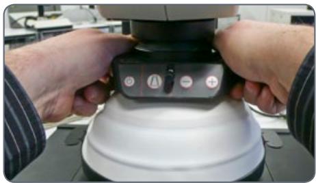
Hand using a brush to apply black powder on a white plate (no text or symbols visible)- In an in-focus state, slide the illuminator over the objective until it can no longer touch the baseplate when folded down and screw it into place. When doing so, the control panel field should be facing the user.
natural_image
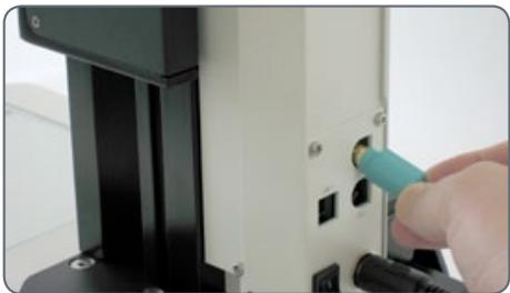
Close-up of hands operating a mechanical device with a control panel (no visible text or symbols)- Plug the other end of the cable into one of the two "CTL2" sockets on the rear side of the focusing column.
natural_image
Close-up of a hand inserting a cable into a device panel (no visible text or symbols)Depending on the height of the specimen to be examined, the LED5000 HDI™ can be installed a bit higher or lower along the objective.
Leica LED5000 HDI™: Illumination Scenarios
Using the keypad
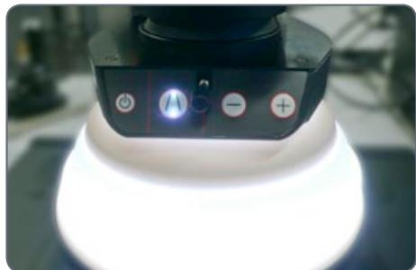
- Use the ⏻ button to switch the illumination on or off.
natural_image
Close-up of a robotic device with illuminated control buttons and a glowing base (no visible text or symbols)- Use the 📁 button to switch between the three illumination modes: Both LED rings active > Top LED ring active > Bottom LED ring active
- If both LED rings are active, only the brightness of the top ring can be changed. Depending on the specimen and requirements, it is thus possible to attain balanced brightness conditions for both rings.
- Use the ⊕ or ⊖ buttons to adjust the brightness in 10 increments. Touch either of the two buttons to adjust the intensity in small increments. Hold the button pressed to change the intensity more quickly.
The illumination scenarios
The flexible plastic dome is the central feature of the Leica LED5000 HDI™. It allows two illuminator operating modes.
You can switch between the two modes by moving the dome upwards or downwards at the two tabs on the left and right of the metal ring.
Thanks to the high flexibility, it is also possible to just fold up or down one side.
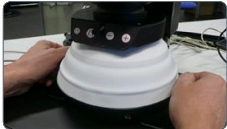
natural_image
Close-up of hands operating a mechanical device with a white dome-like component on a black surface (no visible text or symbols)Leica LED5000 HDI™: Illumination Scenarios (continued)
The use of flexible plastic eliminates "hard collisions" with specimens to a large extent. For very sensitive specimens, however, even the weight of the illuminator itself can cause damage.
1. Dome folded down
In this mode, the Leica LED5000 HDI ^™ is particularly powerful. Homogeneity is at the highest level and the stray light from outside is blocked.
2. Dome folded up
This mode allows continued access to the specimen for additional setup. This mode also ensures illumination with minimal reflections.
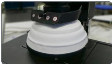
natural_image
Close-up of a white 3D-printed mechanical device with black components and control buttons (no visible text or symbols)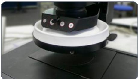
natural_image
Close-up of a mechanical device with a circular base and black components on a black base (no visible text or symbols)Leica LED5000 HDI™ and Leica SmartTouch®
Using the Leica SmartTouch™, you can control both the brightness and the various illumination scenarios for the Leica LED5000 RL ("Ring Light").
Adjusting the illumination
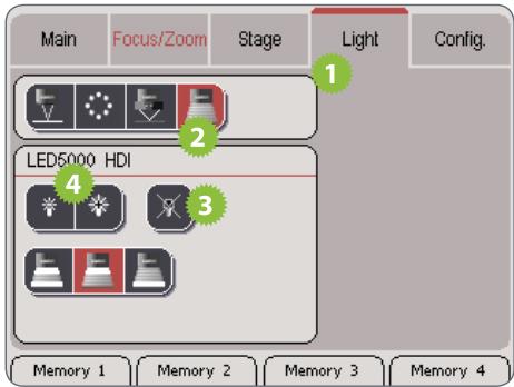
- Touch the "Light" tab.
-
In the upper area, touch the symbol for the Leica LED5000 HDI.
-
Switch on the illuminator.
- Touch the lamp symbols to adjust the intensity of the light.
- Touch one of the symbols for the light settings to adjust the lighting to your needs.

Leica LED5000 HDI™: Dimensional Drawings
Leica LED5000 HDI™ (dimensions in mm)
Folded Dome
natural_image
Technical line drawing of a mechanical component with dimension标注 (no text or symbols)Unfolded dome

- Leica LED Illuminator Manual
- General Instructions
- Safety Concept
- Cleaning
- Servicing
- Responsibilities of person in charge of instrument
- Symbols Used
- Warning of a danger
- Important information
- Explanatory notes
- Table of Contents
- About Leica LED Illuminators
- Leica LED3000 RL
- Leica LED3000 NVI™
- Leica LED5000 RL
- Leica LED5000 MCI
- Leica LED5000 CXI
- Leica LED5000 HDI™
- LED: Illuminant with a Future
- Control via LAS and Leica SmartTouch®
- Leica SmartTouch®
- About the Leica LED3000 RL
- Controls
- Leica LED3000 RL: Assembly
- Required tools
- Installing the Leica LED3000 RL
- Connection and power supply
- Connection to the electronic focusing column
- Leica LED3000 RL: Assembly (cont'd.)
- Power supply when using the manual focusing column
- Installing optional accessories
- Leica LED3000 RL: Use
- Using the keypad
- The illumination scenarios
- Control of the Leica LED5000 3000 Ring Illuminator
- Leica LED3000 RL: Dimensional Drawings
- About the Leica LED3000 NVI™
- The vertical LED light solution
- Leica LED3000 NVI™: Assembly
- Installing the Leica LED3000 NVI™
- Alternative installation for manual columns
- Leica LED3000 NVI™: Assembly (cont'd.)
- Leica LED3000 NVI™: Use
- Leica LED3000 NVI™ and Leica SmartTouch®
- Leica LED3000 NVI™: Dimensional Drawings
- About the Leica LED5000 RL
- Use
- Leica LED5000 RL: Assembly
- Constraints
- Assembly
- Leica LED5000 RL: Use
- Constraint
- Leica LED5000 RL and Leica SmartTouch®
- Leica LED5000 RL: Dimensional Drawings
- About the Leica LED5000 MCI
- Leica LED5000 MCI™ –
- The expert for oblique illumination
- Advantages
- Leica LED5000 MCI: Assembly
- Leica LED5000 MCI: Alternative Assembly
- Installation on the column
- Leica LED5000 MCI™: Use
- Preparation
- Contact with the base
- Leica LED5000 MCI™: Use (cont'd.)
- Using the keyboard
- Maximum brightness
- Leica LED5000 MCI and Leica SmartTouch®
- Leica LED5000 MCI: Dimensional Drawings
- About the Leica LED5000 CXI
- Leica LED5000 CXI™ –
- The coaxial LED light solution
- Use with the microscope carrier AX
- Use with the Leica M205 C / M205 A stereomicroscope
- Leica LED5000 CXI: Assembly
- Installing the Leica LED5000 CXI
- Leica LED5000 CXI (continued)
- Leica LED5000 CXI: Use
- Leica LED5000 CXI and Leica SmartTouch®
- Leica LED5000 CXI: Dimensional Drawings
- About the Leica LED5000 HDI™
- Control via Leica Application Suite
- Leica LED5000 HDI™: Assembly
- Connection
- Leica LED5000 HDI™: Illumination Scenarios
- Leica LED5000 HDI™: Illumination Scenarios (continued)
- Dome folded down
- Dome folded up
- Leica LED5000 HDI™ and Leica SmartTouch®
- Leica LED5000 HDI™: Dimensional Drawings
Marque : LEICA
Modèle : LED3000 RL
Catégorie : Laser de nivellement