Delta 8000 TAP RF - Thermostat DELTA DORE - Notice d'utilisation et mode d'emploi gratuit
Retrouvez gratuitement la notice de l'appareil Delta 8000 TAP RF DELTA DORE au format PDF.


Questions des utilisateurs sur Delta 8000 TAP RF DELTA DORE
0 question sur cet appareil. Repondez a celles que vous connaissez ou posez la votre.
Poser une nouvelle question sur cet appareil
Téléchargez la notice de votre Thermostat au format PDF gratuitement ! Retrouvez votre notice Delta 8000 TAP RF - DELTA DORE et reprennez votre appareil électronique en main. Sur cette page sont publiés tous les documents nécessaires à l'utilisation de votre appareil Delta 8000 TAP RF de la marque DELTA DORE.
MODE D'EMPLOI Delta 8000 TAP RF DELTA DORE
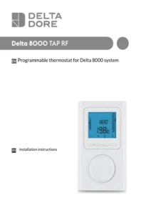
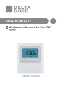
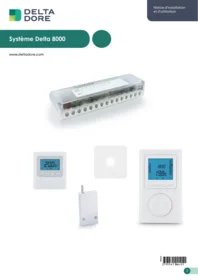
Delta 8000 TAP RF
EN Programmable thermostat for Delta 8000 system

Installation instructions
Contents
1/ Installation....4
2/ Association of the thermostat with the wireless gateway....7
3/ Thermostat configuration....8
4/ Setting the clock 12
5/ Locking down settings 14
6/ Return to initial settings 15
6.1 Initialising the thermostat parameters...... 15
6.2 Deleting the association of the thermostat with the wireless gateway .... 16
7/ Troubleshooting.... 18
8/ Technical characteristics.... 19
EN
1/ Installation
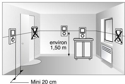
Since the temperature measurement sensor is inside the box, you must install the thermostat:
- wall-mounted or placed on a shelf or a piece of accessible furniture at a height of 1.50 m.
- away from heat sources (fireplaces, sunlight) and draughts (windows, doors)
IMPORTANT: Do not install the thermostat on a wall in contact with the outdoors or with an unheated room (e.g. garage, etc.)
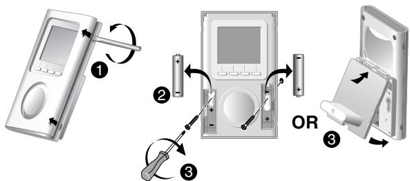
1 Separate the box from its base unit by pushing the pin using a screwdriver.
② Remove the batteries.
3 Attach the box with suitable screws to the mount or mount the thermostat onto its base unit.
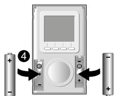
4 When you use the batteries for the first time or replace them, insert them with the right polarity.
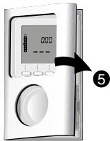
5 Mount the thermostat front panel.
2/ Association of the thermostat with the wireless gateway
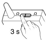
① On the gateway: Press and hold the left hand side button for 3 seconds until LED 1 flashes, then release.
2 On the thermostat: Turn the selector knob to 📄.
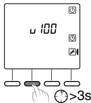
③ Press and hold the second button from the left for 3 seconds, then release.
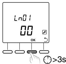
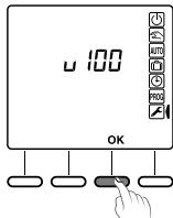
4 The screen displays Ln01. Press OK to display the number of associated products.
5 Press and hold OK for 3 seconds to open the mode for finding products to be associated.
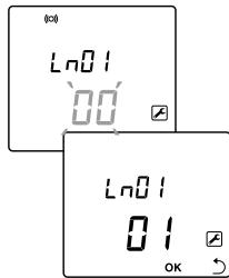
⑥ The display flashes, indicating the number of products found. When the flashing stops, press OK to confirm. LED 1 on the wireless gateway stops flashing.
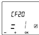
7 The screen displays CF20.
Press OK to open the setting, then press + and - to select the output with which the room thermostat will be associated. Confirm with OK.
⑧ The screen displays CF21.
Press OK to open the setting, then press + and - to select the type of transmitter. Confirm with OK.
9 The screen displays CF22.
Press OK to open the setting, then press + and - to select the limitation value.
Confirm with OK.
9 The screen displays CF22.
Press OK to open the setting, then press + and - to select the limitation value.
Confirm with OK.
Press ← or turn the selector knob to exit the active mode.
| CF20 | Output number | 1 to 16 depending on the system. | |
| CF21 | Transmitter type | 0 | Underfloor heating (by default) |
| 1 | Heater | ||
| CF22 | Heating percentage limitation | From 10 to 100% in increments of 10 (100%= No limitation, by default). | |
3/ Thermostat configuration
① Turn the selector knob to 📄.
② Press OK.
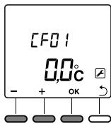
③ The screen displays CF01.
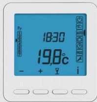
- Press + or - to select the menu.
- Press OK to enter the setting mode, then + and - to perform the setting.
| CFOS | Master thermostat | Zone thermostat |
| Temperature management | Controlled zone | Controlled zone |
| On/Off management | All zones | Controlled zone |
| HEAT/COOL mode management | All zones | - |
| CFO1 | Correction of the measured temperature | +/- 5°C in increments of 0.1°C (0°C by default) | |
| CFO2 | Temperature displayed (after activating the thermostat) | 0 | Setting display (default selection) |
| 1 | Display of the measured temperature. | ||
| CFO3(1) | Ban on the Cool regulation on the Thermostat's thermal zones (if SW2 = ON on the technical unit) | 0 | No ban (default selection) |
| 1 | Ban | ||
| CFO4 | Display the status (ON) of the associated output | 0 | No (default selection) |
| 1 | Yes | ||
| CFO5(2) | Thermostat type | 0 | Zone thermostat (default selection) |
| 1 | Master thermostat | ||
(1) CF03 only appears in Heat/Cool generation mode (SW2=ON, refer to the technical unit manual) and for underfloor heating (CF21=0).
(2) CF05: The Master thermostat enables centralised ON/OFF and HEAT/COOL operations to be performed (according the the technical unit's configuration).
3/ Thermostat configuration
 | Activation of the door/window magnetic contact function (the room thermostat switches to Frost Protection mode if the door/window magnetic contact is activated). | 0 | Not activated |
| 1 | Active (default selection) - Display of the symbol | ||
 | This menu is only available if CF06 = 1. The symbol will flash in the event of detection. | 0 | Not flashing |
| 1 | Flashes in case of detection (default selection) | ||
 | 'Presence detection' function (the thermostat setting is lowered if no presence is detected). | 0 | Not activated |
| 1 | Activated (default selection) | ||
 | Displays the time and date in the 12h/24h format | 0 | 12h (AM/PM) |
| 1 | 24h (default selection) | ||
 | Standby mode | 0 | Display off after a 10-second time-out period |
| 1 | Display illuminated continuously (default selection) | ||
| 2 | Display off (10-second time-out period) from 23.00 to 6.00. Display on from 6.00 to 23.00. | ||
 | Backlighting | 0 | Deactivated |
| 1 | When activated, it goes out after a 5-second time-out period (default) | ||
 | Output number | 1 to 16 depending on the system. '-' is displayed if none are allocated. | |
 | Transmitter type | 0 | Underfloor heating (by default) |
| 1 | Heater | ||
 | Heating percentage limitation | From 10 to 100% in increments of 10 (100%= No limitation, by default). | |
4/ Setting the clock
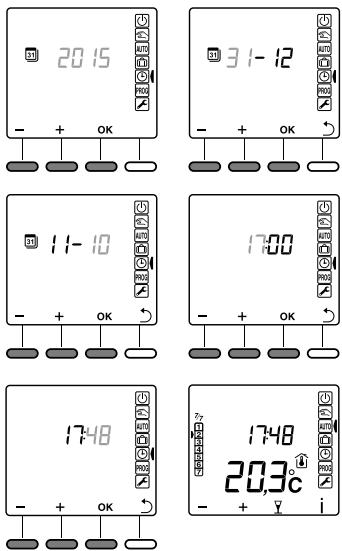
① Turn the selector knob to ⏻.
② Set the year with + and - and confirm with OK.
③ Set the day and month with + and - and confirm with OK.
4 Set the hour value with + and - and confirm with OK.
5 Set the minutes value with + and - and confirm with OK.
6 Back to the AUTO, Manual or Shutdown mode.
Press ↩ to return to the previous setting..
You can decide not to use the calendar function (no automatic changeover between summer and winter).
In this case, when you select the year, select '----' by pressing on -.
5/ Locking down settings
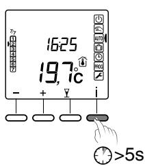
From the AUTO, ⏻, or 📋 modes.
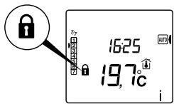
Press and hold the 'i' button for 5 seconds.
The 🔒 symbol appears.
In Lock mode, only the Information button (i) is active.
To unlock, press and hold the i button for 5 seconds.
The 🔒 symbol disappears.
6/ Return to initial settings
6.1 Initialising the thermostat parameters
This menu restores the system to factory settings.
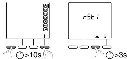
① From the ⏻ (or OFF) mode.
Simultaneously press the 1st and 4th buttons from the left (i) for 10 seconds. Release.
② The screen displays rSt1.
Press and hold OK for 3 seconds until the rSt1 display flashes. Release.
The system automatically returns to STOP mode.
6/ Return to initial settings
6.2 Deleting the association of the thermostat with the wireless gateway
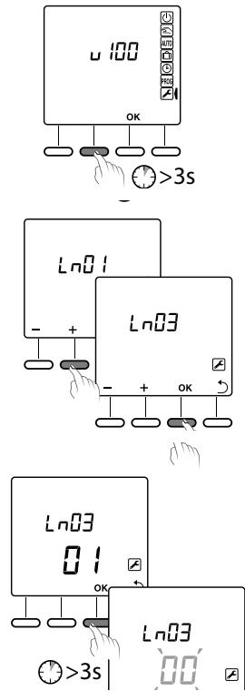
① Turn the selector knob to 📄.
② Press and hold the 2nd button from the left for 3 seconds. Release.
③ The screen displays Ln01. Press + to display Ln03.
4 Press OK. The screen displays the number of products found. Press and hold OK for 3 seconds. The display flashes for 2 seconds and returns to 00. Release.
Press ↩ or turn the selector knob to exit the active mode.
If the display does not return to 00, this means that some products are not responding. To delete them, start again with Ln04 (3).
7/ Troubleshooting
- The screen displays the □ symbol.
The batteries are spent. Replace the batteries
When a defect is detected on the system, the symbol ⚠️ flashes on the thermostat display.
Press 'i' to display the type of defect.
Error messages
| Er-32 | Address error. Several products were assigned to the same output (CF20). |
| Er-33 | Thermostat internal sensor shorted |
| Er-34 | Thermostat internal sensor cut off |
| Er-35 | Error on the outdoor sensor associated with the thermostat channel |
| Er-49 | At least one wireless thermostat (X3D) of the system is no longer detected. |
8/ Technical characteristics
• Power supplied by 2 batteries:
- Alcaline 1.5V, LR03/AAA, battery life 5 years or
- Lithium 1.5 V, LR03/AAA, 1200 mAh, battery life 10 years
- Type 1 automatic action
• Class III insulation
- 868 MHz transmission frequency, class I (standard EN 300 220)
- Wireless remote control
- Wireless range of up to 300 metres outside, varies depending on the associated equipment (the range can vary depending on the installation conditions and the electromagnetic environment).
• Dimensions: 81 x 135 x 22 mm
• Protection rating: IP 30
- Wall mounted or fitted on flush-mounted box
• Storage temperature: -10°C to +70°C
- Operating temperature: 0°C to +40°C
- Rated impulse withstand voltage: 0,33kVac
• Installation in an environment with normal pollution levels

www.deltadore.com
- DELTA 8000 TAP RF
- CONTENTS
- 1/ INSTALLATION
- 2/ ASSOCIATION OF THE THERMOSTAT WITH THE WIRELESS GATEWAY
- 3/ THERMOSTAT CONFIGURATION
- 4/ SETTING THE CLOCK
- 5/ LOCKING DOWN SETTINGS
- 6/ RETURN TO INITIAL SETTINGS
- 6.1 INITIALISING THE THERMOSTAT PARAMETERS
- 6.2 DELETING THE ASSOCIATION OF THE THERMOSTAT WITH THE WIRELESS GATEWAY
- 7/ TROUBLESHOOTING
- 8/ TECHNICAL CHARACTERISTICS
Marque : DELTA DORE
Modèle : Delta 8000 TAP RF
Catégorie : Thermostat