
DGND3300V2 - Routeur ADSL NETGEAR - Notice d'utilisation et mode d'emploi gratuit
Retrouvez gratuitement la notice de l'appareil DGND3300V2 NETGEAR au format PDF.
| Type de produit | Routeur modem ADSL2+ sans fil double bande N300 |
| Dimensions | Environ 223 x 153 x 31 mm (non certifié) |
| Poids | Environ 400 g (non certifié) |
| Alimentation | Adaptateur secteur 12 V / 1,5 A |
| Normes sans fil | 802.11n, 802.11g, 802.11b (2,4 GHz) et 802.11a (5 GHz) |
| Débit sans fil maximal | Jusqu'à 300 Mbps sur 2,4 GHz et 145 Mbps sur 5 GHz |
| Ports | 4 ports LAN Ethernet 10/100/1000, 1 port WAN ADSL2+, 1 port USB 2.0 |
| Sécurité sans fil | WEP, WPA-PSK, WPA2-PSK, WPS (Push 'N' Connect), filtrage MAC |
| Fonctions VPN | Client-to-gateway et gateway-to-gateway, jusqu'à 10 tunnels |
| Stockage USB | Partage de fichiers, serveur multimédia DLNA, accès FTP à distance |
| Pare-feu | NAT, SPI, filtrage de ports, règles de pare-feu personnalisées |
| Contrôle parental | NETGEAR Live Parental Controls (OpenDNS), blocage par mots-clés et planning |
| Gestion à distance | Oui, via l'interface Web |
| Entretien et nettoyage | Débrancher l'alimentation, nettoyer avec un chiffon doux sec. Éviter les liquides. |
| Sécurité | Conforme aux normes FCC et CE. Ne pas utiliser à moins de 20 cm du corps. |
| Pièces détachées et réparabilité | Non spécifié. Contacter le support NETGEAR. |
| Informations générales | Marque : NETGEAR, Modèle : DGND3300v2, Garantie : consulter le fabricant. |
FOIRE AUX QUESTIONS - DGND3300V2 NETGEAR
Questions des utilisateurs sur DGND3300V2 NETGEAR
0 question sur cet appareil. Repondez a celles que vous connaissez ou posez la votre.
Poser une nouvelle question sur cet appareil
Téléchargez la notice de votre Routeur ADSL au format PDF gratuitement ! Retrouvez votre notice DGND3300V2 - NETGEAR et reprennez votre appareil électronique en main. Sur cette page sont publiés tous les documents nécessaires à l'utilisation de votre appareil DGND3300V2 de la marque NETGEAR.
MODE D'EMPLOI DGND3300V2 NETGEAR
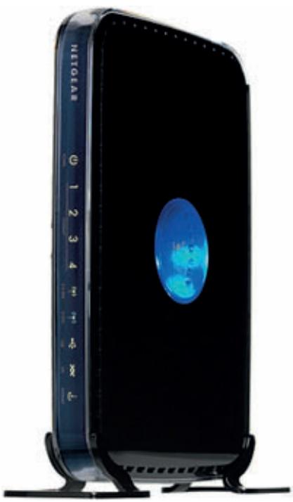
N300 Wireless Dual Band ADSL2+ Modem Router DGND3300v2
User Manual
350 East Plumeria Drive
San Jose, CA 95134
USA
October 2010
202-10463-04
v1.0
©2010 NETGEAR, Inc. All rights reserved.
No part of this publication may be reproduced, transmitted, transcribed, stored in a retrieval system, or translated into any language in any form or by any means without the written permission of NETGEAR, Inc.
Technical Support
Thank you for choosing NETGEAR. To register your product, get the latest product updates, or get support online, visit us at http://support.netgear.com.
Phone (US & Canada only): 1-888-NETGEAR
Phone (Other Countries): See Support information card.
Trademarks
NETGEAR, the NETGEAR logo, ReadyNAS, ProSafe, Smart Wizard, and Auto Uplink are trademarks or registered trademarks of NETGEAR, Inc. Microsoft, Windows, Windows NT, and Vista are registered trademarks of Microsoft Corporation. Other brand and product names are registered trademarks or trademarks of their respective holders.
Statement of Conditions
To improve internal design, operational function, and/or reliability, NETGEAR reserves the right to make changes to the products described in this document without notice. NETGEAR does not assume any liability that may occur due to the use, or application of, the product(s) or circuit layout(s) described herein.
Table of Contents
Chapter 1 Router Internet Setup
Using the Setup Manual. 7
Logging In to Your N300 Wireless Modem Router 8
Using the Setup Wizard 9
Viewing or Manually Configuring Your ISP Settings. 10
Configuring ADSL Settings. 14
Chapter 2 Wireless Settings
Planning Your Wireless Network 15
Wireless Placement and Range Guidelines 16
Wireless Security Options 17
Manually Configuring Your Wireless Settings 18
Configuring WEP Wireless Security 20
Configuring WPA, WPA2, or Mixed WPA2 + WPA Wireless Security . .22
Using Push 'N' Connect (WPS) to Configure Your Wireless Network . . . .24
Using a WPS Button to Add a WPS Client 24
Using PIN Entry to Add a WPS Client 25
Configuring Advanced WPS Settings 27
Connecting Additional Wireless Client Devices after WPS Setup . 27
Adding More WPS Clients 28
Adding Both WPS and Non-WPS Clients 28
Restricting Access to Your N300 Wireless Modem Router 29
Wireless Guest Networks 30
Live Parental Controls 32
Chapter 3 Security Settings
Protecting Access to Your N300 Wireless Modem Router. 34
Changing the Built-In Password 35
Restricting Access by MAC Address 35
Blocking Access to Internet Sites 37
Firewall Rules 38
Port Forwarding 41
Adding a Pre-set Port Forwarding Rule 42
Adding a Custom Port Forwarding Rule 42
Port Triggering 43
Blocking Access to Internet Services 44
Scheduling Blocking 45
Viewing Logs of Web Access or Attempted Web Access. 46
Configuring Email Alert and Web Access Log Notifications 47
Setting the Time 49
Chapter 4 Network Maintenance
Upgrading the Firmware 50
Manually Check for Firmware Upgrades 51
Viewing N300 Wireless Modem Router Status Information 52
Connection Status 55
Statistics 56
Viewing a List of Attached Devices 57
Managing the Configuration File 57
Backing Up and Restoring the Configuration 58
Erasing the Configuration 58
Running Diagnostic Utilities and Rebooting the Router 58
Enabling Remote Management Access 59
Traffic Meter 61
Chapter 5 USB Storage
USB Drive Requirements 65
File Sharing Scenarios 65
Sharing Photos with Friends and Family 66
Storing Files in a Central Location for Printing 66
Sharing Large Files with Colleagues 66
USB Storage Basic Settings. 67
Editing a Network Folder 68
Configuring USB Storage Advanced Settings 69
Creating a Network Folder 71
Media Server Settings 72
Unmounting a USB Drive 72
72
Connecting to the USB Drive from a Remote Computer 73
Locating the Internet Port IP Address. 73
Accessing the Router's USB Drive Remotely Using FTP. 74
Connecting to the USB Drive with Microsoft Network Settings 74
Enabling File and Printer Sharing. 74
Chapter 6 Virtual Private Networking
Overview of VPN Configuration 76
Client-to-Gateway VPN Tunnels. 77
Gateway-to-Gateway VPN Tunnels 77
Planning a VPN 78
VPN Tunnel Configuration 79
Setting Up a Client-to-Gateway VPN Configuration 80
Step 1: Configure the Client-to-Gateway VPN Tunnel .80
Step 2: Configure the NETGEAR ProSafe VPN Client. 83
Setting Up a Gateway-to-Gateway VPN Configuration 90
VPN Tunnel Control 94
Activating a VPN Tunnel. 94
Verifying the Status of a VPN Tunnel 97
Deactivating a VPN Tunnel. 98
Deleting a VPN Tunnel 100
Setting Up VPN Tunnels in Special Circumstances 100
Using Auto Policy to Configure VPN Tunnels. 101
Using Manual Policy to Configure VPN Tunnels 109
Chapter 7 Advanced Settings (Part 1)
Using the LAN Setup Options. 112
Using the N300 Wireless Modem Router as a DHCP Server. 114
Address Reservation 115
Using a Dynamic DNS Service. 116
Configuring the WAN Setup Options 117
Setting Up a Default DMZ Server 119
Setting Up Quality of Service (QoS) 119
Configuring QoS for Internet Access 120
Editing or Deleting an Existing QoS Policy 123
Configuring Static Routes 123
Wireless Repeating (Also Called WDS) 125
Wireless Repeating Function 126
Setting Up the Base Station 127
Setting Up a Repeater Unit. 128
Chapter 8 Advanced Settings (Part 2)
Common Connection Types 130
Assessing Your Speed Requirements 131
Optimizing Your Network Bandwidth 132
Optimizing Wireless Performance 133
Changing the MTU Size 134
Universal Plug and Play 135
Appendix A Troubleshooting
Quick Tips. 137
Troubleshooting with the LEDs. 138
Cannot Access the N300 Wireless Modem Router Menu 140
Cannot Access the Internet 141
Checking the Configuration 141
Checking the WAN IP Address. 141
Troubleshooting a Network Using the Ping Utility 142
Testing the LAN Path to Your Router 143
Testing the Path from Your Computer to a Remote Device 143
Problems with Date and Time 144
Wireless Connectivity 145
Viewing Available Networks 145
Appendix B Default Configuration and Technical Specifications
Restoring the Factory Configuration Settings. 147
Using the Restore Factory Settings Button 147
Technical Specifications. 150
Appendix C NETGEAR VPN Configuration
Configuration Profile. 151
Step-by-Step Configuration 152
N300 Wireless Modem Router with FQDN to Gateway B 153
Configuration Profile. 153
Step-by-Step Configuration 155
Configuration Summary (Telecommuter Example) 157
Setting Up Client-to-Gateway VPN (Telecommuter Example) 158
Step 1: Configure Gateway A (VPN Router at Main Office) .159
Step 2: Configure Gateway B (VPN Router at Regional Office). .160
Monitoring the VPN Tunnel (Telecommuter Example) 166
Viewing the VPN Router'sVPNStatusandLogInformation.167
Appendix D Notification of Compliance
Appendix E Related Documents
Index
Router Internet Setup
Connecting to the network
1
This chapter describes how to configure your N300 Wireless Modem Router Internet connection. When you install your N300 wireless modem router using the Resource CD as described in the N300 Wireless Dual Band ADSL2+ Modem Router Installation Guide, these settings are configured automatically for you. This chapter provides instructions on how to log in to the N300 wireless modem router for further configuration.
Note: NETGEAR recommends that Windows users use the Smart Wizard™ on the Resource CD for initial configuration. Mac and Linux OS users should access the Setup Manual on the Resource CD.
This chapter includes the following sections:
Using the Setup Manual on page 7
- Logging In to Your N300 Wireless Modem Router on page 8
Using the Setup Wizard on page 9
Viewing or Manually Configuring Your ISP Settings on page 10
- Configuring ADSL Settings on page 14
Using the Setup Manual
For first-time installation of your wireless N300 wireless modem router, refer to the Setup Manual. The Setup Manual explains how to launch the NETGEAR Smart Wizard on the Resource CD to step you through the procedure to connect your N300 wireless modem router and computers. The Smart Wizard will assist you in configuring your wireless settings and enabling wireless security for your network. After initial configuration using the Setup Manual, you can use the information in this User Manual to configure additional features of your wireless N300 wireless modem router.
For installation instructions in a language other than English, see the language options on the Resource CD.
Logging In to Your N300 Wireless Modem Router
You can log in to the N300 wireless modem router to view or change its settings. Links to the Knowledge Base and documentation are also available on the N300 wireless modem router main menu.
Note: Your computer must be configured for DHCP. For help with configuring DHCP, see the documentation that came with your computer, or click the link to the online document Preparing Your Network in Appendix E.
When you have logged in, if you do not clickLogout, the N300 wireless modem router waits for 5 minutes after no activity before it automatically logs you out.
To log in to the N300 wireless modem router:
- Type http://www.routerlogin.net, or http://www.routerlogin.com, or the N300 wireless modem router's LAN IP address (the default is 192.168.0.1) in the address field of your browser, and then press Enter. A login window displays:
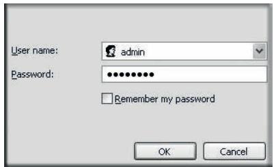
Figure 1.
- Enter admin for the N300 wireless modem router user name and your password (or the default, password). For information about how to change the password, see Changing the Built-In Password on page 35.
Note: The N300 wireless modem router user name and password are not the same as any other user name or password you might use to log in to your Internet connection.
If the N300 wireless modem router has never been configured, the Smart Wizard screen displays. After the N300 wireless modem router has been configured, the Firmware Upgrade assistant will appear. See Using the Setup Wizard on page 9.
- Checking for Firmware Updates screen. After the initial configuration, the Firmware Update screen displays unless you previously cleared the Check for Updated Firmware Upon Log-in check box.
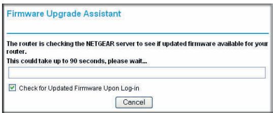
Figure 2.
Note: If the N300 wireless modem router is not configured (is in its factory default state) when you log in, the Setup Wizard displays. See Using the Setup Wizard on page 9.
If the N300 wireless modem router discovers a newer version of the firmware, you are asked if you want to upgrade to the new firmware (see Upgrading the Firmware on page 50 for details). If no new firmware is available, the following message displays.
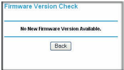
Figure 3.
- Router Status screen. The Router Status screen displays if the N300 wireless modem router has not been configured yet or has been reset to its factory default settings. See Viewing N300 Wireless Modem Router Status Information on page 52.
You can use the Setup Wizard to automatically detect your Internet connection as described in Using the Setup Wizard on page 9, or you can bypass the Setup Wizard and manually configure your Internet connection as described in Viewing or Manually Configuring Your ISP Settings on page 10.
Using the Setup Wizard
You can manually configure your Internet connection using the Basic Settings screen, or you can allow the Setup Wizard to detect your Internet connection. The Setup Wizard searches your Internet connection for servers and protocols to determine your ISP configuration. This feature is not the same as the Smart Wizard on the Resource CD that is used for installation.
To use the Setup Wizard:
- From the top of the main menu, select Setup Wizard.
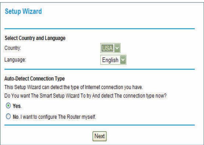
Figure 4.
- Under Auto-Detect Connection Type, select Yes and then click Next to proceed.
- Enter your ISP settings, as needed.
- At the end of the Setup Wizard, click Test to verify your Internet connection. If you have trouble connecting to the Internet, see Troubleshooting in Appendix A."
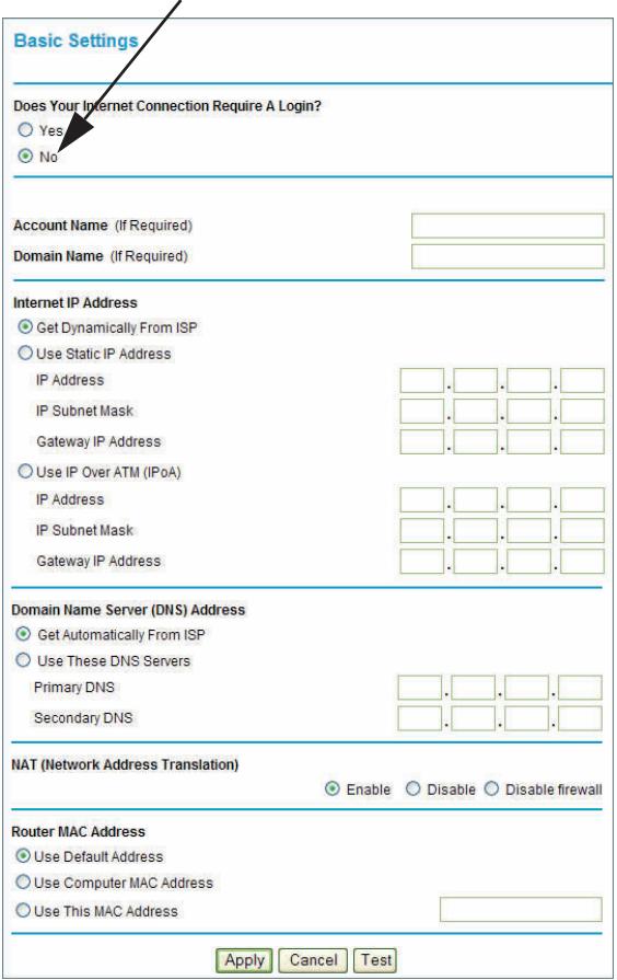
Viewing or Manually Configuring Your ISP Settings
To view or configure the basic settings:
- Log in to the N300 wireless modem router as described in Logging In to Your N300 Wireless Modem Router on page 8.
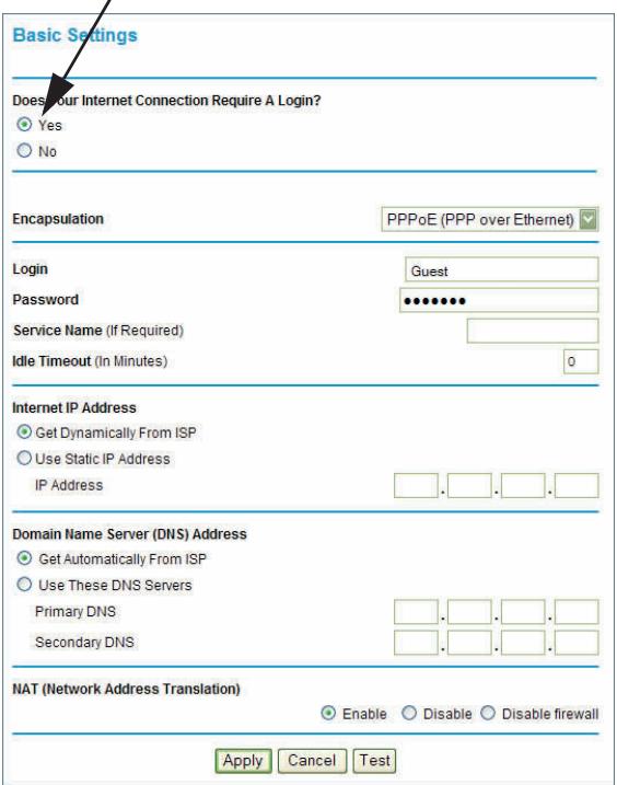
- From the N300 wireless modem router menu, select Basic Settings to display the Basic Settings screen:
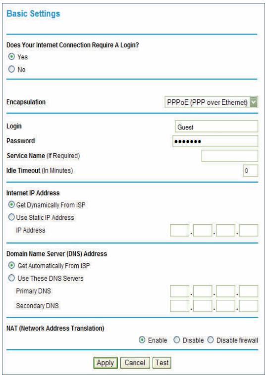
Figure 5.
-
Select Yes or No depending on whether your ISP requires a login. This selection changes the fields available on the Basic Settings screen.
-
Yes. If your ISP requires a login, select the encapsulation method. Enter the login name. If you want to change the login time-out, enter a new value in minutes.
-
No. If your ISP does not require a login, enter the account name, if required, and the domain name, if required.
-
Enter the settings for the IP address and DNS server. If you enter or change a DNS address, restart the computers on your network so that these settings take effect.
- If no login is required, you can specify the MAC Address setting.
- Click Apply to save your settings.
- Click Test to test your Internet connection. If the NETGEAR website does not appear within one minute, see Troubleshooting in Appendix A.
When your Internet connection is working, you do not need to launch the ISP's login program on your computer to access the Internet. When you start an Internet application, your N300 wireless modem router automatically logs you in.
The fields displayed depend on whether or not your Internet connection requires a login.
ISP does not require login
ISP does require login
Figure 6.
| Settings | Description | |
| Does Your ISP Require a Login? | • Yes • No | |
| These fields appear only if no login is required. | Account Name (If required) | Enter the account name provided by your ISP. This might also be called the host name. |
| Domain Name (If required) | Enter the domain name provided by your ISP. | |
| These fields appear only if your ISP requires a login. | Login | The login name provided by your ISP. This is often an e-mail address. |
| Password | The password that you use to log in to your ISP. | |
| Service Name | If your ISP provided a service name, enter it here. | |
| Idle Timeout (In minutes) | If you want to change the Internet login timeout, enter a new value in minutes. This determines how long the N300 wireless modem router keeps the Internet connection active after there is no Internet activity from the LAN. Entering an Idle Timeout value of 0 (zero) means never log out. | |
| Internet IP Address | • Get Dynamically from ISP. Your ISP uses DHCP to assign your IP address. Your ISP automatically assigns these addresses. • Use Static IP Address. Enter the IP address that your ISP assigned. Also enter the IP subnet mask and the gateway IP address. The gateway is the N300 Wireless Dual Band ADSL2+ Modem Router DGND3300v2. • Use IP Over ATM (PoA). This option is only available if your ISP does not require a log in. | |
| Domain Name Server (DNS) Address | The DNS server is used to look up site addresses based on their names. • Get Automatically from ISP. Your ISP uses DHCP to assign your DNS servers. Your ISP automatically assigns this address. • Use These DNS Servers. If you know that your ISP does not automatically transmit DNS addresses to the N300 wireless modem router during login, select this option, and enter the IP address of your ISP's primary DNS server. If a secondary DNS server address is available, enter it also. | |
| NAT (Net Address Translation) | NAT automatically assigns private IP addresses (10.1.1.x) to LAN-connected devices. • Enable. Usually NAT is enabled. • Disable. This disables NAT, but leaves the firewall active. Disable NAT only if you are sure that you do not require it. When NAT is disabled, only standard routing is performed by this router. Classical routing lets you directly manage the IP addresses that the N300 wireless modem router uses. Classical routing should be selected only by experienced usersa. • Disable firewall. This disables the firewall in addition to disabling NAT. With the firewall disabled, the protections usually provided to your network are disabled. | |
| This field appears only if your ISP does not require a login. | Router MAC Address | Your computer's local address is its unique address on your network. This is also referred to as the computer's MAC (Media Access Control) address. • Use Default MAC Address. This is the usual setting. • Use Computer MAC address. If your ISP requires MAC authentication, you can use this setting to disguise the N300 wireless modem router's MAC address with the computer's own MAC address. • Use This MAC Address. If your ISP requires MAC authentication, you can manually type the MAC address for a different computer. The format for the MAC address is XX:XX:XX:XX:XX:XX. |
a. Disabling NAT reboots the N300 wireless modem router and resets its configuration settings to the factory defaults. Disable NAT only if you plan to install the N300 wireless modem router in a setting where you will be manually administering the IP address space on the LAN side of the router.
Configuring ADSL Settings
Note: For information about how to install ADSL filters, see the Setup Manual.
NETGEAR recommends that you use the Setup Wizard to automatically detect and configure your ADSL settings. This usually works fine. However, if you have technical experience and are sure of the multiplexing method and virtual circuit number for the virtual path identifier (VPI) and virtual channel identifier (VCI), you can specify those settings here.
Note: NETGEAR recommends using the Setup Wizard to automatically configure the ADSL settings.
If your ISP provided you with a multiplexing method or VPI/VCI number, then enter the setting:
- From the main menu, select ADSL Settings to display the ADSL Settings screen.
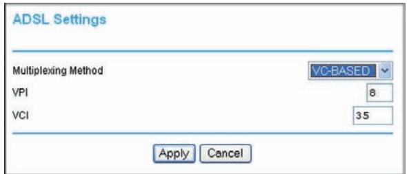
Figure 7.
a. In the Multiplexing Method drop-down list, select LLC-based or VC-based.
b. For the VPI, type a number between 0 and 255. The default is 8.
c. For the VCI, type a number between 32 and 65535. The default is 35.
d. Click Apply.
For a wireless connection, the SSID, also called the wireless network name, and the wireless security setting must be the same for the N300 wireless modem router and wireless computers or wireless adapters. NETGEAR strongly recommends that you use wireless security.

WARNING!
Computers can connect wirelessly at a range of several hundred feet. This can allow others outside of your immediate area to access your network.
This chapter includes the following sections:
- Planning Your Wireless Network on page 15
- Manually Configuring Your Wireless Settings on page 18
- Configuring WEP Wireless Security on page 20
Using Push 'N' Connect (WPS) to Configure Your Wireless Network on page 24 - Connecting Additional Wireless Client Devices after WPS Setup on page 27
Restricting Access to Your N300 Wireless Modem Router on page 29 - Wireless Guest Networks on page 30
Live Parental Controls on page 32
Planning Your Wireless Network
For compliance and compatibility between similar products in your area, the operating channel and region must be set correctly.
To configure the wireless network, you can either specify the wireless settings, or you can use Wi-Fi Protected Setup (WPS) to automatically set the SSID and implement WPA/WPA2 security.
-
To manually configure the wireless settings, you must know the following:
-
SSID. The default 11N SSID for the N300 wireless modem router is NETGEAR-DualBand-N. The default 11G SSID is NETGEAR-2.4-G.
- The wireless mode (802.11g or 802.11b) that each wireless adapter supports.
- Wireless security option. To successfully implement wireless security, check each wireless adapter to determine which wireless security option it supports.
See Manually Configuring Your Wireless Settings on page 18.
- Push 'N' Connect (WPS) automatically implements wireless security on the N300 wireless modem router while, at the same time, allowing you to automatically implement wireless security on any WPS-enabled devices (such as wireless computers and wireless adapter cards). You activate WPS by pressing a WPS button on the N300 wireless modem router, clicking an onscreen WPS button, or entering a PIN number. This generates a new SSID and implements WPA/WPA2 security.
Note: NETGEAR's Push 'N' Connect feature is based on the Wi-Fi Protected Setup (WPS) standard (for more information, see http://www.wi-fi.org). All other Wi-Fi-certified and WPS-capable products should be compatible with NETGEAR products that implement Push 'N' Connect.
To set up your wireless network using the WPS feature:
- Use the N300 wireless modem router dome, which works as a WPS button (there is also an onscreen WPS button), or enter the PIN of the wireless device.
- Make sure that all wireless computers and wireless adapters on the network are Wi-Fi certified and WPA or WPA2 capable, and that they support WPS configuration.
See Using Push 'N' Connect (WPS) to Configure Your Wireless Network on page 24.
Wireless Placement and Range Guidelines
The range of your wireless connection can vary significantly based on the physical placement of the N300 wireless modem router. The latency, data throughput performance, and notebook power consumption of wireless adapters also vary depending on your configuration choices.
For best results, place your N300 wireless modem router according to the following guidelines:
Near the center of the area in which your PCs will operate.
- In an elevated location such as a high shelf where the wirelessly connected PCs have line-of-sight access (even if through walls).
- Away from sources of interference, such as PCs, microwave ovens, and 2.4 GHz cordless phones (see Interference Reduction Table on page 169).
- Away from large metal surfaces.
- Put the antenna in a vertical position to provide the best side-to-side coverage. Put the antenna in a horizontal position to provide the best up-and-down coverage.
- If you are using multiple access points, it is better if adjacent access points use different radio frequency channels to reduce interference. The recommended channel spacing between adjacent access points is 5 channels (for example, use Channels 1 and 6, or 6 and 11).
The time it takes to establish a wireless connection can vary depending on both your security settings and placement. WEP connections can take slightly longer to establish. Also, WEP encryption can consume more battery power on a notebook computer.
Wireless Security Options
Indoors, computers can connect over 802.11g wireless networks at a maximum range of up to 300 feet. Such distances can allow for others outside your immediate area to access your network.
Unlike wired network data, your wireless data transmissions can extend beyond your walls and can be received by anyone with a compatible adapter. For this reason, use the security features of your wireless equipment. The N300 wireless modem router provides highly effective security features, which are covered in detail in this chapter. Deploy the security features appropriate to your needs.
There are several ways you can enhance the security of your wireless network:
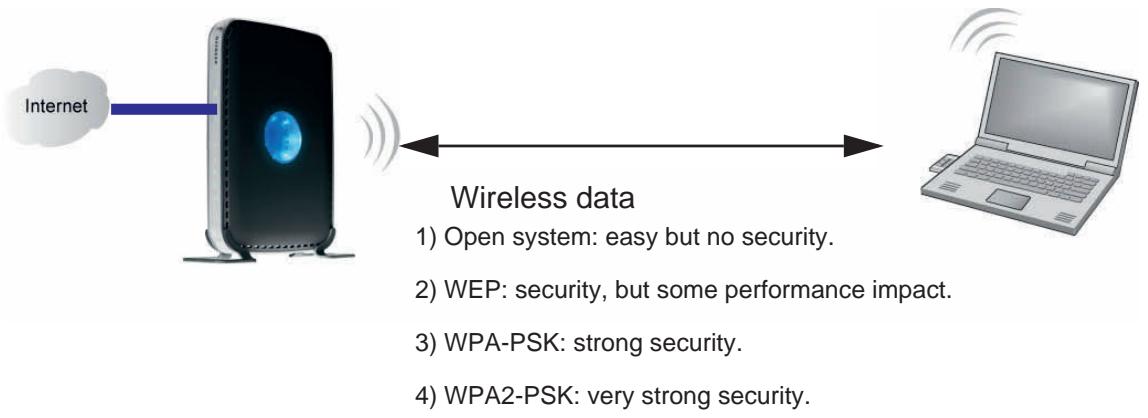
Figure 8.
- WEP. Wired Equivalent Privacy (WEP) data encryption provides data security. WEP Shared Key authentication and WEP data encryption block all but the most determined eavesdropper. This data encryption mode has been superseded by WPA-PSK and WPA2-PSK.
- WPA-PSK (TKIP), WPA2-PSK (AES). Wi-Fi Protected Access (WPA) using a pre-shared key to perform authentication and generate the initial data encryption keys. The very strong authentication along with dynamic per frame rekeying of WPA makes it virtually impossible to compromise.
Note: NETGEAR recommends WPA2 security because it is the strongest, and WPA security as the next strongest. WEP security is the weakest of these alternatives, but you might need to use WEP security to be able to link with your older wireless devices.
For more information about wireless technology, click the link to the online document in Wireless Networking Basics in Appendix E.
Manually Configuring Your Wireless Settings
You can view or manually configure the wireless settings for the N300 wireless modem router in the Wireless Settings screen. If you want to make changes, make sure to note the current settings first.
Note: If you use a wireless computer to change the wireless network name (SSID) or wireless security settings, you will be disconnected when you click Apply. To avoid this, use a computer with a wired connection to access the N300 wireless modem router.
To view or manually configure the wireless settings:
- Log in to the N300 wireless modem router at its default LAN address of http://192.168.0.1 or http://www_ROUTerlogin.net with its default user name of admin, and default password of password, or using whatever user name, password, and LAN address you have chosen for the N300 wireless modem router.
- From the main menu select Wireless Settings to display the Wireless Settings screen:
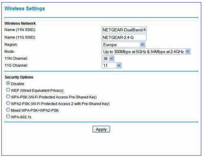
Figure 9.
The settings for this screen are explained in the following table.
| Settings | Description |
| Name (11N SSID) | This is the wireless network name. Enter a 32-character (maximum) name in this field. This field is case-sensitive. |
| Name (11G SSID) | In a setting where there is more than one wireless network, different wireless network names provide a means for separating the traffic. Any device that you want to participate in a wireless network must use the SSID. |
| Region | The location where the N300 Wireless Modem Router is used. |
| Mode | Specify which 802.11 data communications protocol is used. You can select one of the following modes:· Up to 300 Mbps at 2.4 GHz. Performance mode, using channel expansion to achieve the 270 Mbps data rate. The N300 wireless modem router uses the channel you selected as the primary channel and expands to the secondary channel (primary channel +4 or -4) to achieve a 40 MHz frame-by-frame bandwidth. The N300 wireless modem router detects channel usage and disables frame-by-frame expansion if the expansion would result in interference with the data transmission of other access points or clients.· Up to 300 Mbps at 5 GHz and 54 Mbps at 2.4 GHz. This is the default mode, which is recommended.· Up to 145 Mbps at 2.4 GHz. Neighbor friendly mode, for reduced interference with neighboring wireless networks. Provides two transmission streams with different data on the same channel at the same time, but also allows 802.11b and 802.11g wireless devices.· Up to 145 Mbps at 5 GHz and 54 Mbps at 2.4 GHz. Legacy mode, for compatibility with the slower 802.11b and 802.11g wireless devices. |
| 11N Channel | The wireless channel fields determine the operating frequency used for the 11N or 11G wireless networks. Do not change the wireless channel unless you experience interference (shown by lost connections or slow data transfers). If this happens, you might need to experiment with different channels to see which is the best. |
| 11G Channel | |
| Security Options | ·Disable. You can use this setting to establish wireless connectivity before implementing wireless security. NETGEAR strongly recommends that you implement wireless security. ·WEP (Wired Equivalent Privacy). Use encryption keys and data encryption for data security. Select 64-bit or 128-bit encryption. See Configuring WEP Wireless Security on page 20. ·WPA-PSK (Wi-Fi Protected Access Pre-Shared Key). Allow only computers configured with WPA to connect to the N300 wireless modem router. ·WPA2-PSK (Wi-Fi Protected Access with 2 Pre-Shared Keys). Allow only computers configured with WPA2 to connect to the N300 wireless modem router. ·Mixed WPA-PSK + WPA2-PSK. Allow computers configured with either WPA-PSK or WPA2-PSK security to connect to the N300 wireless modem router. ·WPA-802.1x. For information about WPA or WPA2 configuration, see Configuring WPA, WPA2, or Mixed WPA2 + WPA Wireless Security on page 22. |
| WPA2-PSK Security Encryption | Network Key (8–63 characters). |
- Select the region in which the N300 wireless modem router will operate.
- For initial configuration and test, leave the other settings unchanged.
- To save your changes, click Apply.
- Configure and test your computers for wireless connectivity.
Program the wireless adapter of your computers to have the same SSID and wireless security settings as your N300 wireless modem router. Check that they have a wireless link and are able to obtain an IP address by DHCP from the N300 wireless modem router. If there is interference, adjust the channel.
Configuring WEP Wireless Security
Note: If you use a wireless computer to configure wireless secure settings, you will be disconnected when you click Apply.
Reconfigure your wireless computer to match the new settings, or access the N300 wireless modem router from a wired computer to make further changes.
Note: NETGEAR recommends WPA2 security because it is the strongest, and WPA security as the next strongest. WEP security is the weakest of these alternatives, but you might need to use WEP security to be able to link with your older wireless devices.
To configure WEP data encryption:
- Log in to the N300 wireless modem router at its default LAN address of http://192.168.0.1 or http://www_ROUTerlogin.com with its default user name of admin, and default password of password, or using whatever user name, password, and LAN address you have chosen for the N300 wireless modem router.
- From the main menu, select Wireless Settings to display the Wireless Settings screen.
- In the Security Options section, select the WEP radio button:
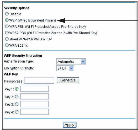
Figure 10.
- In the Authentication Type list, select Automatic, Open System, or Shared Key. The default is Open System.
Note: The authentication scheme is separate from the data encryption. You can select an authentication scheme that requires a shared key but still leaves the data transmissions unencrypted. If you require strong security, use both the Shared Key and WEP encryption settings.
-
Select the Encryption Strength setting:
-
WEP 64 bit. Enter 10 hexadecimal digits (any combination of 0–9, a–f, or A–F).
WEP 128 bit. Enter 26 hexadecimal digits (any combination of 0-9, a-f, or A-F). -
Enter the encryption keys. You can manually or automatically program the four data encryption keys. These values must be identical on all computers and access points in your network:
-
Passphrase. To use a passphrase to generate the keys, enter a passphrase, and click Generate. This automatically creates the keys. Wireless stations must use the passphrase or keys to access the N300 wireless modem router.
Note: Not all wireless adapters support passphrase key generation.
Key 1-Key4. These values are not case-sensitive. You can manually enter the four data encryption keys. These values must be identical on all computers and access points in your network. Enter 10 hexadecimal digits (any combination of 0-9, a-f, or A-F).
- Select which of the four keys will be the default.
Data transmissions are always encrypted using the default key. The other keys can be used only to decrypt received data. The four entries are disabled if WPA-PSK or WPA authentication is selected.
- Click Apply to save your settings.
Configuring WPA, WPA2, or Mixed WPA2 + WPA Wireless Security
To set up wireless security, either you can manually configure it in the Wireless Settings screen, or you can use Wi-Fi Protected Setup (WPS) to automatically set the SSID and implement WPA/WPA2 security (see Using Push 'N' Connect (WPS) to Configure Your Wireless Network on page 24). WPA2 is the strongest security setting and is recommended if the client supports it.
Both WPA and WPA2 provide strong data security. WPA with TKIP is a software implementation that can be used on Windows systems with Service Pack 2 or later; WPA2 with AES is a hardware implementation; see your device documentation before implementing it. Consult the product documentation for your wireless adapter for instructions for configuring WPA settings.
Note: If you use a wireless computer to configure wireless security settings, you will be disconnected when you click Apply. If this happens, reconfigure your wireless computer to match the new settings, or access the N300 wireless modem router from a wired computer to make further changes.
To configure WPA or WPA2 in the N300 wireless modem router:
- Log in to the N300 wireless modem router at its default LAN address of http://192.168.0.1 or http://www_ROUTerlogin.net with its default user name of admin and default password of password, or using whatever user name, password, and LAN address you have chosen for the N300 wireless modem router.
- From the main menu select Wireless Settings.
- On the Wireless Setting screen, select the radio button for the WPA or WPA2 option of your choice.
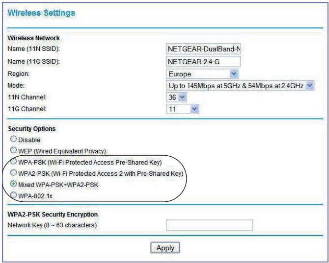
Figure 11.
- The settings displayed on the screen depend on which security option you select.
- For WPA-PSK or WPA2-PSK, enter the passphrase.
- If prompted, enter the settings for the RADIUS server. For WPA-802.1x or WPA2-802.1x, these settings are required for communication with the primary RADIUS server.
Note: RADIUS server applies only to WPA-802.1x, and not to Mixed WPA + WPA2.
- Primary Radius Server IP Address. The IP address of the RADIUS server. The default is 0.0.0.0.
- Radius Port. Port number of the RADIUS server. The default is 1812.
-
Shared Key. This is shared between the wireless access point and the RADIUS server during authentication.
-
To save your settings, click Apply.
Using Push 'N' Connect (WPS) to Configure Your Wireless Network
If your wireless clients support Wi-Fi Protected Setup (WPS), you can use this feature to configure the N300 wireless modem router's SSID and security settings and, at the same time, connect the wireless client securely and easily to the N300 wireless modem router. Look for the symbol on your client device (computers that will connect wirelessly to the N300 wireless modem router are clients). WPS automatically configures the network name (SSID) and wireless security settings for the N300 wireless modem router (if the N300 wireless modem router is in its default state) and broadcasts these settings to the wireless client.
Note: NETGEAR's Push 'N' Connect feature is based on the Wi-Fi Protected Setup (WPS) standard (for more information, see http://www.wi-fi.org). All other Wi-Fi-certified and WPS-capable products should be compatible with NETGEAR products that implement Push 'N' Connect.
Some considerations regarding WPS are:
- WPS supports only WPA-PSK and WPA2-PSK wireless security. WEP security is not supported by WPS.
- If your wireless network will include a combination of WPS-capable devices and non-WPS-capable devices, NETGEAR suggests that you set up your wireless network and security settings manually first, and use WPS only for adding additional WPS-capable devices. See Adding Both WPS and Non-WPS Clients on page 28.
You can add a WPS client using the Push Button method or the PIN method.
- Using the Push Button. This is the preferred method. See the following section, Using a WPS Button to Add a WPS Client.
- Entering a PIN. For information about using the PIN method, see Using PIN Entry to Add a WPS Client on page 25.
Using a WPS Button to Add a WPS Client
Any wireless computer or wireless adapter that will connect to the N300 wireless modem router wirelessly is a client. The client must support a WPS button, and must have a WPS configuration utility, such as the NETGEAR Smart Wizard or Atheros Jumpstart.
To use the N300 wireless modem router WPS button to add a WPS client:
- Log in to the N300 wireless modem router at its default LAN address of http://192.168.0.1 or http://www_ROUTerlogin.net with its default user name of admin
and default password of password, or using whatever LAN address and password you have set up.
- On the N300 wireless modem router main menu, select Add WPS Client, and then click Next. The following screen displays:
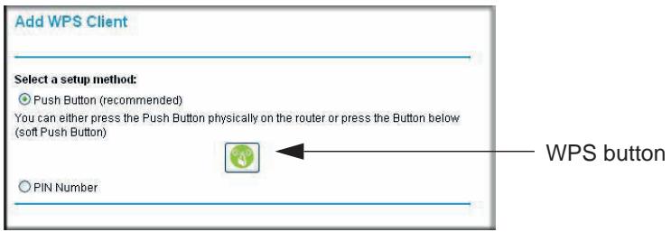
Figure 12.
By default, the Push Button (recommended) radio button is selected.
- Either press the N300 wireless modem router dome for a few seconds, which works as a WPS button, or click the onscreen button.
The N300 wireless modem router tries to communicate with the client for 2 minutes. - Go to the client wireless computer, and run a WPS configuration utility. Follow the utility's instructions to click a WPS button.
- Go back to the N300 wireless modem router screen to check for a message.
The N300 wireless modem router WPS screen displays a message confirming that the client was added to the wireless network. The N300 wireless modem router generates an SSID and implements WPA/WPA2 wireless security. The N300 wireless modem router will keep these wireless settings unless you change them or you clear the Keep Existing Wireless Settings check box in the Advanced Wireless Settings screen. See Restricting Access to Your N300 Wireless Modem Router on page 29.
6. Note the new SSID and WPA/WPA2 password for the wireless network. You can view these settings in the Wireless Settings screen. See Manually Configuring Your Wireless Settings on page 18.
To access the Internet from any computer connected to your N300 wireless modem router, launch a browser such as Microsoft Internet Explorer or Mozilla Firefox. You should see the N300 wireless modem router's Internet LED blink, indicating communication to the ISP.
Note: If no WPS-capable client devices are located during the 2-minute time frame, the SSID will not be changed, and no security will be implemented on the N300 wireless modem router.
Using PIN Entry to Add a WPS Client
Any wireless computer or wireless adapter that will connect to the N300 wireless modem router wirelessly is a client. The client must support a WPS PIN, and must have a WPS configuration utility, such as the NETGEAR Smart Wizard or Atheros Jumpstart.
The first time you add a WPS client, make sure that the Keep Existing Wireless Settings check box on the WPS Settings screen is cleared. This is the default setting for the N300 wireless modem router, and allows it to generate the SSID and WPA/WPA2 security settings when it implements WPS. After WPS is implemented, the N300 wireless modem router automatically selects this check box so that your SSID and wireless security settings remain the same if other WPS-enabled devices are added later.
To use a PIN to add a WPS client:
- Log in to the N300 wireless modem router at its default LAN address of http://192.168.0.1 or http://www.routerlogin.net with its default user name of admin and default password of password, or using whatever LAN address and password you have set up.
- On the N300 wireless modem router main menu, select Add WPS Client (computers that will connect wirelessly to the N300 wireless modem router are clients), and then click Next. The Add WPS Client screen displays:
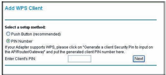
Figure 13.
- Select the PIN Number radio button.
- Go to the client wireless computer. Run a WPS configuration utility. Follow the utility's instructions to generate a PIN. Take note of the client PIN.
- From the N300 wireless modem router Add WPS Client screen, enter the client PIN number, and then click Next.
The N300 wireless modem router tries to communicate with the client for 2 minutes.
- The N300 wireless modem router WPS screen displays a message confirming that the client was added to the wireless network. The N300 wireless modem router generates an SSID, and implements WPA/WPA2 wireless security.
- Note the new SSID and WPA/WPA2 password for the wireless network. You can view these settings in the Wireless Settings screen. See Manually Configuring Your Wireless Settings on page 18.
To access the Internet from any computer connected to your N300 wireless modem router, launch a browser such as Microsoft Internet Explorer or Mozilla Firefox. You should see the N300 wireless modem router's Internet LED blink, indicating communication to the ISP.
Note: If no WPS-capable client devices are located during the 2-minute time frame, the SSID will not be changed and no security will be implemented on the N300 wireless modem router.
Configuring Advanced WPS Settings
From the main menu, select Advanced > Wireless Settings to display the following screen:
Figure 14.
The WPS settings show the N300 wireless modem router PIN and the Disable Router's PIN and Keep Existing Wireless Settings check boxes.
By default, the Keep Existing Wireless Settings check box is cleared. This allows the N300 wireless modem router to automatically generate the SSID and WPA/WPA2 security settings when it implements WPS. After WPS is implemented, the N300 wireless modem router automatically selects this check box so that your SSID and wireless security settings remain the same if you add WPS-enabled devices or if you manually add non-WPS-capable devices later.
Note: If you clear the Keep Existing Wireless Settings check box, all wireless settings and connections will be lost if a WPS client is added.
Connecting Additional Wireless Client Devices after WPS Setup
You can add more WPS clients to your wireless network, or you can add a combination of WPS-enabled clients and clients without WPS.
Adding More WPS Clients
Note: Your wireless settings remain the same when you add another WPS-enabled client, as long as the Keep Existing Wireless Settings check box is selected in the Advanced Wireless Settings screen (select Wireless Settings under Advanced in the N300 wireless modem router main menu). If you clear this check box, when you add the client, a new SSID and passphrase will be generated, and all existing connected wireless clients will be disassociated and disconnected from the N300 wireless modem router.
To add a wireless client device that is WPS enabled:
- Follow the procedures in Using a WPS Button to Add a WPS Client on page 24 or Using PIN Entry to Add a WPS Client on page 25.
- For information about how to view a list of all devices connected to your N300 wireless modem router (including wireless and Ethernet connected), see Viewing a List of Attached Devices on page 57.
Adding Both WPS and Non-WPS Clients
For non-WPS clients, you cannot use the WPS setup procedures to add them to the wireless network. You must record, and then manually enter your security settings (see Manually Configuring Your Wireless Settings on page 18).
To connect a combination of non-WPS-enabled and WPS-enabled clients to the N300 wireless modem router:
- Configure the network names (SSIDs), select the WPA/PSK + WPA2/PSK radio button on the Wireless Settings screen (see Manually Configuring Your Wireless Settings on page 18), and click Apply.
- On the WPA/PSK + WPA2/PSK screen, select a passphrase and click Apply. Record this information to use when you add additional clients.
- For the non-WPS devices that you want to connect, open the networking utility and follow the utility's instructions to enter the SSID, WPA/PSK + WPA2/PSK security method, and passphrase.
- For the WPS devices that you want to connect, follow the procedure in Using a WPS Button to Add a WPS Client on page 24 or Using PIN Entry to Add a WPS Client on page 25.
Note: To make sure that your new wireless settings remain in effect, verify that the Keep Existing Wireless Settings check box is selected in the WPS Settings screen.
- For information about how to view a list of all devices connected to your N300 wireless modem router (including wireless and Ethernet connected), see Viewing a List of Attached Devices on page 57.
Restricting Access to Your N300 Wireless Modem Router
You can use the Advanced Wireless Settings screen to enable or disable the wireless router radio and the SSID broadcast. From the main menu, select Advanced > Wireless Settings to display the following screen:
Figure 15.
- Enable Wireless Access Point. You can completely turn off the wireless portion of the N300 wireless modem router. For example, if you use your notebook computer to wirelessly connect to your N300 wireless modem router, and you take a business trip, you can turn off the wireless portion of the N300 wireless modem router while you are traveling. Other members of your household who use computers connected to the N300 wireless modem router through Ethernet cables can still use the N300 wireless modem router. To do this, clear the Enable Wireless Access Point check box on the Advanced Wireless Settings screen, and then click Apply.
- Allow Broadcast of Name (SSID). Clear this check box to disable broadcast of theSSID, so that only devices that know the correctSSID can connect. DisablingSSID broadcast nullifies the wireless network discovery feature of some products such as Windows XP.
Note: The SSD of any wireless access adapters must match the SSD you configure in the N300 wireless modem router. If they do not match, you will not get a wireless connection to the N300 wireless modem router.
The Fragmentation Threshold, CTS/RTS Threshold, and Preamble Mode options are reserved for wireless testing and advanced configuration only. Do not change these settings.
-
WPS Settings. These are Push 'N' connect settings used by the N300 wireless modem router when WPS clients are added.
-
Router's PIN. The number that the N300 wireless modem router broadcasts when you add a WPS client with the PIN method.
- Disable Router PIN. Selecting this check box disables the N300 wireless modem router's PIN.
- Keep Existing Wireless Settings. This check box is cleared by default so that the N300 wireless modem router network name (SSID) and security can be set automatically if Push 'N' Connect (WPS) is used to set up the network. When the first WPS client is added, this check box is automatically selected so that the SSID and security remain the same when additional clients are added.
For information about adding WPS clients, see Using Push 'N' Connect (WPS) to Configure Your Wireless Network on page 24.
- Restricting access by MAC address. You can use the Wireless Card Access List to restrict access. See Restricting Access by MAC Address on page 35.
Wireless Guest Networks
A wireless guest network allows you to provide guests access to your wireless network without prior authorization of each individual guest. You can configure wireless guest networks and specify the security options for each wireless guest network.
The Guest Network Settings screen that you see depends on the setting in the Wireless Mode field on the Wireless Settings screen and on which selection you make from the main menu. The Guest Network selection is grayed out if it is not available. The following table shows wireless modes, menu selections, and guest networks.
| Mode in Wireless Settings Screen | Menu Selection | Guest Network Default SSID | Wireless Compatibility |
| Up to 300 Mbps at 5 GHz & 54 Mbps at 2.4 GHz (factory default setting) | Guest Network a/n | NETGEAR-5G_a_n_Guest1 | • 5GHz 802.11a • 5GHz 802.11n |
| Guest Network b/g | NETGEAR-2.4G_g_Guest1 | • 2.4GHz 802.11g • 2.4GHz 802.11b | |
| Up to 270 Mpbs | Guest Network b/g/n | NETGEAR-2.4G_n_Guest1 | • 2.4GHz 802.11n • 2.4GHz 802.11g • 2.4GHz 802.11b |
| Up to 145 Mbps at 5 GHz & 54 Mbps at 2.4 GHz | Guest Network a/n | NETGEAR-2.4G_n_Guest1 | • 5GHz 802.11a • 5GHz 802.11n |
| Guest Network b/g | NETGEAR-2.4G_g_Guest1 | • 2.4GHz 802.11g • 2.4GHz 802.11b | |
| Up to 145 Mbps at 2.4 GHz | Guest Network a/n | NETGEAR-2.4G_n_Guest1 | • 2.4GHz 802.11n • 2.4GHz 802.11g • 2.4GHz 802.11b |
To configure a wireless guest network:
- In the main menu, under Setup, select either Wireless Guest Network g/b or Wireless Guest Network a, n. A Wireless Guest Network Settings screen similar to the following figure displays:
Figure 16.
- Make sure that the Enable Guest Network check box is selected.
- You can specify whether the SSID broadcast is enabled, and whether you want to allow guests to access your local network.
- You can also change the guest name in the Guest Wireless Network Name (SSID) field.
Note: NETGEAR strongly recommends that you change the default guest network name (SSID) from the default name to a different name. Note that the name is case-sensitive. For example, GuestNetwork is not the same as Guestnetwork.
Enter a value of up to 32 alphanumeric characters. For the selected guest network, the same name must be assigned to all wireless devices in your network.
Note: Wireless security is disabled by default. NETGEAR strongly recommends that you implement wireless security for the guest network.
- To configure wireless security for the guest network, enter the security options. This process is very similar to configuring wireless security for the N300 wireless modem router. For more information, see Configuring WEP Wireless Security on page 20 and Using Push 'N' Connect (WPS) to Configure Your Wireless Network on page 24.
- When you have finished making changes, click Apply.
Live Parental Controls
NETGEAR Live Parental Controls, powered by OpenDNS, is a router-based Web filtering solution available on NETGEAR Wireless-N router and gateway products. Designed to protect you from identity theft and scams, Live Parental Control blocks up to 50 categories of Internet content.
Live Parental Controls is an excellent solution for keeping your family safe online, but like all Web filtering tools, it is not perfect. NETGEAR reminds you there is no substitute for keeping the family computer in a common area and in plain sight where you can monitor the websites your kids are visiting, and taking caution when visiting websites requesting personal or financial information.
Download Live Parental Controls from this website: http://www.netgear.com/lpc.
Web-Based Interface
Live Parental Controls is the first to allow parents or network administrators to manage settings while away from home or office. This is particularly convenient when access exceptions need to be made. And since settings are stored on the Web, using a browser interface to manage them is not difficult.
Total Home Protection
Live Parental Controls protects all Internet-connected devices through the router. It protects not only computers, but also set-top boxes, iPhones, iPods, and gaming consoles that are attached to your network. You no longer need to worry about phones and gaming consoles not being protected when kids use them in their own rooms. Even guest computers accessing the Internet through your network are protected.
Flexible Settings
You might have your own computer or you might be sharing a computer with other members in the family. Default and per-user settings allow you to customize configurations for different computing arrangements and personalize the settings for each person. Per-time setting allows Internet access during scheduled time slots to help manage the balance between work and play.
Minimal Software Installation
This capability requires a one-time installation of the management utility. Once Live Parental Controls is set up, the software runs in the background and does not interfere with normal Internet usage.
Security Settings
Keeping unwanted content out of your network
3
This chapter describes how to use the content filtering and reporting features of the N300 wireless modem router to protect your network.
This chapter includes the following sections:
Restricting Access by MAC Address on page 35
- Blocking Access to Internet Sites on page 37
- Firewall Rules on page 38
- Port Forwarding on page 41
- Port Triggering on page 43
- Blocking Access to Internet Services on page 44
- Scheduling Blocking on page 45
Viewing Logs of Web Access or Attempted Web Access on page 46
- Configuring Email Alert and Web Access Log Notifications on page 47
Setting the Time on page 49
Note: For information about restricting access to USB storage devices, see Configuring USB Storage Advanced Settings on page 69.
Protecting Access to Your N300 Wireless Modem Router
For security reasons, the N300 wireless modem router has its own user name and password. Also, after a period of inactivity for a set length of time, the administrator login automatically disconnects. When prompted, enter admin for the user name and password for the password. You can use procedures in the following sections to change the password and the amount of time for the administrator's login time-out.
Note: The user name and password are not the same as a user name or password you might use to log in to your Internet connection.
NETGEAR recommends that you change this password to a more secure password. The ideal password should contain no dictionary words from any language, and should be a mixture of both uppercase and lowercase letters, numbers, and symbols. Your password can be up to 30 characters.
Changing the Built-In Password
- Log in to the N300 wireless modem router at its default LAN address of http://192.168.0.1 or http://www+ruterlogin.net with its default user name of admin, default password of password, or using whatever password and LAN address you have chosen for the N300 wireless modem router.
- From the main menu, select Maintenance > Set Password to display the Set Password screen.
- To change the password, first enter the old password, and then enter the new password twice.
- Click Apply to save your changes.
Note: After changing the password, you must log in again to continue the configuration. If you have backed up the N300 wireless modem router settings previously, you should do a new backup so that the saved settings file includes the new password.
Restricting Access by MAC Address
By default, any wireless PC that is configured with the correct SSID will be allowed access to your wireless network. For increased security, you can restrict access to the wireless network to allow only specific PCs based on their MAC addresses.
To restrict access based on MAC addresses:
- Log in to the N300 wireless modem router at its default LAN address of http://192.168.0.1 or http://www_ROUTerlogin.net with its default user name of admin, and default password of password, or using whatever user name, password, and LAN address you have chosen for the N300 wireless modem router.
Note: If you configure the N300 wireless modem router from a wireless computer, add your computer's MAC address to the access list. Otherwise you will lose your wireless connection when you click Apply. You must then access the N300 wireless modem router from a wired computer, or from a wireless computer that is on the access control list, to make any further changes.
- From the main menu, under Advanced > Wireless Settings, and then click Setup Access List to display the Wireless Card Access List screen.
Figure 17.
The Wireless Station Access List screen displays a list of wireless PCs that are allowed to connect to the N300 wireless modem router based on their MAC addresses. These wireless PCs must also have the correct SSID and wireless security settings to access the wireless network.
- Select the Turn Access Control On check box.
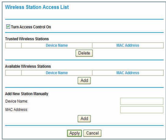
Figure 18.
Note: If the Turn Access Control On check box is selected and the Trusted Wireless Stations list is blank, then no wireless PCs will be able to connect to your wireless network.
-
You can select a wireless station from the Available Wireless Stations list, or you can enter its MAC address manually:
-
If the wireless station is shown in the Available Wireless Stations list, click its radio button to select it, and then click Add.
- To manually specify the wireless station, in the Add New Station Manually section, enter the name of the wireless station and its MAC address. The MAC address is 12 hexadecimal digits and can usually be found on the bottom of the wireless device. Click Add.
The wireless station appears in the Trusted Wireless Stations list.
Note: You can use the Delete button to remove access by a wireless station.
- When you are finished, click Apply to save your changes. Now, only devices on the Trusted Devices list will be allowed to wirelessly connect to the N300 wireless modem router.
Blocking Access to Internet Sites
The N300 wireless modem router allows you to restrict access based on Web addresses and Web address keywords. Up to 255 entries are supported in the Keyword list.
Keyword application examples:
If the keyword XXX is specified, the URL www.zzzyyqq.com/xxx.html is blocked.
- If the keyword .com is specified, only websites with other domain suffixes (such as .edu, .org, or .gov) can be viewed.
To block access to Internet sites:
- Select Security > Block Sites in the main menu. The Block Sites screen displays.
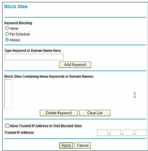
Figure 19.
- Enable keyword blocking by selecting either Per Schedule or Always.
To block by schedule, be sure to specify a time period in the Schedule screen. For information about scheduling, see Scheduling Blocking on page 45.
Block all access to Internet browsing during a scheduled period by entering a dot (.) as the keyword, and then set a schedule in the Schedule screen.
- Add a keyword or domain by entering it in the keyword field and clicking Add Keyword. The keyword or domain name then appears in the Block sites containing these keywords or domain names list.
Delete a keyword or domain name by selecting it from the list and clicking Delete Keyword. - You can specify one trusted user, which is a computer that is exempt from blocking and logging. Specify a trusted user by entering that computer's IP address in the Trusted IP Address fields.
Since the trusted user is identified by IP address, you should configure that computer with a fixed IP address. - Click Apply to save all your settings in the Block Sites screen.
Firewall Rules
You can use this screen to create firewall rules to block or allow specific traffic.
Note: The firewall rules feature is for advanced administrators only! Incorrect configuration will cause serious problems.
The Firewall Rules screen lists all existing rules for outbound traffic and inbound traffic. If you have not defined any rules, only the default rules are listed. You can add or edit rules. You can also use the Move and Delete buttons to move the selected rule to a new position in the table, or to delete the selected rule.
From the main menu, select Security > Firewall Rules to display the following screen:
Figure 20.
- Outbound Services. This lists all existing rules for outbound traffic. If you have not defined any rules, only the default rule is listed. The default rule allows all outgoing traffic.
- Inbound Services. This lists all existing rules for inbound traffic. If you have not defined any rules, only the default rule is listed. The default rule blocks all inbound traffic.
- Ports to enable MSN and AOL Instant Messaging are open by default. To close these ports, select the Close IM Ports radio button, and then click Apply so that your changes take effect. When these ports are closed, Instant Messaging does not function.
To add or edit a rule from the Firewall Rules screen:
- To edit a rule, select its radio button. To add a rule, click Add (it does not matter which radio button is selected).
Depending on your selection, either the Outbound Services screen or Inbound Services screen is displayed.
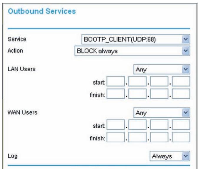
Figure 21.
- From the Service list, select the service that you want to add or edit.
- Enter the settings to specify the service as explained in the following table.
| Field | Outbound Rules | Inbound Rules |
| Action | ·For outbound rules, ALLOW rules are useful only if the traffic is already covered by a BLOCK rule (that is, you want to allow a subset of traffic that is currently blocked by another rule). ·To define the schedule used in these selections, use the Schedule screen (see Scheduling Blocking on page 45). | ·For inbound rules, BLOCK rules are useful only if the traffic is already covered by an ALLOW rule (that is, you want to block a subset of traffic that is currently allowed by another rule). ·To define the schedule used in these selections, use the Schedule screen (see Scheduling Blocking on page 45). |
| LAN users (outbound services only) | These settings determine which computers on your network are affected by this rule, based on their source (LAN) IP address. Select the option you want: ·Any. All local IP addresses are covered by this rule. ·Address range. If this option is selected, you must fill in the Start and Finish fields. ·Single address. Enter the required address in the Start fields. | — |
| Send to LAN Server (inbound services only) | — | Enter the IP address of the PC or server on your LAN that will receive the inbound traffic covered by this rule. |
| WAN Servers | These settings determine which Internet locations are covered by the rule, based on their destination (WAN) IP address. Select the option you want: • Any. All local IP addresses are covered by this rule. • Address range. If this option is selected, you must fill in the Start and Finish fields. • Single address. Enter the required address in the Start fields. | |
| Log | This determines whether packets covered by this rule are logged. Select the action you want: • Always. Always log traffic considered by this rule, whether it matches or not. This is useful when debugging your rules. • Never. Never log traffic considered by this rule, whether it matches or not. • Match. Log traffic only if matches this rule. (The action is determined by this rule.) • Not Match. Log traffic that is considered by this rule, but does not match. (The action is not determined by this rule.) | |
- Click Apply to have your changes take effect.
The new rule will be listed in the table when you return to the Firewall Rules screen.
Port Forwarding
Using the port forwarding feature, you can allow certain types of incoming traffic to reach servers on your local network. For example, you might make a local Web server, FTP server, or game server visible and available to the Internet.
Use the Port Forwarding screen to configure the N300 wireless modem router to forward specific incoming protocols to computers on your local network. In addition to servers for specific applications, you can also specify a default DMZ server to which all other incoming protocols are forwarded. The DMZ server is configured in the WAN Setup screen, as discussed in Configuring the WAN Setup Options on page 117."
Before starting, you need to determine which type of service, application, or game you will provide, and the local IP address of the computer that will provide the service. Be sure the computer's IP address never changes.
Select Security > Port Forwarding in the main menu. The Port Forwarding screen displays:
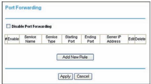
Figure 22.
You can add a pre-set port forwarding rule or a custom rule.
Adding a Pre-set Port Forwarding Rule
- From the Port Forwarding screen, click Add to display the following screen:
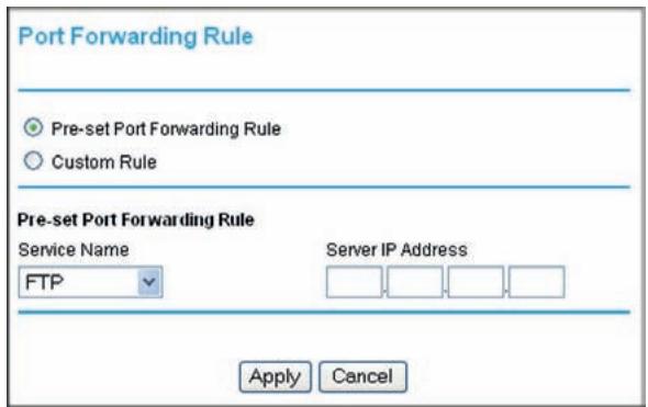
Figure 23.
- In the Service Name list, select the rule.
- Fill in the Server IP Address field, and then click Apply.
Adding a Custom Port Forwarding Rule
- From the Port Forwarding screen, click Add.
- Select the Custom Rule radio button, and the screen changes:
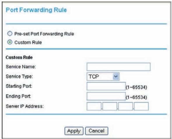
Figure 24.
- In the Service Name field, enter a name.
- In the Service Type list, select the protocol. If you are unsure, select TCP/UDP.
- Fill in the Starting Port and Ending Port fields.
-
In the Server IP Address field, enter the IP address of your local computer that will provide this service.
-
Click Apply. The service appears in the list.
Port Triggering
Port triggering is an advanced feature that can be used to easily enable gaming and other Internet applications that would otherwise be blocked by the firewall. Using this feature requires that you know the port numbers that are used by the application.
Note: For information about port forwarding and port blocking, see Firewall Rules on page 38.
Once configured, port triggering operates as follows:
- A PC makes an outgoing connection using a port number defined in the Port Triggering table.
- The N300 wireless modem router records this connection, opens the incoming port or ports associated with this entry in the Port Triggering List, and associates them with the PC.
- The remote system receives the PC's request, and responds using a different port number.
- The N300 wireless modem router matches the response to the previous request, and forwards the response to the PC. (Without port triggering, this response would be treated as a new connection request rather than a response. As such, it would be handled in accordance with the port forwarding rules.)
Note: Only one PC can use a port triggering application at any time. After a PC has finished using a port triggering application, there is a short time-out period before the application can be used by another PC.
To configure port triggering:
- In the main menu, select Security > Port Triggering. The Port Triggering screen displays.
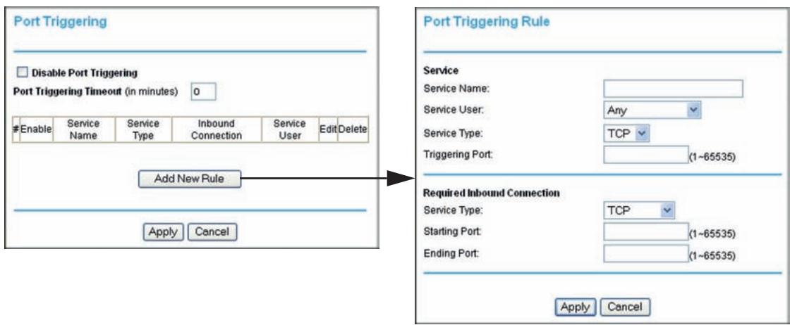
Figure 25.
- Specify the information for port triggering:
Service Name. Enter a name for the rule, up to 30 characters.
- Service User. The PC on the LAN that can use the port triggering rule to create a dynamic inbound mapping to it. There are 2 options:
- The port triggering rule is applied to all PCs on the LAN. That is, any PC on the LAN can use the rule and make the router to open a dynamic mapping to it.
- The port triggering rule is applied only to the user-specified PC on the LAN.
Service Type. Defines whether the traffic is TCP or UDP.
- Triggering Port. The destination port number of the traffic. That is, when there is a packet from a LAN PC that the rule is applied to, with the specified service type and destined to the specified triggering port, the router creates a rule for dynamic mapping to the LAN PC.
- Required Inbound Connection. This defines what the dynamic mapping is. The connection type defines whether the dynamic mapping is for TCP traffic, UDP traffic, or TCP and UDP traffic. The open port range is specified by the starting port and the ending port, and this defines the port that the dynamic mapping is applied to.
- Click Apply to save your settings and activate the port triggers that you have enabled.
Blocking Access to Internet Services
The N300 wireless modem router allows you to block the use of certain Internet services by computers on your network. This is called service blocking or port filtering. Services are functions performed by server computers at the request of client computers. For example, Web servers serve Web pages, time servers serve time and date information, and game hosts serve data about other players' moves. When a computer on your network sends a request for service to a server computer on the Internet, the requested service is identified by a service or port number. This number appears as the destination port number in the transmitted IP packets. For example, a packet that is sent with destination port number 80 is an HTTP (Web server) request.
To block access to Internet services:
- From the main menu, select Security > Services. The Services screen displays.
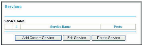
Figure 26.
- To add a service, click Add Custom Service. The following screen displays.
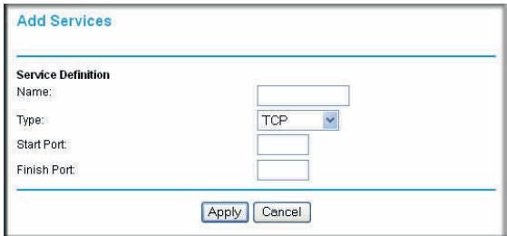
Figure 27.
- Enter a name for the service.
- From the Service Type drop-down list, select the application or service to be allowed or blocked. If you know that the application uses either TCP or UDP, select the appropriate protocol. If you are not sure, select Both.
- You can block the specified service for a single computer, a range of computers with consecutive IP addresses, or all computers on your network. Enter the starting port and ending port numbers. If the application uses a single port number, enter that number in both fields.
You must determine which port number or range of numbers is used by the application. The service port numbers for many common protocols are defined by the Internet Engineering Task Force (IETF) and published in RFC1700, "Assigned Numbers." Service numbers for other applications are typically chosen from the range 1024 to 65535 by the authors of the application. You can often determine port number information by contacting the publisher of the application, by asking user groups or newsgroups, or by searching.
- Click Apply so that your changes take effect.
Scheduling Blocking
To schedule blocking:
- From the main menu, select Security > Schedule. The Schedule screen displays.
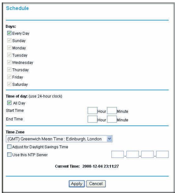
Figure 28.
- Configure the schedule for blocking keywords and services.
a. Days. Select days on which you want to apply blocking by selecting the appropriate check boxes. Select Every Day to select the check boxes for all days. Click Apply.
b. Time of Day. Select a start and end time in 24-hour format. Select All Day for 24-hour blocking. Click Apply.
Be sure to select your time zone in the E-mail screen as described in Setting the Time on page 49.
- Click Apply to save your settings.
Note: For information about setting the time, see Setting the Time on page 49.
Viewing Logs of Web Access or Attempted Web Access
The log is a detailed record of the websites you have accessed or attempted to access. Up to 128 entries are stored in the log. Log entries appear only when keyword blocking is enabled and no log entries are made for the trusted user.
From the main menu, select Security > Logs. The Logs screen displays.
To refresh the log screen, click the Refresh button.
- To clear the log entries, click the Clear Log button.
To e-mail the log immediately, click the Send Log button.
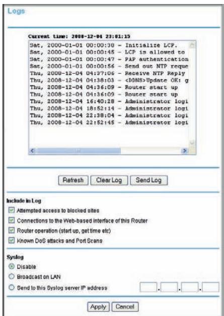
Figure 29.
The following information is provided in the logs:
| Field | Description |
| Date and time | The date and time the log entry was recorded. |
| Source IP | The IP address of the initiating device for this log entry. |
| Target address | The name or IP address of the website or newsgroup visited, or to which access was attempted. |
| Action | Whether the access was blocked or allowed. |
Configuring Email Alert and Web Access Log Notifications
To receive logs and alerts by e-mail, you must provide your e-mail account information.
- From the main menu, select Security > E-mail. The E-mail screen displays.
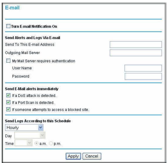
Figure 30.
- To receive email logs and alerts from the N300 wireless modem router, select the Turn E-mail Notification On check box.
a. In the Your Outgoing Mail Server field, enter the name of your ISP's outgoing (SMTP) mail server (such as mail.myISP.com). You might be able to find this information in the configuration screen of your e-mail program. If you leave this field blank, log and alert messages will not be sent by e-mail.
b. In the Send To This E-mail Address field, enter the email address to which logs and alerts are sent. This email address will also be used as the From address. If you leave this field blank, log and alert messages will not be sent by email.
- If your outgoing e-mail server requires authentication, select the My Mail Server requires authentication check box.
a. In the User Name field, enter your user name for the outgoing email server.
b. In the Password field, enter your password for the outgoing email server.
-
You can specify that logs are automatically sent by email with these options:
-
Send alert immediately. Select this check box for immediate notification of attempted access to a blocked site or service.
-
Send Logs According to this Schedule. Specifies how often to send the logs: Hourly, Daily, Weekly, or When Full.
-
Day. Specifies which day of the week to send the log. Relevant when the log is sent weekly or daily.
- Time. Specifies the time of day to send the log. Relevant when the log is sent daily or weekly.
If you select the Weekly, Daily, or Hourly option and the log fills up before the specified period, the log is automatically emailed to the specified email address. After the log is sent, the log is cleared from the N300 wireless modem router's memory. If the N300 wireless modem router cannot e-mail the log file, the log buffer might fill up. In this case, the N300 wireless modem router overwrites the log and discards its contents.
5. Click Apply to save your settings.
So that the log entries are correctly time-stamped and sent at the correct time, be sure to set the time as described in the next section.
Setting the Time
The N300 wireless modem router uses the Network Time Protocol (NTP) to obtain the current time and date from one of several network time servers on the Internet. To localize the time for your log entries, you must specify your time zone:
- Time Zone. Select your local time zone. This setting is used for the blocking schedule and for time-stamping log entries.
- Adjust for Daylight Savings Time. Select this check box when daylight savings time is in effect to adjust the time for your N300 wireless modem router.
This chapter describes features to help you manage your N300 wireless modem router. This chapter includes the following sections:
Upgrading the Firmware on page 50
Viewing N300 Wireless Modem Router Status Information on page 52
Viewing a List of Attached Devices on page 57
- Managing the Configuration File on page 57
- Running Diagnostic Utilities and Rebooting the Router on page 58
Enabling Remote Management Access on page 59
Traffic Meter on page 61
Upgrading the Firmware
The N300 wireless modem router's firmware (routing software) is stored in flash memory. By default, when you log in to your N300 wireless modem router, it automatically checks the NETGEAR website for new firmware and alerts you if there is a newer version.
Checking for Firmware Updates
The router is checking the NETGEAR server to see if upda available for your router.
This could take up to 90 seconds, please wait...
Check for Updated Firmware Upon Log-in
Cancel
Figure 31.
Note: To turn off the automatic firmware check at login, clear the Check for Updated Firmware Upon Log-in check box on the Router Upgrade screen.
If the N300 wireless modem router discovers a newer version of firmware, the message on the left displays. If no new firmware is available, the message on the right displays.
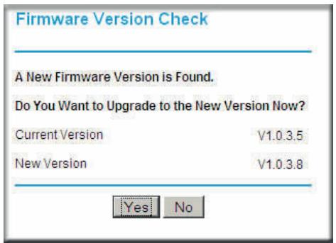
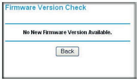
Figure 32.
To upgrade, click Yes to allow the N300 wireless modem router to download and install the new firmware.

WARNING!
When uploading firmware to the N300 wireless modem router, do not interrupt the Web browser by closing the window, clicking a link, or loading a new page. If the browser is interrupted, it could corrupt the firmware.
When the upload is complete, your N300 wireless modem router automatically restarts. The upgrade process could take a few minutes. Read the new firmware release notes to determine whether you must reconfigure the N300 wireless modem router after upgrading.
Manually Check for Firmware Upgrades
You can use the Router Upgrade screen to manually check the NETGEAR website for newer versions of firmware for your product.
To manually check for new firmware and install it on your N300 wireless modem router:
- From the main menu, select Maintenance > Router Status. Note the version number of your N300 wireless modem router firmware.
-
Go to the DGND3300v2 support page on the NETGEAR website at http://www.netgear.com/support.
-
If the firmware version on the NETGEAR website is newer than the firmware on your N300 wireless modem router, download the file to your computer.
- From the main menu, select Maintenance > Router Upgrade to display the following screen:
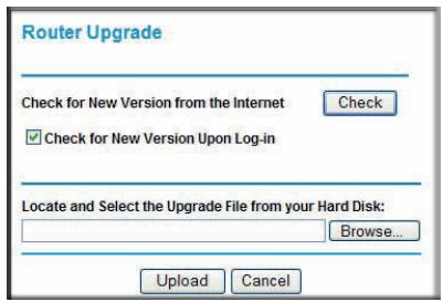
Figure 33.
- Click Browse, and locate the firmware you downloaded (the file ends in .img or .chk).
- Click Upload to send the firmware to the N300 wireless modem router.

WARNING!
When uploading firmware to the N300 wireless modem router, do not interrupt the Web browser by closing the window, clicking a link, or loading a new page. If the browser is interrupted, it could corrupt the firmware.
When the upload is complete, your N300 wireless modem router automatically restarts. The upgrade process typically takes about one minute. Read the new firmware release notes to determine whether you must reconfigure the N300 wireless modem router after upgrading.
Viewing N300 Wireless Modem Router Status Information
To view N300 wireless modem router status and usage information, from the main menu, select Maintenance > Router Status. The Router Status screen displays.
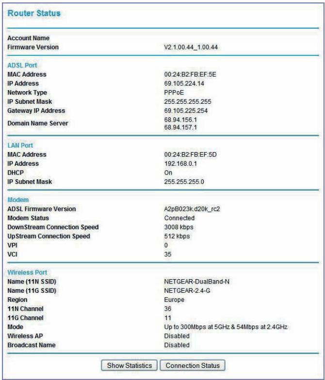
Figure 34.
You can use the Show Statics and Connection Status buttons to view additional status information, as described in Connection Status on page 55 and Statistics on page 56. The following table explains Router Status screen fields.
| Field | Description | |
| Account Name | The host name assigned to the N300 wireless modem router. | |
| Firmware Version | The version of the N300 wireless modem router firmware. It changes if you upgrade the N300 wireless modem router. | |
| Field | Description | |
| Internet Port | MAC Address | The Media Access Control address. This is the unique physical address being used by the Internet (WAN) port of the N300 wireless modem router. |
| IP Address | The IP address being used by the Internet (WAN) port of the N300 wireless modem router. If no address is shown, or is 0.0.0.0, the N300 wireless modem router cannot connect to the Internet. | |
| DHCP | • None. The N300 wireless modem router uses a fixed IP address on the WAN. • DHCP Client. The N300 wireless modem router obtains an IP address dynamically from the ISP. | |
| IP Subnet Mask | The IP subnet mask being used by the Internet (WAN) port of the N300 wireless modem router. For an explanation of subnet masks and subnet addressing, click the link to the online document TCP/IP Networking Basics in Appendix E. | |
| Domain Name Server | The Domain Name Server addresses being used by the N300 wireless modem router. A Domain Name Server translates human-language URLs such as www.netgear.com into IP addresses. | |
| LAN Port | MAC Address | The Media Access Control address. This is the unique physical address being used by the Ethernet (LAN) port of the N300 wireless modem router. |
| IP Address | The IP address being used by the Ethernet (LAN) port of the N300 wireless modem router. The default is 192.168.0.1 (http://www.ruterlogin.net). | |
| DHCP | Identifies whether the firmware's built-in DHCP server is active for the LAN-attached devices. | |
| IP Subnet Mask | The IP subnet mask being used by the Ethernet (LAN) port of the N300 wireless modem router. The default is 255.255.255.0. | |
| Wireless Port | Name (11NSSID) | The 11N wireless network name (SSID) being used by the wireless port of the N300 wireless modem router. The default is NETGEAR-DualBand-N. |
| Name (11GSSID) | The 11G wireless network name (SSID) being used by the wireless port of the N300 wireless modem router. The default is NETGEAR-2.4-G. | |
| Region | The geographic region where the N300 wireless modem router is being used. It might be illegal to use the wireless features of the N300 wireless modem router in some parts of the world. | |
| 11N Channel | Identifies the 11N channel of the wireless port being used. Click the link to the online document Wireless Networking Basics in Appendix E for the frequencies used on each channel. In Up to 300 Mbps at 5 GHz and 54 Mbps at 2.4 GHz mode, there are two channels: a primary channel (P) and a secondary channel (S). | |
| Wireless Port (continued) | 11G Channel | Identifies the 11G channel of the wireless port being used. Click the link to the online document Wireless Networking Basics in Appendix E for the frequencies used on each channel. In Up to 300 Mbps at 2.4 GHz mode and Up to 145 Mbps at 2.4 GHz mode, the 11G channel is not active. |
| Mode | Indicates the wireless communication mode: • Up to 300 Mbps at 2.4 GHz • Up to 300 Mbps at 5 GHz and 54 Mbps at 2.4 GHz (default) • Up to 145 Mbps at 2.4 GHz • Up to 145 Mbps at 5 GHz and 54 Mbps at 2.4 GHz | |
| Wireless AP | Indicates whether the radio feature of the N300 wireless modem router is enabled. If this feature is not enabled, the Wireless light on the front panel is off. | |
| Broadcast Name | Indicates whether the N300 wireless modem router is broadcasting its SSID. | |
Connection Status
To view the connection status, on the Router Status screen, click Connection Status.
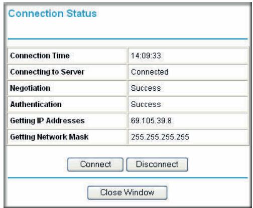
Figure 35.
- Click the Connect button, and the N300 wireless modem router attempts to connect to the Internet.
- Click the Disconnect button to disconnect the N300 wireless modem router Internet connection.
- Click the Close Window button to close the Connection Status screen.
The following table describes the connection status settings.
| Item | Description |
| Connection Time | The time elapsed since the last connection to the Internet through the ADSL port. |
| Connecting to sender | The connection status. |
| Negotiation | Success or Failed. |
| Authentication | Success or Failed. |
| Obtaining IP Address | The IP address assigned to the WAN port by the ADSL Internet Service Provider. |
| Obtaining Network Mask | The network mask assigned to the WAN port by the ADSL Internet Service Provider. |
Statistics
To view statistics, on the Router Status screen, click Show Statistics.
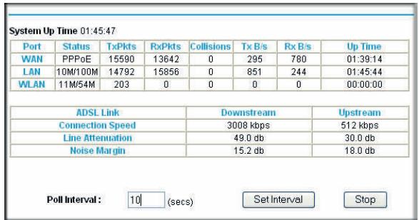
Figure 36.
The following table describes the N300 wireless modem router statistics.
| Item | Description | |
| System Up Time | The time elapsed since the N300 wireless modem router was last restarted. | |
| Port | The statistics for the WAN (Internet) and LAN (Ethernet) ports. For each port, the screen displays: | |
| Status | The link status of the port. | |
| TxPkts | The number of packets transmitted on this port since reset or manual clear. | |
| RxPkts | The number of packets received on this port since reset or manual clear. | |
| Collisions | The number of collisions on this port since reset or manual clear. | |
| Tx B/s | The current transmission (outbound) bandwidth used on the WAN and LAN ports. | |
| Rx B/s | The current reception (inbound) bandwidth used on the WAN and LAN ports. | |
| Up Time | The time elapsed since this port acquired the link. | |
| Poll Interval | The intervals at which the statistics are updated in this screen. | |
- To change the polling frequency, enter a time in seconds in the Poll Interval field, and click Set Interval.
- To stop the polling, click Stop.
Viewing a List of Attached Devices
The Attached Devices table lists all IP devices that the N300 wireless modem router has discovered on the local network. From the main menu, under Maintenance, select Attached Devices to view the table.
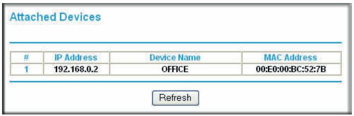
Figure 37.
For each device, the table shows the IP address, NetBIOS host name or device name (if available), and the Ethernet MAC address. To force the N300 wireless modem router to look for attached devices, click Refresh.
Note: If the N300 Wireless Modem Router is rebooted, the table data is lost until the N300 wireless modem router rediscovers the devices.
Managing the Configuration File
The configuration settings of the N300 wireless modem router are stored within the unit in a configuration file. You can back up (save) this file to your computer, restore it, or reset it to the factory default settings. From the main menu, select Maintenance > Backup Settings.
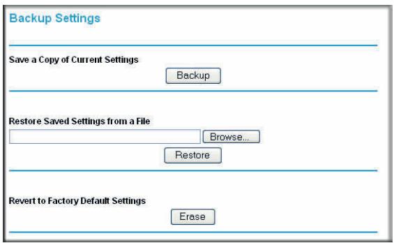
Figure 38.
The following sections describe the available options.
Backing Up and Restoring the Configuration
The Restore and Backup options in the Backup Settings screen let you save and retrieve a file containing your N300 wireless modem router's configuration settings.
To save your settings, click Backup. Your browser extracts the configuration file from the N300 wireless modem router and prompts you for a location on your computer to store the file. You can give the file a meaningful name at this time, such as cometc.cfg.
Tip: Before saving your configuration file, change the administrator password to the default, password. Then change it again after you have saved the configuration file. If you forget the password, you will need to reset the configuration to factory defaults.
To restore your settings from a saved configuration file, enter the full path to the file on your computer, or click Browse to browse to the file. When you have located it, click Restore to send the file to the N300 wireless modem router. The N300 wireless modem router then reboots automatically.

WARNING!
Do not interrupt the reboot process.
Erasing the Configuration
Under some circumstances (for example, if you move the N300 wireless modem router to a different network or if you have forgotten the password), you might want to erase the configuration and restore the factory default settings. After an erase, the N300 wireless modem router's user name is admin, the password is password, the LAN IP address is 192.168.0.1, and its DHCP server is enabled.
To erase the configuration, click the Erase button in the Backup Settings screen.
- To restore the factory default configuration settings when you do not know the login password or IP address, you must use the Restore Factory Settings button on the rear panel of the N300 wireless modem router (see Restoring the Factory Configuration Settings on page 147).
Running Diagnostic Utilities and Rebooting the Router
The N300 wireless modem router has a diagnostics feature. In the main menu, select Maintenance > Diagnostics to display the following screen:
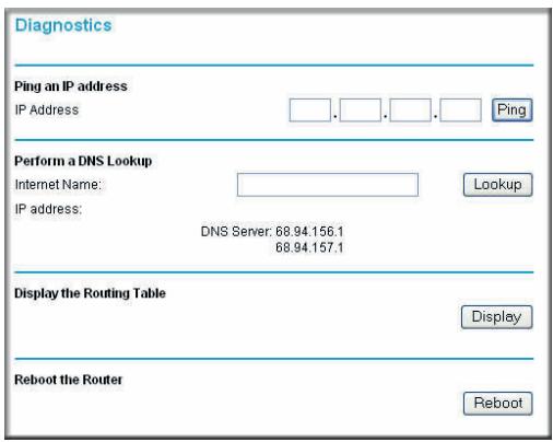
Figure 39.
You can use the Diagnostics screen to perform the following functions from the N300 wireless modem router:
- Ping an IP address to test connectivity to see if you can reach a remote host.
- Perform a DNS lookup to test if an Internet name resolves to an IP address to verify that the DNS server configuration is working.
- Display the Routing table to identify what other N300 wireless modem routers the N300 wireless modem router is communicating with.
Reboot the N300 wireless modem router to enable new network configurations to take effect or to clear problems with the N300 wireless modem router's network connection.
Enabling Remote Management Access
The remote management feature allows you to upgrade or check the status of your N300 wireless modem router through the Internet. From the main menu, select Advanced > Remote Management.
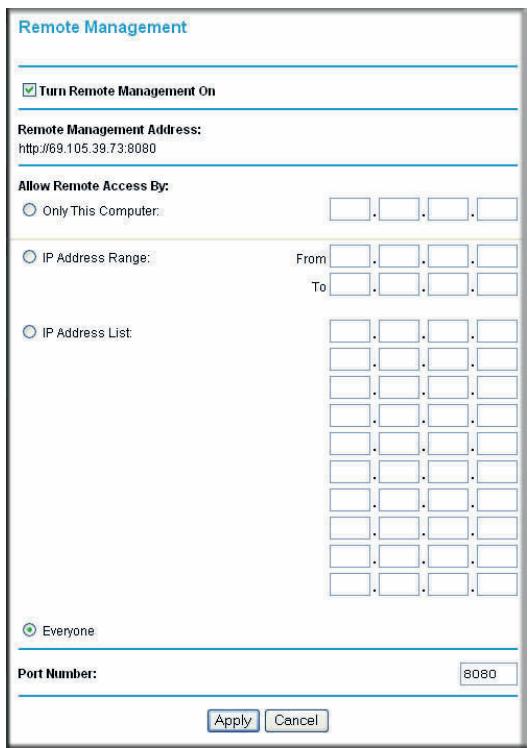
Figure 40.
Note: Be sure to change the N300 wireless modem router's default configuration password to a very secure password. The ideal password should contain no dictionary words from any language, and should be a mixture of letters (both uppercase and lowercase), numbers, and symbols. Your password can be up to 30 characters.
To configure your N300 wireless modem router for remote management:
- Select the Turn Remote Management On check box.
- Under Allow Remote Access By, specify what external IP addresses will be allowed to access the N300 wireless modem router's remote management.
Note: For enhanced security, restrict access to as few external IP addresses as practical.
- To allow access from any IP address on the Internet, select Everyone.
- To allow access from a range of IP addresses on the Internet, select IP Address Range.
Enter a beginning and ending IP address to define the allowed range.
-
To allow access from a single IP address on the Internet, select Only This Computer. Enter the IP address that will be allowed access.
-
Specify the port number for accessing the management interface.
Normal Web browser access uses the standard HTTP service port 80. For greater security, enter a custom port number for the remote management Web interface. Choose a number between 1024 and 65535, but do not use the number of any common service port. The default is 8080, which is a common alternate for HTTP.
- Click Apply to have your changes take effect.
Note: When accessing your N300 wireless modem router from the Internet, type your N300 wireless modem router's WAN IP address into your browser's address or location field, followed by a colon (:) and the custom port number. For example, if your external address is 134.177.0.123 and you use port number 8080, then enter http://134.177.0.123:8080 in your browser.
Traffic Meter
Traffic metering allows you to monitor the volume of Internet traffic passing through your router's Internet port. With the traffic meter utility, you can set limits for traffic volume, set a monthly limit, and get a live update of traffic usage.
To monitor traffic on your router:
- From the main menu, click Advanced > Traffic Meter.
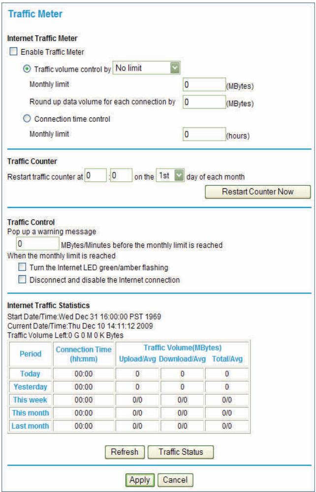
Figure 41.
a. To enable the traffic meter, select the Enable Traffic Meter check box.
-
If you would like to record and restrict the volume of Internet traffic, select the Traffic volume control by radio button. You can select one of the following options for controlling the traffic volume:
-
No Limit. No restriction is applied when the traffic limit is reached.
Download only. The restriction is applied to incoming traffic only. -
Both Directions. The restriction is applied to both incoming and outgoing traffic.
-
You can limit the amount of data traffic allowed per month:
-
By specifying how many Mbytes per month are allowed.
-
By specifying how many hours of traffic are allowed.
-
Under Traffic Counter, specify a specific time and date to restart the traffic counter.
-
Under Traffic Control, specify when to issue a warning message before the monthly limit of Mbytes or hours is reached. You can select one of the following to occur when the limit is attained:
The Internet LED flashes green.
-
The Internet connection is disconnected and disabled.
-
Under Internet Traffic Statistics, set up monitoring the data traffic.
- Click the Traffic Status button if you want a live update on Internet traffic status on your router.
- Click Apply to save your settings.
Network storage for sharing files and backing up data
This chapter describes how to access and configure a USB storage drive attached to your N300 wireless modem router.
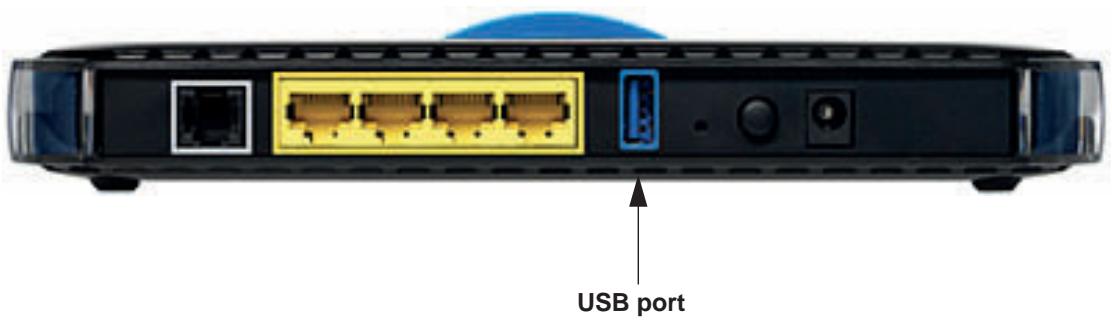
Figure 42.
Note: The USB port on the N300 wireless modem router can be used only to connect USB storage devices like flash drives or hard drives. Do not connect computers, USB modems, printers, CD drives, or DVD drives to the N300 wireless modem router USB port.
This chapter includes the following sections:
- USB Drive Requirements on page 65
- File Sharing Scenarios on page 65
- USB Storage Basic Settings on page 67
- Configuring USB Storage Advanced Settings on page 69
Media Server Settings on page 72 - Unmounting a USB Drive on page 72
- Specifying Approved USB Devices on page 72
- Connecting to the USB Drive from a Remote Computer on page 73
- Connecting to the USB Drive with Microsoft Network Settings on page 74
USB Drive Requirements
The N300 wireless modem router works with 1.0 and 1.1 (USB Full Speed) and 2.0 (USB High Speed) standards. The approximate USB bus speeds are shown in the following table.
| Bus | Speed/Second |
| USB 1.1 | 12 Mbits |
| USB 2.0 | 480 Mbits |
Actual bus speeds can vary, depending on the CPU speed, memory, speed of the network, and other variables.
The N300 wireless modem router should work with USB 2.0 or 1.1-compliant external flash and hard drives. For the most up-to-date list of USB drives supported by the N300 wireless modem router, go to:
http://kbserver.netgear.com/kb_web_files/n101300.asp
When selecting a USB device, bear in mind the following:
- The USB port on the N300 wireless modem router can be used with one USB hard drive at a time. Do not attempt to use a USB hub attached to the USB port.
- According to the USB 2.0 specification, the maximum available power is 5V @ 0.5A . Some USB devices might exceed this requirement, in which case the device might not function or might function erratically. Check the documentation for your USB device to be sure.
- The N300 wireless modem router supports FAT, FAT32, and NTFS (read only) file systems.
If your USB HD devices have an external power supply, be sure to use it.
File Sharing Scenarios
You can share files on the USB drive for a wide variety of business and recreational purposes. The files can be any PC, Mac, or Linux file type including text files, Word, PowerPoint, Excel, MP3, pictures, and multimedia. USB drive applications include:
- Sharing multimedia with friends and family—sharing MP3 files, pictures, and other multimedia with local and remote users.
- Sharing resources on your network—storing files in a central location so that you do not have to power up a computer to perform local sharing. In addition, you can share files between Macintosh, Linux, and PC computers by using the USB drive as a go-between the systems.
- Sharing files with offsite coworkers—sharing files such as Word documents, PowerPoint presentations, and text files with remote users. A few common uses are described in the following sections.
Sharing Photos with Friends and Family
You can create your own central storage location for photos and multimedia. This eliminates the need to log in to (and pay for) an external photo sharing site.
To share files with your friends and family:
- Insert the USB drive into the N300 wireless modem router USB port either directly or with a USB cable.
Computers on your local area network (LAN) can automatically access this USB drive using a Web browser or Microsoft Networking. - If you want to specify read only access, or to allow access from the Internet, see Configuring USB Storage Advanced Settings on page 69 for information.
Storing Files in a Central Location for Printing
This scenario is for a family that has one high-quality color printer directly attached to a PC, but not shared on the local area network (LAN). This family does not have a print server:
The daughter has some photos on her Macintosh computer that she wants to print.
- The mother has a photo-capable color printer directly attached to her PC, but not shared on the network.
The mother's and daughter's computers are not visible to each other on the network.
How can the daughter print her photos on the color printer attached to her mother's PC? This is where the USB drive on the N300 wireless modem router can save you time and effort.
- The daughter accesses the USB drive by typing \wreadyshare in the address field of her Web browser. Then she copies the photos to the USB drive.
- The mother uses a her Web browser or Microsoft Networking to transfer the files from the USB drive to the PC. Then she prints the files.
Sharing Large Files with Colleagues
Sending files that are larger than 5 MB can pose a problem for many email systems. The N300 wireless modem router allows you to share very large files such as PowerPoint presentations or .zip files with colleagues at another site. Rather than tying up their mail systems with large files, your colleagues can use FTP to easily download shared files from the N300 wireless modem router.
Sharing files with a remote colleague involves the following steps:
- To protect your network, set up appropriate security. Create a user name and password for the colleague with appropriate access.
- If you want to limit USB drive access to read only access, from the N300 wireless modem router USB Storage (Basic Settings) screen, click Edit a Network folder. In the Write Access field, select Edit, and then click Apply.
Note: The password for admin is the same one that you use to access the N300 wireless modem router. By default it is password.
- Enable FTP through the Internet in the USB Storage (Advanced Settings) screen. See Configuring USB Storage Advanced Settings on page 69.
USB Storage Basic Settings
You can view or edit basic settings for the USB storage device attached to your N300 wireless modem router. On the N300 wireless modem router main menu, select USB Storage > Basic Settings. The following screen displays:
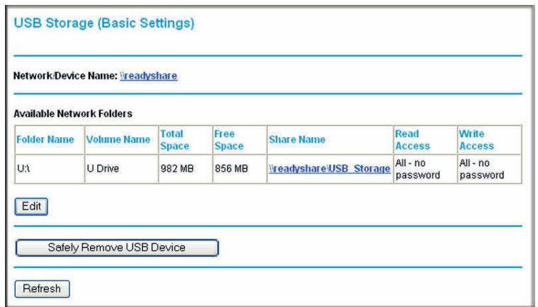
Figure 43.
By default, the USB storage device is available to all computers on your local area network (LAN). To access your USB device from this screen, you can click the network/device name or the share name.
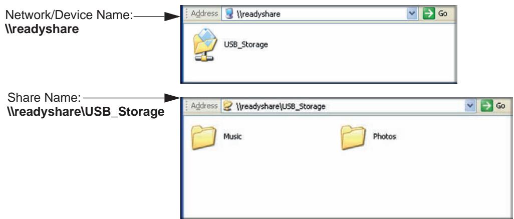
Figure 44.
You can also type \readyshare in the address field of your Web browser.
Note: If you logged in to the N300 wireless modem router before you connected your USB device, you might not see your USB device in the N300 wireless modem router screens until you log out and then log back in again.
The following table explains the fields and buttons in this screen.
| Fields and Buttons | Description | |
| Network Device Name | The default is \readyshare. This is the name used to access the USB device connected to the N300 wireless modem router. | |
| Available Network Folders | Folder Name | Full path of the used by the network folder. |
| Volume Name | Volume name from the storage device (either USB drive or HDD). | |
| Total/Free Space | Shows the current utilization of the storage device. | |
| Share Name | • You can click the name shown, or you can type it in the address field of your Web browser. • If Not Shared is shown, then the default share has been deleted and no other share for the root folder exists. Click the link to change this setting. | |
| Read/Write Access | • Shows the permissions and access controls on the network folder: • All - no password allows all users to access the network folder. • admin uses the same password that you use to log in to the N300 wireless modem router main menu. | |
| Edit button | You can click the Edit button to edit the Available Network Folders settings. See Editing a Network Folder on page 68. | |
| Safely Remove USB Device button | Click to safely remove the USB device attached to your N300 wireless modem router. See Unmounting a USB Drive on page 72. | |
Editing a Network Folder
This process is the same from either the USB Storage (Basic Settings) screen or the USB Storage (Advanced Settings) screen. Click the Edit button to open the Edit Network Folder screen:
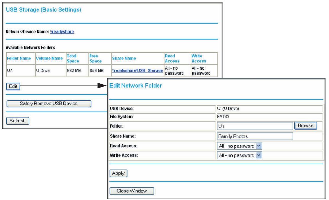
Figure 45.
You can use this screen to select a folder, to change the share name, or to change the read access or write access from All - no password to admin. The password for admin is the same one that is used to log in to the N300 wireless modem router main menu. By default it is password.
Note: You must click Apply in order for your changes to take effect.
Configuring USB Storage Advanced Settings
To configure advanced USB settings, from the main menu, select USB > Advanced Settings. The USB Storage (Advanced Settings) screen displays:
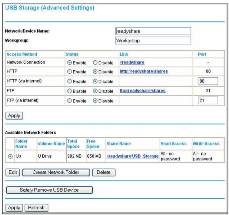
Figure 46.
You can use this screen to specify access to the USB storage device. The following table explains the fields and buttons in the USB Storage (Advanced Settings) screen.
| Fields | Description | |
| Network Device Name | The default is readyshare. This is the name used to access the USB device connected to the N300 wireless modem router from your computer. | |
| Workgroup | If you are using a Windows Workgroup rather than a domain, the workgroup name is displayed here. | |
| Access Method | Network Connection | Enabled by default, this allows all users on the LAN to have access to the USB drive. |
| HTTP | Disabled by default. If you enable this setting, you can type http://readyshare to access the USB drive. | |
| HTTP (via Internet) | Disabled by default. If you enable this settings, remote users can type http://readyshare to access the USB drive over the Internet. | |
| FTP | Disabled by default. | |
| FTP (via Internet) | Disabled by default. If you enable this settings, remote users can access the USB drive through FTP over the Internet. | |
| Available Network Folders | Folder Name | Full path of the used by the network folder. |
| Volume name | Volume name from the storage device (either USB drive or HDD). | |
| Total/Free Space | The current utilization of the storage device. | |
| Share Name | • You can click the name shown, or you can type it into the address field of your Web browser. • If Not Shared is shown, then the default share has been deleted and no other share for the root folder exists. Click the link to change this setting. | |
| Read/Write Access | • Shows the permissions and access controls on the network folder: • All - no password allows all users to access the network folder. • admin prompts you to enter the same password that you use to log in to the N300 wireless modem router main menu. | |
Creating a Network Folder
From the USB Storage (Advanced Settings) screen, click the Create a Network Folder button to open the Create Network Folder screen:
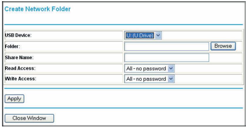
Figure 47.
You can use this screen to create a folder and to specify its share name, read access, and write access from All - no password to admin. The password for admin is the same one that is used to log in to the N300 wireless modem router main menu. By default it is password.
Note: You must click Apply in order for your changes to take effect.
Media Server Settings
You can set this modem router as a ReadyDLNA media server to enable the playback of videos, movies, and pictures on DLNA/UPnP AV-compliant media players such as the Xbox360, PlayStation, and NETGEAR's Digital Entertainer Live. ReadyDLNA means that this device serves media in DLNA-compatible form to DLNA/UPnP AV-compliant media players.
- From the main menu, select USB Storage > Media Server. The Media Server (Settings) screen displays.

- Select the Enable Media Server check box to enable this device to act as a media server. The name in the Media Server Name field is the name that shows up on media players.
- Under Content Scan, select Automatic for media files whenever new files are added to the ReadyShare USB storage. You can also schedule scans to run periodically, or click Scan Now to scan for new media immediately.
Unmounting a USB Drive

WARNING!
Unmount the USB drive first before physically unplugging it from the N300 wireless modem router. If the USB disk is removed or a cable is pulled while data is being written to the disk, it could result in file or disk corruption.
To unmount a USB disk drive so that no users can access it, from the USB Settings screen, click the Safely Remove USB Device button. This takes the drive offline.
Specifying Approved USB Devices
You can specify which USB devices are approved for use when connected to the N300 wireless modem router.
- From the main menu, select Advanced > USB Settings, and then click Approved Devices. The USB Drive Approved Settings screen displays:
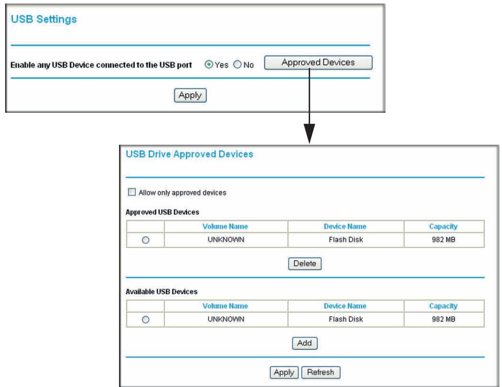
Figure 48.
- Select the USB device from the Available USB Devices list.
- Click Add.
- Select the Allow only approved devices check box.
- Click Apply so that your change goes into effect.
If you want to approve another USB device, you must first use the Safely Remove USB Device button to unmount the currently connected USB device. Connect the other USB device, and then repeat this process.
Connecting to the USB Drive from a Remote Computer
To connect to the USB drive from remote computers using a Web browser, you must use the router's Internet port IP address.
Locating the Internet Port IP Address
The Router Status screen shows the Internet port IP address:
- Log in to the N300 wireless modem router.
-
From the main menu, select Maintenance > Router Status.
-
Record the IP address that is listed for the Internet port. This is the IP address you can use to connect to the router remotely.
Accessing the Router's USB Drive Remotely Using FTP
You can connect to the router's USB drive using a Web browser:
- Connect to the router by typing ftp:// and the Internet port IP address in the address field of Internet Explorer or Netscape Navigator, for example:
ftp://10.1.65.4
If you are using Dynamic DNS, you can type the DNS name rather than the IP address.
- Type the account name and password that has access rights to the USB drive.
- The directories of the USB drive that your account has access to display, for example, share/partition1/directory1. You can now read and copy files from the USB directory.
Connecting to the USB Drive with Microsoft Network Settings
You can access the USB drive from local computers on your home or office network using Microsoft Network settings. You must be running Microsoft Windows 2000, XP, or older versions of Windows with Microsoft networking enabled. You can use normal Explorer operations such as drag and drop, file open, or cut and paste files from:
Microsoft Windows Start menu, Run option
- Windows Explorer
Network Neighborhood or My Network Places
Enabling File and Printer Sharing
Each computer's network properties must be set to enable network communication with the USB drive. File and Printer Sharing for Microsoft Networks must be enabled, as described in the following sections.
Note: In Windows 2000 and Windows XP, File and Printer Sharing is enabled by default.
Configuring Windows 98SE and Windows ME
The easiest way to get to your network properties is to go to your desktop, right-click Network Neighborhood and then click from the main menu.. File and Printer Sharing for Microsoft Network should be listed. If it is not, click Add and follow the installation prompts.
Note: If you have any questions about File and Printer Sharing, contact Microsoft for assistance.
Configuring Windows 2000 and Windows XP
Right-click the network connection for your local area network. File and Printer Sharing for Microsoft Networks should be listed. If it is not, click Install and follow the installation prompts.
Virtual Private Networking
Setting up secure encrypted communications
6
This chapter describes how to use the virtual private networking (VPN) features of the N300 wireless modem router. VPN communications paths are called tunnels. VPN tunnels provide secure, encrypted communications between your local network and a remote network or computer. See Appendix C, NETGEAR VPN Configuration, and click the link to Virtual Private Networking Basics on page 172 to learn more about VPNs.
This chapter is organized as follows:
- Overview of VPN Configuration on page 76
- Planning a VPN on page 78
VPN Tunnel Configuration on page 79 - Setting Up a Client-to-Gateway VPN Configuration on page 80
- Setting Up a Gateway-to-Gateway VPN Configuration on page 90
VPN Tunnel Control on page 94
Setting Up VPN Tunnels in Special Circumstances on page 100
Overview of VPN Configuration
Two common scenarios for VPN tunnels are between a remote PC and a network gateway, and between two or more network gateways. The N300 Wireless Dual Band ADSL2+ Modem Router DGND3300v2 supports both types. The N300 Wireless Dual Band ADSL2+ Modem Router DGND3300v2 supports up to five concurrent tunnels.
Client-to-Gateway VPN Tunnels
Client-to-gateway VPN tunnels provide secure access from a remote PC, such as a telecommuter connecting to an office network.
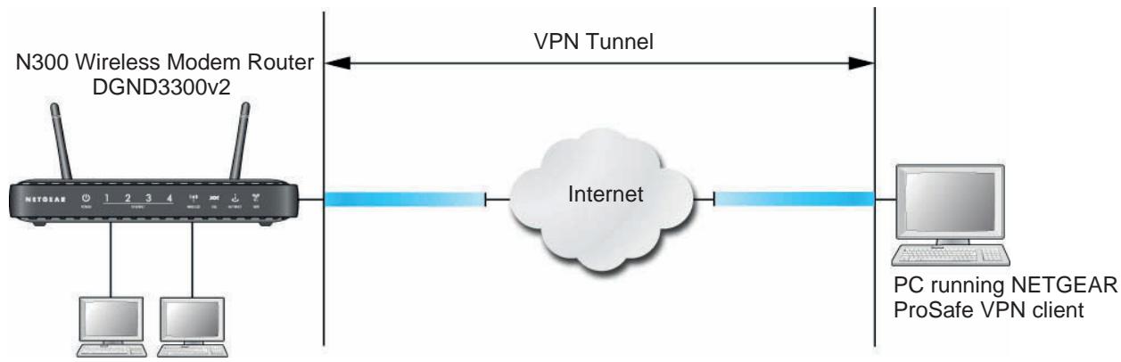
Figure 49. Telecommuter VPN Tunnel
A VPN client access allows a remote PC to connect to your network from any location on the Internet. The remote PC is one tunnel endpoint, running the VPN client software. The N300 wireless modem router on your network is the other tunnel endpoint. See Setting Up a Client-to-Gateway VPN Configuration on page 80 for information about how to set up this configuration.
Gateway-to-Gateway VPN Tunnels
Gateway-to-gateway VPN tunnels provide secure access between networks, such as a branch or home office and a main office.
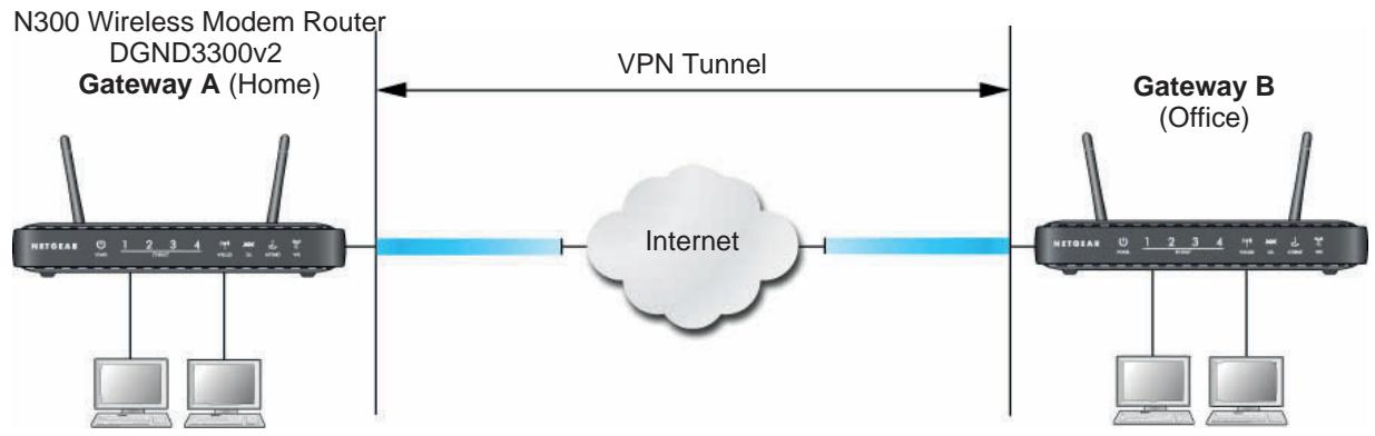
Figure 50. VPN Tunnel between Networks
A VPN between two or more NETGEAR VPN-enabled routers is a good way to connect branch or home offices and business partners over the Internet. VPN tunnels also enable access to network resources across the Internet. In this case, use gateways on each end of the tunnel to form the VPN tunnel end points. See Setting Up a Gateway-to-Gateway VPN Configuration on page 90 for information about how to set up this configuration.
Planning a VPN
When you set up a VPN, it is helpful to plan the network configuration and record the configuration parameters on a worksheet:
Table 1. VPN Tunnel Configuration Worksheet
| Parameter | Value to Be Entered | Field Selection | ||
| Connection Name | N/A | |||
| Pre-Shared Key | N/A | |||
| Secure Association | N/A | Main Mode | Manual Keys | |
| Perfect Forward Secrecy | N/A | Enabled | Disabled | |
| Encryption Protocol | N/A | DES | 3DES | |
| Authentication Protocol | N/A | MD5 | SHA-1 | |
| Diffie-Hellman (DH) Group | N/A | Group 1 | Group 2 | |
| Key Life in seconds | N/A | |||
| IKE Life Time in seconds | N/A | |||
| VPN Endpoint | Local IPSecID | LAN IP Address | Subnet Mask | FQDN or Gateway IP (WAN IP Address |
To set up a VPN connection, you must configure each endpoint with specific identification and connection information describing the other endpoint. You must configure the outbound VPN settings on one end to match the inbound VPN settings on other end, and vice versa.
This set of configuration information defines a security association (SA) between the two VPN endpoints. When planning your VPN, you must make a few choices first:
- Will the local end be any device on the LAN, a portion of the local network (as defined by a subnet or by a range of IP addresses), or a single PC?
- Will the remote end be any device on the remote LAN, a portion of the remote network (as defined by a subnet or by a range of IP addresses), or a single PC?
- Will either endpoint use fully qualified domain names (FQDNs)? FQDNs supplied by Dynamic DNS providers (see Using a Fully Qualified Domain Name (FQDN) on page 154) can allow a VPN endpoint with a dynamic IP address to initiate or respond to a tunnel request. Otherwise, the side using a dynamic IP address must always be the initiator.
-
Which method will you use to configure your VPN tunnels?
-
The VPN Wizard using VPNC defaults (see Table 2)
-
The typical automated Internet Key Exchange (IKE) setup (see Using Auto Policy to Configure VPN Tunnels on page 101)
- A manual keying setup in which you must specify each phase of the connection (see Using Manual Policy to Configure VPN Tunnels on page 109)
Table 2. Parameters Recommended by the VPNC and Used in the VPN Wizard
| Parameter | Factory Default Setting |
| Secure Association | Main Mode |
| Authentication Method | Pre-Shared Key |
| Encryption Method | 3DES |
| Authentication Protocol | SHA-1 |
| Diffie-Hellman (DH) Group | Group 2 (1024 bit) |
| Key Life | 8 hours |
| IKE Life Time | 1 hour |
What level of IPSec VPN encryption will you use?
- DES. The Data Encryption Standard (DES) processes input data that is 64 bits wide, encrypting these values using a 56-bit key. Faster but less secure than 3DES.
- 3DES. Triple DES achieves a higher level of security by encrypting the data three times using DES with three different, unrelated keys.
What level of authentication will you use?
- MDS. 128 bits, faster but less secure.
- SHA-1. 160 bits, slower but more secure.
VPN Tunnel Configuration
There are two tunnel configurations and three ways to configure them:
-
Use the VPN Wizard to configure a VPN tunnel (recommended for most situations):
-
See Setting Up a Client-to-Gateway VPN Configuration on page 80.
-
See Setting Up a Gateway-to-Gateway VPN Configuration on page 90.
-
See Using Auto Policy to Configure VPN Tunnels on page 101 when the VPN Wizard and its VPNC defaults (see Table 2 on page 79) are not appropriate for your special circumstances, but you want to automate the Internet Key Exchange (IKE) setup.
-
See Using Manual Policy to Configure VPN Tunnels on page 109 when the VPN Wizard and its VPNC defaults (see Table 2 on page 79) are not appropriate for your special circumstances and you must specify each phase of the connection. You manually enter all the authentication and key parameters. You have more control over the process; however, the process is more complex, and there are more opportunities for errors or
configuration mismatches between your N300 Wireless Dual Band ADSL2+ Modem Router DGND3300v2 and the corresponding VPN endpoint gateway or client workstation.
Setting Up a Client-to-Gateway VPN Configuration
Setting up a VPN between a remote PC running the NETGEAR ProSafe VPN client and a network gateway involves two steps, described in the following sections:
- Step 1: Configure the Client-to-Gateway VPN Tunnel on page 80 describes how to use the VPN Wizard to configure the VPN tunnel between the remote PC and network gateway.
- Step 2: Configure the NETGEAR ProSafe VPN Client on page 83 shows how to configure the NETGEAR ProSafe VPN client endpoint.
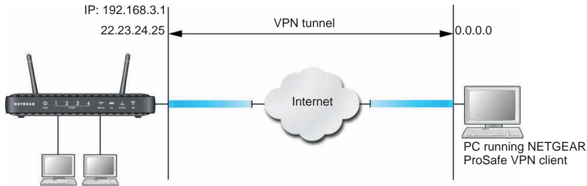
Figure 51. N300 Wireless Modem Router DGND3300v2 Client-to-Gateway VPN Tunnel
Step 1: Configure the Client-to-Gateway VPN Tunnel
This section describes using the VPN Wizard to set up the VPN tunnel using the VPNC default parameters listed in Table 2 on page 79. If you have special requirements not covered by these VPNC-recommended parameters, see Setting Up VPN Tunnels in Special Circumstances on page 100 for information about how to set up the VPN tunnel.
The following worksheet identifies the parameters used in this procedure. For a blank worksheet, see Planning a VPN on page 78.
Table 3. VPN Tunnel Configuration Worksheet
| Parameter | Value to Be Entered | Field Selection | |
| Connection Name | RoadWarrior | N/A | |
| Pre-Shared Key | 12345678 | N/A | |
| Secure Association | N/A | Main Mode | Manual Keys |
| Perfect Forward secrecy | N/A | Enabled | Disabled |
| Encryption Protocol | N/A | DES | 3DES |
Table 3. VPN Tunnel Configuration Worksheet
| Parameter | Value to Be Entered | Field Selection | ||
| Authentication Protocol | N/A | MD5 | SHA-1 | |
| Diffie-Hellman (DH) Group | N/A | Group 1 | Group 2 | |
| Key Life in seconds | 28800 (8 hours) | N/A | ||
| IKE Life Time in seconds | 3600 (1 hour) | N/A | ||
| VPN Endpoint | Local IPSecID | LAN IP Address | Subnet Mask | FQDN or Gateway IP (WAN IP Address) |
| Client | toGateway | N/A | N/A | Dynamic |
| Gateway | toClient | 192.168.3.1 | 255.255.255.0 | 22.23.24.25 |
To configure a client-to-gateway VPN tunnel using the VPN Wizard:
- Log in to the N300 wireless modem router. On the main menu under Advanced - VPN, select VPN Wizard.
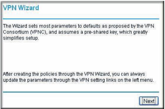
- Click Next to proceed.
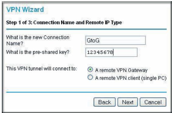
- Fill in the Connection Name and pre-shared key fields.
The connection name is for convenience and does not affect how the VPN tunnel functions.
- Select the radio button for the type of target end point, and click Next.

- Enter the remote IP address, and click Next.
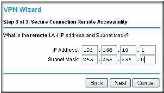
The Summary screen displays:
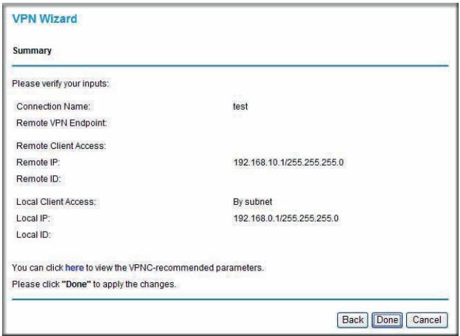
Note: To view the VPNC-recommended authentication and encryption settings used by the VPN Wizard, click the here link.
- Click Done on the Summary screen. The VPN Policies screen displays, showing that the new tunnel is enabled:
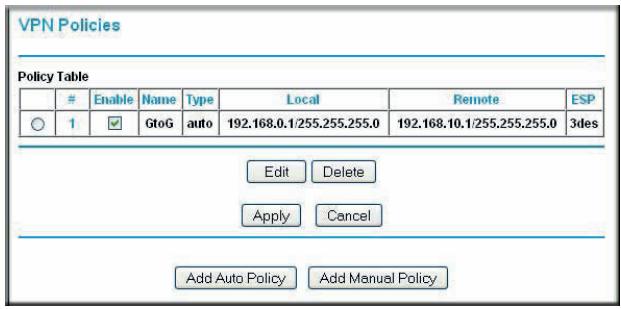
To view or modify the tunnel settings, select its radio button and click Edit.
Note: See Using Auto Policy to Configure VPN Tunnels on page 101 for information about how to enable the IKE keep-alive capability on an existing VPN tunnel.
Step 2: Configure the NETGEAR ProSafe VPN Client
This section describes how to configure the NETGEAR ProSafe VPN client on a remote PC. These instructions assume that the PC running the client has a dynamically assigned IP address.
The PC must have the NETGEAR ProSafe VPN Client program installed that supports IPSec. Go to the NETGEAR website (http://www.netgear.com) for information about how to purchase the NETGEAR ProSafe VPN Client.
Note: Before installing the NETGEAR ProSafe VPN Client software, be sure to turn off any virus protection or firewall software you might be running on your PC. You might need to insert your Windows CD to complete the installation.
- Install the NETGEAR ProSafe VPN client on the remote PC, and then reboot.
a. Install the IPSec component. You might have the option to install either the VPN adapter or the IPSec component or both. The VPN adapter is not necessary.
If you do not have a modem or dial-up adapter installed in your PC, you might see the warning message stating "The NETGEAR ProSafe VPN Component requires at least one dial-up adapter be installed." You can disregard this message.
b. Reboot the remote PC.
The ProSafe icon (S) is in the system tray.
c. Double-click the ProSafe icon to open the Security Policy Editor.
- Add a new connection.
a. Run the NETGEAR ProSafe Security Policy Editor program, and, using the Table 3 on page 80, create a VPN connection.
b. From the Edit menu of the Security Policy Editor, select Add, and then click Connection.
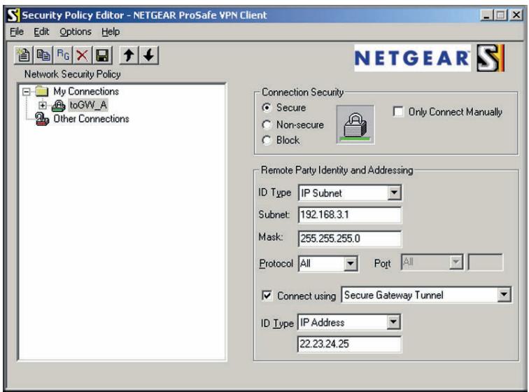
A New Connection listing appears in the list of policies.
c. Rename the new connection so that it matches the Connection Name field in the VPN Settings screen of the N300 wireless modem router on LAN A. Choose connection names that make sense to the people using and administering the VPN.
Note: In this example, the connection name used on the client side of the VPN tunnel is togw_a, and it does not have to match the RoadWarrior connection name used on the gateway side of the VPN tunnel because connection names are irrelevant to how the VPN tunnel functions.
d. Enter the following settings:
- Connection Security. Select Secure.
ID Type. Select IP Subnet. - Subnet. In this example, type 192.168.3.1 as the network address of the N300 wireless modem router.
- Mask. Enter 255.255.255.0 as the LAN subnet mask of the N300 wireless modem router.
- Protocol. Select All to allow all traffic through the VPN tunnel.
e. Select the Connect using Secure Gateway Tunnel check box.
f. In the ID Type drop-down list, select IP Address.
g. Enter the public WAN IP address of the N300 wireless modem router in the field directly below the ID Type drop-down list. In this example, 22.23.24.25 is used.
The resulting connection settings are shown in Figure 52 on page 85.
- Configure the security policy in the NETGEAR ProSafe VPN Client software:
a. In the Network Security Policy list, expand the new connection by double-clicking its name or clicking the + symbol. My Identity and Security Policy subheadings appear below the connection name.
b. Click the Security Policy subheading to view the Security Policy settings.
Figure 52. Security Policy settings, Client-to-Gateway A
c. In the Select Phase 1 Negotiation Mode section of the screen, select the Main Mode radio button.
- Configure the VPN client identity.
In this step, you provide information about the remote VPN client PC. You must provide the pre-shared key that you configured in the N300 wireless modem router and either a fixed IP address or a fixed virtual IP address of the VPN client PC.
a. In the Network Security Policy list on the left side of the Security Policy Editor window, click My Identity.
b. In the Select Certificate drop-down list, select None.
c. In the ID Type drop-down list, select IP Address. If you are using a virtual fixed IP address, enter this address in the Internal Network IP Address field. Otherwise, leave this field empty.
d. In the Internet Interface section of the screen, select the adapter that you use to access the Internet. If you have a dial-up Internet account, select PPP Adapter in the Name list. If you have a dedicated cable or DSL line, select your Ethernet adapter. If you will be switching between adapters or if you have only one adapter, select Any.
e. In the My Identity section of the screen, click the Pre-Shared Key button. The Pre-Shared Key screen displays:
f. Click Enter Key. Enter the N300 wireless modem router pre-shared key, and then click OK. In this example, 12345678 is entered, though asterisks are displayed in the field. This field is case-sensitive.
- Configure the VPN client authentication proposal.
In this step, you provide the type of encryption (DES or 3DES) to be used for this connection. This selection must match your selection in the N300 wireless modem router configuration.
a. In the Network Security Policy list on the left side of the Security Policy Editor window, expand the Security Policy heading by double-clicking its name or clicking the + symbol.
b. Expand the Authentication subheading by double-clicking its name or clicking the + symbol. Then select Proposal 1 below Authentication.
c. In the Authentication Method drop-down list, select Pre-Shared key.
d. In the Encrypt Alg drop-down list, select the type of encryption that is configured for the encryption protocol in the N300 wireless modem router, as listed in Table 1 on page 78. This example uses Triple DES.
e. In the Hash Alg drop-down list, select SHA-1.
f. In the SA Life drop-down list, select Unspecified.
g. In the Key Group drop-down list, select Diffie-Hellman Group 2.
- Configure the VPN client key exchange proposal.
In this step, you provide the type of encryption (DES or 3DES) to be used for this connection. This selection must match your selection in the N300 wireless modem router configuration.
a. Expand the Key Exchange subheading by double-clicking its name or clicking the + symbol. Then select Proposal 1 below Key Exchange.
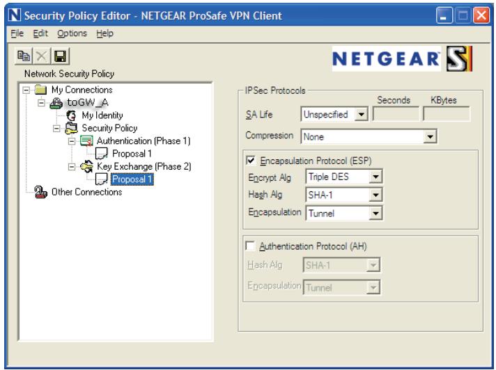
b. In the SA Life drop-down list, select Unspecified.
c. In the Compression drop-down list, select None.
d. Select the Encapsulation Protocol (ESP) check box.
e. In the Encrypt Alg drop-down list, select the type of encryption that is configured for the encryption protocol in the N300 wireless modem router, as listed in Table 1 on page 78. This example uses Triple DES.
f. In the Hash Alg drop-down list, select SHA-1.
g. In the Encapsulation drop-down list, select Tunnel.
h. Leave the Authentication Protocol (AH) check box cleared.
- Save the VPN client settings.
In the Security Policy Editor window, select File > Save.
After you have configured and saved the VPN client information, your PC automatically opens the VPN connection when you attempt to access any IP addresses in the range of the remote VPN router's LAN.
- Check the VPN connection.
To check the VPN connection, you can initiate a request from the remote PC to the N300 wireless modem router's network by using the Connect option in the NETGEAR ProSafe menu bar. The NETGEAR ProSafe client reports the results of the attempt to connect. Since the remote PC has a dynamically assigned WAN IP address, it must initiate the request.
To perform a ping test using our example, start from the remote PC:
a. Establish an Internet connection from the PC.
b. On the Windows taskbar, click the Start button, and then select Run.
c. Type ping -t 192.168.3.1, and then click OK.
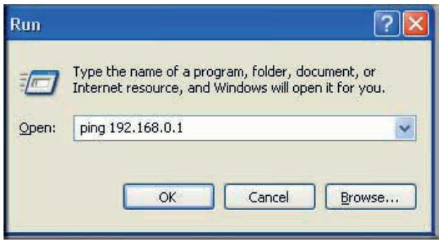
This causes a continuous ping to be sent to the first N300 wireless modem router. After between several seconds and 2 minutes, the ping response should change from timed out to reply.
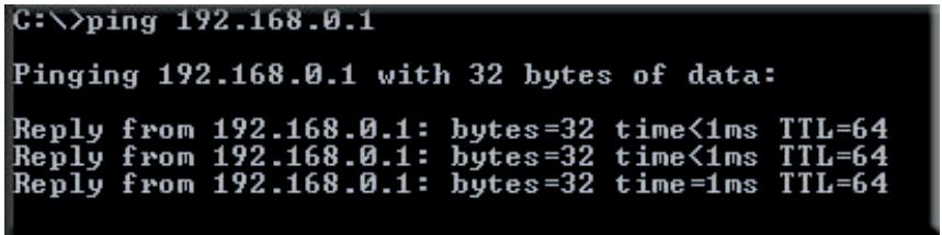
Once the connection is established, you can open a browser on the PC and enter the LAN IP address of the remote gateway. After a short wait, you should see the login screen of the N300 wireless modem router (unless another PC is already logged in to the N300 wireless modem router).
You can view information about the progress and status of the VPN client connection by opening the NETGEAR ProSafe Log Viewer.
To launch this function, click the Windows Start button, then select Programs > NETGEAR ProSafe VPN Client > Log Viewer. The Log Viewer screen for a successful connection is shown in the following figure:
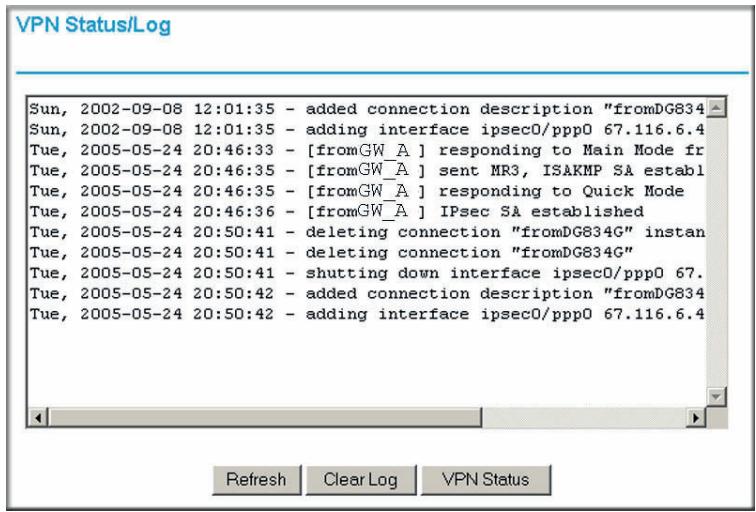
Note: Use the active VPN tunnel information and pings to determine whether a failed connection is due to the VPN tunnel or some reason outside the VPN tunnel.
- The Connection Monitor screen for this connection is shown in the following figure:
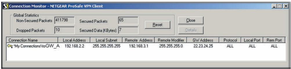
In this example you can see these settings:
- The N300 wireless modem router has a GW address (public IP WAN address) of 22.23.24.25.
The N300 wireless modem router has a remote address (LAN IP address) of 192.168.3.1. - The VPN client PC has a local address (dynamically assigned address) of 192.168.2.2.
While the connection is being established, the Connection Name field in this screen displays SA before the name of the connection. When the connection is successful, the SA changes to the yellow key symbol shown in the previous figure.
Note: While your PC is connected to a remote LAN through a VPN, you might not have normal Internet access. If this is the case, you must close the VPN connection to have normal Internet access.
Setting Up a Gateway-to-Gateway VPN Configuration
Note: This section describes how to use the VPN Wizard to set up the VPN tunnel using the VPNC default parameters listed in Table 2 on page 79. If you have special requirements not covered by these VPNC-recommended parameters, see Setting Up VPN Tunnels in Special Circumstances on page 100 for information about how to set up the VPN tunnel.
Follow this procedure to configure a gateway-to-gateway VPN tunnel using the VPN Wizard.
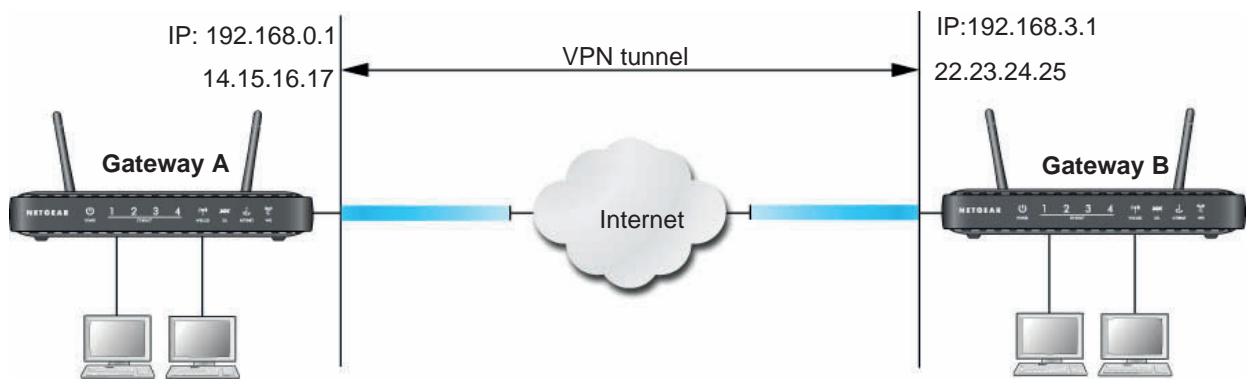
Figure 53. Gateway-to-Gateway VPN Tunnel
Set the LAN IPs on each N300 wireless modem router to different subnets and configure each correctly for the Internet. The subsequent examples assume the settings shown in the following table.
Table 4. Gateway-to-Gateway VPN Tunnel Configuration Worksheet
| Parameter | Value to Be Entered | Field Selection | ||
| Connection Name | GtoGr | N/A | ||
| Pre-Shared Key | 12345678 | N/A | ||
| Secure Association | N/A | Main Mode | Manual Keys | |
| Perfect Forward Secrecy | N/A | Enabled | Disabled | |
| Encryption Protocol | N/A | DES | 3DES | |
| Authentication Protocol | N/A | MD5 | SHA-1 | |
| Diffie-Hellman (DH) Group | N/A | Group 1 | Group 2 | |
| Key Life in seconds | 28800 (8 hours) | N/A | ||
| IKE Life Time in seconds | 3600 (1 hour) | N/A | ||
| VPN Endpoint | Local IPSecID | LAN IP Address | Subnet Mask | FQDN or Gateway IP (WAN IP Address) |
| Gateway_A | GW_A | 192.168.0.1 | 255.255.255.0 | 14.15.16.17 |
| Gateway_B | GW_B | 192.168.3.1 | 255.255.255.0 | 22.23.24.25 |
Note: The LAN IP address ranges of each VPN endpoint must be different. The connection will fail if both are using the NETGEAR default address range of 192.168.0.x.
To configure a gateway-to-gateway VPN tunnel using the VPN Wizard:
- Log in to Gateway A on LAN A. From the main menu, select VPN Wizard. Click Next, and the Step 1 of 3 screen displays.
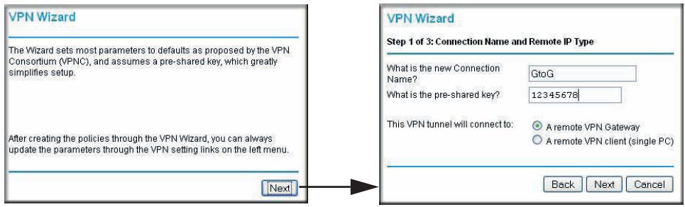
- Fill in the Connection Name and pre-shared key fields. Select the radio button for the type of target end point, and click Next, and the Step 2 of 3 screen displays.
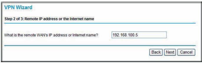
- Fill in the IP address or FQDN for the target VPN endpoint WAN connection, and click Next. and the Step 3 of 3 screen displays.
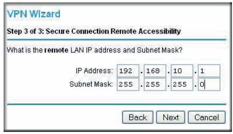
- Fill in the IP Address and Subnet Mask fields for the target endpoint that can use this tunnel, and click Next.
The VPN Wizard Summary screen displays:
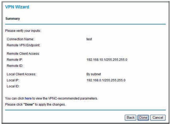
To view the VPNC-recommended authentication and encryption settings used by the VPN Wizard, click the here link.
- Click Done on the Summary screen.
The VPN Policies screen displays, showing that the new tunnel is enabled.
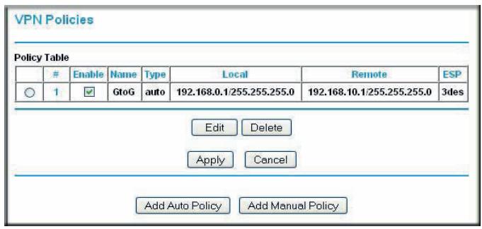
Note: See Using Auto Policy to Configure VPN Tunnels on page 101 for information about how to enable the IKE keep-alive capability on an existing VPN tunnel.
-
Repeat these steps for the gateway on LAN B, and pay special attention to the following network settings:
-
WAN IP of the remote VPN gateway (for example, 14.15.16.17)
-
LAN IP settings of the remote VPN gateway:
-
IP address (for example, 192.168.0.1)
- Subnet mask (for example, 255.255.255.0)
-
Pre-shared key (for example, 12345678)
-
Use the VPN Status screen to activate the VPN tunnel by performing the following steps:
Note: The VPN Status screen is only one of three ways to active a VPN tunnel. See Activating a VPN Tunnel on page 94 for information about the other ways.
a. On the N300 wireless modem router menu, select VPN Status. The VPN Status/Log screen displays:
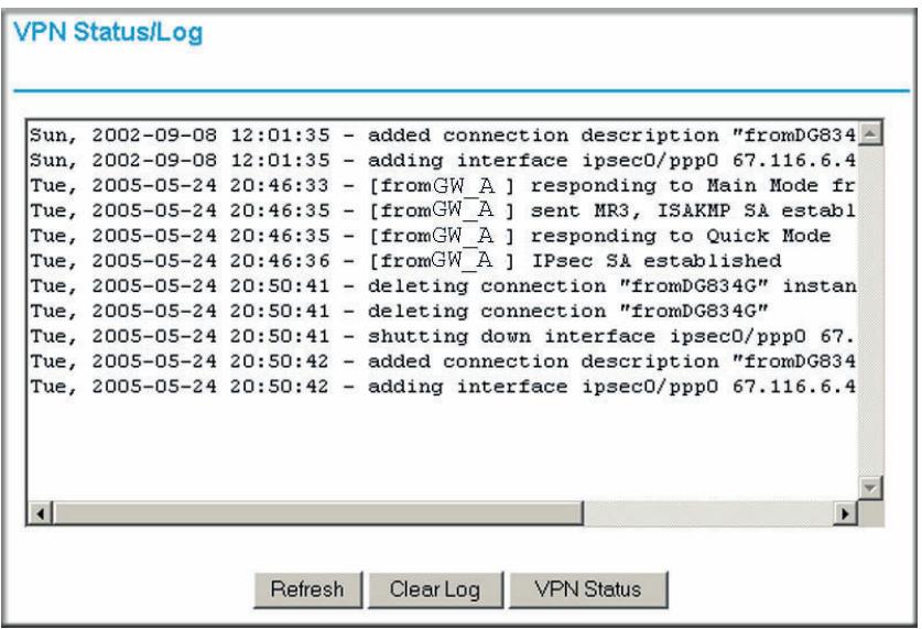
b. Click the VPN Status button to display the Current VPN Tunnels (SAs) screen:
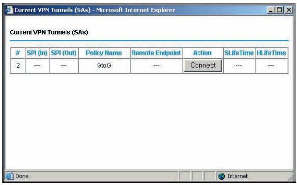
c. Click Connect for the VPN tunnel you want to activate. View the VPN Status/Log screen to verify that the tunnel is connected.
VPN Tunnel Control
Activating a VPN Tunnel
There are three ways to activate a VPN tunnel:
- Use the VPN Status screen.
- Activate the VPN tunnel by pinging the remote endpoint.
- Start using the VPN tunnel.
Note: See Using Auto Policy to Configure VPN Tunnels on page 101 for information about how to enable the IKE keep-alive capability on an existing VPN tunnel.
Using the VPN Status Screen to Activate a VPN Tunnel
To use the VPN Status screen to activate a VPN tunnel:
- Log in to the N300 wireless modem router.
- On the main menu, select VPN Status. The VPN Status/Log screen displays:
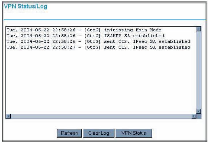
- Click VPN Status to display the Current VPN Tunnels (SAs) screen:
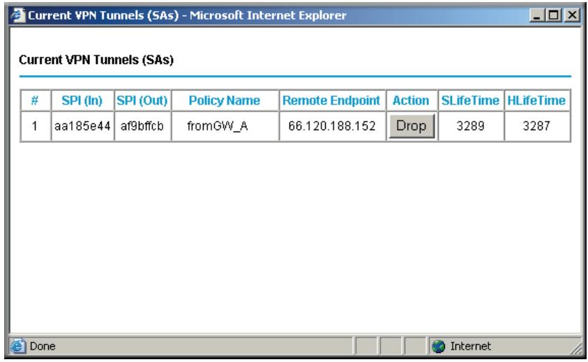
- Click Connect for the VPN tunnel that you want to activate.
Activating the VPN Tunnel by Pinging the Remote Endpoint
Note: This section uses 192.168.3.1 for a sample remote endpoint LAN IP address.
To activate the VPN tunnel by pinging the remote endpoint (for example, 192.168.3.1), perform the following steps depending on whether your configuration is client-to-gateway or gateway-to-gateway:
- Client-to-gateway configuration. To check the VPN connection, you can initiate a request from the remote PC to the N300 Wireless Dual Band ADSL2+ Modem Router DGND3300v2's network by using the Connect option in the NETGEAR ProSafe menu bar. The NETGEAR ProSafe client reports the results of the attempt to connect. Since the remote PC has a dynamically assigned WAN IP address, it must initiate the request.
To perform a ping test using our example, start from the remote PC:
a. Establish an Internet connection from the PC.
b. On the Windows taskbar, click the Start button, and then select Run.
c. Type ping -t 192.168.3.1, and then click OK.
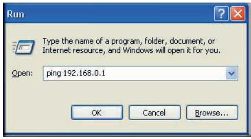
Running a ping test to the LAN from the PC
This causes a continuous ping to be sent to the first N300 Wireless Dual Band ADSL2+ Modem Router DGND3300v2. Within 2 minutes, the ping response should change from timed out to reply.
Note: You can use Ctrl-C to stop the pinging.
C:\>ping 192.168.0.1
Pinging 192.168.0.1 with 32 bytes of data:
Reply from 192.168.0.1: bytes=32 time<1ms TTL=64
Reply from 192.168.0.1: bytes=32 time<1ms TTL=64
Reply from 192.168.0.1: bytes=32 time=1ms TTL=64
Once the connection is established, you can open a browser on the PC and enter the LAN IP address of the remote N300 Wireless Dual Band ADSL2+ Modem Router DGND3300v2. After a short wait, you should see the login screen of the N300 wireless modem router (unless another PC already has the N300 Wireless Dual Band ADSL2+ Modem Router DGND3300v2 management interface open).
- Gateway-to-gateway configuration. Test the VPN tunnel by pinging the remote network from a PC attached to Gateway A (the N300 wireless modem router).
a. Open a command prompt (for example, Start > Run > cmd).
b. Type ping 192.168.3.1.
Pinging 192.168.3.1 with 32 bytes of data: Reply from 192.168.3.1: bytes=32 time=20ms TTL=254 Reply from 192.168.3.1: bytes=32 time=10ms TTL=254 Reply from 192.168.3.1: bytes=32 time=20ms TTL=254
Note: The pings might fail the first time. If they do, then try the pings a second time.
Start Using a VPN Tunnel to Activate It
To use a VPN tunnel, use a Web browser to go to a URL whose IP address or range is covered by the policy for that VPN tunnel.
Verifying the Status of a VPN Tunnel
To use the VPN Status screen to determine the status of a VPN tunnel:
- Log in to the N300 wireless modem router.
- On the main menu, select VPN Status to display the VPN Status/Log screen.
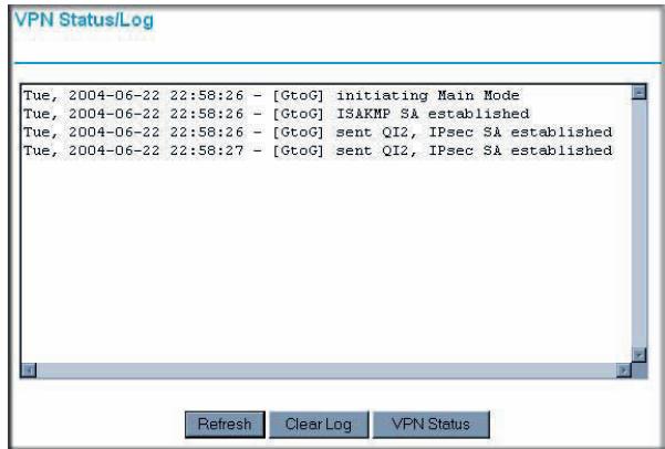
This log shows the details of recent VPN activity, including the building of the VPN tunnel. If there is a problem with the VPN tunnel, refer to the log for information about what might be the cause of the problem.
- Click Refresh to see the most recent entries.
-
Click Clear Log to delete all log entries.
-
On the VPN Status/Log screen, click VPN Status to display the Current VPN Tunnels (SAs) screen.
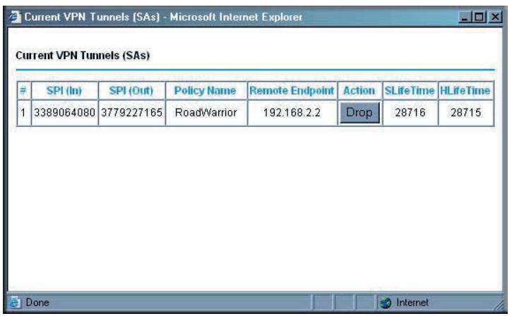
This table lists the following data for each active VPN tunnel.
- SPI. Each SA has a unique SPI (Security Parameter Index) for traffic in each direction. For manual key exchange, the SPI is specified in the policy definition. For automatic key exchange, the SPI is generated by the IKE protocol.
Policy Name. The VPN policy associated with this SA. - Remote Endpoint. The IP address on the remote VPN endpoint.
Action. Either a Drop or a Connect button. - SLifeTime (Secs). The remaining soft lifetime for this SA in seconds. When the soft lifetime becomes 0 (zero), the SA (security association) is renegotiated.
- HLifeTime (Secs). The remaining hard lifetime for this SA in seconds. When the hard lifetime becomes 0 (zero), the SA (security association) is terminated. (It is reestablished if required.)
Deactivating a VPN Tunnel
Sometimes a VPN tunnel must be deactivated for testing purposes. You can deactivate a VPN tunnel from two places:
Policy table on VPN Policies screen
VPN Status screen
Using the Policy Table on the VPN Policies Screen to Deactivate a VPN Tunnel To use the VPN Policies screen to deactivate a VPN tunnel:
- Log in to the N300 wireless modem router.
- On the main menu, select VPN Policies to display the VPN Policies screen.

- In the Policy Table, clear the Enable check box for the VPN tunnel that you want to deactivate, and then click Apply. (To reactivate the tunnel, select the Enable check box, and then click Apply.)
Using the VPN Status Screen to Deactivate a VPN Tunnel
To use the VPN Status screen to deactivate a VPN tunnel:
- Log in to the N300 wireless modem router.
- On the main menu, select VPN Policies to display the VPN Policies screen.

- Click VPN Status. The Current VPN Tunnels (SAs) screen displays:
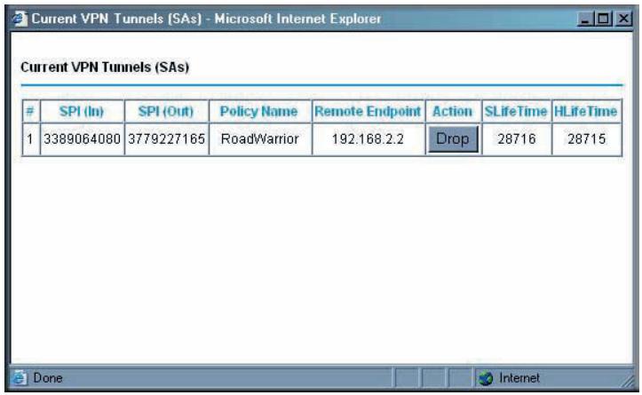
- Click Drop for the VPN tunnel that you want to deactivate.
Deleting a VPN Tunnel
To delete a VPN tunnel:
- Log in to the N300 wireless modem router.
- On the main menu, select VPN Policies to display the VPN Policies screen. In the Policy Table, select the radio button for the VPN tunnel to be deleted, and then click Delete.
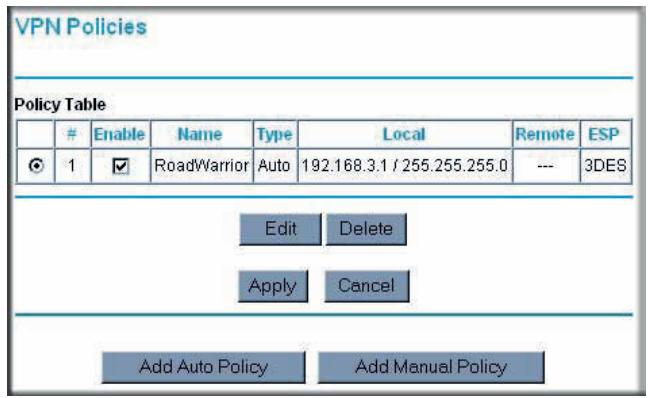
Setting Up VPN Tunnels in Special Circumstances
When the VPN Wizard and its VPNC defaults (see Table 2 on page 79) are not appropriate for your circumstances, use one of these alternatives:
-
Auto Policy. For a typical automated Internet Key Exchange (IKE) setup, see Using Auto Policy to Configure VPN Tunnels on page 101. Auto Policy uses the IKE protocol to define the authentication scheme and automatically generate the encryption keys.
-
Manual Policy. For a manual keying setup in which you must specify each phase of the connection, see Using Manual Policy to Configure VPN Tunnels on page 109. Manual policy does not use IKE. Rather, you manually enter all the authentication and key parameters. You have more control over the process; however, the process is more complex, and there are more opportunities for errors or configuration mismatches between your N300 Wireless Dual Band ADSL2+ Modem Router DGND3300v2 and the corresponding VPN endpoint gateway or client workstation.
Using Auto Policy to Configure VPN Tunnels
You need to configure matching VPN settings on both VPN endpoints. The outbound VPN settings on one end must match to the inbound VPN settings on other end, and vice versa.
For an example of using Auto Policy, see Example of Using Auto Policy on page 106.
Configuring VPN Network Connection Parameters
All VPN tunnels on the N300 wireless modem router require that you configure several network parameters. This section describes those parameters and how to access them.
The most common configuration scenarios use IKE to manage the authentication and encryption keys. The IKE protocol performs negotiations between the two VPN endpoints to automatically generate and update the required encryption parameters.
From the main menu, select VPN Policies, and then click the Add Auto Policy button to display the VPN - Auto Policy screen:
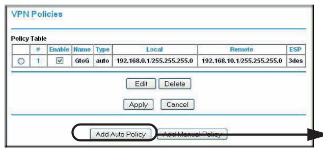
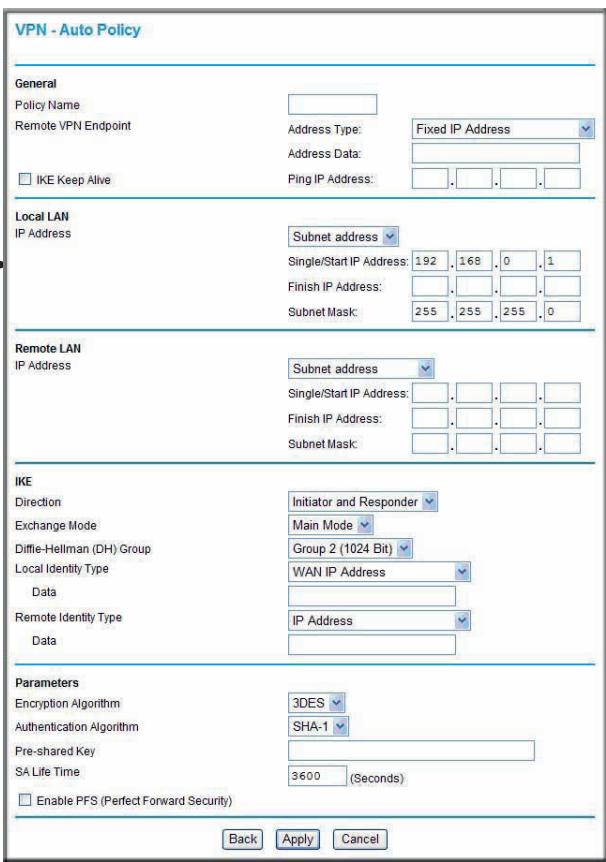
The DGND3300v2 VPN tunnel network connection fields are defined in the following table.
Table 5. VPN - Auto Policy Screen Settings
| Fields and Settings | Description | |
| General | Policy Name | Enter a unique name. This name is not supplied to the remote VPN endpoint. It is used only to help you manage the policies. |
| Remote VPN Endpoint | ·The remote VPN endpoint must have this VPN's gateway address entered as its remote VPN endpoint. ·If the remote endpoint has a dynamic IP address, select Dynamic IP Address. No address data input is required. You can set up multiple remote dynamic IP policies, but only one such policy can be enabled at a time. Otherwise, select an option (IP address or domain name) and enter the address of the remote VPN endpoint to which you want to connect. | |
| IKE Keep Alive | ·If you want to ensure that a connection is kept open, or, if that is not possible, that it is quickly reestablished when disconnected, select this check box. ·The ping IP address must be associated with the remote endpoint. The remote LAN address must be used. This IP address will be pinged periodically to generate traffic for the VPN tunnel. The remote keep-alive IP address must be covered by the remote LAN IP range and must correspond to a device that can respond to ping. The range should be made as narrow as possible to meet this objective. | |
| Local LAN | Subnet Mask | The network mask. |
| The remote VPN endpoint must have these IP addresses entered as its remote addresses. | Single/Start IP Address | ·Enter the IP address for a single address, or the starting address for an address range. A single address setting is used when you want to make a single server on your LAN available to remote users. A range must be an address range used on your LAN. ·Any. The remote VPN endpoint can be at any IP address. |
| Finish IP Address | For an address range, enter the finish IP address. This must be an address range used on your LAN. | |
| Remote LAN | IP Address | Single PC - no Subnet. Select this option if there is no LAN (only a single PC) at the remote endpoint. If this option is selected, no additional data is required. The typical application is a PC running the VPN client at the remote end. |
| The remote VPN endpoint must have these IP addresses entered as its local addresses. | Single/Start IP Address | ·Enter an IP address that is on the remote LAN. You can use this setting when you want to access a server on the remote LAN. ·For a range of addresses, enter the starting IP address. This must be an address range used on the remote LAN. ·Any. Any outgoing traffic from the computers in the Local IP fields triggers an attempted VPN connection to the remote VPN endpoint. Be sure you want this option before selecting it. |
| Finish IP Address | Enter the finish IP address for a range of addresses. This must be an address range used on the remote LAN. | |
| Subnet Mask | Enter the network mask. | |
| IKE | Direction | This setting is used when the router determines if the IKE policy matches the current traffic. Select an option. ·Responder only. Incoming connections are allowed, but outgoing connections are blocked. ·Initiator andResponder. Both incoming and outgoing connections are allowed. |
| Exchange Mode | Ensure that the remote VPN endpoint is set to use Main Mode. | |
| Diffie-Hellman (DH) Group | The Diffie-Hellman algorithm is used when keys are exchanged. The DH Group setting determines the bit size used in the exchange. This value must match the value used on the remote VPN gateway. | |
| Local Identity Type | Select an option to match the Remote Identity Type setting on the remote VPN endpoint. ·WAN IP Address. Your Internet IP address. ·Fully Qualified Domain Name. Your domain name. ·Fully Qualified User Name. Your name, email address, or other ID. | |
| Local Identity Data | Enter the data for the local identity type that you selected. (If WAN IP Address is selected, no input is required.) | |
| Remote Identity Type | Select the option that matches the Local Identity Type setting on the remote VPN endpoint. ·IP Address. The Internet IP address of the remote VPN endpoint. ·Fully Qualified Domain Name. The domain name of the remote VPN endpoint. ·Fully Qualified User Name. The name, email address, or other ID of the remote VPN endpoint. | |
| Remote Identity Data | Enter the data for the remote identity type that you selected. If IP Address is selected, no input is required. | |
| Parameters | Encryption Algorithm | The encryption algorithm used for both IKE and IPSec. This setting must match the setting used on the remote VPN gateway. DES and 3DES are supported. ·DES. The Data Encryption Standard (DES) processes input data that is 64 bits wide, encrypting these values using a 56-bit key. Faster but less secure than 3DES. ·3DES. (Triple DES) achieves a higher level of security by encrypting the data three times using DES with three different, unrelated keys. |
| Authentication Algorithm | The authentication algorithm used for both IKE and IPSec. This setting must match the setting used on the remote VPN gateway. Auto, MD5, and SHA-1 are supported. Auto negotiates with the remote VPN endpoint and is not available in responder-only mode. ·MD5. 128 bits, faster but less secure. ·SHA-1. 160 bits, slower but more secure. This is the default. | |
| Pre-shared Key | The key must be entered both here and on the remote VPN gateway. | |
| Parameters(Continued) | SA Life Time | The time interval before the SA (security association) expires. (It is automatically reestablished as required.) While using a short time period (or data amount) increases security, it also degrades performance. It is common to use periods over an hour (3600 seconds) for the SA life-time. This setting applies to both IKE and IPSec SAs. |
| Enable IPSec PFS(Perfect Forward Secrecy) | ·If this check box is selected, security is enhanced by ensuring that the key is changed at regular intervals. Also, even if one key is broken, subsequent keys are no easier to break. (Each key has no relationship to the previous key.) ·This setting applies to both IKE and IPSec SAs. When configuring the remote endpoint to match this setting, you might have to specify the key group used. For this device, the key group is the same as the DH Group setting in the IKE section. | |
| General | Policy Name | Enter a unique name to identify this policy. This name is not supplied to the remote VPN endpoint. It is used only to help you manage the policies. |
| Remote VPN Endpoint | ·The remote VPN endpoint must have this VPN gateway's address entered as its remote VPN endpoint. ·If the remote endpoint has a dynamic IP address, select Dynamic IP address. No address data input is required. You can set up multiple remote dynamic IP policies, but only one such policy can be enabled at a time. Otherwise, select an option (IP address or domain name) and enter the address of the remote VPN endpoint to which you want to connect. | |
| IKE Keep Alive | ·If you want to ensure that a connection is kept open, or, if that is not possible, that it is quickly reestablished when disconnected, select this check box. ·The ping IP address must be associated with the remote endpoint. The remote LAN address must be used. This IP address will be pinged periodically to generate traffic for the VPN tunnel. The remote keep-alive IP address must be covered by the remote LAN IP range and must correspond to a device that can respond to ping. The range should be made as narrow as possible to meet this objective. | |
| Local LANThe remote VPN endpoint must have these IP addresses entered as its remote addresses. | Subnet Mask | Enter the network mask. |
| Single/Start IP Address | ·Enter the IP address for a single address, or the starting address for an address range. A single address setting is used when you want to make a single server on your LAN available to remote users. A range must be an address range used on your LAN. ·Any. The remote VPN endpoint might be at any IP address. | |
Example of Using Auto Policy

Figure 54.
The following settings are assumed for this example:
Table 6. Gateway-to-Gateway VPN Tunnel Configuration Worksheet
| Parameter | Value to Be Entered | Field Selection | ||
| Connection Name | GtoG | N/A | ||
| Pre-Shared Key | 12345678 | N/A | ||
| Secure Association | N/A | Main Mode | Manual Keys | |
| Perfect Forward secrecy | N/A | Enabled | Disabled | |
| Encryption Protocol | N/A | DES | 3DES | |
| Authentication Protocol | N/A | MD5 | SHA-1 | |
| Diffie-Hellman (DH) Group | N/A | Group 1 | Group 2 | |
| Key Life in seconds | 28800 (8 hours) | N/A | ||
| IKE Life Time in seconds | 3600 (1 hour) | N/A | ||
| VPN Endpoint | Local IPSecID | LAN IP Address | Subnet Mask | FQDN or Gateway IP (WAN IP Address |
| Gateway_A | GW_A | 192.168.0.1 | 255.255.255.0 | 14.15.16.17 |
| Gateway_B | GW_B | 192.168.3.1 | 255.255.255.0 | 22.23.24.25 |
To use Auto Policy:
- Set the LAN IPs on each N300 wireless modem router to different subnets and configure each correctly for the Internet. On the main menu, select VPN Policies and click the Add Auto Policy button.
The VPN Auto Policy screen displays:
- Enter these policy settings:
| Auto Policy Field | Description | |
| General | Policy Name | GtoG |
| Remote VPN Endpoint Address Type | Fixed | |
| Remote VPN Endpoint Address Data | 22.23.24.25 | |
| Local LAN | Use the default settings. | |
| Remote LAN | IP Address | Select Subnet address from the drop-down list. |
| Start IP Address | 192.168.3.1 | |
| Subnet Mask | 255.255.255.0 | |
| IKE | Direction | Initiator and Responder |
| Exchange Mode | Main Mode | |
| Diffie-Hellman (DH) Group | Group 2 (1024 Bit) | |
| Local Identity Type | Use the default setting. | |
| Remote Identity Type | Use the default setting. | |
| Parameters | Encryption Algorithm | 3DES |
| Authentication Algorithm | MD5 | |
| Pre-shared Key | 12345678 | |
- Click Apply. The VPN Policies screen displays:
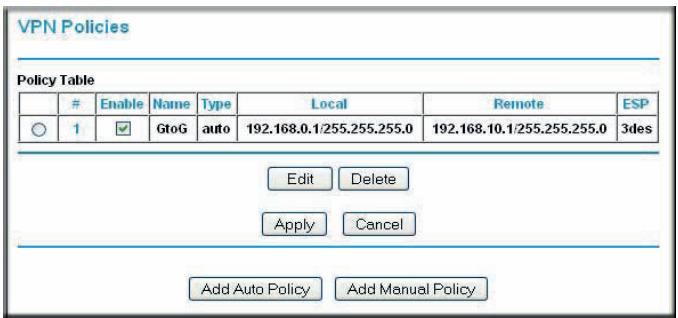
-
Repeat these steps for the N300 Wireless Dual Band ADSL2+ Modem Router DGND3300v2 on LAN B. Pay special attention to the following network settings:
-
General, Remote Address Data (for example, 14.15.16.17)
Remote LAN, Start IP Address -
IP Address (for example, 192.168.0.1)
- Subnet Mask (for example, 255.255.255.0)
-
Pre-shared Key (for example, 12345678)
-
Use the VPN Status screen to activate the VPN tunnel:
Note: The VPN Status screen is only one of three ways to active a VPN tunnel. See Activating a VPN Tunnel on page 94 for information about the other ways.
a. From the main menu, select VPN Status to display the VPN Status/Log screen. Then click VPN Status to display the Current VPN Tunnels (SAs) screen:
b. Click Connect for the VPN tunnel that you want to activate. Review the VPN Status/Log screen (Figure a on page 94) to verify that the tunnel is connected.
Using Manual Policy to Configure VPN Tunnels
As an alternative to IKE, you can use manual keying, in which you must specify each phase of the connection. A manual VPN policy requires all settings for the VPN tunnel to be manually input at each end (both VPN endpoints).
On the main menu, select VPN Policies, and then click the Add Manual Policy radio button to display the VPN - Manual Policy screen:
The following table explains the fields in the VPN - Manual Policy screen.
Table 7. VPN Manual Policy Fields and Settings
| Fields and Settings | Description | |
| General The N300 Wireless Dual Band ADSL2+ Modem Router DGND3300v2 VPN tunnel network connection fields. | Policy Name | Enter a unique name to identify this policy. This name is not supplied to the remote VPN endpoint. It is used only to help you manage the policies. |
| Remote VPN Endpoint | · The remote VPN endpoint must have this VPN's gateway address entered as its remote VPN endpoint. · If the remote endpoint has a dynamic IP address, select Dynamic IP Address. No address data input is required. You can set up multiple remote dynamic IP policies, but only one such policy can be enabled at a time. Otherwise, select an option (IP address or domain name) and enter the address of the remote VPN endpoint to which you want to connect. | |
| Local LAN IP AddressThe remote VPN endpoint must have these IP addresses entered as its remote addresses. | Subnet Mask | Enter the network mask. |
| Single PC - no Subnet | Select this option if there is no LAN (only a single PC) at the remote endpoint. If this option is selected, no additional data is required. | |
| Single/Start IP Address | The IP address for a single address, or the starting address for an address range used on the LAN. If you want to make a single server on your LAN available to remote users, use a single address settings. ·Any. The remote VPN endpoint can be at any IP address. | |
| Finish IP Address | For an address range, enter the finish IP address. This must be an address range used on your LAN. | |
| Subnet Mask | Enter the network mask. | |
| Remote LAN IP AddressThe remote VPN endpoint must have these IP addresses entered as its local addresses. | IP Address | Single PC - no Subnet. Select this option if there is no LAN (only a single PC) at the remote endpoint. If this option is selected, no additional data is required. The typical application is a PC running the VPN client at the remote end. |
| Single/Start IP Address | Enter an IP address on the remote LAN. You can use this setting to access a server. ·For a range of addresses, enter the starting IP address. This must be an address range used on the remote LAN. ·Any. Any outgoing traffic from specified Local IP computers triggers an attempted VPN connection to the remote VPN endpoint. Be sure you want this option before selecting it. | |
| Finish IP Address | Enter the finish IP address for a range of addresses. This must be an address range used on the remote LAN. | |
| Subnet Mask | Enter the network mask. | |
| ESP ConfigurationESP (Encapsulating Security Payload) provides security for the payload (data) sent through the VPN tunnel. | SPI | Enter the required Security Policy Indexes (SPIs). Each policy must have unique SPIs. These settings must match the remote VPN endpoint. The in setting here must match the out setting on the remote VPN endpoint, and the out setting here must match the in setting on the remote VPN endpoint. |
| Encryption | Select an encryption algorithm, and enter the key in the field provided. For 3DES, the keys should be 24 ASCII characters, and for DES, the keys should be 8 ASCII characters. ·DES. The Data Encryption Standard (DES) processes input data that is 64 bits wide, encrypting these values using a 56-bit key. Faster but less secure than 3DES. ·3DES. (Triple DES) achieves a higher level of security by encrypting the data three times using DES with three different, unrelated keys. | |
| Authentication | ||
This chapter describes advanced features of the N300 Wireless Dual Band ADSL2+ Modem Router DGND3300v2. This chapter includes the following sections:
Using the LAN Setup Options on page 112
Using a Dynamic DNS Service on page 116
- Configuring the WAN Setup Options on page 117
Setting Up Quality of Service (QoS) on page 119
- Configuring Static Routes on page 123
- Wireless Repeating (Also Called WDS) on page 125
Using the LAN Setup Options
The LAN Setup screen allows configuration of LAN IP services such as Dynamic Host Configuration Protocol (DHCP) and Routing Information Protocol (RIP).
The N300 wireless modem router is shipped preconfigured to use private IP addresses on the LAN side and to act as a DHCP server. The N300 wireless modem router's default LAN IP configuration is:
LAN IP address. 192.168.0.1
- Subnet mask. 255.255.255.0
These addresses are part of the designated private address range for use in private networks and should be suitable for most applications. If your network has a requirement to use a different IP addressing scheme, you can make those changes in the LAN Setup screen.
To configure LAN settings, log in to the N300 wireless modem router, and from the main menu, select Advanced > LAN Setup. The following screen displays:
Figure 55.
If you make changes, you must click Apply for the changes to take effect.
Note: If you change the LAN IP address of the N300 wireless modem router while connected through the browser, you will be disconnected. You must then open a new connection to the new IP address and log in again.
The LAN Setup fields are explained in the following table.
| Settings | Description | |
| Device Name | A descriptive name for the N300 wireless modem router, which will be shown in the Network on Windows Vista and the Network Explorer on all Windows systems. The Device Name field cannot be blank. | |
| Settings | Description | |
| LAN TCP/IP Setup | IP Address | The LAN IP address of the N300 wireless modem router. |
| IP Subnet Mask | The LAN subnet mask of the N300 wireless modem router. Combined with the IP address, the IP subnet mask allows a device to know which other addresses are local to it, and which must be reached through a gateway or N300 wireless modem router. | |
| RIP Direction | RIP (Router Information Protocol) allows the N300 wireless modem router to exchange routing information with other routers. This setting controls how the N300 wireless modem router sends and receives RIP packets. Both is the default. • Both or Out Only. The N300 wireless modem router broadcasts its routing table periodically. • Both or In Only. The N300 wireless modem router incorporates the RIP information that it receives. • None. The N300 wireless modem router will not send any RIP packets and will ignore any RIP packets received. | |
| RIP Version | This controls the format and the broadcasting method of the RIP packets that the N300 wireless modem router sends. It recognizes both formats when receiving. By default, this is RIP-1. • RIP-1 is universally supported. It is adequate for most networks, unless you have an unusual network setup. • RIP-2 carries more information. Both RIP-2B and RIP-2M send the routing data in RIP-2 format. RIP-2B uses subnet broadcasting. RIP-2M uses multicasting. | |
| DHCP Server | Use Router as a DHCP Server | This check box is usually selected so that the N300 wireless modem router functions as a Dynamic Host Configuration Protocol (DHCP) server. See Using the N300 Wireless Modem Router as a DHCP Server on page 114. |
| Starting IP Address | Specify the start of the range for the pool of IP addresses in the same subnet as the N300 wireless modem router. | |
| Ending IP Address | Specify the end of the range for the pool of IP addresses in the same subnet as the N300 wireless modem router. | |
| Address Reservation For more information, see Address Reservation on page 115. | When you specify a reserved IP address for a computer on the LAN, that computer receives the same IP address each time it accesses the N300 wireless modem router's DHCP server. Assign reserved IP addresses to servers that require permanent IP settings. | |
Using the N300 Wireless Modem Router as a DHCP Server
By default, the N300 wireless modem router functions as a DHCP server, allowing it to assign IP, DNS server, and default gateway addresses to all computers connected to the N300 wireless modem router's LAN. The assigned default gateway address is the LAN address of the N300 wireless modem router. The N300 wireless modem router assigns IP addresses to
the attached computers from a pool of addresses specified in this screen. Each pool address is tested before it is assigned to avoid duplicate addresses on the LAN.
For most applications, the default DHCP and TCP/IP settings of the N300 wireless modem router are satisfactory. Click the link to the online document TCP/IP Networking Basics on page 172 for an explanation of DHCP and information about how to assign IP addresses for your network.
Specify the pool of IP addresses to be assigned by setting the starting IP address and ending IP address. These addresses should be part of the same IP address subnet as the N300 wireless modem router's LAN IP address. Using the default addressing scheme, you should define a range between 192.168.0.2 and 192.168.0.254, although you might wish to save part of the range for devices with fixed addresses.
The N300 wireless modem router delivers the following parameters to any LAN device that requests DHCP:
An IP Address from the range you have defined
- Subnet Mask
- Gateway IP Address (the N300 wireless modem router's LAN IP address)
- Primary DNS Server (if you entered a primary DNS address in the Basic Settings screen; otherwise, the N300 wireless modem router's LAN IP address)
- Secondary DNS Server (if you entered a secondary DNS address in the Basic Settings screen)
To use another device on your network as the DHCP server, or to manually configure the network settings of all of your computers, clear the Use Router as DHCP Server check box. Otherwise, leave it selected. If this service is not selected and no other DHCP server is available on your network, you will need to set your computers' IP addresses manually or they will not be able to access the N300 wireless modem router.
Address Reservation
When you specify a reserved IP address for a computer on the LAN, that computer always receives the same IP address each time it accesses the N300 wireless modem router's DHCP server. Reserved IP addresses should be assigned to computers or servers that require permanent IP settings.
To reserve an IP address:
- Click Add.
- In the IP Address field, type the IP address to assign to the computer or server. (Choose an IP address from the N300 wireless modem router's LAN subnet, such as 192.168.0.x.)
- Type the MAC address of the computer or server.
Tip: If the computer is already present on your network, you can copy its MAC address from the Attached Devices screen and paste it here.
- Click Apply to enter the reserved address into the table.
Note: The reserved address is not assigned until the next time the computer contacts the N300 wireless modem router's DHCP server. Reboot the computer or access its IP configuration and force a DHCP release and renew.
To edit or delete a reserved address entry:
- Select the radio button next to the reserved address you want to edit or delete.
- Click Edit or Delete.
Using a Dynamic DNS Service
If your Internet Service Provider (ISP) gave you a permanently assigned IP address, you can register a domain name and have that name linked with your IP address by public Domain Name Servers (DNS). However, if your Internet account uses a dynamically assigned IP address, you do not know in advance what your IP address will be, and the address can change frequently. In this case, you can use a commercial Dynamic DNS service, which allows you to register your domain to its IP address, and forwards traffic directed at your domain to your frequently changing IP address.
Note: If your ISP assigns a private WAN IP address (such as 192.168.x.x or 10.x.x.x), the Dynamic DNS service will not work because private addresses are not routed on the Internet.
Your N300 wireless modem router contains a client that can connect to the Dynamic DNS service provided by DynDNS.org. You must first visit their website at www.dyndns.org and obtain an account and host name, which you configure in the N300 wireless modem router. Then, whenever your ISP-assigned IP address changes, your N300 wireless modem router automatically contacts the Dynamic DNS service provider, logs in to your account, and registers your new IP address. If your host name is hostname, for example, you can reach your N300 wireless modem router at hostname.dyndns.org.
To configure Dynamic DNS:
- From the main menu, select Advanced > Dynamic DNS to display the Dynamic DNS screen.
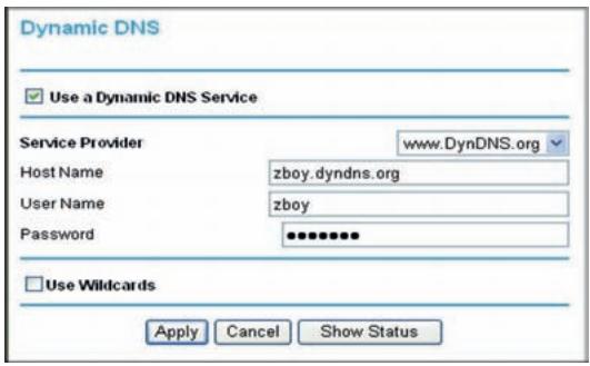
Figure 56.
- Register for an account with one of the Dynamic DNS service providers whose names appear in the Service Provider list. For example, for DynDNS.org, select www.dyndns.org.
- Select the Use a Dynamic DNS Service check box.
- Select the name of your Dynamic DNS service provider.
- Type the host name (or domain name) that your Dynamic DNS service provider gave you.
- Type the user name for your Dynamic DNS account. This is the name that you use to log in to your account, not your host name.
- Type the password (or key) for your Dynamic DNS account.
- If your Dynamic DNS provider allows the use of wildcards in resolving your URL, you can select the Use Wildcards check box to activate this feature. For example, the wildcard feature causes *.yourhost.dyndns.org to be aliased to the same IP address as yourhost.dyndns.org.
- Click Apply to save your configuration.
Configuring the WAN Setup Options
The WAN Setup screen lets you configure a DMZ (demilitarized zone) server, change the Maximum Transmit Unit (MTU) size, and enable the N300 wireless modem router to respond to a ping on the WAN (Internet) port. From the main menu, under Advanced, click WAN Setup to view the WAN Setup screen.
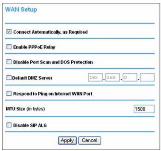
Figure 57.
The WAN Setup fields are described in the following table:
| Setting | Description |
| Connect Automatically, as Required | Usually, this check box is selected, so that an Internet connection is made automatically whenever Internet-bound traffic is detected. If this causes high connection costs, you can clear the check box to disable this feature. If this setting is disabled, you must connect manually, using the screen that you access by clicking the Connection Status button on the Status screen. If you have an Always on connection, this setting has no effect. |
| Enable PPPoE Relay | Selecting this check box allows a PPPoE client on a local PC to connect to a remote PPPoE server with the N300 wireless modem router acting as a relay agent. |
| Disable Port Scan and DOS Protection | The firewall protects your LAN against port scans and denial of service (DOS) attacks. This protection should be disabled only in special circumstances. |
| Default DMZ Server | This feature is sometimes helpful when you are using some online games and videoconferencing. Be careful when using this feature because it makes the firewall security less effective. See Configuring Static Routes on page 123. |
| Respond to Ping on Internet WAN Port | If you want the N300 wireless modem router to respond to a ping from the Internet, select this check box. This should be used only as a diagnostic tool, since it allows your N300 wireless modem router to be discovered. Do not select this check box unless you have a specific reason to do so. |
| MTU Size (in bytes) | The normal MTU (Maximum Transmit Unit) value for most Ethernet networks is 1500 bytes, or 1492 bytes for PPPoE connections. For some ISPs you might need to reduce the MTU. This is rarely required, and should not be done unless you are sure it is necessary for your ISP connection. See Changing the MTU Size on page 134. |
| Disable SIP ALG | The Session Initiation Protocol (SIP) Application Level Gateway (ALG) is enabled by default to optimize VoIP phone calls that use the SIP. The Disable SIP ALG check box allows you to disable the SIP ALG. Disabling the SIP ALG might be useful when running certain applications. |
Setting Up a Default DMZ Server
The default DMZ server feature is helpful when using some online games and videoconferencing applications that are incompatible with Network Address Translation (NAT). The N300 wireless modem router is programmed to recognize some of these applications and to work correctly with them, but there are other applications that might not function well. In some cases, one local computer can run the application correctly if that computer's IP address is entered as the default DMZ server.

WARNING!
DMZ servers pose a security risk. A computer designated as the default DMZ server loses much of the protection of the firewall and is exposed to exploits from the Internet. If compromised, the DMZ server computer can be used to attack other computers on your network.
Incoming traffic from the Internet is usually discarded by the N300 wireless modem router unless the traffic is a response to one of your local computers or a service that you have configured in the Port Forwarding screen. Instead of discarding this traffic, you can have it forwarded to one computer on your network. This computer is called the default DMZ server.
The WAN Setup screen lets you configure a default DMZ server.
To assign a computer or server to be a default DMZ server:
- In the last Default DMZ Server field, type the last digit of the IP address for that computer. To remove the default DMZ server, enter 0 (zero).
- Select the Default DMZ Server check box, and click Apply.
Setting Up Quality of Service (QoS)
Quality of Service (QoS) is an advanced feature that can be used to prioritize some types of traffic ahead of others. The N300 wireless modem router can provide QoS prioritization over the wireless link and on the Internet connection.
The N300 wireless modem router supports Wi-Fi Multimedia Quality of Service (WMM QoS) to prioritize wireless voice and video traffic over the wireless link. WMM QoS provides prioritization of wireless data packets from different applications based on four access categories: voice, video, best effort, and background. For an application to receive the benefits of WMM QoS, both it and the client running that application must be WMM enabled. Legacy applications that do not support WMM, and applications that do not require QoS, are assigned to the best effort category, which receives a lower priority than voice and video.
Configuring QoS for Internet Access
To specify prioritization of traffic, you must add or create a policy for the type of traffic. To display the QoS Setup screen, from the main menu, select Advanced > QoS Setup.
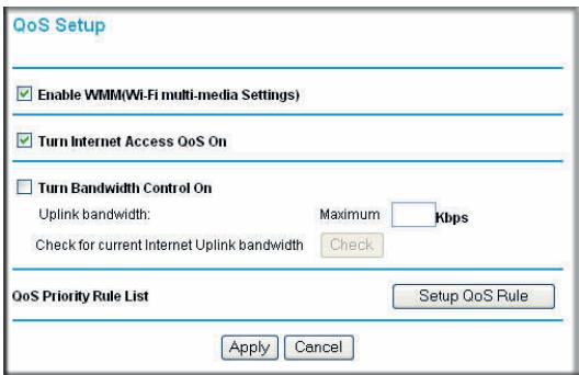
Figure 58.
WMM QoS is enabled by default. You can disable it by selecting QoS Setup from the main menu, clearing the Enable WMM (Wi-Fi multi-media Settings) check box, and clicking Apply.
You can give prioritized Internet access to the following types of traffic:
- For specific applications or online games, see QoS for Applications and Online Gaming on page 120.
- For QoS on individual Ethernet LAN ports of the N300 wireless modem router, see QoS for a Router LAN Port on page 122.
- For QoS from a specific device by MAC address, see QoS for a MAC Address on page 122.
QoS for Applications and Online Gaming
To create a QoS policy for traffic for specific applications or online games:
- From the main menu, select Advanced > QoS Setup. The QoS Setup screen displays.
- Click Setup QoS rule. The QoS Priority Rule List screen displays.
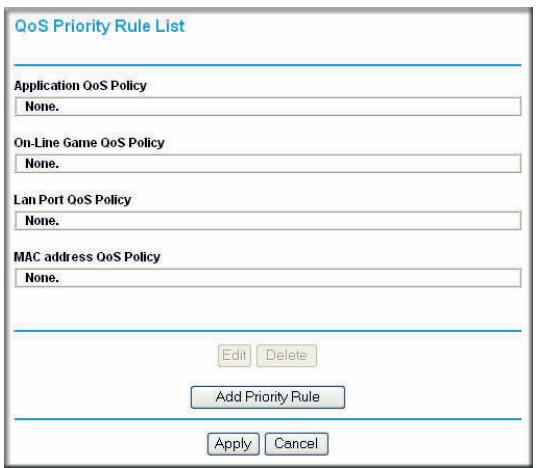
Figure 59.
- Click Add Priority Rule. The QoS - Priority Rules screen displays.
- In the Priority Category list, either use the default selection of Applications, or select Online Gaming. A drop-down list of predefined applications or games is available.
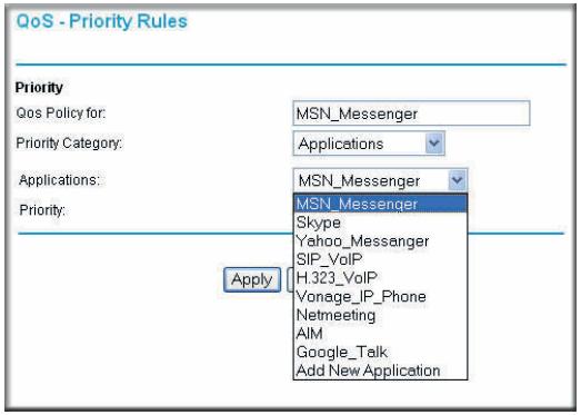
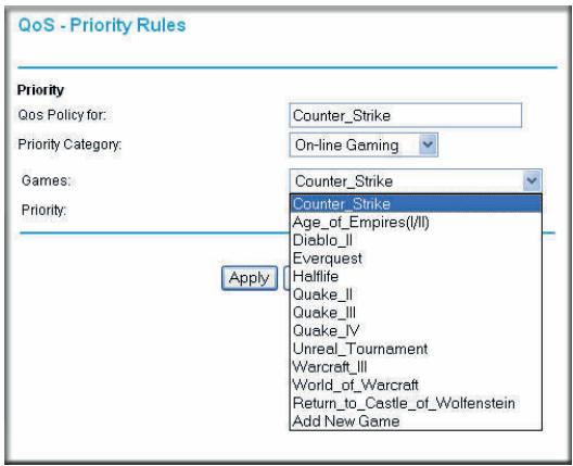
Figure 60.
- You can select an existing item, or you can scroll to the bottom of the list and select Add a New Application or Add a New Game.
a. If you choose to add a new entry, the screen expands as shown:
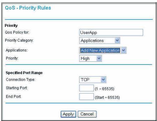
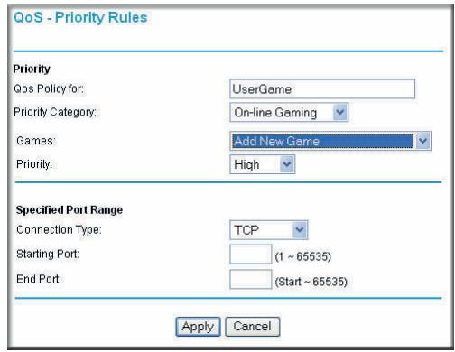
Figure 61.
b. In the QoS Policy for field, enter a descriptive name for the new application or game.
c. Select the connection type, either TCP, UDP, or both (TCP/UDP), and specify the port number or range of port numbers used by the application or game.
- From the Priority drop-down list, select the priority that this traffic should receive relative to other applications and traffic when accessing the Internet. The options are Low, Normal, High, and Highest.
- Click Apply to save this rule to the QoS Policy list and return to the QoS Setup screen.
- In the QoS Setup screen, select the Turn Internet Access QoS On check box.
- Click Apply.
QoS for a Router LAN Port
To create a QoS policy for a device connected to one of the router's LAN ports:
- From the main menu, select Advanced > QoS Setup. The QoS Setup screen displays.
- Click Setup QoS Rule.
- In the Priority Category field, select Ethernet LAN Port. The screen changes:
Figure 62.
- In the LAN Ports list, select the LAN port that will have a QoS policy.
- From the Priority drop-down list, select the priority that this port's traffic should receive relative to other applications and traffic when accessing the Internet. The options are Low, Normal, High, and Highest.
- Click Apply to save this rule to the QoS Policy list and return to the QoS Setup screen.
- In the QoS Setup screen, select the Turn Internet Access QoS On check box.
- Click Apply.
QoS for a MAC Address
To create a QoS policy for traffic from a specific MAC address:
- From the main menu, select Advanced > QoS Setup. The QoS Setup screen displays.
- Click Add Priority Rule.
- In the Priority Category field, select MAC Address. The screen changes:
Figure 63.
- If the device to be prioritized appears in the MAC Device List, select it. The information from the MAC Device List is used to populate the policy name, MAC Address, and Device Name fields. If the device does not appear in the MAC Device List, click Refresh. If it still does not appear, you must complete these fields manually.
- From the Priority drop-down list, select the priority that this device's traffic should receive relative to other applications and traffic when accessing the Internet. The options are Low, Normal, High, and Highest.
- Click Apply to save this rule to the QoS Policy list and return to the QoS Setup screen.
- In the QoS Setup screen, select the Turn Internet Access QoS On check box.
- Click Apply.
Editing or Deleting an Existing QoS Policy
To edit or delete an existing QoS policy:
- From the main menu, select Advanced > QoS Setup. The QoS Setup screen displays.
-
Select the radio button for the QoS policy to be edited or deleted, and do one of the following:
-
Click Delete to remove the QoS policy.
-
Click Edit to edit the QoS policy. Follow the instructions in the preceding sections to change the policy settings.
-
Click Apply in the QoS Setup screen to save your changes.
Configuring Static Routes
Static routes provide additional routing information to your N300 wireless modem router. Under usual circumstances, the N300 wireless modem router has adequate routing information after it has been configured for Internet access, and you do not need to configure additional static routes. You must configure static routes only for unusual cases such as multiple routers or multiple IP subnets located on your network.
As an example of when a static route is needed, consider the following case:
- Your primary Internet access is through a cable modem to an ISP.
- You have an ISDN router on your home network for connecting to the company where you are employed. This router's address on your LAN is 192.168.0.100.
- Your company's network address is 134.177.0.0.
When you first configured your N300 wireless modem router, two implicit static routes were created. A default route was created with your ISP as the gateway, and a second static route was created to your local network for all 192.168.0.x addresses. With this configuration, if you attempt to access a device on the 134.177.0.0 network, your N300 wireless modem router forwards your request to the ISP. The ISP forwards your request to the company where you are employed, and the request is likely to be denied by the company's firewall.
In this case you must define a static route, telling your N300 wireless modem router that 134.177.0.0 should be accessed through the ISDN router at 192.168.0.100.
In this example:
- The Destination IP Address and IP Subnet Mask fields specify that this static route applies to all 134.177.x.x addresses.
- The Gateway IP Address field specifies that all traffic for these addresses should be forwarded to the ISDN router at 192.168.0.100.
A Metric value of 1 will work since the ISDN router is on the LAN. - Private is selected only as a precautionary security measure in case RIP is activated.
From the main menu, select Advanced > Static Routes. The Static Routes screen displays.
Figure 64.
To add or edit a static route:
- Click Add to open the Static Routes screen.
Figure 65.
- In the Route Name field, type a name for this static route. (This is for identification purposes only.)
- Select the Private check box if you want to limit access to the LAN only. If Private is selected, the static route is not reported in RIP.
- Select the Active check box to make this route effective.
- Type the destination IP address of the final destination.
- Type the IP subnet mask for this destination. If the destination is a single host, type 255.255.255.255.
- Type the gateway IP address, which must be a router on the same LAN segment as the N300 wireless modem router.
- Type a number between 1 and 15 as the metric value. This represents the number of routers between your network and the destination. Usually, a setting of 2 or 3 works, but if this is a direct connection, set it to 1.
- Click Apply to have the static route entered into the table.
Wireless Repeating (Also Called WDS)
The N300 Wireless Modem Router can be used with a wireless access point (AP) to build large bridged wireless networks. Wireless repeating is a type of Wireless Distribution System (WDS).

WARNING!
If you use the wireless repeating function, your options for wireless security are limited to None or WEP. For more information about wireless security, see Chapter 2, Wireless Settings.
The following figure shows a wireless repeating scenario:
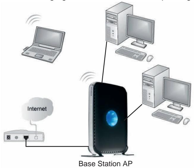
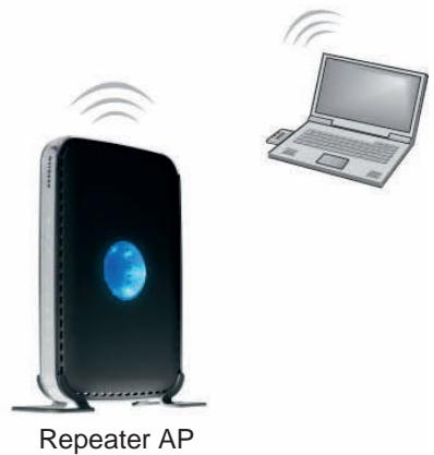
Figure 66.
To set up a wireless network using WDS, the following conditions must be met for both APs:
- Both APs must use the same SSID, wireless channel, and encryption mode (see Manually Configuring Your Wireless Settings on page 18 or Using Push 'N' Connect (WPS) to Configure Your Wireless Network on page 24).
- Both APs must be on the same LAN IP subnet. That is, all the AP LAN IP addresses are in the same network.
- All LAN devices (wired and wireless computers) must be configured to operate in the same LAN network address range as the APs.
- When the N300 wireless modem router is in dual band mode (the Mode field on the Wireless Settings screen is set to Up to 300 Mbps at 5 GHz and 54 Mbps at 2.4 GHz), the WDS function works only in 5 GHz 11N mode. To use the 2.4 GHz 11g protocol with WDS, set the Mode field in the Wireless Settings screen to Up to 300 Mbps at 2.4 GHz. If you make changes in the Wireless Settings screen, click Apply so that they take effect.
Wireless Repeating Function
You can view or change wireless repeater settings for the N300 wireless modem router. From the main menu of the browser interface, under Advanced, click Wireless Repeating Function to display the Wireless Repeating Function screen.
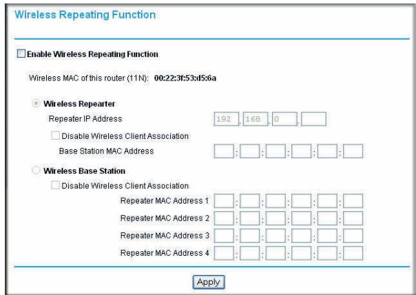
Figure 67.
The N300 wireless modem router supports two modes of the wireless repeating function, and allows you to control wireless client association:
- Wireless Repeater. The N300 wireless modem router sends all traffic from its local wireless or wired computers to a remote AP. To configure this mode, you must know the MAC address of the remote parent AP.
- Wireless Base Station. The N300 wireless modem router acts as the parent AP, bridging traffic to and from the child repeater AP, as well as handling wireless and wired local computers. To configure this mode, you must know the MAC addresses of the child repeater AP.
- Disable Wireless Client Association. Usually this check box is cleared so that the N300 wireless modem router is an access point for wireless computers.
If this check box is selected, the N300 wireless modem router communicates wirelessly only with other APs whose MAC addresses are listed in this screen. The N300 wireless modem router still communicates with wire-connected LAN devices.
Setting Up the Base Station
The wireless repeating function works only in hub and spoke mode. The units cannot be daisy chained. You must know the wireless settings for both units. You must know the MAC address of the remote unit. First, set up the base station, and then set up the repeater.
To set up the base station:
- Set up both units with exactly the same wireless settings (SSID, mode, channel, and security). Note that the wireless security option must be set to None or WEP.
- Log in to the N300 wireless modem router base unit. Select Advanced > Wireless Repeating Function to display the Wireless Repeating Function screen.
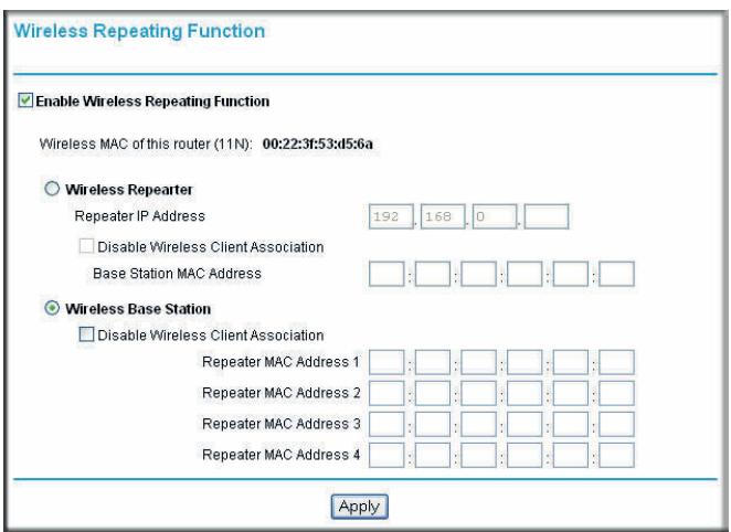
Figure 68.
- Select the Enable Wireless Repeating Function check box and the Wireless Base Station radio button.
- Enter the MAC address for the repeater units.
- Click Apply to save your changes.
Setting Up a Repeater Unit
Use a wired Ethernet connection to set up the repeater unit to avoid conflicts with the wireless connection to the base station.
Note: If you are using the N300 Wireless Dual Band ADSL2+ Modem Router DGND3300v2 base station with a non-NETGEAR N300 wireless modem router as the repeater, you might need to change additional configuration settings. In particular, you should disable the DHCP server function on the wireless repeater AP.
To configure a N300 wireless modem router as a repeater unit:
- If you are using the same model of N300 wireless modem router for both the base station and repeaters, you must change the LAN IP address for each repeater to a different IP address in the same subnet (see Using the LAN Setup Options on page 112).
Note: Failing to change the LAN IP address will cause an IP address conflict in the network because the factory default LAN IP is the same for both units.
- Log in to the router that will be the repeater. Check the Wireless Settings screen, and verify that the wireless settings match the base unit exactly. The wireless security option must be set to WEP or None.
- In the Wireless Repeating Function screen, select the Enable Wireless Repeater Mode radio button.
This IP address must be in the same subnet as the base station but different from the LAN IP of the base station.
- Fill in the Base Station MAC Address field.
- Click Apply to save your changes.
- Verify connectivity across the LANs.
A computer on any wireless or wired LAN segment of the N300 wireless modem router should be able to connect to the Internet or share files and printers with any other wireless or wired computer or server connected to the other AP.
This chapter describes features to help you manage your N300 Wireless Dual Band ADSL2+ Modem Router DGND3300v2.
This chapter includes the following sections:
Common Connection Types on page 130
Assessing Your Speed Requirements on page 131
- Optimizing Your Network Bandwidth on page 132
- Optimizing Wireless Performance on page 133
Changing the MTU Size on page 134
Universal Plug and Play on page 135
Common Connection Types
Common connection types and their speed and security considerations are:
- Broadband Internet. Your Internet connection speed is determined by your modem type, (ADSL), as well as the connection speed of the sites to which you connect, and general Internet traffic. ADSL modem connections are asymmetrical, meaning they have a lower data rate to the Internet (upstream) than from the Internet (downstream). Keep in mind that when you connect to another site that also has an asymmetrical connection, the data rate between your sites is limited by each side's upstream data rate. A typical residential ADSL connection provides a downstream throughput of about 1 to 3 megabits per second (Mbps). Newer technologies such as ADSL2+ and Fiber to the Home (FTTH) will increase the connection speed to tens of Mbps.
- Wireless. Your N300 wireless modem router provides a wireless data throughput of up to 300 Mbps using technology called multiple input, multiple output (MIMO), in which multiple antennas transmit multiple streams of data. The use of multiple antennas also provides excellent range and coverage. With the introduction of the newer WPA and WPA2 encryption and authentication protocols, wireless security is extremely strong.
To get the best performance, use RangeMax NEXT adapters for your computers. Although your N300 wireless modem router is compatible with older 802.11b and 802.11g adapters, the use of these older wireless technologies in your network can result in lower throughput overall (typically less than 10 Mbps for 802.11b and less than 40 Mbps for
802.11g). In addition, many older wireless products do not support the latest security protocols, WPA and WPA2.
- Powerline. For connecting rooms or floors that are blocked by obstructions or are distant vertically, consider networking over your building's AC wiring. NETGEAR's Powerline HD family of products delivers up to 200 Mbps to any outlet, while the older-generation XE family of products delivers 14 Mbps or 85 Mbps. Data transmissions are encrypted for security, and you can configure an individual network password to prevent neighbors from connecting.
- The Powerline HD family of products can coexist on the same network with older-generation XE family products or HomePlug 1.0 products, but they are not interoperable with these older products.
- Wired Ethernet. As gigabit-speed Ethernet ports (10/100/1000 Mbps) become common on newer computers, wired Ethernet remains a good choice for speed, economy, and security. Gigabit Ethernet can extend up to 100 meters with twisted-pair wiring of CAT-5e or better. A wired connection is not susceptible to interference, and eavesdropping would require a physical connection to your network.
Note: Actual data throughput will vary. Network conditions and environmental factors, including volume of network traffic, building materials and construction, and network overhead, can lower actual data throughput rate.
Assessing Your Speed Requirements
Because your Internet connection is likely to operate at a much lower speed than your local network, faster local networking technologies might not improve your Internet experience. However, many emerging home applications require high data rates. For example:
- Streaming HD video requires 10 to 30 Mbps per stream. Because latency and packet loss can disrupt your video, plan to provide at least twice the capacity you need.
- Streaming MP3 audio requires less than 1 Mbps per stream and does not strain most modern networks. Like video, however, streaming audio is also sensitive to latency and packet loss, so a congested network or a noisy link can cause problems.
- Backing up computers over the network has become popular due to the availability of inexpensive mass storage. The following table shows the time to transfer 1 gigabyte (GB) of data using various networking technologies.
| Network Connection | Theoretical Raw Transfer Time |
| Gigabit wired Ethernet | 8 seconds |
| RangeMax NEXT Wireless-N | 26 seconds |
| Powerline HD | 40 seconds |
| 100 Mbps wired Ethernet | 80 seconds |
| 802.11n wireless | 45 seconds |
| 802.11g wireless | 150 seconds |
| 802.11b wireless | 700 seconds |
| 10 Mbps wired Ethernet | 800 seconds |
| Cable modem (3 Mbps) | 2700 seconds |
| Analog modem (56 kbps) | 144,000 seconds (40 hours) |
Optimizing Your Network Bandwidth
As your network grows, it might consist of several segments of different networking technologies, each providing different throughput. In planning your network, you should first consider which devices will have the heaviest traffic flow between them. Examples are:
- A media center in one room streaming high-definition video from a server in another room
- A storage device that is used for backing up your computers
Next, consider the throughput of your network devices. Where possible, make the heaviest-traffic connections using higher-speed technologies, with no lower-speed bottlenecks in the path.
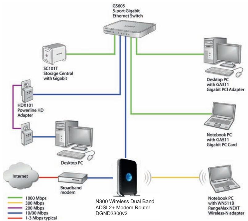
Figure 69.
The previous figure shows a sample network using multiple networking technologies. In this network, the two PCs with Gigabit (1000 Mbps) Ethernet adapters have a gigabit connection through the GS605 switch to the storage server. This connection should allow for extremely fast backups or quick access to large files on the server. The PC connected through a pair of Powerline HD adapters is limited to the 200 Mbps speed of the Powerline HD connection. Although any of the links in this example would be sufficient for high-traffic applications such as streaming HD video, the use of older devices such as 10 Mbps Ethernet or 802.11b wireless would create a significant bottleneck.
Optimizing Wireless Performance
The speed and operating distance or range of your wireless connection can vary significantly based on the physical placement of the wireless router. You should choose a location for your router that will maximize the network speed.
Note: Failure to follow these guidelines can result in significant performance degradation or inability to wirelessly connect to the router. For complete range and performance specifications, click the link to the online document Wireless Networking Basics in Appendix E.
The following list describes how to optimize wireless router performance.
- Identify critical wireless links.
If your network has several wireless devices, decide which wireless devices need the highest data rate, and locate the router near them. Many wireless products have automatic data-rate fallback, which allows increased distances without loss of connectivity. This also means that devices that are farther away might be slower. Therefore, the most critical links in your network are those where the traffic is high and the distances are great. Optimize those first.
- Choose placement carefully.
For best results, place your router:
- Near the center of the area in which your computers will operate.
- In an elevated location such as a high shelf where the wirelessly connected computers have line-of-sight access (even if through walls).
- Avoid obstacles to wireless signals.
- Keep wireless devices at least 2 feet from large metal fixtures such as file cabinets, refrigerators, pipes, metal ceilings, reinforced concrete, and metal partitions.
-
Keep away from large amounts of water such as fish tanks and water coolers.
-
Reduce interference.
-
Avoid windows unless communicating between buildings.
-
Place wireless devices away from various electromagnetic noise sources, especially those in the 2400–2500 MHz frequency band. Common noise-creating sources are:
Computers and fax machines (no closer than 1 foot)
- Copying machines, elevators, and cell phones (no closer than 6 feet)
- Microwave ovens (no closer than 10 feet)
-
Choose your settings.
-
Use a scanning utility to determine what other wireless networks are operating nearby, and choose an unused channel.
- Turn off SSID broadcast, and change the default SSID. Other nearby devices might automatically try to connect to your network several times a second, which can cause significant performance reduction.
Use WMM to improve the performance of voice and video traffic over the wireless link.
Changing the MTU Size
The Maximum Transmission Unit (MTU) is the largest data packet a network device transmits. When one network device communicates across the Internet with another, the data packets travel through many devices along the way. If any device in the data path has a lower MTU setting than the other devices, the data packets must be split or "fragmented" to accommodate the one with the smallest MTU.
The best MTU setting for NETGEAR equipment is often just the default value, and changing the value might fix one problem but cause another. Leave MTU unchanged unless one of these situations occurs:
-
You have problems connecting to your ISP or other Internet service, and the technical support of either the ISP or NETGEAR recommends changing the MTU setting. These might require an MTU change:
-
A secure website that won't open, or displays only part of a Web page
Yahoo e-mail - MSN
-
America Online's DSL service
-
You use VPN and have severe performance problems.
- You used a program to optimize MTU for performance reasons, and now you have connectivity or performance problems.
Note: An incorrect MTU setting can cause Internet communication problems such as the inability to access certain Web sites, frames within websites, secure login pages, or FTP or POP servers.
If you suspect an MTU problem, a common solution is to change the MTU to 1400. If you are willing to experiment, you can gradually reduce the MTU from the maximum value of 1500 until the problem goes away. The following table describes common MTU sizes and applications.
| MTU | Application |
| 1500 | The largest Ethernet packet size and the default value. This is the typical setting for non-PPPoE, non-VPN connections, and is the default value for NETGEAR routers, adapters, and switches. |
| 1492 | Used in PPPoE environments. |
| 1472 | Maximum size to use for pinging. (Larger packets are fragmented.) |
| 1468 | Used in some DHCP environments. |
| 1460 | Usable by AOL if you do not have large e-mail attachments, for example. |
| 1436 | Used in PPTP environments or with VPN. |
| 1400 | Maximum size for AOL DSL. |
| 576 | Typical value to connect to dial-up ISPs. |
To change the MTU size:
- In the main menu, select Advanced > WAN Setup.
- In the MTU Size field, enter a new size between 64 and 1500.
- Click Apply to save the new configuration.
Universal Plug and Play
Universal Plug and Play (UPnP) helps devices, such as Internet appliances and computers, to access the network and connect to other devices as needed. UPnP devices can automatically discover the services from other registered UPnP devices on the network.
Note: If you use applications such as multiplayer gaming, peer-to-peer connections, real-time communications such as instant messaging, or remote assistance (a feature in Windows XP), you should enable UPnP.
To turn on Universal Plug and Play:
- From the main menu, click Advanced > UPnP. The UPnP screen displays.
Figure 70.
-
The available settings and information in this screen are:
-
Turn UPnP On. UPnP can be enabled or disabled for automatic device configuration. The default setting for UPnP is disabled. If this check box is not selected, the router does not allow any device to automatically control the resources, such as port forwarding (mapping) of the router.
- Advertisement Period. The advertisement period is how often the router broadcasts its UPnP information. This value can range from 1 to 1440 minutes. The default period is 30 minutes. Shorter durations ensure that control points have current device status at the expense of additional network traffic. Longer durations might compromise the freshness of the device status but can significantly reduce network traffic.
- Advertisement Time To Live. The time to live for the advertisement is measured in hops (steps) for each UPnP packet sent. The time to live hop count is the number of steps a broadcast packet is allowed to propagate for each UPnP advertisement before it disappears. The number of hops can range from 1 to 255. The default value for the advertisement time to live is 4 hops, which should be fine for most home networks. If you notice that some devices are not being updated or reached correctly, then it might be necessary to increase this value.
-
UPnP Portmap Table. The UPnP Portmap Table displays the IP address of each UPnP device that is currently accessing the router and which ports (Internal and External) that device has opened. The UPnP Portmap Table also displays what type of port is open and whether that port is still active for each IP address.
-
Click Apply to save your settings.
This appendix provides information about troubleshooting your N300 Wireless Dual Band ADSL2+ Modem Router DGND3300v2. After each problem description, instructions are provided to help you diagnose and solve the problem. As a first step, review the Quick Tips.
Tip: NETGEAR provides helpful articles, documentation, and the latest firmware updates at http://www.netgear.com/support.
This chapter includes the following sections:
Quick Tips on page 137
Troubleshooting with the LEDs on page 138
- Cannot Access the N300 Wireless Modem Router Menu on page 140
Cannot Access the Internet on page 141
- Troubleshooting a Network Using the Ping Utility on page 142
Problems with Date and Time on page 144
- Wireless Connectivity on page 145
Viewing Available Networks on page 145
Quick Tips
This section describes tips for troubleshooting some common problems.
| Recommendation | Instructions |
| You can turn off the dome lights for the N300 wireless modem router. | Tap the dome to turn off the lights. These lights identify the activity of the eight internal antennas, flashing to show which combination of antennas is receiving the strongest signals. |
| Be sure to restart your network in this sequence. | 1. Unplug the N300 wireless modem router. 1. Turn off the computers. 2. Plug in the N300 wireless modem router. Wait 1 minute. 3. Turn on the computers. |
| Make sure that the Ethernet cables are securely plugged in. | For each powered-on computer connected to the N300 wireless modem router by an Ethernet cable, the corresponding numbered router LAN port LED is on. |
| Make sure that the wireless settings in the computer and router match exactly. | ·For a wirelessly connected computer, the wireless network name (SSID) and wireless security settings of the N300 wireless modem router and wireless computer must match exactly. ·If you set up an access list in the Advanced Wireless Settings screen, you must add each wireless computer's MAC address to the N300 wireless modem router's access list. |
| Make sure that the network settings of the computer are correct. | ·Wired and wirelessly connected computers must have network (IP) addresses on the same network as the router. The simplest way to ensure this is to configure each computer to obtain an IP address automatically using DHCP. Click the link to the online document Preparing Your Network in Appendix E, or see the documentation that came with your computer. ·Some cable modem service providers require you to use the MAC address of the computer initially registered on the account. You can view the MAC address in the Attached Devices screen. |
| Check the Test LED to verify correct N300 wireless modem router operation. | If the Test LED does not turn off within 2 minutes after you turn the N300 wireless modem router on, reset the router according to the instructions in Using the Restore Factory Settings Button on page 147. |
Troubleshooting with the LEDs
After you turn on power to the N300 wireless modem router, the following sequence of events should occur:
-
When power is first applied, verify that the Power LED is on.
-
After approximately 10 seconds, verify that:
The Power LED is green.
- The LAN port LEDs are lit for any local ports that are connected. If a LAN port is connected to a 100 Mbps device, verify that the port's LED is green. If the port is 10 Mbps, the LED is amber.
- The ADSL link LED is lit, indicating that a link has been established to the connected device.
The Wireless LEDs are lit.
If any of the conditions in step 2 on page 138 does not occur, see the following table.
| Situation | Recommended Action |
| Power LED is off. | If the Power and other LEDs are off when your router is turned on: ·Make sure that the power cord is correctly connected to your router and that the power supply adapter is correctly connected to a functioning power outlet. ·Check that you are using the power adapter supplied by NETGEAR for this product. If the error persists, you have a hardware problem and should contact Technical Support. |
| Power LED is red. The power LED turns red when you depress the Restore Factory Settings button, and blinks red 3 times when that button is released. This is normal and does not indicate a problem. | If the Power LED remains red, there is a fault within the router. ·Cycle the power to see if the router recovers. ·Clear the router's configuration to factory defaults. This sets the router's IP address to 192.168.0.1 or http://www.routerlogin.net. This procedure is explained in Restoring the Factory Configuration Settings on page 147. If the error persists, you might have a hardware problem and should contact Technical Support. |
| LEDs never turn off. | When the router is turned on, the LEDs turn on for about 10 seconds and then turn off. If all the LEDs stay on, there is a fault within the router. If all LEDs are still on 1 minute after power-up: ·Cycle the power to see if the router recovers. ·Clear the router's configuration to factory defaults as explained in Restoring the Factory Configuration Settings on page 147. If the error persists, you might have a hardware problem and should contact Technical Support at www.netgear.com/support. |
| ADSL Link LED is off. | ·Disconnect all telephones on the line. If this solves the problem, reconnect the telephones one at a time, being careful to use a microfilter on each telephone. If the microfilters are connected correctly, you should be able to connect all your telephones. ·Check that the telephone company has made the connection to your line and tested it. ·Verify that you are connected to the correct telephone line. If you have more than one phone line, be sure that you are connected to the line with the ADSL service. It might be necessary to use a swapper if your ADSL signal is on pins 1 and 4 of the RJ-11 jack. The N300 wireless modem router uses pins 2 and 3. |
| Internet LED is red. | The N300 wireless modem router cannot access the Internet. See Cannot Access the Internet on page 141. |
| The Ethernet port LEDs are off. | If the Ethernet port LEDs do not light when the Ethernet connection is made, check the following: • Make sure that the Ethernet cable connections are secure at the N300 wireless modem router and computer. • Make sure that power is turned on to the connected modem or computer. |
| Wireless LEDs are off. | If the Wireless LEDs do not come on, verify that the Enable Wireless Router Radio check box is selected on the Advanced Wireless Settings screen. See Configuring Advanced WPS Settings on page 27. |
Cannot Access the N300 Wireless Modem Router Menu
If you are unable to access the router's menu from a computer on your local network, check the following:
- If you are using an Ethernet-connected computer, check the Ethernet connection between the computer and the N300 wireless modem router.
- Make sure your computer's IP address is on the same subnet as the router. If you are using the recommended addressing scheme, your computer's address should be in the range of 192.168.0.2 to 192.168.0.254. Click the link to Preparing Your Network in Appendix E to find your computer's IP address.
- If your computer's IP address is shown as 169.254.x.x:, it might because recent versions of Windows and MacOS generate and assign an IP address if the computer cannot reach a DHCP server. These auto generated addresses are in the range of 169.254.x.x. If your IP address is in this range, check the connection from the computer to the router and reboot your computer.
- If your router's IP address was changed and you do not know the current IP address, clear the router's configuration to factory defaults. This sets the router's IP address to 192.168.0.1 or http://www+ruterlogin.net. This procedure is explained in Restoring the Factory Configuration Settings on page 147.
- Make sure your browser has Java, JavaScript, or ActiveX enabled. If you are using Internet Explorer, click Refresh to be sure the Java applet is loaded.
Try quitting the browser and launching it again. - Make sure that you are using the correct login information. The login name is admin and the default password is password. Make sure that Caps Lock is off when entering this information.
If the N300 wireless modem router does not save changes you have made in the N300 wireless modem router menu, check the following:
- When entering configuration settings, be sure to click the Apply button before moving to another screen, or your changes are lost.
- Click the Refresh or Reload button in the Web browser. The changes might have occurred, but the Web browser might be caching the old configuration.
Cannot Access the Internet
Note: If you are installing the N300 wireless modem router and have not yet configured the Internet connection, see Chapter 1, Router Internet Setup, or the N300 Wireless Dual Band ADSL2+ Modem Router Installation Guide.
If your Internet connection was working previously, it is possible that this is due to a problem at your Internet Service Provider (ISP). If you can access your router but you are unable to access the Internet, you can check its configuration, and you can determine whether the router can obtain an IP address from your ISP.
Checking the Configuration
To check the router configuration to make sure that it is correct:
- Start your browser, and select an external site such as http://www.netgear.com.
-
Access the main menu of the router at http://www.routerlogin.net.
-
Select Basic Settings to view the Basic Settings screen.
- Select ADSL to view the Multiplexing method, VPI, and VCI settings.
- You can select Setup Wizard and allow the N300 wireless modem router to automatically detect your Internet connection.
Checking the WAN IP Address
Unless your ISP provides a fixed IP address, your router must request an IP address from the ISP. You can determine whether the request was successful using the Router Status screen.
To check the WAN IP address:
- Start your browser, and select an external site such as http://www.netgear.com.
- Access the main menu of the router at http://www_ROUTerlogin.net.
- Under Maintenance, select RouterStatus.
- Check that an IP address is shown for the Internet port. If 0.0.0.0 is shown, your router has not obtained an IP address from your ISP.
If your router cannot obtain an IP address from the ISP, you might need to force your cable or DSL modem to recognize your new router by restarting your network, as described in Quick Tips on page 137.
If your router is still unable to obtain an IP address from the ISP, the problem might be one of the following:
- Your ISP might require a login program.
Ask your ISP whether they require PPP over Ethernet (PPPoE) or some other type of login.
If your ISP requires a login, the login name and password might be set incorrectly.
- Your ISP might check for your computer's host name.
Assign the computer host name of your ISP account as the account name in the Basic Settings screen.
-
Your ISP allows only one Ethernet MAC address to connect to Internet and might check for your computer's MAC address. In this case, do one of the following:
-
Inform your ISP that you have bought a new network device, and ask them to use the router's MAC address.
- Configure your router to spoof your computer's MAC address.
If your router can obtain an IP address, but your computer is unable to load any Web pages from the Internet:
- Your computer might not recognize any DNS server addresses.
A DNS server is a host on the Internet that translates Internet names (such as www addresses) to numeric IP addresses. Typically, your ISP provides the addresses of one or two DNS servers for your use. If you entered a DNS address during the router's configuration, reboot your computer, and verify the DNS address as described in the online document you can access from Preparing Your Network in Appendix E. You can also configure your computer manually with DNS addresses, as explained in your operating system documentation.
- Your computer might not have the router configured as its TCP/IP gateway.
If your computer obtains its information from the router by DHCP, reboot the computer, and verify the gateway address as described in the online document you can access from Preparing Your Network in Appendix E.
- You might be running login software that is no longer needed.
If your ISP provided a program to log you in to the Internet (such as WinPoET), you no longer need to run that software after installing your N300 wireless modem router. You might need to go to Internet Explorer and select Tools > Internet Options, click the Connections tab, and select Never dial a connection.
Troubleshooting a Network Using the Ping Utility
Most network devices and routers contain a ping utility that sends an echo request packet to the designated device. The device then responds with an echo reply. You can easily troubleshoot a network by using the ping utility in your computer or workstation.
Testing the LAN Path to Your Router
You can ping the router from your computer to verify that the LAN path to your router is set up correctly.
To ping the router from a running Windows PC:
- From the Windows toolbar, click the Start button, and then select Run.
- In the field provided, type ping followed by the IP address of the router, as in this example: ping www+ruterlogin.net
- Click OK.
You should see a message like this one:
Pinging
If the path is working, you see this message:
Reply from < IP address >: bytes=32 time=NN ms TTL=xxxx
If the path is not working, you see this message:
Request timed out
If the path is not functioning correctly, you could have one of the following problems:
-
Wrong physical connections
-
For a wired connection, make sure the numbered Ethernet port LED is on for the port to which you are connected. If the LED is off, follow the instructions in Quick Tips on page 137.
-
Check that the corresponding Link LEDs are on for your network interface card. If your router and computer are connected to a separate Ethernet switch, make sure the Link LEDs are on for the switch ports that are connected to your computer and router.
-
Wrong network configuration
-
Verify that the Ethernet card driver software and TCP/IP software are both installed and configured on your computer.
- Verify that the IP address for your router and your computer are correct and that the addresses are on the same subnet.
Testing the Path from Your Computer to a Remote Device
After verifying that the LAN path works correctly, test the path from your computer to a remote device.
- From the Windows toolbar, click the Start button, and then select Run.
- In the Windows Run window, type:
ping -n 10
where
If the path is functioning correctly, replies like those shown in the previous section are displayed. If you do not receive replies:
- Check that your computer has the IP address of your router listed as the default gateway. If the IP configuration of your computer is assigned by DHCP, this information is not visible in your computer's Network Control Panel. Verify that the IP address of the router is listed as the default gateway as described in the online document you can access from Preparing Your Network in Appendix E.
- Check to see that the network address of your computer (the portion of the IP address specified by the subnet mask) is different from the network address of the remote device.
- Check that your cable or DSL modem is connected and functioning.
- If your ISP assigned a host name to your computer, enter that host name as the account name in the Basic Settings screen.
- Your ISP could be rejecting the Ethernet MAC addresses of all but one of your computers. Many broadband ISPs restrict access by allowing traffic only from the MAC address of your broadband modem, but some ISPs additionally restrict access to the MAC address of a single computer connected to that modem. If this is the case, you must configure your router to "clone" or "spoof" the MAC address from the authorized computer.
Problems with Date and Time
Under Security in the main menu, select Schedule to view the current date and time of day. The N300 wireless modem router uses the Network Time Protocol (NTP) to obtain the current time from one of several network time servers on the Internet. Each entry in the log is stamped with the date and time of day. Problems with the date and time function can include the following:
- Date shown is January 1, 2000.
Cause: The N300 wireless modem router has not yet successfully reached a Network Time Server. Check that your Internet access is configured correctly. If you have just completed configuring the N300 wireless modem router, wait at least 5 minutes, and check the date and time again.
Time is off by one hour.
Cause: The N300 wireless modem router does not automatically adjust for daylight savings time. In the Schedule screen, select the Adjust for Daylight Savings Time check box.
Wireless Connectivity
Note: If you are installing the N300 wireless modem router and have not yet set up a wireless connection, see Chapter 2, Wireless Settings, or the N300 Wireless Dual Band ADSL2+ Modem Router Installation Guide.
To add a wireless computer to an existing wireless network, you must set up its wireless card to match the N300 wireless modem router's settings. You can use Push 'N' Connect (WPS) (Connecting Additional Wireless Client Devices after WPS Setup on page 27) if your computer supports it. You can also manually configure the computer's wireless settings.
When you install a NETGEAR wireless card in your computer, a Smart Wizard is installed that can provide helpful information about your wireless network. You can find this program in your Windows Program menu or as an icon in your system tray. Other wireless card manufacturers might include a similar program.
If you have no specific wireless card setup program installed, you can use the basic setup utility in Windows by following these steps:
- Open the Windows Control Panel, and double-click Network Connections.
- In the LAN section, double-click Wireless Network Connection.
- Follow the instructions.
Viewing Available Networks
If your wireless computer is configured for the network, but you cannot connect, use the computer's wireless setup program to scan for available wireless networks. Look for network names (SSIDs) of NETGEAR-DualBand-N and NETGEAR-2.4-G, or your custom SSIDs if you have changed them. If your wireless networks do not appear, check these conditions:
- Is your N300 wireless modem router's wireless radio enabled? See Configuring Advanced WPS Settings on page 27.
- Is your N300 wireless modem router's SSID broadcast enabled? See Configuring Advanced WPS Settings on page 27.
- Is your N300 wireless modem router set to a wireless standard that is not supported by your wireless card? Check the Mode setting, as described in Manually Configuring Your Wireless Settings on page 18.
If your wireless network appears, but the signal strength is weak, check these conditions:
-
Is your N300 wireless modem router too far from your computer, or too close? Place your computer near the router, but at least 6 feet away, and see whether the signal strength improves.
-
Is your wireless signal obstructed by objects between the router and your computer? See Wireless Placement and Range Guidelines on page 16.
If your wireless network appears and has good signal strength:
- Is your N300 wireless modem router using the same channel as other nearby wireless networks? If this is the case, there might be interference from other wireless networks. You can change the channel in the Wireless Settings screen. See Manually Configuring Your Wireless Settings on page 18.
- Test another wireless device to see if the problem is limited to a specific computer.
- You can also disable the modem router's wireless security while testing to help isolate the problem.
Default Configuration and Technical Specifications
This appendix provides factory default settings and technical specifications for the N300 Wireless Dual Band ADSL2+ Modem Router DGND3300v2.
Restoring the Factory Configuration Settings
Note: This procedure erases your current configuration, including your wireless security. When you log in after resetting, you will be prompted to configure these settings.
This section explains how to restore the factory default configuration settings. This procedure restores the admin user name, the password to password, and the IP address to 192.168.0.1 or http://www_ROUTerlogin.net. You can erase the current configuration and restore factory defaults in two ways:
- Use the Erase function of the router (see Erasing the Configuration on page 58).
- Use the Restore Factory Settings button on the rear panel of the router. Use this method for cases when the administration password or IP address is not known.
Using the Restore Factory Settings Button
To restore the factory configuration settings when you do not know the administration password or IP address, you must use the Restore Factory Settings button on the rear panel of the N300 wireless modem router.
-
Press and hold the Restore Factory Settings button until the Power LED turns red (about 6 seconds).
-
Release the Restore Factory Settings button and wait for the router to reboot. The Power LED blinks red three times and then turns green when the default configuration settings have been restored.
| Feature | Default Setting | |
| Router login | ||
| N300 Wireless Modem Router login URL | http://www_ROUTerlogin.net or http://wwwROUTERlogin.com | |
| User name (case-sensitive) | admin | |
| Password (case-sensitive) | password | |
| USB access | \readyshare | |
| Internet connection | ||
| WAN MAC address | Use default address | |
| WAN MTU size | 1458 for Annex A World except NA, 1492 for Annex A NA and Annex B | |
| ADSL line rate | automatically negotiated | |
| Local network (LAN) | ||
| LAN IP | 192.168.0.1 | |
| Subnet mask | 255.255.255.0 | |
| RIP direction | None | |
| RIP version | Disabled | |
| RIP authentication | None | |
| DHCP server | Enabled | |
| DHCP starting IP address | 192.168.0.2 | |
| DHCP ending IP address | 192.168.0.254 | |
| DMZ | Disabled | |
| Time zone | GMT for Annex A except NA; PST for NA; GMT + 1 H for Annex B. | |
| Time zone adjusted for daylight saving time | Disabled | |
| SNMP | Disabled | |
| Firewall | ||
| Inbound (communications coming in from the Internet) | Disabled (except traffic on port 80, the HTTP port) | |
| Outbound (communications going out to the Internet) | Enabled (all) | |
| Source MAC filtering | Disabled | |
| Wireless | ||
| Wireless communication | Enabled | |
| Name (11N SSID) | NETGEAR-Dual Band-N | |
| Name (11G SSID) | NETGEAR-2.4G | |
| Security | Disabled | |
| Broadcast SSID | Enabled | |
| Country/Region | United States in North America, otherwise varies by region. For Annex B, Germany is default region. | |
| 11N Channel | Auto (available in Up to 300 Mbps at 2.4 GHz but not available in Up to 300 Mbps at 5 GHz).Maximum wireless signal rate derived from IEEE Standard 802.11 specifications. Actual throughput will vary. Network conditions and environmental factors, including volume of network traffic, building materials and construction, and network overhead lower actual data throughput rate. | |
| 11G Channel | AutoMaximum wireless signal rate derived from IEEE Standard 802.11 specifications. Actual throughput will vary. Network conditions and environmental factors, including volume of network traffic, building materials and construction, and network overhead lower actual data throughput rate. | |
| Operating Mode | Up to 300Mbps at 5GHz and 54Mbps at 2.4GHz | |
| Output Power | Full | |
Technical Specifications
| Feature | General | |
| Network Protocol and Standards Compatibility | ||
| Data and Routing Protocols | TCP/IP, RIP-1, RIP-2, DHCP, PPPoE or PPPoA, RFC 1483 Bridged or Routed Ethernet, and RFC 1577 Classical IP over ATM | |
| Power Adapter | ||
| North America | 120V, 60 Hz, input | |
| UK, Australia | 240V, 50 Hz, input | |
| Europe | 230V, 50 Hz, input | |
| All regions (output) | 12V @ 1.5A output | |
| Physical | ||
| Dimensions | 8.9 in. x 6.8 in. x 1.5 in. (225.5 mm x 172 mm x 39 mm) | |
| Weight | 1.2 lbs. (0.54 kg) | |
| Environmental | ||
| Operating temperature | 0° to 40°C (32° to 104° F) | |
| Operating humidity | 10% to 90% relative humidity, noncondensing | |
| Storage temperature | -20° to 70°C (-4° to 158° F) | |
| Regulatory Compliance | ||
| Meets requirements of | FCC Part 15 Class B; VCCI Class B; EN 55 022 (CISPR 22), Class B | |
| Interface Specifications | ||
| LAN | 10BASE-T or 100BASE-Tx, RJ-45 | |
| WAN (ADSL) | ITU 992.1 (G.dmt) Annex A, ITU 992.2 (G.lite), ITU 992.3 ADSL2 (G.dmt.bis), ITU 992.5 ADSL2+. Annex A ADSL is supported by DGND3300v2, Annex B ADSL is supported by DGND3300v2. | |
| USB | ||
| File systems | FAT, FAT32, and NTFS (read only) | |
This appendix is a case study on how to configure a secure IPSec VPN tunnel from a NETGEAR DGND3300v2 to a FVL328. This case study follows the VPN Consortium interoperability profile guidelines (found at http://www.vpnc.org/InteropProfiles/Interop-01.html).
Configuration Profile
The configuration in this appendix follows the addressing and configuration mechanics defined by the VPN Consortium. Gather necessary information before you begin configuration. Verify that the firmware is up to date, and that you have all the addresses and parameters to be set on both sides. Check that there are no firewall restrictions.
Table 8. N300 Wireless Modem Router to Gateway B Profile Summary
| VPN Consortium Scenario | Scenario 1 (Identity Using Preshared Secrets) | |
| Type of VPN | LAN-to-LAN or gateway-to-gateway (not PC/client-to-gateway) | |
| Security scheme: | IKE with pre-shared secret/key (not certificate based) | |
| IP addressing: | ||
| NETGEAR-Gateway A | Static IP address | |
| NETGEAR-Gateway B | Static IP address | |
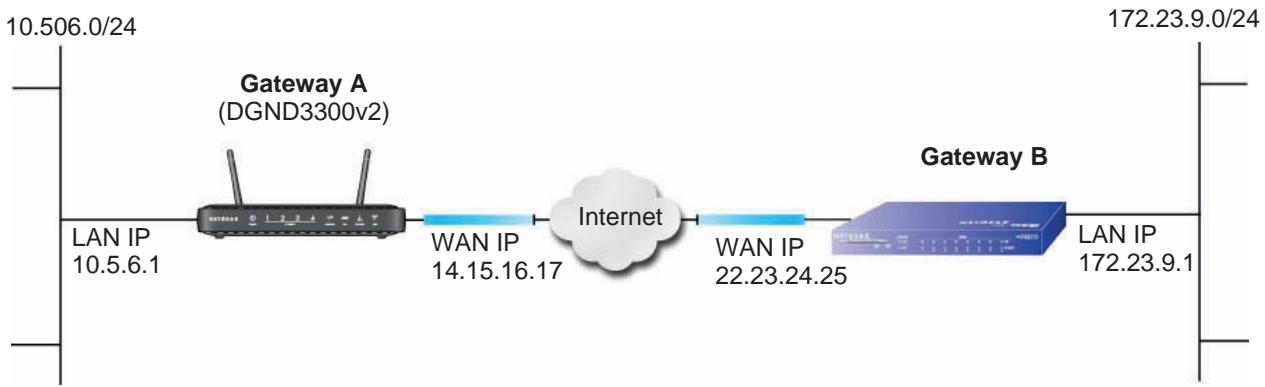
Figure 71. VPNC Example, Network Interface Addressing
Step-by-Step Configuration
- Use the VPN Wizard to configure Gateway A (DGND3300v2) for a gateway-to-gateway tunnel (see Setting Up a Gateway-to-Gateway VPN Configuration on page 90), being certain to use appropriate network addresses for the environment.
The LAN addresses used in this example are as follows:
| Unit | WAN IP | LAN IP | LAN Subnet Mask |
| DGND3300v2 | 14.15.16.17 | 10.5.6.1 | 255.255.255.0 |
| FVL328 | 22.13.24.25 | 172.23.9.1 | 255.255.255.0 |
a. For the connection name, enter toGW_B.
b. For the remote WAN's IP address, enter 22.23.24.25.
c. Enter the following:
IP Address. 172.23.9.1
- Subnet Mask. 255.255.255.0
d. In the Summary screen, click Done.
- Use the VPN Wizard to configure the Gateway B for a gateway-to-gateway tunnel (see Setting Up a Gateway-to-Gateway VPN Configuration on page 90), being certain to use appropriate network addresses for the environment.
a. For the connection name, enter toGW_A.
b. For the remote WAN's IP address, enter 14.15.16.17.
c. Enter the following:
IP Address. 10.5.6.1
- Subnet Mask. 255.255.255.0
d. In the Summary screen, click Done.
- On the Gateway B router menu, under VPN, select IKE Policies, and click the Edit button to display the IKE Policy Configuration screen:
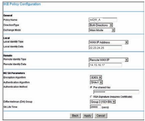
- On Gateway B router menu, under VPN, select VPN Policies, and click the Edit button to display the VPN - Auto Policy screen:
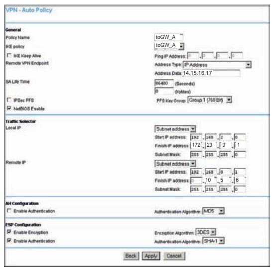
- Test the VPN tunnel by pinging the remote network from a PC attached to Gateway A (N300 wireless modem router).
a. Open the command prompt (select Start > Run > cmd).
b. Type ping 172.23.9.
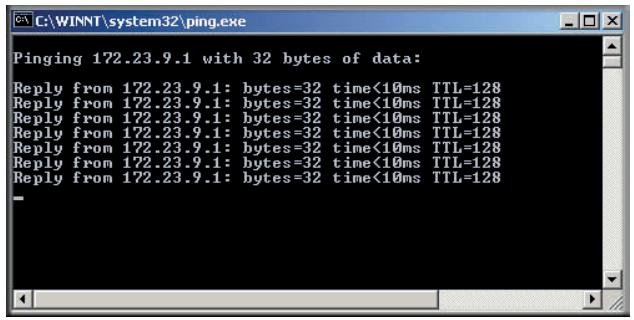
If the pings fail the first time, try the pings a second time.
N300 Wireless Modem Router with FQDN to Gateway B
This section is a case study on how to configure a VPN tunnel from a NETGEAR N300 wireless modem router to a gateway using a fully qualified domain name (FQDN) to resolve the public address of one or both routers. This case study follows the VPN Consortium interoperability profile guidelines (found at
http://www.vpnc.org/InteropProfiles/Interop-01.html).
Configuration Profile
The configuration in this section follows the addressing and configuration mechanics defined by the VPN Consortium. Gather the necessary information before you begin configuration.
Verify that the firmware is up to date, and that you have all the addresses and parameters to be set on both sides. Check that there are no firewall restrictions.
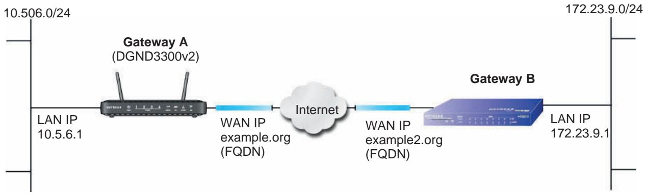
Figure 72. VPNC Example, Network Interface Addressing
Table 9. N300 Wireless Modem Router with FQDN to Gateway B Profile Summary
| VPN Consortium Scenario | Scenario 1 | |
| Type of VPN | LAN-to-LAN or gateway-to-gateway (not PC/client-to-gateway) | |
| Security scheme: | IKE with pre-shared secret/key (not certificate based) | |
| IP addressing: | ||
| NETGEAR-Gateway A | Fully qualified domain name (FQDN) | |
| NETGEAR-Gateway B | FQDN | |
Using a Fully Qualified Domain Name (FQDN)
Many ISPs provide connectivity to their customers using dynamic instead of static IP addressing. This means that a user's IP address does not remain constant over time, which presents a challenge for gateways attempting to establish VPN connectivity.
A Dynamic DNS (DDNS) service allows a user whose public IP address is dynamically assigned to be located by a host or domain name. It provides a central public database where information (such as email addresses, host names, and IP addresses) can be stored and retrieved. Now, a gateway can be configured to use a third-party service instead of a permanent and unchanging IP address to establish bidirectional VPN connectivity.
To use DDNS, you must register with a DDNS service provider. Some DDNS service providers include:
DynDNS: www.dyndns.org
- TZO.com: netgear.tzo.com
ngDDNS: ngddns.iego.net
In this example, Gateway A is configured using a sample FQDN provided by a DDNS service provider. In this case we established the hostname dgnd3300v2.dyndns.org for Gateway A using the DynDNS service. Gateway B uses the DDNS service provider when establishing a VPN tunnel.
To establish VPN connectivity, Gateway A must be configured to use Dynamic DNS, and Gateway B must be configured to use a DNS host name provided by a DDNS service provider to find Gateway A. Again, the following step-by-step procedures assume that you have already registered with a DDNS service provider and have the configuration information necessary to set up the gateways.
Step-by-Step Configuration
- Log in to Gateway A (your N300 wireless modem router) as described in Logging In to Your N300 Wireless Modem Router on page 8.
This example assumes that you have set the local LAN address as 10.5.6.1 for Gateway A and have set your own password.
- On Gateway A, configure the Dynamic DNS settings.
a. Under Advanced, select Dynamic DNS.
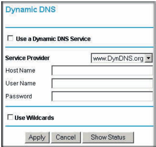
b. Fill in the fields with account and host name settings.
- Select the Use a Dynamic DNS Service check box.
In the Host Name field, type dgnd3300v2.dyndns.org. - In the User Name field, enter the account user name.
In the Password field, enter the account password.
c. Click Apply.
d. Click Show Status. The resulting screen should show Update OK: good:
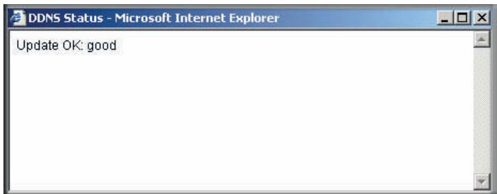
- On NETGEAR Gateway B, configure the Dynamic DNS settings. Assume a correctly configured DynDNS account.
a. From the main menu, select Dynamic DNS.
b. Select the DynDNS.org radio button.
The Dynamic DNS screen displays:
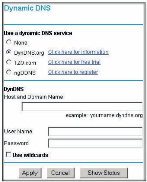
c. Fill in the fields with the account and host name settings.
In the Host and Domain Name field, enter fvI328.dyndns.org.
- In the User Name field, enter the account user name.
In the Password field, enter the account password.
d. Click Apply.
e. Click Show Status.
The resulting screen should show Update OK: good:
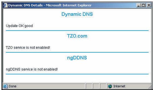
- Configure the N300 Wireless Dual Band ADSL2+ Modem Router DGND3300v2 as in the gateway-to-gateway procedures using the VPN Wizard (see Setting Up a Gateway-to-Gateway VPN Configuration on page 90), being certain to use appropriate network addresses for the environment.
The LAN addresses used in this example are as follows:
| Device | LAN IP Address | LAN Subnet Mask |
| DGND3300v2 | 10.5.6.1 | 255.255.255.0 |
| FVL328 | 172.23.6.1 | 255.255.255.0 |
a. For the connection name, enter toFVL328.
b. For the remote WAN's IP address, enter fvl328.dyndns.org.
c. Enter the following:
IP Address. 172.23.9.1
- Subnet Mask. 255.255.255.0
- Configure the FVL328 as in the gateway-to-gateway procedures for the VPN Wizard (see Setting Up a Gateway-to-Gateway VPN Configuration on page 90), being certain to use appropriate network addresses for the environment.
a. For the connection name, enter toDGND3300v2.
b. For the remote WAN's IP address, enter dgnd3300v2.dyndns.org.
c. Enter the following:
IP Address. 10.5.6.1
- Subnet Mask. 255.255.255.0
- Test the VPN tunnel by pinging the remote network from a PC attached to the N300 Wireless Dual Band ADSL2+ Modem Router DGND3300v2.
a. Open the command prompt (select Start > Run > cmd)
b. Type ping 172.23.9.1.

If the pings fail the first time, try the pings a second time.
Configuration Summary (Telecommuter Example)
The configuration in this section follows the addressing and configuration mechanics defined by the VPN Consortium. Gather the necessary information before you begin configuration.
Verify that the firmware is up to date, and make sure you have all the addresses and parameters to be set on both sides. Assure that there are no firewall restrictions.
Table 10. Configuration Summary (Telecommuter Example)
| VPN Consortium Scenario | Scenario 1 | |
| Type of VPN: | PC/client-to-gateway, with client behind NAT router | |
| Security scheme: | IKE with pre-shared secret/key (not certificate based) | |
| IP addressing: | ||
| Gateway | Fully qualified domain name (FQDN) | |
| Client | Dynamic | |
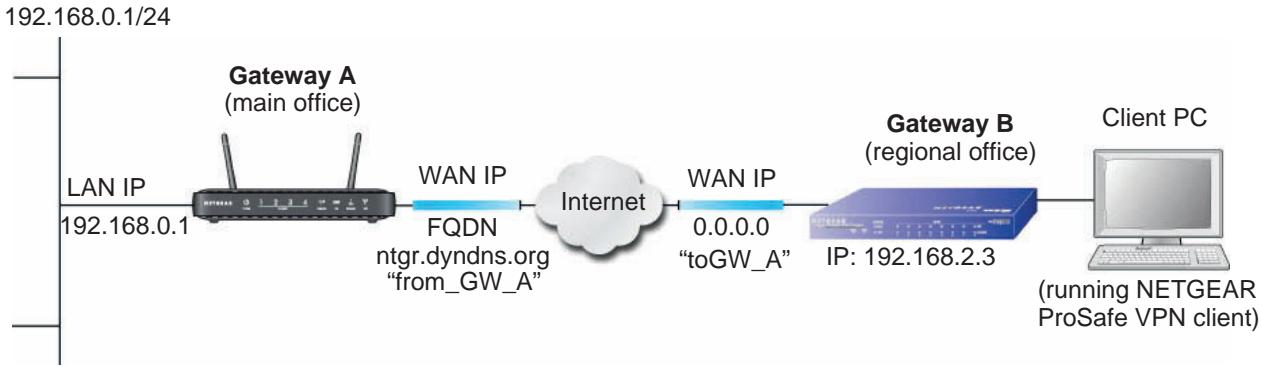
Figure 73. Telecommuter Example
Setting Up Client-to-Gateway VPN (Telecommuter Example)
Setting up a VPN between a remote PC running the NETGEAR ProSafe VPN client and a network gateway involves two steps, described in the following sections:
- Step 1: Configure Gateway A (VPN Router at Main Office) on page 159.
- Step 2: Configure Gateway B (VPN Router at Regional Office) on page 160 describes configuring the NETGEAR ProSafe VPN client endpoint.
Step 1: Configure Gateway A (VPN Router at Main Office)
- Log in to the VPN router. Select VPN Policies to display the VPN Policies screen. Click Add Auto Policy to proceed and enter the information.
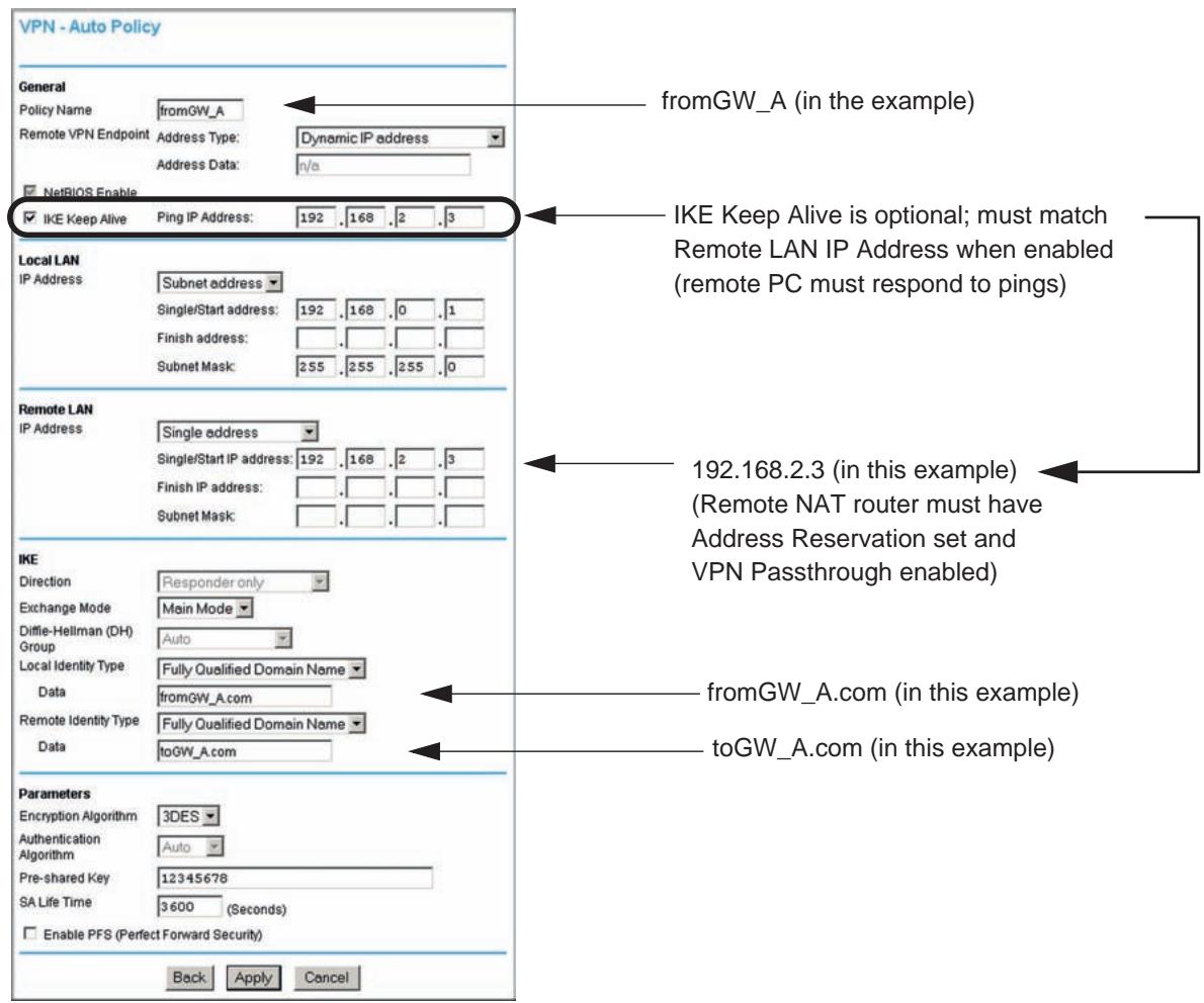
- Click Apply when you are finished to display the VPN Policies screen.
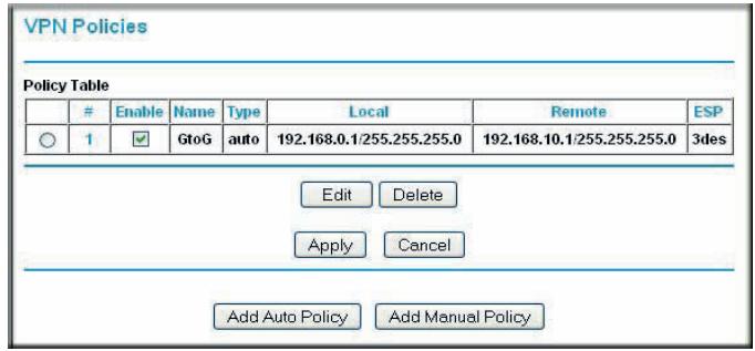
To view or modify the tunnel settings, select the radio button next to the tunnel entry, and then click Edit.
Step 2: Configure Gateway B (VPN Router at Regional Office)
This procedure assumes that the PC running the client has a dynamically assigned IP address.
The PC must have a VPN client program installed that supports IPSec (in this case study, the NETGEAR VPN ProSafe Client is used). Go to the NETGEAR website (www.netgear.com) for information about how to purchase the NETGEAR ProSafe VPN Client.
Note: Before installing the software, be sure to turn off any virus protection or firewall software you might be running on your PC.
- Install the NETGEAR ProSafe VPN Client on the remote PC, and then reboot.
a. You might need to insert your Windows CD to complete the installation.
b. If you do not have a modem or dial-up adapter installed in your PC, you might see the warning message stating "The NETGEAR ProSafe VPN Component requires at least one dial-up adapter be installed." You can disregard this message.
c. Install the IPSec component. You might have the option to install either the VPN adapter or the IPSec component or both. The VPN adapter is not necessary.
d. The system should show the ProSafe icon (S) in the system tray after you reboot.
e. Double-click the system tray icon to open the Security Policy Editor.
- Add a new connection.
a. Run the NETGEAR ProSafe Security Policy Editor program, and create a VPN connection.
b. From the Edit menu of the Security Policy Editor, select Add > Connection. A New Connection listing appears in the list of policies.
c. Rename the new connection to match the connection name you entered in the VPN settings of Gateway A. Choose connection names that make sense to the people using and administrating the VPN.
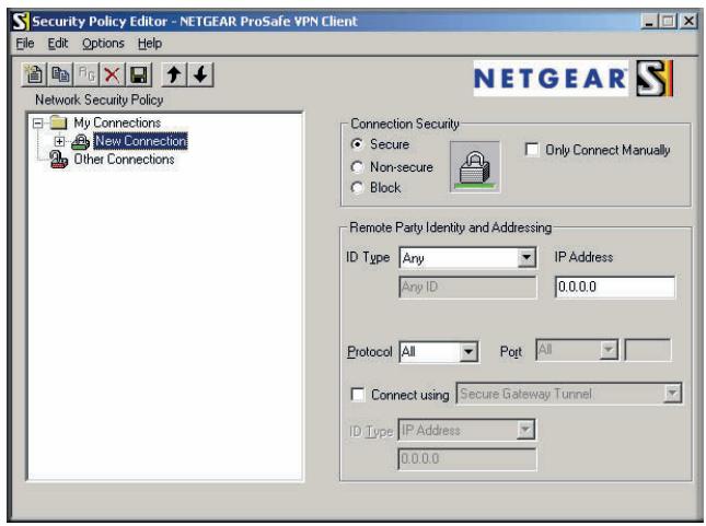
Note: In this example, the connection name on the client side of the VPN tunnel is toGW_A. It does not have to match the VPN_client connection name used on the gateway side of the VPN tunnel because connection names do not affect how the VPN tunnel functions.
d. In the Connection Security section, select Secure.
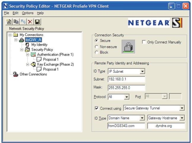
e. In the ID Type drop-down list, select IP Subnet.
f. In this example, in the Subnet field, type 192.168.0.1 as the network address of the N300 wireless modem router.
g. In the Mask field, enter 255.255.255.0 as the LAN subnet mask of the N300 wireless modem router.
h. In the Protocol drop-down list, select All to allow all traffic through the VPN tunnel.
i. Select the Connect using Secure Gateway Tunnel check box.
j. In the ID Type drop-down list, select Domain Name, and enter fromGW_A.com (in this example).
k. Select Gateway Hostname and enter ntgr.dyndns.org (in this example).
- Configure the security policy in the N300 wireless modem router software.
a. In the Network Security Policy list, expand the new connection by double-clicking its name or clicking the + symbol. My Identity and Security Policy appear below the connection name.
b. Click Security Policy to show the Security Policy screen.
c. In the Select Phase 1 Negotiation Mode group, select the Main Mode radio button.
- Configure the VPN client identity.
In this step, you provide information about the remote VPN client PC. You must provide the pre-shared key that you configured in the N300 wireless modem router and either a fixed IP address or a fixed virtual IP address of the VPN client PC.
a. In the Network Security Policy list on the left side of the Security Policy Editor window, click My Identity.
b. In the Select Certificate list, select None.
c. In the ID Type list, select Domain Name, and enter toGW_A.com (in this example).
d. In the Virtual Adapter list, select Disabled.
e. In the Internet Interface section, select Intel PRO/100VE Network Connection (in this example; your Ethernet adapter might be different) in the Name list, and then in the IP Addr list, enter 192.168.2.3 (in this example).
f. Click the Pre-Shared Key button.
g. In the Pre-Shared Key screen, click Enter Key. Enter the N300 Wireless Dual Band ADSL2+ Modem Router DGND3300v2's pre-shared key and click OK. In this example, 12345678 is entered, though the screen shows asterisks. This field is case-sensitive.
- Configure the VPN Client Authentication Proposal.
In this step, you provide the type of encryption (DES or 3DES) to be used for this connection. This selection must match your selection in the VPN router configuration.
a. In the Network Security Policy list on the left side of the Security Policy Editor window, expand the Security Policy heading by double-clicking its name or clicking the + symbol.
b. Expand the Authentication subheading by double-clicking its name or clicking the + symbol. Then select Proposal 1 below Authentication.
c. In the Authentication Method drop-down list, select Pre-Shared Key.
d. In the Encrypt Alg drop-down list, select the type of encryption. In this example, use Triple DES.
e. In the Hash Alg drop-down list, select SHA-1.
f. In the SA Life drop-down list, select Unspecified.
g. In the Key Group drop-down list, select Diffie-Hellman Group 2.
- Configure the VPN Client Key Exchange Proposal.
In this step, you provide the type of encryption (DES or 3DES) to be used for this connection. This selection must match your selection in the VPN router configuration.
a. Expand the Key Exchange subheading by double-clicking its name or clicking the + symbol. Then select Proposal 1 below Key Exchange.
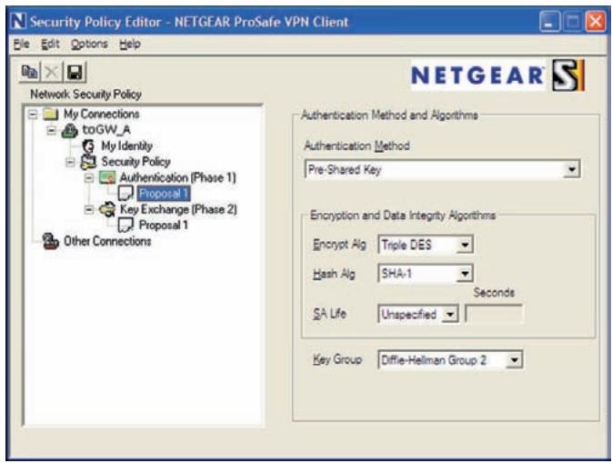
b. In the SA Life drop-down list, select Unspecified.
c. In the Compression drop-down list, select None.
d. Select the Encapsulation Protocol (ESP) check box.
e. In the Encrypt Alg drop-down list, select the type of encryption. In this example, use Triple DES.
f. In the Hash Alg drop-down list, select SHA-1.
g. In the Encapsulation drop-down list, select Tunnel.
h. Leave the Authentication Protocol (AH) check box cleared.
- Save the VPN client settings.
From the File menu at the top of the Security Policy Editor window, select Save.
After you have configured and saved the VPN client information, your PC automatically opens the VPN connection when you attempt to access any IP addresses in the range of the remote VPN router's LAN.
- Check the VPN connection.
To check the VPN connection, you can initiate a request from the remote PC to the VPN router's network by using the Connect option in the N300 wireless modem router screen:
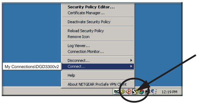
Right-click the system tray icon to open the pop-up menu.
Since the remote PC has a dynamically assigned WAN IP address, it must initiate the request.
a. Right-click the system tray icon to open the pop-up menu.
b. Select Connect to open the My Connections list.
c. Select toDGND3300v2.
The N300 wireless modem router reports the results of the attempt to connect. Once the connection is established, you can access resources of the network connected to the VPN router.
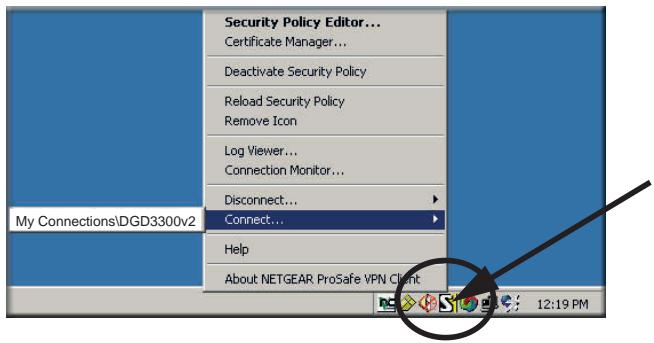
Right-click the system tray icon to open the pop-up menu.
To perform a ping test using this example, start from the remote PC:
a. Establish an Internet connection from the PC.
b. On the Windows taskbar, click the Start button, and then select Run.
c. Type ping -t 192.168.0.1, and then click OK.
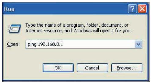
This causes a continuous ping to be sent to the VPN router. Within 2 minutes, the ping response should change from timed out to reply.
C:\>ping 192.168.0.1
Pinging 192.168.0.1 with 32 bytes of data:
Reply from 192.168.0.1: bytes=32 time<1ms TTL=64
Reply from 192.168.0.1: bytes=32 time<1ms TTL=64
Reply from 192.168.0.1: bytes=32 time=1ms TTL=64
Once the connection is established, you can open the browser on the PC and enter the LAN IP address of the VPN router. After a short wait, you should see the login screen of the VPN router (unless another PC already has the VPN router management interface open).
Note: You can use the VPN router diagnostics to test the VPN connection from the VPN router to the client PC. To do this, select Diagnostics on the N300 wireless modem router main menu.
Monitoring the VPN Tunnel (Telecommuter Example)
To view information about the progress and status of the VPN client connection, open the Log Viewer. In Windows, click Start, and select Programs > N300 Wireless Dual Band ADSL2+ Modem Router DGND3300v2 > Log Viewer.
Note: Use the active VPN tunnel information and pings to determine whether a failed connection is due to the VPN tunnel or some reason outside the VPN tunnel.
The Connection Monitor screen displays:
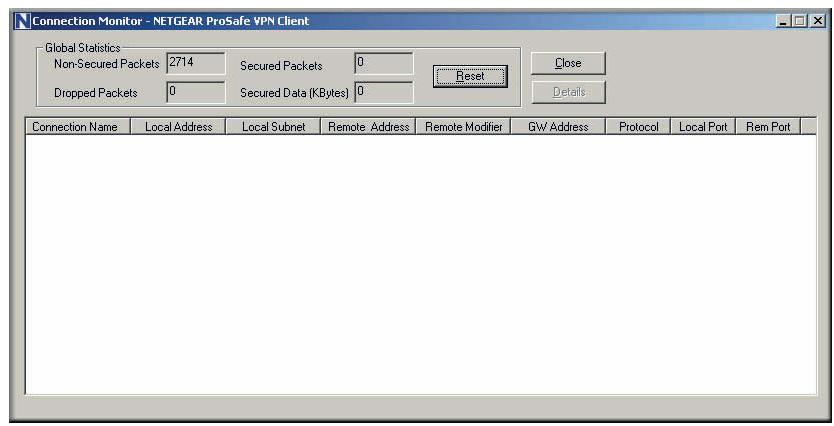
While the connection is being established, the connection name listed in this screen shows SA before the name of the connection. When the connection is successful, the SA changes to the yellow key symbol.
Note: While your PC is connected to a remote LAN through a VPN, you might not have normal Internet access. If this is the case, you need to close the VPN connection to have normal Internet access.
Viewing the VPN Router's VPN Status and Log Information
To view information about the status of the VPN client connection, open the VPN router's VPN Status screen:
- On the N300 wireless modem router main menu, select Router Status, and then click the VPN Status button. The VPN Status/Log screen displays:
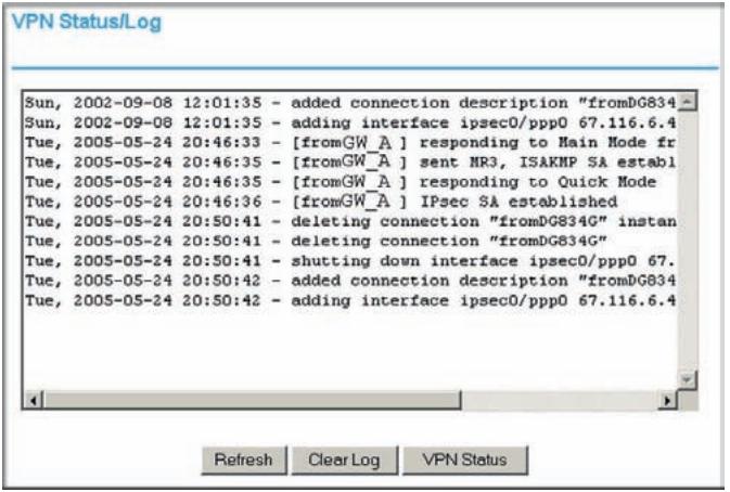
- To view the VPN tunnels status, click VPN Status.

Notification of Compliance
NETGEAR Wireless Routers, Gateways, APs
D
Regulatory Compliance Information
This section includes user requirements for operating this product in accordance with National laws for usage of radio spectrum and operation of radio devices. Failure of the end-user to comply with the applicable requirements may result in unlawful operation and adverse action against the end-user by the applicable National regulatory authority.
Note: This product's firmware limits operation to only the channels allowed in a particular Region or Country.
Therefore, all options described in this user's guide may not be available in your version of the product.
FCC Requirements for Operation in the United States
FCC Information to User
This product does not contain any user serviceable components and is to be used with approved antennas only. Any product changes or modifications will invalidate all applicable regulatory certifications and approvals
FCC Guidelines for Human Exposure
This equipment complies with FCC radiation exposure limits set forth for an uncontrolled environment. This equipment should be installed and operated with minimum distance of 20~cm between the radiator and your body.
This transmitter must not be co-located or operating in conjunction with any other antenna or transmitter.
FCC Declaration of Conformity
We, NETGEAR, Inc., 350 East Plumeria Drive, Santa Clara, CA 95134, declare under our sole responsibility that the NETGEAR® N300 Wireless Dual Band ADSL2+ Modem Router DGND3300v2 complies with Part 15 Subpart B of FCC CFR47 Rules. Operation is subject to the following two conditions:
- This device may not cause harmful interference, and
- This device must accept any interference received, including interference that may cause undesired operation.
FCC Radio Frequency InterferenceWarnings & Instructions
This equipment has been tested and found to comply with the limits for a Class B digital device, pursuant to Part 15 of the FCC Rules. These limits are designed to provide reasonable protection against harmful interference in a residential installation. This equipment uses and can radiate radio frequency energy and, if not installed and used in accordance with the instructions, may cause harmful interference to radio communications. However, there is no guarantee that interference will not occur in a particular installation. If this equipment does cause harmful interference to radio or television reception, which can be determined by turning the equipment off and on, the user is encouraged to try to correct the interference by one or more of the following methods:
- Reorient or relocate the receiving antenna.
- Increase the separation between the equipment and the receiver.
- Connect the equipment into an electrical outlet on a circuit different from that which the radio receiver is connected.
- Consult the dealer or an experienced radio/TV technician for help.
FCC Caution
- Any changes or modifications not expressly approved by the party responsible for compliance could void the user's authority to operate this equipment.
- This device complies with Part 15 of the FCC Rules. Operation is subject to the following two conditions: (1) This device may not cause harmful interference, and (2) this device must accept any interference received, including interference that may cause undesired operation.
- For product available in the USA market, only channel 1~11 can be operated. Selection of other channels is not possible.
- This device and its antenna(s) must not be co-located or operation in conjunction with any other antenna or transmitter.
Canadian Department of Communications Radio Interference Regulations
This digital apparatus, (NETGEAR® N300 Wireless Dual Band ADSL2+ Modem Router DGND3300v2), does not exceed the Class B limits for radio-noise emissions from digital apparatus as set out in the Radio Interference Regulations of the Canadian Department of Communications.
Interference Reduction Table
| Household Appliance | Recommended Minimum Distance between NETGEAR equipment and household appliance to reduce interference (in feet and meters) |
| Microwave ovens | 30 feet / 9 meters |
| Baby Monitor - Analog | 20 feet / 6 meters |
| Baby Monitor - Digital | 40 feet / 12 meters |
| Cordless phone - Analog | 20 feet / 6 meters |
| Cordless phone - Digital | 30 feet / 9 meters |
| Bluetooth devices | 20 feet / 6 meters |
| ZigBee | 20 feet / 6 meters |
Europe - EU Declaration of Conformity

Marking with the above symbol indicates compliance with the Essential Requirements of the R&TTE Directive of the European Union (1999/5/EC).
This equipment meets the following conformance standards:
EN300 328 (2.4Ghz), EN301 489-17, EN301 893 (5Ghz), EN60950-1
- This device is a 2.4 GHz wideband transmission system (transceiver), intended for use in all EU member states and EFTA countries, except in France and Italy where restrictive use applies.
- In Italy, the end-user should apply for a license at the national spectrum authorities in order to obtain authorization to use the device for setting up outdoor radio links and/or for supplying public access to telecommunications and/or network services.
- This device may not be used for setting up outdoor radio links in France and in some areas the RF output power may be limited to 10mW EIRP in the frequency range of 2454 - 2483.5 MHz. For detailed information the end-user should contact the national spectrum authority in France.
- For complete DoC, visit the NETGEAR EU Declarations of Conformity website at:
http://kb.netgear.com/app/answers/detail/a_id/11621/
EDOC in Languages of the European Community
| Cesky [Czech] | NETGEAR Inc. tímtó prohlášuje, ze tento Radiolan je ve shode se základními požadavya dalísmi príslužnými ustanoveními smernice 1999/5/ES. |
| Dansk [Danish] | Undertegnede NETGEAR Inc. erkrær herved, at følgende udstyr Radiolan overholder de væsentlige krav og øvrige relevante krav i direktiv 1999/5/EF. |
| Deutsch [German] | Hiermit erklart NETGEAR Inc., dass sich das Gerät Radiolan in Übereinstimmung mit den grundlegenden Anforderungen und den übrigen einschlögigen Bestimmungen der Richtlinie 1999/5/EG befindet. |
| Eesti [Estonian] | Käesolevaga kinnitab NETGEAR Inc. seadme Radiolan vastavust direktivi 1999/5/Eü põhinöutele ja nimetatud direktiviist tulenevatele teistele asjakohastele sâtetele. |
| English | Hereby, NETGEAR Inc., declares that this Radiolan is in compliance with the essential requirements and other relevant provisions of Directive 1999/5/EC. |
| Espanol [Spanish] | Por medio de la presente NETGEAR Inc. declara que el Radiolan cumple con los requisitos esencias y cualesquiera除外as dispositions aplicables o exigibles de la Directiva 1999/5/CE. |
| Éλληνική [Greek] | ME THN ΠΑΝΟΥΣA NETGEAR Inc. ΔΗλΩNEI OTI Radiolan ΣΥΜΜΟΦΩNETAI ΠΙΟΣ TΙΣ OΥΣΙΟΔΕΙΣ ΑΝΑΙΤΗΣΕΙΣ KAI TΙΣ ΑΟΙΝΕΣ ΣΧΕΤΙΚΕΣ ΔΙΑΤΑΕΙΣ ΘΗ ΕΔΗΓΙΑΣ 1999/5/EK. |
| François [French] | Par laprésente NETGEAR Inc. déclare que l'appareil Radiolan est conforme aux exigences essentielles et aux autres dispositions pertinentes de la directive 1999/5/CE. |
| Italiano [Italian] | Con la presente NETGEAR Inc. dichiar che questo Radiolan è conforme ai requisiti essenziali ed alle autres dispositions pertinenti stabilite alla direttiva 1999/5/CE. |
| Latviski [Latvian] | Ar šo NETGEAR Inc. deklare, ka Radiolan atbilst Direktivas 1999/5/EK būtiskajām prisībām un citiem ar to saistītajiem noteikumiem. |
| Lietuvić [Lithuanian] | Šiuo NETGEAR Inc. deklaruoja, kad šis Radiolan atitinka esminius reikalavimus ir kitas 1999/5/EB Direktyvos nuostatas. |
| Nederlands [Dutch] | Hierbij verklaart NETGEAR Inc. dat het toestel Radiolan in overeenstemming is met de essentiële eisen en de andere relevante bepalingen van richtlijn 1999/5/EG. |
| Mali [Maltese] | Hawnhekk, NETGEAR Inc., jiddikjara li dan Radiolan jikkonforma mal-htigjiet essenjali u ma provvedimenti ohrajn relevanti li hemm fid-Dirrettiva 1999/5/EC. |
| Magyar [Hungarian] | Alulírott, NETGEAR Inc. nyilatkozom, hogy a Radiolan megfelel a vonaţkoź alapvető követelményeknek és az 1999/5/EC irányelv egyéb elöírsainak. |
| Polski [Polish] | Niniejszym NETGEAR Inc. oswiadcza, ze Radiolan jest zgodny z kasadniczymi wymogami oraz pozostalymi stosownymi postanowieniami Dyrektywy 1999/5/EC. |
| Portuguès [Portuguese] | NETGEAR Inc. declara que este Radiolan está conforme com os requisitos essenciais e outras dispositions da Directiva 1999/5/CE. |
| Slovensko [Slovenian] | NETGEAR Inc. izjavlja, da je ta Radiolan v skladu z bistvenimi zahtevami in ostalimi relevantnimi dolovi direktive 1999/5/ES. |
| Slovensky [Slovak] | NETGEAR Inc. týmto vyhlasuje, ze Radiolan splína základné požiadavky a větky príslůné ustanovenia Smernice 1999/5/ES. |
| Suomi [Finnish] | NETGEAR Inc. vakuuttaa täten että Radiolan typpinen laite on direktiivin 1999/5/EY oleellisten vaatimusten ja sitä koskevien direktiivin muiden ehtojen mukainen. |
| Svenska [Swedish] | Härmed intygar NETGEAR Inc. attenna Radiolan står I overensstättmelse med deväsentliga egenskapskrav och övriga relevanta beställmelser som framgår av direktiv 1999/5/EG. |
| Íslenska [Icelandic] | Hér með lásir NETGEAR Inc. yfirþvi að Radiolan erí samræmi við grunnkröfur og aðrar kröfur, sem geröar eruí tilskipun 1999/5/EC. |
| Norsk [Norwegian] | NETGEAR Inc. erklærer herved at utstyret Radiolan er i samsvar med de grunnleggende krav og övrige relevante krav i direktiv 1999/5/EF. |
This appendix provides links to reference documents you can use to gain a more complete understanding of the technologies used in your NETGEAR product.
| Document | Link |
| TCP/IP Networking Basics | http://documentation.netgear.com/reference/enu/tcpip/index.htm |
| Wireless Networking Basics | http://documentation.netgear.com/reference/enu/wireless/index.htm |
| Preparing Your Network | http://documentation.netgear.com/reference/enu/wsdhcp/index.htm |
| Virtual Private Networking Basics | http://documentation.netgear.com/reference/enu/vpn/index.htm |
| Glossary | http://documentation.netgear.com/reference/enu/glossary/index.htm |
In addition, you can find initial setup instructions for your N300 wireless modem router in the N300 Wireless Dual Band ADSL2+ Modem Router Installation Guide.
Index
Numerics
802.11 protocol mode 19
A
access
blocking 37, 44
remote 59
restricting 29
restricting by MAC address 22, 35
viewing logs 46
access points 125
account name 53
address reservation 115
ADSL settings 14
advanced USB storage settings 69
advanced WPS settings 27
advertisement period 136
attached devices 57
authentication proposal 86, 87
authentication, required by mail server 48
Auto Policy to configure VPN tunnels 101
available wireless stations 36
B
backing up configuration file 58
backing up, transfer time 131
bandwidth, optimizing 132
base station, setting up 127
Basic Settings screen 12
blocking access 37, 44
broadband Internet 130
broadcast status 55
bus speeds 65
C
cables, checking 138
channels 17
channels, wireless port 54
client-to-gateway VPN tunnels 77
compliance, wireless 168
configuration file 57, 58
configuring
ADSL settings 14
DMZ server 117, 119
Dynamic DNS 116
email alerts 47
firewall rules 38
firmware upgrades 50
ISP settings 10
LAN IP services 112
log notifications 47
logs of web access 46
MTU size 134
parental controls 32
portforwarding41
port triggering 43
QoS 119
remote management 60
repeater unit 128
security policy 85
static routes 123
UPnP 135
USB storage 67, 69, 74
using the Setup Manual 7
using the Smart Wizard 7
using WPS 24
VPN tunnels 78, 79, 80, 90, 153
WEP security 20
wireless guest networks 30
wireless repeating 125
wireless settings 18
WPA security 22
WPA2 security 22
connection status settings 55
connection types 130
CTS/RTS threshold 30
D
data packets, fragmented 134
date and time, troubleshooting 144
daylight savings time 49, 144
deactivating VPN tunnels 98, 99
default DMZ server 119
default factory settings 58, 147, 148
deleting
configuration 58
VPN tunnels 100
device name 57
devices attached 57
DHCP server 114
DHCP setting 54
diagnostics 59
Digital Living Network Alliance (DLNA) 72
disabling
automatic WAN connection 118
firewall 13, 118
net address translation (NAT) 13
router PIN 27
security 20
SIP ALG 118
SSID broadcast 29
UPnP 136
wireless client association 127
wireless router radio 29
disabling WMM QoS 120
disablingDHCP server function 128
DMZ server 119
DNS addresses, troubleshooting 142
DNS server 13
documents, reference 172
Domain Name Server (DNS) addresses 54
Dynamic DNS 116
DynDNS.org 116
E
emailing logs 47
encryption algorithm 87
encryption keys 22
erasing configuration 58
Ethernet cables, checking 138
Ethernet light, troubleshooting and 140
Ethernet MAC address. See MAC addresses
F
factory default settings 58, 147, 148
file and printer sharing 74
file sharing 65
files, sharing 66
filtering 32
firewall rules 38
firmware version 53
folders, networks
creating 71
editing 68
fragmentation threshold 30
fragmented data packets 134
fully qualified domain name (FQDN), configuring VPN
tunnels using 153
G
gateway-to-gateway VPN tunnels 77, 90
Gigabit Ethernet 131
guest networks 30
H
host name 12, 53, 57
1
IKE protocol 101
Instant Messaging, disabling 39
Interface specifications 150
interference, reducing 133
Internet connection
default settings 148
troubleshooting 141
Internet light, troubleshooting and 140
Internet port, status 54
Internet services, blocking access 44
Internet sites, blocking access 37
Internet traffic statistics 63
interval, poll 56
IP addresses
auto-generated 140
current 54
dynamic 116
RADIUS server 23
reserved 115
WAN 141
IP subnet mask 54
K
keep-alive, IKE 103
keys, encryption 22
keywords,blockingby37
L
LAN path, troubleshooting 143
LAN port settings 54
LAN setup 112
large files, sharing 66
LEDs
Ethernet 140
Internet 140
Power 138
Wireless 140
Live Parental Controls 32
local network, default settings 148
Log Viewer 89
logging in and out 8
login settings 148
logs
sending 47
time-stamping entries 49
viewing 46
M
MAC addresses
attached devices 57
current 54
restricting access by 35
troubleshooting 144
mail server, outgoing 48
managing router remotely 59
manual software upgrade 51
manually configuring VPN policies 109
MD5 authentication 104
media server 72
metric value 125
Microsoft Network 74
mode, communication 55
modes
802.11 protocol 19
preamble 30
Up to 145 Mbps at 2.4 GHz 19, 31
Up to 145 Mbps at 5 GHz and 54 Mbps at 2.4 GHz
19, 31
Up to 270 Mpbs 31
Up to 300 Mbps at 2.4 GHz 19
Up to 300 Mbps at 5 GHz and 54 Mbps at 2.4 GHz 19, 30
MTU size 134
multicasting 114
multiple input, multiple output (MIMO) 130
N
NAT (Network Address Translation) 119
NETGEAR ProSafe VPN Client 83
network folders
creating 71
editing 68
Network Time Protocol (NTP) 49, 144
networks
correct settings, checking 138
restarting 138
non-WPS clients, adding 28
0
obstructions, connecting through 131
OpenDNS 32
optimizing
bandwidth 132
performance 133
outgoing mail server 48
P
packets, fragmented 134
parental controls 32
password, restoring 147
path, testing 143
performance, optimizing 133
photos, sharing 66
PIN, adding WPS client using 25
ping 89, 142, 165
placement, router 133
poll interval 56
port filtering 44
portforwarding41
port numbers 44
port status 56
port triggering 43
Power light, troubleshooting and 138
Powerline HD products 131
PPPoE (PPP over Ethernet) 142
Preamble mode 30
primary DNS server 13
printing, storing files for 66
Q
Quality of Service (QoS) 119
R
radio, wireless 29
RADIUS server 23
range, router 133
ReadyDLNA 72
ReadyShare 72
reducing interference 133
reference documents 172
releasing connection status 56
remote devices, testing path 143
remote management 59
renewing connection status 55
repeater units 128
requirements, speed 131
reserved IP addresses 115
restarting network 138
restoring default factory settings 58, 147, 148
restrict access by MAC address 22
restricting access 22, 29, 35
RIP (Router Information Protocol) 114
router status, viewing 52
rules, firewall38
S
sample network, figure 133
security association (SA) 78
security policy, configuring 85
service numbers 45
services,blocking 44
setting time 49
settings, default 58, 147, 148
SHA-1 authentication 104
sharing files 65, 66
SMTP server 48
software, upgrading 50
specifications, technical 147
speed requirements 131
SSID
allow broadcast 29
broadcast status 55
static routes 123
status
connection 55
status, router, viewing 52
streaming video and audio 131
subset mask 54
system up time 56
T
TCP/IP network, troubleshooting 142
technical specifications 147
Technical Support 2
time of day, troubleshooting 144
time to live, advertisement 136
time, setting 49
trademarks 2
traffic control 62
traffic counter 62
traffic meter 61
traffic status 63
troubleshooting 137, 141
trusted user 38
U
Universal Plug and Play (UPnP) 72, 135
up time, system 56
Up to 145 Mbps at 2.4 GHz mode 19, 31
Up to 145 Mbps at 5 GHz and 54 Mbps at 2.4 GHz mode 19, 31
Up to 270 Mpbs mode 31
Up to 300 Mbps at 2.4 GHz mode 19
Up to 300 Mbps at 5 GHz and 54 Mbps at 2.4 GHz mode 19, 30
updating
firmware 8
router software 50
USB drive
requirements 65
unmounting 72
USB storage 64
V
viewing
attached devices 57
logs 46
router status 52
VPN Auto Policy 101, 106, 107
VPN client 83
VPN Log Viewer 89, 166
VPN Manual Policy 109
VPN network connections 101
VPN tunnels
activating 94, 96
client-to-gateway 77
configuring 153
control 94
deactivating 98, 99
deleting 100
gateway-to-gateway 77, 90
monitoring 166
special setup 100
status 97
VPN Wizard 92, 93
VPNs 77
overview 76
pinging 165
planning 78
status 94, 167
W
WAN IP address, troubleshooting 141
WAN setup 117
warning
DMZ servers 119
protecting against unauthorized access 15
reboot process 58
unmount USB drive 72
uploading firmware 51, 52
wireless repeating function 125
WEP, configuring 20
wireless access points 17
wireless card, setting up 145
wireless clients, adding 25, 27
wireless connection type 130
Wireless Distribution System (WDS) 125, 126
Wireless light, troubleshooting and 140
wireless network name 55
Wireless port settings 54
wireless radio 29, 55
wireless repeating 125, 126
base station 127
repeater unit 128
wireless repeating function 125, 126
wireless security 26
wireless settings, checking for correct 138
wireless stations 36
wireless, guest network 30
wireless, manually configuring settings 18
wireless, range and interference 16
WPA, configuring 22
WPS clients, adding 25, 27