
GFX-8 - Multi-effets pour guitare ZOOM - Notice d'utilisation et mode d'emploi gratuit
Retrouvez gratuitement la notice de l'appareil GFX-8 ZOOM au format PDF.

| Type de produit | Processeur multi-effets pour guitare |
| Marque / Modèle | ZOOM GFX-8 |
| Dimensions (L × H × P) | 455 × 203 × 80 mm |
| Poids | 3,6 kg |
| Alimentation | Adaptateur secteur 12 V AC fourni (AD-0008) |
| Nombre d'effets | 69 (67 effets + simulateur d'ampli + ZNR) |
| Modules d'effets simultanés | Jusqu'à 9 (DRIVE, EQ, MOD, DLY/REV + ZNR + simulateur d'ampli) |
| Mémoire de patches | 240 patches (80 utilisateur + 160 préréglés) |
| Sampler intégré | Temps d'enregistrement max. 25 secondes, vitesse de lecture variable |
| Fonction Jam Play | Enregistrement de 12 secondes avec lecture normale, inversée ou scratch |
| MIDI | Entrée et sortie MIDI (prise IN/OUT), canal 1-16 |
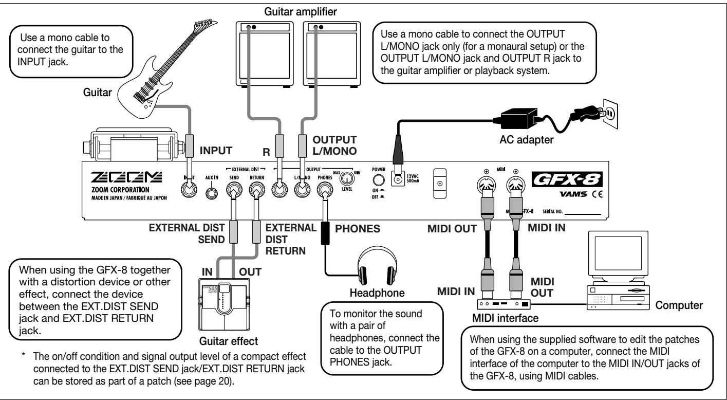
| Connectique | Entrée guitare, retour externe, AUX IN (mini-jack stéréo), sorties ligne L/MONO et R, sortie casque, send/return distortion externe |
| Réglages principaux | Expression pédale, commutateurs au pied, Easy Edit, mode manuel, accordeur chromatique, RTM |
| Nettoyage et entretien | Chiffon doux et sec ; ne pas utiliser de solvants ou produits abrasifs |
| Précautions de sécurité | Utiliser uniquement l'adaptateur fourni, éviter températures extrêmes, humidité, chocs |
| Réparabilité / Pièces détachées | Ne pas ouvrir le boîtier ; aucune pièce réparable par l'utilisateur ; contacter un service agréé |
| Garantie | Consulter la carte de garantie fournie |
FOIRE AUX QUESTIONS - GFX-8 ZOOM
Questions des utilisateurs sur GFX-8 ZOOM
0 question sur cet appareil. Repondez a celles que vous connaissez ou posez la votre.
Poser une nouvelle question sur cet appareil
Téléchargez la notice de votre Multi-effets pour guitare au format PDF gratuitement ! Retrouvez votre notice GFX-8 - ZOOM et reprennez votre appareil électronique en main. Sur cette page sont publiés tous les documents nécessaires à l'utilisation de votre appareil GFX-8 de la marque ZOOM.
MODE D'EMPLOI GFX-8 ZOOM
#
GFX-8
GUITAR EFFECTS PROCESSOR
Operation Manual
CONTENTS
Safety and Usage Precautions 2
Introduction 3
Naming of Parts 4
Top Panel 4
Rear Panel 4
Terms Used in This Manual 5
Getting Connected 6
Connection Example (1) 6
Connection Example (2) 6
Connection Example (3) 6
Preparations 7
Power Up 7
Setting up the Amp Simulator 7
Quick Guide (Trying Out the Unit) 8
Listening to Patches (Play Mode Operation) 10
Panel Indication in Play Mode 10
Selecting a Patch 10
Using the Easy Edit Function 11
Using the Bypass (Mute)/Tuner Function 12
Adjusting the Reference Pitch of the Tuner 13
Switching Modules On and Off During Play (Manual Mode) 13
Changing the Sound of a Patch (Edit Mode) 14
Basic Edit Mode Steps 14
Edit Mode Shortcut (1) 16
Edit Mode Shortcut (2) 16
Creating Custom Distortion 17
Storing Custom Module Settings 18
Storing and Copying Patches (Store Mode Operation) 18
Effects and Parameters 19
DRIVE Module 19
ZNR/EQ (Zoom Noise Reduction/Equalizer) Module 20
MOD (Modulation) Module 21
DLY/REV (Delay/Reverb) module 25
SFX Effects 27
TOTAL Module 29
Using RTM 30
Using the CONTROL Switch 31
Using the Jam Play Feature 32
Using the Sampler 34
MIDI Usage Examples 35
BasicMIDI Send/Receive Settings 35
Switching GFX-8 Patches From an External Unit 35
Controlling External Devices in Conjunction With GFX-8
Patch Switching 37
Remote Control Using GFX-8 38
BulkDump 39
Bulk Load 40
Supplied Software 40
Other Functions 41
All Initialize/Factory Recall 41
Trying Out the Factory Default Patches
(Self Introduction Function) 41
Adjusting the Expression Pedal 41
Disabling the Bypass/Mute Function 41
Troubleshooting 42
GFX-8 Specifications 42
MIDI Implementation Chart 43
Safety and Usage Precautions
USAGE AND SAFETY PRECAUTIONS
In this manual, symbols are used to highlight warnings and cautions for you to read so that accidents can be prevented. The meanings of these symbols are as follows:

This symbol indicates explanations about extremely dangerous matters. If users ignore this symbol and handle the device the wrong way, serious injury or death could result.

This symbol indicates explanations about dangerous matters. If users ignore this symbol and handle the device the wrong way, bodily injury and damage to the equipment could result.
Please observe the following safety tips and precautions to ensure hazard-free use of the GFX-8.
Power requirements

- The GFX-8 is powered by the supplied AC adapter.
- To prevent malfunction and safety hazards, Do not use any other kind of AC adapter.
- When using the GFX-8 in an area with a different line voltage, please consult your local ZOOM distributor about acquiring a proper AC adapter.
- Environment

Avoid using your GFX-8 in environments where it will be exposed to:
- Extreme temperature
High humidity or moisture - Excessive dust or sand
- Excessive vibration or shock
Handling

Since the GFX-8 is a precision electronic device, avoid applying excessive force to the switches and buttons. Also take care not to drop the unit, and do not subject it to shock or excessive pressure.
- Alterations

Never open the case of the GFX-8 or attempt to modify the product in any way since this can result in damage to the unit.
- Connecting cables and input and output jacks

You should always turn off the power to the GFX-8 and all other equipment before connecting or disconnecting any cables. Also make sure to disconnect all cables and the AC adapter before moving the GFX-8.
Usage Precautions
- Electrical interference
For safety considerations, the GFX-8 has been designed to provide maximum protection against the emission of electromagnetic radiation from inside the device, and protection from external interference. However, equipment that is very susceptible to interference or that emits powerful electromagnetic waves should not be placed near the GFX-8, as the possibility of interference cannot be ruled out entirely.
With any type of digital control device, the GFX-8 included, electromagnetic interference can cause malfunctioning and can corrupt or destroy data. Care should be taken to minimize the risk of damage.
- Cleaning
Use a soft, dry cloth to clean the GFX-8. If necessary, slightly moisten the cloth. Do not use abrasive cleanser, wax, or solvents (such as paint thinner or cleaning alcohol), since these may dull the finish or damage the surface.
Please keep this manual in a convenient place for future reference.
Thank you for selecting the ZOOM GFX-8 (hereafter simply called the "GFX-8"). The GFX-8 is a sophisticated digital effect processor with the following features and functions:
- Versatile array of effects
The Variable Architecture Modeling System (VAMS) adapts the internal configuration of the unit to achieve exactly the desired pattern. The GFX-8 provides 69 effects ranging from the sound of famous guitar amplifiers and other vintage devices to ultra-modern processing functions. Up to nine effects can be freely combined for simultaneous use. Modulation effects and delay/reverb effects allow up to two types of custom settings to be stored in memory. Any desired setting can be called up quickly and easily.
Sophisticated distortion technology
Using new technology developed by Zoom, the GFX-8 can faithfully duplicate the characteristics of famous guitar amplifiers and preamplifiers. The available choices range from conventional overdrive to exciting high-gain fuzz sound. In combination with the built-in amp simulator and cabinet simulator, this lets you create realistic distortion tailored to your music. Two types of custom distortion are also included, letting you build your own sound from scratch.
"Easy Edit" feature
During a stage performance, quick editing is possible using handy selectors and knobs on the top panel of the unit. You can switch effects, adjust the 4-band equalizer, control distortion gain, or fine-tune major parameters of the delay/reverb effects. Operation is quick and intuitive, just like using a compact effect device.
MIDI capability
MIDI IN and OUT connectors are provided, allowing you to hook up a MIDI sequencer or keyboard for remote control, or to control a MIDI compatible guitar amplifier or other device from the GFX-8. Memory data can also be sent and received via the MIDI link.
- Supplied editing software
The GFX-8 is supplied with a CD-ROM containing software that lets you manage and edit patch libraries on a computer (Windows 95/98 or Macintosh). The software also provides access to a user custom area for detailed adjustments that are not possible on the main unit.
- Extensive patch library
A patch is a combination of effects and parameter settings stored in memory, with a name of up to 8 characters. The GFX-8 has room for 80 read/write patches (4 patches x 20 banks) that can be freely changed by the user, plus 160 preset patches (4 patches x 40 banks) that are read-only. In total, this gives access to as many as 240 patches.
Built-in sampler and jam play feature
The integrated phrase sampler has a recording time of up to 25 seconds. In addition, there is a jam play feature that lets you record a 12-second phrase and play it back in normal, reverse, or scratch mode. Changing the playback speed is possible without altering the pitch. This feature comes in handy when copying phrases. The AUX input lets you connect a stereo source such as a CD or MD player, to combine with your session or to directly record with the sampler.
- Designed for use on stage
The tough metal chassis of the unit will withstand use in a demanding environment. The expression pedal and foot switches are designed to facilitate your work on stage. The easy-to-read 8-character display plus a 2-digit LED panel are great for checking patch names, numbers, and other settings at a glance. The output level can be set to +4 dB to match professional specifications.
Please take the time to read this manual carefully so as to get the most out of your GFX-8 and to ensure optimum performance and reliability. Retain this manual, the warranty card and all other documentation for future reference.
- Windows 95 and Windows 98 are registered trademarks of Microsoft Corporation.
- Macintosh is a registered trademark of Apple Computer Inc.
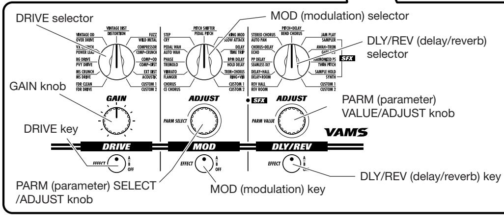
Naming of Parts
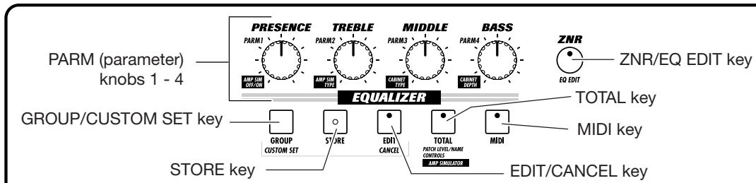
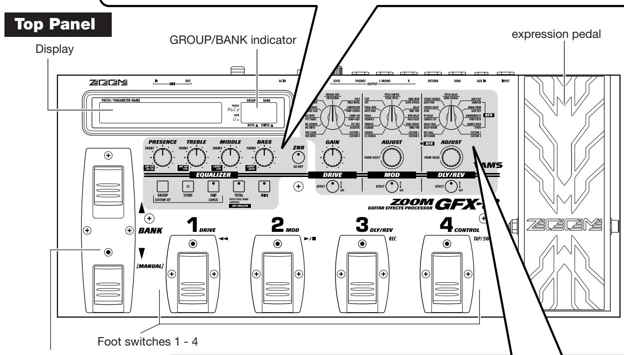
BANK UP/DOWN [MANUAL] foot switches
Rear Panel
EXTERNAL DIST
(distortion)SENDjack
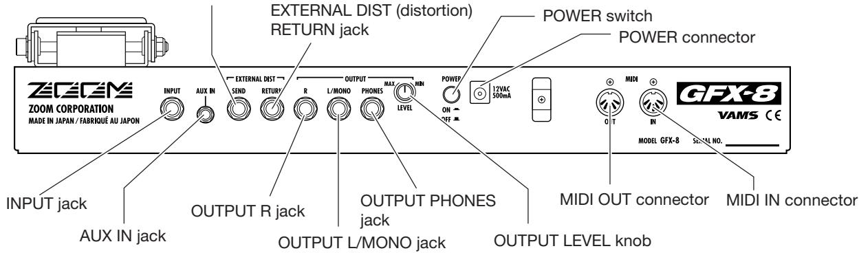
- The MIDI OUT connector can also be switched internally to serve as MIDI THRU connector (see page 35).
This section explains some important terms that are used throughout the GFX-8 documentation.
■ Effect module
An "effect module" in the GFX-8 works like a stand-alone compact effect device such as a distortion or delay. In the GFX-8, you can
use the four effect modules DRIVE, EQUALIZER, MOD, and DLY/REV as well as the ZNR (Zoom Noise Reduction) + AMP SIM (Amp Simulator) simultaneously.
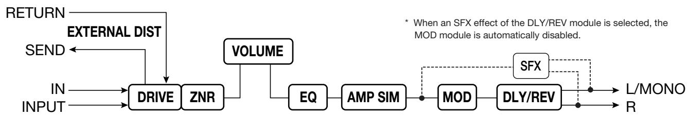
Signal flow in the GFX-8
Effects and parameters
An effect is a specific processing function in a module. The effect modules DRIVE, MOD, and DLY/REV each have 22 effects, from which one can be selected. The various settings of an effect that can be freely modified by the user are called parameters. The GFX-8 uses two kinds of parameters: effect parameters which are stored separately for each patch and global parameters which apply to all patches.
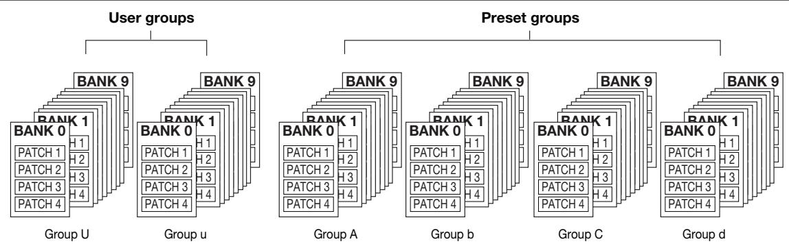
Patch/group/bank
Effect module combinations and effect parameter settings are stored in memory as "patches". The GFX-8 can store a total of 240 patches. These are divided into 80 read/write patches in the user groups (U and u) and 160 read-only patches in the preset groups (A, b, C, d). Each group has 10 banks numbered from 0 - 9, and each bank has 4 patches which can be selected with the foot switches 1 - 4 on the top panel of the unit.
■ Modes
The GFX-8 has five different operation modes, as listed below.
- Play mode
In this mode, patches can be selected and played. This is the default mode of the GFX-8 that is always active when power is turned on.
- Manual mode
In this mode, you play your instrument while manually switching modules on and off.
- Edit mode
In this mode, the effect parameters of the currently selected patch can be edited (changed).
- Jam play mode
In this mode, you can record a guitar phrase and play it back in normal, reverse, or scratch style.
- Sampler mode
In this mode, you can use the sampler function to record and play back a phrase from guitar or a source such as a CD player.
RTM (real-time modulation)
This refers to changing effect parameters in real time. For example, you can use the expression pedal to change the mix ratio of the reverb sound, or adjust the delay time during a song using a MIDI sequencer.
The type and range of the parameter to be changed, as well as the controller type (expression pedal or MIDI control change information) can be stored separately for each patch.
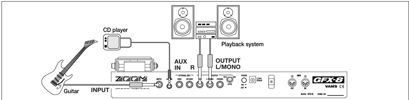
Connection Example (1) Instrument/amplifier connection
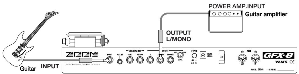
Connection Example (2) Connection to power amp input jack of guitar amplifier
If your guitar amplifier is equipped with a power amplifier input jack, you can directly connect the OUTPUT L/MONO jack of the GFX-8 to the power amp input jack, using the GFX-8 as a guitar preamplifier.
- When using the GFX-8 in this way, it is recommended to activate the built-in amp simulator (see page 7).
Connection Example (3) CD player/MD player connection
A component with stereo line level output such as a CD player or MD player can be connected to the AUX IN jack, using a stereo Y cable. The signal supplied to this jack is not processed by the effects of the GFX-8 and is sent directly to the OUTPUT jacks. This allows you for example to listen to a CD while practicing a guitar phrase.
- Using the sampler function of the GFX-8, it is also possible to record the signal supplied to the AUX IN jack (see page 34).
- When using hi-fi equipment (mixer, audio system or similar) instead of a guitar amplifier, activating the built-in amp simulator (see page 7) is recommended.
This section explains the steps you should take before playing sound through the GFX-8.
Power Up
- Verify that the AC adapter, instrument, and amplifier/playback system are correctly connected to the GFX-8.
Before making any connections, be sure to turn power to all components off. Also, you should turn the volume on the amplifier or playback system to minimum, and set the
OUTPUT LEVEL knob on the rear panel of the GFX-8 to the 12 o'clock position.
- Turn the system on in the order GFX-8 amplifier.
- While playing your instrument, adjust the volume control on the amplifier, the level control of the instrument, and the OUTPUT LEVEL knob of the GFX-8 to a suitable position.
Setting up the Amp Simulator
The GFX-8 incorporates an amp simulator that can duplicate the electrical characteristics and cabinet sound of various guitar amplifiers. Before starting to use the GFX- 8, we recommend that you set up the amp simulator so that it matches the connection type of the playback system or guitar amplifier. This will assure that you get optimum results from the GFX-8.
- Immediately after turning on the GFX-8, press the TOTAL key.
The GFX-8 switches to the edit mode which allows you to change various internal settings. The TOTAL key flashes red, and the display shows "PATCHLVL".

- Press the TOTAL key twice, so that it flashes orange.
The display indication changes to "AMP SIM".

- Use the PARM knobs 1 - 4 to select the amp simulator setting that matches the playback system.
While the TOTAL key is flashing orange, the PARM knobs 1 - 4 serve to set the amp simulator operation.
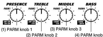
(1) PARM knob 1 AMP SIM
Switches amp simulator ON/OFF.
(2) PARM knob 2 AMP TYPE
Selects the amp simulator characteristics as follows (only if parameter 1 is set to "on".
Line connection
- LC General combo type amplifier
-Lb Bright combo type amplifier
-LS Stack type amplifier
Power amplifier connection
-AC Combo type amplifier
-AS Stack type amplifier
(3) PARM knob 3 CABINET
Selects the speaker cabinet simulator type.
-oF Cabinet simulator OFF
C1 Combo amplifier cabinet with one 12" speaker
C2 Combo amplifier cabinet with two 12" speakers
- ST Stack amplifier with four 10" speakers
- WL Stack amplifier tower with four 10^ speakers
(4) PARM knob 4 CABI DPT
Adjusts the depth of the cabinet simulator effect, in the range from 0 - 10.
Recommended settings for various connection methods and playback systems are as follows.
Connected to guitar amplifier input jack
| PARM 1 | PARM 2 | PARM 3 | PARM 4 |
| oF | -- | -- | -- |
Connected to power amplifier input jack of guitar amplifier
| PARM 1 | PARM 2 | PARM 3 | PARM 4 |
| on | AC AS | oF | -- |
- Connected to hi-fi playback system such as mixer or audio system
| PARM 1 | PARM 2 | PARM 3 | PARM 4 |
| on | LC | C1 | 0 - 10 |
| Lb | C2 | ||
| ST | |||
| LS | WT |
- When the settings are complete, press the STORE key twice.

The new amp simulator setting is stored. This setting is retained also when power to the unit is turned off.
Quick Guide (Trying Out the Unit)
The Quick Guide explains the basic steps for using the GFX-8 in play mode. This lets you use the unit right away, to check out what it can do.

Selecting the patch/bank number/group
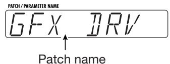
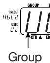
In play mode, the name of the currently selected patch is shown on the display. The group and bank number of the patch can be checked on the GROUP/BANK indicator.
① To switch the patch within the same bank, press one of the foot switches 1 - 4
whose LED is not lit.
* If you press the foot switch whose LED is lit, the GFX- 8 goes into the bypass condition.
② To switch to a patch from another bank number or group, use the BANK UP/DOWN foot switches and the foot switches 1 - 4 to select the bank number and group.
- For details on patch/bank/group switching, refer to p. 10.

To alter the effect with RTM
RTM (real-time modulation) refers to changing an effect with the expression pedal in real time.
(1) Rock the expression pedal back and forth.
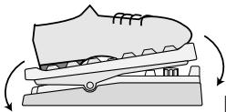
Move back and forth
The effect changes as the expression pedal is moved. The parameter that is controlled can be programmed for each patch. Try out this function to see which parameter changes for the stored patches.
② Push the expression pedal fully down.
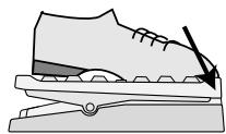
Push fully down
The expression pedal incorporates a switch that operates when the pedal is pushed firmly down. The switch turns the module for which RTM control is possible on and off.
- For information on effects that allow RTM control, see p. 30.
- For more information on the use of the expression pedal, see p. 41.

To select other effects or adjust the effect intensity, use the easy edit function.
The steps listed below will result in a change of the patch sound quality and effect intensity.
① To adjust the patch sound quality, operate PARM knobs 1 - 4.
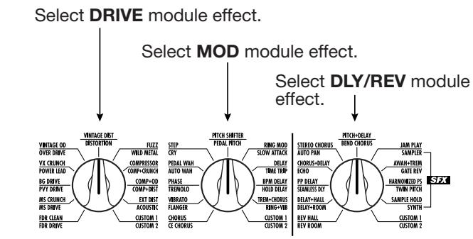
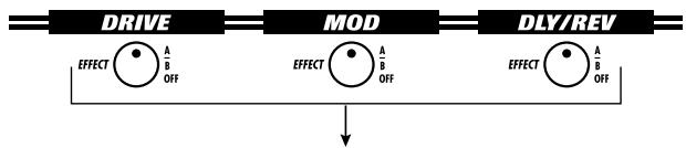
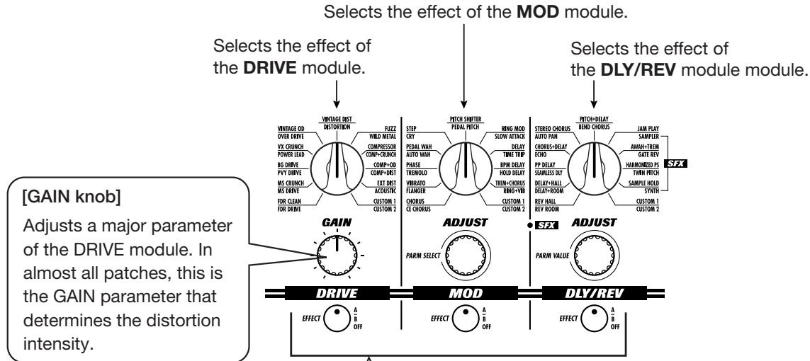
② To change the effect, use the DRIVE, MOD, DLY/REV selectors and keys.
Turn the selector to choose the desired effect in the respective module (DRIVE, MOD, DLY/REV).
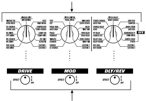
Switches the respective module (DRIVE, MOD, DLY/REV) ON and OFF and switches the group for selectable effects.
③ To change the effect intensity, operate the GAIN, PARM SELECT, or PARM VALUE knob.
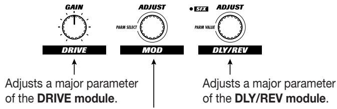
Adjusts a major parameter of the MOD module.
- During adjustment, the key for that module flashes.
- The parameter that can be adjusted differs for each patch.
- For more information on easy edit, see p. 11.
- For more information on full edit, see p. 14.

To store an adjusted patch
To store an edited patch, press the STORE key twice.
If required, change the store target with the BANK UP/DOWN foot switches and foot switches 1 - 4 before pressing the STORE key twice. Note that only patches in a user group can be selected as store targets.
If you press the CANCEL key before pressing the STORE key twice, the store procedure is aborted and the unit returns to the play mode.
- For more information on storing patches, see p. 18.

Other useful functions
- For information on using the amp simulator, see p. 7.
- For information on using the built-in tuner, see p. 12.
- For information on record/playback of phrases (sampler), see p. 34.
- For information on special playback of recorded phrases (jam play), see p. 32.
Listening to Patches (Play Mode Operation)
Selecting and playing patches stored in the memory of the GFX-8 is called "play mode". The GFX-8 is always in this mode immediately after being turned on. This section describes how to use the functions available in this mode.
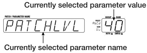
Panel Indication in Play Mode
In play mode, the following information is shown on the panel.
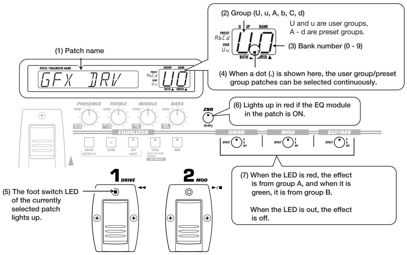
Selecting a Patch
- To switch patches in play mode, press a foot switch 1 - 4 whose LED is not lit.
In play mode, foot switches 1 - 4 serve to select a patch from the same group/bank. The LED of the currently selected foot switch is lit.
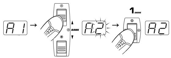
2 To select a patch from a different group/bank, press the BANK UP or DOWN foot switch to switch the group/patch, and then use the foot switches 1 - 4 to select the new patch.
For example, when the BANK UP foot switch is pressed repeatedly, the group/bank number changes as follows.
User group
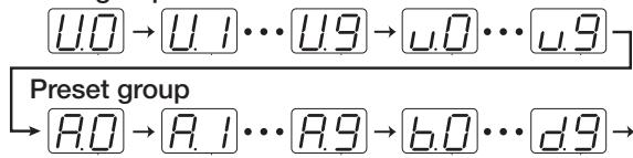
The patch is not switched as long as you only switch the bank/group (changed section of GROUP/BANK indicator
flashes). It is switched only after you press one of the foot switches 1 - 4 (the flashing of the GROUP/BANK indicator stops).

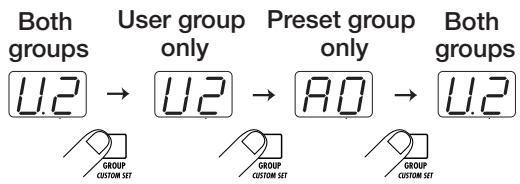
If desired, you can limit the action of the BANK UP/DOWN foot switches to select only user group banks, or only preset group banks. To do this, press the GROUP key. With each push of this key, the selectable groups are cycled as follows.
Using the Easy Edit Function
To edit patches of the GFX-8, the user normally will activate the edit mode, select the desired parameter, and change the setting. However, it is also possible to switch effects in modules and change major effect parameters in play mode. This is called the easy edit function.
- To switch the effect used in the DRIVE, MOD, or DLY/REV module, operate the selector and key for the respective module.
Switches the respective module (DRIVE, MOD, DLY/REV) ON and OFF and switches the group for selectable effects. With each push of the key, the unit cycles through the following three states.
Key out or slowly flashing red
Respective module is OFF.
Key lit/flashing red Module is ON and effect from group A (upper labels) is selected.
Key lit/flashing green Module is ON and effect from group B (lower labels) is selected.
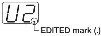
When the effect is switched, the name of the new effect is shown on the display for about 2 seconds. The EDITED mark (. in the GROUP/BANK indicator lights up. This indicates that an effect parameter of this patch has been edited. The mark disappears when the setting is changed back to the original setting.

While only the effect group was switched, the previous effect is still active. The change does not occur until the selector for the respective module is operated. Therefore the selector position and the actual effect may differ during this interval.
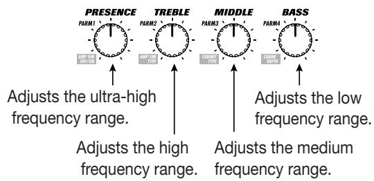
- To adjust a major parameter of each module, operate the following knobs.
[EQ] PRESENCE:
Adjusts boost/cut in the ultra-high frequency range.
![ZOOM GFX-8 - [EQ] PRESENCE: - 1](/content/2025/01/152217/images/1b90ad29eb732b48881972777a0e73ef4515b0e37a5b139c8f49b5ea870c34ac.jpg)
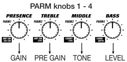
[PARM knobs 1 - 4]
Adjust the following EQ module parameters.
[GAIN knob]
Adjusts a major parameter of the DRIVE module. In almost all patches, this is the GAIN parameter that determines the distortion intensity.
![ZOOM GFX-8 - [GAIN knob] - 1](/content/2025/01/152217/images/d8fa51f877638d6fb9b28cccb8af3f4dc64a439d8d259cb37b859aeccb1105ef.jpg)
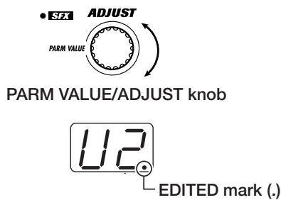
[PARM VALUE/ADJUST knob]
Adjusts a major parameter of the DLY/REV module.
When one of the above knobs is moved, the display shows the parameter name and the GROUP/BANK indicator shows the parameter value for about 2 seconds.
![ZOOM GFX-8 - [PARM VALUE/ADJUST knob] - 1](/content/2025/01/152217/images/9637f62e5ca3f269e9ff7b96b88dc2a51d9ca7c796f445fdb874bbe5bebcad98.jpg)
Which parameter is assigned to the GAIN knob, PARM SELECT/ADJUST knob, and PARM VALUE/ADJUST knob depends on which effect is selected for that module (see page 19 - 29).
![ZOOM GFX-8 - [PARM VALUE/ADJUST knob] - 2](/content/2025/01/152217/images/888244a7d66b06ef8a2f000ee995529a52b51cd2e722f2cce3ba9759dc2cd37d.jpg)
- Trying to change effects or parameters which are set to OFF in the current module has no effect. In this case, the indication "OFF" is shown on the display.
- All changes made with the easy edit function are temporary. Settings revert to the original condition when the patch is switched. When wishing to keep the changes, you must store the patch (see page 18).
Using the Bypass (Mute)/Tuner Function
The GFX-8 incorporates an auto-chromatic tuner for guitars. To use the tuner function, the built-in effects must be bypassed (temporarily turned off) or muted (original sound and effect sound turned off).
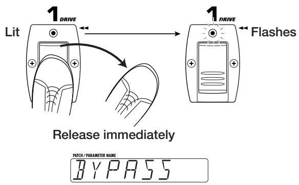
- To set the GFX-8 to the bypass (mute) condition, press and immediately release the foot switch 1 - 4 that has selected the currently active patch (the foot switch whose LED is lit).
In play mode, when you quickly press the foot switch whose LED is lit, the GFX-8 switches to the bypass condition. The foot switch LED now flashes and the indication "BYPASS" is shown on the display.
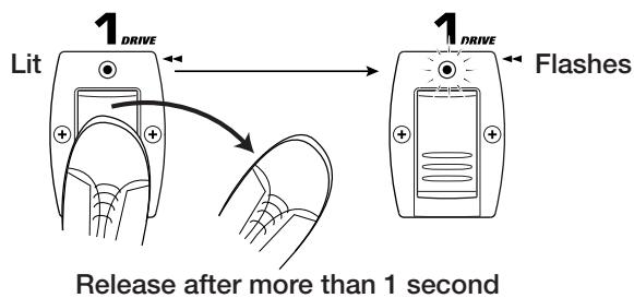
If you press a foot switch with lit LED for longer than 1 second and then release it, the GFX-8 switches to the mute condition. The foot switch LED now flashes and the indication "MUTE" is shown on the display.

- Play the open string you want to tune, and watch the GROUP/BANK indicator. The GFX-8 automatically detects the pitch and the GROUP/BANK indicator shows the note which is closest to the current pitch.
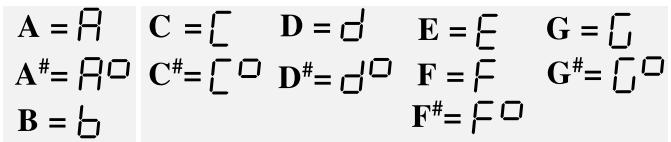

For tuning, always play a single note. If you play a chord, the pitch will not be detected correctly.
- When the GROUP/BANK indicator shows the desired note, perform fine tuning while watching the display.
- Tune the other strings in the same way.
- When tuning is completed, press the foot switch whose LED is flashing once more.
The GFX-8 returns to the play mode.

If desired, you can change the setting of the unit so that pressing the foot switch whose LED is lit will not activate the bypass/mute condition. For details, please refer to page 41.
Adjusting the Reference Pitch of the Tuner
After the GFX-8 is turned on, the tuner reference pitch is always "center A = 440 Hz". If desired, you can change the reference pitch. This is useful for example to match your instrument to another instrument or sound source whose pitch cannot be changed easily, such as an acoustic piano or a CD. To do this, first change the reference pitch of the GFX-8 and then use to to perform tuning of your guitar.
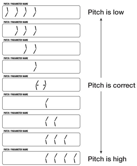
- In play mode, press the foot switch 1 - 4 whose LED is lit, to set the GFX-8 to the bypass/mute condition.
- Rotate the DLY/REV (PARM VALUE) knob to adjust the reference pitch. When this knob is operated, the current reference pitch is shown on the display. The initial setting is "440" (center A = 440 Hz).
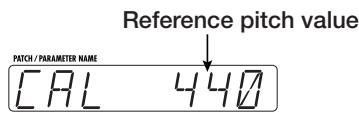
The available setting range is "435" (center A = 435Hz ) - "445" (center A = 445Hz ) in 1-Hz steps.
3. When tuning is completed, once more press the foot switch whose LED is flashing.
The GFX-8 returns to the play mode.

When the GFX-8 is turned off and on again, the reference pitch will be reset to "440".
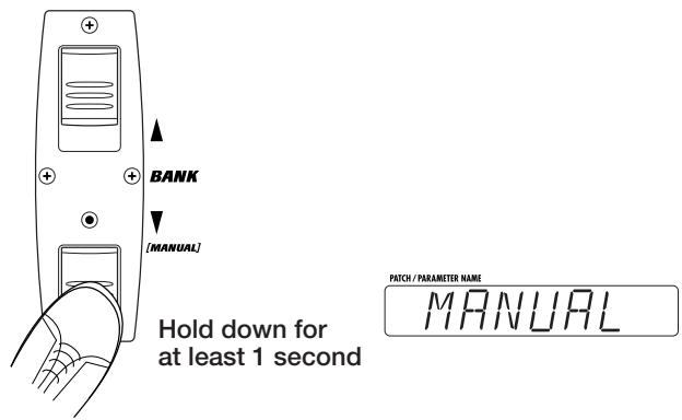
Switching Modules On and Off During Play (Manual Mode)
The condition where foot switches 1 - 4 can be used to switch the modules in a patch ON and OFF individually and where specific parameters can be adjusted is called "manual mode". In manual mode, the modules in a patch can be used like independent compact effects.
- In play mode, select a patch.
- Press the BANK DOWN foot switch and hold it down for at least 1 second.
The GFX-8 switches to the manual mode. The display shows "MANUAL".
- Operatefoot switches1-4.
In manual mode, foot switches 1 - 4 have the following functions.
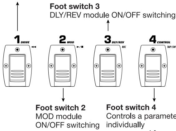
Foot switch 1
DRIVE module ON/OFF switching
Foot switch 4
Controls a parameter individually programmed for each patch, such as module bypass, delay time tap input, etc.

The parameter to be controlled by foot switch 4
(CONTROL switch) is set using the TOTAL module (see page 29).
- To return to the play mode, press the BANK DOWN foot switch once more.
Changing the Sound of a Patch (Edit Mode)
The condition where you can change the parameters that make up a patch to create your own sound is called "edit mode". This section describes how to use edit mode.
Basic Edit Mode Steps
The basic steps that are normally taken in edit mode are explained here. Besides these, the edit mode also provides a short cut to quickly edit a specific parameter (see page 16).
- In play mode, select the patch you want to edit.
The patch can be from a user group or preset group. However, because patches in the preset groups are read-only, after you have edited a patch, you can only select a user group patch as store target.
- Press the EDIT key.
The EDIT key LED lights up, and the GFX-8 enters the edit mode.

In edit mode, the following information is shown on the panel.
The keys and foot switch LEDs of modules that are ON in the current patch are lit.
The key of the module selected for editing flashes.

When edit mode was activated immediately after switching patches, the TOTAL key flashes. When edit mode was activated after easy edit, the key of the edited module flashes.
- Use the panel keys to select the module you want to edit.
In edit mode, the following keys serve to select the module for editing. The selected key flashes.
ZNR/EQ EDIT key
Selects the EQ module or ZNR.
With each push of the key, the color of the flashing LED changes, and the edit target changes as follows.
Flashing red
EQ module page 1
Flashing green
EQ module page 2
Flashing orange
ZNR
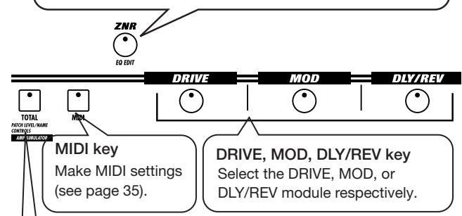
TOTAL key
Serves to set the patch name and patch level (overall output level of the patch) and other parameters applying to the entire patch, as well as global parameters that apply to all patches. With each push of the key, the color of the flashing LED changes, and the edit target changes as follows.
Flashing red
Flashing green
Flashing orange
Set patch name and patch level.
Set RTM and CONTROL switch functions (see page 30).
Make amp simulator (global parameter) settings.

If a module is selected that is set to OFF in the current patch, editing is not possible (display shows "OFF").
However, ZNR settings can be made also when the EQ module is OFF.
- Use the PARM SELECT knob to select the parameter you want to edit.
When you turn the PARM SELECT knob, the effects of the module selected in step 3 and the effect parameters are shown in turn on the display. (Which parameter is shown depends on the currently selected module and effect). The currently selected parameter setting can be checked using the GROUP/BANK indicator.
5. Use the PARM VALUE/ADJUST knob to change the parameter setting (or the effect).
To change the parameter shown on the display, use the PARM VALUE/ADJUST knob. When a change is made to any effect selection or parameter, the EDITED mark (. ) appears on the GROUP/BANK indicator.
6. To change the effect module ON/OFF setting, use the following foot switches or keys.
In edit mode, the following keys or foot switches can be used to change the module ON/OFF setting. The key of a module that has been set to OFF goes out, and the module cannot be edited any more. (However, the ZNR settings can be changed also if the EQ module is OFF.)
- DRIVE module
DRIVE key (*1), Foot switch 1
- MOD module
MOD key (*1), Foot switch 2
- DLY/REV
DLY/REV key (*1), Foot switch 3
- EQ module.
ZNR/EQ EDIT key (*2)
(^1) Each push of the key: group A, group B, OFF
(^2) Each push of the key: ZNR (orange) EQ page 1 (red) EQ page 2 (green). When EQ page 1 or 2 is selected, keeping the key depressed for 1 second switches EQ ON or OFF.
- When wishing to continue editing other parameters or modules, repeat steps 3 - 6.
8. When editing is complete, press the EDIT/CANCEL key.
The GFX-8 returns to the play mode.

All changes made in edit mode are temporary. Settings revert to the original condition when the patch is switched. When wishing to keep the changes, you must store the patch (see page 18).
In edit mode, the following knobs and keys can be used to directly edit the effect selection or parameter.
[DRIVE/MOD/DLY/REV selector]
[DRIVE/MOD/DLY/REV key]
Switches the respective module (DRIVE, MOD, DLY/REV) ON and OFF and switches the group for selectable effects. With each push of the key, the unit cycles through the following three states.
Key out or slowly flashing red
Respective module is OFF.
Key lit/flashing red
Module is ON and effect from group A (upper labels) is selected.
Key lit/flashing green
Module is ON and effect from group B (lower labels) is selected.
When the effect is switched, the name of the new effect is shown on the display for about 2 seconds.
Edit Mode Shortcut (2)
Using PARM knobs 1 - 4, the main parameters of each module can be quickly edited.
- Use the DRIVE, MOD, DLY/REV, ZNR/EQ EDIT, or TOTAL key to select the module you want to edit.
The selected key starts to flash.
- Use the PARM knobs 1 - 4 to edit the parameter selected in step 1.
In edit mode, the main parameters (parameter 1 - 4) of the currently selected module are assigned to PARM knobs 1 - 4.
For example, when the effect OVER DRV of the DRIVE module is selected, the PARM knobs 1 - 4 control the following parameters.
Creating Custom Distortion
The effect numbers 11A and 11B of the DRIVE module are reserved for custom distortion effects created by the user. For custom distortion, in addition to the regular effect parameters (PARM1 - PARM8), there are four more parameters (PARM9 - PARM12) which allow control over the distortion character and other characteristics.
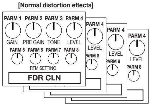

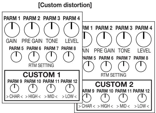
PARM 9 >CHAR < Distortion character
PARM 10 > HIGH < High-range character
PARM 11 > MID < Mid-range character
PARM 12 > LOW < Low-range character
Once you have set these parameters and stored the result as a patch, you can use it as a new distortion effect in other patches.
- Activate edit mode.
- Select CUSTOM1 (11A) or CUSTOM2 (11B) of the DRIVE module.
Verify that the DRIVE module is ON.
- Call up parameters 1 - 8 and make the desired settings.

To make optimum use of custom distortion parameters, we recommend to set parameters 1 - 4 as follows.
PARM1 GAIN 1-30(as desired)
PARM2 PRE GAIN 7
PARM3 TONE 5
PARM4 LEVEL 25
- Press the GROUP/CUSTOM SET key once.
This calls up parameter 9. The name of the parameter (">CHAR<") appears on the display, and the GROUP/BANK indicator shows the current value.
Parameter 9 can also be called up with the PARM SELECT knob. This is convenient to switch between any parameter from 1 - 12.
- Use the PARM VALUE knob to adjust the value.
Parameters 9 - 12 are special parameters for custom distortion, allowing setting characteristics separately for each frequency band. - Call up parameters 10 - 12 in the same way with the PARM SELECT knob, and use the PARM VALUE knob to adjust the value.
- When you have created a custom distortion effect, store the patch.

That parameters 9 - 12 are global parameters that affect all patches. For example, when parameters 9 - 12 of custom distortion 1 in a patch were adjusted, and the patch was stored, the changes will affect all patches using custom distortion 1 (effect type 11A).
Storing Custom Module Settings
The settings for the MOD module and DLY/REV module can be stored as custom settings. Stored custom settings can be called up at any time in edit mode, for use with new patches or existing patches.

The operation steps are different than for creating custom distortion in the DRIVE module.
- Activate edit mode.
- Press the MOD key or DLY/REV key to select the module for which you want to store custom settings.
Verify that the selected module is ON.
- Make the desired effect selection and parameter settings for the module selected in step 2.
- Press the GROUP/CUSTOM SET key.

The effect name flashes on the display, and the indication "C1" flashes on the GROUP/BANK indicator.

When the respective module is OFF, custom module settings cannot be stored.
- Press the GROUP/CUSTOM SET key and select C1 (custom setting 1) or C2 (custom setting 2).
- To store the custom settings you have made, press the STORE key.

The stored custom settings can be selected at any time, simply by choosing 11A (custom setting 1) or 11B (custom setting 2) for the MOD module or DLY/REV module.
To cancel the store process, press the CANCEL key.
Storing and Copying Patches (Store Mode Operation)
Unless you store edited patches in memory, the settings will revert to the original condition when the patch is switched. Do not forget to store any edited patches that you wish to keep.
It is also possible to copy an existing patch and store it at another location. For example, copying all patches to be used in a specific song to one user group bank will make it easy to call up the patches with foot switches 1 - 4 during a performance.
- In play mode or edit mode, press the STORE key.

The GFX-8 goes into store standby mode and the indication "STORE?" and the store target patch name are shown alternately on the display. The GROUP/BANK indicator shows the store target group/bank number. The LED of one of the foot switches 1 - 4 corresponding to the store target lights up.
If you wish to store the edited patch in another location than the currently shown store target, change the patch name before pressing the STORE key.

- Use the BANK UP/DOWN foot switches and foot switches 1 - 4 to select the store (copy) target.
When the edited patch was from a user group, the original group/bank/foot switch will be selected as store target if no
other steps are taken. When the group/bank is changed, the changed part of the GROUP/BANK indicator flashes.
- To execute the patch store (copy) process, press the STORE key once more.
The store (copy) process is carried out, and the unit automatically reverts to the play mode.
To cancel the operation, press the CANCEL key before pressing the STORE key the second time.
- The patches in the preset groups (A, b, C, d) are read-only and cannot be used as store targets. When the STORE key is pressed while a patch from a preset group is selected, the store target is automatically changed to "U0" and foot switch 1. If required, change the store target with the USER group/bank/foot switch.
- When the store (copy) process is executed, the previous contents of the store (copy) target are overwritten and cannot be restored. However, the factory default settings of any user group patch (or all patches) can be restored (see page 41).
Effects and Parameters
This section lists all the effects and parameters available in the modules of the GFX-8. Parameters which are common for several or all effects are explained only once.
DRIVE Module
This module comprises a wide variety of effects, including clean acoustic simulator, distortion, overdrive, and fuzz.

[GLOBAL] indicates a global parameter that applies to all patches.

[CONTROL SW] indicates an item that can be operated with the CONTROL switch (see page 31).
- Parameter 1 of the DRIVE module can be adjusted with the GAIN knob also when another module is selected.
* TYPE 1A - 7B have the same parameters.
TYPE
1A
FDR CLN
Clean sound of built-in type tube amp.
TYPE
1B
FDR DRV
Drive sound of built-in type tube amp.
TYPE
2A
MS CRU
Crunch sound of British style tube stack amp.
TYPE
2B
MS DRV
Drive sound of British style tube stack amp.
TYPE
3A
BG DRV
Drive sound of tube stack amp with fat midrange.
TYPE
3B
PVY DRV
Drive sound of high-gain tube stack amp, ideal for heavy metal.
TYPE
4A
VX CRU
Old-style crunch sound.
TYPE
4B
PWR LEAD
Lead guitar sound with good power balance.
TYPE
5A
V-OD
Dry overdrive sound.
TYPE
5B
OVER DRV
Cabinet ringing style overdrive sound.
TYPE
6A
V-DIST
Distortion sound with dry character.
TYPE
6B
DIST
Strong distortion sound.
TYPE
7A
FUZZ
Boomy fuzz tone.
TYPE
7B
WD METAL
High-gain aggressive sound.
GAIN knob
GAIN
1-30
Parameter 1
GAIN
1-30
Adjusts the final gain.
Parameter 2
PRE GAIN 1-10
Adjusts the basic distortion amount.
Parameter 3
TONE 0-10
Adjusts the tone.
Parameter 4
LEVEL
1-30
Adjusts the level of the signal after passing the DRIVE module.
Parameter 5
RTM MAX
0-99,1.0
Using the maximum value of the parameter adjusted by RTM as reference (100%) , this parameter adjusts the RTM maximum value in the range from 0% (0) - 100% (1.0).
Parameter 6
RTM MIN
0-99,1.0
Using the maximum value of the parameter adjusted by RTM as reference (100%) , this parameter adjusts the RTM minimum value in the range from 0% (0) - 100% (1.0).
Parameter 7
RTM DES
1-4
Selects the parameter to be adjusted by RTM. Parameter 1 - 4 can be selected.
Parameter 8
RTMCTL
oF,Pd,1-5,8-31
Selects the controller to use for RTM. Available settings are "oF" (off), "Pd" (expression pedal), MIDI control change 1 - 5, 8 - 31.

When the DRIVE module is ON, the switch functions as a boost switch that further raises the level of the DRIVE module. With each push of the CONTROL switch (foot switch 4), the setting is toggled between normal (LED out) and boost (LED lit).
TYPE
8A
COMP
This is a combination of compressor and clean sound.
GAIN knob
COMP SNS
oF, -10
Parameter 1
TONE
0-10
Parameter 2
COMP SNS
oF,1-10
Adjusts the compressor effect depth. When set to "oF", the effect does not operate.
Parameter 3
ATTACK
1-10
Adjusts the rise time of the effect.
Parameter 4
Para
heter 8
See TYPE 1A (FDR CLN).

See TYPE 1A (FDR CLN).
- TYPE 8B - 9B have the same parameters.
TYPE
8B
CMP+CRU
This is a combination of compressor and crunch.
TYPE
9A
CMP+OD
This is a combination of compressor overdrive.
TYPE
9B
CMP+DIST
This is a combination of compressor and distortion.
GAIN knob
GAIN 1-30
Parameter 1
GAIN 1-30
Adjusts the effect intensity.
Parameter 2
COMP SNS
oF,1-10
Adjusts the compressor effect depth. When set to "oF", the effect does not operate.
Parameter 3 ATTACK 1-10
Adjusts the rise time of the effect.
Parameter 4 - Parameter 8
See TYPE 1A (FDR CLN).

See TYPE 1A (FDR CLN).
TYPE 10A EXT DIST
Instead of the internal DRIVE module, a distortion effect connected to the rear-panel EXT.DIST SEND/RETURN jacks is used.
GAIN knob SEND LVL 1-10
Parameter 1 SEND LVL 1-10
Adjusts the signal level supplied at the EXT.DIST SEND jack.
Parameter 2 COMP SNS oF,1-10
Adjusts the compressor effect depth. When set to "oF", the effect does not operate.
Parameter 3 ATTACK 1-10
Adjusts the rise time of the effect.
Parameter 4 - Parameter 8
See TYPE 1A (FDR CLN).

See TYPE 1A (FDR CLN).
TYPE 10B ACOUSTIC
Changes the sound of an electric guitar into an acoustic guitar sound.
GAIN knob TOP 1-10
Parameter 1 TOP 1-10
Adjusts the special string character of the acoustic guitar.
Parameter 2 BODY 1-10
Adjusts the body character of the guitar.
Parameter 3 TONE 0-10
Adjusts the overall sound quality.
Parameter 4 - Parameter 8
See TYPE 1A (FDR CLN).

See TYPE 1A (FDR CLN).
TYPE 11A CUSTOM1
TYPE 11B CUSTOM2
These effects let you design your very own distortion circuit to achieve any desired sound.
GAIN knob GAIN 1-30
Parameter 1 GAIN 1-30
Adjusts the overall gain.
Parameter 2 PRE GAIN 1-10
Adjusts the basic distortion.
Parameter 3 TONE 0-10
Adjusts the tone.
Parameter 4 - Parameter 8
See TYPE 1A (FDR CLN).
Note that parameters 9 - 12 below are global parameters that apply to all patches. (For details, see page 17.)
The custom distortion effects can be customized in further detail using the supplied software.
Parameter 9 >CHAR<
Selects the distortion character in the high-frequency range.
c1, c2: Clean type distortion
o1, o2: Overdrive type distortion
d1, d2: Regular distortion
A1, A2: Amp distortion
S1, S2: Sound set with editing software on computer
Parameter 10 > HIGH<
Selects the distortion character in the low- frequency range.
L1-L4:Low-pass
Ft: Flat
P1 - P4: Peaking
S1, S2: Sound set with editing software on computer
Parameter 11 > MID<
Selects the distortion character in the mid- frequency range.
L1 - L3: Low-range emphasis
M1 - M3: Mid-range emphasis
H1 - H3: High-range emphasis
S1, S2: Sound set with editing software on computer
Parameter 12 > LOW<
Selects the distortion character in the low-frequency range.
H1 - H2: High-pass
Ft: Flat
P1 - P4: Peaking
b1, b2: Boost
S1, S2: Sound set with editing software on computer
See TYPE 1A (FDR CLN).
ZNR/EQ (Zoom Noise Reduction/Equalizer) Module
This module contains the ZNR (Zoom Noise Reduction) function that reduces noise during pauses, and an equalizer for adjusting the spectral balance of the sound.
[CONTROL SW] indicates an item that can be operated with the CONTROL switch (see page 31).
-
In edit mode, the color of the flashing ZNR/EQ EDIT LED changes with each push of the key, and the editing target is switched as follows.
-
Flashing orange ZNR
- Flashing red EQ module page 1
- Flashing green EQ module page 2
ZNR (Zoom Noise Reduction)
This circuit achieves noise reduction during play pauses without affecting the character of the sound.
Parameter 1 ZNR oF, 1-15
Adjusts the ZNR sensitivity. Select the setting that yields best noise reduction without causing the sound to become unnatural. When set to "oF", the ZNR action is defeated.
EQ P1 (Equalizer Page 1)
This is page 1 of the four-band equalizer that serves to tailor the sound. There is only one equalizer effect, but because it has many parameters, the settings are divided into two pages (EQ P1/EQ P2) for operation
with the ZNR/EQ EDIT key. (If the PARM SELECT knob is used, parameters 1 - 12 can be called up continuously.)
Parameter 1 PRESENCE -12-12
Adjusts boost/cut in the ultra-high range (above 8kHz
Parameter 2 TREBLE -12-12
Adjusts boost/cut in the high range.
Parameter 3 MIDDLE -12-12
Adjusts boost/cut in the midrange.
Parameter 4 BASS -12-12
Adjusts boost/cut in the low range.
EQ P2 (Equalizer Page 2)
This is page 2 of the four-band equalizer.
Parameter 1 EQ LEVEL 1-30
Adjusts the level of the signal after passing the EQ module. A setting of 25 gives unity level (input level = output level).
Parameter 2 TRBL FRQ 63-6.3 (see table)
Adjusts the center frequency in the high range (630 Hz - 6.3 kHz).
Parameter 3 MID FRQ 16-1.6 (see table)
Adjusts the center frequency in the midrange (160 Hz - 1.6 kHz).
Parameter 4 BASS FRQ 06-63 (see table)
Adjusts the center frequency in the low range (60Hz - 630Hz)
EQ module setting values and frequencies
| TREBLE FRQ | Display | MID FRQ | Display | BASS FRQ | Display |
| 630Hz | 63 | 160Hz | 16 | 60Hz | 06 |
| 800Hz | 80 | 200Hz | 20 | 80Hz | 08 |
| 1.2kHz | 1.2 | 315Hz | 31 | 125Hz | 12 |
| 1.6kHz | 1.6 | 400Hz | 40 | 160Hz | 16 |
| 2.5kHz | 2.5 | 630Hz | 63 | 200Hz | 20 |
| 3.2kHz | 3.2 | 800Hz | 80 | 315Hz | 31 |
| 5.1kHz | 5.1 | 1.2kHz | 1.2 | 400Hz | 40 |
| 6.3kHz | 6.3 | 1.6kHz | 1.6 | 630Hz | 63 |
Parameter 5 RTM MAX 0-99,1.0
Using the maximum value of the parameter adjusted by RTM as reference (100%) , this parameter adjusts the RTM maximum value in the range from 0% (0) - 100% (1.0).
Parameter 6 RTM MIN 0-99,1.0
Using the maximum value of the parameter adjusted by RTM as reference (100%) , this parameter adjusts the RTM minimum value in the range from 0% (0) - 100% (1.0).
Parameter 7 RTM DES 1-8
Selects the parameter to be adjusted by RTM. Parameter 1 - 8 can be selected.
Parameter 8 RTM CTL oF, Pd, 1 - 5, 8 - 31
Selects the controller to use for RTM. Available settings are "oF" (off), "Pd" (expression pedal), MIDI control change 1 - 5, 8 - 31.
When the effect is ON, the output is muted while the CONTROL switch is pressed (during muting, the LED lights up).
MOD (Modulation) Module
This module contains spatial effects such as chorus and flanger, unique sounding effects such as auto-wah, and modulation effects such as ring modulator.
Indicates a parameter that can be controlled by RTM (see page 30).
TAP Indicates a parameter for which tap input is possible with the CONTROL switch (see page 31).
1 Indicates a parameter that can be controlled with the PARM SELECT knob during easy edit (see page 11).
[CONTROL SW] indicates an item that can be operated with the CONTROL switch (see page 31).
Common Parameters of MOD Module
DEPTH
RATE
PRE DLY
xx MIX
BALANCE
Adjusts the effect depth.
Adjusts the modulation rate.
Adjusts the predelay time.
Adjusts the effect mix ratio.
Adjusts the balance between effect sound and original sound. Higher values result in more pronounced effect sound.
FEEDBACK
SHIFT
Adjusts the amount of feedback.
Adjusts the effect operation direction. "dn" means downward change, and "UP" upward change.
SENS
Adjusts the picking detection sensitivity for wah and the trigger sensitivity.
POSITION
Selects the MOD module connection point.
bF: Before DRIVE module AF: After EQ module
TYPE 1A CHORUS
This is a chorus effect with clear sound.
Parameter 1 DEPTH 0-50

Parameter 2 RATE 1-50
Parameter 3 PRE DLY 0-50
Parameter 4 CHO MIX 0-50
Parameter 5 RTM MAX 0-99,1.0
Using the maximum value of the parameter adjusted by RTM as reference (100%) , this parameter adjusts the RTM maximum value in the range from 0% (0) - 100% (1.0).
Parameter 6 RTM MIN 0-99,1.0
Using the maximum value of the parameter adjusted by RTM as reference (100%) , this parameter adjusts the RTM minimum value in the range from 0% (0) - 100% (1.0).
Parameter 7 RTM DES 1-4
Selects the parameter to be adjusted by RTM. Parameter 1 - 4 can be selected.
Parameter 8 RTM CTL oF, Pd, 1 - 5, 8 - 31
Selects the controller to use for RTM. Available settings are "oF" (off), "Pd" (expression pedal), MIDI control change 1 - 5, 8 - 31.
LED lit: CHO MIX parameter is at maximum.
LED out: CHO MIX parameter is at the value stored for that patch.
TYPE 1B CE CHO
This is a chorus effect characterized by warm sound.
Parameter 1 DEPTH 0-50
Parameter 2 RATE 1-50
Parameter 3 TONE 0-50

Adjusts the sound quality.
Parameter 4 CE MIX 0-50
Parameter 5 - Parameter 8
See TYPE 1A (CHORUS).
LED lit: CE MIX parameter is at maximum.
LED out: CE MIX parameter is at the value stored for that
DE 2A VIBRATO
This is a vibrato effect that periodically varies the pitch.
Parameter 1 DEPTH 0-50
Parameter 2 VIB RATE 1-50
Parameter 3 BALANCE 0-50
Parameter 4 RISETIME oF,1-50
Adjusts the delay between the input signal and the start of the effect. When the setting is "oF", the effect is always operating.
Parameter 5 - Parameter 8
See TYPE 1A (CHORUS).
LED lit: VIB RATE parameter is at maximum.
LED out: VIB RATE parameter is at the value stored for that patch.
TYPE 2B FLANGER
This effect produces a peculiar, undulating sound.
Parameter 1 DEPTH 0-50
Parameter 2 FLG RATE 1-50
Parameter 3 PRE DLY 0-50
Parameter 4 FEEDBACK -15-0-15
Adjusts the effect intensity.
Parameter 5 - Parameter 8
See TYPE 1A (CHORUS).
LED lit: FLG RATE parameter is at maximum.
LED out: FLG RATE parameter is at the value stored for that patch.
TYPE 3A PHASE
This effect produces a swooshing sound.
Parameter 1 RESO 1-50
Adjusts the resonance.
Parameter 2 PHA RATE 1-50
Parameter 3 CHAR 1-4
Selects the characteristics of the phase sound.
Parameter 4 POSITION bF, AF
Parameter 5 - Parameter 8
See TYPE 1A (CHORUS).
LED lit: PHA RATE parameter is at maximum.
LED out: PHA RATE parameter is at the value stored for
that patch.
TYPE 3B TREMOLO
This effect periodically varies the level of the sound.
Parameter 1 DEPTH 0-50
Parameter 2 TRM RATE 1-50
Parameter 3 CLIP 0-10
Adjusts the modulation signal waveform. Higher values result in stronger clipping of waveform tops.
Parameter 4 RISETIME oF,1-50

Adjusts the delay between the input signal and the start of the effect. When the setting is "oF", the effect is always operating.
Parameter 5 - Parameter 8
See TYPE 1A (CHORUS).
LED lit: TRM RATE parameter is at maximum.
LED out: TRM RATE parameter is at the value stored for that patch.
TYPE 4A PDL WAH (Pedal Wah)
This effect allows use of the expression pedal to manually adjust wah.
Parameter 1 PWA FREQ 1-50
Sets the center frequency of the wah effect.
Parameter 2 DRY LVL 0-50
Sets the level of the original sound.
Parameter 3 WET LVL 0-50
Sets the effect sound level.
Parameter 4 POSITION bF, AF
Parameter 5 - Parameter 8
See TYPE 1A (CHORUS).
If the effect is ON and the CONTROL switch is operated, the wah effect will be bypassed while the switch is being pushed.
TYPE 4B AUTO WAH
Operation of this effect varies according to the picking intensity.
Parameter 1 RESO 1-50
Adjusts the resonance.
Parameter 2 SHIFT dn, UP
Sets the wah effect direction.
Parameter 3 AWA SENS 1-50
Sets the effect sensitivity
Parameter 4 POSITION bF, AF
Parameter 5 - Parameter 8
See TYPE 1A (CHORUS).
If the effect is ON and the CONTROL switch is operated, the wah effect will be bypassed while the switch is pushed.
TYPE 5A STEP
This is a special effect with step-like filter characteristics.
Parameter 1 DEPTH 0-50
Parameter 2 STP RATE 1-50
Parameter 3 FEEDBACK 0-50
Parameter 5 - Parameter 8
See TYPE 1A (CHORUS).
LED lit: STP RATE parameter is at maximum. LED out: STP RATE parameter is at the value stored for that patch.
TYPE
5B CRY
This effect varies the sound like a talking modulator.
Parameter 1 DEPTH 0-50
Parameter 2 SHIFT dn, UP
Parameter 3 CRY SENS 1-50
Parameter 4 POSITION bF, AF
Parameter 5 - Parameter 8
See TYPE 1A (CHORUS).
If the effect is ON and the CONTROL switch is operated, the cry effect will be bypassed while the switch is pushed.
TYPE
6A PITCH
This is a pitch shifter with a range of 1 octave down and 2 octaves up.
Parameter 1 PITCH -12-0-12,24
Adjusts the pitch shift amount in semitones.
Parameter 2 FINE -10-10
Performs fine adjustment of pitch shift amount.
Parameter 3 TONE 0-50
Adjusts the tone of the effect.
Parameter 4 BALANCE 0-50
Adjusts the balance between effect sound and original sound.
Parameter 5 - Parameter 8
See TYPE 1A (CHORUS).
If the effect is ON and the CONTROL switch is operated, the effect will be bypassed while the switch is pushed.
TYPE
6B PDL PIT
(Pedal Pitch)
This effect allows manually changing the pitch, using the expression pedal.
Parameter 1 TYPE 1-16
Selects the pedal pitch type (see table below). Depending on the type, the pitch action is different when the pedal is raised and lowered.
| P-PIT TYPE | 1 | -100 cent | Original sound only |
| 2 | Original sound only | -100 cent | |
| 3 | DOUBLING | Detune + DRY | |
| 4 | Detune + DRY | DOUBLING | |
| 5 | 0 cent | +1 octave | |
| 6 | +1 octave | 0 cent | |
| 7 | 0 cent | -2 octaves | |
| 8 | -2 octaves | 0 cent | |
| 9 | -1 octave + DRY | +1 octave + DRY | |
| 10 | +1 octave + DRY | -1 octave + DRY | |
| 11 | -700 cent + DRY | 500 cent + DRY | |
| 12 | 500 cent + DRY | -700 cent + DRY | |
| 13 | -∞ (0 Hz) + DRY | +1 octave | |
| 14 | +1 octave | -∞ (0 Hz) + DRY | |
| 15 | -∞ (0 Hz) + DRY | +1 octave + DRY | |
| 16 | +1 octave + DRY | -∞ (0 Hz) + DRY |
Parameter 5 - Parameter 8
See TYPE 1A (CHORUS).
If the effect is ON and the CONTROL switch is operated, the effect will be bypassed while the switch is pushed.
TYPE
7A
RING MOD
(Ring Modulator)
This effect produces a metallic sound.
Parameter 1 DEPTH 0-50
Parameter 2 RNG FREQ 1-50
Adjusts the frequency of the ring modulator effect.
Parameter 3 BALANCE 0-50
Parameter 4 POSITION bF, AF
Parameter 5 - Parameter 8
See TYPE 1A (CHORUS).
If the effect is ON and the CONTROL switch is operated, the effect will be bypassed while the switch is pushed.
TYPE
7B
SLOW ATK
(Slow Attack)
This effect automatically produces a "violin type sound" where each note is individually enhanced.
Parameter 1 SLW TIME 1-50
Adjusts the rise time of the effect.
Parameter 2 CURVE 1-4
Adjusts the rise curve.
Parameter 3 POSITION bF, AF
Parameter 5 Parameter 8
See TYPE 1A (CHORUS).
If the effect is ON and the CONTROL switch is operated, the effect will be bypassed while the switch is pushed.
TYPE
8A
DELAY
This is a delay effect with a delay time of 1 millisecond to 6 seconds.
Parameter 1 TIMEx100 0-60
Sets delay time in 100-ms units.
Parameter 2 TIMEx1 0-99
Sets delay time in 1-ms units.
Parameter 3 FEEDBACK 0-50
Parameter 4 DLY MIX 0-50
Parameter 5 - Parameter 8
See TYPE 1A (CHORUS).
Sets the delay time according to the interval in which the CONTROL switch is operated.
TYPE
8B
TIMETRIP
This is an innovative delay effect which varies the delay time depending on picking intensity.
Parameter 1 SENS 1-50
Parameter 2 SHIFT dn, UP
Parameter 3 FEEDBACK -10-10
Parameter 4 TRIP BAL 0-50
Parameter 5 - Parameter 8
See TYPE 1A (CHORUS).
If the effect is ON and the CONTROL switch is operated, the effect will be bypassed while the switch is pushed.
TYPE
9A
BPM DLY
This delay effect allows setting the delay time in BPM units.
Parameter 1 BPM 40 - 250

Adjusts the BPM value (number of quarter note beats per minute, a unit for tempo). When the PARM 1 knob is moved, the value changes in steps of 5. For fine adjustment, use the PARM VALUE knob.
Parameter 2 INTERVAL t1-t9
Adjusts the note that determines the delay sound timing, using the BPM tempo setting as reference.
t1 = Two full notes
t2 = dotted quarter note
t3 = quarter note
t4 = dotted eighth note
t5 = half triplet note
t6 = eighth note
t7 = dotted sixteenth note
t8 = quarter triplet note
t9 = sixteenth note
Parameter 3 FEEDBACK 0-50
Parameter 4 BPM MIX 0-50
Parameter 5 - Parameter 8
See TYPE 1A (CHORUS).
Sets the delay time according to the interval in which the CONTROL switch is operated.
TYPE
9B HOLD DLY
This is a hold delay effect which can sample and playback a phrase of up to 6 seconds in length.
Parameter 1 TIMEx100 0-60
Sets delay time in 100-ms units.
Parameter 2 TIMEx1 0-99
Sets delay time in 1-ms units.
Parameter 3 MODE tr, Gt, So
Selects the hold mode.
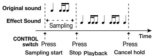
- tr (TRIGGER)
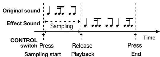
Sampling starts when the CONTROL switch is pressed. When the CONTROL switch is pressed once more, sampling stops and playback starts. If the CONTROL switch is not pressed twice, sampling automatically stops after the delay time has elapsed. Pressing the CONTROL switch once more stops playback.
- Gt (GATE)
Sampling is carried out while the CONTROL switch is being pressed. If the CONTROL switch is not released, sampling automatically stops after the delay time set with parameter 1 + 2 has elapsed, and playback starts. Pressing the CONTROL switch once more stops playback.
So (SOUND ON SOUND)
In this mode, the sampled sound is played back over the current sound. While the CONTROL switch is kept depressed, guitar play sound is added to the playback sound. The delay time set with parameter 1 + 2 determines the duration of the repeat interval.
- The sampled data are retained until the module is set to OFF or the unit is set to the bypass condition.
Parameter 4 HOLD MIX 0-50

Parameter 5 - Parameter 8
See TYPE 1A (CHORUS).
Serves to start and stop the sampling process and to start playback.
TYPE 10A TRM+CHO
This is a combination of tremolo and chorus.
Parameter 1 TRM DPT 0-50
Adjusts the tremolo effect depth.
Parameter 2 TRM RATE 1-50
Adjusts the tremolo effect modulation rate.
Parameter 3 CHO RATE 1-50
Adjusts the chorus effect modulation rate.
Parameter 4 CHO MIX 0-50
Adjusts the chorus sound mix ratio.
Parameter 5 - Parameter 8
See TYPE 1A (CHORUS).

Switches the tremolo on and off.
TYPE 10B RING+VIB
This is a combination of ring modulator and vibrato.
Parameter 1 VIB DPT 0-50
Adjusts the vibrato depth.
Parameter 2 VIB RATE 1-50
Adjusts the vibrato rate.
Parameter 3 RING SPD 1-50
Adjusts the modulation frequency of the ring modulator effect.
Parameter 4 RING BAL 0-50
Adjusts the ring modulator balance.
Parameter 5 - Parameter 8
See TYPE 1A (CHORUS).
Switches the vibrato on and off.
TYPE 11A CUSTOM1
TYPE 11B CUSTOM2
Call up the previously stored custom settings 1/2 for the MOD module. (For information on creating and storing custom settings, see page 18.)
The currently stored parameters can be edited. To retain any changes, store the patch.
DLY/REV (Delay/Reverb) module
This module contains mainly single reverb type effects such as delay and reverb, but it also covers combinations with modulation effects and special effects and contains the jam effect making use of sampling technology.

Indicates a parameter that can be controlled by RTM (see page 30).

Indicates a parameter that can be controlled with the PARM VALUE knob during easy edit (see page 11).

Indicates a parameter for which tap input is possible with the CONTROL switch (see page 31).

[CONTROL SW] indicates an item that can be operated with the CONTROL switch (see page 31).
Common Parameters of DLY/REV Module
RATE
xxMIX
BALANCE
Adjusts the modulation rate.
Adjusts the effect mix ratio.
Adjusts the balance between effect sound and original sound. Higher values result in more pronounced effect sound.
FEEDBACK
SHIFT
Adjusts the amount of feedback.
Adjusts the effect operation direction. "dn" means downward change, and "UP" upward change.
- TYPE 1A and 1B have the same parameters.
TYPE
1A REV HALL
This is a reverb effect simulating concert hall reverb.
TYPE
1B REV ROOM
This is a reverb effect simulating room reverb.
Parameter 1 TIME 1-30
Adjusts the reverber duration (reverb time).
Parameter 2 PRE DLY 0-50
Adjusts the predelay time from the onset of the original sound until the start of reverb.
Parameter 3 TONE 0-10
Adjusts the tone of the effect sound.
Parameter 4 HALL MIX 0-50 (when 1A is selected)
Parameter 4 ROOM MIX 0-50 (when 1B is selected)
Parameter 5 RTM MAX 0-99,1.0
Using the maximum value of the parameter adjusted by RTM as reference (100%) , this parameter adjusts the RTM maximum value in the range from 0% (0) - 100% (1.0).
Parameter 6 RTM MIN 0-99,1.0
Using the maximum value of the parameter adjusted by RTM as reference (100%) , this parameter adjusts the RTM minimum value in the range from 0% (0) - 100% (1.0).
Parameter 7 RTM DES 1-4
Selects the parameter to be adjusted by RTM. Parameter 1 - 4 can be selected.
Parameter 8 RTM CTL oF, Pd, 1 - 5, 8 - 31
Selects the controller to use for RTM. Available settings are "oF" (off), "Pd" (expression pedal), MIDI control change 1 - 5, 8 - 31.
If the effect is ON and the CONTROL switch is operated, the effect will be bypassed while the switch is pushed.
- TYPE 2A and 2B have the same parameters.
TYPE
2A
DLY+HALL
This is a combination of delay and hall reverb.
TYPE
2B
DLY+ROOM
This is a combination of delay and room reverb.
Parameter 1 DLY TIME 1-99,1.0


Sets the delay time in 10-ms units (10 ms x setting value = delay time).
Parameter 2 DLY FB 0-50

Adjusts the amount of delay feedback.
Parameter 3 DLY MIX 0-50

Adjusts the delay sound mix ratio.
Parameter 4 HALL MIX 0-50 (when 2A is selected)


Parameter 4 ROOM MIX
0-50 (when 2B is selected)


Adjusts the reverb sound mix ratio.
Parameter 5 - Parameter 8
See TYPE 1A (REV HALL).
Sets the delay time according to the interval in which the CONTROL switch is operated.
TYPE
3A
PP DLY
This is a ping-pong type delay where the sound is alternately panned right and left. The delay time of 1 millisecond to 6 seconds.
Parameter 1 TIMEx100 0-60


Sets delay time in 100-ms units.
Parameter 2 TIMEx1 0-99


Sets delay time in 1-ms units.
Parameter 3 FEEDBACK 0-50


Parameter 4 PPD MIX 0-50


Parameter 5 - Parameter 8
See TYPE 1A (REV HALL).
Sets the delay time according to the interval in which the CONTROL switch is operated.
TYPE
3B
SEAMLESS
This is an effect where the delay sound continues to be heard for up to 3 seconds after the patch is switched.
- To use the seamless effect, the seamless delay must be selected at the newly called up patch.
Parameter 1 TIME 1-99,1.0-3.0


Sets the delay time. In the range from 1 - 99, the formula is 10 ms x setting value = delay time. In the range from 1.0 - 6.0 (for 3B SEAMLESS, the maximum is 3.0), the formula is 1000ms x setting value = delay time. When the PARM 1 knob is moved, the value changes in steps of 5. For fine adjustment, use the PARM VALUE knob.
Parameter 2 SEAMTIME 1-99,1.0,Hd
Adjusts the duration for which the delay sound is heard after the patch was switched (100 ms x setting value = remain duration). The setting "Hd" means that the delay sound remains for the time set for that patch.
Parameter 3 FEEDBACK 0-50
Parameter 4 SEAM MIX 0-50
Parameter 5 - Parameter 8
See TYPE 1A (REV HALL).
Sets the delay time according to the interval in which the CONTROL switch is operated.
TYPE 4A CHO+DLY
This is a combination effect of chorus and delay.
Parameter 1 TIME 1-99,1.0-6.0
Sets the delay time. In the range from 1 - 99, the formula is 10 ms x setting value = delay time. In the range from 1.0 - 6.0 (for 3B SEAMLESS, the maximum is 3.0), the formula is 1000ms x setting value = delay time. When the PARM 1 knob is moved, the value changes in steps of 5. For fine adjustment, use the PARM VALUE knob (*1).
Parameter 2 DLY MIX 0-50
Adjusts the delay sound mix ratio.
Parameter 3 CHO RATE 1-50
Adjusts the chorus modulation rate.
Parameter 4 CHO MIX 0-50
Adjusts the chorus sound mix ratio.
Parameter 5 - Parameter 8
See TYPE 1A (REV HALL).
Sets the delay time according to the interval in which the CONTROL switch is operated.
TYPE 4B ECHO
This effect creates a soft echo in the style of a tape echo.
Parameter 1 TIME 1-99,1.0-6.0
See (^*1)
Parameter 2 TONE 0-50
Adjusts the effect tone.
Parameter 3 FEEDBACK 0-50
Parameter 4 ECHO MIX 0-50
Parameter 5 - Parameter 8
See TYPE 1A (REV HALL).
Sets the delay time according to the interval in which the CONTROL switch is operated.
TYPE 5A ST CHO
This is a stereo chorus with clear sound and a wide spread.
Parameter 1 DEPTH 0-50
Parameter 2 RATE 1-50
Parameter 3 TONE 0-50
Adjusts the sound quality.
Parameter 4 STCH MIX 0-50
Parameter 5 - Parameter 8
See TYPE 1A (REV HALL).
LED lit: STCH MIX parameter is at maximum. LED out: STCH MIX parameter is at the value stored for that patch.
TYPE 5B AUTO PAN
This effect periodically varies the panpot setting (stereo right/left position) of the sound.
Parameter 1 PAN DPT 0-50
Adjusts the effect width.
Parameter 2 PAN RATE 1-50
Parameter 3 PAN CLIP 0-10
Adjusts the modulation waveform. Higher values result in stronger clipping of waveform tops.
Parameter 4 TRM DPT 0-50
Adjusts the level change depth associated with the panpot setting.
Parameter 5 - Parameter 8
See TYPE 1A (REV HALL).
LED lit: PAN RATE parameter is at maximum. LED out: PAN RATE parameter is at the value stored for that patch.
TYPE 6A PIT+DLY
This is a combination effect where a pitch shifter is applied to the delay sound.
Parameter 1 TIME 1-99,1.0-6.0 TAP
See (^*1)
Parameter 2 PITCH -12-1dt,1-12,24
When set to "dt", the effect is a slight detune from the pitch of the original sound. Other settings shift the pitch by the number of semitones corresponding to the setting.
Parameter 3 FEEDBACK 0-50
Parameter 4 DLY MIX 0-50
Parameter 5 - Parameter 8
See TYPE 1A (REV HALL).
Sets the delay time according to the interval in which the CONTROL switch is operated.
TYPE 6B BEND CHO
This effect provides pitch bending that follows the picking of every note.
Parameter 1 DEPTH 0-50
Adjusts the rate of pitch bend.
Parameter 2 SHIFT dn, UP
Parameter 3 TIME 1-50
Adjusts the predelay time.
Parameter 4 BEND BAL 0-50
Parameter 5 - Parameter 8
See TYPE 1A (REV HALL).
If the effect is ON and the CONTROL switch is operated, the effect will be bypassed while the switch is pushed.
TYPE 7A JAM PLAY
This function lets you record a guitar phrase during a performance and play it back in various ways. For details, see the section "Using Jam Play" on page 32.
Parameter 1 STYLE nM, rS, SC
Selects the playback method of the recorded phrase.
nM (Normal)
Playback in normal direction.
- rS (Reverse)
Performs playback in the reverse direction.
SC (Scratch)
The playback direction changes according to the movement of the expression pedal. Pushing the expression pedal from about the center position down causes normal playback, and moving the pedal in the opposite direction causes reverse playback.
Parameter 2 TRG/GATE tS, tL, GS, GL, rS
Selects the playback mode for foot switch 2.
- tS (Trigger one-shot)
Pressing foot switch 2 causes one-time playback from the beginning, according to the setting of parameter 1. Pressing foot switch 2 during playback stops play.
- tL (Trigger loop)
Pressing foot switch 2 causes loop playback from the beginning, according to the setting of parameter 1. Pressing foot switch 2 during playback stops play.
GS (Gate one-shot)
While foot switch 2 is depressed, the unit performs one-time playback from the beginning, according to the setting of parameter 1. Releasing foot switch 2 during playback stops play.
- GL (Gate loop)
While foot switch 2 is depressed, the unit performs loop playback from the beginning, according to the setting of parameter 1. Releasing foot switch 2 during playback stops play.
- rS (Retrigger one-shot)
Pressing foot switch 2 causes one-time playback from the beginning, according to the setting of parameter 1. Pressing foot switch 2 during playback restarts play.
Parameter 3 MIX 0-50
NOTE:
The JAM PLAY effect does not have an RTM parameter.
Switches the jam play function on and off.
SFX Effects
If one of the SFX effects below is set to ON in the DLY/REV module, the MOD module becomes inactive.

Indicates a parameter that can be controlled by RTM(see page 30).
1 Indicates a parameter that can be controlled with the PARM VALUE knob during easy edit (see page 11).

[CONTROL SW] indicates an item that can be operated with the CONTROL switch (see page 31).
Common Parameters of SFX Effects
PRE DLY
xx MIX
SENS
Adjusts the predelay time.
Adjusts the effect mix ratio.
Adjusts the picking detection sensitivity for wah and the trigger sensitivity.
TYPE 7B SAMPLER
This is a sampler effect with up to 25 seconds of record/play time. For details on operation, see the section "Using the Sampler" (see page 34).
Parameter 1 SOURCE PL, AU
Selects the recording source as follows.
PL:Guitar signal from INPUT jack
AU: Stereo line signal from AUX IN jack
HINT:
When PL is selected, the signal is recorded after passing the EQ module. When AU is selected, the signal is recorded without passing any effect modules.
Parameter 2 PITCH oF, on
This parameter determines whether pitch compensation is performed when playback speed is changed. Available settings are "on" (compensation on) and "oF" (compensation off).
Parameter 3 SPEED 1.0,94,89,84,79,75,71,67,50,25
Selects the playback speed.
When pitch compensation was not selected with the PITCH parameter, the pitch of the playback sound changes as follows according to the SPEED parameter.
| SPEED Parameter value | Playback pitch |
| 1.0 | Original pitch |
| 94 | 1 semitone down - 7 semitones down |
| 89 | |
| 84 | |
| 79 | |
| 75 | |
| 71 | |
| 67 | |
| 50 | 1 octave down |
| 25 | 2 octaves down |
Parameter 4 TONE 10-0-10
Adjusts the playback tone. Settings from -10 to -1 mean a low-range cut and settings from 1 to 10 a high-range cut.
NOTE:
While the sampler function is used, the expression pedal always operates as volume pedal for the input/playback signal. Therefore the SAMPLER effect does not have an RTM parameter.
Switches the sampler function on and off.
TYPE 8A AWA+TRM
This is a combination effect of auto-wah and tremolo.
Parameter 1 AWA SNS -10-1,oF,1-10
Adjusts the auto-wah sensitivity. When set to a negative value, the wah effect operates in the downward direction.
Parameter 2 RISETIME oF,1-50
Adjusts the time lag between the input signal and the start of the tremolo effect. When the setting is "oF", the effect is always operating.
Parameter 3 TRM DPT 0-50

Adjusts the tremolo effect depth.
Parameter 4 TRM RATE 1-50

Adjusts the tremolo modulation rate.
Parameter 5 - Parameter 8
See TYPE 1A (REV HALL).
LED lit: TRM RATE parameter is at maximum.
LED out: TRM RATE parameter is at the value stored for
that patch.
TYPE 8B GATE REV
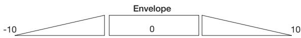
This is a reverb effect for which the envelope (sound change curve) can be adjusted.
Parameter 1 DECAY 1-30
Adjusts the reverb time.
Parameter 2 PRE DLY 0-50
Parameter 3 ENV -10-0-10
Adjusts the reverb sound envelope.
Parameter 4 GATE MIX 0-50
Adjusts the effect sound mix ratio. A value of 50 results in only the effect sound being output.
Parameter 5 - Parameter 8
See TYPE 1A (REV HALL).
If the effect is ON and the CONTROL switch is operated, the effect will be bypassed while the switch is pushed.
TYPE 9A HPS
This is a pitch shifter that allows changing the pitch according to the key of the song.
Parameter 1 KEY C,C#,---A#,b
Selects the keynote of the scale.
Parameter 2 SCALE M3,m3,4t,5t,6t
Sets the harmonic interval from the keynote.
M3 = major third m3 = minor third
4t = complete fourth 5t = complete fifth
6t = major sixth
Parameter 3 SHIFT dn,UP
Adjusts the pitch shift direction. "dn" means downward shift, and "UP" upward shift.
Parameter 4 HPS MIX 0-50
Parameter 5 - Parameter 8
See TYPE 1A (REV HALL).
If the effect is ON and the CONTROL switch is operated, the effect will be bypassed while the switch is pushed.
TYPE 9B TWIN PIT
This effect uses two pitch shifters.
Parameter 1 PITCH 1 -12-1,0F,1-12,24
Sets the pitch of pitch shift 1 in semitones.
Parameter 2 PITCH 2 -12-1,0F,1-12,24
Sets the pitch of pitch shift 2 in semitones.
Parameter 3 MODE Mn/St
Selects monaural (Mn) or stereo (St) operation.
Parameter 4 BALANCE 0-50
Adjusts the effect sound level.
Parameter 5 - Parameter 8
See TYPE 1A (REV HALL).
If the effect is ON and the CONTROL switch is operated, the effect will be bypassed while the switch is pushed.
TYPE 10A SMPLHOLD
This is a sample & hold effect with automatic picking synchronization.
Parameter 1 PATTERN 1-10
Selects the effect pattern.
Parameter 2 SENS 1-20
Select a suitable setting to match the guitar.
Parameter 3 DRY LVL 0-50
Adjusts the level of the original sound.
Parameter 4 WET LVL 0-50
Adjusts the effect sound level.
Parameter 5 - Parameter 8
See TYPE 1A (REV HALL).
If the effect is ON and the CONTROL switch is operated, the effect will be bypassed while the switch is pushed.
TYPE 10B SYNTH
This is an effect that creates a synthesizer type sound.
Parameter 1 COLOR 1-5
Selects the synthesizer sound character.
Parameter 2 SENS 1-20
Parameter 3 DRY LVL 0-50
Adjusts the level of the original sound.
Parameter 4 WET LVL 0-50
Adjusts the level of the synthesizer sound.
Parameter 5 - Parameter 8
See TYPE 1A (REV HALL).
If the effect is ON and the CONTROL switch is operated, the effect will be bypassed while the switch is pushed.
TYPE 11A CUSTOM1
TYPE 11B CUSTOM2
Call up the previously stored custom settings 1/2 for the MOD module. (For information on creating and storing custom settings, see page 18.)
The currently stored parameters can be edited. To retain any changes, store the patch.
TOTAL Module
The TOTAL module is not a separate effect module but rather the section of the unit where patch level and patch name information as well as global parameters common to all patches are stored.
Because the TOTAL module has a high number of parameters, the settings are divided into 3 pages.
[GLOBAL] indicates a global parameter that applies to all patches.
- In edit mode, each push of the TOTAL key changes the color of the flashing TOTAL key LED and the editing target, as follows.
- Flashing red TOTAL module page 1 (patch level, patch name)
- Flashing green TOTAL module page 2 (RTM and CONTROL switch settings)
- Flashing orange TOTAL module page 3 (amp simulator)
TOTAL P1 (Page 1)
Parameter 1 PATCHLVL 1-50
Adjusts the overall patch output level. A setting of 40 results in the unity condition (input level = output level).
Parameter 2 Specifies input position.
Parameter 3 Specifies the character.
PARM knobs 2 and 3 are used to input or change patch names. Use the PARM knob 2 or PARM SELECT knob to specify the character input position (flashing point on display), and use the PARM knob 3 or PARM VALUE knob to select the character or numeral. The following alphanumeric characters can be used.
| (Space) | / | \ | ) | ¥ | + | - | / | ∅ | I | 己 | 3 | 4 |
| (Space) | ' | ( | ) | * | + | - | / | 0 | 1 | 2 | 3 | 4 |
| 5 | 6 | 7 | 8 | 9 | ∠ | = | \ | ? | ∅ | R | B | C |
| 5 | 6 | 7 | 8 | 9 | < | = | > | ? | @ | A | B | C |
| 3 | E | F | 6 | H | I | J | K | L | M | N | ∅ | P |
| D | E | F | G | H | I | J | K | L | M | N | O | P |
| ∅ | R | 5 | T | U | V | W | X | Y | Z | \ | ||
| Q | R | S | T | U | V | W | X | Y | Z | \ | ||
TOTAL P2 (Page 2)
Parameter 1 VOL_RTMOF, on
Determines whether the expression pedal controls the volume. When set to "on", the pedal operates as a volume pedal if RTM is activated.
Parameter 2 CT SW oF, dS, Eq, Md, rv
Selects the module to be controlled by the CONTROL switch.
oF = Not assigned dS = DRIVE module
Eq = EQ module Md = MOD module
rv = DLY/REV module
Parameter 3 CT1 XX xx:OF,1-5,7-31,64-95
Sets the number of the control change (CT1) that is output from the MIDI OUT connector when the patch is switched at the GFX-8.
Select the control change number with the PARM 3 knob and use the PARM VALUE knob to select a value from set 0 - 127 (0 - 99, 0.0...2.7).
Parameter 4 CT2 XX xx:OF,1-5,7-31,64-95
Sets the number of the control change (CT2) that is output from the MIDI OUT connector when the patch is switched at the GFX-8.
Select the control change number with the PARM 4 knob and use the PARM VALUE knob to select a value from set 0 - 127 (0 - 99, 0.0...2.7).
TOTAL P3 (Page 3)
Parameter 1 AMP SIM oF, on
Sets the amp simulator to ON (on) or off (oF).
Parameter 2 AMP TYPE LC, Lb, LS, AC, AS
Selects the amp simulator characteristics to match the connection type.
Line connection
- LC General combo type amplifier
- Lb Bright combo type amplifier
- LS Stack type amplifier
Power amplifier connection
- AC Combo type amplifier
- AS Stack type amplifier
Parameter 3 CABINET oF, C1, C2, ST, WL
Selects the speaker cabinet simulator type.
oF Cabinet simulator OFF
C1 Combo amplifier cabinet with one 12" speaker
C2 Combo amplifier cabinet with two 12" speakers
- ST Stack amplifier with four 10^ speakers
- WL Stack amplifier tower with four 10^ speakers
Parameter 4 CABI DPT 0-10
Adjusts the depth of the cabinet simulator effect.
Using RTM
The RTM (real-time modulation) function can be operated either with the expression pedal on the top panel or by MIDI control change messages input via a MIDI link. This can be used for example to change the reverb sound mix ratio during a performance, using the expression pedal, or to control effect parameters during play, using a MIDI sequencer.
The parameter to be controlled by RTM as well as the control range can be freely set in edit mode. The steps for setting up and using RTM are as follows.
- In play mode, select a patch for which RTM is set.
- Switch to edit mode, and use the DRIVE, ZNR/EQ EDIT, MOD, DLY/REV keys to select the module to be controlled by RTM.
- Turn the PARM SELECT knob until the display shows "RTM CTL".
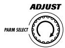
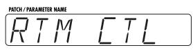
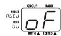
RTM CTL is the parameter that selects the controller for the RTM action. The following settings are possible.
oF
RTM is not used in the module.
Pd
RTM is controlled with the expression pedal on the unit.
1-5,8-31
RTM is controlled with the MIDI control change of the respective control number.
- Turn the PARM VALUE knob to select "Pd".
The respective module can now be controlled with the expression pedal.
- Turn the PARM SELECT knob until the display shows "RTM DES".


RTM DES selects which effect parameter in that module is controlled by RTM.
- Turn the PARM VALUE knob to select the number of the parameter (1 - 4) to be controlled by RTM.
- Turn the PARM SELECT knob until the display shows "RTM MAX", and use the PARM VALUE knob to set the maximum value of the parameter.
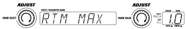
For the effect parameter selected in step 6, RTM MAX determines the maximum value that is established when the expression pedal is pushed fully down (or when the value of the received MIDI control change is 127).
Taking the maximum value of the controlled parameter as 100 (%) , the setting can be made from 0% - 100% (setting value = 0 - 99, 1.0).
- Turn the PARM SELECT knob until the display shows "RTM MIN", and use the PARM VALUE knob to set the minimum value of the parameter.
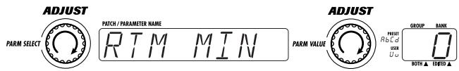
For the effect parameter selected in step 6, RTM MIN determines the minimum value that is established when the expression pedal is fully raised (or when the value of the received MIDI control change is 0).
Taking the maximum value of the controlled parameter as 100 (%) , the setting can be made from 0% - 100% (setting value = 0 - 99, 1.0).

It is also possible to set RTM MIN to a higher value than RTM MAX. For example, if the setting is RTM MAX = 0, RTM MIN = 1.0, the parameter for that module becomes smaller as the pedal is pushed and maximum when the pedal is raised.
- Repeat steps 2 - 8 to make the RTM setting for other modules in the same way.
The RTM parameters described above are available separately for the DRIVE, EQ, MOD, DLY/REV modules. This makes it possible to control several parameters in different modules simultaneously.
It is also possible to assign the volume control to the expression pedal. This setting is made with the VOL_RTM parameter (see page 29) in the TOTAL module.
- Store the patch and return to play mode.
When the expression pedal is operated in this condition, the assigned parameter changes within the preprogrammed range.
When the parameter was set to MAX=1.0 (100%), MIN=0 (0%), the expression pedal changes the parameter as follows.
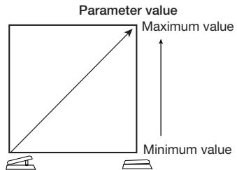
When the parameter was set to MAX=0 (0%), MIN=1.0 (100%), the expression pedal changes the parameter as follows.
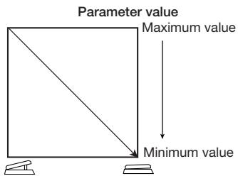
- To switch the effect module being controlled by RTM on and off, push the expression pedal fully down.
The expression pedal of the GFX-8 incorporates a push-down switch that is activated when the pedal is pushed fully down in play mode. The switch serves to turn the RTM controlled module on and off.

For example, use the edit mode to set the DRIVE and MOD modules to RTM control, so that one module is on and the other module is off, and store the patch. When you call up this patch in play mode, you can switch between RTM control of the two modules each time you fully depress the expression pedal.
Using the CONTROL Switch
When the GFX-8 is in manual mode or edit mode, the CONTROL switch (foot switch 4) can be used for real-time control. If you program the module to be controlled beforehand, you can for example use the CONTROL switch during a performance to boost the DRIVE module or to input the delay time with tap input.
- Select the patch for which you want to use the CONTROL switch.
- Press the TOTAL key twice, so that the LED is flashing green.
- Use the PARM knob 2 to assign a module to the CONTROL switch.
While the TOTAL key is flashing green, turning the PARM knob 2 sets the CT SW parameter which selects the module to assign to the CONTROL switch.
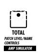
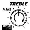
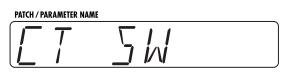
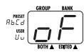
The following settings are available.
- oF CONTROL switch is not active for this patch.
- dS CONTROL switch controls DRIVE module.
- Eq CONTROL switch controls EQ module.
- Md CONTROL switch controls MOD module.
- rv CONTROL switch controls DLY/REV module.

The actual function performed when pressing the CONTROL switch depends on the module and effect (see page 19 - 29).
- Store the patch and return to play mode.
- Hold the BANK DOWN key down for at least 1 second to activate the manual mode.
The function assigned to the CONTROL switch is active in manual mode (and edit mode).
- Push the CONTROL switch.
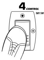
The function assigned to the CONTROL switch in that patch can be carried out. (For each effect, one of the following functions is assigned. This assignment is fixed and cannot be changed.)
- Boost on/off
The switch serves to further boost the DRIVE module. This function can be used for all effects in the DRIVE module.
- Module bypass/Mute
While the CONTROL switch is being pressed, the module effect is bypassed. Can be used for the EQ module and some effects of the MOD and DLY/REV modules.
- Tap input
The delay time setting can be made (edited) by pressing the CONTROL switch in the desired interval. Can be used for delay effects in the MOD and DLY/REV modules.
Parameter value increase/decrease
While the CONTROL switch is being pressed, the rate parameter of the flanger effect etc. becomes maximum.
- To return to the play mode, press the BANK DOWN key once more for at least 1 second.
Using the Jam Play Feature
The GFX-8 incorporates a jam play function which allows you to record and play a guitar phrase of up to 12 seconds in length. Besides straight playback, there are also innovative features such as reverse play and scratch play where you can use the expression pedal to control the direction and speed of playback.
To use the jam play function, prepare a patch which uses the JAM PLAY effect from the DLY/REV module, and make the desired settings for playback method and foot switch operation.
- Select a patch in which you wish to use jam play.
- Switch to edit mode and select JAM PLAY (effect 7A) in the DLY/REV module (see page 26). Make sure that the DLY/REV module is ON.
-
Use the PARM knob 1 to select the desired STYLE parameter (playback method for the recorded phrase).
-
nM (Normal) Playback in normal direction.
- rS (Reverse) Playback in reverse direction.
- SC (Scratch) Playback direction changes according to the movement direction and speed of the expression pedal, resulting in a scratch type effect.
When switching to scratch playback from another playback method, or when switching to another playback method from scratch playback, previous recording data are erased. When scratch playback is selected, the maximum recording time is 2 seconds.
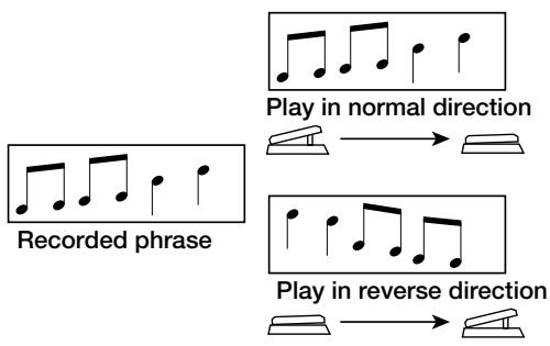
Scratch play
- When the STYLE parameter was set to "nM" (Normal) or "rS" (Reverse), use the PARM knob 2 to select the TRIG/GT parameter (trigger/gate mode).
tS (trigger one-shot)
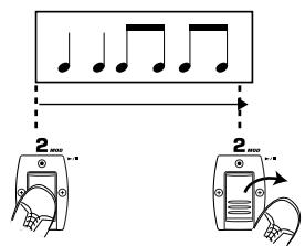
Pressing the / foot switch (foot switch 2) causes one-time playback from the beginning.
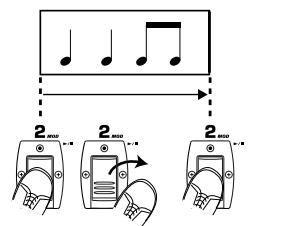
Pressing the foot switch during playback stops play.
tL (trigger loop)
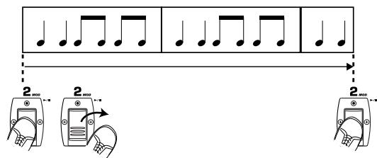
Pressing the / foot switch causes loop playback from the beginning.
Pressing the foot switch during playback stops play.
GS (Gate one-shot)
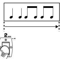
While the / foot switch is pressed, one-time playback from the beginning is carried out.
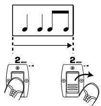
Releasing the foot switch during playback stops play.
GL (Gate loop)
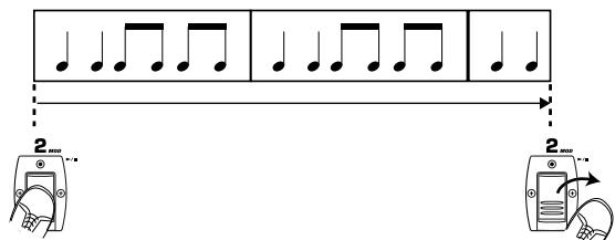
While the / foot switch is pressed, loop playback from the beginning is carried out.
Releasing the / foot switch during playback stops play.
rS (retrigger one-shot)
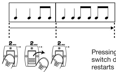
Pressing the foot switch causes one-time playback from the beginning.
Pressing the / foot switch during playback restarts play.
When the STYLE parameter is set to "SC", this parameter has no effect.

When the JAM PLAY effect is selected for the DLY/REV module, the expression pedal and CONTROL switch are automatically assigned to the jam play feature.
- Store the patch and return to play mode.
In play mode, when a patch is selected where jam play can be used, the DLY/REV key flashes.
- To activate jam play, push the expression pedal fully down in play mode, or press the CONTROL switch in manual mode.
The GFX-8 enters the jam play mode and goes into the recording standby condition. The display shows "STOP", and "JP" flashes on the GROUP/BANK indicator.
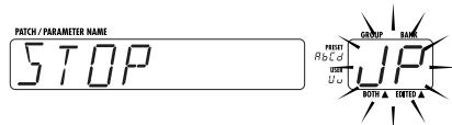
- While playing your instrument, press the REC foot switch (foot switch 3).
The indication "RECORDING" scrolls on the display and recording starts.
For jam play, the recording source signal is always the processed effect signal. When "nM" or "rS" is selected as STYLE parameter, the expression pedal can be used to adjust the input signal level.
- To stop recording halfway, press the / foot switch (foot switch 2).
Recording stops, and playback starts according to the selected settings.
When the / foot switch was not operated, recording stops automatically after 12 seconds have elapsed, and playback starts according to the selected settings.
- Use the / foot switch (foot switch 2) and expression pedal to control playback/stop of the recorded phrase.
When "SC" was selected as STYLE parameter, the expression pedal can be used for scratch playback. If "nM" or "rS" was selected as STYLE parameter, the expression pedal can be used to control the jam play volume.
To record a new phrase, repeat steps 7 - 9.
- To terminate jam play, press the expression pedal once more fully down, press the EDIT key, or press the CONTROL switch.
Using the Sampler
The GFX-8 incorporates a sampler with a maximum recording duration of 25 seconds. It can be used not only to record the guitar input but also the signal from an external component such as a CD player or similar. The recorded sample is stored in memory and can be easily played back using the foot switches.
- Refer to the diagram on page 6 and connect the recording source to the INPUT jack or AUX IN jack of the GFX-8.

Before changing any connections, be sure to turn the OUTPUT knob fully to zero. If plugs are inserted or removed with the OUTPUT turned up, transient noise can occur which can damage the speakers of the playback system.
- Select the patch in which you wish to use the sampler.
- Switch to edit mode and select SAMPLER (effect 7B) in the DLY/REV module (see page 27). Make sure that the DLY/REV module is ON.

When S AMPLER is selected for the DLY/REV module, the MOD module is automatically set to OFF.
- Use PARM knobs 1 - 4 to select the sampler parameters, as follows.
PARM knob 1 SOURCE parameter (recording source selection)
The following settings are available.
- PL = Guitar signal from INPUT jack (after passing EQ module/amp simulator)
- AU = Signal from AUX IN jack (signal does not pass any effect module)
PARM knob 2 PITCH parameter (pitch compensation)
Sets pitch compensation to ON (on) or OFF (oF). When the PITCH parameter is ON, the pitch will be kept constant also when changing the playback speed with the SPEED parameter (PARM knob 3).
PARM knob 3 SPEED (playback speed)
Sets the sampler playback speed. When pitch compensation is not carried out with the PITCH parameter, the pitch changes as follows, according to the SPEED parameter.
1.0 original pitch
94,89,84,79,75,71,67
(1 semitone down - 7 semitones down)
- 50 (1 octave down)
25 (2 octaves down)
PARM knob 4 TONE
Adjusts the playback tone. Settings from -10 to -1 mean a low-range cut and settings from 1 to 10 a high-range cut.
- Store the patch and return to play mode.
For patches where SAMPLER is selected as effect for the DLY/REV module, the DLY/REV key LED flashes green.
- To activate the sampler, push the expression pedal fully down in play mode, or press the CONTROL switch in manual mode.
The following information appears on the display and the indication "SM" flashes on the GROUP/BANK indicator.
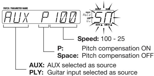
- Press the REC foot switch (foot switch 3) and play the phrase you want to record (or start playback at the CD player or other external device).
The indication "RECORDING" scrolls on the display and recording starts.
- To stop recording halfway, press the / foot switch (foot switch 2).
When the / foot switch is pressed, playback starts immediately from the beginning of the recorded phrase.
When the / foot switch was not operated, recording stops automatically after 25 seconds have elapsed, and playback starts.
During playback, the display shows the following information.

When recording is complete, the foot switches 1 - 4 can be used to perform the following operations.
foot switch (foot switch 1) Rewind
/ 串 foot switch (foot switch 2) Playback start/stop
REC foot switch (foot switch 3) Clear recorded phrase and start new recording CONTROL switch (foot switch 4) Terminate sampler mode
- To terminate the sampler function, press the expression pedal once more fully down, press the EDIT key, or press the CONTROL switch.

The recorded contents are cleared when the sampler function is terminated.
This section describes various application examples of the GFX-8 using MIDI.
Basic MIDI Send/Receive Settings
Before using the various possibilities, basic settings for sending and receiving MIDI messages (Omni mode on/off, send/receive channel, etc.) must be made, as described below. MIDI settings are global parameters that apply to all patches. The settings are memorized also when the unit is turned off.
1. In play mode or edit mode, press the MIDI key.
The MIDI key lights up, and the unit enters the MIDI utility mode. The GROUP/BANK indicator shows the setting item number, and the display shows the setting value.
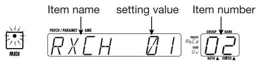
2. Use the PARM SELECT knobs 1 - 4 to select the item, and use the PARM VALUE knob to change the value.
Item numbers, setting contents, and setting values are listed below.
01 RXCH (MIDI receive channel)
Setting value: 01 - 16
Sets the MIDI channel in which the GFX-8 receives MIDI messages.
02 TXCH (MIDI send channel)
Setting value: 01 - 16
Sets the MIDI channel in which the GFX-8 sends MIDI messages.
03 MIDI OUT/THR (MIDI OUT connector function)
Setting value: OUT, THR
Sets the function of the MIDI OUT connector to "OUT" (MIDI OUT connector) or "THR" (MIDI THRU connector). When wishing to transmit GFX-8 operation information to an external device, select "OUT".

When MIDI THRU is selected, the GFX-8 will not send out any MIDI messages, and all functions related to MIDI message output are disabled.
3. When the settings are complete, press the EDIT key.
The settings are stored, and the unit returns to the play mode.
Switching GFX-8 Patches From an External Unit
You can send MIDI messages from an external MIDI device to the GFX-8 and switch patches at the GFX-8 in this way. To do this, connect the MIDI OUT connector of the external MIDI device to the MIDI IN jack of the GFX-8, using a MIDI cable. Set the MIDI send channel at the external MIDI device and the MIDI receive channel (RXCH) at the GFX-8 to the same settings.
To switch patches, you can either use bank select + program change information to switch the patch directly, or you can use the program change map built into the GFX-8 to call up patches indirectly.
■ Specifying Patches Directly
You can use bank select + program change messages to directly specify any group, bank number, and patch number of the GFX-8. Proceed as follows.
1. In play mode or edit mode, press the MIDI key.
The MIDI key lights up, and the unit enters the MIDI utility mode.
2. Turn the PARM SELECT knob so that the GROUP/BANK indicator shows "14".
The display shows "PC FIX" or "PC MAP".
3. If necessary, use the PARM VALUE knob so that the display shows "PC FIX", and then press the EDIT key.
The GFX-8 returns to the play mode.
4. To switch GFX-8 patches under external control, send messages in the following order.
- Bank select MSB (control change number: 0/value: 0)
Bank select LSB (control change number: 32/value: 0 - 2)
Program number (0 - 79)
The relationship between GFX-8 patches and bank select MSB/bank select LSB/program number is as shown below.
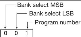
| GROUP/BANK | PATCH NO. | GROUP/BANK | PATCH NO. | ||||||||||||||
| 1 | 2 | 3 | 4 | 1 | 2 | 3 | 4 | ||||||||||
| U0 | 0 | 0 | 0 | 0 | 1 | 0 | 0 | 2 | 0 | 0 | 3 | u0 | 0 | 0 | 40 | 0 | 41 |
| U1 | 0 | 0 | 4 | 0 | 5 | 0 | 0 | 6 | 0 | 0 | 7 | u1 | 0 | 0 | 44 | 0 | 45 |
| U2 | 0 | 0 | 8 | 0 | 9 | 0 | 0 | 10 | 0 | 0 | 11 | u2 | 0 | 0 | 48 | 0 | 49 |
| U3 | 0 | 0 | 12 | 0 | 13 | 0 | 0 | 14 | 0 | 0 | 15 | u3 | 0 | 0 | 52 | 0 | 53 |
| U4 | 0 | 0 | 16 | 0 | 17 | 0 | 0 | 18 | 0 | 0 | 19 | u4 | 0 | 0 | 56 | 0 | 57 |
| U5 | 0 | 0 | 20 | 0 | 21 | 0 | 0 | 22 | 0 | 0 | 23 | u5 | 0 | 0 | 60 | 0 | 61 |
| U6 | 0 | 0 | 24 | 0 | 25 | 0 | 0 | 26 | 0 | 0 | 27 | u6 | 0 | 0 | 64 | 0 | 65 |
| U7 | 0 | 0 | 28 | 0 | 29 | 0 | 0 | 30 | 0 | 0 | 31 | u7 | 0 | 0 | 68 | 0 | 69 |
| U8 | 0 | 0 | 32 | 0 | 33 | 0 | 0 | 34 | 0 | 0 | 35 | u8 | 0 | 0 | 72 | 0 | 73 |
| U9 | 0 | 0 | 36 | 0 | 37 | 0 | 0 | 38 | 0 | 0 | 39 | u9 | 0 | 0 | 76 | 0 | 77 |
| GROUP/BANK | PATCH NO. | GROUP/BANK | PATCH NO. | ||||||||||||||
| 1 | 2 | 3 | 4 | 1 | 2 | 3 | 4 | ||||||||||
| A0 | 0 | 1 | 0 | 0 | 1 | 1 | 0 | 1 | 2 | 0 | 1 | 3 | b0 | 0 | 1 | 40 | 0 |
| A1 | 0 | 1 | 4 | 0 | 1 | 5 | 0 | 1 | 6 | 0 | 1 | 7 | b1 | 0 | 1 | 44 | 0 |
| A2 | 0 | 1 | 8 | 0 | 1 | 9 | 0 | 1 | 10 | 0 | 1 | 11 | b2 | 0 | 1 | 48 | 0 |
| A3 | 0 | 1 | 12 | 0 | 1 | 13 | 0 | 1 | 14 | 0 | 1 | 15 | b3 | 0 | 1 | 52 | 0 |
| A4 | 0 | 1 | 16 | 0 | 1 | 17 | 0 | 1 | 18 | 0 | 1 | 19 | b4 | 0 | 1 | 56 | 0 |
| A5 | 0 | 1 | 20 | 0 | 1 | 21 | 0 | 1 | 22 | 0 | 1 | 23 | b5 | 0 | 1 | 60 | 0 |
| A6 | 0 | 1 | 24 | 0 | 1 | 25 | 0 | 1 | 26 | 0 | 1 | 27 | b6 | 0 | 1 | 64 | 0 |
| A7 | 0 | 1 | 28 | 0 | 1 | 29 | 0 | 1 | 30 | 0 | 1 | 31 | b7 | 0 | 1 | 68 | 0 |
| A8 | 0 | 1 | 32 | 0 | 1 | 33 | 0 | 1 | 34 | 0 | 1 | 35 | b8 | 0 | 1 | 72 | 0 |
| A9 | 0 | 1 | 36 | 0 | 1 | 37 | 0 | 1 | 38 | 0 | 1 | 39 | b9 | 0 | 1 | 76 | 0 |
| GROUP/BANK | PATCH NO. | GROUP/BANK | PATCH NO. | ||||||||||||||
| 1 | 2 | 3 | 4 | 1 | 2 | 3 | 4 | ||||||||||
| C0 | 0 | 2 | 0 | 0 | 2 | 1 | 0 | 2 | 2 | 0 | 2 | 3 | d0 | 0 | 2 | 40 | 0 |
| C1 | 0 | 2 | 4 | 0 | 2 | 5 | 0 | 2 | 6 | 0 | 2 | 7 | d1 | 0 | 2 | 44 | 0 |
| C2 | 0 | 2 | 8 | 0 | 2 | 9 | 0 | 2 | 10 | 0 | 2 | 11 | d2 | 0 | 2 | 48 | 0 |
| C3 | 0 | 2 | 12 | 0 | 2 | 13 | 0 | 2 | 14 | 0 | 2 | 15 | d3 | 0 | 2 | 52 | 0 |
| C4 | 0 | 2 | 16 | 0 | 2 | 17 | 0 | 2 | 18 | 0 | 2 | 19 | d4 | 0 | 2 | 56 | 0 |
| C5 | 0 | 2 | 20 | 0 | 2 | 21 | 0 | 2 | 22 | 0 | 2 | 23 | d5 | 0 | 2 | 60 | 0 |
| C6 | 0 | 2 | 24 | 0 | 2 | 25 | 0 | 2 | 26 | 0 | 2 | 27 | d6 | 0 | 2 | 64 | 0 |
| C7 | 0 | 2 | 28 | 0 | 2 | 29 | 0 | 2 | 30 | 0 | 2 | 31 | d7 | 0 | 2 | 68 | 0 |
| C8 | 0 | 2 | 32 | 0 | 2 | 33 | 0 | 2 | 34 | 0 | 2 | 35 | d8 | 0 | 2 | 72 | 0 |
| C9 | 0 | 2 | 36 | 0 | 2 | 37 | 0 | 2 | 38 | 0 | 2 | 39 | d9 | 0 | 2 | 76 | 0 |

- Always use the sequence: bank select MSB, bank select LSB, program number. If the order is changed or if another message is inserted, the GFX-8 may disregard the command.
- When bank select information is omitted and the GFX-8 receives only a program number, it will use the last received bank select (default settings: MSB = 0, LSB = 0).
■ Specifying Patches Via PC Map
The GFX-8 incorporates a so-called program change map that maps MIDI program numbers to GFX-8 patches. Using the program change map, you can make program change numbers 0 - 127 call up any desired patch.
- In play mode or edit mode, press the MIDI key.
The MIDI key lights up, and the unit enters the MIDI utility mode.
- Turn the PARM SELECT knob so that the GROUP/BANK indicator shows "14".
The display shows "PC FIX" or "PC MAP".
- Turn the PARM VALUE knob until the display shows "PC MAP".
The program change map is now active.
- Next, turn the PARM SELECT knob until the GROUP/BANK indicator shows "PC".
The program change map is selected as setting item. The display shows the MIDI program number (P000 - P127) and the group (U, u, A, b, C, d), bank number (0 - 9), and patch number (1 - 4) assigned to that number.
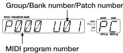
- Turn the PARM SELECT knob to select the program number to assign to the patch.
When the above display has appeared, you can turn the PARM SELECT knob to change the program number.

- Turn the PARM VALUE knob to select the group, bank number, and patch number to assign to the currently shown program number.

You can use the BANK UP/DOWN foot switch and foot switches 1 - 4 to specify the respective group, bank number, and patch number.
- Repeat steps 5 and 6 until all desired program numbers have been mapped to their respective patches.
If desired, you can also assign several program numbers to the same patch.
- When the entire assignment process is completed, press the EDIT key.
The program change map is stored, and the unit returns to the play mode.
- Send a program change message from the external MIDI device.
The patch assigned to the program number will be called up.

- When using the program change map, there is no need to send bank select information from the external MIDI device.
- The program change map is active only for receiving MIDI messages. The program number information sent by the GFX-8 when patches are switched is fixed (see page 36).
Controlling External Devices in Conjunction With GFX-8 Patch Switching
When you switch a patch with the controls on the top panel of the GFX-8, the unit can send program change information and control change information to an external MIDI device. To do this, connect the MIDI OUT connector of the GFX-8 to the MIDI IN jack of the external MIDI device, using a MIDI cable. Set the MIDI send channel at the GFX-8 and the MIDI receive channel (RXCH) at the external MIDI device to the same settings.
This function of the GFX-8 can be set up in two ways, as follows:
GFX-8 sends only bank select information + program change information when the patch is switched GFX-8 sends bank select information + program change information followed by two types of control change information (CT1 + CT2).
To Send Only Bank Select + Program Change Information
To set up the GFX-8 so that it sends bank select information + program change information corresponding to a patch, proceed as follows. This is useful for example to switch programs at a MIDI compatible amplifier or effect device when a patch is switched at the GFX-8.
- In play mode or edit mode, press the MIDI key.
The MIDI key lights up, and the unit enters the MIDI utility mode.
- Turn the PARM SELECT knob so that the GROUP/BANK indicator shows "04".
The display shows "PCOUT ON" or "PCOUT OF".
- If required, turn the PARM VALUE knob so that the display shows "PCOUT ON", then press the EDIT key.
The program change output is now enabled, and the GFX-8 returns to the play mode.
- Switch a patch at the GFX-8. The bank select MSB, bank select LSB, and program change corresponding to that bank is output.
For information on the relationship between GFX-8 patches and bank select MSB/bank select LSB/program number, see the table on page 36.
To Send Control Change Information
Besides pedal and foot switch operation, the GFX-8 can be set up so that it sends two types of control change information (called CT1 and CT2) immediately after sending bank select + program change information when a patch is changed. The control number and value of CT1 and CT2 can be defined freely and stored separately for each patch. For example, this is useful to control the volume setting at a MIDI compatible amplifier or synthesizer.
- In play mode or edit mode, press the MIDI key.
The MIDI key lights up, and the unit enters the MIDI utility mode.
- Turn the PARM SELECT knob so that the GROUP/BANK indicator shows "05".
The display shows "CTOUT ON" or "CTOUT OF".
- If required, turn the PARM VALUE knob so that the display shows "CTOUT ON", then press the EDIT key.
The control change output is now enabled, and the GFX-8 returns to the play mode.

This setting affects all control change output operations of the GFX-8.
- Press the TOTAL key twice, so that the LED flashes green.
Page 2 of the TOTAL module can now be edited.
- Turn PARM knob 3 and select the control number for CT1 (control change sent immediately after program change).
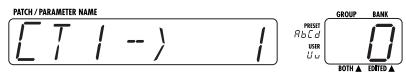
The display shows "CT1->XX" (XX is the control number), and the GROUP/BANK indicator shows the value. Use PARM knob 3 to set the control number for CT1. Available settings are of F (OF), 1 - 5, 7 - 31, 64 - 95.
-
Turn the PARM VALUE knob to set the value for CT1 to 0 - 127 (0 - 99, 0.0...2.7).
-
Turn PARM knob 4 to select the control number for CT2 (second control change sent after program change).

- Turn the PARM VALUE knob to set the value for CT1 to 0 - 127 (0 - 99, 0.0...2.7).
- Store the patch and return to play mode.
- Call up the respective patch.
The following MIDI message sequence is output from the MIDI OUT connector: bank select MSB bank select LSB program change CT1 CT2.
Remote Control Using GFX-8
It is possible to send out MIDI control change information whenever a control on the GFX-8 is operated, or conversely, to operate the GFX-8 via externally supplied control change information. This lets you for example record a GFX-8 operation sequence on a MIDI sequencer and play it back at any time. Remote control of the GFX-8 from other external equipment is also possible.
To control external equipment from the GFX-8, connect the MIDI OUT connector of the GFX-8 to the MIDI IN connector of the external device. To control the GFX-8 from external equipment, connect the MIDI OUT connector of the external device to the MIDI IN connector of the GFX-8. (For information on enabling or disabling control change information output, please refer to "To Send Control Change Information" on page 37.)
- In play mode or edit mode, press the MIDI key.
The MIDI key lights up, and the unit enters the MIDI utility mode.
- Use the PARM SELECT knob to select items 6 - 13, and use the PARM VALUE knob to change the setting value.
The item numbers, setting contents, and setting values are shown below.
06
EXPP (expression pedal send control number)
setting value: OF, 1 - 5, 7 - 31
Sets the control number for the control change information sent when the expression pedal is operated.

This is a send-only parameter. The internal parameter setting of the GFX-8 is not affected also when the GFX-8 receives this control number.
07
DRIVE (DRIVE module on/off receive control number)
Setting values: OF, 64 - 95
08
MOD (MOD module on/off receive control number)
Setting values: OF, 64 - 95
09
D/R (DLY/REV module on/off receive control number) Setting values: OF, 64 - 95
10
EQ (EQ module on/off receive control number)
Setting values: OF, 64 - 95
Sets the control number that is sent when a module is switched on and off at the GFX-8. The respective module is also switched when the GFX-8 receives that control change information from an external device.
11
BYPAS (bypass operation receive control number) Setting values: OF, 64 - 95
12
MUTE (mute operation receive control number)
Setting values: OF, 64 - 95
Set the control number that is sent when bypass/mute is switched on and off at the GFX-8. Bypass/mute is also switched when the GFX-8 receives that control change information from an external device.
13
CTSW (CONTROL switch operation receive control number)
Setting values: OF, 64 - 95
Sets the control number that is sent when the CONTROL
switch is operated at the GFX-8.
3. When the setting is complete, press the EDIT key to return to play mode.
When panel keys or switches are operated in this condition, the respective control change is output from the MIDI OUT connector. When a control change message is received from external equipment, the respective item changes. The values that can be received for the various items are listed below.
Example:
Control number 70 is assigned to DRIVE module on/off
When the DRIVE module is switched on or off at the GFX-8 itself, the MIDI OUT connector supplies the following control change information: control number = 70 , value = 127/0 .
When the control change information "control number = 70, value = 127/0" is supplied to the GFX-8 MIDI IN connector, the DRIVE module is switched OFF. When the control change information "control number = 70, value = 64 - 127" is supplied, the DRIVE module is switched ON.

While the jam play function or sampler function is activated, external MIDI control is not possible.
| Allowable values | Allowable values | |
| EXPP | 0 - 127 Continuously variable | -- |
| DRIVE/MOD DLY/REV/EQ | 0=OFF/127=ON | 0 - 63=OFF/64 - 127=ON |
| BYPAS/MUTE | 0=OFF/127=ON | 0 - 63=OFF/64 - 127=ON |
| CTSW (For tap input) | When pushed: 127 = ON value output | -- |
| Immediately after: 0 = OFF value output | -- | |
| CTSW (when using push = ON function) | When pushed: 127 = ON value output | -- |
| When released: 0 = OFF value output | -- | |
| CTSW (when using push = ON/OFF toggle function) | When pushed and LED lights: 127 = ON value output | -- |
| When pushed and LED goes out: O = OFF value output | -- |
Bulk Dump
Patch information and program change map information stored in the GFX-8 can be output in bulk via the MIDI link. This function is called "bulk dump". You can use this function for example to store GFX-8 information on a MIDI sequencer or to exchange settings between two GFX-8 units.
- Connect the MIDI OUT connector of the GFX-8 to the MIDI IN connector of the external MIDI device (other GFX-8, MIDI sequencer, etc.).
- Set the GFX-8 to play mode and turn the PARM SELECT knob until the GROUP/BANK indicator shows "15".
-
Use the PARM VALUE knob to select the data type to use for the bulk dump operation.
-
ALL All settings of GFX-8
- PAT All patch data
- SYS All settings of GFX-8 except patch data
- BUF Currently selected patch
-
DST DRIVE module user custom settings
-
After setting the external MIDI device to the recording mode, press the STORE key.
For example, when "ALL" was selected in step 3, the display shows "ALL OK?".
- To execute the bulk dump operation, press the STORE key once more.
The display shows "DUMPING" and the GFX-8 starts to send the bulk dump data. To cancel the bulk dump operation, press the EDIT/CANCEL key before pressing the STORE key the second time. The unit returns to the play mode without carrying out the operation.
- When the GFX-8 has returned to play mode, stop recording at the external MIDI device.
Perform any necessary steps to store the recorded information on the external MIDI device.
Bulk Load
GFX-8 patch information or program change map information stored on external equipment can be reloaded into the GFX- 8. This is called "bulk load".
- Connect the MIDI OUT connector of the external MIDI device (other GFX-8, MIDI sequencer, etc.) to the MIDI IN connector of the GFX-8.

To perform bulk load, the GFX-8 must be set to the same MIDI channel as used when performing bulk dump. If the MIDI channel is different, playback at the external MIDI device will have no effect and will be disregarded by the GFX-8. When the GFX-8 is in store mode, received bulk data will be disregarded. Verify that the unit is not in store mode before proceeding.
- Perform playback at the external MIDI device.
The settings of the GFX-8 are overwritten, depending on the type of received data.

- When saving data on an external device and when reloading the data to the GFX-8, the GFX-8 must be set to the same MIDI channel. If the MIDI channel is different, playback at the external MIDI device will have no effect and will be disregarded by the GFX-8.
-
Playback at the external MIDI device must be performed at the same tempo as recording. If the tempo is faster, the GFX-8 may not receive the data properly.
-
When bulk load is completed, stop playback at the external MIDI device.

When performing bulk dump or load with two GFX-8 units, hooking up both the MIDI IN and MIDI OUT connectors will result in faster data transfer.
Supplied Software
The GFX-8 comes with a CD-ROM that contains software for editing patches on a personal computer. (The disc contains versions for Windows 95/98 and Macintosh.) The software comprises the following functions.
(1) Patch librarian
Serves to manage patch information of the GFX-8 on the computer. Information about all patches of the GFX-8 is sent to the computer via a MIDI link and can be stored on the hard disk as a project file. Within a project, the order of patches can be changed, and information stored as project files can be loaded back into the GFX-8. In effect, this increases the memory capacity of the GFX-8 to an unlimited size.
(2) Visual editor
Using knobs, switches and other graphical elements appearing on the computer screen, patches contained in project files can be edited. Because the edited contents are sent immediately to the GFX-8 via the MIDI link, the effect of any editing operation can be checked immediately by listening to the sound. Edited patches can be stored on the computer and can also be sent to the GFX-8 via the MIDI link.
(3) DRIVE module custom setting editor
Using this software, you can edit additional parameters for the DRIVE module custom settings, to achieve even more detailed adjustments than are possible with the controls on the unit itself. There are virtually no limits to your creativity, as you can set numerous items such as balance for each frequency band, distortion circuit characteristics, etc. The editing results can be written back to the GFX-8.
- For information on software installation, please refer to the separate sheet. For information on how to use the software, please refer to the documentation included on the CD-ROM.
- The latest version of the software can be downloaded from the Zoom web site.
URL: http://wwwzoom.co.jp
Other Functions
This section contains information about special functions such as how to return the GFX-8 to the factory default condition and how to readjust the expression pedal.
All Initialize/Factory Recall
The All Initialize/Factory Recall function is a special function that lets you reset the GFX-8 to the condition in which it was originally shipped. When All Initialize is performed, all settings of the unit including all user group patches are returned to the default condition. Factory Recall can be used to reset only specific user group patches group to the default settings.
- Turn power to the GFX-8 on while keeping the STORE key depressed.
The display shows "ALL-INIT".
- To perform All Initialize
Continue with the next step. -
To perform Factory Recall
Use the BANK UP/DOWN foot switch and foot switches 1 - 4 to select the patch (from a user group) that you want to return to the factory default condition. -
Press the STORE key once more
All Initialize or Factory Recall is carried out. If All Initialize was carried out, the unit automatically returns to the play mode.
Note that when All Initialize is executed, the contents of all patches stored by the user will be overwritten (erased). When wishing to cancel All Initialize/Factory Recall, press the EDIT/CANCEL key before step 2.
Trying Out the Factory Default Patches (Self Introduction Function)
The GFX-8 also incorporates a so-called self introduction function that automatically switches patches to demonstrate the capabilities of the unit.
- To activate the function, hold down the TOTAL key while turning on power to the unit.
The GFX-8 starts to automatically cycle through the factory-default patches.
The indication "SELF INTRODUCTION" and the currently selected patch name are scrolled on the display. You can play your guitar while checking out the various patches.
- To stop the self introduction function, press the EDIT/CANCEL key.
Adjusting the Expression Pedal
The expression pedal of the GFX-8 uses a highly reliable optical sensor mechanism. The pedal is adjusted for optimum operation at the factory, but it can be readjusted as follows If required.
- Hold down the GROUP key while turning on power to the unit.
The indication "MIN" appears on the display.
- With the expression pedal fully raised, press the STORE key.
The display indication changes to "MAX".
- Push the expression pedal down until it touches the stopper and then release the pedal. Press the STORE key at this point.
The adjustment is completed, and the unit returns to the play mode.
Disabling the Bypass/Mute Function
If desired, the setup of the unit can be changed so that the bypass/mute condition will not be activated also when the foot switch with the lit LED is pushed. This can help to prevent inadvertently switching to bypass/mute. To make the setting, proceed as follows.
- Hold down the MIDI key while turning on power to the unit.
The display shows "BYP ENTR", and depending on the current setting, the indication "En" (bypass/mute function enabled) or "dS" (bypass/mute function disabled) is shown on the GROUP/BANK indicator.
- Use the PARM VALUE knob to select the desired setting.
- Press the STORE key.
The setting is stored and the GFX-8 switches to the play mode. If you press the CANCEL key instead of the STORE key, no change is made and the GFX-8 switches to the play mode.
Troubleshooting
| Symptom | Check | Remedy |
| No sound or very low volume | ● Is correct AC adapter connected, and is power switch turned on? | Turn the system on as described in "Preparations". |
| ● Are connections between INPUT jack and instrument, OUTPUT jack and playback system established correctly? | Follow the instructions in "Getting Connected". | |
| ● Is shielded cable defective? | Try replacing the cable. | |
| ● Is playback system turned on? Are all volume controls at instrument and amplifier etc. set to proper levels? | Check all devices and adjust controls. | |
| ● Is expression pedal raised? | For some patches, the expression pedal controls the volume. Set it to a suitable position. | |
| ● Is GFX-8 set to mute condition? | Cancel the mute condition. | |
| Recording/playback not possible in jam play mode | ● Are you trying to record from CD player connected to AUX IN jack? | Jam play can only record signals from INPUT jack. |
| ● Is expression pedal raised? | In jam play mode, expression pedal is used to adjust record/playback volume. Set pedal to a suitable position. | |
| Recording/playback not possible in sampler mode | ● Is recording source selected correctly? | Set SOURCE parameter to a suitable setting. |
| ● Is expression pedal raised? | In sampler mode, expression pedal is used to adjust playback volume. Set pedal to a suitable position. | |
| Cannot send MIDI information | ● Is MIDI OUT connector function set to "MIDI THRU"? | Set connector function to "MIDI OUT". |
| Cannot receive MIDI information | ● Is jam play/sampler function being used? | In jam play/sampler mode, no MIDI information is accepted. |
GFX-8 Specifications
Number of effect programs
69 (67 effects + amp simulator + ZNR)
Number of effect modules
4 + amp simulator ^+ ZNR
Sampler function
Maximum recording time 25 seconds
Variable playback speed
Patch memory capacity
USER: 20 banks x 4 = 80 (read/write)
PRESET: 40 banks x 4 = 160
Total 240 patches
Sampling frequency
40 kHz
A/D converter
20 bit, 64 times oversampling
D/A converter
20 bit, 128 times oversampling
Inputs
Guitar input
Standard monaural phone jack (Rated input level: -10 dBm, input impedance: 470 kilohms)
External return
Standard monaural phone jack (Rated input level: -10 dBm, input impedance: 470 kilohms)
AUX IN
Mini phone jack (stereo) (Input impedance: 10 kilohms)
Reference input level: -10 dBm to +4 dBm
Outputs
Line output
Standard monaural phone jack x 2 = stereo (Rated output level: +4 dBm, output load impedance: 10 kilohms or more)
Control connectors
Headphone output
Standard stereo phone jack
External send
Control connectors
(Rated output level: -10 dBm, output load impedance: 10 kilohms or more)
Display
MIDI OUT, MIDI IN
Power requirements
8-digit alphanumeric LED display 2-digit 7-segment LED display
Dimensions
12 V AC (from supplied AC adapter AD-0008)
Weight
455 (W) x 203 (H) x 80 (D) mm
3.6kg
- 0 dBm = 0.775 Vrms
- Design and specifications subject to change without notice.
MIDI Implimentation Chart
[ GUITAR EFFECT PROCESSOR ]
Model GFX-8
MIDI Implementation Chart
Date: 28.SEP.1999
Version :1.00
| Function ... | Transmitted | Recognized | Remarks | |
| Basic Channel Changed | 1-16 | 1-16 | Memorized | |
| 1-16 | 1-16 | |||
| Mode Altered | 3 | 3 | ||
| x | x | |||
| ********** | ********** | |||
| Note Number | True voice | x | x | |
| Velocity Note ON | x | x | ||
| Note OFF | x | x | ||
| After Key's Touch Ch's | x | x | ||
| x | x | |||
| Pitch Bend | x | x | ||
| Control Change | 0 | 0 | Bank select Volume RTM control Effect module on/off Signal mute All bypass Pedal control CONTROL switch | |
| 1-5,7-31 (*1) 64-95 (*1) 64-95 64-95 1-5,7-31 64-95 | 1-5,8-31 64-95 64-95 64-95 | |||
| Prog Change | True # | o (0-79) | o (0-127) | Internally mappable Total 240 programs |
| ********** | U0.1-u9.4,A0.1-d9.4 | |||
| System Exclusive | o | o | ||
| System Common | Song Pos Song Sel Tune | x | x x x | |
| x | x | |||
| x | x | |||
| System Real Time | Clock Commands | x | x x | |
| x | x | |||
| Aux Mes-sages | Local ON/OFF All Notes OFF Active Sense Reset | x | x x x | |
| x | x x x | |||
| x | x | |||
| Notes (*1) Transmits the patch default value when program changes. | ||||
Mode 1 : OMNI ON, POLY
Mode 2 : OMNI ON, MONO
o : Yes
Mode 3 : OMNI OFF, POLY
Mode 4 : OMNI OFF, MONO
x : No
ZEEM
ZOOM CORPORATION
ITOHPIA Iwamotocho 2chome Bldg. 2F, 2-11-2, Iwamoto-cho, Chiyoda-ku, Tokyo 101-0032, Japan
Web Site: http://wwwzoomo.co.jp
USER
| BANK | PATCH 1 | PATCH 2 | PATCH 3 | PATCH 4 | |
| U0 | DEMO | GFX DRV | MS OLD | FDR REV | ME*SA |
| U1 | DEMO | MS 9000 | ZM LEAD | PHA-1000 | MTL WAH |
| U2 | STANDARD | TUBE STK | BRIGHTOD | RETRO | C MAJOR |
| U3 | STANDARD | MTL DIST | TIGHT FZ | MULTI FL | PDL WAH |
| U4 | MODELING | SOLDN | MATCH | FD CLEAN | RETRO VX |
| U5 | MODELING | GRANGER | RECTI | SOLIDAMP | VH-T AMP |
| U6 | ARTIST | US HARD | ROOT 335 | J-FUSION | JB STYLE |
| U7 | ARTIST | BZ FIRE | BLACKZEP | BB-BLUES | PIT 5TH |
| U8 | VARIATION | HARDDIST | HVY BLUE | STAGE AG | A-WAH BK |
| U9 | VARIATION | STAGE | LIGHTVIO | '70 SOUL | CYCLONE |
| u0 | RTM | SUNSET | TR-PVY | SURF | SYNTH G |
| u1 | RTM | CRYDRIVE | MELLOW | SLAP CMP | VIB-CUT |
| u2 | RTM | MIGHTY | SWEET | LA BACK | PIT DRV |
| u3 | RTM | STACK DV | CRU-TRM | PAN-CHO | WAH DRV |
| u4 | LINE OUT | LINELEAD | LINE DRV | LINE CHO | LINE TRM |
| u5 | LINE OUT | LINE BTM | LINE CRU | LINE AG | LINE DBL |
| u6 | ARTIST | MR'LUKE | CROSS OV | WING | JIMI WAH |
| u7 | ARTIST | BOSTON | RF BLUES | NYFUSION | VISUAL |
| u8 | SFX | AGGRESS | REVERSE | MYSTIC | VIRUS |
| u9 | SFX | HARM FX | SE RING | SE NHK | CRY-LD |
Perfect demonstration sounds of GFX-8
Practical settings for band use
New VAMS( Variable Architecture Modeling System ) demonstration
Simulations of famous guitar players
Various sound world of multi effects processor
RTM RTM ready patches, use the pedal!
Good for direct to line recording, use the amp simulator for great result
ZOOM special effect patches
To check the new VAMS ( Variable Architecture Modeling System ) sound
U0-1 GFX DRV
5150 sound
U0-3 FDR REV
TWIN sound
U0-4 ME*SA
Rectified sound
U1-1 MS 9000
JCM sound
U4-1 SOLDN
Resent heavy rock lead sound
U4-4 RETRO VX
AC30 sound
U5-4 VH-T AMP
Heavy drive with combo cabinet
Artist sound simulation
U6-2 ROOT 335
Carlton's famous sound
U6-4 JB STYLE
JB's unison
U7-2 BLACKZEP
BlackDog
Exciting Lead sound
U1-2 ZM LEAD
The ZOOM original
U7-1 BZ FIRE
New Driven lead
Crystal clean sounds
U4-3 FD CLEAN
The basic clean
u0-3 SURF
Tremolo&Reverb
Try RTM (Real Time Modulation) with Pedal!
U3-4 PDL WAH
Basic Wah sound
u1-2 MELLOW
Rhythm->Lead
Setting for direct line recording
u4-2 LINE DRV
Massive lead sound
u4-3 LINE CHO
Clean chorus
u5-3 LINE AG
Good for acoustic
Use the amp simulator for great result > USERS MANUAL PAGE 7.
ZOOM SFX sounds
u8-4 VIRUS
u9-2 SE RING
u9-3 SE NHK
PRESET GROUP Patch List
PRESET
| BANK | PATCH 1 | PATCH 2 | PATCH 3 | PATCH 4 | |
| A0 | HEAVY | OLD VAN | GENERAL | MTL DIST | STACK DV |
| A1 | HEAVY | 5150 | BOOMY | US HARD | MIGHTY |
| A2 | ROCK | LA ROCK | EDGE | JB STYLE | RETRO |
| A3 | ROCK | BOOSTER | LTN-ROCK | BLACKZEP | MULTI FL |
| A4 | BLUES | COOL OD | WOMAN TN | HVY BLUE | WAH DRV |
| A5 | BLUES | BLUEZ | TELE | '70 SOUL | RF BLUES |
| A6 | INSTRUMENT | MUTE DLY | LA LEAD | STAGE AG | SUNSET |
| A7 | INSTRUMENT | R-ROLL | TOO MUCH | LIGHTVIO | SURF |
| A8 | JAZZ/FUSION | TOUCH | JAZZY | PHA-1000 | CROSS OV |
| A9 | JAZZ/FUSION | POP CLN | BALLAD | J-FUSION | NYFUSION |
| b0 | POWER OUT | MS ARENA | BG/SLDN | GFX DRV | FDR REV |
| b1 | POWER OUT | A MAJOR | DBL-BK | MS 9000 | GRANGER |
| b2 | POWER OUT | COMBO | PDL-PHA | TUBE STK | SOLIDAMP |
| b3 | POWER OUT | CRU-VX | PDL-JET | SOLDN | FD CLEAN |
| b4 | LINE OUT | LINE MS | LINE CLN | LINE DRV | LINE TRM |
| b5 | LINE OUT | LINE CUT | LINE ARP | LINE CRU | LINE DBL |
| b6 | SFX | INSECT | MAGIC | REVERSE | VIRUS |
| b7 | SFX | GATE | SLOW CLN | SE RING | CRY-LD |
| b8 | VARIATION | COMP-DLY | SPRING | CRYDRIVE | VISUAL |
| b9 | VARIATION | SPARKLE | DEEP | SWEET | JIMI WAH |
PRESET
| BANK | PATCH 1 | PATCH 2 | PATCH 3 | PATCH 4 | |
| C0 | HEAVY | MS-HARD | PIC-DIST | TIGHT FZ | PIT 5TH |
| C1 | HEAVY | HM-LEAD | PUNCH | BZ FIRE | HARDDIST |
| C2 | ROCK | J-ROCK | LIGHT BK | CYCLONE | C MAJOR |
| C3 | ROCK | OCT SOLO | CLN LEAD | VIB-CUT | MR'LUKE |
| C4 | BLUES | SLOW HD | SRV | BB-BLUES | PDL WAH |
| C5 | BLUES | BLUEWIRE | LO-FI PH | TR-PVY | SLAP CMP |
| C6 | INSTRUMENT | OCT BOOM | 12STRING | A-WAH BK | MELLOW |
| C7 | INSTRUMENT | CHIC | TREM-CHO | STAGE | PAN-CHO |
| C8 | JAZZ/FUSION | MELODY | JACK JR | ZM LEAD | BOSTON |
| C9 | JAZZ/FUSION | CLN STEP | BREEZE | ROOT 335 | LA BACK |
| d0 | POWER OUT | DO'VER | MK4 | MS OLD | ME*SA |
| d1 | POWER OUT | FLATTUNE | WARM | MTL WAH | RECTI |
| d2 | POWER OUT | CRU+VIB | NIGHT | BRIGHTOD | VH-T AMP |
| d3 | POWER OUT | JB SOLO | SV-WAH | MATCH | RETRO VX |
| d4 | LINE OUT | LINE MOD | LINE SE | LINELEAD | LINE CHO |
| d5 | LINE OUT | LINE BST | LINE PAN | LINE BTM | LINE AG |
| d6 | SFX | U-VIB | AH YEAH | AGGRES | MYSTIC |
| d7 | SFX | TALKING | AFTER | HARM FX | SE NHK |
| d8 | VARIATION | DIRTY WA | SPACY | CRU-TRM | SYNTH G |
| d9 | VARIATION | PHASE IT | GARAGE | WING | PIT DRV |
Heavy Rock sounds
Various sounds for Rock tune
Soul of Blues
Good for instrument song and popular music
/
Many jazzy and contemporary guitar sounds
Can be connected to power amp input, using AMP SIMULATOR for more powerful sound
Good for direct to line recording, use the amp simulator for great result
ZOOM special effect patches
Various sound world of multi effects processor
- #
- GFX-8
- GUITAR EFFECTS PROCESSOR
- Operation Manual
- CONTENTS
- Safety and Usage Precautions
- USAGE AND SAFETY PRECAUTIONS
- Power requirements
- - Environment
- Handling
- - Alterations
- - Connecting cables and input and output jacks
- Usage Precautions
- - Electrical interference
- - Cleaning
- - Versatile array of effects
- Sophisticated distortion technology
- "Easy Edit" feature
- MIDI capability
- - Supplied editing software
- - Extensive patch library
- Built-in sampler and jam play feature
- - Designed for use on stage
- Naming of Parts
- Rear Panel
- ■ Effect module
- Effects and parameters
- Patch/group/bank
- ■ Modes
- - Play mode
- - Manual mode
- - Edit mode
- - Jam play mode
- - Sampler mode
- RTM (real-time modulation)
- Connection Example (1) Instrument/amplifier connection
- Connection Example (2) Connection to power amp input jack of guitar amplifier
- Connection Example (3) CD player/MD player connection
- Power Up
- Setting up the Amp Simulator
- Quick Guide (Trying Out the Unit)
- Selecting the patch/bank number/group
- To alter the effect with RTM
- To select other effects or adjust the effect intensity, use the easy edit function.
- To store an adjusted patch
- Other useful functions
- Listening to Patches (Play Mode Operation)
- Panel Indication in Play Mode
- Selecting a Patch
- Using the Easy Edit Function
- [EQ] PRESENCE:
- [PARM knobs 1 - 4]
- [GAIN knob]
- [PARM VALUE/ADJUST knob]
- Using the Bypass (Mute)/Tuner Function
- Adjusting the Reference Pitch of the Tuner
- Switching Modules On and Off During Play (Manual Mode)
- Changing the Sound of a Patch (Edit Mode)
- Basic Edit Mode Steps
- ZNR/EQ EDIT key
- TOTAL key
- Use the PARM VALUE/ADJUST knob to change the parameter setting (or the effect).
- To change the effect module ON/OFF setting, use the following foot switches or keys.
- When editing is complete, press the EDIT/CANCEL key.
- [DRIVE/MOD/DLY/REV key]
- Edit Mode Shortcut (2)
- Creating Custom Distortion
- Storing Custom Module Settings
- Storing and Copying Patches (Store Mode Operation)
- DRIVE Module
- * TYPE 1A - 7B have the same parameters.
- TYPE
- 1A
- FDR CLN
- 1B
- FDR DRV
- 2A
- MS CRU
- 2B
- MS DRV
- 3A
- BG DRV
- 3B
- PVY DRV
- 4A
- VX CRU
- 4B
- PWR LEAD
- 5A
- V-OD
- 5B
- OVER DRV
- 6A
- V-DIST
- 6B
- DIST
- 7A
- FUZZ
- 7B
- WD METAL
- Parameter 5
- RTM MAX
- Parameter 6
- RTM MIN
- Parameter 7
- RTM DES
- Parameter 8
- RTMCTL
- 8A
- COMP
- 8B
- CMP+CRU
- 9A
- CMP+OD
- 9B
- CMP+DIST
- TYPE 10A EXT DIST
- TYPE 10B ACOUSTIC
- TYPE 11A CUSTOM1
- TYPE 11B CUSTOM2
- ZNR/EQ (Zoom Noise Reduction/Equalizer) Module
- ZNR (Zoom Noise Reduction)
- EQ P2 (Equalizer Page 2)
- MOD (Modulation) Module
- Common Parameters of MOD Module
- TYPE 1A CHORUS
- TYPE 1B CE CHO
- DE 2A VIBRATO
- TYPE 2B FLANGER
- TYPE 3A PHASE
- TYPE 3B TREMOLO
- TYPE 4A PDL WAH (Pedal Wah)
- TYPE 4B AUTO WAH
- TYPE 5A STEP
- 5B CRY
- 6A PITCH
- 6B PDL PIT
- (Pedal Pitch)
- RING MOD
- (Ring Modulator)
- SLOW ATK
- (Slow Attack)
- DELAY
- TIMETRIP
- BPM DLY
- 9B HOLD DLY
- TYPE 10A TRM+CHO
- TYPE 10B RING+VIB
- DLY/REV (Delay/Reverb) module
- Common Parameters of DLY/REV Module
- 1A REV HALL
- 1B REV ROOM
- DLY+HALL
- DLY+ROOM
- PP DLY
- SEAMLESS
- TYPE 4A CHO+DLY
- TYPE 4B ECHO
- TYPE 5A ST CHO
- TYPE 5B AUTO PAN
- TYPE 6A PIT+DLY
- TYPE 6B BEND CHO
- TYPE 7A JAM PLAY
- SFX Effects
- Common Parameters of SFX Effects
- TYPE 7B SAMPLER
- TYPE 8A AWA+TRM
- TYPE 8B GATE REV
- TYPE 9A HPS
- TYPE 9B TWIN PIT
- TYPE 10A SMPLHOLD
- TYPE 10B SYNTH
- TOTAL Module
- TOTAL P1 (Page 1)
- TOTAL P2 (Page 2)
- TOTAL P3 (Page 3)
- Line connection
- Power amplifier connection
- Using RTM
- Using the CONTROL Switch
- Using the Jam Play Feature
- Using the Sampler
- PARM knob 1 SOURCE parameter (recording source selection)
- PARM knob 2 PITCH parameter (pitch compensation)
- PARM knob 3 SPEED (playback speed)
- PARM knob 4 TONE
- Basic MIDI Send/Receive Settings
- In play mode or edit mode, press the MIDI key.
- Use the PARM SELECT knobs 1 - 4 to select the item, and use the PARM VALUE knob to change the value.
- RXCH (MIDI receive channel)
- TXCH (MIDI send channel)
- MIDI OUT/THR (MIDI OUT connector function)
- When the settings are complete, press the EDIT key.
- Switching GFX-8 Patches From an External Unit
- ■ Specifying Patches Directly
- Turn the PARM SELECT knob so that the GROUP/BANK indicator shows "14".
- If necessary, use the PARM VALUE knob so that the display shows "PC FIX", and then press the EDIT key.
- To switch GFX-8 patches under external control, send messages in the following order.
- ■ Specifying Patches Via PC Map
- Controlling External Devices in Conjunction With GFX-8 Patch Switching
- To Send Only Bank Select + Program Change Information
- To Send Control Change Information
- Remote Control Using GFX-8
- 06
- 07
- 08
- 09
- 10
- 11
- 12
- 13
- When the setting is complete, press the EDIT key to return to play mode.
- Example:
- Control number 70 is assigned to DRIVE module on/off
- Bulk Dump
- Bulk Load
- Supplied Software
- Other Functions
- All Initialize/Factory Recall
- Trying Out the Factory Default Patches (Self Introduction Function)
- Adjusting the Expression Pedal
- Disabling the Bypass/Mute Function
- Troubleshooting
- GFX-8 Specifications
- MIDI Implimentation Chart
- ZEEM
- ZOOM CORPORATION
- PRESET GROUP Patch List
Marque : ZOOM
Modèle : GFX-8
Catégorie : Multi-effets pour guitare