
AVR 350 - Récepteur audio-vidéo HARMAN KARDON - Notice d'utilisation et mode d'emploi gratuit
Retrouvez gratuitement la notice de l'appareil AVR 350 HARMAN KARDON au format PDF.

| Type de produit | Récepteur audio-vidéo 7.1 canaux |
| Marque | HARMAN KARDON |
| Modèle | AVR 350 |
| Dimensions (L x H x P) | 440 mm x 165 mm x 382 mm |
| Poids | 13,9 kg |
| Alimentation | 220-240 V / 50 Hz |
| Consommation électrique | 118 W (veille), 890 W (max) |
| Puissance de sortie (stéréo) | 2 x 70 W (8 ohms, 20 Hz-20 kHz, < 0,07 % THD) |
| Puissance de sortie (multicanaux) | 7 x 55 W (8 ohms, 20 Hz-20 kHz, < 0,07 % THD) |
| Formats audio pris en charge | Dolby Digital, Dolby Digital EX, Dolby Pro Logic II/IIx, DTS, DTS-ES, DTS Neo:6, Logic 7, PCM |
| Entrées HDMI | 2 entrées HDMI 1.1, 1 sortie HDMI avec répéteur |
| Entrées vidéo composante | 3 entrées (100 MHz), 1 sortie |
| Conversion et mise à l’échelle vidéo | Conversion analogique vers HDMI, mise à l’échelle jusqu’à 720p, passage 1080i/1080p |
| Entrées audio numériques | 4 optiques, 4 coaxiales |
| Sorties audio numériques | 1 optique, 1 coaxiale |
| Entrées audio analogiques | 7 entrées ligne (dont 1 entrée 8 canaux directe) |
| Sorties préampli | 7 canaux (avant, central, surround, surround arrière, caisson de graves) |
| Sortie caisson de graves | 1 sortie ligne |
| Connecteur pour iPod (The Bridge) | Oui, en option |
| Configuration automatique | EzSet/EQ avec microphone fourni |
| Fonctions multizone | Zone II avec télécommande séparée, assignation des canaux surround arrière, compatibilité A-BUS |
| Télécommande | Télécommande programmable avec apprentissage, rétroéclairage |
| Nettoyage et entretien | Chiffon doux et sec, éventuellement avec un peu d’eau savonneuse. Ne pas utiliser de produits volatils. |
| Sécurité | Classe II, ne pas exposer à l’eau ou à l’humidité. Débrancher avant intervention. |
| Pièces détachées et réparabilité | Aucune pièce réparable par l’utilisateur. Contacter un service agréé. |
FOIRE AUX QUESTIONS - AVR 350 HARMAN KARDON
Questions des utilisateurs sur AVR 350 HARMAN KARDON
0 question sur cet appareil. Repondez a celles que vous connaissez ou posez la votre.
Poser une nouvelle question sur cet appareil
Téléchargez la notice de votre Récepteur audio-vidéo au format PDF gratuitement ! Retrouvez votre notice AVR 350 - HARMAN KARDON et reprennez votre appareil électronique en main. Sur cette page sont publiés tous les documents nécessaires à l'utilisation de votre appareil AVR 350 de la marque HARMAN KARDON.
MODE D'EMPLOI AVR 350 HARMAN KARDON
AVR 350 Audio/Video Receiver
OWNER'S MANUAL

harman/kardon
3 Introduction
4 Safety Information
5 Unpacking
6 Front Panel Controls
8 Rear Panel Connections
11 Main Remote Control Functions
15 Zone II Remote Control Function
17 Installation and Connections
17 Audio Equipment Connections
17 HDMI Input Connections
17 HDMI Output Connections
18 Video Equipment Connections
19 SCART A/V Connections
21 System and Power Connections
22 Speaker Selection
22 Speaker Placement
23 System Configuration
23 First Turn On
23 Using the On-Screen Display
23 System Setup
24 Input Setup
26 Surround Setup
27 Night Mode Settings
28 Configuring the Surround Off
(Stereo) Modes
28 Automated Speaker Setup Using EzSet/EQ
31 Manual Setup
31 Speaker Setup
34 Delay Settings
35 Output Level Adjustment
37Operation
37 Surround Mode Chart
39 Basic Operation
39 Source Selection
39 Video Input Selection
40 6/8-Channel Direct Input
40 Controls and Use of Headphones
40 Surround Mode Selection
Digital Audio Playback
41 Dolby Digital
41 DTS
41 PCM Audio Playback
41 Selecting a Digital Source
42 Digital Bitstream Indicators
42 Surround mode Types
43 Surround Mode Post Processing
PCMPlaybackIndications
Speaker/Channel Indicators
Night Mode
ape Recording
45 Using The Bridge The Bridge
46 Output Level Adjustment
With Source Signals
46 Dim function
Memory backup
47 Multiroom Operation
17 Multiroom
47 Installation
47 Multiroom Setup
47 Surround Amplifier Channel Assignment
17 Multiroom Operation
19 Video Adjustments
49 Advanced Features
49 Front Panel Display Fade
Turn-On Volume Level
50 Semi-OSD Settings
60 Full-OSD Time Out Adjustment
61 Default Surround Mode
51 Tuner Operation
51 Basic Tuner Operation
51 Station Selection
51 Preset Tuning
52 RDS Operation
52 RDS Tuning
52 RDS Display Options
52 Program Search
53 Programming the Remote
Programming the Remote with Codes
53 Direct Code Entry
53 Auto Search Method
53 Code Readout
54 Learning Codes from a Remote
54 Erasing Learned Codes
55 Macro Programming
55 Programmed Device Functions
56 Volume Punch-Through
56 Channel Control Punch-Through
56 Transport Control Punch-Through
57 Resetting the Remote Memory
58 Function List
60 Troubleshooting Guide
Processor Reset
61 Technical Specifications
62 Appendix - Settings Worksheet
Declaration of Conformity

We, Harman Consumer Group, Inc.
2, route de Tours
72500 Château-du-Loi,
FRANCE
declare in own responsibility, that the product
described in this owner's manual is in compliance
with technical standards:
EN 55013:2001 + A1:2003
EN 55020:2002 + A1:2003
EN 61000-3-2:2000
EN 61000-3-3:1995 +A1:2001
EN 60065:2002

Jurjen Amsterdam
Harman Consumer Group, Inc.
07/07
Typographical Conventions
In order to help you use this manual with the remote control, front-panel controls and rear-panel connections, certain conventions have been used.
EXAMPLE - (bold type) indicates a specific remote control or front-panel button, or rear-panel connection jack
EXAMPLE - (OCR type) indicates a message that is visible on the front-panel information display
1 - (number in a square) indicates a specific front-panel control
1 - (number in a circle) indicates a rear-panel connection
1 - (number in an oval) indicates a button or indicator on the remote
A - (letter in an oval) indicates a button on the Zone II remote
The appearance of the text or cursor for your receiver's on-screen menus may vary slightly from the illustrations in this manual. Whether the text appears in all uppercase or upper- and lowercase characters, performance and operation remain the same.
Thank you for choosing Harman Kardon!
With the purchase of a Harman Kardon AVR 350 you are about to begin many years of listening enjoyment. Designed to provide all the excitement and detail of movie soundtracks and every nuance of musical selections, the AVR 350 is truly a multichannel receiver for the new millennium. In addition to the traditional 5.1 digital decoding modes such as Dolby Digital and DTS, it offers the latest advancements in surround technology such as Dolby Pro Logic II and Ilx, the full suite of DTS-ES 6.1 modes, DTS Neo:6 and the latest 7.1 channel versions of Harman's own Logic 7 technology.
The AVR 350 has been engineered so that it is easy to take advantage of all the power of its digital technology. On-screen menus, fully color coded connection jacks and terminals make installation fast and simple. However, to obtain the maximum enjoyment from your new receiver, we urge you to read this manual. A few minutes spent learning the functions of the various controls will enable you to take advantage of all the power the AVR 350 is able to deliver.
If you have any questions about this product, its installation or its operation, please contact your retailer or custom installer. They are your best local sources of information.
Description and Features
The AVR 350 serves as the hub of your home entertainment system, providing a wide range of listening possibilities for almost any audio or video program source, whether it is the broadcast of a movie or sporting event in HDTV or a vintage mono or stereo recording. When playing digital audio sources from either the conventional optical and coaxial inputs, or through the HDMI 1.1 compliant connections, the AVR 350 decodes Dolby Digital, Dolby Digital EX, DTS and DTS-ES data streams. Two-channel stereo and matrix surround sources benefit from all current Dolby Pro Logic IIx modes and DTS Neo:6. The latest version of our proprietary Logic 7^® process is on-board to create a wider, more enveloping sound field and more defined surround channel positioning, regardless of the type of source material.
Dolby Virtual Speaker is available to create enveloping sound fields from front left and right speakers, and the latest Dolby Headphone circuitry creates an amazing sense of openness with headphones.
The AVR 350 takes the "video" part of its name seriously. Along with two HDMI inputs and three 100MHz analog component video inputs, the AVR 350's video processing allows you to scale the output signal to 720p with 1080i and 1080p loop-through to match the requirements of your specific video display. Thanks to award winning Faroudja® technology, your video sources never looked better. Tying audio and video together, the AVR 350 provides A/V sync delay so that the lip sync errors – commonly seen when digital video processing is used in a source, program or video display – are eliminated.
An important addition to the AVR 350's impressive list of features is EzSet/EQ™, which automates the configuration process to make it quicker, easier and more precise. Using the special microphone supplied with the unit, EzSet/EQ takes the guesswork out of entering speaker "size" and crossover information, delay times for all channels and output levels. In addition to the configuration settings, EzSet/EQ also includes room equalization so that the signals sent to each speaker are tailored to provide accurate sonic quality with your specific combination of speaker type, room size and other factors that influence room acoustics. With EzSet/EQ, your system is custom-configured in a few minutes with accuracy that previously required expensive and hard-to-use test equipment.
In tandem with EzSet/EQ, the AVR 350 includes a full set of manual configuration settings for those who wish to custom-trim their system even further. A Quadruple Crossover bass management system makes it possible to enter different crossover settings for each speaker group.
A Stereo-Direct mode bypasses the digital processor to preserve all of the subtleties of older analog, two-channel materials, while bass management, available in the surround and Stereo-Digital modes, improves your ability to tailor the sound to suit your room acoustics or taste.
For the ultimate in flexibility, the AVR features connections for five video devices, all with both composite and S-Video inputs. Two additional audio inputs are available, and a total of eight digital inputs and two outputs make the AVR 350 capable of handling all the latest digital audio sources. For compatibility with the latest HDTV video sources and progressive scan DVD players, the AVR also features wide-bandwidth, low-crosstalk component video switching.
Coax and optical digital outputs are available for direct connection to digital recorders. A video recording output and a color-coded eight-channel input make the AVR 350 virtually future-proof, with everything needed to accommodate tomorrow's new formats right on board.
With one simple connection between the AVR 350 and the optional Harman Kardon ^The Bridge^ , you are able to listen to materials stored on your compatible Apple ^ iPod^ . Your AVR's system remote control has been preprogrammed with control codes that enable you to select tracks for playback and navigate many of your iPod's functions, even from across the room. The Bridge™ will even let you charge your iPod.
The AVR 350's flexibility and power extend beyond your main home theater or listening room. The AVR includes a sophisticated multi-zone control system that allows you to select one source for use in the main room and a different one (Audio only) in a second room.
Complete control over volume is possible with a separate infrared control link. To make it easy to operate the AVR from a remote room, a separate "Zone II" remote is included.
Additional multiroom options include the option to assign two of the AVR's output channels to the multiroom system and the ability to link the AVR to innovative A-BUS® keypads for multiroom operation without the need for external amplifiers.
The AVR 350's powerful amplifier uses traditional Harman Kardon high-current design technologies to meet the wide dynamic range of any program selection.
Harman Kardon invented the high-fidelity receiver more than fifty years ago. With state-of-the-art circuitry and time-honored circuit designs, the AVR 350 is the perfect combination of the latest in digital audio technology, a quiet yet powerful analog amplifier in an elegant, easy-to-use package.
**Compatible with all iPod models equipped with a dock connector, including third-generation "Click Wheel" models and newer. Not compatible with iPod shuffle models. Although iPod photo models are compatible, images stored on the iPod can only be viewed using the controls on the iPod, not with the AVR remote.
Dolby Digital, Dolby Digital EX and Dolby Pro Logic II and Ilx Decoding, and the full suite of DTS® modes, including DTS-ES® 6.1 Discrete & Matrix and Neo:6®
Seven channels of high-current amplification with two channels assignable to either surround back or multiroom applications
Harman Kardon's exclusive Logic 7^ processing, along with a choice of Dolby Virtual Speaker processing for use when only two speakers are available
Dolby Headphone to create spacious, open sound fields when using headphones
Harman Kardon's advanced EzSet/EQ™ automatically configures speaker settings and sets room equalization for quick, easy and accurate system setup
HDMI with audio/video processing, upscaling to 720p, 1080i/1080p pass-through and repeater for increased cable length without signal degradation
Two HDMI™ 1.1 and three assignable high-bandwidth analog component inputs for compatibility with the latest high-definition video sources
■ Front panel analog A/V inputs
- Front panel digital inputs for easy connection to portable digital devices and the latest video game consoles
Connects to Harman Kardon's ^The Bridge (optional) for charging, playback and control of a compatible Apple® iPod device
Input titling for all input sources (except tuner)
Multiple digital inputs and outputs
On-screen menu and display system
A/V Sync delay adjustable for each input delivers perfect lip sync with digital programs or video displays
6-Channel/8-Channel Direct Input for Use with Future Audio Formats
Extensive bass management options, including four separate crossover groupings
- Extensive multiroom options, including a standard Zone II remote, assignable amplifier channels and A-BUS Ready capability for listening to a separate source in a remote zone
Main Remote with Internal Codes
Important Safety Information
READ THIS BEFORE OPERATING YOUR UNIT.
Do not install this equipment in a confined space such as a case or similar - Install it away from direct sunlight, heat sources, vibration, dust, moisture, and/or cold.
Avoid installing this unit where foreign objects may fall onto this unit and/or this unit may be exposed to liquid dripping or splashing. On the top of this unit, do not place:
- Burning objects (i.e. candles), as they may cause fire, damage to this unit, and/or personal injury.
- Containers with liquid in them, as they may fall and liquid may cause electrical shock to the user and/or damage to this unit.
Do not cover this unit with a newspaper, tablecloth, curtain, etc. in order not to obstruct heat radiation. If the temperature inside this unit rises, it may cause fire, damage to this unit, and/or personal injury.
Install this unit near the AC outlet and where the AC power plug can be reached easily.
This unit is not disconnected from the AC power source as long as it is connected to the wall outlet, even if this unit itself is turned off. This state is called the standby mode. In this state, this unit is designed to consume a very small quantity of power.
WARNING
TO REDUCE THE RISK OF FIRE OR ELECTRIC SHOCK,DO NOT EXPOSE THIS APPLIANCE TO RAIN OR MOISTURE.
Verify Line Voltage Before Use
Your AVR has been designed for use with 220-240-Volt AC current. Connection to a line voltage other than that for which it is intended can create a safety and fire hazard and may damage the unit.
If you have any questions about the voltage requirements for your specific model, or about the line voltage in your area, contact your dealer before plugging the unit into a wall outlet.
Do Not Use Extension Cords
To avoid safety hazards, use only the power cord attached to your unit. We do not recommend that extension cords be used with this product. As with all electrical devices, do not run power cords under rugs or carpets or place heavy objects on them. Damaged power cords should be replaced immediately by an authorized service depot with a cord meeting factory specifications.
Handle the AC Power Cord Gently
When disconnecting the power cord from an AC outlet, always pull the plug, never pull the cord. If you do not intend to use the unit for any considerable length of time, disconnect the plug from the AC outlet.
Do Not Open the Cabinet
There are no user-serviceable components inside this product. Opening the cabinet may present a shock hazard, and any modification to the product will void your guarantee. If water or any metal object such as a paper clip, wire or a staple accidentally falls inside the unit, disconnect it from the AC power source immediately, and consult an authorized service station.

CAUTION
RISK OF ELECTRIC SHOCK DO NOT OPEN

CAUTION: TO REDUCE THE RISK OF ELECTRIC SHOCK, DO NOT REMOVE COVER (OR BACK). NO USER-SERVICEABLE PARTS INSIDE. REFER SERVICING TO QUALIFIED SERVICE PERSONNEL.

The lightning flash with arrowhead symbol, within an equilateral triangle, is intended to alert the user to the presence of uninsulated "dangerous voltage" within the product's enclosure that may be of sufficient magnitude to constitute a risk of electric shock to persons.

The exclamation point within an equilateral triangle is intended to alert the user to the presence of important operating and maintenance (servicing) instructions in the literature accompanying the appliance.
WARNING: TO REDUCE THE RISK OF FIRE OR ELECTRIC SHOCK, DO NOT EXPOSE THIS APPLIANCE TO RAIN OR MOISTURE.
Installation Location
To assure proper operation and to avoid the potential for safety hazards, place the unit on a firm and level surface. When placing the unit on a shelf, be certain that the shelf and any mounting hardware can support the weight of the product.
Make certain that proper space is provided both above and below the unit for ventilation. If this product will be installed in a cabinet or other enclosed area, make certain that there is sufficient air movement within the cabinet. Under some circumstances a fan may be required.
- Do not place the unit directly on a carpeted surface.
Avoid installation in extremely hot or cold locations, or an area that is exposed to direct sunlight or heating equipment.
Avoid moist or humid locations.
- Do not obstruct the ventilation slots on the top of the unit, or place objects directly over them.
Due to the weight of the AVR 350 and the heat generated by the amplifiers, there is the remote possibility that the rubber padding on the bottom of the unit's feet may leave marks on certain wood or veneer materials. Use caution when placing the unit on soft woods or other materials that may be damaged by heat or heavy objects. Some surface finishes may be particularly sensitive to absorbing such marks due to a variety of factors beyond Harman Kardon's control, including the nature of the finish, cleaning materials used, and normal heat and vibration caused by the use of the product, or other factors. We recommend that caution be exercised in choosing an installation location for the component and in normal maintenance practices, as your warranty will not cover this type of damage to furniture.
Cleaning
When the unit gets dirty, wipe it with a clean, soft, dry cloth. If necessary, wipe it with a soft cloth dampened with mild soapy water, then a fresh cloth with clean water.
Wipe dry immediately with a dry cloth. NEVER use benzene, aerosol cleaners, thinner, alcohol or any other volatile cleaning agent. Do not use abrasive cleaners, as they may damage the finish of metal parts. Avoid spraying insecticide near the unit.
Moving the Unit
Before moving the unit, be certain to disconnect any interconnection cords with other components, and make certain that you disconnect the unit from the AC outlet.
Unpacking
The carton and shipping materials used to protect your new receiver during shipment were specially designed to cushion it from shock and vibration. We suggest that you save the carton and packing materials for use in shipping if you move, or should the unit ever need repair.
To minimize the size of the carton in storage, you may wish to flatten it. This is done by carefully slitting the tape seams on the bottom and collapsing the carton. Other cardboard inserts may be stored in the same manner. Packing materials that cannot be collapsed should be saved along with the carton in a plastic bag.
If you do not wish to save the packaging materials, please note that the carton and other sections of the shipping protection are recyclable. Please respect the environment and discard those materials at a local recycling center.
It is important that you remove the protective plastic film from the front-panel lens. Leaving the film in place will affect the performance of your remote control.
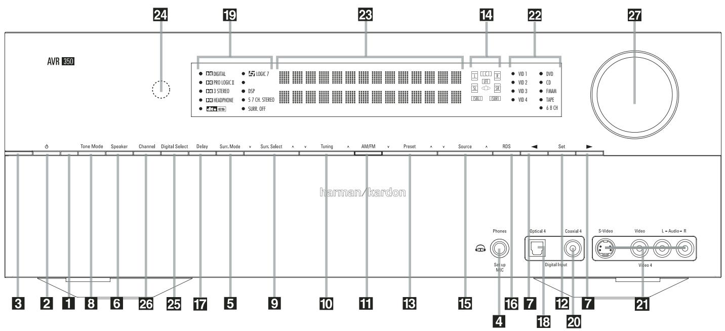
1 Main Power Switch
2 System Power Control
3 Power Indicator
4 Headphone Jack
5 Surround Mode Group Selector
6 Speaker Select Button
7 Selector Buttons
8 Tone Mode
9 Surround Mode Selector
10 Tuning
1 Tuner Band Selector
12 Set Button
13 Preset Stations Selector
14 Speaker/Channel Input Indicator
15 Input Source Selector
16 RDS Select Button
Delay
18 Digital Optical 4 Input
19 Surround Mode Indicators
20 Digital Coax 4 Input
21 Video 4 input jacks
22 Input Indicators
23 Main Information Display
24 Remote Sensor Window
25 Digital Input Selector
26 Channel Select Button
Volume Control
1 Main Power Switch: Press this button to apply power to the AVR. When the switch is pressed in, the unit is placed in a Standby mode, as indicated by the orange LED 3. This button MUST be pressed in to operate the unit. To turn the unit off completely and prevent the use of the remote control, this switch should be pressed until it pops out from the front panel so that the word "OFF" may be read at the top of the switch.
NOTE: This switch is normally left in the "ON" position.
2 System Power Control: When the Main
Power Switch 1 is "ON," press this button to turn on the AVR; press it again to turn the unit off (to Standby). Note that the Power Indicator
3 will turn white when the unit is on.
3 Power Indicator: This LED will be illuminated in orange when the unit is in the Standby mode to signal that the unit is ready to be turned on. When the unit is in operation, the indicator will turn white.
4 Headphone Jack: This jack may be used to listen to the AVR's output through a pair of headphones. Be certain that the headphones have a standard 6.3 mm stereo phone plug. Note that the speakers will automatically be turned off when the headphones are connected.
When configuring your system using EzSet/EQ, the calibration microphone should be plugged into this jack using the supplied adaptor that converts the small mini- plug at the end of the microphone's cord to a 1/4'' plug.
5 Surround Mode Group Selector: Press this button to select the top-level group of surround modes. Each press of the button will select a major mode grouping in the following order:
Dolby Modes DTS Digital Modes DSP Modes Stereo Modes Logic 7 Modes
Once the button is pressed so that the name of the desired surround mode group appears in the Main Information Display 28, press the Surround Mode Selector 9 to cycle through the individual modes available. For example, press this button to select Dolby modes, and then press the Surround Mode Selector 9 to choose from the various mode options.
6 Speaker Select Button: Press this button to begin the process of selecting the speaker positions that are used in your listening room. (See page 31 for more information on setup and configuration.)
7 Selector Buttons: When you are establishing the AVR's configuration settings, use these buttons to select from the choices available, as shown in the Main Information Display 23.
8 Tone Mode: Pressing this button enables o disables the Balance, Bass and Treble tone controls. When the button is pressed so that the words TONE IN appear in the Main Information Display 23, the settings of the Bass and Treble controls and of the Balance control will affect the output signals. When the button is pressed so that the words T ONE OUT appear in the Main Information Display 28, the output signal will be "flat, without any balance, bass or treble alteration.
9 Surround Mode Selector: Press this button to select from among the available surround mode options for the mode group selected. The specific modes will vary based on the number of speakers available, the mode group and if the input source is digital or analog. For example, press the Surround Mode Group Selector 5 to select a mode grouping such as Dolby or Logic 7, and then press this button to see the mode choices available. For more information on mode selection, see page 40.
10 Tuning Selector: Press the left side of the button to tune lower frequency stations and the right side of the button to tune higher frequency stations. When a station with a strong signal is reached, MANUAL TUNED or AUTO TUNED will appear in the Main Information Display (see page 51 for more information on tuning stations).
1 Tuner Band Selector: Pressing this button will automatically switch the AVR to the Tuner mode. Pressing it again will switch between the AM and FM frequency bands, holding it pressed for some seconds will switch between stereo and mono receiving and between automatic and manual tuning mode (See page 51 for more information on the tuner).
12 Set Button: When making choices during the setup and configuration process, press this button to enter the desired setting as shown in the Main Information Display 23 into the AVR's memory.
Preset Stations Selector: Press this button to scroll up or down through the list of stations that have been entered into the preset memory (See page 51 for more information on tuner programming).
14 Speaker/Channel Input Indicators: These indicators are multipurpose, indicating either the speaker type selected for each channel or the incoming data-signal configuration. The left, center, right, right surround and left surround speaker indicators are composed of three boxes, while the subwoofer is a single box. The center box lights when a "Small" speaker is selected, and the two outer boxes light when "Large" speakers are selected. When none of the boxes are lit for the center, surround or subwoofer channels, no speaker has been selected for that position. (See page 31 for more information on configuring speakers.) The letters inside each of the center boxes display active input channels. For standard analog inputs, only the L and R will light, indicating a stereo input. When a digital source is playing, the indicators will light to display the channels being received at the digital input. When the letters flash, the digital input has been interrupted. (See page 44 for more information on the Channel Indicators).
NOTE: When you have reassigned the surround back speakers to the remote zone using the MULTIROOM SETUP menu, the boxes that indicate the presence of the surround back speakers will automatically disappear, reflecting the fact that the main listening area is now configured for 5.1-channel operation. (See page 47 for more information on reassigning the surround back speakers for multiroom use.)
15 Input Source Selector: Press this button to change the input by scrolling through the list of input sources.
16 RDS Select Button: Press this button to display the various messages that are part of the RDS data system of the AVR's tuner. (See page 52 for more information on RDS).
17 Delay: Press this button to begin the sequence of steps required to enter delay time settings (See page 34 for more information on delay times).
18 Digital Optical 4 Input: Connect the optical digital audio output of an audio or video product to this jack. When the Input is not in use, be certain to keep the plastic cap installed to avoid dust contamination that might degrade future performance.
19 Surround Mode Indicators: The current selected mode or function will appear as one of these indicators. Note that when the unit is turned on, the entire list of available modes will light briefly, and then revert to normal operation with only the active mode indicator illuminated.
20 Digital Coax 4 Input: This jack is normally used for connection to the output of portable digital audio devices, video game consoles or other products that have a coax digital jack.
Video 4 Input Jacks: These audio/video jacks may be used for temporary connection to video games or portable audio/video products such as camcorders and portable audio players.
22 Input indicators: The current selected mode or function will appear as one of these indicators. Note that when the unit is turned on, the entire list of available modes will light briefly, and then revert to normal operation with only the active mode indicator illuminated.
23 Main Information Display: This display delivers messages and status indications to help you operate the receiver.
24 Remote Sensor Window: The sensor behind this window receives infrared signals from the remote control. Aim the remote at this area and do not block or cover it unless an external remote sensor is installed.
Note: When bridge /DMP has been selected as the input source, no Input Indicator 22 will light. DMP/THE BRIDGE IS CONNECTED will scroll across the Upper Display Line 23, unless you have retitled the source name, in which case that name will appear. See page 24 for more information on input tilting.
25 Digital Input Selector: When playing a source that has a digital output, press this button to select between the Optical 22 and Coaxial
Digital inputs. (See pages 24 and 41 for more information on digital audio).
26 Channel Select Button: Press this button to begin the process of trimming the channel output levels using an external audio source. (For more information on output level trim adjustment, see page 46).
27 Volume Control: Turn this knob clockwise to increase the volume, counterclockwise to decrease the volume. If the AVR is muted, adjusting volume control will automatically release the unit from the silenced condition.
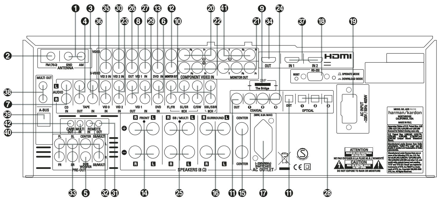
1 AM Antenna
FM Antenna
3 Tape Inputs
4 Tape Outputs
Subwoofer Output
DVD Audio Inputs
CD Inputs
3 Video 1 Audio Outputs
9 *DMP Connector
10 8-Channel Direct Inputs
Digital Audio Outputs
12 Video Monitor Outputs
DVD Video Inputs
14 Front Speaker Outputs
15 Center Speaker Outputs
NOTE: To assist in making the correct connections for multichannel input/output and speaker connections, all connection jacks and terminals have been color coded in conformance with the latest CEA standards as follows:
Front Left: White
Front Right: Red
Center: Green
Surround Left: Blue
Surround Right: Gray
Surround Back Left: Brown
Surround Back Right: Tan
Subwoofer (LFE): Purple
Digital Audio: Orange
Composite Video: Yellow
Component Video "Y": Green
Component Video "Pr": Red
Component Video "Pb": Blue
16 Surround Speaker Outputs
Switched AC Accessory Outlet
18 RS-232 Serial Port
19 AC Power Cord
20 Video 2 Component Video Inputs
21 Component Video Outputs
Video 1 Component Video Inputs
Video 2 Audio Inputs
Coaxial Digital Inputs
25 Surround Back/Multiroom Speaker Outputs
26 Video 1 Video Outputs
Video 1 Video Inputs
Optical Digital Inputs
29 Video 1 Audio Inputs
30 Video 2 Video Inputs
1 AM Antenna: Connect the AM loop antenna supplied with the receiver to these terminals. If an external AM antenna is used, make connections to the AM and GND terminals in accordance with the instructions supplied with the antenna.
FM Antenna: Connect the supplied indoor or an optional external FM antenna to this terminal.
3 Tape Inputs: Connect these jacks to the PLAY/OUT jacks of an audio recorder.
4 Tape Outputs: Connect these jacks to the RECORD/INPUT jacks of an audio recorder.
Subwoofer Output: Connect this jack to the line-level input of a powered subwoofer. If an external subwoofer amplifier is used, connect this jack to the subwoofer amplifier input.
DVD Audio Inputs: Connect these jacks to the analog audio jacks on a DVD or other audio or video source.
Remote IR Output
Remote IR Input
Preamp Outputs
34 HDMI Output
Video 3 Video Inputs
36 Video 3 Audio Inputs
37 HDMI Inputs
38 Multiroom Outputs
A-BUS Connector
40 Multiroom IR Input
DVD/Video 3 Component Video Inputs
Remote IR Carrier Output
CD Inputs: Connect these jacks to the analog output of a compact disc player or CD changer or any other audio source.
3 Video 1 Audio Outputs: Connect these jacks to the RECORD/INPUT audio jacks on a VCR or any other Audio recorder.
*Bridge Digital Media Player (DMP)
Connector: With the AVR 350 turned off, connect one end of the optional Harman Kardon Bridge to this proprietary connector, and the other to your compatible Apple iPod. When the Digital Media Player source is selected, you may view your iPod's control and navigation messages on your video display (if one is connected to one of the Video Monitor Outputs 2), and in the Upper and Lower Display Lines 28. You may navigate the iPod and select tracks for playback using the / / Buttons
14 15 37, the Set Button 16 and Transport Controls 26 on your AVR remote. See page 45 for more information.
10 8-Channel Direct Inputs: These jacks are used for connection to source devices such as DVD-Audio, Blu-ray, HD-DVD or SACD players with discrete analog outputs. Depending on the source device in use, all eight jacks may be used, though in many cases only connections to the front left/right, center, surround left/right and LFE (subwoofer input) jacks will be used for standard 5.1 audio signals.
Digital Audio Outputs: Connect these jacks to the matching digital input connector on a digital recorder such as a CD-R or MiniDisc recorder.
Video Monitor Outputs: Connect this jack to the composite and/or S-Video input of a TV monitor or video projector to view the on-screen menus and the output of any standard Video or S-Video source selected by the receiver's video switcher.
DVD Video Inputs: Connect these jacks to the composite or S-Video output jacks on a DVD player or other video source.
14 Front Speaker Outputs: Connect these outputs to the matching + or - terminals on your left and right speakers. In conformance with the new CEA color code specification, the White terminal is the positive, or "+" terminal that should be connected to the red (+) terminal on Front Left speaker with the older color coding, while the Red terminal is the positive, or "+" terminal that should be connected to the red (+) terminal on Front Right speaker. Connect the black (-) terminals on the AVR to the black (-) terminals on the speakers. See page 17 for more information on speaker polarity.
15 Center Speaker Outputs: Connect these outputs to the matching + and - terminals on your center channel speaker. In conformance with the new CEA color code specification, the Green Terminal is the positive, or "+" terminal that should be connected to the red (+) terminal on speakers with the older color coding. Connect the black (-) terminal on the AVR to the black negative (-) terminal on your speaker. (See page 17 for more information on speaker polarity.)
16 Surround Speaker Outputs: Connect these outputs to the matching + and - terminals on your surround channel speakers. In conformance with the new CEA color code specification, the Blue terminal is the positive, or "+" terminal that should be connected to the red (+) terminal on the Surround Left speaker with older color coding, while the Gray terminal should be connected to the red (+) terminal on the Surround Right speaker with the older color coding. Connect the black (-) terminal on the AVR to the matching black negative (-) terminals for each surround speaker. (See page 17 for more information on speaker polarity.)
Switched AC Accessory Outlet: This outlet may be used to power any device that you wish to have turn on when the AVR is turned on with the System Power Control switch 2.
RS-232 Serial Port: This specialized connector may be used with your personal computer in case Harman Kardon offers a software upgrade for the receiver at some time in the future. Leave the Mode switch popped out in the Operate position, unless the AVR 350 is being upgraded. The Reset switch is used only during the upgrade process.
19 AC Power Cord: Connect the AC plug to an unswitched AC wall output.
20 Video 2 Component Video Inputs:
Connect the Y/Pr/Pb component video outputs of an HDTV Set-top convertor, satellite receiver, or other video source device with component video outputs to these jacks. The factory default is for these jacks to be a linked to the Video 1 input, but you may change the setting at any time through the INPUT SETUP menu. See page 24 for more information on configuring the component video inputs.
Monitor Component Video Outputs:
Connect these outputs to the component video inputs of a video projector or monitor. When a source connected to one of the three Component Video Inputs 20241 is selected the signal will be sent to these jacks.
Video 1 Component Video Inputs:
Connect the Y/Pr/Pb component video outputs of a DVD player to these jacks. The factory default is for these jacks to be a linked to the DVD input, but you may change the setting at any time through the INPUT SETUP menu. See page 24 for more information on configuring the component video inputs.
Note: All component inputs/outputs can be used for RGB signals too, in the same way as described for the Y/Pr/Pb signals, then connected to the jacks with the corresponding color. RGB connection is not possible if the source outputs a separate sync signal (see page 18).
Video 2 Audio Inputs: Connect these jacks to the PLAY/OUT audio jacks on a second VCR or other audio or video source.
Surround Back/Multiroom Speaker
Coaxial Digital Inputs: Connect the coax digital output from a DVD player, HDTV receiver, the output of a compatible computer sound card playing MP3 files or streams, LD player, MD player or CD player to these jacks. The signal may be either a Dolby Digital signal, DTS signal, a 2 channel MPEG 1 signal, or a standard PCM digital source. Do not connect the RF digital output of an LD player to these jacks.
Outputs: These speaker terminals are normally used to power the surround back left/surround back right speakers in a 7.1 channel system. However, they may also be used to power the speakers in a second zone, which will receive the output selected for a multiroom system. To change the output fed to these terminals from the default of the Surround Back speakers to the Multiroom Output, you must change a setting in the MULTIROOM MENU of the OSD system. See page 47 for more information on configuring this speaker output. In normal surround system use, the brown and black terminals are the surround back left channel positive (+) and negative (-) connections and the tan and black terminals are the surround back right positive (+) and negative (-) terminals. For multiroom use, connect the brown and black SBL terminals to the red and black connections on the left remote zone speaker and connect the tan and black SBR terminals to the red and black terminals on the right remote zone speaker.
Video 1 Video Outputs: Connect these jacks to the RECORD/INPUT composite or S-Video jack on a VCR.
Video 1 Video Inputs: Connect these jacks to the PLAY/OUT composite or S-Video jacks on a TV or other video source.
Optical Digital Inputs: Connect the optical digital output from a DVD player, HDTV receiver, the output of a compatible computer sound card playing MP3 files or streams, LD player, MD player or CD player to these jacks. The signal may be either a Dolby Digital signal, a DTS signal, a 2 channel MPEG 1 signal, or a standard PCM digital source.
29 Video 1 Audio Inputs: Connect these jacks to the PLAY/OUT audio jacks on a TV or other audio or video source.
Video 2 Video Inputs: Connect these jacks to the PLAY/OUT composite or S-Video jacks on a second VCR or other video source.
Remote IR Output: This connection permits the IR sensor in the receiver to serve other remote controlled devices. Connect this jack to the "IR IN" jack on Harman Kardon or other compatible equipment.
Remote IR Input: If the AVR's front-panel IR sensor is blocked due to cabinet doors or other obstructions, an external IR sensor may be used. Connect the output of the sensor to this jack.
Preamp Outputs: Connect these jacks to an optional, external power amplifier for applications where higher power is desired.
34 HDMI Output: Connect this jack to the HDMI input on a compatible HDMI-equipped video display.
Video 3 Video Inputs: Connect these jacks to the PLAY/OUT composite or S-Video jacks on any video source.
Video 3 Audio Inputs: Connect these jacks to the PLAY/OUT audio jacks on any audio or video source.
HDMI Inputs: Connect the HDMI output of video sources such as a DVD player, set-top box or HDTV tuner to either of these jacks.
Multiroom Outputs: Connect these jacks to an optional audio power amplifier to listen to the source selected by the multiroom system in a remote room.
39 A-BUS Connector: Connect this jack to an optional A-BUS-certified remote room keypad or amplifier to extend the multiroom capabilities of your AVR. See page 21 for more information on A-BUS.
40 Multiroom IR Input: Connect the output of an IR sensor in a remote room to this jack to operate the AVR's multiroom control system.
Video 3 Component Video Inputs: These inputs may be used with any source device equipped with analog Y/Pr/Pb or RGB component video outputs. The factory default is for these jacks to be a linked to the Video 2 input, but you may change the setting at any time through the INPUT SETUP menu. See page 24 for more information on configuring the component video inputs.
Remote IR Carrier Output: The output of this jack is the full signal received at the Remote Sensor Window 24 or input through the Remote IR Input 2 including the carrier frequency that is removed from signals at the Remote IR Output 1. Use this output to extend IR remote signals to the input of compatible products by direct connection or through the use of optional, external IR "blasters". If you are in doubt as to which of the two IR Output jacks to use, we recommend that you consult with your dealer or installer, or check with the manufacturer of the external equipment you wish to control.
With the AVR's powerful processor, you may connect up to two HDMI-equipped source devices to the HDMI inputs using a single-cable connection, while benefiting from superior digital audio and video performance. However, if your video display is not HDMI-compatible, you will need to connect the source device to one of the other source inputs, selecting a coaxial or optical digital audio input and analog video input. See the Connections and Installation sections for more information.
If your video display has an HDMI input, but some of your sources have only analog video outputs, you may still rely on just the HDMI video connection to your display; the AVR will automatically transcode analog video signals to the HDMI format.
NOTE ON VIDEO CONNECTIONs: When connecting a video source product such as a VCR, DVD player, satellite receiver, cable set-top box, personal video recorder or video game to the AVR 350, you may use either a composite or S-video connection, but not both.
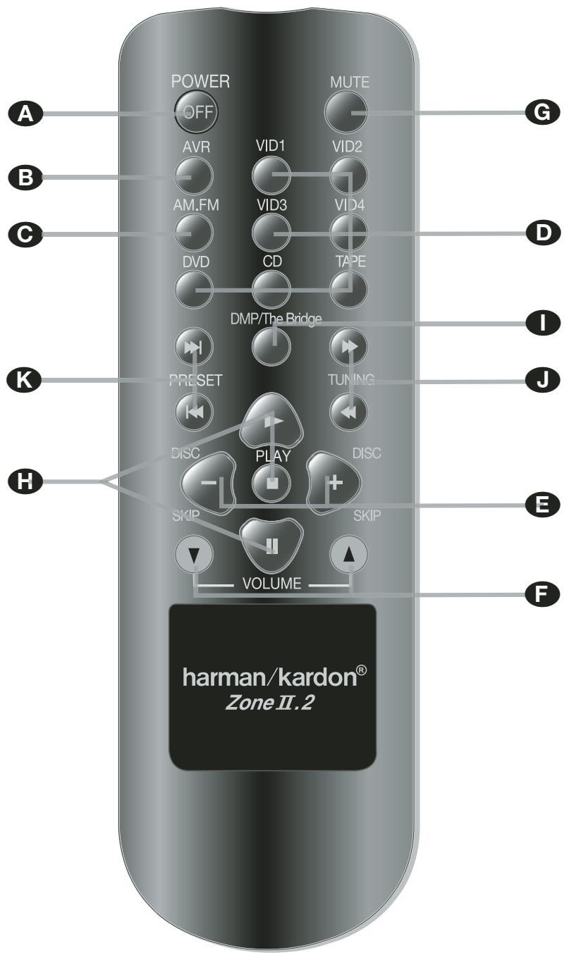
Power Off Button
IR Transmitter Window
3 Program Indicator
4 Power On Button
Input Selectors
6 AVR Selector
AM/FM Tuner Select
6-Channel/8-Channel Direct Input
Test Button
10 Sleep Button
11 Surround Mode Selector
12 Night Mode
13 Channel Select Button
14 ▲/▼ Buttons
15 Button
16 Set Button
17 Digital Select
18 Numeric Keys
19 Tuner Mode
20 Direct Button
21 Tuning Up/Down
2 OSD Button
23 Dolby Mode Select Button
DTS Digital Mode Selector
Logic 7 Mode Select Button
26 Transport Controls
27 Multiroom
28 Skip Up/Down Buttons
9 Stereo Mode Select Button
30 DTS Neo:6 Mode Select
31 Macro Buttons
32 RDS Selector Button
3 Preset Up/Down
34 Clear Button
35 Memory Button
36 Delay/Prev. Ch.
37▶Button
38 Speaker Select
39 Mute
40 Volume Up/Down
41 Bridge DMP Selector
42 TV/Video Selector
43 Dim Button
44 Learn Button
45 Light Button
46 Tone Mode
NOTE: The function names shown here are each button's feature when used with the AVR. Most buttons have additional functions when used with other devices. See page 58-59 for a list of these functions.

IMPORTANT NOTE: The AVR 350's remote may be programmed to control up to seven devices, including the AVR. Before using the remote, it is important to remember to press the Input
Selector button ⑤ that corresponds to the unit you wish to operate. In addition, the AVR's remote is shipped from the factory to operate the AVR and most Harman Kardon CD or DVD players and cassette decks. The remote is also capable of operating a wide variety of other products using the control codes that are part of the remote. Before using the remote with other products, follow the instructions on pages 53-55 to program the proper codes for the products in your system.
It is also important to remember that many of the buttons on the remote take on different functions, depending on the product selected using the Input Selector Button 5. The descriptions shown here primarily detail the functions of the remote when it is used to operate the AVR. (See page 58-59 for information about alternate functions for the remote's buttons.)
Power Off Button: Press this button to place the AVR or a selected device unit in the Standby mode.
IR Transmitter Window: Point this window towards the AVR when pressing buttons on the remote to make certain that infrared commands are properly received.
3 Program Indicator: This three-color indicator is used to guide you through the process of programming the remote. (See page 53 for information on programming the remote.)
4 Power On Button: Press this button to turn on the power to a device selected by pressing one of the Input Selectors (except Tape).
Input Selectors: Pressing one of these buttons will perform three actions at the same time. First, if the AVR is not turned on, this will power up the unit. Next, it will select the source shown on the button as the input to the AVR. Finally, it will change the remote control so that it controls the device selected.
The buttons labeled DVD, TAPE and HDMI 1 are each used to select either of two input sources:
- The first press of the DVD Button selects the component connected to the DVD inputs. A second press of this button selects the component connected to the CD inputs.
- The first press of the button labeled TAPE selects Tape as the input. A second press of this button selects the The Bridge as an input.
- The first press of the HDMI 1 button selects the device that is connected to the HDMI 1 jack. A second press selects the device connected to the HDMI 2 jack.
After pressing one of these buttons you must press the AVR Selector button ⑥ again to operate the AVR's functions with the remote.
AVR Selector: Pressing this button will switch the remote so that it will operate the AVR's functions. If the AVR is in the Standby mode, it will also turn the AVR on.
AM/FM Tuner Select: Press this button to select the AVR's tuner as the listening choice. Pressing this button when the tuner is in use will select between the AM and FM bands.
6-Channel/8 Channel Direct Input: Press this button to select the device connected to the 6-Channel Direct Inputs or the 8-Channel Direct Inputs (the input available will depend on the selection 5.1 or 6.1/7.1 made in the surround mode setting, see page 40 for more information).
Test Tone: Press this button to begin the sequence used to calibrate the AVR's output levels. (See page 35 for more information on calibrating the AVR).
10 Sleep Button: Press this button to place the unit in the Sleep mode. After the time shown in the display, the AVR will automatically go into the Standby mode. Each press of the button changes the time until turn-off in the following order:
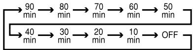
Hold the button pressed for two seconds to turn off the Sleep mode setting.
Note that this button is also used to change channels on your TV, VCR and Sat receiver when the appropriate source is selected, using the device Input Selectors 5.
11 Surround Mode Selector: Press this button to select any of the HALL, THEATER surround modes. Note that depending on the type of input, some modes are not always available. (See page 37-38 for more information about surround modes.) Note that this button is also used to tune channels on your TV, VCR and Sat receiver when the appropriate source is selected using the device Input Selector 5.
Night Mode: Press this button to activate the Night mode. This mode is available only with Dolby Digital encoded sources, and it preserves dialog (center channel) intelligibility at low volume levels (See page 27 for more information).
13 Channel Select Button: This button is used to start the process of setting the AVR's output levels with an external source. Once this button is pressed, use the / buttons 14 to select the channel being adjusted, then press the Set button 16, followed by the / buttons 14 again, to change the level setting. (See page 46 for more information.)
14 ▲/▼ Buttons: These multipurpose buttons are used to change or scroll through items in the on-screen menus or on the front panel or to make configuration settings such as digital inputs or delay timing. When changing a setting, first press the button for the function or setting to be changed (e.g., press the Digital Select Button 17 to change a digital input) and then press one of these buttons to scroll through the list of options or to increase or decrease a setting. The sections in this manual describing the individual features and functions contain specific information on using these buttons for each application.
When the AVR remote is being programmed for the codes of another device, these buttons are also used in the "Auto Search" process (See page 53 for more information on programming the remote.)
15 Button: This button is used to change the menu selection or setting during some of the setup procedures for the AVR.
Set Button: This button is used to enter settings into the AVR's memory. It is also used in the setup procedures for delay time, speaker configuration and channel output level adjustment.
17 Digital Select: Press this button to assign one of the digital inputs 24231820 to a source. (See page 41 for more information on using digital inputs.)
18 Numeric Keys: These buttons serve as a ten-button numeric keypad to enter tuner preset positions. They are also used to select channel numbers when TV, VCR or Sat receiver has been selected on the remote, or to select track numbers on a CD, DVD or LD player, depending on how the remote has been programmed.
Tuner Mode: Press this button when the timer is in use to select between automatic tuning and manual tuning. When the button is pressed so M AN U A L appears in the Main Information Display 23, pressing the Tuning buttons 21 10 will move the frequency up or down in single-step increments. When the FM band is in use and A U T 0 appears in the Main Information Display 23, pressing this button will change to monaural reception making even week stations audible. (See page 51 for more information.)
20 Direct Button: Press this button when the tuner is in use to start the sequence for direct entry of a station's frequency. After pressing the button simply press the proper Numeric Keys 13 to select a station (See page 51 for more information on the tuner).
21 Tuning Up/Down: When the tuner is in use, these buttons will tune up or down through the selected frequency band. If the Tuner Mode button 19 has been pressed or the Band button 11 on the front panel was held pressed so that A U T O appears in the Main Information Display 28, pressing either of the buttons will cause the tuner to seek the next station with acceptable signal strength for quality reception. When the MANUAL appears in the Main Information Display 28, pressing these buttons will tune stations in single-step increments. (See page 51 for more information.)
2 OSD Button: Press this button to activate the On Screen Display (OSD) system used to set up or adjust the AVR's parameters.
Dolby Mode Selector: This button is used to select one of the available Dolby Surround processing modes. Each press of this button will select one of the Dolby Pro Logic II modes, Dolby 3 Stereo or Dolby Digital. Note that the Dolby Digital mode is only available with a digital input selected and the other modes only as long as a Dolby Digital source is not playing (except Pro Logic II with Dolby Digital 2.0 recordings, see page 37-38). See page 37 for the available Dolby surround mode options.
DTS Digital Mode Selector: When a DTS source is in use the AVR will select the appropriate mode automatically and no other mode will be available. Pressing this button will display the mode currently selected by the AVR's decoder, depending on the surround material played and the speaker setting. When a DTS source is not in use, this button has no function. (See page 37 for the available DTS options.)
Logic 7 Selector: Press this button to select one of the available Logic 7 surround modes. (See page 37-38 for the available Logic 7 options.)
26 Transport Control Buttons: These buttons do not have any functions for the AVR, but they may be programmed for the forward/reverse play operation of a wide variety of CD or DVD players, and audio or video-cassette recorders. (See page 53 for more information on programming the remote.)
27 Multi-Room: Press this button to activate the Multiroom system or to begin the process of changing the input or volume level for the second zone. (See page 47 for more information on the Multiroom system.)
23 Skip Up/Down Buttons: These buttons do not have a direct function with the AVR, but when used with a compatibly programmed CD or DVD player/changer they will change the tracks on the disc currently being played.
29 Stereo Mode Selector: Press this button to select a stereo playback mode. When the button is pressed so that SURROUND OFF appears in the Main Information Display 23, with only the Surr Off Surround Mode Indicator 19 lit, the AVR will operate in a bypass mode with true fully analog, two-channel left/right stereo mode with no surround processing or bass management as opposed to other modes where digital processing is used. When the button is pressed so that SURROUND OFF appears in the Main Information Display 28, with both the DSP and Surr Off Surround Mode Indicators 19 lit, you may enjoy a two-channel presentation of the sound along with the benefits of bass management. When the button is pressed so that 5 CH STEREO or 7 CH STEREO appears, the stereo signal is routed to all five speakers, if installed. (See page 28 for more information on stereo playback modes).
DTS Neo:6 Mode Selector: Pressing this selector button cycles the AVR through the various DTS Neo:6 modes, which extract a five-, six- or seven-channel surround field from two-channel program material (from PCM source or analog input signal). The first press selects the last DTS Neo:6 surround mode that was in use, and each subsequent press selects the next mode.
31 Macro Buttons: Press these buttons to store or recall a "Macro", which is a pre-programmed sequence of commands stored in the remote. (See page 55 for more information on storing and recalling macros).
RDS Select Button: Press this button to display the various messages that are part of the RDS data system of the AVR's tuner. (See page 52 for more information on RDS).
Preset Up/Down: When the tuner is in use, press these buttons to scroll through the stations programmed into the AVR's memory. When CD or DVD is selected using the Input Selector button 5, these buttons may function as Slow Fwd/Rev (DVD) or ^ 串 +10 (CD, CDR).
34 Clear Button: Press this button to clear incorrect entries when using the remote to directly enter a radio station's frequency.
35 Memory Button: Press this button to enter a radio station into the AVR's preset memory. Two underline indicators will flash at the right side of the Main Information Display 28, you then have five seconds to enter a preset memory location using the Numeric Keys 18. (See page 51 for more information).
35 Delay/Prev Ch.: Press this button to begin the process for setting the delay times used by the AVR when processing surround sound. After pressing this button, the delay times are entered by pressing the Set button 16 and then using the / buttons 14 to change the setting. Press the Set button again to complete the process. (See page 34 for more information).
37 > Button: Press this button to change a setting or selection when configuring many of the AVR's settings.
33 Speaker Select: Press this button to begin the process of configuring the AVR's Bass Management System for use with the type of speakers used in your system. Once the button has been pressed, use the / buttons 14 to select the channel you wish to set up. Press the Set Button 16 and then select the speaker type (Large, Small or None) appropriate with the speaker in use. (See page 31 for more information).
39 Mute: Press this button to momentarily silence the AVR or TV set being controlled, depending on which device has been selected. When the AVR remote is being programmed to operate another device, this button is pressed with the Input Selector button 5 to begin the programming process. (See page 53 for more information on programming the remote).
40 Volume Up/Down: Press these buttons to raise or lower the system volume.
41 "Bridge" Digital Media Player (DMP) Selector: When Harman Kardon's "Bridge" (optional) is connected to "Bridge" Digital Media Player (DMP) Connector 9 and a compatible Apple iPod is docked in "Bridge", pressing this selector will select the iPod as the audio source input device for the AVR 350. In addition, if a video display is connected to one of the Video Monitor Outputs 2, the iPod's messages will appear on screen, and in the
Upper and Lower Display Lines 23. The / / / Buttons 14 15 37, the Set Button 16 and the Transport Controls 26 may be used to navigate the iPod and to operate many functions. See page 45, and the manuals for The Bridge and your iPod for more information.
42 TV/Video Button: This button does not have a direct function on the AVR, but when used with a compatibly programmed VCR, DVD or satellite receiver that has a "TV/Video" function, pressing this button will switch between the output of the player or receiver and the external video input to that player. Consult the Owner's Manual for your specific player or receiver for the details of how it implements this function.
NOTE: With the press of any remote button the Input Selector button 5 6 associated with the bottom pressed will briefly flash red to confirm the transmission of the command, as long as there is a function for that button with the device selected (see function list on pages 58-59).
Dim Button: Press this button to activate the Dimmer function, which reduces the brightness of the front-panel display, or turns it off entirely. The first press of the button shows the default state. Press the button again to change the display to reduce the brightness by 50% , and press it again within five seconds and the main display will go completely dark. Note that this setting is temporary; regardless of any changes, the display will always return to full brightness when the AVR is turned on. The white illumination of the Power Indicator 3 will always remain at full brightness regardless of the setting to remind you that the AVR is still turned on.
44 Learn Button: The remote control is capable of "learning" individual IR codes from the original remote control that came with your TV or other device that is connected to any of the source inputs. (See page 54 for more information).
45 Light Button: Press this button to illuminate the buttons on the remote control. Press it again to turn the backlight off, or wait for five seconds after the last button press for the light to turn off on its own.
46 Tone Mode: Pressing this button enables or disables the Balance, Bass and Treble tone controls. When the button is pressed so that the words TONE IN appear in the Main Information Display 23, the settings of the Bass and Treble controls and of the Balance control will affect the output signals. When the button is pressed so that the words T ONE OUT appear in the Main Information
Display 23, the output signal will be "flat", without any balance, bass or treble alteration.
A Power Off
B AVR Selector
AM/FM Tuner Select
D Input Selectors
E Disc Skip
Volume Up/Down
Mute
Transport Controls
Bridge /DMP Selector
Tuning Up/Down
K Preset Up/Down
NOTE: The Zone II.2 remote may be used in either the same room where the AVR is located, or it may be used in a separate room with an optional infrared sensor that is connected to the AVR's Multi IR input jack 40. When it is used in the same room as the AVR, it will control the functions of the AVR or any compatible Harman Kardon products in that room. When it is used in a separate room via a sensor connected to the Multi IR Jack 40, the buttons for power, input source, volume and mute will control the source and volume for the second zone, as connected to the Multi Out Jacks 38. (See page 47 for complete information on using the Multiroom system.)
The Zone II remote may be used in either the same room where the AVR is located, or it may be used in a separate room with an optional infrared sensor that is connected to the AVR's Multi IR input jack 40 or an A-BUS device.
Power Off: When used in the room where the AVR is located, press this button to place the unit in Standby. When it is used in a remote room with a sensor that is connected to the Multi IR jack 40, this button turns the Multi-Room system off.
AVR Selector: Press this button to turn on the AVR. The input in use when the unit was last on will be selected.
AM/FM Tuner Select: Press this button to select the Tuner as the input to the Multiroom system. Press it again to change between the AM and FM bands.
Input Selectors: When the AVR is off, press one of these buttons to turn the unit on and to select a specific input. When the unit is already in use, pressing one of these buttons will change the input.
Disc Skip: Press this button to change discs on compatible Harman Kardon CD or DVD changers.
Volume Up/Down: When used in the room where the AVR is located, press this button to raise or lower the volume in that room. When it is used in a remote room with a sensor that is connected to the Multi IR Jack 40, this button will raise or lower the volume in the remote room.
Mute: When used in the room where the AVR is located, press this button to temporarily silence the unit. When it is used in a remote room with a sensor that is connected to the Multi IR Jack 40, this button will temporarily silence the feed to the remote room only. Press the button again to return to the previous volume level.
Important Note: No matter in which room the Zone II remote is used, as with the main remote it is important to remember to press the Input Selector button D that corresponds to the unit you wish to operate before you change the device to be controlled.
Transport Control Buttons: These buttons do not have any functions for the AVR, but they are programmed for the forward/ reverse play operation of a wide variety of Harman Kardon CD or DVD players, and audio or video- cassette recorders.
1 ^th Bridge Digital Media Player (DMP) Selector: When Harman Kardon's ^th Bridge (optional) is connected to ^th Bridge Digital Media Player (DMP) Connector 9 and a compatible Apple ^th iPod is docked in the Bridge, pressing this selector will select the iPod as the audio source input device for the AVR 350. In addition, if a video display is connected to one of the Video Monitor Outputs 2, the iPod's messages will appear on screen, and in the Upper and Lower Display Lines 23. The / / Buttons 14 15 37, the Set Button 16 and the Transport Controls 26 may be used to navigate the iPod and to operate many functions. See page 45, and the manuals for The Bridge and your iPod for more information.
Tuning Up/Down: When the tuner is in use, these buttons will tune up or down through the selected frequency band. If the Tuner Mode button 19 has been pressed or the Band button 11 on the front panel was held pressed so that A U T O appears in the Main Information Display 28, pressing either of the buttons will cause the tuner to seek the next station with acceptable signal strength for quality reception. When the MANUAL appears in the Main Information Display 28, pressing these buttons will tune stations in single-step increments. (See page 51 for more information.)
Preset Up/Down: When the tuner is in use, press these buttons to scroll through the stations programmed into the AVR's memory. When CD or DVD is selected using the Input Selector button 5, these buttons may function as Slow Fwd/Rev (DVD) or ^ 串 + 1 0 ^ 串 (CD, CDR).
After unpacking the unit, and placing it on a solid surface capable of supporting its weight, you will need to make the connections to your audio and video equipment.
Audio Equipment Connections
There are two formats for audio connections: digital and analog. Digital audio signals are of higher quality, and are required for listening to sources encoded with digital surround modes, such as Dolby Digital and DTS. There are three types of digital audio connections: HDMI, coaxial and optical. Any one type of digital audio connection may be used for each source device, but never more than one for the same source. However, it's okay to make both analog and digital audio connections at the same time to the same source.
Since the AVR is capable of processing the audio and video portions of an HDMI signal, if your video display device has an HDMI input, you may make a single HDMI connection from your source device (such as a DVD player) to the AVR. In that case no separate digital audio connection is required.
We recommend that you use high-quality interconnect cables when making connections to source equipment and recorders to preserve the integrity of the signals.
When making connections to audio source equipment or speakers it is always a good practice to unplug the unit from the AC wall outlet. This prevents any possibility of accidentally sending audio or transient signals to the speakers that may damage them.
HDMI Connections
HDMI™ is the abbreviation for High-Definition Multimedia Interface, which is quickly becoming the standard connection point between advanced video/audio source products and displays, particularly for high-definition video signals. HDMI is a digital connection, eliminating the need to convert signals back and forth from digital to analog to deliver a higher quality signal when used with digital sources. The signals carried on HDMI may, but do not always, include audio, offering the possibility of a complete one-wire connection from a source to the AVR. However, it is important to note that there are a number of different versions of the HDMI standard in use. Before connecting any HDMI products to your AVR, it is helpful to find out in advance their level of HDMI connectivity.
Some source or display components in your system may use DVI (Digital Video Interface) for digital video connections. DVI carries the same digital video signals as HDMI but uses a larger connector and does not transport audio or control signals. In most cases, you may mix and match DVI and HDMI digital video connections by using optional connector adapters. Note, however, that some DVI-equipped video displays are not compatible with the HDCP copy protection coding that is increasingly carried with signals connected via HDMI. If you have an HDMI source and a DVI-equipped display, you may occasionally be unable to view a program if the display does not include HDCP. This is not the fault of the AVR or your source; it simply indicates that the video display is not compatible.
HDMI Input Connections
The different "Version" levels of HDMI define which type of audio signals it is compatible with. Based on the lowest level of HDMI among your sources, the connections to the AVR should be made as follows:
-
HDMI 1.0 sources carry digital video and multichannel or 2-channel PCM audio signals only. Connect the HDMI output of a 1.0 source to either of the HDMI Inputs on the AVR. If the product is a DVD-Audio player or other source that has multichannel analog audio outputs, connect them to the 8-Channel Direct Inputs With an HDMI 1.0 source, particularly a DVD player, make certain that the menus in the source device are set to "Bitstream Out" or "Original" so that 5.1 digital audio is available. If you find that 5.1 Dolby Digital or DTS audio is not available on the HDMI connection, it will be necessary to make an additional connection between the source and the AVR 350 to either the Coaxial 2420 or Optical 2818 Digital Inputs.
-
HDMI 1.1 sources carry the multichannel digital audio output from DVD-Audio players in addition to the digital video. If you have an HDMI 1.1-equipped product, the only connection needed for listening in the main room is from the HDMI output of the source to either of the HDMI Inputs on the AVR. If the player has SACD, HD-DVD or Blu-ray capability, you will need to connect the analog outputs of the source to the 8-Channel Direct Inputs
-
HDMI 1.2 (and higher) sources should be connected as shown above for HDMI 1.1, except that a separate analog connection is not needed for SACD players.
In addition, the AVR will convert analog video signals to the HDMI format, upscaling to high-definition 720p resolution. Source signals with 1080i or 1080p resolution are passed through to your display at their original high-quality resolution, depending on your display's capabilities. You may view the AVR's own on-screen display menus using the HDMI output.
HDMI cable runs are usually limited to about 3 meters. The AVR incorporates a repeater, which allows an additional 3 meters of cable between the source device and the video display.
If your video display or source device is not HDMI-capable, you will need to use either a coaxial or optical digital audio connection and one of the analog video connections (composite, S- or component video), if available, as described in the next paragraphs.
- It is not possible to feed an analog composite or S-video signal to a recorder or the AVR's multizone system when an HDMI input is in use. If an HDMI-equipped source also has analog audio and video outputs, connect them to the Video 2 or Video 3 Video ③ and Audio 23 on the AVR.
- In some instances, HDMI-equipped sources will not permit more than one video output at a time, and thus you cannot use the same source in the main listening room and with the recorder or remote zone at the same time. This is not a fault of the AVR, but rather a function of the content protection systems that are part of the HDMI standard.
HDMI Output Connections
Connect the HDMI Output to an HDMI input on your video display. Thanks to the AVR 350's video processing system, all video input signals are converted to an HDMI output, so only one connection is required between the AVR and your display.
Analog and Digital Input Connections
- Connect the analog output of a CD player to the CD inputs ⑦.
NOTE: When the CD player has both fixed and variable audio outputs it is best to use the fixed output unless you find that the input to the receiver is so low that the sound is noisy, or so high that the signal is distorted. -
Connect the analog Play/Out jacks of a cassette deck, MD, CD-R or other audio recorder to the Tape Input jacks ③. Connect the analog Record/In jacks on the recorder to the Tape Output jacks ④ on the AVR.
-
Connect the digital output of any digital sources such as a CD or DVD changer or player, advanced video game, a digital satellite receiver, HDTV tuner or digital cable set-top box or the output of a compatible computer sound card to the Optical and Coaxial Digital Inputs 282418 20.
We recommend connecting the coaxial digital audio output of your DVD player to the Coax 1 Digital Audio Input, since that digital input is assigned to the DVD source by default.
The Video 2/Cable/Sat source defaults to the Optical 1 Digital Audio Input. If your cable television set-top box or satellite receiver is equipped with an optical digital audio output, we recommend that you connect it to this input to obtain the benefits of higher-quality digital audio (such as PCM, Dolby Digital 2.0 or Dolby Digital 5.1 signals when broadcast by your cable or satellite provider).
NOTE: If you wish for your digital source device to be available for use by the multiroom system, you will need to connect its analog audio outputs to the appropriate inputs on the AVR 350, as the multiroom system is not capable of distributing digital signals to the remote zone.
- Connect the Coaxial or Optical Digital
Outputs 1 on the rear panel of the AVR to the matching digital input connections on a CD-R or MiniDisc recorder.
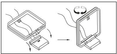
- Assemble the AM Loop Antenna supplied with the unit as shown below. Connect it to the AM and GND screw terminals 1.
-
Connect the supplied FM antenna to the FM (75 ohm) connection ②. The FM antenna may be an external roof antenna, an inside powered or wire lead antenna or a connection from a cable system. Note that if the antenna or connection uses 300-ohm twin-lead cable, you should use a 300-ohm-to-75-ohm adapter to make the connection.
-
With the AVR 350 turned off, connect the optional Harman Kardon The Bridge to The Bridge . Digital Media Player (DMP) Connector
Your compatible Apple® iPod® may be docked in _TM^Bridge when you wish to use it as your audio source device.
- Connect the front, center and surround speaker outputs 14151625 to the respective speakers.
To assure that all the audio signals are carried to your speakers without loss of clarity or resolution, we suggest that you use high-quality speaker cable. Many brands of cable are available and the choice of cable may be influenced by the distance between your speakers and the receiver, the type of speakers you use, personal preferences and other factors. Your dealer or installer is a valuable resource to consult in selecting the proper cable.
Regardless of the brand of cable selected, we recommend that you use a cable constructed of fine, multistrand copper with an area greater than 2mm^2
Cable with an area of 1.5mm^2 may be used for short runs of less than 4m . We do not recommend that you use cables with an area less than 1mm^2 due to the power loss and degradation in performance that will occur.
Cables that are run inside walls should have the appropriate markings to indicate listing with any appropriate testing agency standards. Questions about running cables inside walls should be referred to your installer or a licensed electrician who is familiar with the applicable local building codes in your area.
When connecting wires to the speakers, be certain to observe proper polarity. Note that the positive (+) terminal of each speaker connection now carries a specific color code as noted on page 8. However, most speakers will still use a red terminal for the positive (+) connection. Connect the "negative" or "black" wire to the same terminal on both the receiver and the speaker.
NOTE: While most speaker manufacturers adhere to an industry convention of using black terminals for negative and red ones for positive, some manufacturers may vary from this configuration. To assure proper phase and optimal performance, consult the identification plate on your speaker or the speaker's manual to verify polarity. If you do not know the polarity of your speaker, ask your dealer for advice before proceeding, or consult the speaker's manufacturer.
We also recommend that the length of cable used to connect speaker pairs be identical. For example, use the same length piece of cable to connect the front-left and front-right or surround-left and surround-right speakers, even if the speakers are a different distance from the AVR.
-
Connections to a subwoofer are normally made via a line level audio connection from the Subwoofer Output ⑤ to the line-level input of a subwoofer with a built-in amplifier. When a passive subwoofer is used, the connection first goes to a power amplifier, which will be connected to one or more subwoofer speakers. If you are using a powered subwoofer that does not have line-level input connections, follow the instructions furnished with the speaker for connection information.
-
If an external multi-channel audio source with 5.1 outputs such as an external digital processor/decoder, DVD-Audio, SACD, Blu-ray or HD-DVD player is used, connect the outputs of that device to the 8-Channel Direct Inputs (10).
Video Equipment Connections
Video equipment is connected in the same manner as audio components. Again, the use of high-quality interconnect cables is recommended to preserve signal quality. To ensure best video performance S-Video sources should be connected to the AVR only with their S-Video In/Outputs, not with their composite video connectors too.
If you have already connected a source device to one of the HDMI inputs as explained in the Audio Equipment section, then you have automatically made a video connection at the same time, as the HDMI signal includes both digital audio and video components.
If your video display or source device is not HDMI-capable, you will need to use one of the analog video connections (composite, S- or component video), if available, as described below.
If the source device is not capable of transmitting its digital audio signal through the HDMI connection, then use one of the coaxial or optical digital audio inputs for the source.
If a multichannel analog audio connection is required for certain lossless formats (e.g. DVD-Audio, SACD, HD-DVD or Blu-ray Disc), you may make both connections. To listen to the multichannel disc, first select the HDMI source input, then select the 6-/8-channel analog audio inputs, and the AVR will retain the last video source you selected.
- Connect a VCR's audio and video Play/Out jacks to the Video 2 In jacks ② ①0 on the rear panel. The Audio and Video Record/In jacks on the VCR should be connected to the Video 1 Out jacks 26 8 on the AVR.
- Although any video device may be connected to these jacks, we recommend connecting your TV to the Audio 1 Audio/Video Input Jacks 2927 so that you may take advantage of the fact that the remote control is preprogrammed with TV product codes for the Video 1 device. For the same reason, we recommend connecting your video recorder, cable TV converter or satellite receiver to the Video 2 Audio/Video Input Jacks 2330 .
- Connect the analog audio and video outputs of a DVD or laser disc player to the DVD jacks 6 18.
- Connect the digital audio outputs of a CD, MD or DVD player, satellite receiver, cable box or HDTV converter to the appropriate Optical or Coaxial Digital Inputs 28241820. Remember that the DVD source defaults to the Coaxial 1 Digital Input 24. All other sources default to their analog inputs, although any source may be assigned to any digital audio input on the receiver.
NOTE: When connecting a device such as a digital cable box or other set-top tuner product with a digital audio output, we recommend that you connect both the digital and analog outputs of the product to your AVR. The audio input polling feature of the AVR will then be able to make certain that you have a constant audio feed, since it will automatically switch the audio input to the analog jacks if the digital feed is interrupted or not available for a particular channel.
-
Connect the Composite and S-Video (if S-Video device is in use) Monitor Output ⑫ jacks on the receiver to the composite and S-Video input of your television monitor or video projector.
-
If your DVD player and monitor both have component video connections, connect the component outputs of the DVD player to the Video 1 Component Video Inputs ② . Note that even when component video connections are used the audio connections must still be made to either the analog DVD Audio Inputs ⑥ or any of the Optical or Coaxial Digital Input jacks 28 × 24 .
- If another component video device is available, connect it to the Video 2 or Video 3 Component Video Input jacks ② 41. The audio connections for this device should be made to either the Video 2 Input jacks ④ or any of the Optical or Coaxial Digital Input jacks ⑧ 24.
- If the component video inputs are used, connect the Component Video Output 2 to the component video inputs of your TV, projector or display device.
- If you have a camcorder, video game or other audio/video device that is connected to the AVR on a temporary, rather than permanent basis, connect the audio, video and digital audio outputs of that device to the Front Panel Inputs 182021. A device connected to the Video 4 jacks 21 is selected as the Video 4 input, and connected to the digital jacks 1820 it is selected as "Optical 3" or "Coaxial 3" input. (See page 24 for more information on input configuration.)
- When connecting the AVR 350 to a standard, analog video display that has standard composite and S-Video inputs only, component video inputs may not be used. In this case, connect the Video and S-Video Monitor Outputs to the matching composite and S-Video inputs on your video display, depending on which types of video are used by your source devices. If both types of video are used by different source devices, than both Video Monitor Outputs must be separately connected to your television.
Video Connection Notes:
- All component inputs/outputs can be used for RGB signals too, in the same way as described for the Y/Pr/Pb signals, then connected to the jacks with the corresponding color. But this is only correct as long as only the three RGB video signals are output by the video source, with a sync signal in the "G" signal only, without any sync signal output separately by the source.
SCART A/V Connections
For the connections described above your video device needs RCA (cinch) connectors or/and S-Video connectors for all Audio and Video signals: Any normal video device (Not SVHS or High 8) for only playback needs 3 RCA jacks, VCRs for record and playback even 6 RCA jacks. Any S-Video device (SVHS, High 8) needs 2 RCA (Audio) and 1 S-Video jack (Video), if it's a playback unit, or 4 RCA (Audio In/Out) and 2 S-Video (Video In/Out) jacks, if it's a recording VCR.
Many european video devices are equipped with RCA (Cinch) or S-Video jacks only partially, not for all audio and video in/outputs needed as described above, but with a so called Scart or Euro-AV connector (almost rectangular jack with 21 pins, see drawings on next page).
In that case the following Scart to Cinch adapters or cables are needed:
- Units for playback, such as satellite receivers, camcorders, DVD or LD players, need an adapter from Scart to 3 RCA plugs, see fig. 1 (normal video devices) or from Scart to 2 RCA+1 S-Video plugs, see fig. 4 (S-Video devices).
- HiFi VCRs need an adapter from Scart to 6 RCA plugs, see fig. 2 (normal video), or from Scart to 4 Audio+2S-Video jacks, see fig. 5 (S-Video VCR). Read carefully the instruction attached to the adapter to find which of the six plugs is used for the record signal to the VCR (connect with the AVR's Out jacks) and for the playback signal from the VCR (connect with the AVR's In jacks). Do not disconnect Audio and Video signals. Don't hesitate to consult your dealer, if you are uncertain.
- If you use only normal video devices the TV monitor needs an adapter from 3 RCA plugs to Scart (fig. 3) only. If also S-Video devices are used an adapter from 2 RCA+1S-Video plugs to Scart is needed additionally (fig. 6), connected to the SCART input on your TV that is provided for S-Video.
Note that only the video plugs (the "yellow" cinch plug in fig. 3 and the S-Video plug in fig. 6) must be connected to the TV Monitor Output 2, and the volume on the TV must be reduced to minimum.
Important Note for Adapter Cables:
If the cinch connectors of the adapter you'll use are labeled, connect the Audio and Video "In" plugs with the corresponding Audio and Video "In" jacks on the AVR (and with a VCR connect the "Out" plugs to the "Out" jacks on the VCR). Note that with some adapter types it may be just turned around: If no signal is audible/visible when the VCR is playing connect the "Out" plugs to the "In" jacks on the AVR and turned around. If the adapter plugs are not labeled in that way, pay attention to the signal flow directions as shown in the diagrams above and in the instruction attached to the adapter. If uncertain, don't hesitate to consult your dealer.
Important Notes for S-Video connections:
Only the S-Video In/Out of S-Video devices must be connected to the AVR, NOT both, normal video and S-Video In/Outputs (except the TV, see item below).
When both connections are made, only the S-Video signal will be viewed on the screen.
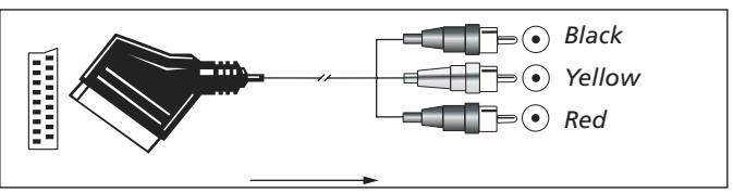
Figure 1: SCART/Cinch-Adapter for playback; signal flow: SCART Cinch
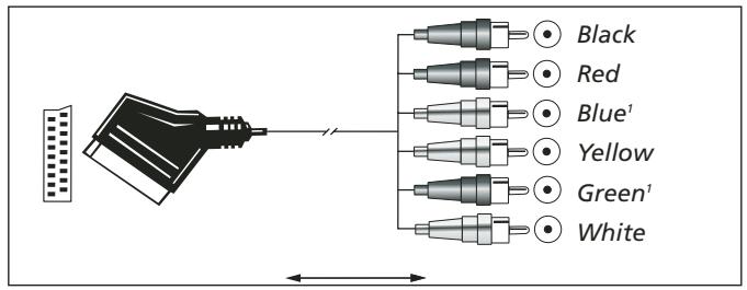
Figure 2: SCART/Cinch-Adapter for record and playback; signal flow: SCART Cinch
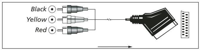
Figure 3: Cinch/SCART-Adapter for playback; signal flow: Cinch SCART
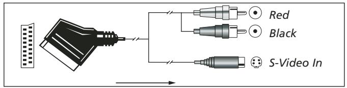
Figure 4: SCART/S-Video Adapter for playback; signal flow: SCART Cinch
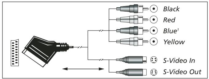
Figure 5: SCART/S-Video Adapter for record and playback; signal flow: SCART Cinch
Figure 6: SCART/S-Video Adapter for playback; signal flow: Cinch SCART
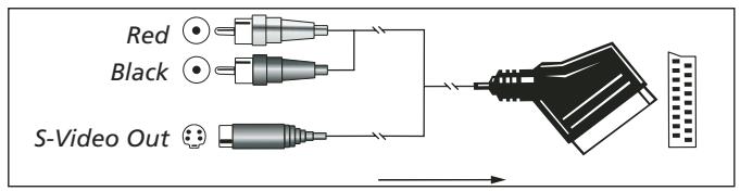
1 Also other colours possible, e.g. brown and grey.
Important Note for the Use of SCART-Cinch Adapters:
When video sources are connected to the TV directly with a SCART cable, specific control signals apart from Audio/Video signals will be fed to the TV. These specific signals are: With all video sources, the signal for automatic input selection that switches the TV automatically to the appropriate input as soon as the video source is started. And with DVD players, the signals automatically turning the TV to 4:3/16:9 format (with 16:9 TVs or with 4:3 TVs with selectable 16:9 format) and turning the RGB video decoder of the TV on or off, depending on the DVD player's setting. With any adapter cable, these control signals will be lost and the appropriate setting of the TV must be made manually.
Note for RGB signal with SCART:
If you use a unit providing RGB signals on a SCART output (as e.g. most DVD players do) and you want to use that RGB signal, this SCART output must be connected directly to your TV. Although the AVR can switch three-way video signals (like component signals Y/Pb/Pr), most TVs need separate sync signals for RGB (also with SCART) that cannot be switched and provided by the AVR.
RGB signals can be pathed through the AVR only when no separate sync signal is needed (see last "Video Connection Note" on page 15).
System and Power Connections
The AVR 350 is designed for flexible use with multiroom systems, external control components and power amplifiers.
Main Room Remote Control Extension
If the receiver is placed behind a solid or smoked glass cabinet door, the obstruction may prevent the remote sensor from receiving commands. In this event, the remote sensor of any Harman Kardon or other compatible device, not covered by the door, or an optional remote sensor may be used. Connect the Remote IR
Output of that device or the output of the remote sensor to the Remote IR Input jack 32.
If other components are also prevented from receiving remote commands, only one sensor is needed. Simply use this unit's sensor or a remote eye by running a connection from the Remote
IR Output jack ③ to the Remote IR Input jack on Harman Kardon or other compatible equipment.
Multiroom IR Link
The key to remote room operation is to link the remote room to the AVR's location with wire for an infrared receiver and speakers or an amplifier. The remote room IR receiver (this can be an optional IR receiver or any other remotable Harman Kardon device in the remote room with IR sensor integrated) should be connected to the AVR via standard coaxial cable. Connect the
Remote IR Output of the device or of the optional sensor with the Multiroom IR Input jack 40 on the AVR's rear panel.
If other Harman Kardon compatible source equipment is part of the main room installation, the Remote IR Output jack on the rear panel should be connected to the IR IN jack on that source device. This will enable the remote room location to control source equipment functions.
When a remote IR sensor is used to control non-Harman Kardon source equipment, we recommend that you make a direct connection or use an optional, external IR "blaster" connected to the Remote IR Carrier Output Jack. If you are in doubt as to which IR Output jack to use for the equipment in your system, contact your dealer or installer, or the manufacturer's support site and ask whether the unit to be controlled uses "full carrier" or "stripped" carrier IR commands. When "full carrier commands" are used, make the connection to the Remote IR
Carrier Output Jack 42. Otherwise, make the connection to the Remote IR Output Jack 51 as noted above.
NOTE: All remotely controlled components must be linked together in a "daisy chain". Connect the IR OUT jack of one unit to the IR IN of the next to establish this chain.
Multiroom Audio Connections
Depending on your system's requirement and distance from the AVR to the remote room, three options are available for audio connection:
Option 1: Use high-quality, shielded audio interconnect phono cable from the AVR's location to the remote room. In the remote room, connect the interconnect cable to a stereo power amplifier. The amplifier will be connected to the room's speakers. At the AVR, plug the audio interconnect cables into the Multiroom
Output Jacks 38 on the AVR's rear panel.
Option 2: Place the amplifier that will provide power to the remote location speakers in the same room as the AVR, and connect the
Multiroom Output jacks on the rear panel of the AVR to the audio input of the remote room amplifier. Use the appropriate speaker wire to connect the optional power amplifier to the remote speakers. High-quality wire of at least 2.5mm^2 is recommended for long multiroom connections.
Option 3: Taking advantage of the AVR's built-in seven-channel amplifier, it is possible to use two of the amplifier channels to power speakers in the remote room. When using this option you will not be able to use the full 7.1-channel capabilities of the AVR in the main listening room, but you will be able to add another listening room without additional external power amplifiers. To use the internal amplifiers to power a remote zone, connect the speakers for the remote room location to the Surround
Back/Multiroom Speaker Outputs 25
Before using the remote room you will need to configure the amplifiers for surround operation by changing a setting in the Multiroom menu, following the instructions shown on page 47.
NOTE: For all options, you may connect an optional IR sensor (Harman Kardon He 1000) in the remote room to the AVR via an appropriate cable. Connect the sensor's cable to the
Multiroom IR Input 40 on the AVR and use the Zone II remote to control the room volume. Alternatively, you may install an optional volume control between the output of the amplifiers and the speakers.
NOTE: The AVR 350's multiroom system is only capable of distributing analog audio sources to the remote zone. Therefore, when connecting your digital audio equipment (e.g. CD or DVD players) as described on page 17, make sure to use both analog and digital audio connections to ensure that the devices will be available to the multiroom system.
A-BUS Installation Connections
The AVR is among the very few receivers available today that offers built-in A-BUS Ready® operation. When used with an optional A-BUS keypad or control module, you have all the benefits of remote zone operation without the need for an external power amplifier.
To use the AVR with an approved A-BUS product, simply connect the keypad or module that is in the remote room to the AVR using standard "Category 5" wiring that is properly rated for the inwall use specific to the installation.
Terminate the wiring at the receiver end to a standard RJ-45 jack in compliance with the instructions furnished with the A-BUS module.
You may connect a single A-BUS module to the AVR 350 with no further equipment needed. If you wish to connect more than one A-BUS module, an optional, external A-BUS hub may be used to provide that capability.
No further installation or adjustment is needed, as the A-BUS connector on the AVR routes the signals in and out of the keypad to their proper destination for power, signal source and control. The output fed to the A-BUS jack is determined by the AVR's multiroom system, and the menus may be used as is.
AC Power Connections
This unit is equipped with one accessory AC outlet. It may be used to power accessory devices, but should not be used with high-current draw equipment such as power amplifiers. The total power draw to the Switched Outlet ⑦ should not exceed 50 watts.
The Switched 17 outlet will receive power only when the unit is on completely. This is recommended for devices that have no power switch or a mechanical power switch that may be left in the "ON" position.
NOTE: Many audio and video products go into a Standby mode when they are used with switched outlets, and cannot be fully turned on using the outlet alone without a remote control command.
The AVR draws significantly more current than other household devices such as computers that use removable power cords. For that reason, it is important that only the cord supplied with the unit (or a direct replacement of identical capacity) be used.
Once the power cord is connected, you are almost ready to enjoy the AVR 350's incredible power and fidelity!
Speaker Selection
No matter which type or brand of speakers is used, the same model or brand of speaker should be used for the front-left, center and front-right speakers. This creates a seamless front soundstage and eliminates the possibility of distracting sonic disturbances that occur when a sound moves across mismatched front-channel speakers.
Speaker Placement
The placement of speakers in a multichannel home-theater system can have a noticeable impact on the quality of sound reproduced.
Depending on the type of center-channel speaker in use and your viewing device, place the center speaker either directly above or below your TV, or in the center behind a perforated front-projection screen.
Once the center-channel speaker is installed, position the left-front and right-front speakers so that they are as far away from one another as the center-channel speaker is from the preferred listening position. Ideally, the front-channel speakers should be placed so that their tweeters are no more than 60~cm above or below the tweeter in the center-channel speaker.
They should also be at least 0.5 meter from your TV set unless the speakers are magnetically shielded to avoid colourings on the TV screen. Note that most speakers are not shielded, even with complete surround sets only the Center speaker may be.
Depending on the specifics of your room acoustics and the type of speakers in use, you may find that imaging is improved by moving the front-left and front-right speakers slightly forward of the center-channel speaker. If possible, adjust all front loudspeakers so that they are aimed at ear height when you are seated in the listening position.
Using these guidelines, you'll find that it takes some experimentation to find the correct location for the front speakers in your particular installation. Don't be afraid to move things around until the system sounds correct. Optimize your speakers so that audio transitions across the front of the room sound smooth.
When the AVR is used in 5.1-channel operation, the preferred location for surround speakers is on the side walls of the room, at or slightly behind the listening position. In a 6.1-channel system, a back surround speaker is required, ideally placed at the center of the room's rear wall, pointing directly towards the front center channel speaker. The center of the speaker should face you (see below).
In a 7.1-channel system, both side surround and back surround speakers are required. The center of the speaker should face you (see below).
Rear surround speakers are required when a full 7.1-channel system is installed, and they may also be used in 5.1 channel mode as an alternative mounting position when it is not practical to place the main surround speakers at the sides of the room. Speakers may be placed on a rear wall, behind the listening position. As with the side speakers, the center of the rear surrounds should face you. The speakers should be no more than 2 meters behind the rear of the seating area.
It is appropriate to configure the AVR 350 for either 5.1- or 7.1-channel operation, but not for 6.1 channels. When 6.1-channel program material or a 6.1-channel processing mode is in use, material for the surround back channel will be outputted simultaneously through both the Surround Back Left and Right Speaker
Outputs 25. Connecting only one loudspeaker to these speaker terminals will not only deprive you of the benefits of 7.1-channel surround modes, such as Logic 7, but will also interfere with the functioning of EzSet/EQ speaker setup and calibration, as described on page 28. It may also put undesirable strain on the surround back amplifier circuits and power supplies.
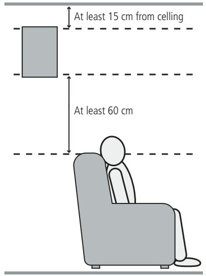
A) Front Channel Speaker Installation with Direct-View TV Sets or Rear-Screen Projectors.
Subwoofoers produce largely nondirectional sound, so they may be placed almost anywhere in a room. Actual placement should be based on room size and shape and the type of subwoofer used. One method of finding the optimal location for a subwoofer is to begin by placing it in the front of the room, about 15cm from a wall, or near the front corner of the room. Another method is to temporarily place the subwoofer in the spot where you will normally sit, and then walk around the room until you find a spot where the subwoofer sounds best. Place the subwoofer in that spot. You should also follow the instructions of the subwoofer's manufacturer, or you may wish to experiment with the best location for a subwoofer in your listening room.
Once the speakers have been placed in the room and connected, the remaining steps are to program the system configuration memories.
Although it is necessary to assign input/output settings and surround mode choices manually, we recommend that you take advantage of the power and precision of EzSet/EQ to automatically select and enter the settings for all other audio parameters. This will not only save you time; it will ensure that your room is calibrated and equalized with an accuracy not possible when these settings are made manually. You are now ready to power up the AVR 350 to begin these final adjustments.
First Turn On
You are now ready to power up the AVR to begin these final adjustments.
- Plug the Power Cable 19 into an unswitched AC outlet.
- Press the Main Power Switch 1 in until it latches and the word "OFF" on the top of the switch disappears inside the front panel. Note that the Power Indicator 3 will turn orange, indicating that the unit is in the Standby mode.
- Remove the protective plastic film from the main front-panel lens. If left in place, the film may affect the performance of your remote control.
- Install the three supplied AAA batteries in the remote as shown. Be certain to follow the (+) and (-) polarity indicators that are on the top of the battery compartment.

- Turn the AVR on either by pressing the System Power Control 2 or the Input Source Selector 15 on the front panel, or via the remote by pressing the Power On Button 4, AVR Selector 6 or any of the Input Selectors 5 7 on the remote. The Power Indicator 3 will turn white to confirm that the unit is on, and the Main Information Display 23 will also light up.
NOTE: After pressing one of the Input Selector buttons 5 to turn the unit on, press the AVR Selector 6 to have the remote control the AVR functions.
Using the On-Screen Display
When making the following adjustments, you may find them easier to make via the unit's on-screen display system. These easy-to-read displays give you a clear picture of the current status of the unit and facilitate speaker, delay, input or digital selection you are making.
To view the on-screen displays, make certain you have made a connection from either the HDMI Output 34 or the Video Monitor Out jack 12 on the rear panel to the HDMI, component, composite or S-Video input of your TV or projector. In order to view the AVR's displays, the correct video input must be selected on your video display.
IMPORTANT NOTE: When viewing the on-screen menus using a CRT-based projector, plasma display or any direct-view CRT monitor or television, it is important that they not be left on the screen for an extended period of time. As with any video display, but particularly with projectors, constant display of a static image such as these menus or video game images may cause the image to be permanently "burned into" the CRT. This type of damage is not covered by the AVR warranty and may not be covered by the projector TV set's warranty.
The AVR has two on-screen display modes, "Semi-OSD" and "Full-OSD." When making configuration adjustments, it is recommended that the Full-OSD mode be used. This will place a complete status report or option listing on the screen, making it easier to view the available options and make the settings on the screen. The Semi-OSD mode uses one-line displays only.
Note that when the full OSD system is in use, the menu selections are not shown in the Information Display 23. When the full OSD menu system is used, O S D O N will appear in the Main Information Display 23 to remind you that a video display must be used.
When the semi-OSD system is used in conjunction with the discrete configuration buttons, the on screen display will show a single line of text with the current menu selection. That selection will also be shown in the Main Information Display 28.
The full OSD system can always be turned on or off by pressing the OSD button 22. When this button is pressed the MASTER menu (Figure 1) will appear, and adjustments are made from the individual menus. Note that the menus will remain on the screen for 20 seconds after the latest action was made on the screen menu, then they will "time-out" and disappear from the screen. The time-out may be increased to as much as 50 seconds by going to the SYSTEM SETUP menu, and changing the item titled FULL OSD TIME OUT.
The semi-OSD system is also available as a system default, although it may be turned off by using the SYSTEM SETUP menu. (See page 49). With the semi-OSD system, you may make adjustments directly, by pressing the buttons on the front panel or remote control for the specific parameter to be adjusted. For example, to change the digital input for any of the sources, press the Digital Select Button 2517 and then any of the Selector buttons 7 or 14 on the front panel or remote.
System Setup
The AVR 350 features an advanced memory system that enables you to establish different configurations for, digital input, surround mode, for each input source. This flexibility enables you to custom tailor the way in which you listen to each source and have the AVR memorize them. This means, for example, that you may associate different surround modes and analog or digital inputs with different sources. Once these settings are made, they will automatically be recalled whenever you select that input.
However, we recommend that the first time you use the AVR, you take advantage of the simplicity of configuring the system using the EzSet/EQ process, which takes the guesswork out of speaker size and delay settings, and balances the speaker output levels to tailor the AVR's sound presentation to your specific system and room. Before beginning the EzSet/EQ procedure, there are a few adjustments that need to be made to ensure accurate results.
The factory default settings for the AVR 350 have all inputs configured for an analog audio input except for the DVD input, where the Coaxial Digital Input 24 is the default and the Video 2 input, where the Optical Digital Audio Input 28 is the default. Once the DSP processing system is used for the first time for any input, the speaker settings will automatically default to "Small" at all positions with the subwoofer set to "Sub (LFE)" The default setting for the surround modes is Logic 7 Music, although Dolby Digital or DTS will automatically be selected as appropriate when a source with digital encoding is in use.
Before using the unit, you will probably want to change the settings for most inputs so that they are properly configured to reflect the use of digital or analog inputs and the surround mode associated with the input. Remember that since the AVR memorizes the settings for each input individually, you will need to make these adjustments for each input used. However, once they are made, further adjustment is only required when system components are changed.
To make this process as quick and as easy as possible, we suggest that you use the full-OSD system with the on-screen menus, and step through each input.
It is recommended that you record your settings for each input using the work-sheets in the appendix to this manual, in the event there is a power loss or if you need to reenter the settings for some other reason.
The OSD system consists of six main menus: Input Setup, Surround Setup, Speaker Setup, Multiroom Setup, Video Setup and System Setup. Navigation tabs for each menu appear on the left side of the screen. When you first press the OSD Button 22, the Input Setup menu will be visible (see Figure 1), since its tab is at the top of the screen. However, you must press the Set Button 16 to select the Input Setup menu so that you can make any necessary adjustments. If you wish to select another menu, use the
/ Buttons 14 to highlight the tab for the desired menu, and press the Set Button 16 to select it.
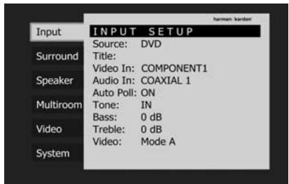
Figure 1
When you first select a menu, the first setting line will be highlighted (see Figure 2).

Figure 2
If you wish to change that setting, press the Set Button 16. Although the setting name will remain highlighted, the value will appear in blue type with arrows to the right, indicating that you may use the Buttons 15 to scroll through the available values. See Figure 3. When the desired value appears, press the Set Button 16 to select it.

Figure 3
Use the / Buttons 14 to navigate to other settings within the menu. When you have finished making all adjustments in that menu, press the Button 15 to return to the navigation tabs, and then use the / Buttons 14 to select the tab for another menu.
Input Setup
The first step in configuring the AVR is to select an input, i.e. to associate an analog or digital input with each input source in use, e.g. CD or DVD. Note that once an input is selected, all settings for the Digital Input, will "attach" themselves to that input and be stored in a nonvolatile memory. This means that once made, the selection of an input will automatically recall those settings. For that reason, the procedures described below must be repeated for each input source so that you have the opportunity to custom tailor each source to your specific listening requirements. However, once made they need not be changed again unless you need to alter a setting.
When using the full-OSD system to make the setup adjustments, press the OSD button 22 once so that the INPUT SETUP menu (Figure 2) will appear on the screen. Press the Set Button 16 once to highlight the Source-line. Press the Set Button 16 again, followed by the buttons 1537 until the desired input name appears in blue text. If the input will use the standard left/right analog inputs, no further adjustment is needed.
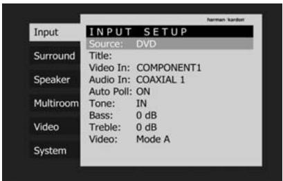
Figure 2
The AVR offers you the option of renaming each input (except tuner) as it appears in the on-screen and front panel messages. This is helpful if you have more than one VCR, if you wish to associate a specific product brand name with the input, or to simply enter any name that will help you to remember which source is being selected.
To change the input name, press the / Navigation Button 14 on the remote so that the Title-line is highlighted in blue. The screen shown in Figure 4 will appear. Use the Navigation Buttons 14 15 37 to highlight the desired letter (or other character), and press the Set Button 16 to add it to the new title, which will be displayed in the bar at the top of the screen. You may use the Navigation Buttons 14 15 37 to move the cursor within the new title. To add a space either move the cursor one character to the right as described above, or highlight the SPACE indicator on screen and press the Set Button 16.
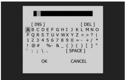
Figure 4
You may edit a title by inserting or deleting characters. To insert a new character between two existing characters, move the cursor to highlight the character to the right of the insertion pointing the bar at the top of the screen. Then highlight the INS indicator on screen and press the Set Button 16. You may now select a character to insert in the new space. Delete a character by moving the cursor to highlight the unwanted character in the bar at the top of the screen. Then highlight the DEL indicator on screen and press the Set Button 16.
When you have finished entering the new title, highlight the OK indicator and press the Set Button to return to the Input Setup menu. Although the Source Input name will remain the same in the Input Setup menu, the new title will appear in the semi-OSD displays and the front-panel display as appropriate.
NOTES:
- Only upper case letters are available for titles.
- Normally both the source input and the digital (or analog) audio input selection appear on the upper line of the semi-OSD and front-panel displays. When The Bridge source is selected, its status as CONNECTED or UNPLUGGED appears in place of the audio input selection. However, when a source input is retitled, the audio input selection (or status of The Bridge) no longer appear unless you press the Digital Input Selector 17 25 on the remote or front panel.
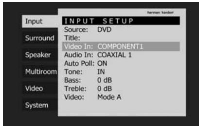
Figure 5
The Video In setting reflects the video input that is assigned to the source. The default assignment for all sources is COMPOSITE except as shown in the below table:
| Source Input | Default Video Input |
| DVD | COMPONENT 1 |
| VIDEO 1 | COMPONENT 2 |
| VIDEO 2 | COMPONENT 3 |
| HDMI 1 | HDMI 1 |
| HDMI 2 | HDMI 2 |
We recommend that you leave the setting for the HDMI sources as is. For the other sources, change this setting in the Video In line to reflect use of the Component 1, 2 or 3 Video Input as appropriate. If you used the composite or S-video input for any source, make sure this setting is COMPOSITE. (There is no separate selection for S-Video.)
NOTE: If your video display has an HDMI input, then you only need to connect the AVR's HDMI Output to the display. The AVR 350 transcodes analog source video signals from composite, S-video or component video to the HDMI format, and is also capable of upscaling the signal to match your display's capabilities.
If your display does not have an HDMI input, but does have component video inputs, again you only need to connect the AVR's Component Video Monitor Outputs 2 to the display. The AVR 350 transcodes composite and S-video signals to the component video format. Similarly, if your display's best-quality video input is S-video, you do not need to connect the Composite Video Monitor Output to the display; any composite video source signals will be converted to S-video format, and S-video signals may be converted to composite video format if your video display is not equipped with an S-video input.
By default, the analog audio inputs are assigned at the factory to all sources, with the following exceptions:
Source Input Default Digital Audio Input
DVD Coax 1
Video 2 Optical 1
HDMI1 Coax 2
HDMI2 Optical 2
If you used a digital audio connection for another source, you will need to change this setting on the Audio In line of the menu to assign the correct digital audio input to the source, even if you also connected the analog audio outputs of the source to the receiver.
Figure 6
To associate an analog or digital input with the input source currently selected at any time using the discrete function buttons, press the Digital Input Select Button 2517 on the front panel or the remote while the full-OSD is not in use. Within five seconds, make your input selection using the Selector buttons on the front panel 7 or the / 4 Buttons on the remote until the desired digital or analog input is shown in the Main Information Display 23 and in the lower third of the video display connected to the AVR. Press the Set Button 16 to enter the new input assignment.
Some digital video input sources, such as a cable box or HDTV set-top may change between analog and digital outputs, depending on which channel is in use. The AVR's Auto Polling feature allows you to avoid losing the audio feed when this happens by permitting both analog and digital connections to the same source on the AVR. Digital audio is the default, and the unit will automatically switch to the analog audio if the digital audio stream stops.
Figure 7
In cases where only a digital source is used, you may wish to disable the Auto Polling feature to prevent the AVR from trying to "find" an analog source when the digital source is paused. To turn Auto Polling off for any input, first make certain that the Auto Poll Line is highlighted in blue, and press the Set Button on the menu screen. Next, press the Navigation Button so that OFF is highlighted in blue text. Repeat the procedure at any time by highlighting ON to restore the Auto Polling feature.
The remaining lines in the Input Setup menu allows you to configure the tone controls. If you do not wish to change any of those settings at this time, proceed to the next menu screen.
Figure 8
The first line controls whether or not the bass/ treble tone controls are in the signal path. The normal default is for them to be in-line, but if you wish to remove them from the circuit for "flat" response, first make certain that the
Tone In line is highlighted in blue, and press
the Set Button 16, followed by the
Navigation Button 1537 so that OUT is highlighted in blue text.
If you wish to leave the tone controls in the signal path, the amount of boost or cut for bass and treble may be adjusted by pressing the
/ Navigation Button 14 so that the Bass - or Tre b1e line is highlighted in blue. Next, press the Set Button 16 followed by the / Navigation Button 1537 until the desired setting is shown.
The video mode setting is used only with a fully analog video path (composite, S-video or component video). It has no effect on HDMI sources and video displays. Due to the design of some analog video displays and the nature of the video standard, there may be timing issues with the AVR. If you observe some minor video instability when using the AVR's analog video outputs, try changing the Video Mode setting to Mode B. If you continue to observe problems, connect your source device's video output directly to the video display, or consider upgrading to an HDMI-capable display.
Surround Setup
The next step for that input is to set the surround mode you wish to use with that input. Since surround modes are a matter of personal taste, feel free to select any mode you wish -- you may change it later. The Surround Mode chart on page 37-38 may help you select the mode best suited to the input source selected. For example you may select Dolby Pro Logic II or Logic 7 for most analog inputs and Dolby Digital for inputs connected to digital sources. In the case of inputs such as a CD Player, Tape Deck or Tuner, you may wish to set the mode to Stereo, if that is your preferred listening mode for standard stereo sources, where it is unlikely that surround encoded material will be used. Alternatively, the 5 Channel Stereo or Logic 7 Music mode may also be a good choice for stereo-only source material.
It is easiest to complete the surround setup using the full-OSD on-screen menus. Use the
/ Buttons 14 to highlight the Surround tab, and press the Set Button 16 to access the SURROUND SETUP menu, as shown in Figure 9. With the
Surround Mode line highlighted, press the Set Button 16 to change the surround mode group. Use the Buttons 1537 to scroll through the options, and press the Set Button 16 when the desired mode group appears.
Navigate to the Mode line and follow the same procedure to select an individual mode.
Figure 9
Each of the option lines on this menu selects the surround mode category, and within each of those categories there will be a choice of the specific mode options. The choice of modes will vary according to the speaker configuration in your system.
When the Surr Back line of the SPEAKER SETUP menu (Figure 25) is set to NONE the AVR will be configured for 5.1-channel operation, and only the modes appropriate to a five-speaker system will appear.
When the Surr Back line of the SPEAKER SETUP menu (Figure 25) is set to SMALL or LARGE the AVR will be configured for 6.1/7.1-channel operation, and additional modes such as Dolby Digital EX and 7 STEREO or Logic 7 7.1 will appear. In addition, the modes DTS ES (Discrete) and DTS+NEO:6 (DTS ES Matrix) available in the AVR 350 will not appear unless a digital source is playing the correct bitstream.
In addition, some of the modes available in the AVR will not appear unless a digital source is selected and is playing the correct bitstream.
Remember that when you use only a single, surround back speaker, you will get the benefits of a 6.1/7.1 system, but with only one speaker installed at the back of the room. The mode indications will show 7.1 in some cases, but no additional adjustment is needed for 6.1 operation. Remember that the AVR will combine the left and right surround back channel information present in 7.1 modes such as Logic 7/7.1 and 7-channel stereo, outputting the information as a single surround back channel.
Note: When a Dolby Digital or DTS source is selected and playing, the AVR will select the appropriate surround mode automatically, no matter which surround mode was selected for that input as default.
On the Dolby Surround mode, the selection choices include Dolby Digital, Dolby Pro Logic II or Ilx Music, Dolby Pro Logic II or Ilx Cinema, Dolby Pro Logic II and Dolby 3 Stereo. The Dolby Digital EX and Dolby Pro Logic Ilx modes are only available when the system is set for 6.1/7.1 operation by configuring the Surround Back speakers to "Small" or "Large" as described on page 31. When a disc is playing that contains a special "flag" signal in the digital audio data stream, the EX mode will be selected automatically. It may also be selected using this menu or through the front panel or remote controls as shown on page 41. A complete explanation of these modes is found on Page 37-38. Note that when the Dolby Digital mode is selected there are additional settings available for the Night mode that are associated with the surround mode only, not with the input. That's why these settings must be made only once, not with each input in use. They are described later in the next main chapter.
When the Mode line is highlighted in blue, press the Set Button 16 and the Navigation Buttons 15 to select the desired Dolby surround mode, again remembering that the choice of available modes will vary with the type of program material being played and the number of speakers in your system configuratioin.
When Dolby Pro Logic II Music or Dolby Pro Logic IIx Music is selected as the listening mode, three special settings appear in the menu to tailor the sound field to your listening room environment and your individual taste and preferences.
-
Center Width: This setting adjusts the balance of the vocal information in the front sound-stage between the center and front left/right speakers. The lower settings spread the center channel sound more broadly into the left and right channels. A higher number (up to "7") produces a tighter center channel presentation.
-
Dimension: This setting alters the perceived depth of the surround field by creating a shallower presentation that appears to move sounds toward the front of the room, or a deeper presentation that appears to move the center of the sound field toward the back of the room. The setting of "O" is a neutral default, with the range of adjustment shown as "R-3" for a deeper, rear-oriented sound to "F-3" for a shallower, front-oriented sound.
-
Panorama: Switch this setting on or off to add an enveloping wrap-around presentation that increases the perception of sound along the sides of the room.
Figure 10
To change these parameters, press the / Navigation Buttons 14 while the Surround menu is on the screen until the line on the menu with the parameter you wish to change is highlighted in blue. Then, press the Set Button 16 and the Navigation Buttons 1537 to alter the setting to your taste.
Note that when the Dolby Digital mode is selected there are additional settings available for the Night mode that are associated with the surround mode only, not with the input. That's why these settings must be made only once, not with each input in use.
Night Mode Settings
The Night mode is a feature of Dolby Digital that uses special processing to preserve the dynamic range and full intelligibility of a movie sound track while reducing the peak level. This prevents abruptly loud transitions from disturbing others, without reducing the sonic impact of a digital source. Note that the Night mode is only available when the Dolby Digital surround mode is selected.
To adjust the Night mode setting from the menu press the OSD Button 22 so that the main menu appears. Then press the button 14 to highlight the Surround -tab and press Set 16 to access it. Press the Button 14 twice until the Night-line is highlighted in blue. (see figure 11).

Figure 11
To adjust the Night mode setting, first press the Set Button 16, followed by the Buttons 1537 to choose between the following settings.
OF F: When OFF is highlighted, the Night mode will not function.
MID: When MID is in the highlighted video, a mild compression will be applied.
MAX: When MAX is in the highlighted video, a more severe compression algorithm will be applied.
When you want to use the Night mode feature, we recommend that you select the MID setting as a starting point and change to the MAX setting later, if desired.
Note that the Night mode may be adjusted directly any time that Dolby Digital surround mode is selected by pressing the Night button 12. When the button is pressed, the words D-RANGE followed by the current setting (MID, MAX, OFF) will appear in the lower third of the video screen and in the Main Information Display 23. Press the / buttons 14 within five seconds to select the desired setting, then press Set 16 to confirm the setting.
The last option line in this menu is the setting to turn the unit's upsampling feature on or off. In normal use, this feature is turned off, which means that digital sources are processed at their native sample rate. For example, a 48kHz digital source will be processed at 48kHz. However, the AVR allows you to upsample the incoming 48kHz signals to 96kHz for added resolution.
Figure 12
To take advantage of this feature, press the Navigation Button 14 so that the Upsampling -line is highlighted in blue and press Set Button 16, followed by the Navigation Button 1537 so that ON is highlighted in reverse video. Note that this feature is only available for the Dolby Pro Logic II-Music, Dolby Pro Logic II-Movie, Dolby Pro Logic and Dolby 3 Stereo modes.
On the DTS menu, the selection choices made with the Buttons 1537 on the remote are determined by a combination of the type of DTS program material in use and whether the 5.1 or 6.1/7.1 speaker output configuration is in use.
When a DTS source is playing, the choice of modes for 7.1 systems will vary according to the type of program source (DTS Stereo, DTS 5.1, DTS-ES Matrix or DTS-ES Discrete). Press the
Buttons 1537 to scroll through the choices that are available for your system and the program in use.
With no source playing, or while an analog audio source is playing, you will only be able to view the DTS Neo:6 surround mode.
When the 5.1 configuration is in use the AVR will automatically select the 5.1 version of DTS processing when a DTS data stream is received. When the 6.1/7.1 mode is selected, the DTS-ES Discrete mode will automatically be activated when a DTS source with the ES Discrete "flag" is in use and the DTS-ES Matrix mode will be activated when an ES-Matrix encoded audio track is received. In both cases the appropriate surround mode will be indicated in the Main
Information Display 23 in the front panel display and on the screen. When a non-ES DTS disc is in use, when the 6.1/7.1 mode is chosen the unit automatically will select the DTS + NEO:6 mode to create a full eight-speaker surround mode. When a DTS 96/24 signal is detected, the AVR 350 defaults to the DTS surround mode, but reproduces the higher-resolution materials that are present due to the higher sampling rate automatically. See page 37-38 for a complete explanation of the DTS modes.
On the LOGIC 7 menu, the selection choices made with the Buttons 1537 on the remote are determined by whether the 5.1 or 6.1/7.1 speaker output configuration is in use. In either case, the selection of a Logic 7 mode enables Harman Kardon's exclusive Logic 7 processing to create fully enveloping, multi-channel surround from either two-channel Stereo or Matrix-encoded programming such as VHS cassettes, laserdiscs or television broadcasts produced with Dolby surround.
In the 5.1 configuration you may select the Logic 7/5.1 Music, Cinema or Enhanced modes. They work best with two-channel music, surround-encoded programs or standard two-channel programming of any type, respectively. When the 6.1/7.1 mode is selected, the Logic 7/7.1 Music or Cinema modes are available, but the output will be in a full eight-channel sound field. Note that the Logic 7 modes are not available when either Dolby Digital or DTS Digital soundtracks are in use.
On the DSP (SURR) menu, the selection choices made with the Buttons on the remote select one of the DSP surround modes that are designed for use with two-channel stereo programs to create a variety of sound field presentations. The choices available are 5.1 or 6.1 modes of Hall 1, Hall 2 and Theater. The Hall and Theater modes are designed for multi-channel installations. See pages 37-38 for a complete explanation of the DSP surround modes. Note that the Hall and Theater modes are not available when a Dolby Digital or DTS soundtrack is played.
On the STEREO menu, the selection choices made with the Buttons 1537 on the remote may either turn the surround processing off for a traditional two-channel stereo presentation, or select 5 CH Stereo or 7 CH Stereo depending on whether the 5.1 or 6.1/7.1 output is in use. The latter modes feed the stereophonic input signal to both front speakers, to the rear speakers and to both surround back speakers (if in use), while the monophonic signal parts are spread over all speakers, also the Center. See page 37-38 for a complete explanation of the 5 CH Stereo and 7 CH Stereo modes.
After the selections are made in the Dolby, DTS, Logic 7, DSP (Surround) or Stereo menus, press the Button 15 to go back to the main menu.
Configuring the Surround Off (Stereo) Modes
For superior reproduction of two-channel program materials, the AVR offers two Stereo modes: an analog Stereo-Direct mode that bypasses the digital signal processing circuitry for a completely analog signal path that preserves the purity of the original signal, and a digital mode that is capable of providing bass management for optimal distribution of the low frequencies between smaller speakers and a subwoofer.
Stereo-Direct (Bypass) Mode
When the analog Stereo-Direct mode is selected by pressing the Stereo Mode Selector 29 until SURROUND OFF appears in the Main Information Display 28 and the Surround Mode Indicator 19 for Surround Off is lit, the AVR will pass the analog source material directly through to the front left and right speakers, bypassing the digital processing circuitry.
In this mode, the front left and right speakers will automatically be configured as LARGE; it is not possible to configure these speakers as SMALL.
When the AVR is in the Stereo Bypass mode you may still configure the subwoofer output so that it is either turned off, with a full-range signal going to the front left/right speakers, or you may configure it so that the subwoofer feed is activated.
The factory default setting is to have the subwoofer turned off for this mode, but you may change that setting by following these steps:
- Press the Speaker Button 638.
- Press the Set Button 16 to activate the configuration menu.
- Press the / Buttons 14 on the remote or the Buttons 7 on the front panel to select the desired option. SUB NONE turns off the feed to the subwoofer, while SUB < L + R> turns it on.
- When the desired setting has been entered, press the Set Button 16 to return to normal operation.
Stereo-Digital Mode
When the Stereo-Direct (Bypass) mode is in use a full range signal is always sent to the front left/right speakers. By its nature, that option does not pass the signal through the AVR's digital signal processing, creating the requirement for full-range speakers. If your front speakers are bandwidth limited, "satellite"speakers, we recommend that you do NOT use the Bypass mode, but rather use the DSP SURROUND OFF mode for stereo listening.
To listen to programs in the two-channel stereo mode while taking advantage of the bass management system, press the Stereo Mode Selector 29 until SURROUND OFF appears in the Main Information Display 28 and the DSP and SURR - OFF Surround Mode Indicators 19 both light up. When only the SURR - OFF Surround Mode Indicators 19 is lit you are in the Stereo-Direct (Bypass) mode.
When this mode is in use, the front left/right speakers and subwoofer may be configured to meet the requirements of your specific speakers using the steps shown in the Speaker Setup section below.
Automated Speaker Setup Using EzSet/EQ
The AVR 350 is one of the first receivers in its class to offer automated speaker setup and system calibration. This process greatly simplifies the installation of your new receiver by using a series of test signals and the power of an advanced digital signal processing system to eliminate the need for manual adjustment of speaker "size", crossover, delay and output level settings, while adding the power of a multi-band parametric equalizer to smooth out any peculiarities in frequency response that may result from the characteristics of the listening room. With EzSet/EQ your new receiver even alerts you to errors in speaker connections that prevent a speaker from functioning.
With EzSet/EQ you are able to calibrate your system in a fraction of the time it would take to enter the settings manually, and with results that rival those achieved with expensive test equipment and time-consuming procedures. The end result is a system calibration profile that enables your new receiver to deliver the best possible sound, no matter what type of speakers you have or what the dimensions of your listening room are.
We recommend that you take advantage of the precision of EzSet/EQ to calibrate your system, but if desired you may also make any of the configuration settings manually, or trim the settings provided by EzSet/EQ by following the instructions on pages 31 through 34.
Figure 13
If you wish to configure your AVR manually, or if for some reason your EzSet/EQ microphone is unavailable, you may still do so by following the instructions on pages 31 through 34.
Step 1: EzSet/EQ requires that your listening room have as little background noise as possible to avoid interfering with the measurement of tones produced by your AVR during the setup procedure. Turn off all loud fans, air conditioners and other equipment, and try to avoid making any noise during the process.
Step 2: The EzSet/EQ microphone should be placed in either your usual listening position or, if there is a large seating area, the center of the room, at the listeners' ear level. You may find it convenient to use a camera tripod for stable placement of the EzSet/EQ microphone at the correct height. The microphone includes a threaded insert on the bottom for tripod mounting.
Step 3: Plug the EzSet/EQ microphone into the AVR 350's Headphone Jack 4, making certain that the mini-plug to 1/4'' phone plug adaptor supplied with the microphone is firmly connected. The microphone cable is approximately 7 meter long, which should accommodate most listening room situations. If required, you may use an optional extension cable, available at most electronics stores, for use in larger rooms. However, we recommend that you avoid using extension cords for the microphone cable, as they may adversely affect the test results.
Step 4: Once the microphone is properly positioned and plugged in, proceed to the EzSet/EQ menus by first pressing the OSD Button 22 to bring the main Menu to the screen. Next, press the / Navigation Buttons 14 to highlight the Speaker -tab in white, and press Set 16 to access the SPEAKER SETUP. Press the Button 14 to select the Auto Configuration -line and press the Set Button 16 to move to the next screen (Figure 14).
Figure 14
Step 5: The first screen of the EzSet/EQ system will now appear to remind you to plug in the microphone. If you have not already done so, plug the microphone into the Headphone Jack 4 as described in steps 2 and 3. When you are ready to proceed, make certain that the cursor is pointing to Continue and press the Set Button 16. If you do not wish to continue with the EzSet/EQ process, press the Navigation Buttons 15 37 to highlight Cancel and then press the Set Button 16 to return to the SPEAKER SETUP.
Figure 15
Step 6: After you select "Continue", the screen shown in Figure 15 will appear. Although the AVR may be used with up to eight speakers, you may have elected not to install surround back speakers at this time, or you may have decided to use the surround back speaker channels to power speakers in the remote room of a multi-room system. This screen directs you to program EzSet/EQ for a 5.1- or 7.1-channel configuration. Select the setting that reflects the number of speakers installed in your system, and EzSet/EQ will do the rest automatically!
NOTE: If you are using fewer than six speakers in your system, then it will not be possible to configure your speakers using EzSet/EQ, and you will need to select Manual Configuration as described starting on page 31. If you have selected a 6.1-channel configuration, using only a single surround back speaker, it is possible to use a combination of EzSet/EQ automatic configuration for 5.1 speakers, connect the single surround back speaker to the left Surround Back Speaker Output, and then configure the surround back speaker manually, as described from page 31. However, we do not recommend the 6.1-channel configuration.
If you have forgotten to plug in the EzSet/EQ microphone, the warning screen shown in Figure 16 will appear as a reminder.
Figure 16
NOTE: As shown in Figures 14-22, while EzSet/EQ is in progress a Cancel setting is highlighted. You may interrupt EzSet/EQ at any time by simply pressing the Set Button 16.
IMPORTANT NOTE: Anyone with hearing that is sensitive to loud noises should leave the room at this point, or use ear protection sufficient to reduce the noise level. Inexpensive foam-style ear plugs, available at most drug stores, may be used to reduce the sound level to a tolerable level. If you are uncomfortable with, or cannot tolerate, loud sounds and do not use some sort of ear protection, we strongly recommend that you leave the room and ask someone else to run the EzSet/EQ process, or that you do not use EzSet/EQ and enter the configuration settings manually, as described on pages 31 through 34.
Figure 17
Step 7: Once EzSet/EQ has been started, you will hear test signals circulate among all of the speakers as the system sets the master level, checks to see where there are speakers, sets the distance measurement and calculates delay time settings, sets the speaker "size", and sets the speaker crossover point. During the measurement and calibration process, you may observe the progress of the testing by reading the messages that appear in the second line of the menu listing.
EzSet/EQ uses the left front speaker to set the master volume level, and then it proceeds directly to measuring the speaker output levels.
Speaker Level: During this test, EzSet/EQ ensures that all speakers sound equally loud at the listening position. During a surround sound presentation it is common for the surround channels to sound less prominent, or not to be used at all at times. By setting the baseline channel levels correctly, the AVR behaves as a blank canvas for the movie director to create special effects.
A screen similar to the one shown in Figure 18 will appear, with the speaker position changing as EzSet/EQ measures the levels for each speaker. You may occasionally hear EzSet/EQ send a tone back to the front left speaker. This enables EzSet/EQ to compare the level of the speaker being measured to the reference level it set for the front left speaker.
Figure 18
If at any time the test tone is not heard from the speaker indicated on screen, press the Set Button 16 to stop EzSet/EQ. Turn off the AVR using the Master Power Switch 1 and check your speaker connections. Make sure all wires are connected to the correct speakers and Speaker Outputs 451625 on the AVR, and that you have observed the correct polarity (+ terminals connected to + terminals and - terminals connected to - terminals).
NOTE: While this test detects whether a speaker is connected to a particular output, it cannot determine whether the speaker is in the correct position. (For example, it can tell whether a speaker is connected to the Surround Right output, but it cannot tell whether the speaker is on the right or left side of your listening room.) For that reason, we strongly recommend that you try to listen as the tone circulates, matching the name shown for each channel to the location of the speaker. If a tone is heard from a speaker position that does not match the on-screen message, stop EzSet/EQ, exit the menus, turn your receiver off and check for proper speaker connections on the rear panel before resuming the setup.
If EzSet/EQ detects only one speaker in a pair (e.g., surround back left but no surround back right or no main speakers), it will generate an error and stop, displaying a screen similar to Figure 19. If that happens, check that you have placed your speakers in their correct locations, and that you have wired each speaker to its correct set of speaker terminals.
Figure 19
- Speaker Distance: This test will circulate the tones again as the name of each channel is shown to measure the distance from the microphone to each speaker. The results of these tests will be used to set the delay time settings for each active speaker position. During the Speaker Distance test a screen similar to the one shown in Figure 20 will appear. The speaker position will change as EzSet/EQ measures the distance for each speaker.
Figure 20
- Speaker Size: The measurements and calculations for this test take place at the same time as the test signals are circulated to calculate the output levels, and they are used to determine whether the speakers in your system are "large" or "small" for the purposes of bass management. (If desired, you may use the results of the automated testing as a baseline and then make manual adjustments to the speaker size settings on a source-independent basis, following the instructions shown on page 31.)
During the Speaker Size test a screen similar to the one shown in Figure 21 will appear, with the speaker position changing as each speaker is measured.
Figure 21
At the same time the overall size of the speaker's frequency range is measured, the AVR will measure the crossover setting for each speaker in your system to create a seamless transition between the frequencies sent to your main speakers and subwoofer (if available). If desired, you may use the results of the automated testing as a baseline and then make manual adjustments to the crossover settings on a source-independent basis, following the instructions shown on page 31.
NOTE: The crossover determined by EzSet/EQ is not the same as the crossover frequency specification that appears in the speaker's manual. EzSet/EQ is measuring the point at which the audio signal must be passed from the main speaker to the subwoofer. For an individual loudspeaker, the manufacturer specifies the point or points at which the audio signal is passed from one transducer within the speaker to another.
- Room Equalization: Each room has unique characteristics that may affect the frequency response at the listening position. For example, doorways and alcoves can increase bass response nearby. Varying surfaces such as hard floors or windows, or soft carpets or draperies, may also affect the way the room responds to sound. Until now, expensive testing devices and long hours of taking measurements and adjusting room furnishings were required in order to smooth out the frequency response to avoid artifacts. EzSet/EQ simplifies equalization, delivering world-class performance without the extra expense. While the test tone circulates, EzSet/EQ is able to obtain a sonic "view" of the room and its characteristics, and adjust the receiver's output accordingly to customize performance to the listening room.
While EzSet/EQ is making these adjustments a screen similar to the one shown in Figure 22 will appear. You may hear EzSet/EQ repeat tones from various speakers a number of times as it performs the equalization.
Figure 22
Step 8: When all measurements are successfully completed, a screen similar to the one in Figure 23 will appear. You may press the Set Button 16 , and the SPEAKER SETUP screen shown in Figure 13 will appear. Select Manual Configuration to view the settings resulting from EzSet/EQ. The manual Speaker Setup screens are explained in the next chapter.
Figure 23
Unplug the microphone and store it in a safe place so that it is available to recalibrate your system if needed due to a change in speakers, preferred listening position, or a major change in the room's furnishings (such as the addition of thick carpeting or plush furniture) that might require different settings.
When you have successfully completed the EzSet/EQ process and made any needed adjustments to the input and surround mode configurations, your receiver is ready for use. If you do not wish to make any manual adjustments to the settings, you may skip the rest of this section and proceed to the Basic Operation section of this manual on page 39 to learn how to operate AVR 350. For those situations where you may wish to make a change to the settings entered by EzSet/EQ, follow the instructions on the following pages.
Manual Setup
Harman Kardon recommends that you use the EzSet/EQ procedure described on pages 28-30 to configure your receiver for operation. However, you may manually configure your AVR if you have fewer than six speakers in your system, if you have run EzSet/EQ but wish to make adjustments, if your EzSet/EQ microphone is not available, or if you simply prefer to make your adjustments manually. In addition, the A/V Sync Delay setting must be performed manually (see Delay Settings section, page 34).
To begin manual setup using the full-OSD menu system, press the OSD Button 22 so that the main menu appears on screen. Press the / Buttons 14 until the Speaker -tab is highlighted in white, and press the Set Button 16. The Manual Configuration -line is now highlighted in blue. Press Set 16 to access the Manual SPEAKER SETUP menu (see Figure 24).
Figure 24
There are four submenus in the Manual Speaker Setup Menu: Speaker Size, Speaker Crossover and Channel Adjust. As each subroutine's name is highlighted, its settings will be displayed. To navigate the Manual Speaker Setup menus, press the Set Button 6 when the desired subroutine is highlighted, and the first line of the subroutine will be highlighted. Press the Set Button 16 to change a setting by using the Buttons 15 to scroll through the options, pressing the Set Button 16 again to select an option. Use the Buttons to select another setting in the subroutine. When you are finished making all of your adjustments in a particular subroutine, press the Button 15 to return to the list of submenus, and use the Buttons 14 to select another subroutine.
If you have run EzSet/EQ, the values obtained during that process will appear in these menus. You may use them as a starting point for your adjustments, which is recommended, or you may reset the values in the Delay Adjust and Channel Adjust submenus.
Adjust the submenus in the SPEAKER SETUP submenu in order, as some settings require that previous settings be established first.
Speaker Size Setup
This menu tells the AVR which type of speakers are in use. This is important as it adjusts the settings that decide whether your system will use the "5-channel" or "6-channel/7-channel" modes, as well as determine which speakers receive low-frequency (bass) information.
If you have already completed an automated setup using EzSet/EQ the settings calculated during that procedure will already appear. No further adjustment is required unless you wish to change a specific item to reflect your personal taste or a nonstandard system configuration.
For each of these settings use the LARGE setting if the speakers for a particular position are traditional full-range loudspeakers that are capable of reproducing sounds below 100Hz . Use the SMALL setting for smaller, frequency-limited satellite speakers that do not reproduce sounds below 100Hz . Note that when "small" speakers are used, a subwoofer is required to reproduce low-frequency sounds. Remember that the "large" and "small" descriptions do not refer to the actual physical size of the speakers, but to their ability to reproduce low-frequency sounds. If you are in doubt as to which category describes your speakers, consult the specifications in the speakers' owner's manual, or ask your dealer.
It is easiest to enter the proper settings for the speaker setup through the SPEAKER SETUP - Size menu (Figure 25). So press the OSD Button 22 to bring up the main menu (Figure 1), and then press the Button 14 twice so that Speaker -tab is highlighted in white. Press the Set Button 16 twice to access the SPEAKER SETUP menu.
Figure 25
At this point, with the cursor highlighting the Size -line in blue press the Set Button 16 call up the menu shown below (Figure 26).
Figure 26
- Begin the speaker size setup process by making certain that the Left/Right line, which sets the configuration for the front left and right speakers in highlighted in blue. If you wish to make a change to the front speakers' configuration, press the Set Button 16 so that the line changes to show blue text, followed by the Buttons 15 37 so that either LARGE or SMALL appears, matching the appropriate description from the definitions shown above.
When SMALL is selected, low-frequency front channel sounds will be sent only to the subwoofer output. If you choose this option and there is no subwoofer connected, you will not hear any low-frequency sounds with front channel signals.
When LARGE is selected, a full-range output will be sent to the front left and front right outputs. Depending on the choice made in the SUBWOOFER line in this menu (see below), the front left and right bass information may also be directed to the subwoofer.
NOTE: When the front speakers are set to the LARGE option and the surround mode is set to "Surround Off", or pure two-channel stereo, when an analog signal source is present it will be routed directly from the input to the volume control without being digitized or processed. If you have full-range front speakers and wish to remove all digital processing from the circuit path, select this configuration.
Important Note: When a speaker set with a subwoofer and two front satellites connected to the Sub's speaker outputs is used, the Sub's inputs must be connected to the Front speaker outputs 14 and LARGE must be selected for the front speakers (and NONE for the subwoofer, see below).
-
When you have completed your selection for the front channel, press the Set Button 16 to confirm your choice, followed by the Button 14 on the remote to move the cursor to Center.
-
Press the Set Button 16 so that the line changes to show blue text, followed by the Buttons 15 37 on the remote to select the option that best describes your center speaker, based on the speaker definitions shown below.
When SMALL is selected, low-frequency center channel sounds will be sent to the Fronts, if they are set to LARGE and Sub is turned off (see below). When Sub is on, low frequency center channel sounds will be sent to the subwoofer only.
When LARGE is selected, a full-range output will be sent to the center speaker output, and NO center channel signal will be sent to the subwoofer output (except when the Pro Logic II Music mode is in use).
NOTE: If you choose Logic 7 as the surround mode for the particular input source for which you are configuring your speakers, the AVR will not make the LARGE option available for the center speaker. This is due to the requirements of Logic 7 processing, and does not indicate a problem with your receiver.
When NONE is selected, no signals will be sent to the center-channel output. The receiver will operate in a "phantom" center channel mode. Center-channel information will be sent to the left and right front channel outputs and the center channel bass will be sent to the subwoofer output when L/R+LFE is selected in the Subwoofer line in this menu (see below). This mode is needed if no Center speaker is used. Note that when the Logic 7 Cinema or Enhanced surround modes are selected a Center speaker must be used, the Logic 7 Music mode works well without a Center too.
-
When you have completed your selection for the center channel, press the Set Button 16 to confirm your choice, followed by the Button 14 on the remote to move the cursor to Surround.
-
Press the Set Button 16 so that the line changes to show blue text, followed by the Buttons 15 37 on the remote to select the option that best describes the surround speakers in your system based on the speaker definitions shown on page 31.
When SMALL is selected, with all digital surround modes low-frequency surround channel sounds will be sent to the Fronts when Sub is turned off or to the subwoofer output when Sub is on. With any analog surround mode the rear bass feed depends on the mode selected and the setting of the Sub and front speakers.
When LARGE is selected, a full-range output will be sent to the surround channel outputs (with all analog and digital surround modes), and except with Hall and Theater modes, NO surround channel bass will be sent to the subwoofer output.
When NONE is selected, surround-sound information will be split between the front left and front right outputs. For optimal performance when no surround speakers are in use, the Dolby 3 Stereo mode should be used.
When you are using surround back speakers with your system, press the Button 14 on the remote to move the cursor to Surr Back. This line serves two functions in that it not only configures the setting for the surround back channels when they are present, it also tells the AVR's processing system to configure the unit for either 5.1 or 6.1/7.1 operation.
When MAIN appears on this line, the surround back speakers are available for use in the main listening room. If MULTI appears instead, then the surround back speakers have been configured for multiroom operation, and they cannot be configured using this menu. See page 47 for information on configuring the surround back channels for multiroom operation.
NOTE: In order to adjust the speaker settings for the surround back channels, a multichannel surround mode, such as Logic 7, Dolby Pro Logic, DTS Neo:6, 5-channel stereo, Hall 1 or 2 (5-channel) or Theater (5-channel), must first be selected, or a multichannel Dolby Digital or DTS source must be playing. This enables the system to activate the surround back processing mode.
Press the Buttons on the remote to select the option that best describes the speakers in use at the left and right back surround positions based on the definitions on this page:
When NONE is selected, the system will adjust so that only 5.1-channel surround processing/ decoding modes are available and the surround back amplifier channels will not be used.
When SMALL is selected the system will adjust so that the full complement of 6.1/7.1 surround processing/decoding modes are available, and low-frequency information below the crossover point (identical with the one for the surround speakers) will be sent to the subwoofer output when the subwoofer is set to ON, or to the Front LEFT/RIGHT when subwoofer is set to OFF.
When LARGE is selected the system will adjust so that the full complement of 6.1/7.1 surround processing/decoding modes are available, and a full-range signal will be sent to the surround back channels, with no low-frequency information sent to the subwoofer output.
-
When you have completed your selection for the surround channels, press the Set Button 16 to confirm your choice, followed by the Button 14 on the remote to move the cursor to Subwoofer.
-
Press the Set Button 16 so that the line changes to show blue text, followed by the Buttons 15 on the remote to select the option that best describes your system.
The choices available for the subwoofer position will depend on the settings for the other speakers, particularly the front left/right positions.
If the front left/right speakers are set to SMALL, the subwoofer will automatically be set to SUB (LFE), which is the "on" position.
If the front left/right speakers are set to LARGE, three options are available:
-
If no subwoofer is connected to the AVR, press the Buttons on the remote so that NONE appears in the on-screen menu. When this option is selected, all bass information will be routed to the front left/right "main" speakers.
-
If a subwoofer is connected to the AVR, you have the option to have the front left/right "main" speakers reproduce bass frequencies at all times, and have the subwoofer operate only when the AVR is being used with a digital source that contains a dedicated Low Frequency Effects, or LFE soundtrack. This allows you to use both your main and subwoofer speakers to take advantage of the special bass created for certain movies.
To select that option press the▶ Buttons 1537 on the remote so that SUB (LFE) appears in the on-screen menu.
-
If a subwoofer is connected and you wish to use it for bass reproduction in conjunction with the main front left/right speakers, regardless of the type of program source or Surround mode you are listening to, press the Buttons 1537 on the remote so that SUB L/R+LFE appears in the on-screen menu. When this option is selected, a full-range signal will be sent to the front left/right "main" speakers. The subwoofer will receive the front left and right bass frequencies under the crossover frequency selected in another setting on this menu, as described below, and also the LFE soundtrack.
-
When all initial speaker "size" settings have been made, you now have the option to take advantage of the AVR's Quadruple Crossover system, which allows individual crossover settings to be made for each speaker group. In systems where full-range or tower speakers are used for the front soundstage or where different brands or models are in use at the various speaker positions, this feature allows you to custom tailor the bass management and redirection circuits with a precision not previously possible.
If you have already run EzSet/EQ the settings calculated during that procedure will already appear. No further adjustment is required unless you wish to conform a specific item to your personal taste or a nonstandard system configuration.
The low-frequency crossover point is set by the design of your speakers. It is defined as the frequency which is the lowest possible frequency the speaker is capable of reproducing. Before making any changes to the settings for the crossover point we suggest that you find the crossover point for the speakers in each of the three groupings, front left/right, center front and surrounds by looking at the specifications page of the speaker's owner's manual, by getting that information from the manufacturer's Web site, or by contacting your dealer or the manufacturer's customer service department. You will need this figure to accurately configure the next group of settings.
The factory default setting for all speaker positions is 100Hz. If that setting is acceptable for all channels, then no adjustments are needed and you may skip this section. However, should you wish to change one of the settings, please proceed to the Cross-Over submenu, as shown in Figure 27 by selecting the Cross-Over -line on the left of the menu, and press Set Button
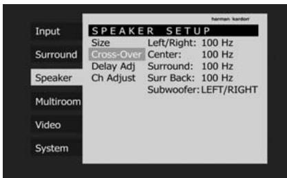
Figure 27
To change the setting for any of the four speaker groups Left/Right, Center, Surround or Surround Back, press the / Buttons 14 until the line where you wish to make a change is highlighted in blue, press the Set Button 16 followed by the Buttons 15-7 until the desired setting appears. The available choices at which point low-frequency information will be sent to the subwoofer (or to the Front Left/Right speakers in case subwoofer is set to OFF), rather than to the speaker channel, are 40Hz , 60Hz , 80Hz , 100Hz , 120Hz , 150Hz and 200Hz . Pick the choice that is identical to the information for the speakers, or if an exact match is not possible, pick the closest choice that is ABOVE the speaker's low-frequency limit to avoid the creation of a low-frequency "hole" where your system will have no bass information and press the Set Button 16 to confirm your choice.
In cases where LARGE has been selected as the front channel speaker option and SUB L/R+LFE has been selected as the subwoofer option, the front channel sound information below the crossover point selected for the L/R front speakers (when fronts are set to "Small") will be sent to BOTH the front channel speakers and the subwoofer.
The crossover settings for the Left/Right, Center, Surround and Surround Back speakers are used to determine where bass information is sent when it is derived from the main channels of a source. The setting for the menu line shown as Subwoofer is used to impose a low-pass filter point for the information in the Low Frequency Effects (LFE) channel that is a part of Dolby Digital- and DTS-encoded source material. While the LFE channel, which is the ".1" you see in surround sound designations, is restricted to low frequency sounds, some mixes may include information that is higher in frequency than your subwoofer is capable of reproducing. To prevent unwanted sounds from being sent to subwoofer that cannot handle them and which do not have a built-in low-pass filter, the Subwoofer option line enables you to select a setting for the low-pass filter that is part of the subwoofer feed from the LFE channel. The settings available are the same as those tied to any one of the four available speaker positions on this submenu. We recommend that you use the frequency that is just slightly higher than the
upper capability limit of your subwoofer, as shown in the sub's Owner's Manual. When the cursor is on the Subwoofer line, press the Navigation Buttons to choose the appropriate setting.
-
When all speaker selections have been made, press the Button until the Speaker -tab on the left is highlighted in white.
-
The Speaker Configuration may also be changed at any time without using the full-OSD on-screen menu system by pressing the Speaker Selector 6 on the front panel or 38 on the remote control. Once the button is pressed, FRONT SPEAKER will appear in both the lower third of the video display and the Main Information Display 23.
Within five seconds, either press the buttons 7 on the front panel or the buttons 14 on the remote to select a different speaker position, or press the Set Button 12 to begin the adjustment process for the front left and right speakers.
When the Set button 12 16 has been pressed and the system is ready for a change to the front speaker setting, the on-screen display and Main Information Display 23 will read FRONT LARGE or FRONT SMALL depending on the current setting. Press the buttons 7 on the front panel or the buttons 14 on the remote until the desired setting is shown, using the instructions for "large" or "small" shown earlier, then press the Set button 12 16.
If another speaker position needs to be changed, press the buttons 7 on the front panel or the buttons 14 on the remote to select a different speaker position, press the Set button 12 and then the buttons 7 on the front panel or the buttons 14 on the remote until the correct speaker setting is shown and press the Set button 12 again to confirm the selection.
To assist in making these settings, the icons in the Speaker/Channel Input Indicators 14 will change as the speaker type is selected at each position. When only the inner icon box is lit, the speaker is set for "small." When the inner box and the two outer boxes with circles inside them are lit, the speaker is set for "large." When no indicator appears at a speaker location, that position is set for "none" or "no" speaker.
Note: These icons are available only when making setup changes without the use of the full OSD mode.
As an example, in the Figure below, all speakers are set for "large," and a subwoofer is set.


Delay Settings
Due the different distances between the listening position for the front channel speakers and the surround speakers, the amount of time it takes for sound to reach your ears from the front or surround speakers is different. You may compensate for this difference through the use of the delay settings to adjust the timing for the specific speaker placement and acoustic conditions in your listening room or home theater.
If you have already calibrated your system using EzSet/EQ the delay settings shown will reflect the results of the measurements made by EzSet/EQ. No further changes are needed unless you wish to change an item to reflect your taste or a nonstandard system configuration. To change the settings, follow the instructions below to enter the distance between the speaker's location and your main listening position. The measurements need not be accurate to the centimeter, as the system is designed to accommodate typical listening rather than a specific "sweet spot" position.
In addition to adjusting the delay time for each individual speaker position, the AVR is among the few A/V receivers that allows you to adjust the delay for the combined output of all speakers as a group. This feature is called A/V Sync Delay; it allows you to compensate for delays to the video image that may be caused by the processing in products such as digital video displays, video scalers, digital cable or satellite systems, or personal video recorders. With proper adjustment of the setting for A/V Sync Delay, you can eliminate the loss of lip sync that may be caused by digital video applications.
Although EzSet/EQ calculates the delay settings for the individual speaker positions with very accurate results, the setting for A/V Sync Delay may only be done manually, since it requires that you observe the program material on your video display while adjusting the delay, if any, required for the specific source. Thus, even though you may have used EzSet/EQ for other delay settings, the A/V Sync Delay should still be configured as outlined below.
To re-synchronize the front, center and surround channels at first measure and note the distance from the listening/viewing position to the front, center, surround and surround back (if any) speakers in meters.
Due to the differences in the way each surround mode operates, the delay settings must be established individually for each surround mode. However, once the delay settings are configured for the version of the surround mode with the most channels, they need not be entered again for a version of that mode with fewer channels. For example, once the delay settings are established for Dolby Pro Logic IIx – Movie, they will be carried over to Dolby Pro Logic II – Movie mode. However, you will need to enter the delay settings separately for each variant mode, such as Dolby Pro Logic IIx – Music, Dolby Pro Logic IIx – Game, Dolby Pro Logic, Dolby 3 Stereo and Dolby Digital EX.
Delay times are adjustable for all surround modes. Although all channels will appear on screen with the default or previously entered distances, the menu system will only allow you to adjust the settings for those channels which are actually used by the current surround mode. For example, when you are listening to music CDs using the CD input in DSP Surround Off mode, you may adjust the delay settings for the front left, front right and subwoofer channels only. The cursor will simply skip the other channels as you navigate through the menu. Therefore, the first time you adjust the delay settings, it is recommended that you select a 5.1-, 6.1- or 7.1-channel surround mode, depending on the number of speakers in your system. For the purposes of setting the delay distances, the Logic 7 modes allow access to the settings for all channels without requiring that you play a source.
To start with the delay settings at first select the SPEAKER SETUP - Delay (Figure 28). If the system is not already at that point, press the OSD button 22 to bring up the main menu. Press the Button 14 twice or until the Speaker -tab is highlighted in white. Press the Set Button 16 twice, followed by the Button 14 until the Delay Adj line is highlighted in blue. Press Set 16 to access the menu.
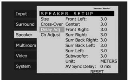
Figure 28
Next move the blue bar down to the Unit line, press Set 16 and select the unit for distances you prefer to enter, feet or meter with the use of the Buttons 1537. Then move the blue bar to the Front Left line where the first adjustment is made, and press the Set Button 16. Now press the Buttons 1537 until the distance from the front left speaker to the preferred listening position is entered followed by the Set Button 16 to confirm your choice. Next press the Button 14 once to move to the next line.
Now the blue bar will highlight the Center-line so that the delay for the center speaker may be set. Press Set 16 followed by the Buttons 1537 until the distance from the main listening position to the center speaker is entered. Repeat the procedure for all active speaker positions by pressing the Button 14 again and use the Buttons 1537 to change the setting. Remember that this last adjustment will only be needed when you have surround back speakers installed and Dolby Digital chosen as the surround mode.
When the delay time for all speaker positions has been set you may return to the main menu by pressing the Navigation Button 15 several times.
However, if you have a digital video source or a digital video display that causes lack of lip sync you may use the A/V Sync adjust feature to delay the audio signal as it is sent to all channels (as opposed to the individual settings) so that the picture and sound are brought back together. We recommend that this adjustment be made using the direct access controls on the remote, as shown below. That enables you to see the image while making the adjustment; however, you may also adjust it here using the menu system.
To adjust the A/V Sync delay, press the / Navigation Button 14 so that the blue bar is highlighting the AV Sync Delay -line on the menu, followed by the Set Button 16, and then press the / Navigation Button 1537 to delay the sound sufficiently so that it matches the on-screen video.
The delay settings may be adjusted at any time using the remote control and while viewing an on-screen image by pressing the Delay Select Button 36. The A/V Sync Delay setting is first, and it may be adjusted by pressing the Set Button 16 within five seconds of when the A/V SYNC DELAY message appears in the on-screen display and the Lower Display Line 23. Then, press the / Navigation Button 14 to enter the desired delay setting that brings the video and sound back in sync. Press the Set Button 16 again to enter the setting.
Note that the A/V Sync delay setting is unique to each video input source, so you may enter a different setting to compensate for the differences between any product attached to the Video 1, 2, 3 or 4 inputs.
To change one of the individual speaker positions directly, press the Delay Select Button 36, followed by the / Navigation Button 14 to select the desired position as that name appears in the on-screen display and the Lower Display Line 28. When the name of the speaker position to be adjusted appears press the Set Button 16 within five seconds. Press the / Navigation Button 14 to enter the desired delay setting for that speaker and then press the Set Button 16 to enter the setting. The / Navigation Button 14 may be used to select another position, or you may simply wait five seconds for the system to time out and return to normal operation.
The delay settings may be adjusted at any time using the remote control and while viewing an on-screen image by pressing the Delay Select Button 35.
Output Level Adjustment
Output level adjustment is a key part of the configuration of any surround-sound product. It is particularly important for a digital receiver such as the AVR, as correct outputs ensure that you hear sound tracks with the proper directionality and intensity.
NOTE: Listeners are often confused about the operation of the surround channels. While some assume that sound should always be coming from each speaker, most of the time there will be little or no sound in the surround channels. This is because they are only used when a movie director or sound mixer specifically places sound there to create ambience, a special effect or to continue action from the front of the room to the rear. When the output levels are properly set, it is normal for surround speakers to operate only occasionally. Artificially increasing the volume to the rear speakers may destroy the illusion of an enveloping sound field that duplicates the way you hear sound in a movie theater or concert hall.
If you have already calibrated your system using EzSet/EQ the output level adjustments shown will reflect the results of the measurements made by EzSet/EQ. No further changes are needed unless you wish to change a specific item to reflect your personal taste or a non-standard system configuration.
When the AVR is configured for 6.1-channel operation using a single surround back speaker, the output level adjustments will still provide an adjustment for separate surround back left and surround back right positions even though your system has only one surround back speaker. This
means that the Surround Back channel will seem to appear twice, and in 6.1 operation this is normal. The separate SBL/SBR adjustments for 6.1 operation are needed to optimize the balance between the two discrete channels within the AVR as they are mixed for output to a single speaker.
IMPORTANT NOTE: The output level can be adjusted for each digital and analog surround mode individually. This allows you to compensate for level differences between speakers, that may also vary with the surround mode selected, or to increase or decrease the level of certain speakers intentionally, depending on the surround mode selected. Note that adjustments made for any surround mode are effective with all inputs associated with the same surround mode.
Before beginning the output level adjustment process, make certain that all speaker connections have been properly made. The system volume should be turned down at first.
For the easiest set-up, follow these steps while seated in the listening position that will be used most often:
- Make certain that all speaker positions have been properly configured for their "large" or "small" settings (as outlined above) and turn off the OSD system if it is in use.
- Adjust the volume so that it is at -1, 5, as shown in the on-screen display or Main Information Display 28.
- Select any input associated with the surround mode for which you want to adjust the output levels. Remember that the same adjustments must be made with all other surround modes you've in use.
- Manual output level adjustment is most easily done through the Ch Adjust menu (Figure 29). If you are already at the main menu, press the Button 14 until the Speaker -tab is highlighted in white. If you are not at the main menu, press the OSD Button 22 to bring up the main menu (Figure 1), and then press the Button 14 two times so that the Speaker -tab is highlighted in white. Press the Set Button 16 to highlight the Manual
Configuration-line,and press Set 16.Now scroll down until the Ch Adjust-line is highlighted in blue and press the Set Button 16.
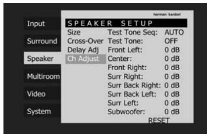
Figure 29
When the SPEAKER SETUP - Ch Adjust menu first appears, the test tone is off. Use the / Navigation Button 14 and the Set Button 16 to select any channel for adjustment using an external source, such as a test disc, from which to judge the output levels. When the channel to be adjusted, is highlighted in blue, press the Set Button 16 followed by the Navigation Button 15 to raise or lower the output level. However, before proceeding with any manual adjustment we recommend that you first use the AVR's internal test tone generator and automatic sequencer to send a tone to each channel so that you may verify that all speaker connections have been properly made.
- To turn the test tone on and have it automatically circulate among the channels where a speaker has previously been configured (see page 31), press the / Navigation Button until the Test Tone Seq-line is highlighted in blue. Next, press the Set Button, followed by the Navigation Button until AUTO is shown. At this time the test tone will immediately begin to circulate clockwise around the room, playing for two seconds in each speaker before switching to the next speaker position. The text presenting the active speaker will highlight in blue to indicate which speaker the sound should be coming from.
IMPORTANT NOTE: Because this test noise will have a much lower level than normal music, the volume must be lowered after the adjustment for all channels is made, but BEFORE you return to the main menu and the test tone turns off.
NOTE: Remember to verify that the speakers have been properly connected. As the test noise circulates, listen to make certain that the sound comes from the speaker position shown in the Main Information Display 23. If the sound comes from a speaker location that does NOT match the position indicated in the display, turn the AVR off using the Main Power Switch 1 and check the speaker wiring or connections to external power amplifiers to make certain that each speaker is connected to the correct output terminal.
NOTE: Remember that when your system has only a single Surround Back speaker and is thus configured for 6.1-channel operation, you will
hear the test tone twice from the back speaker, once with the SBL indication and once with the SBR indication. This is normal, and it allows you to adjust the output balance for the mixing circuit that creates a 6.1 output when
7.1 modes such as Logic 7/7.1 are used.
- After checking for speaker placement, let the test noise circulate again, and listen to see which channels sound louder than the others. Using the front left speaker as a reference, press the Buttons 1537 on the remote when the text of the loudspeaker to be adjusted is lit in blue, to bring all speakers to the same volume level. When one of the buttons is pushed, the test noise circulation will pause on the channel being adjusted to give you time to make the adjustment. When you release the button, the circulation will resume after five seconds. The on-screen cursor-bar and the test noise can also be moved directly to the speaker to be adjusted by pressing the
/ buttons 14 on the remote.
- Continue to adjust the individual channels until the volume level sounds the same from each speaker. Note that adjustments should be made with the Buttons 1537 on the remote only, NOT the main volume controls.
If you are using a sound-pressure level (SPL) meter for precise level adjustment with the test tone, open the main Volume Control 40 to -15dB and set the individual output level for each channel so that the meter reads 75dB, C-Weighted Slow. After all settings are made turn the main volume down.
You may also make these same adjustments with complete manual control over the channel being adjusted by pressing the
/ Navigation Button 14 until the blue cursor-bar is highlighting the Test Tone Seq-line on the menu, pressing the Set Button 16 and then using the
Navigation Button 15 to select MANUAL. In the MANUAL mode, the test tone will also start immediately, but the tone will only be moved to another channel by pressing the / Navigation Button 14. When the manual sequencing mode is active, the tone is turned off by pressing the / Navigation Button 14 until the blue cursor-bar is highlighting the Test Tone-line, followed by pressing the Set Button 16 and the Navigation Button 15 is then pressed to select F F in the highlighted video.
If you find that the output levels are either uncomfortably low or high, you may repeat the procedure. Return to Step 2 and adjust the master volume either slightly higher or lower to accommodate your particular room layout and your tastes. You may repeat this procedure as many times as necessary to achieve a desired
result. In order to prevent possible damage to your hearing or your equipment, we emphasize that you should avoid setting the master volume above 0dB.
When all channels have an equal volume level, the adjustment is complete. Use the / Buttons 14 to highlight the Test Tone -line in blue, pressing Set 16 followed by the / Buttons 1537 until the word OFF appears to stop the test tone.
Note that any time a given surround mode is selected, even for a different source input, these output level settings will be used. However, the output levels must be set independently for each surround mode, including variations such as Dolby Pro Logic II-Movie versus Dolby Pro Logic II-Music. Although this may seem to be tedious, it is necessary in order to optimize the AVR's performance when differing methods are employed to steer the audio materials to the various channels. However, the AVR will carry over the settings for one mode to the same mode in a different channel configuration, such as Dolby Pro Logic IIx-Movie and Dolby Pro Logic II-Movie. If you wish, as a shortcut to get started quickly, you may set the levels for Dolby Pro Logic IIx-Movie and copy down those settings, reentering them for each of the Dolby modes and entering the settings only for those speakers which are available for each mode. Later, it is recommended that you adjust the output levels while listening to various sources, as opposed to the test tone. See page 46 for more information on trimming the output levels to external source material.
NOTE: The subwoofer output level is not adjustable using the test tone. To change the subwoofer level, follow the steps for Output Level Trim Adjustment on page 46.
When all channels have an equal volume level, the adjustment is complete. Now turn the Volume 40 down to about -40dB, otherwise the listening level may be too high as soon as the source's music starts to play. To exit this menu, press the
The output levels may also be adjusted at any time using the remote control and semi-OSD system. To adjust the output levels in this fashion, press the Test Button 9. As soon as the button is pressed, the test tone will begin to circulate as indicated earlier. The correct channel from which the test noise should be heard will be shown in the lower third of the video screen and in the Main Information Display 23. While the test noise is circulating, the proper channel position will also be indicated in the Speaker/Channel Input Indicators 14 by a blinking letter within the correct channel. Turn up the Volume 40 until you can hear the test noise clearly.
To adjust the output level, press the
/ buttons 14 until the desired level is shown in the display or on screen. Once the buttons are released, the test noise will begin to circulate again in five seconds.
When all channels have the same output level, turn the Volume 40 down to about -40dB otherwise the listening level may be too high as soon as the source's music starts to play. Afterwards press the Test Tone Selector 9 button again to turn the test tone off and complete the process.
IMPORTANT NOTE: The Output level adjustment made will be effective for all inputs, but only for the actual surround mode selected. To be effective for any other mode select that mode (with any input) and repeat the level adjustment described above. This will also allow you to compensate level differences between speakers, that may be different with each surround mode, or to increase or decrease the level of certain speakers intentionally, depending on the surround mode selected.
Note: Output level adjustment is not available for the Surround Off mode, as no surround speakers are used (so level differences between the speakers in the room cannot occur). But to compensate level differences between stereo and other surround modes (independently from the input selected) the outputs can be adjusted with the Level Trim Adjustment procedure, see page 46 also for the Surround Off (Stereo) modes.
After one input has been adjusted for analog or digital input, speaker type and surround mode, return to the Input -tab on the left of the menu and press the Set Button 16 to enter the settings for each input that you will use.
Once the settings outlined on the previous pages have been made, the AVR is ready for operation. While there are some additional settings to be made, these are best done after you have had an opportunity to listen to a variety of sources and different kinds of program material. These advanced settings are described on pages 49-51 of this manual. In addition, any of the settings made in the initial configuration of the unit may be changed at any time. As you add new or different sources or speakers, or if you wish to change a setting to better reflect your listening taste, simply follow the instructions for changing the settings for that parameter as shown in this section.
Note that any settings changed at any time, also when the discrete buttons are used only, will be stored in memory in the AVR, also if it's turned off completely, unless it will be reset (see page 60).
Having completed the setup and configuration process for your AVR, you are about to experience the finest in music and home theater listening. Enjoy!
Surround Mode Chart
| MODE | FEATURES |
| DOLBY DIGITAL | Available only with digital input sources encoded with Dolby Digital data. It provides up to five separate main audio channels and a special dedicated Low Frequency Effects channel. |
| DOLBY DIGITAL EX | Available when the receiver is configured for 6.1/7.1 channel operation, Dolby Digital EX is the latest version of Dolby Digital. When used with movies or other programs that have special encoding, Dolby Digital EX reproduces specially encoded soundtracks so that a full 6.1/7.1 soundfield is available. When the receiver is set for 6.1/7.1 operation and a Dolby Digital signal is present, the EX mode is automatically selected. Even if specific EX encoding is not available to provide the additional channel, the special algorithms will derive a 6.1/7.1 output. |
| DTS 5.1 | When the speaker configuration is set for 5.1-channel operation, the DTS 5.1 mode is available when DVD, audio-only music or laserdiscs encoded with DTS data are played. DTS 5.1 provides up to five separate main audio channels and a special dedicated low-frequency channel. |
| DTS-ES 6.1 Matrix DTS-ES 6.1 Discrete | When the speaker configuration is set for 6.1/7.1 operation, playback of a DTS-encoded program source will automatically trigger the selection of one of the two DTS-ES modes. Newer discs with special DTS-ES discrete encoding will be decoded to provide six discrete, full-bandwidth channels plus a separate low-frequency channel. All other DTS discs will be decoded using the DTS-ES Matrix mode, which creates a 6.1-channel sound field from the original 5.1-channel soundtrack. |
| DOLBY PRO LOGIC II MOVEMUSICDOLBY PRO LOGICGAME | Dolby Pro Logic II is the latest version of Dolby Laboratory's benchmark surround technology that decodes full-range, discrete left, center right, right surround and left surround channels from matrix surround encoded programs and conventional stereo sources when an analog input or a digital input with PCM or Dolby Digital 2.0 recordings is in use. The Dolby Pro Logic II Movie mode is optimized for movie soundtracks that are recorded with matrix surround, by creating separate center, rear left and rear right signals. while the Pro Logic II Music mode should be used with musical selections that are recorded with matrix surround or even with normal stereo mode, creating separate rear left and rear right signals in any case. The Pro Logic II mode creates compelling five-channel surround sound from conventional stereo recordings. Game mode ensures that special effects are routed to the surround channels, while delivering their full impact using the subwoofer, thus fully immersing the game player in the universe of the video game. |
| DOLBY PRO LOGIC Ilx MUSICMOVIGAME | Dolby Pro Logic Ilx is the latest extension of Dolby Pro Logic II technology that creates a discrete 6.1 and 7.1 sound field from matrix surround or two-channel stereo sources in systems configured for surround back speakers. Movie, Music and Game versions of Pro Logic Ilx are available. Game mode ensures that special effects are routed to the surround channels, while delivering their full impact using the subwoofer, thus fully immersing the game player in the universe of the video game. |
| Logic 7 Cinema Logic 7 Music Logic 7 Enhance | Exclusive to Harman Kardon for AV receivers, Logic 7 is an advanced mode that extracts the maximum surround information from either surround-encoded programs or conventional stereo material. Depending on the number of speakers in use and the selection made in the SURROUND SELECT menu, the "5.1" versions of Logic 7 modes are available when the 5.1 option is chosen, while the "7.1" versions of Logic 7 produce a full sound field presentation, including back surround speakers when the "6.1/7.1" option is chosen. The Logic 7 C (or Cinema) mode should be used with any source that contains Dolby Surround or similar matrix encoding. Logic 7 C delivers increased center-channel intelligibility, and more accurate placement of sounds with fades and pans that are much smoother and more realistic than with former decoding techniques. The Logic 7 M or Music mode should be used with analog or PCM stereo sources. Logic 7 M enhances the listening experience by presenting a wider front soundstage and greater rear ambience. Both Logic 7 modes also direct low-frequency information to the subwoofer (if installed and configured) to deliver maximum bass impact. The Logic 7 E (or Enhance) mode is an extension of the Logic 7 modes that is primarily used with musical programs and is available with the 5.1 surround mode option selected only. Logic 7 E adds additional bass enhancement that circulates low frequencies in the 40Hz to 120Hz range to the front and surround speakers to deliver a less localized soundstage that appears broader and wider than when the subwoofer is the sole source of bass energy. |
Surround Mode Chart
| MODE | FEATURES |
| DTS Neo:6 Cinema | These two modes are available when any analog source is playing to create a six-channel surround presentation from conventional Matrix-encoded and traditional Stereo sources. Select the Cinema version of Neo:6 when a program with any type of analog Matrix surround encoding is present. Select the Music version of Neo:6 for optimal processing when a nonencoded, two-channel stereo program is being played. When selecting a DTS Neo:6 Cinema mode, a 3-, 5- or 6-channel configuration may be available, depending on the number of speakers in your system. Use 3-channel mode when only a front left and right and a center speaker are present; surround-channel information will be mixed into these speakers. The 6-channel mode will only be available if you have configured your surround back speakers as active. |
| DTS Neo:6 Music | |
| DTS 96/24 | DTS 96/24 is a high-resolution format that uses a 96kHz sampling rate with 24 bits to produce extended information that improves the harmonics of the source material. The AVR is capable of automatically detecting and decoding DTS 96/24 materials and delivering them as the artist intended. |
| Dolby 3 Stereo | Uses the information contained in a surround-encoded or two-channel stereo program to create center-channel information. In addition, the information that is normally sent to the rear-channel surround speakers is carefully mixed in with the front-left and front-right channels for increased realism. Use this mode when you have a center channel speaker but no surround speakers. |
| Dolby Virtual Speaker Reference Wide | Dolby Virtual Speaker technology uses a next-generation advanced algorithm to reproduce the dynamics and surround sound effects of a precisely placed 5.1-channel speaker system using only front left and right speakers. In the Reference Mode, the apparent width of the sound across the front image is defined by the distance between the two speakers. The Wide Mode provides a wider, more spacious front image when the two speakers areclose together. |
| THEATER | The THEATER mode creates a 5.1 or 6.1 sound field that resembles the acoustic feeling of a standard live performance theater, with stereo and even pure mono sources. |
| HALL 1 | The two Hall modes create 5.1 or 6.1 sound fields that resemble a small (HALL1) or medium sized (HALL 2) concert hall, with stereo and even pure mono sources. |
| HALL 2 | |
| 5-Channel Stereo 7-Channel Stereo | This mode takes advantage of multiple speakers to place a stereo signal at both the front and back of a room. Depending on whether the AVR has been configured for either 5.1 or 6.1/7.1 operation, one of these modes, but not both, is available at any time. Ideal for playing music in situations such as a party, this mode places the same signal at the front-left and surround-left, and at the front-right and surround-right speakers. The center channel is fed a summed mono mix of the in-phase material of the left and right channels. |
| Surround Off (Stereo) | These modes turn off all surround processing and present the pure left- and right-channel presentation of two-channel stereo programs. The Surround Off (Bypass) mode may only be used with analog source inputs, as it preserves the analog format of the audio signal for its entire path of travel through the receiver to the speaker and subwoofer outputs, bypassing all digital processing. Digital bass management is not available in Surround Off mode. The DSP Surround Off mode can be used with either an analog or digital input, as the signal undergoes digital bass management to optimize the distribution of the low frequencies between the main speakers and a subwoofer. |
| Surround Off (Bypass) | |
| DSP Surround Off | |
| Doply Headphone DH | Dolby Headphone enables ordinary stereo headphones to portray the sound of a five-speaker surround-playback system. |
Basic Operation
Once you have completed the setup and configuration of the AVR, it is simple to operate and enjoy. The following instructions should be followed for you to maximize your enjoyment of your new receiver:
Turning the AVR On or Off
- When using the AVR for the first time, you must press the Main Power Switch 1 on the front panel to turn the unit on. This places the unit in a Standby mode, as indicated by the amber color of the Power Indicator 3. Once the unit is in Standby, you may begin a listening session by pressing the System Power Control 2 or the Source button 15 on the front panel or the AVR Selector 6. Note that the Power Indicator 3 will turn white. This will turn the unit on and return it to the input source that was last used. The unit may also be turned on from Standby by pressing any of the Source Selector buttons on the remote 5 6 7 8 C D or the Source button 15 on the front panel.
NOTE: After pressing one of the Input Selector buttons (except VID3) to turn the unit on, press the AVR Selector to have the remote control the AVR functions.
To turn the unit off at the end of a listening session, simply press the System Power Control 2 on the front panel or the Power Off Button 4 A on the remote. Power will be shut off to any equipment plugged into the rear panel Switched AC Outlets 7 and the Power Indicator 3 will turn orange.
When the remote is used to turn the unit "off" it is actually placing the system in a Standby mode, as indicated by the orange color of the Power Indicator 3.
When you will be away from home for an extended period of time it is always a good idea to completely turn the unit off with the front panel Main Power Switch 1.
NOTE: All preset memories may be lost if the unit is left turned off with the Main Power Switch 1 for more than two weeks.
Using the Sleep Timer
- To program the AVR for automatic turn-off, press the Sleep Button 10 on the remote. Each press of the button will increase the time before shut down in the following sequence:
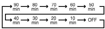
The sleep time will be displayed in the Main Information Display 23 and it will count down until the time has elapsed.
When the programmed sleep time has elapsed, the unit will automatically turn off (to Standby mode). Note that the front panel display will dim to one half brightness when the Sleep function is programmed. To cancel the Sleep function, press and hold the Sleep Button 10 until the information display returns to normal brightness and the Sleep indicator numbers disappear and the words SLEEP OFF appear in the Main Information Display 28.
Source Selection
For direct access to any source, press its Input Selector 57841CD on the remote. Since the AVR 350 allows for more source input devices than the remote has buttons for, some sources are required to share buttons. These are the DVD and CD sources, the Tape and The Bridge sources, and the HDMI 1 and HDMI 2 sources. The first press of any of these three Input Selectors will select the source whose name appears on the button, i.e., DVD, Tape or HDMI 1. Press that Input Selector again to select the source whose name appears above the button (i.e., CD, The Bridge or HDMI 2), and the LED on the remote will light in green to indicate that you have selected the source whose name is printed in green above the button. Each additional press toggles between the two sources.
NOTE: After pressing one of the Input Selector buttons 5 to turn the unit on, press the AVR Selector 6 to have the remote control the AVR functions.
- The input source may also be changed by pressing the front-panel Input Source Selector button 15. Each press of the button will move the input selection through the list of available inputs.
- The front-panel Video 4 Inputs 21, Optical Digital 4 Input 18 or the Coaxial Digital 4 Input 20 may be used to connect a device such as a video game or camcorder to your home entertainment system on a temporary basis.
-
As the input source is changed, the new input name will appear momentarily as an on-screen display in the lower third of the video display. The input name will also appear in the Main Information Display 23 and a blue LED will light next to the selected input's name in the front-panel Input Indicators 22.
-
When ^The Bridge Digital Media Player (DMP) source is selected, if a compatible Apple iPod device is inserted in an optional Harman Kardon ^The Bridge that is connected to ^The Bridge DMP
Connector 9 on the rear panel, function messages will appear on any video display connected to the AVR's Video Monitor
Outputs 12, and the remote control may be used to navigate the iPod and access many of its functions. The function messages will also appear in the front-panel display, and the iPod's battery may be charged. See the owner's guides for ^TM Bridge and your iPod for more information.
Video Input Selection
When a source is selected, the AVR switches to a video input as follows:
The Video In line of the Input Setup menu indicates which of the component video inputs on the AVR is assigned to each source. By default the Component Video 1 input is assigned to the DVD source, the Component Video 2 input is assigned to the Video 1 source, and the Component Video 3 input is assigned to the Video 2 source.
The two HDMI inputs obtain the video signal from their own inputs, and may not be reassigned to another video input.
If your iPod is capable of playing still-images and videos, it may be used as a video source. However, you may reassign the video input for The Bridge to another device for viewing while listening to audio files stored on the iPod.
All other sources default to the Composite setting, meaning that they may only be used with their composite or S-video inputs. The AVR will transcode the incoming composite or S-video signal and make it available using the HDMI or component video monitor outputs, enabling a single-cable connection to your television.
The component video inputs may be reassigned to other source inputs as needed, depending on the physical connections you made during the Installation procedure.
If a signal is present at the component video input assigned to that source, it will be selected.
If no signal is present at the component video input, then the S-video or composite video input for the source will be selected. It is not possible to reassign the S-video or composite video inputs to other sources.
For audio-only sources, such as the tuner or CD inputs, when no component video signal is present, the last-used video source will be selected.
6-Channel/8-Channel Direct Input
- There are two input choices available for use with sources such as a DVD-Audio or SACD player that are connected to the 8-Channel Direct Inputs 10 . Select the appropriate input according to the way your system and source equipment is configured:
- The CH DIRECT INPUT should be used when the Surround Back Left and Right inputs are NOT in use and the input source device has its own internal bass management system. This input passes the input from the source directly through to the volume control without any analog to digital conversion and it mutes the unused input jacks to prevent unwanted noise from interfering with system performance.
- The &CH DIRECT INPUT should be used when an input is connected to all eight 8-Channel Direct Inputs 10 and when the input source device has its own internal bass management system. This input passes the input from the source directly through to the volume control without any analog to digital conversion and it mutes the unused input jacks to prevent unwanted noise from interfering with system performance.
Note that when the 6-Channel or 8-Channel Direct Input is in use, you may not select a surround mode, as the external decoder determines the processing in use. In addition, there is no signal at the record outputs or bass management when the 6-Channel or 8-Channel Direct Input is in use and the tone or balance controls will not function.
Controls and Use of Headphones
- Adjust the volume to a comfortable level using the front panel Volume Control 27 or remote Volume Up/Down 40 F buttons.
-
To temporarily silence all speaker outputs press the Mute button 39. This will interrupt the output to all speakers and the headphone jack, but it will not affect any recording or dubbing that may be in progress. When the system is muted, the word MUTE will blink in the Main Information Display 28. Press the Mute button 39 again to return to normal operation.
-
To set the output of the AVR so that the output is "flat," with the tone and balance controls de-activated, press the Tone Mode button 3 once or twice so that the words Tone 0 f f appear momentarily in the Main Information Display 28. To return the tone controls to an active condition, press the Tone Mode 8 button once or twice so that the words Tone I n momentarily appear in the Main Information Display 28.
- For private listening, plug the 6.3 mm stereo phone plug from a pair of stereo headphones into the front panel Headphone Jack 4. Note that when the headphone's plug is connected, the word DOLBYH:BP will scroll once across the Main Information Display 28 and all speakers will be silenced. When the headphone plug is removed, the audio feed to the speakers will be restored.
- When the headphones are in use, you may take advantage of the Dolby Headphone modes to bring added spaciousness to headphone listening. Press the Dolby Mode Select Button 23 or the Surround Mode Group Selector 5 to cycle through the three Dolby Headphone modes to select the one that you prefer.
Surround Mode Selection
One of the most important features of the AVR 350 is its ability to reproduce a full multi-channel surround sound field from digital sources, analog matrix surround encoded programs and standard stereo or even mono programs.
Selection of a surround mode is based on personal taste, as well as the type of program source material being used. For example, CDs, motion pictures or TV programs bearing the logo of one of the major surround-encoding processes, such as Dolby Surround should be played in either the Dolby Pro Logic II or Ilx Movie (with movies) or Music (with music) surround mode, with any DTS NEO:6 mode or with Harman Kardon's exclusive Logic 7 Movie Mode, to create a full range 5.1 channel or (with Logic 7 and DTS NEO:6) even 7.1 channel surround signal from surround encoded programs, with a stereophonic left and right rear signal, just as it was recorded (e.g. sound being recorded from left rear side will be heard from that side only, for more details see chart on page 37-38).
Note that when Dolby Digital 2.0 signals (e.g. "D.D. 2.0" tracks from DVD), that are encoded with Dolby Pro Logic information, are received via any digital input, the Dolby Pro Logic II Movie mode will be selected automatically (in addition to the Dolby Digital mode) and will decode a full range 5.1 channel surround sound even from those recordings (see also "Dolby Digital" on page 41).
To create wide, enveloping sound field environments and defined pans and flyovers with all analog stereo recordings select the Dolby Pro Logic II Music or Emulation mode or Harman Kardon's exclusive Logic 7 Music mode for a dramatic improvement in comparison to the Dolby Pro Logic (I) mode of former times.
NOTE: Once a program has been encoded with matrix surround information, it retains the surround information as long as the program is broadcast in stereo. Thus, movies with surround sound may be decoded via any of the analog surround modes such as Pro Logic II or Ilx Cinema, Logic 7 Cinema or DTS Neo:6 Cinema, when they are broadcast via conventional TV stations, cable, pay-TV and satellite transmission. In addition, a growing number of made-for-television programs, sports broadcasts, radio dramas and music CDs are also recorded in surround sound. You may view a list of these programs at the Dolby Laboratories Web site at www.dolby.com
Even when a program is not listed as carrying intentional surround information, you may find that the Dolby Pro Logic II or Ilx Music, DTS NEO:6 Music or Logic 7 Music or Enhanced modes often deliver enveloping surround presentations through the use of the natural surround information present in all stereo recordings.
However, for stereo programs without any surround information the Theater, Hall and 5/7CH Stereo modes should be tried (effective particularly with old "extreme" stereo recordings) and for mono programs, we suggest that you try the Theater or Hall modes. And when you use only two front channel speakers you should select any of the Dolby Virtual Speaker surround modes, delivering a virtually three dimensional sound space with two speakers only.
Surround modes are selected using either the front panel controls or the remote. To select a new surround mode from the front panel, first press the Surround Mode Group Selector Button 5 until the desired major surround mode group such as Dolby, DTS or Logic 7 is selected. Next, press the Surround Mode Selector Button 9 to choose the specific individual surround mode.
To select a surround mode using the remote control, press the button for the major surround mode group that includes the mode you wish to choose from: Dolby 23, DTS Surround 24, DTS Neo:6 30, Logic 7 25, Stereo 29 or DSP Surround 11. The first press of the button will show the current mode from that group if it is already in use, or the first available mode if you are currently using another mode. To cycle through the available modes in that group press the button again until the desired mode appears in the Main Information Display 23 and the on-screen display.
To select from the DSP modes (Hall 1, Hall 2, Theater) press the Surround Mode Selector repeatedly to scroll through the list of available modes.
As the surround modes change, a blue LED will light next to the current mode in the Surround Mode Indicators 19 list on the front panel.
Note that the Dolby Digital or DTS modes may only be selected when a digital input is in use. In addition, when a digital source is present, the AVR will automatically select and switch to the correct mode (Dolby Digital or DTS), regardless of the mode that has been previously selected. For more information on selecting digital sources, see the following section of this manual.
When the 6-Channel/8-Channel direct inputs are in use there is no surround processing, as these inputs take the analog output signals from an optional, external DVD-Audio or SACD player, or another source device and carry them straight through to the volume control.
To listen to a program in traditional two-channel stereo, using the front left and front right speakers only (plus the subwoofer, if installed and configured), press the Stereo Button
529 until SURR OF F appears in the Main Information Display 28.
Digital AudioPlayback
Digital audio is a major advancement over older analog surround processing systems such as Dolby Pro Logic. It delivers five, six or seven discrete channels: left front, center, right front, left surround and right surround and with DTS ES (see below) even surround back (with left and right). Each channel reproduces full frequency range (20Hz to 20kHz) and offers dramatically improved dynamic range and significant improvements to signal-to-noise ratios. In addition, digital systems have the capability to deliver an additional channel that is specifically devoted to low-frequency information. This is the ".1" channel referred to when you see these systems described as "5.1," "6.1" or "7.1". The bass channel is separate from the other channels, but since it is intentionally bandwidth-
limited, sound designers have given it that unique designation.
Dolby Digital
Dolby Digital (originally known as AC-3®) is a standard part of DVD, and is available on specially encoded LD discs and satellite broadcasts and it is a part of the new high-definition television (HDTV) system.
Note that an optional, external RF demodulator is required to use the AVR to listen to the Dolby Digital sound tracks available on laser discs. Connect the RF output of the LD player to the demodulator and then connect the digital output of the demodulator to the Optical or Coaxial inputs 23241820 of the AVR. No demodulator is required for use with DVD players or DTS-encoded laser discs.
DTS
DTS is another digital audio system that is capable of delivering 5.1, 6.1 or 7.1 audio. Although both DTS and Dolby Digital are digital, they use different methods of encoding the signals, and thus they require different decoding circuits to convert the digital signals back to analog.
DTS-encoded sound tracks are available on select DVD and LD discs, as well as on special audio-only DTS CDs. You may use any LD, DVD or CD player equipped with a digital output to play DTS-encoded special audio-only CDs with the AVR, but DTS-LDs can be played on LD players and DTS-DVDs on DVD players only. All that is required is to connect the player's digital output to either the Optical or Coaxial input on the rear panel 28 24 or front panel 18 20.
In order to listen to DVDs encoded with DTS sound tracks, the DVD player must be compatible with the DTS signal as indicated by a DTS logo on the player's front panel. Note that early DVD players may not be able to play DTS-encoded DVDs. This does not indicate a problem with the AVR, as some players cannot pass the DTS signal through to the digital outputs. If you are in doubt as to the capability of your DVD player to handle DTS DVDs, consult the player's owner's manual.
Please note that some DVD players are shipped with their output set for Dolby Digital only. To insure that DTS data is being sent to the AVR, please check the setup menu system on your DVD player to make certain that DTS data output is enabled.
PCM Audio Playback
PCM (Pulse Code Modulation) is the non- compressed digital audio system used for compact discs, Non-Dolby Digital/DTS Laserdiscs and some special PCM encoded DVDs. The digital circuits in the AVR are capable of high quality digital-to-analog decoding, and they may be connected directly to the digital audio output of your CD/DVD or LD player (LD only for PCM or DTS programs, for Dolby Digital laser discs an RF adapter is needed, see "Dolby Digital" above).
Connections may be made to either the Optical or Coaxial inputs 2624 on the rear panel or the front panel Digital Inputs 1820.
To listen to a PCM digital source, first select the input for the desired source (e.g., CD) to feed its video signal (if any) to the TV monitor and to provide its analog audio signal for recording. Next press the Digital Select button 25 17 and then use the / buttons 14 on the remote, or the Selector buttons 7 on the front panel, until the desired choice appears in the Main Information Display 28, then press the Set button 12 16 to confirm the choice.
During PCM playback the unit automatically will turn to the default surround mode or to the LOGIC7 mode but you also may select any surround mode except Dolby Digital or DTS.
Selecting a Digital Source
To utilize either digital mode you must have properly connected a digital source to the AVR. Connect the digital outputs from DVD players, HDTV receivers, satellite systems or CD players to the Optical or Coaxial inputs on the rear or front panel 28241820. In order to provide a backup signal and a source for analog stereo recording, the analog outputs provided on digital source equipment should also be connected to their appropriate inputs on the AVR rear panel (e.g., connect the analog stereo audio output from a DVD to the DVD Audio inputs 6 on the rear panel when you connect the source's digital outputs).
To select a digital source such as DVD, first select its input using the remote or front panel Input Selector 5 15 as outlined in this manual in order to feed its video signal (if any) to the TV monitor and to provide its analog audio signal for recording. When the digital input associated with the input selected (e.g. "DVD") is not selected automatically (due to the input settings made earlier during the system configuration, see page 21), select the digital source by pressing the Digital Input Selector button 17 25 and then using the / buttons 14 on the remote or the Selector buttons 7 on the front panel to choose any of the OPTICAL or COAXIAL inputs, as they appear in the Main Information Display 23 or on-screen display.
When the digital source is playing, the AVR will automatically detect whether it is a multichannel Dolby Digital or DTS source or a conventional PCM signal, which is the standard output from CD players.
Note that a digital input (e.g. coaxial) remains associated with any analog input (e.g. DVD) as soon as it is selected, thus the digital input need not be re-selected each time the appropriate input choice (e.g. DVD) is made.
Digital Bitstream Indicators
When a digital source is playing, the AVR senses the type of bitstream data that is present. Using this information, the correct surround mode will automatically be selected. For example, DTS bitstreams will cause the unit to switch to DTS decoding, and Dolby Digital bitstreams will enable Dolby Digital decoding. When the unit senses PCM data, from CDs and LDs and some music DVDs or certain tracks on normal DVDs, it will allow the appropriate surround mode to be selected manually. Since the range of available surround modes depends on the type of digital data that is present, the AVR uses a variety of indicators to let you know what type of signal is present. This will help you to understand the choice of modes and the input channels recorded on the disc.
When a digital source is playing, the AVR will display a variety of messages to indicate the type of bitstream received. These messages will appear shortly after an input or surround mode is changed, and will remain in the Main
Information Display 28 for about five seconds before the display returns to the normal surround mode indication.
Surround Mode Types
For Dolby Digital and DTS sources, a three digit indication will appear, showing the number of channels present in the data. An example of this type of display is 3/2/.1.
The first number indicates how many discrete front channel signals are present.
- A 3 tells you that separate front left, center and front right signals are available. This will be displayed for Dolby Digital 5.1 and DTS 5.1 programs.
- A 2 tells you that separate front left and right signals are available, but there is no discrete center channel signal. This will be displayed for Dolby Digital bit streams that have stereo program material.
- A 1 tells you that there is only a mono channel available in the Dolby Digital bitstream.
The middle number indicates how many discrete surround channel signals are present.
- A 2 tells you that separate surround left and right signals are available. This will be displayed for Dolby Digital 5.1 and DTS 5.1 programs.
- A 1 tells you that there is only a single, surround encoded surround channel. This will appear for Dolby Digital bit streams that have matrix encoding.
- A 0 indicates that there is no surround channel information. This will be displayed for two-channel stereo programs.
The last number indicates if there is a discrete Low Frequency Effects (LFE) channel. This is the ".1" in the common abbreviation of "5.1" sound and it is a special channel that contains only bass frequencies.
- A .1 tells you that an LFE channel is present. This will be displayed for Dolby Digital 5.1 and DTS 5.1 programs, as available.
- A 0 indicates that there is no LFE channel information available. However, even when there is no dedicated LFE channel, low frequency sound will be present at the subwoofer output when the speaker configuration is set to show the presence of subwoofer.
- The information in the right side of the display will tell you if the digital audio data contains a special flag signal that will automatically activate the appropriate 6.1 or 7.1 mode. This will be shown as EX-ON or EX-OFF for Dolby Digital bitstreams and ES-ON or ES-OFF for DTS bitstreams.
An UNL OK message may appear in the Lower Display Line 23. This is your indication that the digital audio data stream has been interrupted or is no longer present. When that occurs, the unit's digital signal processor has no signal to lock onto, and is thus "unlocked." You may see this message when a DVD is first started until the stream is playing and the processor determines which mode to apply; or any time the data stream is stopped or paused, such as when the menus of some discs are displayed or when the player is switching between the different sections of a disc. You may also see the message when a satellite receiver, cable set-top or HDTV tuner is in use if the digital audio is temporarily interrupted when channels are changed or when a cable box switches from a channel with a digital data stream to a channel with analog audio only. The UNL OK message is normal, and does not indicate any problem with your receiver. Rather, it tells you that the incoming data has simply been paused or is not present for a variety of possible reasons.
For incoming Dolby Digital signals, the following modes are available:
Incoming Bitstream
Available Surround Modes
| Dolby Digital 1/0/.0 or 1/0/.1 | Dolby Digital, Dolby Digital Stereo, Dolby Virtual Speaker Reference (2 Speaker), Dolby Virtual Speaker Wide (2 Speaker) |
| Dolby Digital 2/0/.0 or 2/0/.1 | Dolby Pro Logic II (Movie, Music or Game), Dolby Pro Logic, Dolby Digital, Dolby Virtual Speaker Reference (2 or 3 Speaker), Dolby Virtual Speaker Wide (2, 3, 4 or 5 Speaker), Dolby Pro Logic IIx (Movie, Music or Game) |
| Dolby Digital 3/0/.0 or 3/0/.1 | Dolby Digital, Dolby Digital Stereo, Dolby Virtual Speaker Reference (2 or 3 Speaker), Dolby Virtual Speaker Wide (2 or 3 Speaker) |
| Dolby Digital 2/1/.0 or 2/1/.1 | Dolby Digital, Dolby Digital Stereo, Dolby Virtual Speaker Reference (2 or 3 Speaker), Dolby Virtual Speaker Wide (2, 3, 4 or 5 Speaker) |
| Dolby Digital 2/2/.0 or 2/2/.1 | Dolby Digital, Dolby Digital Stereo, Dolby Virtual Speaker Reference (2 Speaker), Dolby Virtual Speaker Wide (2 or 4 Speaker), Dolby Digital EX1, Dolby Pro Logic IIx1 (Movie or Music) |
| Dolby Digital 3/2/.0, 3/2/.1 | Dolby Digital, Dolby Digital Stereo, Dolby Virtual Speaker Reference (2 or 3 Speaker), Dolby Virtual Speaker Wide (2, 3, 4 or 5 Speaker), or EX Dolby Digital EX1, Dolby Pro Logic IIx1 (Movie or Music) |
For incoming DTS signals, the following modes are available:
Incoming Bitstream
Available Surround Modes
| DTS 1/0/.0, 1/0/.1, 2/0/.0, 2/0/.1, 3/0/.0, 3/0/.1, 3/1/.0 or 3/1/.1 | DTS, DTS Stereo |
| DTS 2/2/.0, 2/2/.1, 3/2/.0 or 3/2/.1 | DTS, DTS Stereo, DTS+Neo:61, DTS+Pro Logic Ilx Movie*, DTS+Pro Logic Ilx Music* |
| DTS 96/24 | DTS 96/24, DTS Stereo, DTS+Neo:6*, DTS+Pro Logic Ilx Movie*, DTS+Pro Logic Ilx Music* |
| DTS-ES Matrix | DTS-ES Matrix*, DTS, DTS Stereo, DTS+Pro Logic Ilx Movie*, DTS+Pro Logic Ilx Music* |
| DTS-ES Discrete | DTS-ES Discrete*, DTS, DTS Stereo, DTS+Pro Logic Ilx Movie*, DTS+Pro Logic Ilx Music* |
* The Dolby Pro Logic IIx, Dolby Digital EX, DTS+Neo:6, DTS+Dolby Pro Logic IIx, DTS-ES matrix, DTS-ES Discrete, DTS Neo:6 (6-channel), Logic 7 (8-channel), Hall 1 (6- channel), Hall 2 (6-channel), Theater (6-channel) and 7-channel Stereo modes are only available when the AVR has been configured for 6.1/7.11 operation in by configuring the Surround Back channels as LARGE or SMALL.These modes are not available when the Surround Back channels have been configured for multiroom operation.
When Dolby Digital 3/2/.1 or DTS 3/2/.1 signals are being played, the AVR will automatically switch to the proper surround mode, and no other processing may be selected. When a Dolby Digital signal with a 3/1/0 or 2/0/0 signal is detected you may select any of the Dolby surround modes.
If the EX flag is off, and your receiver has been configured for 6.1/7.1 operation, you may manually turn on EX processing as appropriate by simply selecting the Dolby Digital EX surround mode as described on pages 26 and 40. When the ES flag is not present in a DTS bitstream, you may benefit from a 6.1-channel presentation by selecting the DTS+Neo:6 surround mode as described on pages 26 and 40. In that mode, the DTS Neo:6 algorithms will be used to derive the surround back channel from the DTS bit-stream information.
Surround Mode Post Processing
Thanks to the power of the AVR 350's DSP processor, a variety of surround mode options are available for most digital signals to deliver either the native information or to produce an enhanced sound field to match the number of speakers in your system. The modes available and the number of channels available for each mode will vary depending on the incoming bitstream, and the configuration of your system, and are listed in the tables below. The modes
may be selected in the usual manner by selecting the major Surround Mode Group first, and then scrolling through the options.
The incoming bitstreams are indicated in the Lower Display Line 23 as described above. After you have selected a surround mode, after about 5 seconds, the bitstream will be displayed briefly before the unit returns to normal operation. Therefore, you may ascertain the current bitstream simply by pressing the button for the major Surround Mode Group and waiting for a few moments for the bitstream to appear in the Lower Display Line 23. The bitstream information will also be displayed after the source input has been changed.
To use the table below, match the indication in the display to the Incoming Bitstream listed in the left column. The available surround modes are shown to the right.
It is always a good idea to check the readout for the channel data to make certain that it matches the audio logo information shown on the back of a DVD package. In some cases you will see indication for "2/0/0" even when the disc contains a full 5.1, or 3/2/.1 signal. When this happens, check the audio output settings for your DVD player or the audio menu selections for the specific disc being played to make certain that the player is sending the correct signal to the AVR.
PCMPlaybackIndications
PCM is the abbreviation for Pulse Code Modulation, which is the type of digital signal used for standard CD playback, and other non-Dolby Digital and non-DTS digital sources such as Mini-Disc. When a PCM signal is detected, the Main Information Display 23 will briefly show a message with the letters PCM, in addition to a readout of the sampling frequency of the digital signal.
Connections may be made to either the rearpanel Optical or Coaxial Inputs 2824 or the front-panel Digital Inputs 1820.
To listen to a PCM digital source, first select the input for the desired source (e.g., CD). Next press the Digital Select Button 25 and then use the / Buttons 14 on the remote, or the Selector Buttons 7 on the front panel, until the desired choice appears in the Upper Display Line 28.
During PCM playback, you may select any Surround mode except Dolby Digital or DTS, as shown in the table below. Note that for convenience, we have included the modes available for analog sources (including the tuner) in the chart on the bottom of this page.
Incoming Signal
| Analog (2-channel), Tuner, PCM 32kHz, 44.1kHz or 48kHz | Dolby Pro Logic II (Movie, Music or Game), Dolby Pro Logic, Dolby 3 Stereo, Dolby Virtual Speaker Reference (2 or 3 Speaker), Dolby Virtual Speaker Wide (2, 3, 4 or 5 Speaker), Dolby Pro Logic IIx* (Movie, Music or Game), DTS Neo:6 (3-channel Cinema, 5-channel Cinema or Music or 6-channel Cinema or Music*), Logic 7 (5-channel Cinema, Music or Enhance; 7-channel Cinema, Music or Enhance*), Hall 1 (5- or 6-channel*), Hall 2 (5- or 6-channel*), Theater (5- or 6-channel*), Surround Off**, 5-Channel Stereo, 7-Channel Stereo*, DSP Surround Off |
| PCM 96kHz | Dolby Pro Logic II (Movie or Music), Dolby Pro Logic, Dolby Pro Logic IIx* (Movie or Music), Logic 7 (5-channel Cinema, Music or Enhance; 7-channel Cinema, Music or Enhance*), DSP Surround Off |
* The Dolby Pro Logic IIx, Dolby Digital EX, DTS+Neo:6, DTS+Dolby Pro Logic IIx, DTS-ES matrix, DTS-ES Discrete, DTS Neo:6 (6-channel), Logic 7 (&-channel), Hall 1 (6- channel), Hall 2 (6-channel), Theater (6-channel) and 7-channel Stereo modes are only available when the AVR has been configured for 6.1/7.11 operation in by configuring the Surround Back channels as LARGE or SMALL.These modes are not available when the Surround Back channels have been configured for multiroom operation.
** The Surround Off mode is only available for ananlog sources or the tuner, and requires that the tone controls be removed from the circuitry for "flat" response. Otherwise, the DSP Surround Off mode may be selected when a two-channel presentation is desired.
In most cases this will be 48 KHZ, though in the case of specially mastered, high-resolution audio discs you will see a 96 KHZ indication.
The PCM 48 KHZ indication will also appear when modes or inputs are changed for analog sources. In those cases the system is telling you the sampling frequency used internally at the output of the analog-to-digital converters that change the incoming signal from a VCR, tape deck, the tuner, or other ana-log source to digital.
Speaker/Channel Indicators
In addition to the Bitstream Indicators, the AVR features a set of unique channel-input indicators that tell you how many channels of digital information are being received and/or whether the digital signal is interrupted. (See Figure).


These indicators are the L/C/R/LFE/SL/SR/SBL/SBR letters that are inside the center boxes of the Speaker/Channel Input Indicators 14 in the front panel Main Information Display 28.
When a standard analog stereo or matrix surround signal is in use, only the "L" and "R" indicators will light, as analog signals have only left and right channels.
Digital signals, however, may have one, two, five, six or seven separate channels, depending on the program material, the method of transmission and the way in which it was encoded. When a digital signal is playing, the letters in these indicators will light in response to the specific signal being received. It is important to note that although Dolby Digital, for example, is referred to as a "5.1" system, not all Dolby Digital DVDs or audio tracks selected on DVD or other Dolby Digital programs are encoded for 5.1. Thus, it is sometimes normal for a DVD with a Dolby Digital soundtrack to trigger only the "L" and "R" indicators.
NOTE: Many DVD discs are recorded with both "5.1" and "2.0" versions of the same soundtrack. When playing a DVD, always be certain to check the type of material on the disc. Most discs show this information in the form of a listing or icon on the back of the disc jacket. When a disc does offer multiple soundtrack choices, you may have to make some adjustments to your DVD player (usually with the "Audio Select" button or in a menu screen on the disc) to send a full 5.1 feed to the AVR or to select the appropriate audio track and thus language. It is also possible for the type of signal feed to change during the course of a DVD playback. In some cases the previews of special material will only be recorded in 2.0 audio, while the main feature is available in 5.1 audio. As long as your DVD player is set for 6-channel output, the AVR will automatically sense changes to the bitstream and channel count and reflect them in these indicators.
Important Note: When a digital surround source (Dolby Digital, DTS) is played, the letters SBL/SBR for the Surround Back channels will appear only when a DTS ES DISCRETE 6.1 source is played. Then this surround mode will be indicated in the front display and on-screen display. With all other recordings the icons for the surround back speakers may light (when those speakers have been configured) to indicate that a signal will be fed to them (Matrix decoded with NEO:6, LOGIC 7 or 7 CH Stereo), but no letters inside will light as the unit will not receive an input signal for the surround back channels.
The letters used by the Speaker/Channel Input Indicators 14 also flash to indicate when a bitstream has been interrupted. This will happen when a digital input source is selected before the playback starts, or when a digital source such as a DVD is put into a Pause mode. The flashing indicators remind you that the playback has stopped due to the absence of a digital signal and not through any fault of the AVR. This is normal, and the digital playback will resume once the playback is started again.
Night Mode
A special feature of Dolby Digital is the Night mode, which enables Dolby Digital input sources to be played back with full digital intelligibility while reducing the maximum peak level and lifting the low levels by 1/4 to 1/3. This prevents abruptly loud transitions from disturbing others without reducing the impact of the digital source. The Night mode is available only when the Dolby Digital mode is selected.
The Night mode may be engaged when a Dolby Digital DVD is playing by pressing the Night Button 12 on the remote. Next, press the / buttons 14 to select either the middle range or full compression versions of the Night mode. To turn the Night mode off, press the / buttons 14 until the message in the lower third of the video display and the Main Information Display 23 reads D-RANGE OF F.
The Night mode may also be selected to always be on as soon as the Dolby Digital mode is activated at either level of compression using the options in the DOLBY menu. See page 27 for information on using the menus to set this option.
IMPORTANT NOTES ON DIGITAL PLAYBACK:
-
When the digital playback source is stopped, or in a pause, fast forward or chapter search mode, the digital audio data will momentarily stop, and the channel position letters inside the Speaker/Channel Indicators 14 will flash. This is normal and does not indicate a problem with either the AVR or the source machine. The AVR will return to digital playback as soon as the data is available and when the machine is in a standard play mode.
-
Although the AVR will decode virtually all DVD movies, CDs and HDTV sources, it is possible that some future digital sources may not be compatible with the AVR.
-
Note that not all digitally encoded programs and not all audio tracks on a DVD contain full 5.1 or 6.1 channel audio. Consult the program guide that accompanies the DVD or laser disc to determine which type of audio has been recorded on the disc. The AVR will automatically sense the type of digital surround encoding used, indicate it in the Channel Input Indicators 14 and adjust to accommodate it.
-
When a Dolby Digital or DTS source is playing, you normally may not be able to select some of the analog surround modes such as Dolby Pro Logic II, Dolby 3 Stereo, Hall, Theater, 5CH/7CH Stereo or Logic 7, except with specific Dolby Digital 2.0 recordings that can be played with the Pro Logic II modes too (see page 38).
-
When a digital source is playing, it is NOT possible to make an analog recording using the Tape 4 or Video 1 8 record outputs, even if the source is connected to any digital input of the AVR only, as long as "Surround Off" mode is selected (possible with a PCM source only). But the analog two channel signal, even of a Dolby Digital (not DTS) source, the "Downmix" to Stereo or Dolby Surround, can be recorded by
connecting its analog audio outputs to the appropriate analog inputs (e.g. DVD) of the AVR. Additionally, the digital signals will be passed through to the Digital Audio Outputs 11.
Tape Recording
In normal operation, the audio or video source selected for listening through the AVR is sent to the record outputs. This means that any program you are watching or listening to may be recorded simply by placing machines connected to the outputs for Tape Outputs 4 or Video 1 Outputs 26 in the record mode.
When a digital audio recorder is connected to any of the Digital Audio Outputs , you are able to record the digital signal using a CD-R, MiniDisc or other digital recording system. Note that all digital signals will be passed through to both, coaxial and optical, digital outputs simultaneously, no matter which kind of digital input was selected.
NOTES:
- The digital outputs are active only when a digital signal is present, and they do not convert an analog input to a digital signal, or change the format of the digital signal (e.g. Dolby Digital to PCM or vice versa, but coaxial digital signals are converted to optical signals and vice versa). In addition, the digital recorder must be compatible with the output signal. For example, the PCM digital output from a CD player may be recorded on a CD-R or MiniDisc, but Dolby Digital or DTS signals may not.
- To make an analog recording from a digital source is possible, but only from a PCM source (not Dolby Digital or DTS) and correctly only with "Surround Off" mode (with any Surround mode only the L/R front signals will be fed to the record outputs).
Using "sBridge"
When Harman Kardon's ^ 牌 Bridge (optional) is connected and a compatible Apple ^ 牌 iPod is docked in The Bridge, press the ^ 牌 Bridge DMP Selector Button 41 D to choose the iPod as the input source allowing playback of audio, video and still-image materials on your iPod through your high-quality audio/video system. Pressing the ^ 牌 Bridge DMP Selector Button 41 D will also activate the AVR remote's control codes for the iPod, and you may also use the front-panel controls to operate the iPod. You may also select ^ 牌 Bridge DMP as the source from the front panel by repeatedly pressing the Input Source Selector 15 until D MP appears in the Upper Display Line 23, although no Input Indicator 22 will light.
When The Bridge is properly connected and a compatible iPod is properly docked, the Upper Display Line 28 will read DMP/
CONNECTED. Once that message appears, use the remote or front-panel buttons to control the iPod. See the Function List Table on pages 58-59 for a listing of the remote control buttons that have been programmed to control the iPod.
Whether or not an iPod is docked in The Bridge, the screen shown in Figure 30 will appear on a video display connected to the AVR, but you will not be able to affect the screen without an iPod docked in The Bridge. Navigate The Bridge's screens by using the Buttons 1537 to highlight a line and pressing the Set Button 16 to select the line. The Button 37 scrolls down, and the Button 15 scrolls up. Press the Menu Button 38 to return to the previous level of The Bridge's menu system. Remember to set the remote in The Bridge device mode by pressing the Tape/The Bridge button. If it lights in red, press it again quickly so that it lights in green, indicating it is in The Bridge mode.

Figure 30
MUSIC: This line allows you to navigate the audio materials stored on your iPod.
PHOTOS/VIDEOS: Selecting this item allows you to play still images or videos stored on the iPod. The screen shown in Figure 31 will appear, directing you to operate the iPod's own controls directly to play images and videos. You may use the AVR 350 remote instead of the iPod's controls to navigate it. Visual materials will be displayed on a video display connected to the AVR.
Figure 31
SETTING: This line accesses the Settings menu, shown in Figure 32. The items in this menu enable you to use the Shuffle and Repeat functions on the iPod. You may also set the Resume function, which resumes play of a selection from the point at which it was stopped,
Figure 32
NOTE: iTunes allows you to set certain selections to always or never remember playback position, or to be skipped in Shuffle mode. The AVR 350's settings cannot override these iTunes settings.
In brief, the Reverse Search, Play and Forward Search Buttons 26 and the / / Buttons 14 15 37 and Set Button 16 may be used in a similar manner to the corresponding controls on the iPod. Complete details on operating an iPod using The Bridge and an AVR remote are furnished with The Bridge
The front-panel controls may be used to access a limited number of iPod functions. Press the RDS select button 16 to play or pause the current track. The Tuning Selector 10 may be used to search reverse (left side of button) or forward (right side of button) through the tracks. Press the Tuner Band Selector 11 to call up the iPod's menu. Press the Preset Stations Selector 13 to scroll, and the Set Button 12 to select.
While a selection is playing, the song title, artist and album name, if available on the iPod, will scroll across the upper line in the front panel Message Display 28. The lower line will display the elapsed time of the track on the left, the play mode icon, and the time remaining on the right.
In addition, if a video display is connected to the AVR, a screen will appear briefly to display information about the iPod's status and the track. The top line will display the play mode icon, with the phrase "Now Playing" appearing to the right to remind you that you are viewing the status of the current track, as opposed to another menu screen. Below that the AVR displays the total number of tracks in the current play list on the right (all materials on the iPod are considered one of the play lists) with the number of the current track on the left. The song title, artist and album are displayed. At the bottom of the screen is a graphic bar indicating the current play position within the track, with the elapsed and remaining times appearing below the bar.
After a period of time the screen may disappear from view. The length of time is set using the Full-OSD Time Out setting in the System Settings menu (described in the Advanced Functions section). You may restore the Now Playing screen to view by pressing either of the Buttons 1537, and you may then navigate the menus as explained above.
NOTE: It is strongly recommended that you use a screen saver built into your video display to avoid possible damage from "burn-in" that may occur with plasma and many CRT displays when a still image, such as a menu screen, remains on display for an extended period of time.
Output Level Adjustment With Source Signals
Normal output level adjustment for the AVR is established using the test tone, as outlined on page 35. In some cases, however, it may be desirable to adjust the output levels using program material such as a test disc, or a selection you are familiar with. Additionally, the output level for the subwoofer and those for the Stereo modes can only be adjusted using this procedure.
To adjust the output levels using program material, first select the surround mode for which you want to trim the speakers (see NOTE below), start your program material source and set the reference volume for the front left and front right channels using the Volume Control 40.
Once the reference level has been set, press the Channel Select button 1326 and note that FRONT LEVEL will appear in the Main Information Display 28. To change the level, first press the Set button 16 12, and then use the Selector buttons 7 or the / buttons 14 to raise or lower the level. DO NOT use the volume control, as this will alter the reference setting.
Once the change has been made, press the Set button 16 and then press the Selector buttons 7 or the / buttons 14 to select the next output channel location that you wish to adjust. To adjust the subwoofer level, press the Selector buttons 7 or the / buttons 14 until 00 OFER LEVEL appears in the Main Information Display 23 or on-screen display (only available if the subwoofer is turned on).
Press the Set button 16 12 when the name of the desired channel appears in the Main Information Display 23 and on-screen display, and follow the instructions shown above to adjust the level.
Repeat the procedure as needed until all channels requiring adjustment have been set. When all adjustments have been made and no further adjustments are made for five seconds, the AVR will return to normal operation.
The channel output may also be adjusted using the full-OSD on-screen menu system. First, set the volume to a comfortable listening level using the Volume Control 2740. Then, press the OSD button 22 to bring up the main menu (Figure 1). Press the Button 14 twice until the Speaker -tab is highlighted in white. Press the Set Button 16 to access the menu, and a second time to activate the Manual Configuration line. Now use the / 14 to scroll to the Ch Adjust line and press the Set Button 16 to display the Ch Adjust submenu.

Figure 29
When the menu appears, the internal test tone will be turned off. This will allow you to use your external test disc or other source material as the test signal. Press the Set Button 16 and use the / Buttons 14 to select the channels to be adjusted. At each channel position press the Set Button 16 followed by the / Buttons 1537 to change the output level. Remember, when you are using a disc with test signal (e.g. pink noise) or an external signal generator as the source, the goal is to have the output level at each channel be equal when heard at the listening position, with any surround mode selected. When your test source is a normal disc with music signals, you may adjust the level for each channel and surround mode as you prefer, e.g. you may lower the center channel level when you find it to be too high or increase the level of the rears when you find it to be too low with specific surround modes.
If you wish to reset all the levels to their original factory default of 0dB offset, press the / Buttons 14 so that the blue cursor bar is highlighting the RESET line and press the Set Button 16. After the levels are reset, resume the procedure outlined above to reset the levels to the desired settings. When all adjustments are done, press the Button 15 consecutive times to move back to the main menu to make other adjustments. If you have no other adjustments to make, press the OSD Button 22 to exit the menu system.
NOTE: The output levels may be separately trimmed for each digital and analog surround mode. If you wish to have different trim levels for a specific mode, select that mode and then follow the instructions in the steps shown above.
With Stereo modes the adjustment procedure described above is the only way to trim the output level, e.g. to match the Stereo level with other modes.
Dim Function
Since the AVR will often be used when movies or other video programming is viewed under lowlight conditions, you may wish to lower the brightness of the front-panel displays and indicators so that they do not distract from the video presentation. You may dim the displays using the menu system, as shown on page 49, or you may control the brightness directly from the remote.
Simply press the Dim Button 43 once to dim the front panel to half the normal brightness level; press it again to turn the displays off. Note that when the displays are dimmed or turned off, the white lighting next to the Standby/On
Switch 2 will continue to stay lit as a reminder that the AVR is still turned on.
Note that all changes to the front-panel brightness level are temporary; the displays will return to full brightness after the AVR is turned off and then on again. To return the displays to full brightness without turning the unit off, press the Dim Button 43 as needed until the displays are on.
In addition to lowering the brightness of the displays or turning them off completely, you may wish to have them appear whenever a button on the remote or front panel is pushed, and then gradually fade out after a set time period. You may do this by making the appropriate settings in the VFD Fade Timeout line of the SYSTEM SETUP menu, as shown on page 49.
Memory Backup
This product is equipped with a memory backup system that preserves tunes presets and system configuration information if the unit is turned off completely, accidentally unplugged or subjected to a power outage. This memory will last for approximately two weeks, after which time all information must be reentered.
Multiroom
The AVR is fully equipped to operate as the control center for a complete multiroom system that is capable of sending one source to a second zone in the house while separate source is listened to in the main room. In addition to providing for control over the selection of the remote source and its volume, the AVR offers a comprehensive range of options for powering the speakers in the second zone.
Using the line-level Multiroom Audio
Outputs 38, the selected source may be fed to optional, external power amplifiers that may be matched to the specifics of the installation.
- When the main room system is configured for 5.1 operation, the Surround Back Left/Right amplifier channels may be used to power the remote zone so that no additional amplifiers are required.
- Using built-in A-BUS Ready technology, optional A-BUS modules may be connected to the AVR via a single Category Five wire, so that remote zone speakers may be powered directly from the module or keypad without the need for additional power, IR sensor or volume control wires to be run to the second zone.
In addition, the AVR includes a remote IR sensor input so that remote control commands from the Zone II remote included with the unit may be transmitted to the unit, while standard IR input/output jacks allow the remote zone's commands to be sent to compatible IR-controlled source devices.
Installation
Although simple remote room systems may be installed by the average do-it-yourself hobbyist, the complexity of your multizone/multiroom system involves running wires inside of walls where the services of a specially trained installer may be required. Regardless of who does the work, please remember that local building codes may govern in-wall electrical work, including proper specification of any wiring used and the way in which it is connected. You are responsible for making certain that all Multiroom installation work is done properly and in compliance with all applicable codes and regulations.
For standard installations, follow the instructions shown on page 21 for the connection of speaker wire and IR remote wiring to the AVR.
For installations where the Surround Back Left/Right amplifier channels are used to power the remote zone, make certain that the system is configured for that type of operation, as shown on page 47.
For installations where A-BUS modules are used, follow the instructions provided with the A-BUS remote modules or keypads.
Additional information will also be made available through the Harman Kardon Web Site at www.harmankardon.com.
Multiroom Setup
Once the audio and IR link connections have been made, the AVR needs to be configured for multiroom operation using the steps below. Press the OSD button 22 to bring the main menu (Figure 1) to the screen. Press the /
Button 14 until the Multiroom -tab on the left is highlighted in white. Press the Set button 16 to enter the MULTIROOM SETUP menu (Figure 30).
Figure 30
When the MULTIROOM SETUP menu appears, the blue cursor bar will be at the Multiroom line. Since this line is used to turn the system on and off, do not make an adjustment here unless you wish to turn the system on at this time. To turn the system on, press the Set Button 16, followed by the button 37 so that ON is highlighted. If you do not wish to turn the system on at this time or to proceed to the next step, press the Button 14 once so that the blue cursor bar is highlighting the Source line.
At the Source line, press the press the Set Button 16, followed by the buttons 1537 until the desired Audio/Video input to the multi-room system appears. When the selection has been made, press the Set Button 16 to confirm your choice, and continue to the Default Volume line by pressing the Button 14.
At the Default Volume line, press the Set Button 16, followed by the buttons 1537 or hold them pressed until the desired volume level for the multi-room system is entered and press Set 16 to confirm your choice. DO NOT use the regular volume control knobs for this setting.
Surround Amplifier Channel Assignment
The AVR is equipped with seven full-power amplifier channels to allow for complete 7.1-channel operation without the need for additional external amplifiers. However, in some installations you may wish to use the traditional 5.1-channel configuration for the main listening room, which allows the surround back left/right amplifier channels to be used to power speakers placed in a remote zone location.
If you wish to use the Surround Back channel amplifiers to power the remote zone, you must change a setting in the MULTIROOM SETUP menu. To make that change, first call up the menu system by pressing the OSD
Button 22 to bring the main menu (Figure 1) to the screen. Next, press the Button 14 until the Multiroom tab is highlighted in white. Press the Set Button 16 to enter the MULTIROOM SETUP menu.
To change the setting so that the Surround Back amplifiers are fed by the source selected through the Multiroom system, press the / Button 14 until the SBamps line is highlighted in blue. Press the Set Button 16, followed by the 17 buttons 15 so that MULTI is highlighted in blue text and press the Set Button 16.
Remember that once this setting is made you will not be able to take advantage of any of the 6.1/7.1- channel decoding or processing modes, and no Surround Back speakers must be selected in the speaker setup procedure outlined earlier. In addition the speakers used for the remote zone must be connected to the
Surround Back/Multiroom Speaker
Outputs 25. The volume for these speakers is set by the multiroom system, as explained on page 47 of this manual.
Multiroom Operation
When operating the AVR from a remote room location where an IR sensor link has been connected to the AVR's rear panel Multiroom IR Input 40, you may use either the Main remote control or the Zone II remote. To turn on the multiroom feed, press any of the Input
Selector buttons on the Zone II.2 remote or the Main remote 567. Press the AVR Selector to turn the unit on to the last source, or any of the other Selector buttons to turn on to a specific source.
As long as an IR feed to the AVR has been established from the remote room, using any of the buttons on either remote will control the remote location volume 40 ~F , change the tuner frequency 21 , change the tuner preset 33 or mute the output 39 G .
If the Remote IR Output jack 31 on the AVR is connected to an IR Input jack on compatible Harman Kardon audio components such as CD, DVD or cassette players, the transport functions of those machines may also be controlled using the Transport Controls 26 28 E on either remote control.
To turn the system off from the remote room, press the Power-Off button 1 A. Remember that the AVR may be turned on or off from the remote room regardless of the system's operation or status in the main room.
NOTE: When the tuner is selected as the source for the remote zone, any change to the frequency or preset will also change the station being listened to in the main room, if the tuner is in use there. Similarly, if someone in the main room changes the station, the change will also impact the remote room.
To activate the feed to the remote room, press the Multiroom button on the remote. Next, press the Set button 6. When the MULTI ON/OFF message appears in the on-screen display and the Lower Display Line 28, press the Set Button 16 and then press the Navigation Button 14 so that display changes to MULTI ON. Press the Set Button 16 again to activate the setting. Note that this method may be used to turn the Multiroom system on or off even when the AVR is in the Standby mode in the main listening room.
When the unit is in the Standby mode, but ready for Multiroom or A-BUS operation, the lighting next to the Standby/On Switch remains white and a MUL T I O N message appears in the Lower Display Line 23, even though the unit is "off" in the main listening room.
When the multiroom system is turned on, the input selected using the Multiroom Menu will be fed to the Multiroom Output jacks 33 on the rear panel as well as the A-BUS Jack 39. The volume will be as set in the same menu, although it may also be adjusted using an optional IR sensor and the Zone II remote in the remote location or on the optional audio power amplifier connected to the Multiroom Output jacks 38.
Although changes to the input source or remote room volume will normally be made using an IR sensor in the remote room that is connected to the AVR, it is also possible to change those settings from the main listening room. This is useful for situations where some or all of the remote rooms do not have an IR sensor, or to take control over the remote room without actually being in that room.
In addition to using the MULTIROOM menu, as shown on the previous page, you may change the source or volume in the remote zone using the remote. Press the Multiroom Button 27 on the remote, and when the MULTI ON/OFF message appears in the on-screen display and the Lower Display Line 23, press the Set Button 6 and then press the / Navigation Button 14 to toggle past that message to MULTI LEVEL or MULTI INPUT.
To change the remote room's input source, when MULTI INPUT appears, press the Set Button 16, and then press the / Navigation Button 14 until the desired input appears in the on-screen display and in the Lower Display Line 23. Remember that only analog or PCM input sources may be selected for use with the Multiroom system. Dolby Digital or DTS sources are not available to the Multiroom system.
To change the remote room's volume, when MULTILEVEL appears, press the Set Button 16, and press the / Navigation Button 14 to change the volume setting. Note that this volume adjustment controls the level for the output to the Multiroom Audio Outputs 35 and for any speakers connected to the Surround Back/Multiroom Speaker Outputs 25 when the Surround Back amplifier channels are configured for Multiroom use, as shown on page 44. This adjustment does NOT change the volume level for any room where an ABUS module is used, as that setting is only adjustable using the A-BUS module's volume control or built-in IR sensor.
Once the multiroom system is turned on, it will remain on even if the AVR is placed in the Standby mode in the main room by pressing the Power Off Button 1 or the System Power Control 2 on the front panel. To turn off the multiroom system from the main listening room, when the AVR is on press the Multiroom button 27 and then the Set button 16. Press the / buttons 14 so that the Main Information Display 28 or OSD will display MULTI OFF.
Even when the AVR is turned off (to Standby mode) and the multiroom system is turned off too, the multiroom system may be turned on at any time by pressing the Multiroom button 27, or any of the Selector buttons B C D in the remote room.
Video Adjustments
The AVR 350 includes sophisticated DCDi by Faroudja video processing that delivers enhanced video quality, even for older analog video source components, as well as upgraded on-screen displays. When upscaling video materials from a lower resolution to a higher one (the AVR 350 upscales to a maximum of 720p), the processor is adding pixels to the original image. Sometimes when converting interlaced video (displays all odd rows then all even rows of the frame) to progressive-scan video (displays all rows at once) and increasing the resolution, the interpolation of new pixels can cause jagginess, or a staircase effect, at edge transitions, such as the stripes in an American flag. Faroudja engineers developed the DCDi (Directional Correlational Deinterlacing) algorithm to ensure that the additional pixels follow the edge, virtually eliminating the jagginess and enhancing upscaled images.
The video processor is set at the factory to automatically provide the best picture as it detects the capabilities of your video display and the incoming source video signals. However, you may experiment with the Video Setup menu adjustments to try to improve the picture further. The Video Setup menu includes a reset feature in the event you wish to return to the factory defaults and try again.
To access the Video Setup menu, press the OSD Button 22 to display the menu system, and navigate to the Video tab. Press the Set Button 16 to access the Video Setup menu, shown in Figure 31.
Figure 31
Output Format: This setting is used to specify the resolution of the AVR's video output as 576i, 576p or 720p.
When the HDMI Output is active, 576i output is not available. If you select the 576i setting and the video display is capable of 720p resolution, the AVR will automatically select the higher resolution. If the display is not capable of 720p resolution, the AVR will select the 576p setting.
If your source signal is 1080i or 1080p, it will be passed through to the HDMI Output as is, but you may not select that output format on this line, as upscaling to these resolutions is not supported. If you are using the Component Video Monitor Outputs, you will not be able to view 1080p materials, but 1080i sources will be passed through. In any event, when the source signal is 1080i or 1080p, the semi-OSD messages will not appear, including the volume bar. Full OSD displays will appear, but at a lower resolution.
Viewing Preference: This setting allows you to select factory-predetermined picture setting that is optimized for various types of program materials. You will notice that when you change this setting, the Sharpness, Brightness, Contrast and Color settings will change accordingly. The available options are CINEMA, SPORT, NATURE and VIVID.
Sharpness: You may adjust the Sharpness setting from 0 to 100 in increments of 4-5 units. We recommend leaving this setting as low as possible, as contrary to what you might expect, a less sharp image can appear clearer on screen. In addition, increasing the Sharpness requires additional video processing, which may lead to loss of sync with the audio or visual artifacts. However, there is no harm in experimenting with this setting.
Brightness: This control adjusts the level at which black is delivered. We recommend leaving it at its factory setting, although there is no harm in experimenting if you are using a test signal.
Contrast: This control adjusts the difference between black and white in the picture. We recommend leaving it at its factory setting, although there is no harm in experimenting if you are using a test signal.
Color: This control adjusts the hue of the colors in the picture, and may be set between 0 and 100. Select a setting in which people and objects on screen look natural. There is no "recommended" setting, and no harm in experimenting.
Reset: If you wish to return the video settings to their factory defaults, select this line and press the Set Button 16.
Advanced Features
The AVR 350 is equipped with a number of advanced features that add extra flexibility to the unit's operation. While it is not necessary to use these features to operate the unit, they provide additional options that you may wish to use.
Front-Panel-Display Fade
In normal operation, the front-panel displays and indicators remain on at full brightness, although you may also dim them or turn them off as shown on page 46. As an additional option, you may also set the AVR so that the displays are on whenever a button is pressed on the front panel or remote, but then fade out after a set period of time.
To set the front-panel displays to the Fade mode, press the OSD Button 22 to bring the main menu to the screen. Press the
/ Navigation Button 14 so that the System -tab is highlighted in white, and press the Set Button 16 to enter the SYSTEM SETUP menu (Figure 32).
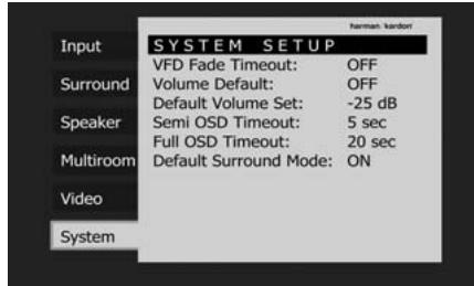
Figure 32
With the SYSTEM SETUP menu on your video display, press the / Navigation Button 14 so that the blue cursor bar is highlighting the VFD Fade Timeout-line. Next, press the Set Button 16, followed by the / Navigation Button 15 37 so that the amount of time that you wish the displays to fade out after a button is pressed is shown.
Once this time is set and the unit returned to normal operation, the displays will remain on for the time period selected whenever a button is pressed on the front panel or remote. After that time they will gradually fade out, with the exception of the lighting surrounding the
Standby/On Switch 3, which remains on to remind you that the AVR is turned on. Note that if the displays have been turned completely off using the Dim Button, as shown on page 46, the Fade function will not operate.
If you wish to make adjustments to other items on the SYSTEM SETUP menu, press the / Navigation Button 14 to place the blue cursor bar on the desired item and press the Set Button 16 to make an adjustment to another menu. If you have completed all adjustments, press the OSD Button 22 to exit the menu system.
Turn On Volume Level
As is the case with most audio/video receivers, when the AVR is turned on, it will always return to the volume setting in effect when the unit was turned off. However, you may prefer to always have the AVR turn on at a specific setting, regardless of what was last in use when the unit was turned off. To change the default condition so that the same volume level is always used at turn-on, you will need to make an adjustment in the SYSTEM SETUP menu. To start the adjustment, press the OSD button 22 to bring the main menu (Figure 1) to the screen. Press the button 14, until the System -tab is highlighted in white. Press the Set button 16 to enter the SYSTEM SETUP menu (Figure 32).
At the SYSTEM SETUP menu make certain that the blue cursor bar is on the Volume Default line by pressing the / buttons 14 as needed. Next, press the Set Button 16, followed by the / buttons 1537 so that the word ON is shown in the video display and press Set 16 to confirm. Next, press the button 14 once so that the blue cursor bar highlights the Default Volume Set line. To set the desired turn-on volume, press the Set Button 16, followed by the / buttons 1537 or hold them pressed until the desired volume level is shown on the Default Volume Set line and press the Set Button 16 to confirm. Note that this setting may NOT be made with the regular volume controls.
NOTE: Since the setting for the turn-on volume cannot be heard while the setting is being made, you may wish to determine the setting before making the adjustment. To do this, listen to any source and adjust the volume to the desired level using the regular volume controls 40. When the desired volume level to be used at turn-on is reached, make a note of the setting as it appears in the lower third of the video screen or in the Main Information Display 28. A typical volume level will appear as a negative number such as -25dB. When making the adjustment, use the buttons 1537 to enter this setting.
Unlike some of the other adjustments in this menu, the turn-on volume default will remain in effect even when the unit is turned off completely, unless it is changed or turned off in this menu.
If you wish to make other adjustments in the menu, press the / Buttons 14 until the on-screen blue cursor bar is highlighting the desired setting. If you have no other adjustments to make, press the OSD Button 22 to exit the menu system.
Semi-OSD Settings
The semi-OSD system places two-line messages at the lower third of the video display screen whenever the Volume, Input Source, Surround mode or tuner frequency of any of the configuration settings are changed. The semi-OSD system is helpful in that enables you to have feedback on any control changes or remote commands using the video display when it is difficult to view the front-panel displays. However, you may occasionally prefer to turn these displays off for a particular listening session. You may also want to adjust the length of time the displays remain on the screen. Both of those options are possible with the AVR.
To turn off the semi-OSD system, you will need to make an adjustment in the SYSTEM SETUP menu (Figure 32). To start the adjustment, press the OSD button to bring the main menu to the screen. Press the Button until the System -tab is highlighted in white. Press the Set Button to enter the SYSTEM SETUP menu.
At the SYSTEM SETUP menu make certain that the blue cursor bar is highlighting the SemiOSD Timeout line by pressing the / buttons 14 as needed. Next, press the Set Button 16, followed by the button 37 so that the word OFF is shown in the video display and press Set 16 to confirm the new setting.
Note that this setting is temporary and will remain active only until it is changed or until the AVR is turned off. Once the unit is turned off, the semi-OSD displays will remain activated, even if they were switched off for the previous listening session.
To change the length of time that the semi-OSD displays remain on the screen, go to the Senti OSD Timeout-line as outlined earlier, and press the Set Button 16. Next, press the Buttons 1537 until the desired time in seconds is displayed and press the Set Button 16 to confirm the new setting. Note that unlike most of the other options in this menu, this is a permanent setting change, and the time-out entry will remain in effect until it is changed, even when the unit is turned off.
If you wish to make other adjustments in the menu, press the / Buttons 14 until the blue cursor bar is highlighting the desired setting. If you have no other adjustments to make, press the OSD Button 22 to exit the menu system.
Full-OSD Time Out Adjustment
The FULLOSD menu system is used to simplify the setup and adjustment of the AVR using a series of on-screen menus. The factory default setting for these menus leaves them on the screen for 20 seconds after a period of inactivity before they disappear from the screen or Time Out. This Time Out is a safety measure to prevent the menu text from burning into the CRTs in your monitor or projector, which might happen if they were left on indefinitely. However, some viewers may prefer a slightly longer or shorter period before the Time Out display.
To change the Full-OSD Time Out, you will need to make an adjustment in the SYSTEM SETUP menu (Figure 32). To start the adjustment, press the OSD button 22 to bring the main menu to the screen. Press the button 14, until the System - tab on the left is highlighted in white. Press the Set Button 16 to enter the SYSTEM SETUP menu.
At the SYSTEM SETUP menu make certain that the blue cursor bar is highlighting the Full OSD Timeout line by pressing the / Buttons 14 as needed. Next, press the Set Button 16, followed by the / buttons 1537 until the desired time is displayed in seconds and press the Set Button 16 to confirm the new setting. Note that unlike most of the other options in this menu, this is a permanent setting change, and the time-out entry will remain in effect until it is changed, even when the unit is turned off.
If you wish to make other adjustments in the menu, press the / Buttons until the blue cursor bar is highlighting the desired setting. If you have no other adjustments to make, press the OSD Button 22 to exit the menu system.
Default Surround Mode
In normal operation, when the AVR senses a Dolby Digital or DTS digital audio data stream, it will automatically switch the appropriate default surround mode, with the AVR responding to the data flags that are encoded on the DVD disc or in the digital video broadcast. In most cases, this is the correct mode, but you may have a particular preference for the mode you wish to hear when Dolby Digital or DTS is present. The AVR allows you to set the unit so that it will either respond to the default or switch to your desired mode.
If you wish to leave the default so that the mode choice encoded in the disc is always used, no further action is needed. Simply leave the setting at the factory default of ON.
To set the unit so that it responds to the last surround mode used when a Dolby Digital or DTS source is playing, press the / Buttons 14 so that the blue cursor bar is highlighting the Default Surround Mode line. Press the Set Button 16, followed by the Buttons 15-37 so that OFF appears, and the setting will change. Press the Set Button 16 again to confirm the new setting. The unit will now use the last mode, not the disc's default for the two digitally encoded data streams.
This setting does not apply to standard PCM digital inputs or to analog sources. In those cases, the unit will always apply the surround or processing mode that was last used for that input.
If you wish to make other adjustments, press the / Buttons until the blue cursor bar is highlighting the desired setting. If you have no other adjustments to make, press the OSD Button to exit the menu system.
Basic Tuner Operation
The AVR 350's tuner is capable of tuning AM, FM and FM Stereo broadcast stations and receiving RDS data. Stations may be tuned manually, or they may be stored as favorite station presets and recalled from a 30 position memory.
Station Selection
- Press the AM/FM Tuner Select button 7 on the remote to select the tuner as an input. The tuner may be selected from the front panel by either pressing the Input Source Selector 15 until the tuner is active or by pressing the Tuner Band Selector 11 at any time.
- Press the AM/FM Tuner Select button or Tuner Band Selector 11 again to switch between AM and FM so that the desired frequency band is selected.
- Press the Tuner Mode button 19 on the remote or hold the Band Selector 11 on the front panel pressed for 3 seconds to select manual or automatic tuning.
When the button is pressed so that A U T 0 appears in the Main Information Display 23 each press of the Tuning Selectors 820 will put the tuner in a scan mode that seeks the next higher or lower frequency station with acceptable signal strength. An AUTO ST TUNED indication will momentarily appear when the station stops at a stereo FM station, and an AUTO TUNED indication will momentarily appear when an AM or monaural FM station is tuned. Press the Tuning buttons again to scan to the next receivable station.
When the button is pressed so that MANUAL appears in the Main Information Display 23 each tap of the Selector will increase or decrease the frequency by one increment. When the tuner receives a strong enough signal for adequate reception, MANUAL TUNED will appear in the Main Information Display 23.
- Stations may also be tuned directly by pressing the Direct button 20, and then pressing the Numeric Keys 18 that correspond to the station's frequency. Note that for entering numbers higher than 100 you need to enter only the "1" rather than "10", the first "0" will be added automatically. The desired station will automatically be tuned after the latest number is entered. If you press an incorrect button while entering a direct frequency, press the Clear button 34 to start over.
NOTE: When the FM reception of a stereo station is weak, audio quality will be increased by switching to Mono mode by pressing the Tuner Mode button 19 on the remote or holding the Band Selector 11 on the front panel so that MANUAL appears momentarily in the Main Information Display 23 and then goes out.
Preset Tuning
Using the remote, up to 30 stations may be stored in the AVR's memory for easy recall using the front panel controls or the remote.
To enter a station into the memory, first tune the station using the steps outlined above. Then:
- Press the Memory button 35 on the remote. Note that two underscore lines will appear in the Main Information Display 28.
- Within five seconds, press the Numeric Keys 13 corresponding to the location where you wish to store this station's frequency. Once entered, the preset number will appear in the Main Information Display 28.
- Repeat the process after tuning any additional stations to be preset.
Recalling Preset Stations
- To manually select a station previously entered in the preset memory, press the Numeric Keys 13 that correspond to the desired station's memory location.
- To manually tune through the list of stored preset stations one by one, press the Preset Stations Selector buttons 13 33 on the front panel or remote.
RDS Operation
The AVR 350 is equipped with RDS (Radio Data System), which brings a wide range of information to FM radio. Now in use in many countries, RDS is a system for transmitting station call signs or network information, a description of station program type, text messages about the station or specifics of a musical selection, and the correct time.
As more FM stations become equipped with RDS capabilities, the AVR will serve as an easy-to-use center for both information and entertainment. This section will help you take maximum advantage of the RDS system.
RDS Tuning
When an FM station is tuned in and it contains RDS data, the AVR will automatically display the station's call sign or other program service in the
Main Information Display 23.
RDS Display Options
The RDS system is capable of transmitting a wide variety of information in addition to the initial station call sign that appears when a station is first tuned. In normal RDS operation the display will indicate the station name, broadcast network or call letters. Pressing the RDS button 1632 enables you to cycle through the various data types in the following sequence:
- The station's call letters (with some private stations other information too).
- The station's frequency (FREQ).
The Program Type (P T Y) as shown in the list below.
NOTE: Many stations do not transmit a specific PTY. The display will show NONE, when such a station is selected and PTY is active.
- A "text" message (Radiotext, RT) containing special information from the broadcast station. Note that this message may scroll across the display to permit messages longer than the eight positions in the display. Depending on signal quality, it may take up to 30 seconds for the text message to appear; in that time, the word TEXT will flash in the Information Display when RT is selected.
- The current time of day (CT). Note that it may take up to two minutes for the time to appear, in that time the word TIME will flash in the information display when CT is selected. Please note that the accuracy of the time data is dependent on the radio station, not the AVR.
Some RDS stations may not include some of these additional features. If the data required for the selected mode is not being transmitted, the Main Information Display 23 will show a N O T Y P E, N O T E X T or N O T I M e message after the individual time out.
In any FM mode the RDS function requires a strong enough signal for proper operation.
Program Search (PTY)
An important feature of RDS is its capability of encoding broadcasts with Program Type (PTY) codes that indicate the type of material being broadcast. The following list shows the abbreviations used to indicate each PTY, along with an explanation of the PTY:
- (RDS ONLY)
- (TRAFFIC)
NEWS: News - AFFAIRS: Current Affairs
- INFO: Infomation
SPORT:Sports
EDUCATE: Educational - DRAMA: Drama
CULTURE:Culture
SCIENCE:Sciencek
VARIED:Varied Speech Programs - P0PM: Popular Music
ROCKM: Rock Music - M·O·R·M.: Middle-of-the-Road Music
- LIGHTM: Classical Music
- CLASSICS: Serious Classical Music
OTHERM: Other Music - WEATHER: Weather Information
FINANCE: Financial Programs - CHILDREN: Children's Programs
SOCIAL A: Social Affairs Programs - RELIGION: Religious Broadcasts
- PHONE IN: Phone-In Programs
- TRAVEL: Travel and Touring
- LEISURE: Leisure and Hobby
JAZZ: Jazz Music
COUNTRY: Country Music
NATIONAL: National Music
- OLDIES: Oldies Music
FOLK M: Folk Music
- DOCUMENT: Documentary Programs
- TEST: Emergency Test
- ALARM: Emergency Broadcast Information
You may search for a specific Program Type (PTY) by following these steps:
- Press the RDS button 1632 until the current PTY is shown in the Main Information Display 28.
- While the PTY is shown, press the Preset Up/Down button 13 or hold them pressed to scroll through the list of available PTY types, as shown above starting with the PTY currently received. To simply search for the next station transmitting any RDS data, use the Preset Up/Down button 18 until RDS ONLY appears in the display.
- Press any of the Tuning Up/Down buttons 102, the tuner begins to scan the FM band upwards or downwards for the first station that has RDS data that matches the desired selection, and acceptable signal strength for quality reception.
- The tuner will make up to one complete scan of the entire FM band for the next station that matches the desired PTY type and has acceptable reception quality. If no such station is found, the display will read NONE for some seconds and the tuner will return to the last FM station in use before the search.
NOTE: Some stations transmit constant traffic information. These stations can be found by selecting TRAFFIC, the option in front of NEWS in the list. The AVR will find the next appropriate station, even if it is not broadcasting traffic information when the search is made.
The AVR 350 is equipped with a powerful remote control that will control not only the receiver's functions, but also most popular brands of audio and video equipment, including CD players, TV sets, cable boxes, VCRs, satellite receivers and other home-theater equipment. Once the AVR's remote is programmed with the codes for the products you own, it is possible to eliminate most other remotes and replace them with the convenience of a single universal remote control.
Programming the Remote with Codes
As shipped from the factory, the remote is fully programmed for all AVR functions, as well as those of most Harman Kardon CD changers, DVD players, CD players and cassette decks as well as the navigation controls for the Apple iPod. In addition, by following one of the methods below, you may program the remote to operate a wide range of devices from other manufacturers.
Direct Code Entry
This method is the easiest way to program your remote to work with different products.
- Use the tables in the separate setup-code guide to determine the three-digit code or codes that match both the product type (e.g., VCR, TV), and the specific brand name. If there is more than one number for a brand, make note of the different choices.
- Turn on the unit you wish to program into the AVR remote.
- Press and hold both the Input Selector 5 for the type of product to be entered (e.g., VCR, TV) and the Mute × button 39 at the same time. When the Program Indicator 3 turns amber and begins flashing, release the buttons. It is important that you begin the next step within 20 seconds.
-
If the unit you wish to program into the AVR remote has a remotable Power on/off function, follow these steps:
a. Point the AVR's remote towards the unit to be programmed, and enter the first three-digit code number using the Numeric buttons 13. If the unit being programmed turns off, the correct code has been entered. Press the Input Selector 5 again, and note that the red light under the Input Selector will flash three times before going dark to confirm the entry.
b. If the product to be programmed does NOT turn off, continue to enter the three-digit code numbers until the equipment turns off. At this point, the correct code has been entered. Press the Input Selector 5 again and note that the red light under the Input Selector will flash three times before going dark to confirm the entry. -
If the Power function of the unit to be programmed cannot be remoted, follow these steps (max. 20 seconds after step 3 above, or else step 3 must be repeated first):
a. Enter the first three-digit code number using the Numeric buttons 18 and press the Input Selector 5 again. Press the remote button of any transport function remotable with the unit, e.g. Pause or Play 26. If the unit being programmed starts that function, the correct code has been entered.
b. If the unit does not start the function whose button was pressed, repeat steps 3 and 5a above with the next three-digit code number listed in the setup code table for that brand and product type, until the unit reacts properly on the transport function transmitted.
6. Try all of the functions on the remote to make certain that the product operates properly. Keep in mind that many manufacturers use a number of different combinations of codes, so it is a good idea to make certain that not only does the Power control work, but that the volume, channel and transport controls work as they should. If functions do not work properly, you may need to use a different remote code.
7. If the unit does not react to any code entered, if the code for your product does not appear in the tables in the separate setup-code guide, or if not all functions operate properly, try programming the remote with the Auto Search Method.
Note on Using the AVR remote with a Harman Kardon CD Recorder.
As shipped from the factory, the remote is programmed for controlling Harman Kardon CD players. It can also control most functions of the Harman Kardon CD-Recorders (see function list on page 58-59) too after the code "002" is entered on the CD Selector button 5 as described above. For returning to the CD player control commands the code "001" must be entered.
Auto-Search Method
If the unit you wish to include in the AVR's remote is not listed in the code tables in the separate setup-code guide or if the code does not seem to operate properly, you may wish to program the correct code using the Auto Search method that follows. Note that the Auto Search method works only with units whose Power functions can be remoted:
- Turn on the product that you wish to include in the AVR remote.
-
Press and hold both the Input Selector 5 for the type of product to be entered (e.g., VCR, TV) and the Mute button at the same time. When the Program Indicator 3 turns amber and begins flashing, release the buttons. It is important that you begin the next step within 20 seconds.
-
To find out if the code for your unit is pre-programmed, point the AVR remote towards the unit to be programmed, and press and hold the button 14. This will send out a series of codes from the remote's built-in data base, with each flash of the red light under the Input Selector 5 indicating that a code has been sent. When the device to be programmed turns off, immediately release the button 14. Note that it may take one minute or more until the right code is found and the unit turns off.
- When the button was not released in time after the unit turned off, the proper code will be "overrun". That's why a function test should be made: Turn the unit on again and, while the Input Selector 5 still lights red, press the button 14 once, than the button 14 once too. When the unit turns off, the right code was found, when not, the code was "overrun". To find the correct, while the Input Selector 5 still lights red, press (not hold pressed) the button 14 repeatedly to step backwards through the codes available and observe the reaction of the unit at each press. As soon as the unit turns off the correct code is found.
- Press the Input Selector ⑤ again, and note that the red light will flash three times before going dark to confirm the entry.
- Try all of the functions on the remote to make certain that the product operates. Keep in mind that many manufacturers use a number of different combinations of codes, and it is a good idea to make certain that not only the Power control works, but the volume, channel and transport controls, as appropriate. If all functions do not work properly, you may need to Auto-Search for a different code, or enter a code via the Direct Code Entry method.
Code Readout
When the code has been entered using the Auto Search method, it is always a good idea to find out the exact code so that it may be easily reentered if necessary. You may also read the codes to verify which device has been programmed to a specific Control Selector button.
- Press and hold both the Input Selector 5 for the device you wish to find the code for and the Mute button 39 at the same time. Note that the Program Indicator 3 will initially turn amber and begin flashing. Release the buttons and begin the next step within 20 seconds.
- Press the Set button 16. The Program Indicator 3 will then blink green in a sequence that corresponds to the three-digit code, with a one-second pause between each digit. Count the number of blinks between each pause to determine the digit of the code. One blink is the number 1, two blinks is the number 2, and so forth. Note that a rapid sequence of three blinks is used to indicate a "0."
Example: One blink, followed by a one-second pause, followed by six blinks, followed by a one-second pause, followed by four blinks indicates that the code has been set to 164.
For future reference enter the Setup Codes for the equipment in your system here:
DVD CD
VID1/VCR VID3/TV
VID2/CBL/SAT
TAPE
VID4
Learning Codes from a Remote
In addition to using codes from the remote's internal code library, the AVR 350's remote is able to "learn" codes from remotes that may not be in the code library. In addition, you may use this function to "learn over" the codes from a preprogrammed device to add functions not included in the preprogrammed codes. To learn or transfer codes from an IR remote to the AVR 350's remote, follow these steps:
- Place the front of the original remote with the code being sent so that it is facing the IR Transmitter Window 2 on the AVR 350 remote "head-to-head." The remotes should be between 2 and 4 cm apart.
- Select the button on the remote that you wish to use as the device selector for the codes about to be entered. This must be any of the Input Selectors 5 or the AVR Selector 6. Note that when new codes are learned with the AVR Selector 6, they may no longer control the AVR 350.
- Press the Input Selector 5 6 button chosen and the Learn Button 44 at the same time. Hold these buttons until the Program/SPL Indicator 3 flashes amber and the light under the device selector button turns red. Release the buttons. It is important that you begin the next step within 20 seconds.
- Press the button on the AVR 350 remote that you wish to program. Note that the Program/SPL Indicator ③ will stop flashing.
Important Note: Codes cannot be taught to all buttons on the remote. The buttons with the following numbers are not learnable (for numbers, see drawing on page 11): 5, 8,
9,12,19,25,27,29,35,39,41 44. In these cases the Program/SPL
Indicator 3 keeps flashing after the button was released.
- As long as the Program/SPL Indicator ③ is on steadily (for five seconds), press and hold the button on the original remote that you wish to "teach" into the AVR 350 remote. If you pressed the button too late or no command was received within five seconds, the Program/SPL
Indicator 3 will flash red three times and then amber, then simply repeat step four. When the Program/SPL Indicator 3 turns green, release the button on the original remote. Note that the Program Indicator will then begin to flash amber again.
NOTE: If the Program/SPL Indicator ③ turns red steadily during Step 5, the program- ming was not successful. Repeat the steps to see if the code will "take." If the indicator keeps flashing red in step 5, this code cannot be taught.
- Repeat steps 4 though 5 for each button on the source remote that you wish to transfer to the AVR 350 remote.
- Once all codes have been transferred from the original source remote to the AVR 350 remote, press the Learn button 4. This will turn off all LEDs and turn off the learning mode.
- Repeat Steps 1 through 7 for any additional remotes you wish to "teach" into the AVR 350 Remote.
Erasing Learned Codes
The AVR 350's remote allows you to remove or erase the code learned into a single button for a single device, to remove or erase all the codes that have been learned for a single device, or to erase all commands that have been learned to all devices.
To erase a single learned code from within a single device's settings, follow these steps:
-
Press and hold both the Input Selector 5 6 within which the individual button to be erased has been programmed and the Learn button 44.
-
When the red LED under the Input Selector turns red and the Program/SPL Indicator ③ flashes amber, release the buttons.
- Press and release the Input Selector 5 6 again for the device within which the individual button to be erased has been programmed.
- Press the 7 button 13 three times.
- Press and release the individual button for which the code is to be erased. The Program/SPL Indicator ③ will blink green two times and then return to amber.
- To erase other buttons within the same device, press them as noted in Step 5.
- When all buttons to be erased have been pressed, press the Learn button 44 to complete the process.
To erase all codes within a single device, follow these steps:
- Press and hold both the Input Selector 5 6 for which you wish to erase the codes and the Learn button 44.
- When the red LED under the Input Selector turns red and the Program/SPL Indicator ③ flashes amber, release the buttons.
- Press and release the same Input Selector 5 6 again for the device whose codes you wish to erase.
- Press the 8 button 13 three times.
- The Program/SPL Indicator ③ will turn off, the red light under the Input Selector will flash on and off once and the Program/SPL Indicator ③ will flash green three times to indicate that the codes have been erased.
To erase all codes that have been programmed to all devices in the remote, follow these steps:
- Press any Input Selector 5 6 and also the Learn button 44
- When the red LED under the Input Selector turns red and the Program/SPL Indicator ③ flashes amber, release the buttons.
- Press and release the same Input Selector 56 again.
- Press the 9 button 13 three times.
- The Program/SPL Indicator ③ will turn off, the red light under the Input Selector will flash on and off once and the Program/SPL Indicator ③ will flash green three times after some seconds to indicate that the codes have been erased.
Macro Programming
Macros enable you to easily repeat frequently used combinations of commands with the press of a single button on the AVR's remote control. Once programmed, a macro will send out up to 19 different remote codes in a pre-determined sequential order enabling you to automate the process of turning on your system, changing devices, or other common tasks. The AVR's remote can store up to five separate macro command sequences, one that is associated with the Power On button 4, and four more that are accessed by pressing the Macro buttons 31.
- To start programming a macro, press the Mute button 39 and the Macro button 31 to be programmed or the Power-On button 4 at the same time. Note that the latest selected Input Selector will light red, and the Program Indicator 3 will flash amber.
- Enter the steps for the macro sequence by pressing the button for the actual command step. Although the macro may contain up to 19 steps, each button press, including those used to change devices, counts as a step. The Program Indicator will flash green twice to confirm each button press as you enter commands.
NOTE: While entering commands for Power On of any device during a macro sequence, press the Mute button 39. DO NOT press the Power ON button 4.
- Remember to press the appropriate Input Selector button ⑤ before functions are changed to another device. This is also needed for the AVR Selector button ⑥ itself, as long as it's not lit red and AVR functions shall be programmed.
- When all the steps have been entered, press the Sleep button to enter the commands. The red light under the Input Selector will blink and then turn off and the Program Indicator will flash green twice to confirm the macro to be programmed.
Example: To program the Macro 1 31 button so that it turns on the AVR, TV and a Sat-Receiver, follow these steps:
- Press the Macro 1 button 31 and Mute 39 buttons at the same time and then release them.
Note that the Program Indicator will flash amber. - Press the AVR Selector 6
- Press the Mute 39 button to store the AVR's power on command.
- Press the VID 2 Input Selector button to indicate the next command is for "TV".
-
Press the Mute 39 button to store the TV Power On Command.
-
Press the VID 3 Input Selector button to indicate the next command is for "Sat-Receiver".
-
Press the Mute 39 button to store the Sat-Receiver Power On command.
- Press the Sleep/Channel Up button to complete the process and store the macro sequence.
After following these steps, each time you press the Macro 1 button 31, the remote will send all Power On commands.
Erasing Macro Commands
To remove the commands that have been programmed into one of the Macro buttons, follow these steps:
- Press the Mute button 39 and the Macro button 31 that contains the commands you wish to erase.
- Note that the Program Indicator 3 will flash amber, and the red LED under the Input Selector 5 6 last used will turn on.
- Within ten seconds, press the Surround Mode Selector/Channel Down button 11.
- The red LED under the Selector will go out, and the Program Indicator ③ will turn green and flash three times before it goes out.
- When the Program Indicator 3 goes out, the Macro has been erased.
Programmed Device Functions
Once the AVR's remote has been programmed for the codes of other devices, press the appropriate Input Selector 5 to change the remote from control over the AVR to the additional product. When you press any of these buttons, it will briefly flash in red to indicate that you have changed the device being controlled.
When operating a device other than the AVR, the controls may not correspond exactly to the function printed on the remote or button. Some commands, such as the volume control, are the same as they are with the AVR. Other buttons will change their function so that they correspond to a secondary label on the remote. For example, the Sleep and Surround mode selector buttons also function as the Channel Up and Channel Down buttons when operating most TV sets, VCRs or Sat-Receivers.
For some products, however, the function of a particular button does not follow the command printed on the remote. In order to see which function a button controls, consult the Function List tables printed on page 58-59. To use those tables, first check the type of device being controlled (e.g., TV, VCR). Next, look at the remote control diagram on page 58. Note that each button has a number on it.
To find out what function a particular button has for a specific device, find the button number on the Function List and then look in the column for the device you are controlling. For example, button number 45 is the "Direct" button for the AVR, but it is the "Favorite" button for many cable television boxes and satellite receivers. Button number 31 is the Delay button for the AVR, but the Open/Close button for CD players.
Note that the numbers used to describe the button functions above and on page 58 for the purposes of describing how a button operates are a different set of numbers than those used in the rest of this manual to describe the button functions for the AVR.
Notes on Using the AVR
Remote With Other Devices.
- Manufacturers may use different code sets for the same product category. For that reason, it is important that you check to see if the code set you have entered operates as many controls as possible. If it appears that only a few functions operate, check to see if another code set will work with more buttons.
- Depending on the brand and product type used the functions listed in the Function List tables may not correspond with the function the unit reacts on the command. In these cases it's a good idea to edit the reaction of the unit into the corresponding line of the table or to set up a separate list.
- When a button is pressed on the AVR remote, the red light under the Input Selector 5 6 for the product being operated should flash briefly. If the Device Control Selector flashes for some but not all buttons for a particular product, it does NOT indicate a problem with the remote, but rather that no function is programmed for the button being pushed.
Volume Punch-Through
The AVR's remote may be programmed to operate the Volume Control 40 and the Mute 39 from either the TV or the AVR in conjunction with any of the devices controlled by the remote. For example, since the AVR will likely be used as the sound system for TV viewing, you may wish to have the AVR's volume activated although the remote is set to run the TV. Either the AVR or TV volume control may be associated with any of the remote's devices.
To program the remote for Volume PunchThrough, follow these steps:
- Press the Input Selector 5 for the unit you wish to have associated with the volume control and the Mute button 39 at the same time until the red light illuminates under the Input Selector 5 and note that the Program Indicator 3 will flash amber.
- Press the Volume Up button 40 and note that the Program Indicator 3 will stop flashing and stay amber.
- Press either the AVR Selector 6 or the Input Selector 5, depending on which system's volume control you wish to have attached for the punch-through mode. The Program Indicator 3 will blink green three times and then go out to confirm the data entry.
Example: To have the AVR's volume control activated even though the remote is set to control the TV, first press the Video/TV Input Selector 5 and the Mute button 39 at the same time. Next, press the Volume Up button 40, followed by the AVR Input Selector 6.
NOTE: Should you wish to return the remote to the original configuration after entering a Volume Punch-Through, you will need to repeat the steps shown above. However, press the same Input Selector in steps one and three.
Channel Control Punch-Through
The AVR's remote may be programmed to operate so that the channel control function, performed with the Sleep 10 and Surround 11 buttons, for either the TV, cable or satellite receiver used in your system may be used in conjunction with one of the other devices controlled by the remote. For example, while using and controlling the VCR, you may wish to change channels on a cable box or satellite receiver without having to change the device selected by the AVR or the remote. To program the remote for Channel Control Punch-Through, follow these steps:
- Press the Input Selector button ⑤ for the device you wish to have the channel control associated with and the Mute button ③ at the same time until the red light illuminates under the Input Selector ⑤ and the Program Indicator ③ flashes amber.
- Press the Volume Down button 40. The Program Indicator 3 will stop flashing and stay amber.
- Press and release the AVR 6 or Input Selector button 5 for the device that will be used to change the channels. The Program Indicator 3 will blink green three times and then go out to confirm the data entry.
Example: To control the channels using your TV while the remote is set to control the VCR, first press the VID 1/VCR Input Selector button and the Mute button at the same time. Next, release them and press the Volume Down button, followed by the same Input Selector button.
NOTE: To remove the Channel Control Punch-Through and return the remote to its original configuration, repeat the steps shown in the example above. However, press the same Input Selector in Steps 1 and 3.
Transport Control Punch-Through
The AVR's remote may be programmed to operate so that the Transport Control Functions (Play, Stop, Fast Forward, Rewind, Pause and Record) for a VCR, DVD or CD will operate in conjunction with one of the other devices controlled by the remote. For example, while using and controlling the TV, you may wish to start or stop your VCR or DVD without having to change the device selected by the AVR or the remote. To program the remote for Transport Control Punch-Through, follow these steps:
-
Press the Input Selector 5 for the device you wish to have the channel control associated with and the Mute button 39 at the same time until the red light illuminates, under the Input Selector 5 and the Program Indicator 3 flashes amber.
-
Press the Play button 26.The Program Indicator 3 will stop flashing and stay amber.
-
Press and release the AVR 6 or Input Selector button 5 for the device that will be used to change the channels. The Program Indicator 3 will blink green three times and then go out to confirm the data entry.
Example: To control the transport of a CD player while the remote is set to control the TV, press the VID 2/TV Input Selector button 5 and the Mute button 39 at the same time. Next, release them and press the Play button 25, followed by the CD Input Selector button 5.
NOTE: To remove the Channel Control Punch-Through and return the remote to its original configuration, repeat the steps shown in the example above. However, press the same Input Selector in Steps 1 and 3.
NOTE: Before programming the remote for Volume, Channel or Transport Punch-Through, make certain that any programming needed for the specific TV, CD, DVD, Cable or Satellite Receivers has been completed.
Resetting the Remote Memory
As you add components to your home-theater system, occasionally you may wish to totally reprogram the remote control without the confusion of any commands, macros or "Punch-Through" programming that you may have done. To do this, it is possible to reset the remote to the original factory defaults and command codes by following these steps. Note, however, that once the remote is reset, all commands or codes that you have entered will be erased and will need to be re-entered:
- Press any of the Input Selector buttons 5 and the "0" button 13 at the same time until the Program Indicator 3 begins to flash amber.
- Press the "3" button 13 three times.
- The red LED under the Input Selector ⑤ will go out and the Program Indicator ③ will stop flashing and turn green.
- The Program Indicator ③ will remain green until the remote is reset. Note that this may take a while, depending on how many commands are in the memory and need to be erased.
- When the Program Indicator 3 goes out, the remote has been reset to the factory settings.
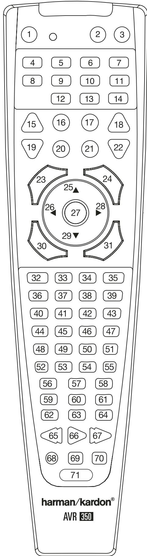
| No. | Button Name | AVR Function | DVD | CD/CD-R | Tape |
| 1 | Power On | Power On | Power On | Power On | Power On |
| 2 | Power Off | Power Off | Power Off | Power Off | Power Off |
| 3 | Mute | Mute | Mute | Mute | Mute |
| 4 | AVR | AVR Select | AVR Select | AVR Select | AVR Select |
| 5 | DVD/CD | DVD Input SelectCD Input Select | DVD SelectCD Select | DVD SelectCD Select | DVD SelectCD Select |
| 6 | Tape/bridgese | Tape SelectThe Bridge (DMP) Select | Tape SelectThe Bridge (DMP) Select | Tape SelectThe Bridge (DMP) Select | Tape SelectThe Bridge (DMP) Select |
| 7 | HDMI1/HMI2 | HDMI1 SelectHMI2 Select | HDMI1 SelectHMI2 Select | HMI1 SelectHMI2 Select | HMI1 SelectHMI2 Select |
| 8 | VID 1 (VCR) | Video 1 Select | VCR Select | VCR Select | VCR Select |
| 9 | VID 2 (CBL/SAT) | Video 2 Select | CBL/SAT Select | CBL/SAT Select | CBL/SAT Select |
| 10 | VID 3 (TV) | Video 3 Select | TV Select | TV Select | TV Select |
| 11 | VID 4 | Video 4 Select | Video 4 Select | Video 4 Select | Video 4 Select |
| 12 | AM/FM | Tuner Select | Tuner Select | Tuner Select | Tuner Select |
| 13 | 6/8 Ch. Select | 6/8 Ch Input Select | 6/8 Ch Input Select | 6/8 Ch Input Select | 6/8 Ch Input Select |
| 14 | Learn | Learn | Learn | Learn | Learn |
| 15 | Sleep/CH+ | Sleep | |||
| 16 | Test Tone | Test Tone | |||
| 17 | T/V | TV/DVD or V. OFF | Input Select | ||
| 18 | Volume Up | Volume Up | Volume Up | Volume Up | |
| 19 | Surround/CH- | DSP Surround Mode Select | Disc menu or Title | CDR Select | |
| 20 | OSD | OSD | Program | ||
| 21 | M-ROOM | M-ROOM | HD Mode | ||
| 22 | Volume Down | Volume Down | Volume Down | Volume Down | |
| 23 | Channel/Guide | Channel Trim | Title or Disc Menu | Continuos Play | |
| 24 | Speaker/Menu | Speaker Setup | Menu or Setup | Intro Scan | |
| 25 | ▲ | Move/Adjust Up | Up | ||
| 26 | ← | Move/Adjust Left | Left | ||
| 27 | Set | Set | Enter | ||
| 28 | ▶ | Move/Adjust Right | Right | ||
| 29 | ▼ | Move/Adjust Down | Down | ||
| 30 | Digital/Exit | Digital Input Select | Open/Close | ||
| 31 | Delay/Prev. Ch. | Delay Adjust | Return or Status | Open/Close | |
| 32 | 1 | 1 | 1 | 1 | |
| 33 | 2 | 2 | 2 | 2 | |
| 34 | 3 | 3 | 3 | 3 | |
| 35 | 4 | 4 | 4 | 4 | |
| 36 | 5 | 5 | 5 | 5 | |
| 37 | 6 | 6 | 6 | 6 | |
| 38 | 7 | 7 | 7 | 7 | |
| 39 | 8 | 8 | 8 | 8 | |
| 40 | Tun-M | Tuner Mode | Chapter+ or Zoom | Repeat | |
| 41 | 9 | 9 | 9 | 9 | |
| 42 | 0 | 0 | 0 | 0 | |
| 43 | Memory | Memory | Audio or Playlist | Time | |
| 44 | Tuning Up | Tuning Up | Next Chapter | Track Direct | |
| 45 | Direct | Direct Tuner Entry | Angle | Random Play | |
| 46 | Clear | Clear | Clear | Clear | |
| 47 | Preset Up | Preset Tune Up | Slow Forward | +10 | |
| 48 | Tuning Down | Tune Down | Prev Chapter | Track Increment | |
| 49 | Tone | Tone Mode | Program | ||
| 50 | RDS | RDS | |||
| 51 | Preset Down | Preset Down | Slow Rev | ||
| 52 | M1 | Macro 1 | Macro 1 | Macro 1 | Macro 1 |
| 53 | M2 | Macro 2 | Macro 2 | Macro 2 | Macro 2 |
| 54 | M3 | Macro 3 | Macro 3 | Macro 3 | Macro 3 |
| 55 | M4 | Macro 4 | Macro 4 | Macro 4 | Macro 4 |
| 56 | Dolby Surround | Dolby Modes | |||
| 57 | DTS SURR | DTS Digital Modes | |||
| 58 | DTS Neo:6 | DTS Neo:6 Select | |||
| 59 | Night | Night Mode Select | Subtitle On/Off | CDP Select | |
| 60 | Logic 7 | Logic 7 Select | |||
| 61 | Stereo | Stereo Mode Select | |||
| 62 | Skip Down | Skip - (DVD) | Step - | Skip - | |
| 63 | Skip Up | Skip + (DVD) | Step + | Skip + | |
| 64 | Dim | Dimmer | |||
| 65 | Rewind | R. Search (DVD) | R. Search | R. Search | Rewind |
| 66 | Play | Play (DVD) | Play | Play | R. Play/F. Play |
| 67 | Fast Forward | F. Search (DVD) | F. Search | F. Search | Fast Fwd |
| 68 | Record | Record | Record/Pause | ||
| 69 | Stop | Stop (DVD) | Stop | Stop | Stop |
| 70 | Pause | Pause (DVD) | Pause | Pause | |
| 71 | Light | Light | Light | Light |
| No. | Button Name | VCR (VID 3) | TiVo (VID 1) | CBL (VID 2) | SAT (VID 2) | TV (VID 1) | Bridge(DMP) | HDMI 1/2 |
| 1 | Power On | Power On | Power On | Power On | Power On | Power On | ||
| 2 | Power Off | Power Off | Power Off | Power Off | Power Off | Power Off | ||
| 3 | Mute | Mute | Mute | Mute | Mute | Mute | Mute | |
| 4 | AVR | AVR Select | AVR Select | AVR Select | AVR Select | AVR Select | AVR Select | AVR Select |
| 5 | DVD CD | DVD Select CD Select | DVD Select CD Select | DVD Select CD Select | DVD Select CD Select | DVD Select CD Select | DVD Select CD Select | DVD Input Select CD Input Select |
| 6 | Tape/ Bridge | Tape Select The Bridge (DMP) Select | Tape Select The Bridge (DMP) Select | Tape Select The Bridge (DMP) Select | Tape Select The Bridge (DMP) Select | Tape Select The Bridge (DMP) Select | Tape Select The Bridge (DMP) Select | Tape Select The Bridge (DMP) Select |
| 7 | HDMI1/HDMI2 | HDMI1 Select HDMI2 Select | HDMI1 Select HDMI2 Select | HDMI1 Select HDMI2 Select | HDMI1 Select HDMI2 Select | HDMI1 Select HDMI2 Select | HDMI1 Select HDMI2 Select | HDMI1 Select HDMI2 Select |
| 8 | VID 1 (VCR) | VCR Select | VCR Select | VCR Select | VCR Select | VCR Select | VCR Select | VCR Select |
| 9 | VID 2 (CBL/SAT) | CBL/SAT Select | CBL/SAT Select | CBL Select | SAT Select | CBL/SAT Select | CBL/SAT Select | CBL/SAT Select |
| 10 | VID 3 (TV) | TV Select | TV Select | TV Select | TV Select | TV Select | TV Select | TV Select |
| 11 | VID 4 | Video 4 Select | Video 4 Select | Video 4 Select | Video 4 Select | Video 4 Select | Video 4 Select | Video 4 Select |
| 12 | AM/FM | Tuner Select | Tuner Select | Tuner Select | Tuner Select | Tuner Select | Tuner Select | Tuner Select |
| 13 | 6/8 Ch. Select | 6/8 Ch Input Select | 6/8 Ch Input Select | 6/8 Ch Input Select | 6/8 Ch Input Select | 6/8 Ch Input Select | 6/8 Ch Input Select | 6/8 Ch Input Select |
| 14 | Learn | Learn | Learn | Learn | Learn | Learn | Learn | Learn |
| 15 | Sleep/CH+ | Channel + | Channel + | Channel + | Channel + | Channel + | Channel + | |
| 16 | Test Tone | |||||||
| 17 | T/V | TV/VCR | TV Input | TV/CBL | TV/SAT | TV/VCR | TV/Video | |
| 18 | Volume Up | Volume Up | Volume Up | Volume Up | Volume Up | Volume Up | ||
| 19 | Surround/CH- | Channel - | Channel - | Channel - | Channel - | Channel - | Channel - | |
| 20 | OSD | OSD | Live TV | OSD | OSD | OSD | OSD | |
| 21 | M-ROOM | |||||||
| 22 | Volume Down | Volume Down | Volume Down | Volume Down | Volume Down | Volume Down | ||
| 23 | Channel/Guide | Guide | Info/Guide | Info/Guide | Guide | |||
| 24 | Speaker/Menu | Menu | Menu | Menu | Menu | Menu | Menu | Menu |
| 25 | ▲ | Up | Up | Up | Up | Up | Up | |
| 26 | ← | Left | Left | Left | Left | Left | Scroll - | Left |
| 27 | Set | Enter | Select | Enter | Enter | Enter | Select | Set/Enter |
| 28 | ▶ | Right | Right | Right | Right | Right | Scroll + | Right |
| 29 | ▼ | Down | Down | Down | Down | Down | Down | |
| 30 | Digital/Exit | Return/Exit | ||||||
| 31 | Delay/Prev. Ch. | Prev Channel | Prev Channel | Prev Channel | Prev Channel | |||
| 32 | 1 | 1 | 1 | 1 | 1 | 1 | 1 | |
| 33 | 2 | 2 | 2 | 2 | 2 | 2 | 2 | |
| 34 | 3 | 3 | 3 | 3 | 3 | 3 | 3 | |
| 35 | 4 | 4 | 4 | 4 | 4 | 4 | 4 | |
| 36 | 5 | 5 | 5 | 5 | 5 | 5 | 5 | |
| 37 | 6 | 6 | 6 | 6 | 6 | 6 | 6 | |
| 38 | 7 | 7 | 7 | 7 | 7 | 7 | 7 | |
| 39 | 8 | 8 | 8 | 8 | 8 | 8 | 8 | |
| 40 | Tun-M | |||||||
| 41 | 9 | 9 | 9 | 9 | 9 | 9 | 9 | |
| 42 | 0 | 0 | 0 | 0 | 0 | 0 | 0 | |
| 43 | Memory | |||||||
| 44 | Tune Up | Cancel | Cancel | Sleep | ||||
| 45 | Direct | FAV/Angle | FAV | FAV/Angle | ||||
| 46 | Clear | Clear | Clear | Next | ||||
| 47 | Preset Up | Alt | ||||||
| 48 | Tune Down | |||||||
| 49 | Tone | |||||||
| 50 | RDS | |||||||
| 51 | Preset Down | |||||||
| 52 | M1 | Macro 1 | Macro 1 | Macro 1 | Macro 1 | Macro 1 | Macro 1 | |
| 53 | M2 | Macro 2 | Macro 2 | Macro 2 | Macro 2 | Macro 2 | Macro 2 | |
| 54 | M3 | Macro 3 | Macro 3 | Macro 3 | Macro 3 | Macro 3 | Macro 3 | |
| 55 | M4 | Macro 4 | Macro 4 | Macro 4 | Macro 4 | Macro 4 | Macro 4 | |
| 56 | Dolby Surround | |||||||
| 57 | DTS SURR | |||||||
| 58 | DTS Neo:6 | |||||||
| 59 | Night | |||||||
| 60 | Logic 7 | |||||||
| 61 | Stereo | |||||||
| 62 | Skip Down | Scan - | Thumbs Down | Skip - (DVD) | Skip - (DVD) | Skip - (DVD) | ||
| 63 | Skip Up | Scan + | Thumbs Up | Skip + (DVD) | Skip + (DVD) | Skip + (DVD) | ||
| 64 | Dim | |||||||
| 65 | Rewind | Rewind | R. Search | R. Search (DVD) | R. Search (DVD) | R. Search (DVD) | Skip - / R. Search | R. Search |
| 66 | Play | Play | Play | Play (DVD) | Play (DVD) | Play (DVD) | Play | Play |
| 67 | Fast Forward | Fast Fwd | F. Search | F. Search (DVD) | F. Search (DVD) | F. Search (DVD) | Skip + / F. Search | F. Search |
| 68 | Record | Record | Record | Record | ||||
| 69 | Stop | Stop | Slow | Stop (DVD) | Stop (DVD) | Stop (DVD) | Stop | |
| 70 | Pause | Pause | Pause | Pause (DVD) | Pause (DVD) | Pause (DVD) | Pause | Pause |
| 71 | Light | Light | Light | Light | Light | Light | Light | Light |
Troubleshooting Guide
| SYMPTOM | CAUSE | SOLUTION |
| Unit does not function when Main Power Switch 1 is pushed | • No AC Power | • Make certain AC power cord is plugged into a live outlet • Check to see if outlet is switch controlled |
| Display lights, but no sound or picture | • Intermittent input connections • Mute is on • Volume control is down | • Make certain that all input and speaker connections are secure • Press Mute button 39 • Turn up volume control |
| No sound from any speaker; light around Power switch 2 is red | • Amplifier is in protection mode due to possible short • Amplifier is in protection mode due to internal problems | • Check speaker-wire connections for shorts at receiver and speaker ends • Contact your local Harman Kardon service depot |
| No sound from surround or center speakers | • Incorrect surround mode • Input is mono • Incorrect configuration • Stereo or Mono program material | • Select a mode other than Stereo • There is no surround information from mono sources (except with Theater and Hall surround modes) • Check speaker mode configuration • Some surround modes may not create rear-channel information from nonencoded programs |
| Unit does not respond to remote commands | • Weak batteries in remote • Wrong device selected • Remote sensor 24 is obscured | • Change remote batteries • Press the AVR Selector 6 • Make certain front-panel sensor is visible to remote or connect remote sensor |
| Intermittent buzzing in tuner | • Local interference | • Move unit or antenna away from computers, fluorescent lights, motors or other electrical appliances |
| Letters flash in the Channel Indicator Display 14 and Digital Audio stops | • Digital audio feed paused | • Resume play for DVD • Check that Digital Signal is fed to the Digital Input selected |
Processor Reset
In the rare case where the unit's operation or the displays seem abnormal, the cause may involve the erratic operation of the system's memory or microprocessor.
To correct this problem, first unplug the unit from the AC wall outlet and wait at least three minutes. After the pause, reconnect the AC power cord and check the unit's operation. If the system still malfunctions, a system reset may clear the problem.
To clear the AVR's entire system memory including tuner presets, output level settings, delay times and speaker configuration data, first put the unit in Standby by pressing the System Power Control button 2. Next press and hold the Tone Mode button 8 for three seconds.
The unit will turn on automatically. Note that once you have cleared the memory in this manner, it is necessary to re-establish all system configuration settings and tuner presets.
NOTE: Resetting the processor will erase any configuration settings you have made for speakers, output levels, surround modes, digital input assignments as well as the tuner presets. After a reset the unit will be returned to the factory presets, and all settings for these items must be reentered.
If the system is still operating incorrectly, there may have been an electronic discharge or severe AC line interference that has corrupted the memory or microprocessor.
If these steps do not solve the problem, consult an authorized Harman Kardon service depot.
Audio Section
Stereo Mode
Continuous Average Power (FTC)
70 Watts per channel, 20Hz-20kHz
@ < 0.07% THD, both channels driven into 8 ohms
7 Channel Surround Modes
Power Per Individual Channel
Front L&R channels:
55 Watts per channel,
@ < 0.07% THD, 20Hz-20kHz into 8 ohms
Center channel:
55 Watts, @ < 0.07% THD, 20Hz-20kHz into 8 ohms
Surround (L & R Side, Back) channels:
55 Watts per channel,
@ < 0.07% THD, 20Hz-20kHz into 8 ohms
Input Sensitivity/Impedance
Linear (High Level) 200mV/47kohms
Signal-to-Noise Ratio (IHF-A) 100dB
Surround System Adjacent Channel Separation
Analog Decoding 40dB
(Pro Logic, etc.)
Dolby Digital (AC-3) 55dB
DTS 55dB
Frequency Response
@ 1W(+0dB, -3dB) 10Hz-130kHz
High Instantaneous
Current Capability (HCC) ±35 Amps
Transient Intermodulation
Distortion (TIM) Unmeasurable
Rise Time 16 μsec
Slew Rate 40V/μsec**
This product incorporates copyright protection technology that is protected by method claims of certain U.S. patents and other intellectual property rights owned by Macrovision Corporation and other rights owners. Use of this copyright protection technology must be authorized by Macrovision Corporation, and is intended for home and other limited viewing uses only unless otherwise authorized by Macrovision Corporation. Reverse engineering or disassembly is prohibited.
FM Tuner Section
Frequency Range 87.5-108MHz
Useable Sensitivity IHF 1.3 V / 13.2dBf
Signal-to-Noise Ratio Mono/Stereo: 70/68dB (DIN)
Distortion Mono/Stereo: 0.2 / 0.3%
Stereo Separation 40dB @ 1kHz
Selectivity ±400kHz: 70dB
Image Rejection 80dB
IF Rejection 90dB
AM Tuner Section
Frequency Range 522-1620kHz
Signal-to-Noise Ratio 45dB
Usable Sensitivity Loop: 500 V
Distortion 1kHz, 50% Mod: 0.8%
Selectivity ±10kHz: 30dB
Video Section
Video Format PAL/NTSC
Input Level/Impedance 1Vp-p/75 ohms
Output Level/Impedance 1Vp-p/75 ohms
Video Frequency Response
(Composite and S-Video)
Video Frequency
Response (Component) 10Hz-100MHz (-3dB)
General
Power Requirement AC 220-240V/50Hz
Power Consumption 118W idle, 890W maximum
(7 channels driven)
Dimensions (Max)
Width 440mm
Height 165mm
Depth 382mm
Weight 13.9 kg
Depth measurement includes knobs, buttons and terminal connections.
Height measurement includes feet and chassis.
All features and specifications are subject to change without notice.
Harman Kardon, The Bridge Bridge and Logic 7 are registered trademarks of
Harman International Industries, Incorporated.
"IIIEzSet/EQ" is a trademark of Harman International Industries, Inc.
*Manufactured under license from Dolby Laboratories.
"Dolby," "Pro Logic" and the Double-D symbol are
trademarks of Dolby Laboratories.
"DTS", "DTS ES", "Neo:6" and "96/24" are trademarks of DTS, Inc.
SA-CD is a trademark of Sony Electronics, Inc.
Blu-ray Disc is a trademark of the Blu-ray Disc Association.
Apple and iPod are registered trademarks of Apple Computer, Inc.
Cirrus is a registered trademark of Cirrus Logic Corp.
**Without input anti slewing and output isolation networks.
A-BUS and A-BUS/READY ^® Ready are registered trademarks of Leisure Tech Electronics Pty Ltd Australia.
Faroudja and DCDi by Faroudja are trademarks of Genesis Microchip, Inc.
HD-DVD is a trademark of the DVD Format/Logo Licensing Corporation (DVD FLLC).
HDMI, the HDMI logo and High-Definition Multimedia Interface are trademarks or registered trademarks of HDMI Licensing, LLC.
Appendix - Default settings, worksheets, remote product codes
Table A1 – Source Input Setting Defaults
| Source | DVD | HDMI 1 | HDMI 2 | Video 1 | Video 2 | Video 3 | Video 4 | The Bridge/DMP | CD | Tape | Tuner | 6-/8-Channel |
| Title | INT.TUNER | |||||||||||
| Video Input | Comp V 1 | HDMI 1 | HDMI 2 | Comp V 2 | Comp V 3 | Composite | Composite | The Bridge/DMP | Comp V 1 | Comp V 1 | Comp V 1 | Comp V 1 |
| Audio Input | Coax 1 | HDMI 1 | HDMI 2 | Analog | Optical 1 | Analog | Analog (The Bridge/DMP) | Analog | Analog | Analog (Tuner) | Analog (6-/8-Channel) | Analog |
| Auto Poll | On | Off | Off | On | On | On | On | Off | On | On | Off | Off |
| Surround Mode† | Logic 7 7CH Music | Logic 7 7CH Music | Logic 7 7CH Music | Logic 7 7CH Music | Logic 7 7CH Music | Logic 7 7CH Music | Logic 7 7CH Music | Logic 7 7CH Music | Logic 7 7CH Music | Logic 7 7CH Music | Logic 7 7CH Music | Logic 7 7CH Music |
† The default shown is the preferred surround mode for PCM and Analog audio sources.
Table A2 - Speaker/Channel Setting Defaults
| Source | DVD | HDMI 1 | HDMI 2 | Video 1 | Video 2 | Video 3 | Video 4 | The Bridge /DMP | CD | Tape | Tuner | 6-/8-Channel |
| Bass Manager: Global | ||||||||||||
| Left/Right Speaker Size | Small | Small | Small | Small | Small | Small | Small | Small | Small | Small | Small | Large |
| Center Speaker Size | Small | Small | Small | Small | Small | Small | Small | Small | Small | Small | Small | Large |
| Surround Speaker Size | Small | Small | Small | Small | Small | Small | Small | Small | Small | Small | Small | Large |
| Surround Back Speaker Size | Small | Small | Small | Small | Small | Small | Small | Small | Small | Small | Small | Large |
| Subwoofer | Sub | Sub | Sub | Sub | Sub | Sub | Sub | Sub | Sub | Sub | Sub | Sub |
| Left/Right Speaker Crossover | 100Hz | 100Hz | 100Hz | 100Hz | 100Hz | 100Hz | 100Hz | 100Hz | 100Hz | 100Hz | 100Hz | N/A |
| Center Speaker Crossover | 100Hz | 100Hz | 100Hz | 100Hz | 100Hz | 100Hz | 100Hz | 100Hz | 100Hz | 100Hz | 100Hz | N/A |
| Surround Speaker Crossover | 100Hz | 100Hz | 100Hz | 100Hz | 100Hz | 100Hz | 100Hz | 100Hz | 100Hz | 100Hz | 100Hz | N/A |
| Subwoofer Crossover | Left/Right | Left/Right | Left/Right | Left/Right | Left/Right | Left/Right | Left/Right | Left/Right | Left/Right | Left/Right | Left/Right | N/A |
Table A3 - Delay Setting Defaults
| Speaker Position | Distance From Speaker to Listening Position | Your Delay Settings |
| Front Left | 3.0 meters | |
| Center | 3.0 meters | |
| Front Right | 3.0 meters | |
| Surround Right | 3.0 meters | |
| Surround Left | 3.0 meters | |
| Subwoofer | 3.0 meters | |
| AV Sync Delay | 0mS |
Table A4 – Source Input Settings
| Source | DVD | HDMI 1 | HDMI 2 | Video 1 | Video 2 | Video 3 | Video 4 | The Bridge/DMP | CD | Tape | Tuner | 6-/8-Channel |
| Title | ||||||||||||
| Video Input | ||||||||||||
| Audio Input | The Bridge/DMP | Tuner | 6-Channel | |||||||||
| Auto Poll | --- | --- | --- | |||||||||
| Surround Mode | ||||||||||||
| Tone Mode | ||||||||||||
| Bass | ||||||||||||
| Treble |
Table A5 - Speaker/Channel Settings
| Source | DVD | HDMI 1 | HDMI 2 | Video 1 | Video 2 | Video 3 | Video 4 | The Bridge/DMP | CD | Tape | Tuner | 6-/8-Channel++ |
| Left/Right Speaker Size | N/A | |||||||||||
| Center Speaker Size | N/A | |||||||||||
| Surround Speaker Size | N/A | |||||||||||
| Subwoofer | N/A | |||||||||||
| Left/Right Speaker Crossover | N/A | |||||||||||
| Center Speaker Crossover | N/A | |||||||||||
| Surround Speaker Crossover | N/A | |||||||||||
| Subwoofer Crossover | N/A | |||||||||||
| Left/Right Channel Level++ | ||||||||||||
| Center Channel Level++ | ||||||||||||
| Surround Channel Level++ | ||||||||||||
| Surround Back Channel Level | ||||||||||||
| Subwoofer Channel Level++ |
The 6-/8-Channel Inputs are "direct" inputs, meaning their signals are passed directly to the volume control without any bass management processing. Thus, the speaker sizes are always full range, and it isn't possible to adjust speaker size or crossover.
†† Note: Channel levels vary by surround mode rather than source input.
Table A6 - Remote Control Codes
| Source Input | Product Type (circle one or fill in) | Remote Control Code |
| Video 1 | VCR, PVR | |
| Video 2 | Cable, Satellite | |
| Video 3 | TV | |
| Video 4 | TV | |
| DVD | DVD | |
| CD | CD, CDR | |
| Tape | Cassette | |
| HDMI 1 | DVD, VCR, PVR, Cable, Satellite | |
| HDMI 2 | DVD, VCR, PVR, Cable, Satellite |
Table A7 - System Settings
| Feature | Default Setting | Your Setting |
| VFD Fade Time Out | Off | |
| Volume Default | Off | |
| Default Vol Set | -25dB | |
| Semi OSD Time Out | 5 seconds | |
| Full OSD Time Out | 20 seconds | |
| Default Surr Mode | On |

harman/kardon
A Harman International* Company
250 Crossways Park Drive, Woodbury, New York 11797
www.harmankardon.com
Harman Consumer Group, Inc.:
2, route de Tours, 72500 Château-du-Loir, France
© 2007 Harman Kardon, Incorporated
Part No.: CQX1A1283Z
- AVR 350 Audio/Video Receiver
- Declaration of Conformity
- Typographical Conventions
- Thank you for choosing Harman Kardon!
- Description and Features
- Important Safety Information
- READ THIS BEFORE OPERATING YOUR UNIT.
- WARNING
- Verify Line Voltage Before Use
- Do Not Use Extension Cords
- Handle the AC Power Cord Gently
- Do Not Open the Cabinet
- CAUTION
- RISK OF ELECTRIC SHOCK DO NOT OPEN
- Installation Location
- Cleaning
- Moving the Unit
- Unpacking
- Video 2 Component Video Inputs:
- Monitor Component Video Outputs:
- Video 1 Component Video Inputs:
- Surround Back/Multiroom Speaker
- Audio Equipment Connections
- HDMI Connections
- HDMI Input Connections
- HDMI Output Connections
- Analog and Digital Input Connections
- Video Equipment Connections
- Video Connection Notes:
- SCART A/V Connections
- Important Note for Adapter Cables:
- Important Notes for S-Video connections:
- Important Note for the Use of SCART-Cinch Adapters:
- Note for RGB signal with SCART:
- System and Power Connections
- Main Room Remote Control Extension
- Multiroom IR Link
- Multiroom Audio Connections
- Back/Multiroom Speaker Outputs 25
- A-BUS Installation Connections
- AC Power Connections
- Speaker Selection
- Speaker Placement
- First Turn On
- Using the On-Screen Display
- System Setup
- Input Setup
- NOTES:
- Source Input Default Digital Audio Input
- Surround Setup
- Night Mode Settings
- Configuring the Surround Off (Stereo) Modes
- Stereo-Direct (Bypass) Mode
- Stereo-Digital Mode
- Automated Speaker Setup Using EzSet/EQ
- Manual Setup
- Speaker Size Setup
- Delay Settings
- Output Level Adjustment
- Basic Operation
- Turning the AVR On or Off
- Using the Sleep Timer
- Source Selection
- Video Input Selection
- 6-Channel/8-Channel Direct Input
- Controls and Use of Headphones
- Surround Mode Selection
- Digital AudioPlayback
- Dolby Digital
- DTS
- PCM Audio Playback
- Selecting a Digital Source
- Digital Bitstream Indicators
- Surround Mode Types
- Surround Mode Post Processing
- PCMPlaybackIndications
- Speaker/Channel Indicators
- Night Mode
- IMPORTANT NOTES ON DIGITAL PLAYBACK:
- Tape Recording
- Using "sBridge"
- Output Level Adjustment With Source Signals
- Dim Function
- Memory Backup
- Multiroom
- Using the line-level Multiroom Audio
- Installation
- Multiroom Setup
- Surround Amplifier Channel Assignment
- Multiroom Operation
- Video Adjustments
- Advanced Features
- Front-Panel-Display Fade
- Turn On Volume Level
- Semi-OSD Settings
- Full-OSD Time Out Adjustment
- Default Surround Mode
- Basic Tuner Operation
- Station Selection
- Preset Tuning
- Recalling Preset Stations
- RDS Operation
- RDS Tuning
- Main Information Display 23.
- RDS Display Options
- Program Search (PTY)
- Programming the Remote with Codes
- Direct Code Entry
- Note on Using the AVR remote with a Harman Kardon CD Recorder.
- Auto-Search Method
- Code Readout
- Learning Codes from a Remote
- Erasing Learned Codes
- To erase a single learned code from within a single device's settings, follow these steps:
- To erase all codes within a single device, follow these steps:
- To erase all codes that have been programmed to all devices in the remote, follow these steps:
- Macro Programming
- Erasing Macro Commands
- Programmed Device Functions
- Notes on Using the AVR
- Remote With Other Devices.
- Volume Punch-Through
- Channel Control Punch-Through
- Transport Control Punch-Through
- Resetting the Remote Memory
- Processor Reset
- Audio Section
- FM Tuner Section
- AM Tuner Section
- Video Section
- General
- Appendix - Default settings, worksheets, remote product codes
Marque : HARMAN KARDON
Modèle : AVR 350
Catégorie : Récepteur audio-vidéo