
CUBCADET 2000 - Tracteur de jardin MTD - Notice d'utilisation et mode d'emploi gratuit
Retrouvez gratuitement la notice de l'appareil CUBCADET 2000 MTD au format PDF.


| Intitulé | Détails |
|---|---|
| Type de produit | Tracteur de jardin |
| Caractéristiques techniques principales | Moteur à essence, transmission hydrostatique, largeur de coupe de 107 cm |
| Alimentation électrique | Non applicable (moteur à essence) |
| Dimensions approximatives | Longueur : 2,4 m, Largeur : 1,2 m, Hauteur : 1,1 m |
| Poids | Environ 200 kg |
| Compatibilités | Accessoires compatibles avec les tondeuses de la série Cub Cadet |
| Type de batterie | Batterie 12V pour démarrage électrique |
| Tension | 12 Volts |
| Puissance | Environ 18-20 CV selon le modèle |
| Fonctions principales | Tonte de pelouse, ramassage des feuilles, entretien de jardin |
| Entretien et nettoyage | Vérification régulière de l'huile, nettoyage du plateau de coupe, affûtage des lames |
| Pièces détachées et réparabilité | Disponibilité de pièces détachées via le réseau de revendeurs agréés |
| Sécurité | Équipement de sécurité recommandé : lunettes, gants, chaussures robustes |
| Informations générales utiles | Consulter le manuel d'utilisation pour les instructions de montage et d'utilisation |
FOIRE AUX QUESTIONS - CUBCADET 2000 MTD
Questions des utilisateurs sur CUBCADET 2000 MTD
0 question sur cet appareil. Repondez a celles que vous connaissez ou posez la votre.
Poser une nouvelle question sur cet appareil
Téléchargez la notice de votre Tracteur de jardin au format PDF gratuitement ! Retrouvez votre notice CUBCADET 2000 - MTD et reprennez votre appareil électronique en main. Sur cette page sont publiés tous les documents nécessaires à l'utilisation de votre appareil CUBCADET 2000 de la marque MTD.
MODE D'EMPLOI CUBCADET 2000 MTD

18


English
Français
Deutsch
Nederlandst
Espanol
Svenska
Dansk













AT
MTD Handelsgesellschaft mbH
Welser Straße 122
4614 Marchtrenk

0724260555

0724260554
DA
MTD Denmark ApS
Messingvej 30 A
8900 Randers

87119100

87119600
HU
MTD Hungária Kft
Dózsza György út 1
8248 Nemesvámos

0688515500

06 88 50 55 20
BEN L
MTD Benelux N.V.
Prins Albertlaan 96
B-8870 Izegem

++32-51 40 24 41

+32-51403775
FR
MTD International France
B.P. 453 Saint-Etienne du Rouvray
76806 Cedex

0232919432

0232919436
SV
MTD Trädgårdsmaskiner
Sätunavägen 3
52141 Falköping

051517100

0515711414
DE
MTD Motorgeräte GmbH
Industriestraße 9-11
73054 Eislingen / Fils

0716185050

07161850570
EN
E.P.Barrus LTD
Launton Road
OX6 OUR Bicester, Oxfordshire

01869363636

01869363620
CH
MTD Schweiz AG
Allmendstraße 14
5612 Villmergen

0566184600

0566184609
PL
MTD Poland sp. z o.o.
UL. Ogrodnicza 1
84-252 Orle

058 57 20 701

058 57 20 699
Table of Contents
For your safety 4
Operation and Display Elements . 6
Assembly. 7
Operating safety. 8
Installing and removing the cutter deck. 12
Transporting the appliance. . . . . 14
Cleaning / Servicing 15
Shutting down the machine . . . 18
Warranty 18
Engine 18
Troubleshooting 18
Information on the nameplate
This information is very important for the identification of your unit when ordering replacement parts and for customer service.
Enter all information from the nameplate of your tractor into the following box.

This and other information on the unit can be found on the separate CE Declaration of Conformity which is a component of these operating instructions.
For your safety
Using the unit appropriately
The unit is intended for use
- as a garden tractor for mowing grass in private gardens,
- as a garden tractor for mowing grass commercially, i.e. park greens, sports areas, and golf courses,
- in accordance with the descriptions and safety information contained in these Operating Instructions.
Furthermore, the unit can be used, together with accessories deemed by the manufacturer as compatible, to plough snow, or to transport mown grass or loose clay, for example.
This unit is not intended for purposes beyond those listed above. The operator is liable for all damages to third parties and their property.
It is not authorised to use any units of this series on public roads or for transporting people.
Use the unit under the technical conditions prescribed by the manufacturer and in which the unit is supplied.
The manufacturer accepts no responsibility for damages resulting from unauthorized alterations to the unit that have been carried out by the owner or operator.
General safety instructions
Before you use this machine for the first time, carefully read all instructions in this guide and observe them accordingly.
Inform all other users how to use the unit correctly.
Use the unit under the technical conditions prescribed by the manufacturer and in which the unit is supplied.
Keep these Operating Instructions in a safe place and have them at the ready whenever you use the unit.
These Operating Instructions should be given to the subsequent owner in the event of the unit changing hands.
Replacement parts must comply with the requirements specified by the manufacturer. You should therefore only use original replacement parts or those deemed compatible by the manufacturer.
Have repair work carried out by aspecialist workshop only.
Before working with the unit
Any person intending to use this machine must not be under the influence of intoxicants such as alcohol, drugs or medicines.
Persons under the age of 16 may not operate the unit. Bylaws may stipulate a different minimum age.
Familiarise yourself with all features and control elements, and their functions, before using the unit.
Store fuel in appropriate containers only, and never in the vicinity of heat sources (e.g. ovens or hot-water cylinders).
Replace the exhaust, fuel tank or fuel cap immediately if they become damaged.
Attach trailers and accessory equipment in accordance with the guidelines. Driving performance, especially steering, braking capability, and overall stability are affected by attachments, towed items, ballast weights and the weight of a grass catcher when full.
While working with the unit
While working with or on the machine, wear appropriate clothing (e.g. safety shoes, long trousers, close-fitting clothes, protective goggles).
The unit should only be operated when it is in perfect working order.
Never refuel the unit while the engine is running or hot. Refuel the unit in open spaces only.
Open fire or sparks must be avoided and you should not smoke while refuelling the unit.
Ensure that no persons, especially children, or animals are in the area of operation.
Check the area in which you intend to use the unit and remove all objects that could be hit and propelled by the unit. You can thus avoid injuries and damage to the unit.
Never mow on slopes that are steeper than 20% . Working on slopes is dangerous; the risk of rollover and sliding is increased. When working on slopes, always drive off and halt the unit gently and gradually. The transmission should always be engaged when driving down a slope – never coast – and drive at a low speed. Never drive across the face of a slope, always up and down the slope.
Only use the unit in daylight or with a sufficient level of artificial lighting. The unit is not authorised for the transport of people. Never allow passengers on the unit.
Before all work on the unit
Protect yourself against injury. Before all work on this unit
- switch off the engine,
- take out the ignition key,
- engage the locking brake,
- wait until all moving parts have come to rest and the engine has fully cooled,
- pull off the cap of the spark plug so that the engine cannot inadvertently start.
After working with the unit
Only leave the unit unattended after you have switched off the engine, engaged the parking brake and withdrawn the key from the ignition.
Safety features
Safety features serve to protect you and must always be functional.
You may not make any alterations to the safety features or circumvent their proper functioning.
Safety features are:
Discharge flap on the cutter deck
(see chapter entitled "Installing and removing the cutter deck")
The grass flap protects you against possible injuries resulting from the cutting blade or objects that are propelled by it. The unit may only be operated with the grass flap attached.
Safety lock feature
With the safety lock feature, the engine can only be started if
- the driver is sitting on the driver seat,
- the brake pedal is fully depressed, and/or the parking brake is engaged,
- the engage switch (PTO) is switched off.
The safety lock feature switches off the engine automatically as soon as the driver leaves the driver seat without engaging the parking brake and/or without having switched off the engage switch (PTO).
The safety interlock system automatically switches off the clutch switch (PTO) as soon as the reverse pedal is depressed (provided the OCR function has not been activated). To turn on the engage switch (PTO) again, you must first switch it off and then switch it on again.
Symbols on the unit
Various symbols are on stickers on the unit. These symbols are explained below:


Caution! Please read the operating instructions before putting lawnmower into operation!
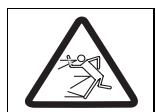
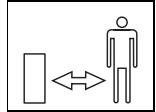
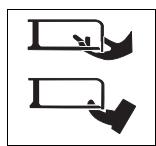
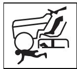
Keep third parties away from the danger area!
Risk of injury from rotating blades and other rotating parts.
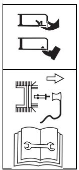
Always remove the spark plug connector before working on the cutters!
Keep fingers and feet well away from the cutters! Always switch off the appliance and remove the spark plug connector before adjusting, cleaning or checking it.
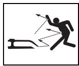
Risk of injury from propelled grass or solid objects that are propelled.
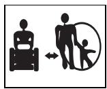
There must be no persons, especially children, or animals in the area of operation.

Working on steep slopes increases danger.
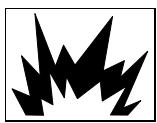
Caution! Risk of explosion.
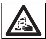
Battery acid/ Risk of injury.
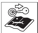
Withdraw the key from the ignition before all work on the unit and observe the instructions in this document.
Ensure that these symbols on the unit remain legible and are not obscured or covered.
Symbols in these
Operating Instructions
The following symbols are used in these instructions:

Danger
This informs you of the potential dangers associated with the described activity that represent a risk of injury.

Caution
This informs you of the potential dangers associated with the described activity that might result in damage to property.

Note
This indicates important information and application tips.
Positional information
Where a position on, or in relation to, the unit is described (e.g. left, right), this is always from the perspective of the driver, sitting on the driver seat and facing forward.

Note
The illustrations may differ in detail from the machine which you have purchased.
Operation and Display Elements

Caution
Damage to the lawn scarifier.
It is primarily the functions of the controls and display elements which are described here. Do not perform any functions yet!

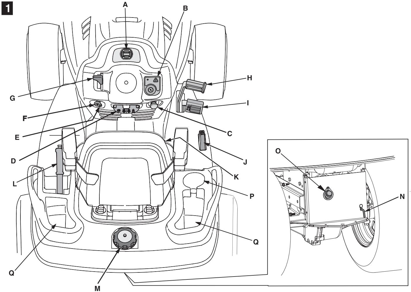
Display cluster (A)
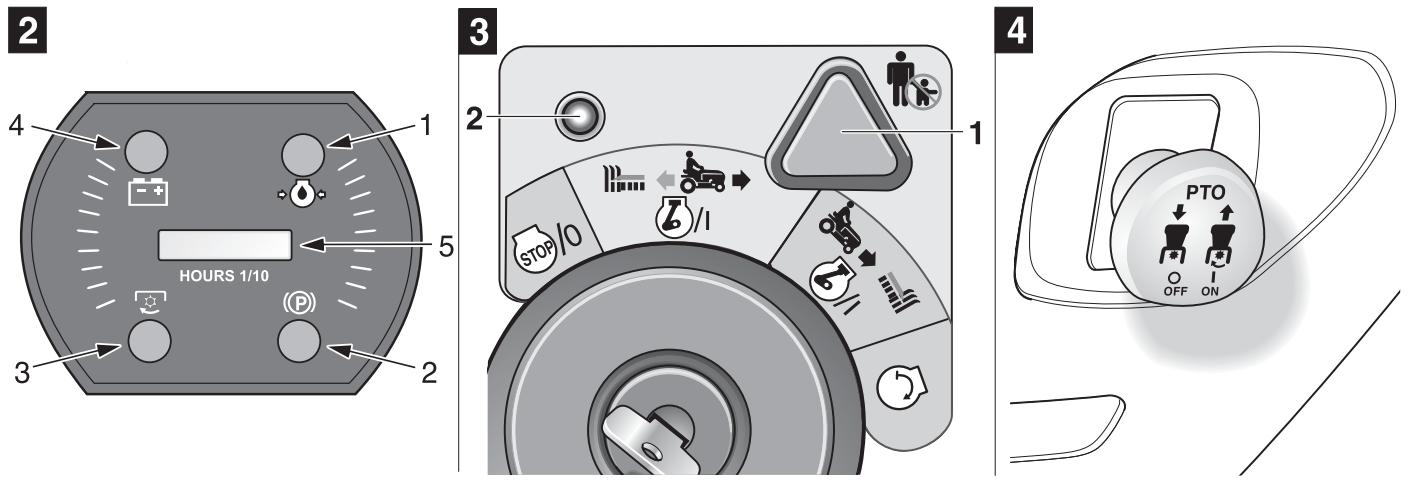
Figure 2
The display cluster can consist of the following elements, depending on the model.
Oil pressure (1):
When this indicator lamp lights up and the engine is running, immediately switch off the engine and check the oil level. If necessary, consult a garage.
Brake (2):
Indicator lamp lights up if the brake pedal is not depressed or the parking brake is not locked when the engine starts.
Cutter deck (PTO) (3):
The indicator lamp lights up when the cutters are not switched OFF at engine start (PTO).
Battery charge indicator (4):
When this indicator lamp lights up and the engine is running, the battery is low. If necessary, consult a garage.
Engine hour indicator/battery voltage (5):
Indicates the operating hours in hours and 1 / 10 hours on the display.
i Note
When the ignition is switched on, the battery voltage is displayed briefly and then the display switches to operating hours.
Operating hours are always counted except when the ignition key is on "Stop" or has been removed.
i Note
Every 50 operating hours (depending on model) oil change
"CHG/OIL" is indicated on the display for a period of 5 minutes.
This message is indicated for the next 2 operating hours. See engine handbook for oil change intervals.
Ignition lock with OCR function
Figure 3
This ignition lock features an OCR function (= user-controlled mowing in reverse gear).
Start:
Turn the key to the right until the engine is running, then release.
The key is set to (normal position) and permits mowing in forward gear.
OCR position:
Turn key to left of normal position to reverse mowing position 2 / 1/ and press the switch (1). The indicator light (2) comes on and indicates to the user that the unit can now mow in reverse and forward gear.
Stopping:
Turn the key to left to

i Note
Do not use the OCR function unless absolutely necessary, otherwise work with the key in the normal position. The OCR function switches off automatically as soon as the key is turned to the normal position or the engine is switched off (stop position or disconnection of the engine by the safety interlock system).
PTO-switch (C)
Figure 4
The PTO switch switches the cutter deck/accessories on and off via an electromechanical clutch.
ON = pull the switch.
OFF = press the switch.
Note:
When the safety lock system has automatically switched OFF the appliance (e.g. when reversing with activated cutters), first switch ON and then OFF the PTO switch to release the lock on the clutch.
Parking brake/
Speed control (D)
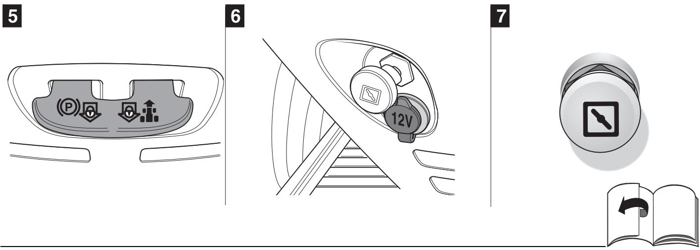
Figure 5
This switch has a dual function.
Actuate the parking brake (P):
Press down the brake pedal fully, and press the switch.
Releasing the parking brake:
Press down the brake pedal fully, the switch disengages.
Actuating cruise control
The forward speed selected when the switch was actuated (however not the maximum speed) is retained; you can take your foot off the accelerator pedal.
When the accelerator pedal or the brake pedal is depressed, the cruise control automatically switches off.
12 V socket (E) (optional)
Figure 6
Maximum current output 12 V/5 A
Choke (8)
Figure 7
To start a cold engine, pull out the choke.
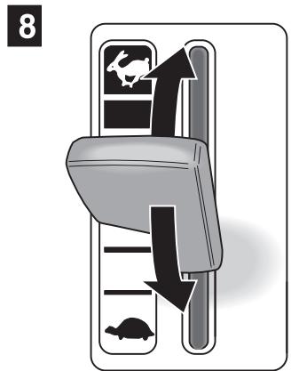
Throttle lever (G)
Figure 8
The engine speed can be adjusted continuously.
Fast engine speed =
Slow engine speed =
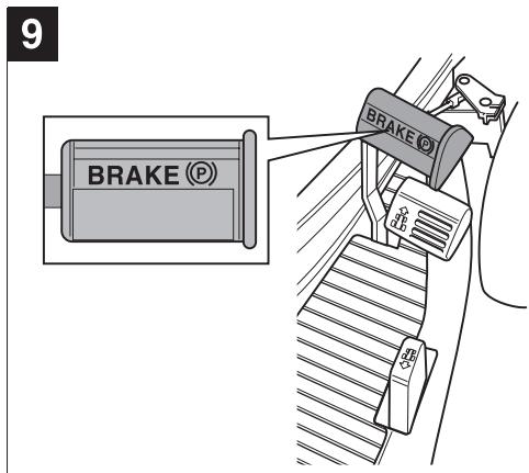
Brake pedal (H)
Figure 9
The brake pedal can be used to brake quickly, to engage and disengage the locking brake, and to switch OFF speed control.
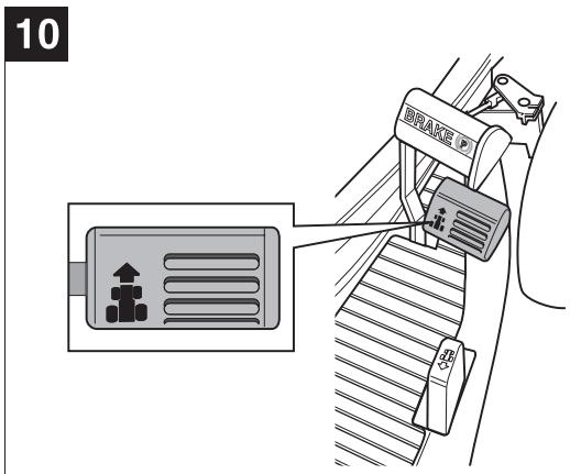
Forward pedal (I)
Figure 10
The pedal controls the speed in a forward direction.
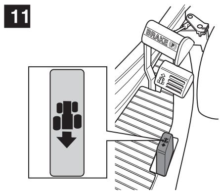
Reverse pedal (J)
Figure 11
The pedal controls the speed in a reverse direction.

Information on forward/ reverse pedal
To stop or change direction of travel, release the appropriate pedal.
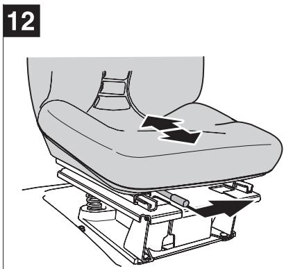
Adjusting lever for seat (K)
Figure 12
The driver's seat can be set with the seat adjustment lever.
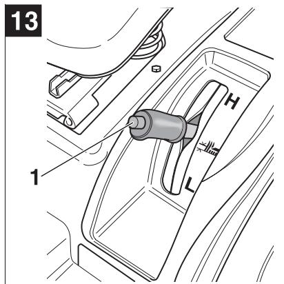
Cutting mechanism adjusting lever (L)
Figure 13
The cutting mechanism adjusting lever is used to raise and lower the cutting mechanism (accessory).
The height can be set to six different positions by pressing the button on the cutting mechanism adjusting lever and by positioning the cutting mechanism adjusting lever.
The force is transmitted mechanically and is regulated by a spring.
Filler inlet for fuel (M)
Figure 1
Gear release lever (N)
Figure 1
Before you can push the appliance with the engine switched OFF, you must first pull out and then push down this lever.
To drive the appliance again, push up and press in the lever.
The lever is situated on the rear panel of the machine.
Dipstick for gear oil (O)
Figure 1
Can holder (P)
Figure 1
Storage recess (Q)
Figure 1
Assembly
Opening the bonnet
Danger
The engine and the side covering remain hot for a time after the engine has been switched off. Working on hot parts can lead to severe burns. Before you start working in this area, allow all parts to cool first.
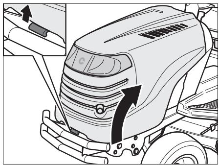
- Park the tractor on an even, solid surface.
Engage the parking brake.
Conduct all work with the engine switched off.
Pull up the locking plate.
Open the hood.
Commissioning the battery
Danger
Risk of poisoning and injury from battery acid
Wear protective goggles and gloves. Do not allow battery acid to come into contact with the skin.
Should battery acid splash into your face or eyes, wash immediately with cold water and consult a doctor.
Should you inadvertently swallow battery acid, drink plenty of water and consult a doctor immediately.
Store batteries in a safe place out of the reach children. Never tilt the battery; the battery acid may run out. Bring the remaining, unused battery acid to your dealer or to a waste disposal company.
Caution
Risk of fire, explosion and corrosion from the battery acid and emitted gases
Should battery acid spill or splash onto parts of the unit, clean it off immediately. Battery acid has corrosive effects.
Do not smoke. Keep burning and hot objects away from the battery and battery acid. Charge the battery in well-ventilated, dry enclosures only. A short-circuit may occur when working on the battery. Never lay tools or metal objects on the battery.
If a "maintenance-free/ sealed" battery (type 1) is supplied
(Battery without filler plugs)
The battery is filled with battery acid and sealed in production. However, even a "maintenance-free" battery requires maintenance if it is to have a longer service life.
- Keep the battery clean.
- Avoid tilting the battery or turning it over. Even a "sealed" battery will leak electrolyte if it is tilted or turned over.
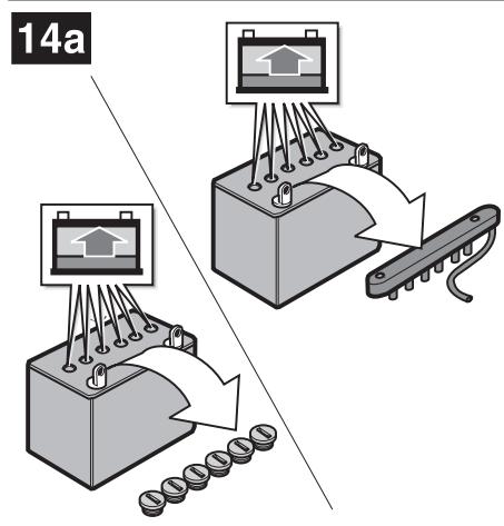
If an empty battery (type 2) is supplied
(Battery with filler plugs)
Figure 14
- Remove the filler plugs of the battery cells.
- Fill each cell slowly with battery acid up to 1 ~cm below the filling opening.
- Leave the battery to stand for 30 minutes so that the lead can soak up the battery acid.
- Check the level of the battery acid, add more if necessary.
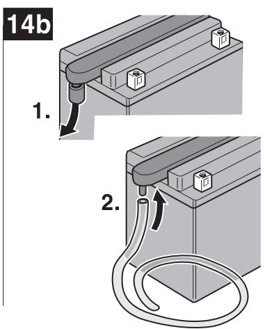
Before using the battery for the first time, charge it using a battery charger (max. charging current 12 Volt / 6 Ampere) for 2 to 6 hours. After charging the battery, first unplug the charger and then disconnect the battery (see also the operating instructions for the battery charger). - Re-insert the filler plugs of the battery cells.
Install the battery in the unit. - Remove the strip seal from the battery vent. Connect the venting hose so that the free end points downwards in the appliance. The hose must always allow free passage! (Figure 14b)
-
First connect the red cable (+), and then the black cable (-).
Thereafter, use only distilled water to top up the battery (check every 2 months). -
Keep the battery clean.
Caution
Note the order of terminals when connecting and disconnecting the battery.
Installation:
- First connect the red cable (+ / positive post), and then the black cable (- / negative post).
Removal: - First disconnect the black cable (-/ negative post), and then the red cable (+/ positive post).
Servicing the battery (type 1/2)
Before leaving the unit idle for a longer period, it is advisable to remove the battery and charge it. The battery should be charged every 2 months during the idle period (off season), and also before recommissioning the unit at start of season (consult a specialist workshop for further information).
Installing the steering wheel
Figure 15
- Place the collar (2, if provided with model) and the steering wheel (1) on the steering shaft.
- Place on top the washer (3) with the convex side up, and secure the steering wheel with the screw (4).
Insert the cover (5).
Operating safety
Also follow the instructions in the engine handbook!
Danger Risk of injury
No person, especially children, and/or animals should be allowed to stand close to the mower while it is in use. They could be injured by stones or similar objects that might be thrown out. Under no circumstances may the unit be operated by a minor.
Be particularly careful when mowing in reverse gear (units with OCR switch). Ensure that all persons are outside the working area of the unit.
Never empty the grass catcher while the engine is still running. While emptying the grass catcher, you yourself or some other person could be injured if the contents of the catcher are ejected at high speed.
When mowing on steep slopes, there is a risk of the mower tipping over and you could be injured as a result. Never drive across the face of a slope, always up and down the slope. The mower should not be driven on slopes with a maximum incline greater than 20% . Never turn on a slope.
When mowing wet grass, there is a greater risk of the unit sliding as a result of reduced wheel grip.
This can result in the unit crashing.
Excessive speed can increase the risk of an accident.
Maintain a safe distance at all times from particularly steep slopes, trees, bushes and hedges.
Be particularly cautious when driving in reverse.
Check the area in which you intend to use the unit and remove all objects that might be hit and propelled by the unit.
If the cutting tool hits a foreign object (e.g. stone) or if the machine starts vibrating violently: stop the engine immediately. Examine the unit for damages.Consult a specialist workshop if damage has occurred.
In the case of mowers with rotary blades, never stand in front of grass ejection holes.
Never place your hands, feet, or other parts of the body near rotating parts.
Switch OFF the engine, remove the ignition key, and disconnect the spark plug terminal before you clear the ejector of blockages and other hindrances.
Risk of suffocation from carbon monoxide
Run the internal combustion engine outdoors only.
Risk of explosion and fire
Petrol vapour is explosive and petrol itself is extremely flammable.
Fill up will petrol before you start the engine. Always keep the fuel tank sealed while the engine is running and while it is still hot.
Only refuel the unit when the engine is switched off and fully cooled.
Open fire or sparks must be avoided and you should not smoke while refuelling the unit. Refuel the unit in open spaces only.
If fuel has spilled, do not start the engine. Push the mower away from the area where the petrol was spilt and wait until the petrol fumes have evaporated.
To avoid fire hazard, keep the following parts free of grass and escaping oil: engine, exhaust, battery, fuel tank.

Danger
Injury hazard due to defective mower
The unit should only be operated when it is in perfect working order. Conduct a visual check before each use. Check in particular the safety features, cutting tools and mountings, operation elements, and threaded joints for damage and sureness.
Always replace damaged parts before operating the unit.

Operating times
Observe the national or bylaws for the times you may operate the appliance. You may have to consult your local authority.
Before each use

Note
The engine has already been filled with oil at the factory - please check the oil, if required refill.
Check:
all protective features
the engine-oil level (see the engine handbook)
the gear-oil level (see below)
the fuel level (see below)
the tyre pressure (see side of tyre)
- the side covering and the area around the air filter for dirt and grass
the cutting mechanism for dirt and grass
Check the fuel level:
- Open the tank and add fuel as required (refer to the engine handbook to determine the correct type of fuel).
Wipe away any spilt fuel.
Close the tank
Check the level of the gear oil:
- Withdraw the dipstick from the filler opening.
Wipe off the dipstick. - Check the oil level. The oil level should be between the two markings.
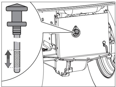
Clean the area around the filler opening.
If required, pour oil into the oil filling orifice (use "Special Drive System Oil" only - contact your dealer).
- Re-insert the dipstick and check that it is secure.
Preparing for operation
- Park the tractor on an even, solid surface.
Engage the parking brake.
Conduct all work with the engine switched off. - Withdraw the key from the ignition.
Before all work on moving parts, open the bonnet and disconnect the lead to the spark plug.
Adjusting the driver seat
Figure 12
Take your place on the driver seat.
- Adjust the seat to the desired position.
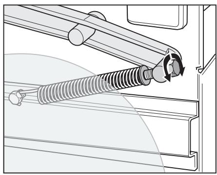
Setting the spring tension on the cutting mechanism adjusting lever

Note
The restraining force of the spring for the cutting mechanism adjusting lever can be adjusted to suit the operator. The tractor can be operated with a variety of accessories (e.g. for ploughing snow). As the accessories vary in weight, it may be necessary to adjust the spring force required for raising the respective accessory.
Turn the adjusting screw clockwise to increase the spring force.
Turn the adjusting screw anticlockwise to decrease the spring force.
Setting the supporting wheels (depending on model)

Note
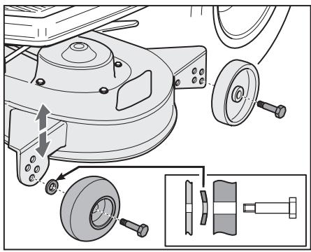
The supporting wheels prevent the cutting mechanism for getting stuck in tufts of grass as you are mowing. Set the supporting wheels to the operating position after you have set the cutting mechanism to the correct cutting height. All supporting wheels must be set to the same position.

Caution
The more uneven the terrain that you are mowing, the deeper you should set the supporting wheels in order to prevent the cutting mechanism coming into contact with the ground.
- Set the cutting mechanism adjusting lever to the highest position.
- Release the locks of the supporting wheels.
- Set the supporting wheels so that they just touch the ground.
Lock the supporting wheels.
Type A

Type B
Setting the blade-to-ground distance

Note
Set the height of the blades from the ground so that an even cut is achieved.
Preparation:
- Set the supporting wheels so that they do not touch the ground.
- Set the cutting mechanism adjusting lever to the highest position.
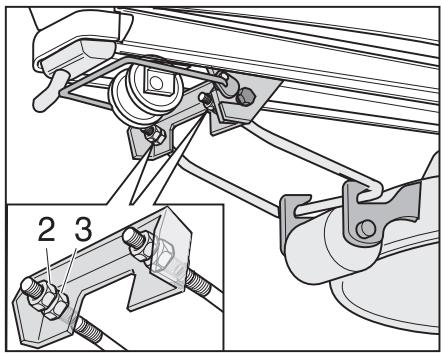
Aligning the blades parallel to the ground
- Rotate the blades (1) 90^ to the direction of travel.
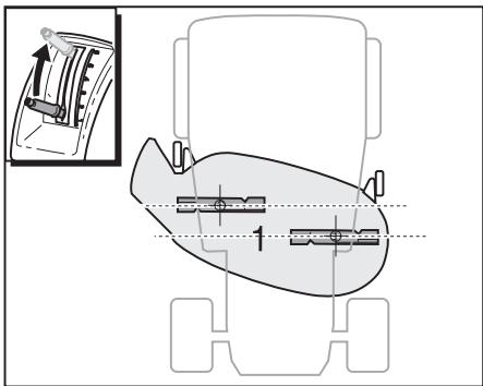
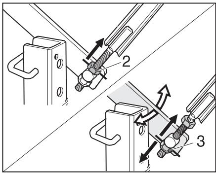
Loosen the lock nut (2).
- Bring the cutting mechanism to its correct height by adjusting the adjusting nut (3):
Turn the adjusting nut clockwise = the cutting mechanism rises.
Turn the adjusting nut anticlockwise = the cutting mechanism sinks.

Note
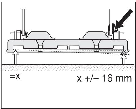
The blades must be at an equal distance from the ground.
- Check this distance for each blade.
- Tighten the lock nut (2).
Setting the inclination of the blades
- Rotate the blades (1) parallel to the direction of travel.
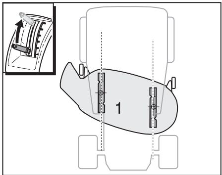
- Loosen the lock nuts (2) on the front lifter rod.
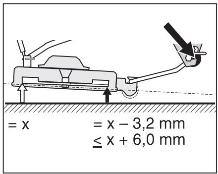
- Vary the inclination of the blades with the adjusting nuts (3)
- Check that the new setting is correct.
- Tighten the lock nuts (2).
Setting the cutting height
Figure 13

Note
You can keep your lawn healthy by mowing off no more than 1 / 3 of the stem length at a time. The cutting height should be increased above the normal level when mowing uneven surfaces.
Press the button (1).
Draw up or lower the cutting mechanism adjusting lever.
- Release the button so that the cutting mechanism adjusting lever locks into place.
Starting the engine
Take your place on the driver seat.
- Depress the brake pedal fully or engage the parking brake.
- Switch off the engage switch (PTO).
raise the cutters to the top,
Set the throttle lever (Figure 8) to
If the engine is cold, pull out the choke (Figure 7).
Turn the ignition key (Figure 3) to until the engine is running (attempt to start the engine for max. 5 seconds, wait 10 seconds before attempting to start the engine again). When the engine is running, set the ignition key to /I
- Slowly push back the choke (Figure 7).
- Return the accelerator lever (Figure 8) until the engine runs smoothly.
Stopping the engine
- Move the throttle (Figure 8) to the middle position.
Let the engine run for approx. 20 seconds.
Turn the ignition key (Figure 3) to l /0. - Withdraw the key from the ignition.
- Engage the locking brake before leaving the appliance.
Driving the tractor
Danger
Abrupt takeoff, stopping suddenly, and driving at excessive speeds raise the risk of accidents and can cause damage to the unit. Never set/adjust the driver's seat while the unit is moving.
i Note
Be particularly careful when reversing. Never change direction without first stopping the appliance. You can set the direction of travel and the travelling speed using the forward and reverse pedals.

formation on mowing
- In normal mowing mode (see Operation, ignition lock):
Before reversing the machine, switch off and raise the cutter deck.
-In reverse mowing mode 6/1/ (see Operation, ignition lock):
Exercise extreme caution when reverse mowing and do not activate unless absolutely necessary.
Start the engine (see previous section).
Engaging the cutting mechanism or other driven accessories
Set the throttle lever into position.
- Switch on the engage switch (PTO) (observe the following instructions on using the engage switch).
Lower the cutter deck.
- Depress the brake pedal fully, the parking brake releases.
- Press the forward pedal slowly forward.
Keeping the travelling speed constant
- Press the forward pedal slowly forward until the desired travelling speed is reached.
- Press the speed pilot switch. The speed pilot switch holds the forward pedal in this position.
Take your foot from the forward pedal, the tractor travels at constant speed.
Cruise control is automatically deactivated by depressing the accelerator pedal or the brake pedal.
Stopping/Parking the tractor
Release the accelerator.
- Press the brake pedal, wait until the tractor stops and engage the parking brake.
- Switch off the engage switch (PTO).
- Turn the ignition key to the 0 (STOP) STOP position.
Lower the cutting mechanism or any other accessory equipment.
- Withdraw the key from the ignition.
i Instructions on using the engage switch (PTO) on new, unused tractors
Before you switch on the engage switch (PTO) under load (mowing etc.), first do the following:
■ Engage the parking brake.
- Start the engine and allow it to warm up for a few minutes.
- Set the engine rpm to between 50 % and 75 % using the throttle lever.
- Switch the engage switch on and off approx. 8 times in intervals of 10 seconds (switch on for 10 sec., then switch off for 10 sec.).
- Switch off the engage switch and the engine.
i Instructions for using the engage switch (PTO) under load
- Set the engine rpm to between 50 % and 75 % using the throttle lever.
- Switch on the engage switch.
- Set the engine rpm to maximum using the throttle lever.
When the tractor is being operated with the engage switch on, the safety lock feature will
- switch off the engine automatically if the driver leaves the driver seat,
- the clutch switch is automatically deactivated for reversing (provided the OCR switch has not been activated).
To turn on the engage switch (PTO) again, you must first switch it off and then switch it on again.
To attain optimum mowing results
The best way to mow

Note
You can keep your lawn healthy by mowing off no more than 1 / 3 of the stem length at a time. The cutting height should be increased above the normal level when mowing uneven surfaces.
- Set the cutting mechanism to the cutting height.
- Set the supporting wheels according to the cutting height.

Note
Cut the first two rounds so the cut grass is thrown out sideways into the middle.
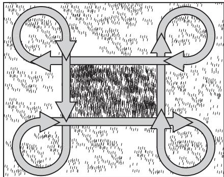
- Never allow the grass to grow too long.
- Never cut the grass too low.
- Drive in a straight line.
i Note
If the engine should cut out while mowing on a slope, secure the tractor against rolling by engaging the parking brake.
Mulching with accessory (optional)
The grass is chopped up fine (approx. 1 cm) during mowing and is left on the lawn. The lawn therefore retains a lot of nutrients. Please note the following:
Do not mow wet grass.
- Never mow more than max. 2 cm of the total grass length.
Drive slowly.
Have the engine at max. rpm.
Clean the mower cover regularly.
Installing and removing the cutter deck
Before all work on the unit:
- Park the tractor on an even, solid surface.
Engage the parking brake.
Conduct all work with the engine switched off. - Open the bonnet and disconnect the cable to the spark plug.
Attaching the grass flap
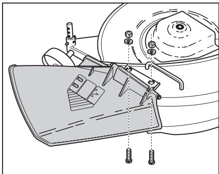
Mounting mulching accessory (optional)
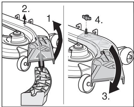
Version A
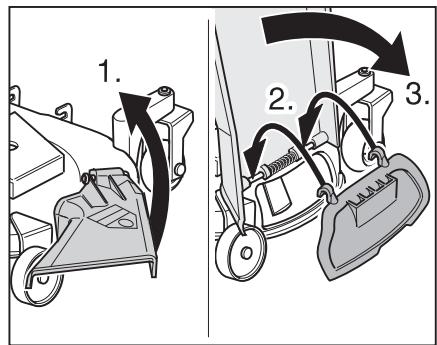
Version B
Mounting the cutting mechanism
Preparing for assembly
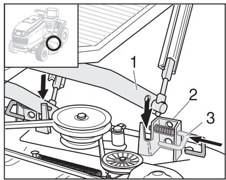
- Place the cutting mechanism (1) at the left side of the tractor.
- Set the cutting mechanism adjusting lever to the highest position.
Align the cutting mechanism with the tractor. -
Draw both latch pins (2) out of the receivers on the cutting mechanism and turn them outwards.
-
Have the lifter rod ready (3) (depending on tractor design, this will already be pre-mounted on the tractor and secured with cable straps. Cut the cable straps).
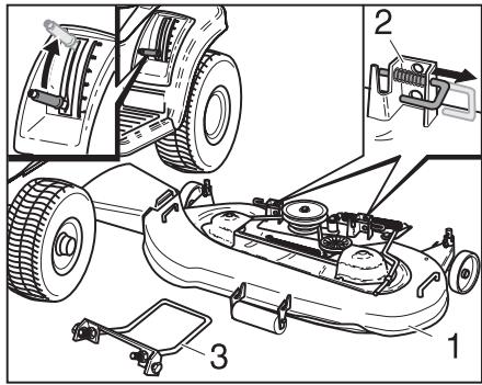
- Bring the supporting wheels (4) into the assembly position (varying in design).
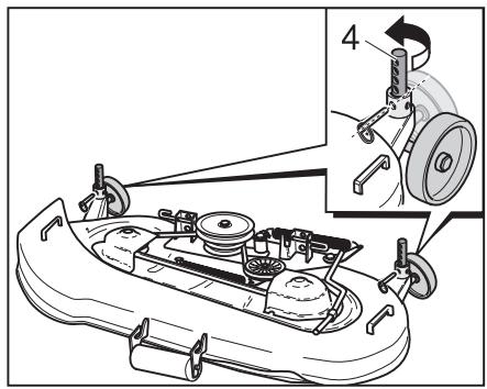
- Slide the cutting mechanism under the tractor.
Press down, and hold down the quick-mounting bar (5) on the tractor. - Hang the lifter rod into the two receiving slots (6) on the tractor.
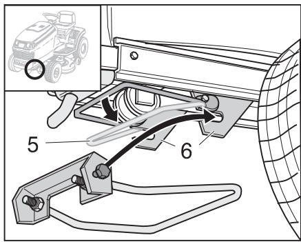
Release the quick-mounting bar (5).
- Set the cutting mechanism adjusting lever to the lowest position.
- Push up the lifter rod (3) and hold it up.
Align the receiving slots of the cutting mechanism with the lifter rod.
Lower the lifter rod (3) and place it in the receiving slots.
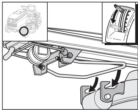
Bring the accessory receiver (1) slowly into both receiving slots (2) on the cutting mechanism.
Position both latch pins (3) in the receivers and allow them to lock into place.
Mounting the V-belt
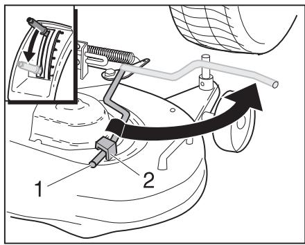
- Set the cutting mechanism adjusting lever to the lowest position.
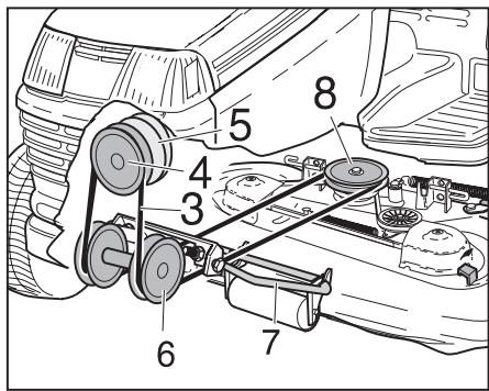
- Remove the belt tensioning lever (1) from its catch (2) and move it out.
Danger
Hot exhaust pipe. You run the risk of sustaining severe burns if you mount the V-belt while the engine is still hot. Wait until the engine and the exhaust pipe have cooled before mounting the V-belt.
Bring the V-belt (3) up underneath the tractor frame.
- Place the V-belt in the pulley (4) on the engine drive (5).
Turn the pulley of the engine drive.
Bring the V-belt into position in the two pulleys (6).
Bring the V-belt out through the front lifter rod (7).
- Mount the V-belt on the middle pulley (8) on the cutting mechanism.
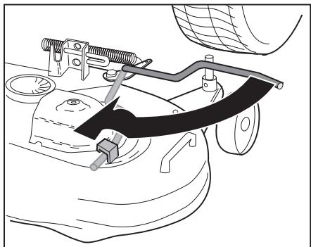
- Move the belt tensioning lever inwards and lock it into its catch.
- Put the supporting wheels back into the operating position (design varies).
Demounting the cutting mechanism
- Set the cutting mechanism adjusting lever to the lowest position.
Demounting the V-belt
- Remove the belt tensioning lever (1) from its catch (2) and move it out.
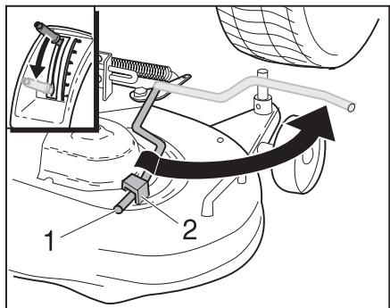
Danger
Hot exhaust pipe. You run the risk of sustaining severe burns if you demount the V-belt while the engine is still hot. Wait until the engine and the exhaust pipe have cooled before demounting the V-belt.
- Remove the V-belt from the middle pulley (8) on the cutting mechanism.
- Remove the V-belt from the pulley (4) on the engine and draw it out of the tractor frame.
Push in the belt tensioning lever and place it into its catch (2).
Demounting the cutting mechanism
Press down, and hold down the quick-mounting bar (1).
- Remove the lifter rod (2) from both slots (3) on the tractor.
- Release the quick-mounting bar.
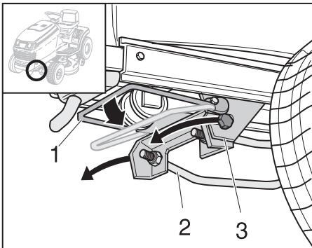
Take the lifter rod out of both receiving slots on the cutting mechanism.
Remove the lifter rod.
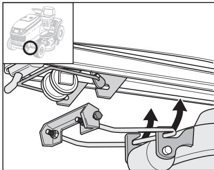
- Draw both latch pins (1) out of the receivers (2) on the cutting mechanism and turn them outwards.
- Set the cutting mechanism adjusting lever to the highest position.
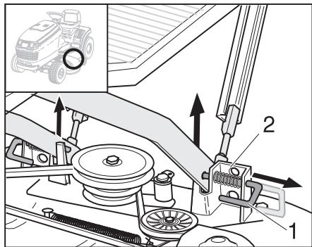
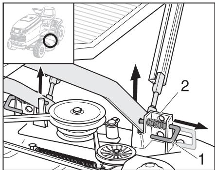
Put the supporting wheels into the drag position (design varies).
- Remove the accessory receiver from both receiving slots on the cutting mechanism.
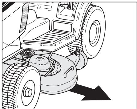
Draw the cutting mechanism to the left from under the tractor.
Replacing the V-belt
Check the V-belts regularly. Replace the V-belt as soon as it shows signs of wear.
i Note
The V-belt for the cutting mechanism may only be changed when the cutting mechanism is demounted.
Transporting the appliance
If changing location, drive the lawn tractor short distances only. otherwise transport it by vehicle.
Note: The mower is not approved for public thoroughfares in accordance with StVO.
Short distances
Danger
Solid objects may be hit/propelled by the rotating cutting mechanism causing damage.
Always switch off the cutting mechanism before moving the mower.
Long distances
Caution
Transport damages
The mode of transport used (e.g. transport vehicle, loading ramp) must be used in accordance with guidelines (refer to the respective operating instructions). When transporting, secure the mower against slipping.
Spilt fuel pollutes the environment
The appliance must not be tilted when it is transported.
- Have the transporting vehicle ready.
- Lay the loading ramp to the transporting vehicle.
- With the unit in free-wheel, push it up onto the transporting vehicle (disengage the transmission in the case of units with hydrostatic drive).
■ Engage the parking brake. - Secure the machine to prevent it from moving.
Cleaning / Servicing

Danger
Injury hazard if engine is started inadvertently
Protect yourself against injury.
Before all work on this unit
- Switch off the engine.
- Take out the ignition key.
- Actuate the parking brake.
- wait until all moving parts have come to rest and the engine has fully cooled,
- remove the spark plug connector on the engine in order to prevent the engine from accidentally being started.
Cleaning
Clean the machine

Caution
Do not use high-pressure media for cleaning.
If the unit is not cleaned, material damage and function impairments will occur.
If possible, clean the unit directly after work.
- Park the unit on a solid, even surface.
■ Engage the parking brake.
Cleaning the cutting mechanism
Danger
Injury hazard due to sharp cutting blade
Wear protective gloves.
If the unit has more than one cutting mechanism, moving one cutting mechanism may cause the other cutting mechanisms to move as well. Take special care when cleaning cutting mechanisms.
Caution Damage to engine
The mower must not be tilted to an angle greater than 30^ . Fuel may run into the combustion chamber causing engine damage.
- Raise the cutting mechanism fully.
- Clean the cutting area using a scrubbing brush, a hand brush or a cloth.
Cutters with cleaning nozzle (optional)
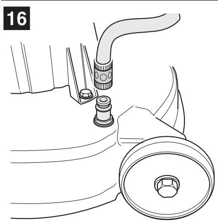
Figure 16
Place the appliance on an even surface free of debris, stones, etc., and engage the locking brake.
- Use a commercially available quick-release coupling to attach a water hose.
2.Start the engine.
-
Lower the cutters, and switch ON for a few minutes.
-
Switch OFF the cutters and engine.
-
Detach the water hose.
Repeat steps 1 to 5 for the second cleaning nozzle (if provided).
At the end of cleaning (steps 1 to 5):
raise the cutters to the top,
- start the engine, and switch ON the cutters for a few minutes to dry them.
Cleaning the area of the air filter and the radiator grill
Risk of burns
Before you start working in this area, allow all parts to cool first.
Opening the bonnet.
Remove grass and chaff.
Close the bonnet.
Servicing
Observe the servicing instructions in the engine manual.
At the end of the grass-cutting season, have the lawn scarifier checked and serviced in a specialist workshop.
Caution
Environmental hazard caused by engine oil
After every oil change, bring the old oil to an appropriate collection point or a waste disposal company.
Environmental hazard caused by batteries
Used batteries do not belong in domestic waste. Bring used batteries instead to your dealer or to a waste disposal company. Remove the battery before scrapping the unit.
Conduct maintenance and service work regularly.
Observe these.
Have your unit inspected by a specialist workshop at least once annually.
- Use original replacement parts only.
Use only permitted fuels and cleaning agents.
- Store lubrication oil and grease in clean containers and protect them against dirt and dust.
Heed all instructions on checking, testing, and preventative maintenance work as warranty claims will not otherwise be honoured.
- Park the tractor on an even, solid surface.
Engage the parking brake.
Conduct all work with the engine switched off. The engine must be allowed to cool.
- Open the bonnet and disconnect the cable to the spark plug.
Performing maintenance work
Operator
Work that is identified as capable of being done by the "Operator" may be done by any person who is capable of operating and maintaining the unit.
Service
Work identified with the term "Service" may only be carried out by a specialist workshop.

Note
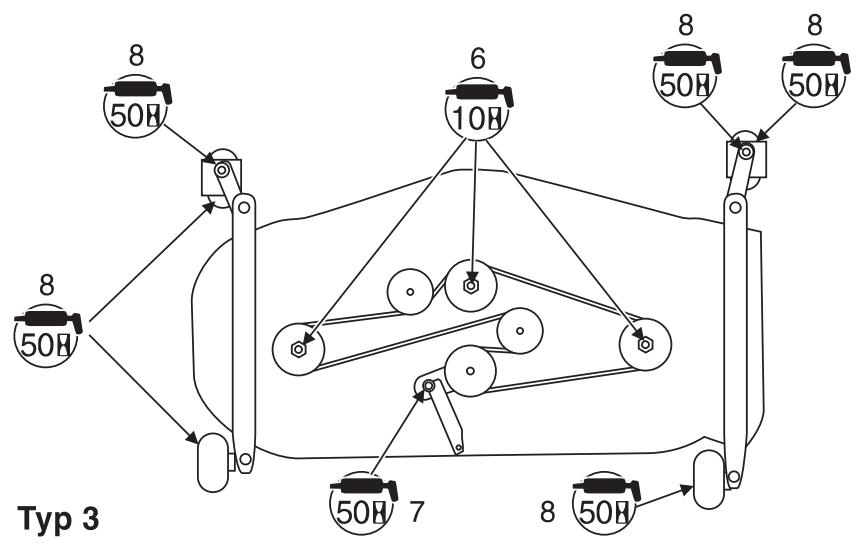
Use conventional grease guns and oil cans to lubricate the unit.
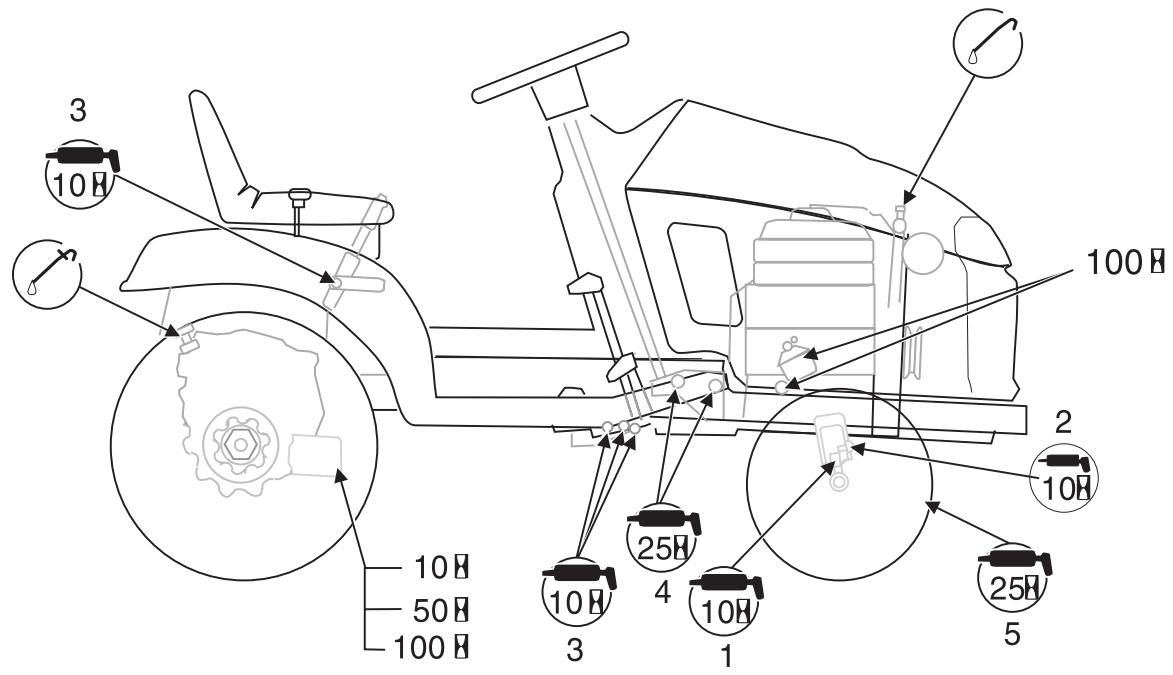
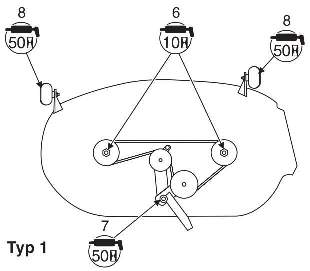
For lubrication chart drawing see fold-out pages at the front (Figure 18).

"Once off" maintenance work
In the case of a hydrostatic drive, have the gear-oil filter changed by a specialist workshop after the first 10, and again after the first 50 hours of operation. Consult a specialist workshop.
- Check the engine oil and the oil filter more frequently in the first few hours of operation. Refer to the handbook for the engine or consult a specialist workshop.
After the first 10 hours in operation, check the nuts on the rear wheels for tightness and tighten if necessary.
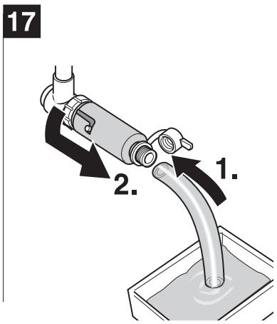
- Change the engine oil after the first 5 hours in operation. Use the oil channel or (optional) quick oil drain (Figure 17).
- Please follow the instructions in the engine handbook.
For further information see the maintenance table below.
Maintenance work and regularity
| When | Activity | Execution | To be done by |
| As necessary | Check the paper insert in the air filter | Check more frequently in the event of excessive dirt. Clean the paper insert of the air filter and replace when necessary (see handbook for engine). | Operator/Service |
| Change the engine oil and oil filter | Check more frequently in the event of excessive dirt. Change the engine oil and the oil filter as required (see handbook for the engine or consult a specialist workshop). | Operator/Service | |
| After every 10 hours or once monthly | Check the level of electrolyte in the battery (only necessary for type 2 batteries) | DangerDANGERBattery acid and battery acid fumes can injure your skin and eyes. Take due care when adding distilled water and always wear goggles and protective gloves. | Operator/Service |
| Remove all grass and chaff from the area of the air filter, the radiator grill and the side covering | Remove the side covering and remove grass and chaff (see "Cleaning"). | Operator | |
| After every 10 hours or once monthly | Check the air filter | Clean or replace as required (see handbook for engine). | Operator/Service |
| Lubricate the bolt (1) on the front axle on both sides (see fold-out page) | Use 251 EP grease or similar multi-purpose lithium grease, no. 2. | Operator | |
| Lubricate the steering stub axle (2) on both sides (see fold-out page) | Use 251 EP grease or similar multi-purpose lithium grease, no. 2. | Operator | |
| Lubricate the pivot points of the foot and lever controls (3) (see fold-out page) | Use only high-quality lubrication oil to do this. Apply the oil liberally to the pivot points. | Operator | |
| Lubricate the shafts (6) of the mower unit (see fold-out page) | Use 251 EP grease or similar multi-purpose lithium grease, no. 2. | Operator | |
| Lubricate belt-tensioning lever (7) of the cutting mechanism (see fold-out page) | Use 251 EP grease or similar multi-purpose lithium grease, no. 2. | Operator | |
| After every 25 hours or three times per season | Lubricate both bearings of the steering housing (4) (see fold-out page) | Use 251 EP grease or similar multi-purpose lithium grease, no. 2. | Operator |
| Lubricate both bearings (5) of the front wheels (see fold-out page) | Use 251 EP grease or similar multi-purpose lithium grease, no. 2. | Operator | |
| After every 50 hours or twice per season | Lubricate the supporting wheels (8) of the cutting mechanism (see fold-out page) | Use 251 EP grease or similar multi-purpose lithium grease, no. 2. | Operator |
| After every 100 hours or once annually | Change the gear-oil filter (only for hydrostatic drive | Change the gear-oil filter. | Service |
| Check the paper insert in the air filter | Replace when necessary (see handbook for engine). | Operator/Service | |
| Change the engine oil and oil filter | Refer to the handbook for the engine or consult a specialist workshop. | Operator/Service |
Shutting down the machine

Caution
Damage to mower materials
Store the unit with the engine cooled in a clean, dry enclosure only. Always protect the mower against rust if it is to be left for comparatively long periods, e.g. over the winter. At the end of the season or if the appliance will not be used for longer than a month:
Clean the mower and the grass catcher.
Wipe down all metal parts with an oily cloth or apply oil spray to protect against rust.
- Charge the battery with a battery charger.
Before winterising the appliance, remove the battery. The battery must then be charged and kept in a dry, cool place (protected against frost), and recharged every 4 to 6 weeks and before the next use.
Drain out the fuel (in an open space) and prepare the engine for storage as described in the handbook for the engine.
Inflate the tyres in accordance with the specifications on their walls.
- Store the unit in a clean, dry enclosure.
Warranty
In each country, the warranty conditions issued by our company and/or importer apply.
Defects in the equipment will be rectified by us free of charge during the warranty period where these are the results of flaws in the material or in the manufacture of the equipment. In case of warranty claims, please contact your dealer or nearest branch office.
Engine
The manufacturer of the engine is liable for all engine-related problems with respect to output power, power measurement, specifications, warranty, and service. Informations can be found in the owner / operator handbook provided separately by the engine manufacturer.
Troubleshooting

Danger
Injury hazard if engine is started inadvertently
Protect yourself against injury. Before all work on this unit
- Switch off the engine.
- Take out the ignition key.
- Engage the locking brake.
- Wait until all moving parts have come to rest and the engine has fully cooled.
- Pull off the cap of the spark plug so that the engine cannot inadvertently start.
Problems that occur while you are using the mower are often caused by something simple which you will probably be able to rectify yourself. In cases of doubt your specialised garage will be pleased to assist you further.
Eliminating faults
Operator
Work that is identified as capable of being done by the "Operator" may be done by any person who is capable of operating and maintaining the unit.
Service
Work identified with the term "Service" may only be carried out by a specialist workshop.
| Fault | Possible cause | Action | To be done by |
| Difficulty starting the engine | Tank empty | Fill the fuel tank(see handbook for engine). | Operator |
| Fuel line or carburettor blocked | Clean the fuel line and the carburettor(see handbook for engine). | Service | |
| Fuel filter blocked | Clean or replace the fuel filter(see handbook for engine). | Service/Operator | |
| Choke and throttle at wrong position | Actuate the choke.Move throttle to . | Operator | |
| Spark plug dirty | Clean or replace the spark plug(see handbook for engine). | Service/Operator | |
| Battery does not give current | Check battery, recharge or replace. | Service | |
| Safety interlock system has actuated | To start the engine, first sit down on the driver's seat. Press down fully the brake pedal or engage the locking brake. Switch off the engage switch (PTO). | Operator | |
| The engine does not run smoothly or splutters | Engine not in tune | Have the engine tuned. | Service |
| The ignition spark does not occur | Check the spark plug and the wiring(see handbook for engine). | Service | |
| Carburettor incorrectly set | Reset the carburettor(see handbook for engine). | Service | |
| Air filter is very dirty | Clean or replace the air filter(see handbook for engine). | Service | |
| Supply of air to the engine is insufficient | Remove grass and chaff from the radiator grill and the side covering(see “Cleaning”). | Operator | |
| Brake does not grip | The brake setting is no longer correct or the brake pads are worn out | Switch off the engine and have the brake settings checked. | Service |
| Strong vibration | Damaged blade shaft or defective blades | Switch OFF appliance immediately.Have defective parts replaced in a specialist workshop. | Service |
| Engine is running,cutter deck is not mowing | V-belt torn | Have the V-belt replaced in a repair shop. | Service |