
SCARABEO 250 I.E. - Scooter APRILIA - Notice d'utilisation et mode d'emploi gratuit
Retrouvez gratuitement la notice de l'appareil SCARABEO 250 I.E. APRILIA au format PDF.
| Type de produit | Scooter 250 cm³ |
| Marque | APRILIA |
| Modèle | SCARABEO 250 I.E. |
| Longueur maximale | 2263 mm |
| Largeur maximale | 790 mm |
| Hauteur maximale (au pare-brise) | 1419 mm |
| Hauteur de selle | 785 mm |
| Poids à vide | 194 kg |
| Charge maximale (conducteur + passager + bagages) | 190 kg |
| Type de moteur | Monocylindre, 4 temps, 4 soupapes, refroidissement par air forcé |
| Cylindrée | 244,29 cm³ |
| Alimentation | Injection électronique avec pompe à essence électrique |
| Capacité du réservoir (réserve incluse) | 13,2 L |
| Réserve de carburant | 3 L |
| Carburant recommandé | Essence sans plomb premium, indice d'octane min. 95 (NORM) ou 85 (NOMM) |
| Frein avant | Disque Ø 260 mm, commande hydraulique |
| Frein arrière combiné | Double disque : avant Ø 260 mm, arrière Ø 240 mm |
| Pneu avant | 110/70 - 16' 52P (tubeless) |
| Pneu arrière | 140/70 - 14' 68P (tubeless) |
| Pression des pneus (conducteur seul, avant et arrière) | 2,1 bar (avant) / 2,1 bar (arrière) |
| Batterie | 12V - 14 Ah |
| Fusibles | 30 A, 15 A, 10 A |
| Ampoules (feu de route/croisement) | 12V - 55W / 12V - 55W |
| Huile moteur (vidange incluant filtre) | 1100 cm³ (SAE 5W40, API SL, ACEA A3, JASO MA) |
| Huile de transmission | ~250 cm³ (SAE 75W90, API GL4 GL5) |
FOIRE AUX QUESTIONS - SCARABEO 250 I.E. APRILIA
Questions des utilisateurs sur SCARABEO 250 I.E. APRILIA
0 question sur cet appareil. Repondez a celles que vous connaissez ou posez la votre.
Poser une nouvelle question sur cet appareil
Téléchargez la notice de votre Scooter au format PDF gratuitement ! Retrouvez votre notice SCARABEO 250 I.E. - APRILIA et reprennez votre appareil électronique en main. Sur cette page sont publiés tous les documents nécessaires à l'utilisation de votre appareil SCARABEO 250 I.E. de la marque APRILIA.
MODE D'EMPLOI SCARABEO 250 I.E. APRILIA
aprilia
APRIILAWLDLIKETOTHANKYOU
for choosing one of its products. We have compiled this booklet to provide a comprehensive overview of your vehicle's quality features. Please, read it carefully before riding the vehicle for the first time. It contains information, tips and precautions for using your vehicle. It also describes features, details and devices to assure you that you have made the right choice. We believe that if you follow our suggestions, you will soon get to know your new vehicle well and that it will continue to give you satisfactory service for many years to come. This booklet is an integral part of the vehicle and must be handed over to the homeowner in the event of sale.
SCARABEO 250 i.e.
aprilia
aprilia
The instructions in this booklet have been compiled primarily to offer a simple and clear guide to using the vehicle; it also describes routine maintenance procedures and regular checks that should be carried out on the vehicle at an Aprilia Dealer or Authorised Workshop. This booklet also contains instructions for simple repairs. Any operations not specifically described in this booklet require the use of special tools and/or particular technical knowledge; for these operations, please take your vehicle to an Aprilia Dealer or Authorised Workshop


Personal safety
Failure to completely observe these instructions will result in serious risk of personal injury.
Safeguarding the environment
Sections marked with this symbol indicate the correct use of the vehicle to prevent damaging the environment.
Vehicle intactness
The incomplete or non-observance of these regulations leads to the risk of serious damage to the vehicle and sometimes even the invalidity of the guarantee.
The symbols shown above are very important. They are used to highlight those parts of the booklet that should be read with particular care. As you can see, each sign consists of a different graphic symbol, making it quick and easy to locate the various topics. Before starting the engine, read this booklet thoroughly and the "SAFE RIDING" section in particular. Your safety as well as other's does not only depend on the quickness of your reflexes and agility, but also on how well you know your vehicle, the state of maintenance of the vehicle itself and your knowledge of the rules for SAFE RIDING. For your safety, get to know your vehicle well so as to safely ride and master it in road traffic IMPORANT This booklet is an integral part of the vehicle, and must be handed to the newowner in the event of sale.
INDEX
7
10
11
12
19
20
/ 21
22
23
24
24
25
25
26
26
26
27
28
28
29
30
31
32
34
37
40
42
44
51
51
54
55
VEHcE 7
Arrangement of the main components. 10
Dashboard 11
Analogue instrument panel. 12
DigitalLCDdisplay. 19
Setting the total and trip odometers. 20
Ock/date display. 21
Key switch 22
Locking the steering wheel. 23
Switch direction indicators. 24
Horn button 24
Light switch 25
Emergency flashing light button 25
Start-up button 26
Engine stop button 26
Fuel tank 27
Power supply socket. 28
The saddle 28
Identification 29
Rear top box opening 30
USE 31
Checks. 32
Refuelling 34
Tyre pressure. 37
Shock absorber adjustment. 40
Running in 42
Starting up the engine 44
Difficult start up. 51
Stopping the engine. 51
Catalytic silencer. 54
St and 55
56
58
65
66
67
69
70
73
77
80
83
83
84
89
92
97
98
99
102
104
106
107
110
111
111
112
113
114
117
119
122
125
130
133
135
136
145
Suggestions to prevent theft. 56
Safedriving. 58
MINENANCE 65
Engine oil level. 66
Engine oil level check 67
Engine oil top-up 69
Engine oil change. 70
Hub oil level. 73
Tyres. 77
Spark plug disnantlenent 80
Renowing the air filter. 83
Air filter cleaning 83
Cooling fluid level. 84
Checking the brake oil level. 89
Battery. 92
Use of a new battery. 97
Long periods of inactivity. 98
Fuses. 99
Lamps. 102
Front light group. 104
Headlight adjustment. 106
Front direction indicators. 107
Rear optical unit. 110
Rear turn indicators. 111
Number plate light. 111
Helnet compartnent lighting bulb. 112
Rear-view mirrors. 113
Front and rear disc brake. 114
Periodsof inactivity. 117
cleaning the vehicle. 119
Transport. 122
TECHNICAL DATA 125
Kit equipment. 130
SPARE PARTS AND ACCESSORIES. 133
PROGRAMMED MINIENANCE 135
Scheduled maintenance table. 136
SPECIAL FITINGS. 145
SCARABEO 250 i.e.

01
Chap 01
Vehicle
(01_02)
- 2
3
4
5
6 - 8
9
10 - 12
13
14
15
16 - 18
19
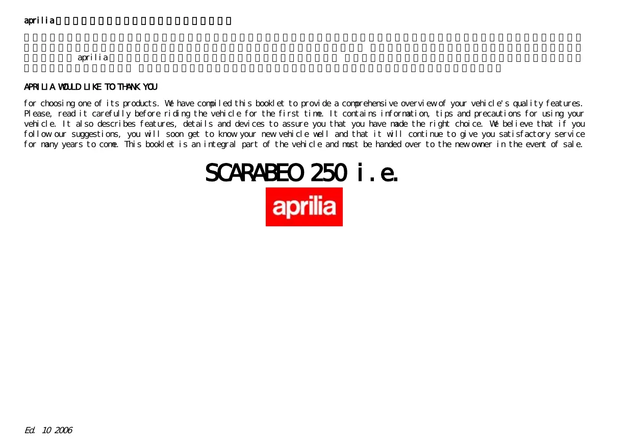
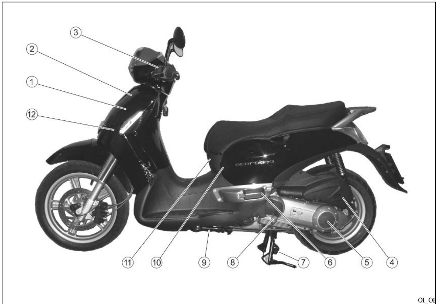
Arrangement of the main components (01_02)
KEY
- Expansion tank
2 Coolant expansion tank cap
3 Rear brake fluid reservoir
4 Air filter
5 Transmission cover
6 Left passenger footrest - Centre stand
- Engine oil level/refill cap
9 Side stand
10 Spark plug - Central inspection cover
12 Hbrn
13 Passenger handgrip - Front brake liquid tank
- Saddle opening switch
16 Fuel tank cap - Fuel tank
18 Battery
19 Secondary fusebox
20 Min fuseboxes - Left passenger footrest
20
21.
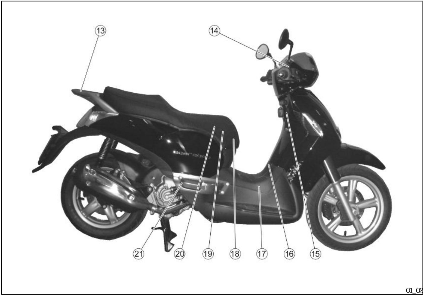
(01_03) Dashboard (01_03)
KEY
- Electrical controls on the left-hand side of the handlebars
2 2 Combined brake lever (front and rear)
3 Left rear-view mirror
4 4 Instruments and gauges
5 5 Front brake lever
6 Right rear-view mirror - 7.Throttle grip
8 Electrical controls on the right-hand side of the handlebars
9 Ignition switch / steering lock ON - OFF - LOCK (ON OFF - LOCK - OPEN GLOVE BOX - OPEN GLOVE BOX)
01_03
(01_04)
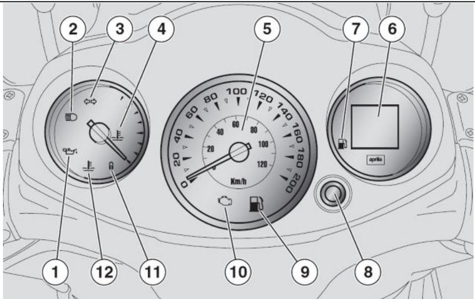
Analogue instrument panel (01_04)
KEY
-
2
3 -
Red engine oil pressure warning light
2 Blue high-beam warning light
3 Green turn indicator warning light
4 Coolant temperature gauge
5 Speedometer
6 Multifunction LCD panel
7. Fuel gauge
8 MDE 8 MDE button
9 Yellow anber low fuel warning light
10 EFI warning light
11. Antitheft warning light (IMD BLIZER)
12 Red high coolant temperature warning light
01_04
INSTRUMENT AND GAUGE DESCRIPTION
CAUINON
WHTHE KEY SET TO «ON» ALL THE PRE
INSTALLED WARNING LIGHTS, INSTRUMENT
PANEL LIGHTING AND ALL THE SEGMENT
INDISPLY3TURONFOR THE FIRST 3
SECONDS FOR AN INITIAL INSTRUMENT
CHECK
<ON
3
3
| <3> | Turn indicator warning light "3" |
| Flashes when the turning indication is activated | |
| <2> | High-beam warning light "2" |
| Turns on when the front headlamp high-beampuls is activated or when the high-beam light is flashed (PASSING). | |
| <1> | Engine oil pressure warning light "1" |
| <ON> | Turns on every time the ignition switch is set to "ON" and the engine has not been started, this tests LED operation The warning light should turn off as soon as the engine is started |
| LED | |
| CAUTION | |
| aprilia | |
| IF THE WARNING LIGHT TURNS ON WHILE THE ENGINE IS WORKING PROPERLY, THIS MEANS THAT THE OIL PRESSURE IN THE CIRCUIT IS NOT ENOUGH IF THIS OCCURS, STOP THE ENGINE AT ONCE AND CONTACT AN aprilia Official Dealer. | |
| EFI Electronic fuel injection <10> | Electronic fuel injection (EFI) warning light "10" |
| <ON> | Turns on for about three seconds every time the ignition switch is |
set to "ON and the engine has not been started, this tests the injection system operation. The warning light should turn off as soon as the engine is started

CAUTION

aprilia
IF THE WRING LIGHT TURNS ON WHILE THE ENGINE IS WORKING PROPERLY, THIS MEANS THAT THERE IS A FAILURE IN THE ELECTRONIC FUEL INJECTION SYSTEM IF THS OCCURS, STOP THE ENGINE AT ONCE AND CONTACT AN aprilia Official Dealer.
"11"
Antitheft varning light (immobilizer) "11"
"7"
Only for vehicles fitted with this wiring. When the scooter is off, it flashes as a deterrent against thieves.
2
Confirms that the antitheft system is on
"9"
Fuel gauge "7"
Shows the approximate fuel level in the tank.
When the needle reaches the red area, there are about 2 litres of fuel left. If this occurs, refill the tank as soon as possible.
Lowfuel warning light "9"
2
"6"
"5"
"6"
TRP
"4"
"MIN

Turns on when there is a 2-litre fuel reserve in the tank
Digital clock "6"
Viewtime and date in this display.
Speedometer "5"
Shows riding speed
Digital total odometer "6"
Shows the total number of kilonetes covered partial kilonetes (TRP).
Coolant temperature gauge "4"
Shows the approximate temperature of the coolant in the engine. When the needle starts to move away from the "MIN" mark, the temperature is adequate to ride the scooter. The normal operational temperature is when the needle is at central area of the scale. If the needle enters the red area or the warning light turns on, stop the engine and check the coolant level.
CAUTION

IF THE TEMPERATURE EXCEEDS THE MAX IMM ALLOWED «MAX» RED AREA OF THE SCALE, THE ENGINE CAN BE SERIOUSLY DAMAGED

CAUTION

IF THE TEMPERATURE EXCEEDS THE MAX IMM ALLOWED FOR A LONG TIME, THE ENGINE CAN BE SERIOUSLY DAMAGED
"6"
MItifunction LCDisplay "6"
The display can show the digital clock, odometer, unit of measurement, trip odometer, scheduled maintenance service, fuel level.
(01_05, 01_06)
"1" "ON
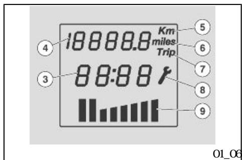
Digital display (01_05, 01_06)
Turning the ignition key "I" to "ON" activates all the segments on the multifunction LCD (this checks components correct operation) and displays the last function set after switching off the engine.
1000km
10000km
300km
5
aprilia
CAUTION
THE SERVICE ICON IS DISPLAYED ON THE LOD AFTER RIDING THE FIRST 1000 KM AND THEN AFTER EVERY 10000 KM THE SERVICE ICON FLASHES FOR ABOUT 5 SECONDS AFTER THE IGNITION CHECK 300 KM TO THE NEXT SERVICE ONCE THE MILEAGE FOR A SERVICE HAS BEEN REACHED. THE ICON WILL BE STEADILY ON UNILT THE SERVICE IS CARRIED OUT. IF THIS OCCURS TAKE YOUR SCCRTER TO AN OFFICIAL APRILIA DEALER TO CARRY OUT MINIENANCE OPERATIONS SPECIFIED IN THE SCHEDULED MINIENANCE TABLE
"2"
MDE
Several functions can be selected and viewed on the display using the MODE button "2" on the controls on the left hand side of the handlebar.
- "3"
The segments of the multifunction LCD display are the following:
-
- digital clock "3",
- odometer indicator "4",
- unit of measure in km"5",
- km "5"
- "6"
- "7"
- "8"
- "9"
- - unit of measure indicator in miles
- "6"
- trip odometer indicator "7"
- scheduled maintenance service in indicator "8"
- fuel gauge "9".
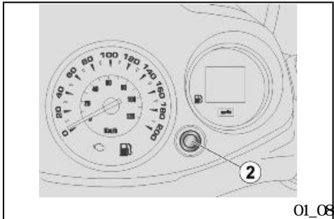
(01_07, 01_08)
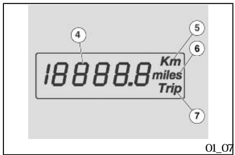
Setting the total and trip odoneters (01_07, 01_08)
DIGITAL COOMETER
These are the segments of the digital odometer functions on the LCD display:
6 Icon to display trip odometer, six digits «4», icon showing unit of measure in km «5», icon showing unit of measure in miles «6».
"4" km 5" "6"
MDE 2
Pressing the MODE button «2» displays in sequence the modes:
- Trip odometer
-TRP - Battery voltage
RESETTING THE TRIP ODOMETER
-MOE "2"
-MDE "2" 3
- Press the MODE button "2" to select the trip odometer function
- Press and hold the MDE button "2" for more than three seconds.
NOE
THIS ONLY RESEES THE FUNCTION IS PLAYED
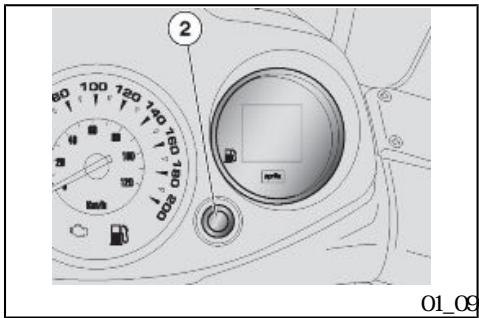
/ (01_09)
Clock/date display (01_09)
CAUTION
THE CLOCK WILL ONLY BE DISPLAYED ONLY WHEN THE VEHICLE HAS BEEN STARTED
- MODE "2"
MDE "2" 3
MODE
MOE 23
- MODE "2"
3
clock adjustment:
Press the MODE button "2" to select the TRIP function
- Press and hold the MDE button "2" for more than three seconds to activate the clock adjustment.
The first adjustment to be made is the hours. Press the MODE button "2" repeatedly to set the desired hour.
- Pressing the MDE button "2" for more than three seconds activates the minutes adjustment.
To adjust the minutes press the MODE button"2' until the desired minutes are displayed
Once the clock has been adjusted do not press any key for three seconds to leave this function
NEE
THE CLOCK CAN BE SET ONLY WHEN THE ENGINE IS OFF OR THE VEHICLE IS AT A STANStill AND WITH OR WITHOUT THE ENGINE RUNNING
(01_10)
《1》
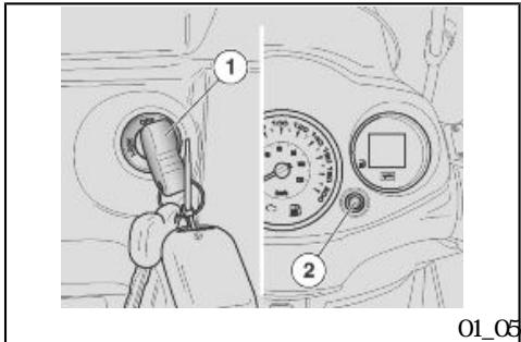
Key switch (01_10)
The ignition switch "1" is found on the right side, near the headstock.
NEE
THE KEY ACIIVATES THE IGNITION STEERING LOCK SWITCH THE SADDLE LOOK AND THE GLOVE BOX LID
NEE
TWO KEYS ARE SUPPLIED WITH THE VE HOLE (A SPARE ONE).
KEEP THE SPARE KEY IN A DIFFERENT PLACE, NOT WITH THE VEHICLE
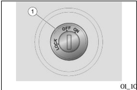
QF
ON
LOK
OR: The engine and lights cannot be set to work. The ignition key can be extracted
ON The engine and lights can be set to work. The key cannot be extracted
LOCK The steering is locked. The engine and lights cannot be set to work. The ignition key can be extracted
Locking the steering wheel
To lock the steering
- Turn the handlebar fully to the left.
- «LOCK» Turn the ignition key to the "LOCK" position
CAUTION


AVOIDING LOSING CONTROL OF THE VEH CLE, NEVER TURN THE KEY TO "LOCK" WHILE RIDDING

(01_11)
Switch direction indicators (01_11)
《2》
Move the switch "2" to the left, to indicate a left turn. Move the switch "2" to the right, to indicate a right turn. Pressing the central part of the switch deactivates the turn indicator. While the vehicle is in motion the system automatically deactivates the turn indicator system after 40 seconds or 500m
《2》
40
500m
NEE
"ON
ELECTRICAL COMPONENTS FUNCTION ONLY
WENT THE IGNITION KEY IS SET TO "ON"
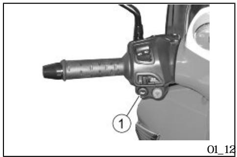
(01_12)
《1》
Hbrn button (01_12)
Pressing the button "1" activates the horn
"ON
NOE
ELECTRICAL COMPONENTS FUNCTION ONLY
WEN THE IGNITION KEY IS SET TO "ON"

(01_13)
《3》 《B》
《A》
《C》
Light switch (Ol_13)
If the light switch "3" is set to "B", this activates the high-beam light; if it is set to "A", this activates the low beamlight.
Turning the light switch to "C" the high-beamlight flashes.
NOE
"ON
ELECTRICAL COMPONENTS FUNCTION ONLY
WENT THE IGNITION KEY IS SET TO "ON"
NOE
ONCE THE LIGHT SWITCH IS RELEASED FROM THE PASSING MODE IN "C"THE HIGHBEAMLIGHT STOPS FLASHING
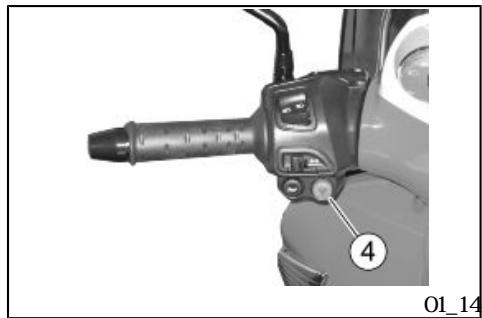
(01_14)
《4》
Emergency flashing light button (01_14)
Using the HAZARD switch "4" it is possible to activate/deactivate the hazard lights.
《ON》
ACTIATION
4
With the ignition switch in "ON".
《FF》
Press to activate the four arrows. Now it is possible to turn the ignition switch to "OFF" and withdraw the key.
DEACTI VAI I ON
《ON
Insert the key in the ignition switch and turn it to "ON, press the HAZARD switch again to deactivate the system
NOE
ACTIVATE AND DEACTIVATE THE HAZARD LIGHTS ONLY WHEN THE IGNITION KEY IS SET TO "ON"
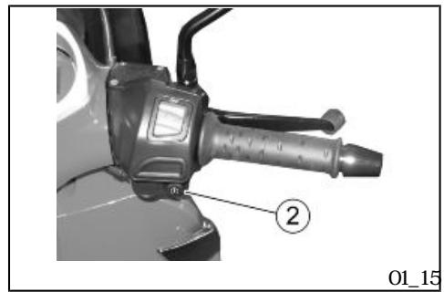
(01_15)
《2》
"ON
Start-up button (01_15)
By pressing the starter button «2», the starter motor makes the engine rotate.
NOE
ELECTRICAL COMPONENTS FUNCTION ONLY
WEN THE IGNITION KEY IS SET TO "ON"
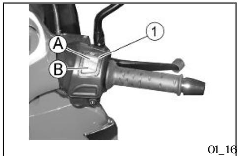
(01_16)
《1》 B RUN
A> CFF
Engine stop button (01_16)
It acts as an engine cut-off or emergency stop switch Wth the switch «1» in «B» RN it is possible to start the engine; pressing the switch when set to «A» QF will stop the engine.
| NOIE | |
| "ON" | ELECTRICAL COMPONENTS FUNCTION ONLY WEN THE IGN KEY IS SET TO "ON" |
| CAUTION | |
| DO NOT ACTIVATE THE ENGINE STOP SWITCH WHILE RUDING THE VEHICLE | |
| CAUTION | |
| <ON> | WHITHE ENGINE OFF AND THE IGN ON SWITCH SET TO <ON> THE BATTERY MAY GET DISCHARGED WITH THE ENGINE OFF AND AFTER IT STOPS TURN THE IGN ON |
| <OFF> | SWITCH TO <OFF>. |
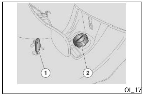
(01_17)
《1》
《1》
Fuel tank (01_17)
To reach the fuel tank cap
- Insert the key "1" into the fuel tank compartment lock
- Turn the key "1" anticlock wise.
- Unscrewthe tank cap "2".
(01_18)

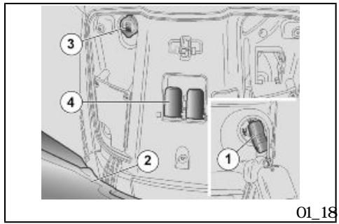
Power supply socket (01_18)
There is a 12V socket inside of the glovebox "3" and a lever "4" to open the saddle manually.
The 12V socket can be used to power equipment with a max inimum power of 180W (nobile telephones, hand lamps, etc.).
CAUTION
USING THIS SOCKET FOR A LONG PERIOD CAN RESULT IN A FULLY DISCHARGED BATTERY.
(01_19)
《1》
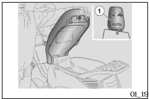
The saddle (01_19)
- To unlock the saddle autonatically: press the button "1" on the re nate control.
- To unlock the saddle manually: open the glovebox.
- Pull the lever to unlock the saddle manually.
- To lock the saddle, lower and press (without force) to trip the lock.
| CAUTION | |
| BEFORE RATING MAKE SURE THAT THE SADDLE IS CORRECTLY LOOKED INTO POStION | |
| (01_20, 01_21) | Identification (01_20, 01_21) |
| Chassis number | |
| The chassis number is stamped on the central chassis bar. To read the chassis number it will be necessary to open the glove-box and remove the snap-on protection. | |
| Chassis No: | |
| Engine number | |
| The engine number is stamped near the rear shock absorber lower sup port. | |
| Engine No: | |
Write down the chassis and engine numbers in the specific space in this manual.
The chassis number can be used to order spare parts.

NOE

ALtering Identificaiton NUMBERS CAN BE SERIOUSLY PUNISHED BY LAW PAR TICULARY MIDIFYING THE CHASSIS NUMBER WILL IMMEDIATELY INVALIDATE THE WARRANTY.
(01_22)
•
《1》 OFF
•
《2》
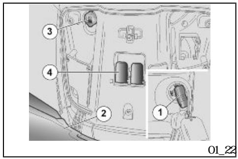
Rear top box opening (01_22)
Thanks to the glove-box it is not necessary to carry bulky items with you after parking your scooter.
- Insert and press the key into the lock «1».
The cover 2 of the glovebox will open automatically.
SCARABEO 250 i.e.

Q
Chap 02
Use
Checks


CAUTION


BEFORE SETTING OFF, ALWAYS CARRY OUT A PRELIMINARY CHECK OF THE VEHICLE FOR CORRECT AND SAFE OPERATION FAILURE TO DO SOMAY RESULT IN SEVERE PERSONAL INJURY OR VEHICLE DAMAGE
aprilia
DO NOT HESITATE TO CONTACT AN OFFICIAL aprilia Dealer IF YOU DO NOT UNDERSTAND HOWSONE CONTROLS WORK OR IF A MALFUNCTION IS DETECTED OR SUSPECTED
CHECKS DON'T TAKE LONG AND RESULT IN SIGNIFICANILY ENHANCED SAFETY.
PRE-RIDE CHECKS
Front and rear disc brake
Check operation Check brake lever travel when stationary and brake fluid level. Check for leaks. Check brake pads for wear. If necessary top-up with brake fluid
Brake levers
Check they function smoothly.
Lubricate the joints if necessary.
| Throttle grip | Check that the throttle functions smoothly and can be fully opened and closed in all steering positions. Adjust and/or lubricate if necessary. | |
| Engine oil | Check and/or top-up as required | |
| Wheels/ tyres | Check that tyres are in good conditions. Check inflation pressure, tyre wear and potential damage. | |
| Steering | Check that the rotation is uniform smooth and there are no signs of clearance or slackness. | |
| Centre and side stands | Check that it works smoothly and it goes back to its normal position when the springs are released. Lubricate couplings and joints if necessary. | |
| Fastener elements | Check that the fastener elements are not loose. Adjust or tighten if necessary. | |
| Fuel tank | Check the level and refill if necessary. Check the circuit for leaks or obstructions. |
| Check that the tank covers correctly. | |
| Coolant | Fluid level inside the expansion tank should be between the «MIN» and «MAX» reference marks. |
| engine stop switch | Check function |
| Lights, warning lights, injection telltale light, horn and electrical devices | Check the correct operation of the horn and lights. Replace the bulbs or intervene in case of failure. |
| Injection pump | Check that it works properly. |
Refuelling
CAUTION


FUEL USED TO DRIVE EXPLOSION ENGINES IS HIGHLY INFLAMMABLE AND CAN BECOME EXPLOSIVE UNDER SPECIFIC CONDITIONS.
CARRY OUT REFILLING AND MINIENANCE PROCEDURES IN A WELL-VENILATED PLACE AND WITH THE ENGINE OFF.
DO NOT SMKE WHILE REFUELING OR WHEN CLOSE TO FUEL VAPOURS,AVOID CONTACT WITH NAKED FLAMES,SPARKS OR ANY OTHER SOURCE THAT MAY CAUSE FUEL TO CATCH FIRE OR EXPLODE
AVOID SPILLING FUEL OFF THE FILLER AS IT MAY CATCH FIRE IN CONTACT WITH THE ENGINE HOT SURFACES. IN CASE OF ACCIDENTAL FUEL SPILLS, CHECK THAT THE AREA IS COMpletely Dry BEFORE STARTING THE VEHICLE
FUEL EXPANDS WHEN EXPOSED TO HEAT OR SUN RAYS, THEREFORE BE CAREFUL AND DON'T REFILL THE TANK UP TO THE TOP.
CLOSE THE CAP ADEQUATELY AFTER RE FUELLING BE CAREFUL FUEL DOES NOT GET INTO CONTACT WITH YOUR SKIN DO NOT INHALE VAPOURS OR SWALLOWFUEL DO NOT TRANSFER FUEL FROM ONE CONTAINER TO ANOTHER USING A HOSE
CAUION

DONT DISPOSE OF FUEL INTO THE ENVIRONMENT
CAUION

KEEP OUT OF THE REACH OF CHILDREN
CAUTION


PEIROL DAMGES THE PLASTIC PARIS OF THE BODWORK


DO NOT USE THE SCOOTER TO THE COMPLEIE EXHALSION OF THE FUEL; IN THE EVENT THAT THIS SHOULD OCCUR, DO NOT ATTEMPT TO START THE ENGINE. TURN THE KEY SWITCH TO OFF AND TOP-UP THE TANK AS SCON AS POSSIBLE. THE FAIL URE TO FOLLOW THESE GUIDELINES COULD CAUSE DAMAGE TO THE FUEL PUMP AND/OR THE CATALYSER
OFF
NOMM
95 NORM
85 Use unleaded premium petrol only with minimum octane rating of 95 (NORM) and 85 (NOMM)
Characteristic
1321
Fuel tank capacity (reserve included)
31
1321
tank reserve
31
(02_01)
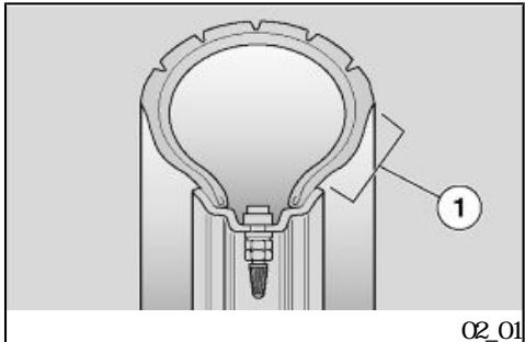
Tyre pressure (02_01)
TYRES
This vehicle is fitted with tyres without inner tubes (Tubeless).
CAUTION


CHECK FREQUENILY TYRE PRESSURE WITH TYRES AT AMBIENT TEMPERATURE
THE MEASUREMENT MAY BE INCORRECT IF TYRES ARE WORM CHECK TYRE PRESSURE MINLY BEFORE AND AFTER A LONG JOURNEY AN OVERINFLATED TYRE WILL PROVIDE A HARSH RIDE AS SURFACE UN EVENNESS IS NOT CUSHONED AND IS SENT TO THE HANDLER, THIS REDUCING GRIP AND STABILITY SPECIALLY WHEN CORNERING
"1"
CONVERSELY, AN UNDER INFLATED TYRE WILL EXTEND THE CONTACT PATCH TO INCLUDE A LARGER PORITION OF THE TYRE SIDEWILS «1», IF SQ THE TYRE COULD SLIP ON OR EVEN GET DETACHED FROM THE RIM RESULTING IN LOSS OF CONTROL OVER THE VEHICLE THE TYRE MIGHT EVEN JUMP OFF THE RIM UNDER HARD BRAKING EVENTUALLY THE VEHICLE MIGHT SKID IN A BEND INSPECT THREAD SURFACE AND CHECK IT FOR WEAR BADLY WORN TYRES ADVERSELY AFFECT TRACTION AND HANDLING SOME TYRE TYPES HOMO LOGATED FOR THIS VEHICLE FEATURE
5mm
WEAR INDICATORS. THERE ARE SEVERAL TYPES OF WEAR INDICATORS.
CONSULT YOUR DEALER ON METHODS TO CHECK WEAR CARRY OUT A VISUAL IN SPECTION FOR TYRE CONSUMPTION REPLACE TYRES IF WORN OLD TYRES THAT ARE NOT FULLY WORN CAN GET HARD RESUING IN LACK OF GRIP. REPLACE TYRES IF THIS OCCURS. REPLACE TYRES WHEN WORN OR IF THE TREAD HAS A HOLE BIGGER THAN 5MM BALANCE THE WEELS AFTER A TYRE IS MINDED. USE ONLY TYRE SIZES INDICATED BY THE MANU FACTURER DON'T FIT TYRES WITHIN NER TUBE SONS ON RIMS FOR TUBELESS TYRES OR VICE VERSA CHECK THAT THE IN FLATION VALVES HAVE THEIR CAPS FITTED IN ORDER TO AVOID UNEXPECTED FLAT TYRES.
aprilia
REPLACEMENT, REPAIR, MAINTENANCE AND BALANCING OPERATIONS ARE HIGHLY IMPORIENT AND SO THEY SHOULD BE CARRIED OUT USING THE SPECIFIC TOOLS AND WITH THE ADEQUATE KNOWLEDGE. IT IS THEREFORE ESSENTIAL TO HAVE YOUR TYRES AND WHEELS SERVICED AT AN OF FICIAL aprilia Dealer OR A SPECIAL ISED TYRE WORKSHOP. NEWTYRES CAN BE COVERED BY A SLIPPERY COAT. RULE WITH CAUTION DURING THE FIRST KILO METRES. DO NOT APPLY UNSUITABLE LIQUIDS ON TYRES.
| 190 kg | CAUTION |
| NEVER EXCEED THE MAXIMUM WEIGHT AL LOVED TO BE TRANSPORIED OVERLOADING THE SCOOTER MAY RESULT IN LACK OF STABILITY, POOR HANDLING AND TYRE DAMAGE | |
| Characteristic | |
| MAXload | |
| 190 kg | |
| 2.2 bar | Characteristic |
| Front tyre pressure (rider only) | |
| 2.2 bar | |
| Rear tyre pressure (rider only) | |
| 2.2 bar | |
| 2.2 bar | Front tyre pressure (passenger + rider) |
| 2.2 bar | |
| 2.2 bar | Rear tyre pressure (passenger + rider) |
| 2.3 bar | |
| 2.3 bar |
(02.02, 02.03)
Shock absorber adjustment (02_02, 02_03)
Front and rear suspension inspection Check oil and oil seal of front suspension following the instructions on the scheduled maintenance table.
According to the indications in the scheduled maintenance table, carry out the following checks:
- With the front brake lever pulled, press repeatedly on the handlebar lowering the fork.
The travel should be progressive and there should be no signs of oil on the stents.
- Check that all organs are tightened and the joints of the front and rear suspension work properly.
- With the front brake lever pulled, press repeatedly on the handlebar lowering the fork.
The travel should be progressive and there should be no signs of oil on the stents.
- Check that all organs are tightened and the joints of the front and rear suspension work properly.
The travel should be progressive and there should be no signs of oil on the stents.

aprilia
CAUTION

TO HAVE THE FRONT SUSPENSION QL CHANGED TAKE YOUR VEHICLE TO AN OF ficial aprilia Dealer WO WLL PRO VIDE A PRECISE AND PROMPT SERVCE
CAUTION

IN CASE OF FAILURE OR WENT THE INTERMENION OF SPECIALISED PERSONEL
aprilia
REAR SUSPENSION ADJUSIMENT
The rear suspension consists of one double-acting shock absorber (compression/rebound damping), with silent-block engine mount.
The shock absorber features a ring nut to adjust the spring preloading. The manufacturer has set the standard suspension adjustment for a rider weighing about 70 kg. For other weights, use a hook spanner (supplied) on the ring nut "1" to define the ideal running settings.
70kg
"1"
- Turn the adjustment ring nut «1» (shock absorber spring preloading adjustment).
•
《1》
NEE
CARRY OUT THE ADJUSTMENT ON BOIH REAR SHOCK ABSCRERS.
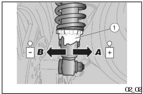
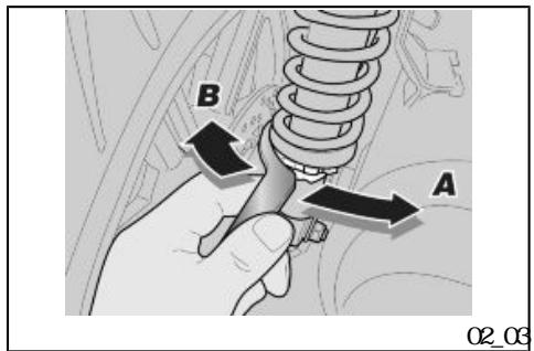
A
B
Turn the ring nut in direction A Increase spring preloading The vehicle suspension is very hard. To be used on roads with even or ordinary surfaces and when riding with passenger.
Turn the ring nut in direction B Decrease spring preloading The vehicle suspension is very soft. To be used on uneven roads and when riding without passenger.
Running in
Engine run in is essential to ensure engine long life and correct operation If possible, ride on roads with lots of bends and/or slopes to test that the engine suspensions and brakes perform efficiently.
Follow these indications:
- Do not twist the throttle grip fully at lowrpm
0-100km 100 km
0-500km 500 km 80%
•
1000 km

whether during or after run-in
- 0-100 km(0-62 miles) During the first 100 km(62 miles) step carefully on the brakes to avoid rough and long braking. That is to permit the adequate adjustment of the pad friction material to the brake disc.
- 0-500 km(0-312 miles) During the first 500 km(312 miles) do not ride the scooter over 80% of the predetermined maxium speed.
AVOID KEEPING A CONSTANT SPEED ALONG LONG SECTIONS OF ROAD
After the first 1000km(625 miles), gradually increase the speed until the maximum performance is reached
CAUTION

ALWAS SIGNAL CHANGES IN DIRECTION WITH THE APPROPRIATE DEVICES AND WELL IN ADVANCE, AVIDID ABRUCT AND DANGEROUS MANCEUMES. TURN OFF THE DEVICES IMMEDIATELY AFTER THE CHANGE IN DIRECTION RIDE WITH EXIRENCE CAUTION WHEN OVERTAKING OR BEING OVERTAKEN BY OTHER VEHICLES. WENIT RAINS, SPRAY CALSED BY LARGE VEH CLES REDUCES VISIBILITY, AIR SHFIS

1000 km
1000 km
MAY CAUSE LOSS OF CONTROL ON YOUR VEHICLE
CAUTION

AFTER THE FIRST 1000 KM(625 MILES) IN OPERATION PERFORM THE CHECKS INDICATED IN THE SCHEDULED MINIE NANCE CHART TO AVOID INJURIES TO YOURSELF, OTHERS AND/OR DAMAGING THE VEHICLE
NOTE
ONLY AFTER THE FIRST RUN IN 1000 KM (625 MILES) IT IS POSSIBLE TO ATTAIN THE BEST SPEED AND ACCELERATION PERFORMANCE OF YOUR SCOOTER
(02.04, 02.05)
02_06, 02_07, 02_08, 02_09
02_10
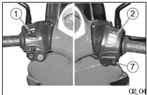
Starting up the engine
(02.04, 02.05, 02.06, 02.07,
02.08 02.09 02.10
CAUTION


EXHAUST FUNES CONTAIN CARBON MNOX IDE, AN EXTERELY HARMFUL SUBSTANCE IF INALED NEVER START THE ENGINE IN CLOSED OR NOT WELL-VENTILATED ROOMS.
· 《1》
2 《RUN
3 《CN

《4》
FAILURE TO OBSERVE THIS WARNING COULD LEAD TO UNCONSCIOUS AND EVEN DEATH CAUSED BY SUFFOCATION
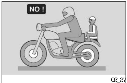
DONT CLIM ON THE VEHICLE TO START IT UP. DONT START THE ENGINE WALE THE VEHICLE RESTS ON ITS SIDE STAND
- To start the engine, rest the vehicle on its centre stand and check that the side stand has been completely retracted to its position
- Make sure that the light switch "1" is set to "low bean".
- Set the engine cut-off switch "2" to "RUN".
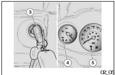
- Turn the key "3" and set the ignition switch to "ON.
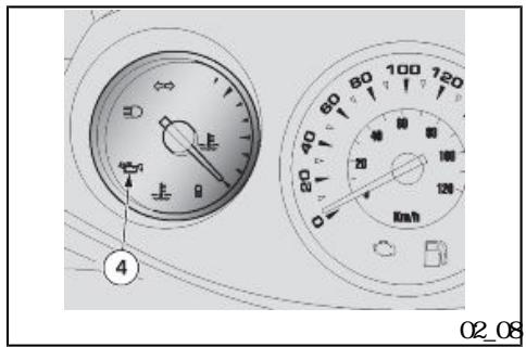
CAUTION

NOW
THE ENGINE OIL PRESSURE VARNING LIGHT "4" TURNS ON THE INSTRUMENT PANEL AND REMAINS SO UNIL THE ENGINE STARIS UP.
EFI 《5》
3
aprilia
THE ENGINE FUEL INJECTION (EFI)
WARNING LIGHT "5" REMAINS ON FOR
THREE SECONDS ON THE INSTRUMENT
PANEL AFTER ALL THE OTHER WARNING
LIGHTS HAVE TURNED OFF.
3
IF THIS WORNG LIGHT DOES NOT TURN
ON OR AFTER THREE SECONDS THE WARM
ING LIGHTS DO NOT TURN OFF, CONTACT
AN OFFICIAL APRILIA DEALER
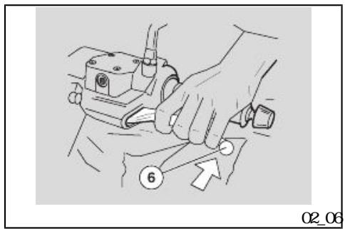
6
.
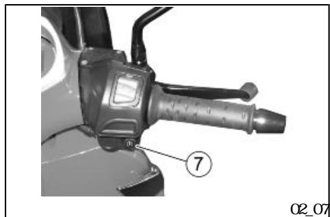
《7》
-
Block one wheel at least operating one brake lever "6". If the engine fails to start, it means there is no current in the ignition relay and the engine does not start.
-
Press the starter button "7" but do not accelerate and release it as soon as the engine starts.
( x - 2x) t - xy^2 = ( x - 2x) f^ t
( x - 2x) t - xy^2 = ( x - 2x) f^ t
5 10
10
10
NEE
IF THE VEHICLE IS NOT USED FOR A LONG TIME FOLLOW THE PROCEDURE FOR STARTING THE ENGINE AFTER PROLONGED INACIVITY
NEE
TO AVOID EXCESSIVE BATTERY CONSUMP
TION DO NOT HOLD DOWN THE STARTER
BUTTON FOR MRE THAN FIVE SECONDS
(TEN WEN STARIING UP AFTER PRO

"7"
LONGED INACIVITY. IF THE ENGINE FAILS TO START AFTER THIS TIME, WIT TEN SECONDS AND REPEAT THE PROCEDURE
CAUTION

NEVER PRESS THE STARTER BUTTON "7"
WHEN THE ENGINE IS ALREADY RUNNING
DOING SOME DAMAGE THE STARTER MOTOR

"4"
aprilia
CAUTION

WEN THE ENGINE IS RUNNING THE ENGINE OIL PRESSURE WARGING LIGHT "4" SHOULD TURN OFF. IF THE WARGING LIGHT STAYS ON OR TURNS ON WHILE THE ENGINE IS WARGING PROPERLY THIS MEANS THAT THE OIL PRESSURE IN THE CIRCUIT IS NOT ENOUGH SHOULD THIS OCCUR, STOP THE ENGINE AT ONE AND CONTACT AN aprilia Official Dealer. NEVER USE THE VEHICLE WITH LOW ENGINE OIL SOAS TO AVOID DAMAGING EN GINE PARTS.

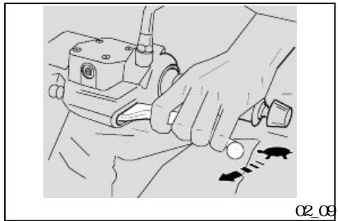
- Keep at least one brake lever operated and accelerate only when setting off.
CAUTION


DONOT SET OFF SUDDENLY WENTHE ENGINE IS COLD TOMMINSE THE EMISSION OF AIR POLLUING SUBSTANCES AND FUEL CONSUMPTION WARMUP THE ENGINE BY RIDING THE FIRST KILONEIRS AT A LIMITED SPEED

To set off:

Get on the scooter and keep at least one foot on the ground for stability.
- Adjust the angle of rear-view mirrors adequately.

CAUTION

WH THE VEHICLE AT A STAND STILL, PRACTICE USING THE REAR VIEW MIRROR. THE MIRROR REFLECTING SURFACE IS CONTEX SO OBJECTS MAY SEEM FAR. THER THAN THEY REALLY ARE THESE MIRROR OFFER A WIDE ANGLE VIEW AND ONLY EXPERIENCE HELPS YOU JUDGE THE
DISTANCE SEPARATING YOU AND THE VE HOLE BEHIND
- Release the brake lever and accelerate, gradually twisting the throttle grip the scooter starts nowing forward

CAUTION

DONT SET OFF SUDDENLY WENTHE ENGINEIS COLD
TO MNMSE THE EMISSION OF AIR POLLUING SUBSTANCES AND FUEL CONSUMPTION WARM UP THE ENGINE BY RIDING THE FIRST KILOMESES AT A LIMITED SPEED

CAUTION

NEVER ACCELERATE AND DECECELATE RE PEATEDLY AND CONTINUUSLY AS YOU MAY INADMERIENILY LOSE CONTROL OF YOUR VEHICLE
IF YOU HAVE TO BRAKE, DECELERATE AND OPERATE BOTH BRAKES TO OBTAIN A UNFORMBRAKING CAREFULLY ACTIVAT
ING THE BRAKING PARIS IN AN ADEQUATE MINER
OPERATING ONLY EITHER THE FRONT OR THE REAR BRAKE SIGNIFICANLY DECREASES THE BRAKING POWER AND A WHEEL MAY GET BLOCKED RESULTING IN LACK OF GRIP. IN CASE OF STOP INAS CENT, FULLY DECELERATE AND ONLY USE THE BRAKES TO KEEP THE VEHICLE STOPPED USING THE ENGINE TO KEEP THE VEHICLE STOPPED MAY CAUSE THE VARIATOR TO OVERHEAT.

CAUTION

BEFORE GETTING INTO A BEND REDUCE SPEED OR BRAKE; WHILE BENDING RIDE AT THE SAME MODERAIE AND CONSTANT SPEED OR Slightly Accelerate; DO NOT BRAKE IN EXCESS: THERE IS HIGH RISK OF SKIDDING
BRAKING CONTINUELY WHILE GONG DOWHILL MAY RESULT IN FRICTION GASKET OVERHEATING AND CONSEQUENIALLY IN POOR BRAKING TAKE ADVANTAGE OF THE ENGINE COMPRESSION USING THE BRAKES ALTERNATIVELY. WHEN GONG DOWHILL NEVER RIDE WITH THE ENGINE OFF. WHEN RIDING ON WET SURFACES OR WI/WH POOR GRIP (SNOW ICE, MD ETC) AT A MODERATE SPEED AVIDING Sudden BRAKING OR MACEUMES THAT
MAY LEAD TO LACK OF GRIP AND CONSE GENILY TO FALLS. PAY ATTENTION TO OESTACLES ON OR VARIATIONS IN THE ROAD SURFACE UNEW ROAD, RUIS, DRAINS, TRAFFIC SIGNS PAINTED ON THE ROADS, FIPEWARK METAL SHEETS MAY BECOME SLIPPERY WENIT RAINS. CROSS OVER THEM WITH EXTREME CAUTION RIDE CAREFULLY AND INLINE THE VEHICLE THE LEAST POSSIBLE
Difficult start up
The fuel supply system can control ignition based on the engine condition (hot/cold) or the ambient temperature and pressure.
(02_11, 02_12)
A
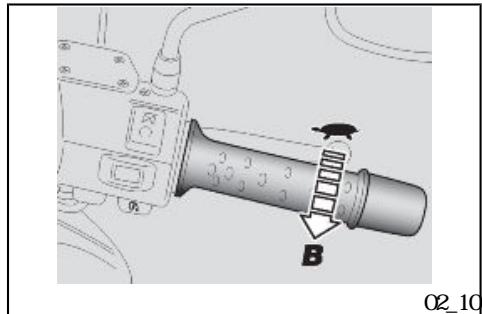
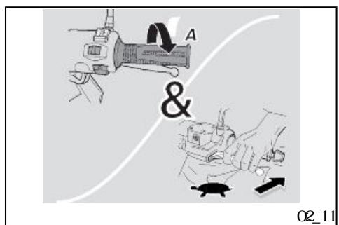
Stopping the engine (02_11, 02_12)
- Release the throttle grip (pos. A) and gradually operate the brakes to stop the scooter.
- Wile at a temporary halt, keep at least one brake operated
- Stop the scooter.

CAUTION

WENEVER POSSIBLE,AVOID ROUGH BRAKING SUDEN DECELATION AND BRAKING IN EXCESS.

CAUTION

PARK ON SAFE AND LEVEL GROUND TO PREVENT THE VEHICLE FROM FALLING
DON'T LEAN THE VEHICLE ON A WALL OR LAY ON THE GROUND
MAKE SURE THE VEHICLE AND SPECIALLY ITS HOT PARIS DON'T POSE ANY RISK TO PEOPLE OR CHILDREN DO NOT LEAVE YOUR VEHICLE UNATTENDED WITH THE ENGINE ON OR THE KEY IN THE IGNITION SWITCH
DO NOT SEAT ON THE VEHICLE WEN THE STAND IS LOWERED
《OFF》
《1》 《B》
- Set the engine cut-off switch "1" to "B" "OF".
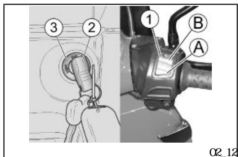

《ON》
《2》
《3》 《OF》
•
.
CAUTION

WH ENGINE OFF AND THE IGNITION SWITCH SET TO «ON» THE BATTERY MAY GET DISCHARGED
《3》 《LOK》
《2》
《2》
DON'T LEAVE THE KEY "2" INSERTED IN THE IGNITION SWITCH
CAUTION
NOE
WEN THE STEERING LOCK IS ENGAGED THE ENGINE CAN NOT BE STARTED IF THE KEY IS NOT INSERTIED IN THE GLOWBOX
Catalytic silencer
Vehicle owners are warned that the law may prohibit the following:
- the renewal of any device or element belonging to a new scooter or any other action by anyone leading to render it non-operating if not for maintenance, repair or replacement reasons, in order to control noise emission before the sale or delivery of the vehicle to the ultimate buyer or while it is used;
using the scooter after that device or element has been removed or rendered non-operating
Check the nuffler/exhaust silencer and the silencer pipes, nake sure there are no signs of rust or holes and that the exhaust system works properly.
If exhaust noise increases, take your scooter at once to an Official aprilia Dealer.
NOE
DONT TAMPER WITH THE EXHAUST SYS TEM
(02_13, 02_14, 02_15)
《4》
《5》
《6》
•
《4》
《5》
•
《7》
•
•
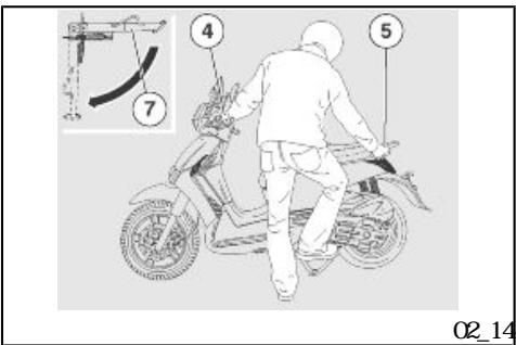

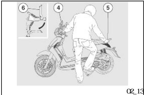
Stand (02_13, 02_14, 02_15)
CENTRE STAND
- Hold the left handgrip "4" and the passenger handgrip "5".
- Push the stand lever "6".
SIDE STAND
- Hold the left handgrip "4" and the passenger handgrip "5".
- Push the side stand "7" with your right foot, and extend it completely.
- Lean the scooter until the stand touches the ground
- Turn the handlebar fully left.
CAUTION

MAKE SURE THE VEHICLE IS STABLE
《1》
《2》
•
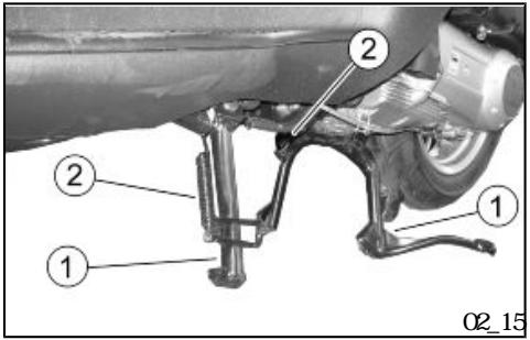
Stand checking
The rotation of the stand "1" should be free of obstacles.
Carry out the following checks:
The springs "2" should not be damaged, worn, rusty or slacken
The stand should turn freely, grease the joint if necessary.
CAUTION


FOR THE SIDE STAND ONLY RISK OF FALLING OR ROLLING OVER
NOE
THE FOLLOWING INFORMATION REFERS TO ONE STAND BUT IS VALID FOR BOTH
Suggestions to prevent theft
NEVER leave the ignition key in the lock and always use the steering lock.
Park the scooter in a safe place such as a garage or a place with guards.
aprilia "Body-Guard"
Wenever possible, use the aprilia "Body-Guard" armoured cable or an additional antitheft device.
Make sure all vehicle documents are in order and the road tax paid
Write down your personal details and telephone number on this page to help identifying the owner in case of scooter retrieval after a theft.
LAST
NAME
NAME:
AD
DRESS:
TELEPHONE
No:
IMPORTANT In many cases, stolen vehicles can be identified through data indicated in the use and maintenance manual.
(02.16, 02.17,
02_18, 02_19, 02_20, 02_21,
02_22, 02_23, 02_24, 02_25
02.26 02.27
Safe driving (O2_16, O2_17,
02_18, 02_19, 02_20, 02_21,
02_22, 02_23, 02_24, 02_25
02.26 02.27
MIN SAFETY RULES
To ride the vehicle it is necessary to comply with all legal requirements (driving license, minimum driving age, psychophysical performance, insurance, taxes and fees, registration, license plate, etc.).
You should practise using the vehicle in traffic-free areas and/or private property until you have become thoroughly acquainted with the vehicle.
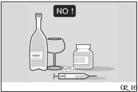
Driving under the influence of narcotic drugs or psychotropic substances dramatically increases the risk of accidents.
Do not ride your vehicle if you feel tired or drowsy and always keep safe psychophysical riding conditions.
The main cause of motorcycle accidents is users' inexperience.
NEVER lend the vehicle to beginners and always make sure that the rider complies with all necessary requirements for a safe riding.
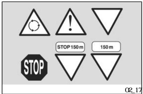
Strictly obey all national and local traffic signs and rules.
Avoid any abrupt and dangerous swerves for your own as well as others' safety (for example: rearing up on the back wheel, riding over the speed limit, etc.). Besides, always assess and bear in mind the road surface conditions, visibility, etc.
Do not knock obstacles that can damage the vehicle or cause loss of control.
Do not ride on the course of the vehicle in front just to improve your own speed.
CAUTION

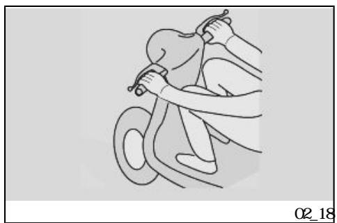
ALWAS RIDE WITH BOTH HANDS ON THE HANDLEAR AND FEET ON THE FOORESIS (OR THE RIDERS FOORESIS) IN THE ADEQUATE RIDING POSITION
Never stand on your feet or stretch yourself while riding.
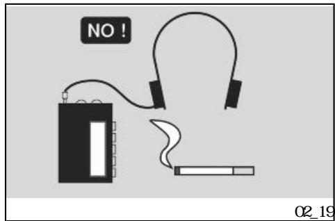
The rider should always be attentive, never get distracted or influenced by people, things or actions (never smoke, eat, drink, read, etc.) while riding.
Always use fuel and lubricants specific for the vehicle, of the type recommended in the "LUBRICANIS TA
aprilia
BLE'. Check fuel, oil and coolant frequently for correct level.
In case of an accident or after the vehicle has fallen down or suffered a sudden bump, make sure the control levers, piping cables, brake circuit and main parts of the vehicle have not been damaged.
If necessary, take the vehicle to an official aprilia Dealer to check especially the frame, handlebar, suspensions, safety components and any device the user cannot assess without the aid of a specialist.
Report any nalfunction to the engineers and/or mechanics in order to facilitate their work.
Never ride the vehicle if the damage jeopardises safety.
Do not modify the position, angle or colour of: license plate, turn indicators, lighting devices and horn
Any changes to the vehicle will void the warranty.
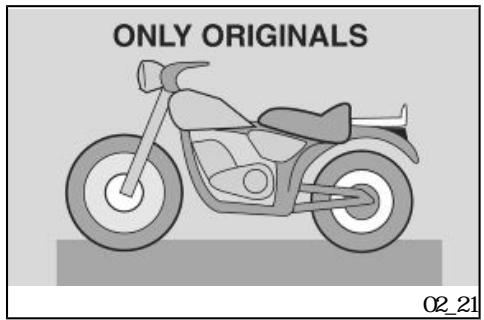
Any change introduced to the vehicle and the renewal of original parts may jeopardise the vehicle performance and therefore reduce safety or even render the vehicle inappropriate for legal riding
Comply with all national and local laws and regulations on vehicle equipment.
In particular do not introduce technical changes leading to improve performance and under no circumstances alter the original specifications of the vehicle.
Never race with vehicles.
Never ride off-road.
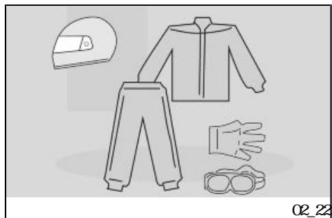
CLOTHING
Before riding off, remember to put on the helmet and fasten it correctly. Make sure it is a homologated model, that it is undamaged, of the right size and that the visor is clean
War appropriate protective clothes, preferably light-coloured and/or in reflective material. In this way you will be easily visible to other drivers, thus reducing the risk of being hit, and you will be better protected in case of falling
Always wear tight-fitting clothes without open cuffs; avoid hanging strings, belts or ties; these or any other objects should not interfere with a safe riding when getting entangled with the riding elements or due to a special movement.
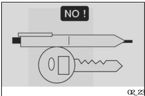
Never carry in your pockets objects that can be potentially dangerous in case of fall, like: pointed objects such as keys, pens, glass contain
ers, etc. (the same rule applies to passengers).
ACCESSIONS
User is personally responsible for the installation and use of the accessories.
While assembling accessories, make sure that they do not cover the sound or light alarm devices or affect their correct functioning. Do not limit the suspension travel or the steering angle, do not obstruct control actuation or reduce the ground clearance and inclination angle at corners.
Do not use accessories that hinder access to the controls as they may increase the reaction time in case of an emergency.
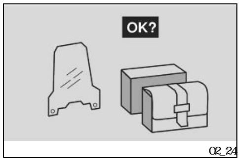
Fairings and large windshields fitted to the vehicle may cause aerodynamic forces that affect the vehicle stability while riding mainly at high speeds.
Make sure the accessory is firmand secured to the vehicle and that it does not pose any risks while riding the vehicle.
Do not add or modify electrical equipment that exceed the vehicle capacity as this may result in a sudden stop or a dangerous lack of

power required to keep the sound and light alarm devices operative.
aprilia advises using original accessories (aprilia genuine accessories).
LOADING
Do not overload your vehicle. Keep packages as close as possible to the vehicle centre of gravity and distribute load evenly on both sides to minimise imbalance. Check also that the load is firmand secured to the vehicle, mainly for long trips.
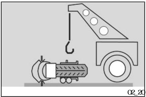
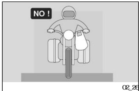
Do not hang anything from your vehicle's handlebars, mudguards or forks, such as protruding bulky, heavy and/or dangerous objects: this will slow the vehicle performance when turning and will upset the handling of your vehicle.
Do not carry packages that protrude from vehicle sides as this may hit people or objects and result in loss of control of your vehicle.
Never carry packages that are not securely fastened to the vehicle.
Do not carry packages that protrude from the luggage rack or which cover any of the sound and light alarm devices.
Never carry animals or small children on the glove-box or the luggage rack.
Never exceed the maximum weight allowed for each luggage rack
Overloading the vehicle may result in lack of stability and poor handling
SCARABEO 250 i.e.

03
Chap 03 Maintenance
aprilia


Engine oil level
Check engine oil level according to the indications in the scheduled maintenance table.
Change engine oil according to the indications in the scheduled maintenance table.
Take your scooter to an Official aprilia Dealer to have the oil changed
CAUTION

HANDLING OF PROLONGED PERIODS AND ON A REGULAR BASIS CAN CAUSE SEVERUS SKIN DAMAGE
WASH YOUR HANDS CAREFULLY AFTER HANDLING CIL
WHEN CARRYING OUT MINENCE OPERATIONS, IT IS ADMISABLE TO WAR LA TEX GLOVES.
KEEP OUT OF THE REACH OF CHILDREN
DO NOT DISPOSE OF QL INTO THE ENVIRONMENT.
CAUTION

PROCEED WITH CAUTION
| aprilia | DO NOT SPILL QL BE CAREFUL NOT TO DIRY COMPONENTS, THE WORKING OR SURROUNDING AREA THROUGHLY WASH OUT ANY QL TRACE IN THE EVENT OF QL LEAKS OR ML FUNCTION, TAKE YOUR VEHICLE TO AN Official aprilia Dealer. |
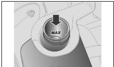
| "MAX" | NOIE DO NOT EXCEED THE "MAX MARK WHEN TOPPING UP ENGINE QL. |
| NOIE USE QL OF THE TYPE SPECIFIED IN THE RECOMMENDED PRODUCTS TABLE | |
| (03_01) | Engine oil level check (03_01) |
| · | Rest the vehicle on its centre stand |
| CAUTION | |
| PARK THE VEHICLE ON SAFE AND LEVEL GROUND |
CAUTION


THE ENGINE AND THE EXHAUST SYSTEM COMPOENIS CAN GET VERY HOT AND REMAIN SO FOR SOME TIME EVEN AFTER THE ENGINE IS TURNOFF. WEAR INSULATING GLOVES BEFORE HANDLING THESE PARIS OR WIT UNIL THE ENGINE AND THE EXHAUST SYSTEMCOOL DOWN
- Stop the engine and let it cool off so that the oil in the crankcase flows down and cools as well.
NEE
FAILURE TO FOLLOW THESE OPERATIONS MAY RESULT IN AN INCORRECT READING OF THE ENGINE CIL LEVEL.
"1"
- Unscrew and take out the measuring cap dipstick "1".
Clean the area in contact with oil with a clean cloth - Screwthe cap-dipstick "1" fully down into its tube
2".
Pull out the cap-dipstick "1" again and read the oil level on the cap-dipstick:
.
"1"
2
"1"
MAX = naxim numlevel;
MN = niri numl level.

$$ \mathbf {M} \mathbf {X} = $$
$$ \mathbf {M N} = $$
$$ \begin{array}{c c} \text {M A X} & \text {M I N} \end{array} $$
$$ " M X $$
$$ 2 0 0 \mathrm {c m} ^ {3} $$
The difference between "MAX" and "MIN" is about 200 cm²
The level is correct when it is close to the MAX level marked on the measuring dipstick

MAX 《MIN
- Top-up if necessary.
CAUTION

IN ORDER TO AVOID DAMAGING THE ENGINE, CIL LEVEL MIST NEVER EXCEED THE «MAX» MARK OR FALL BELOW THE «MIN» MARK
"2
"1"
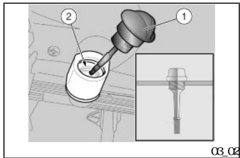
(03_02) Engine oil top-up (03_02)
1
Pour a little oil through the dipstick tube "2" and wait one minute so that the oil flows uniformly into the crankcase.
- Check oil level and top-up if necessary.
- Do so with small quantities of oil at a time until the specified level is reached

After finishing this operation, screw and tighten the tap/dipstick "1".
CAUTION

DON'T RIDE THE VEHICLE WITH INSUFICIENT LUBRICATION OR WITH CONMAINED OR INCORRECT LUBRICANTS ASTHIS ACCELERATES THE WEAR AND TEAROF THE MOING PARTS AND CAN CAUSEIRRELEVABLE DAMAGE
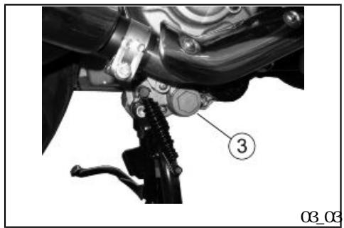
(03_03) Engine oil change (03_03)
Park the vehicle on its centre stand.

CAUTION

PARK THE VEHICLE ON SAFE AND LEVEL GROUND

CAUTION

THE ENGINE AND THE EXHAUST SYSTEM COMPOENIS CAN GET VERY HOT AND REMAIN SO FOR SOME TIME EVEN AFTER THE ENGINE IS TURNOFF. WEAR INSULATING GLOVES BEFORE HANDLING THESE
•
- Stop the engine and let it cool down. This will allow the oil to settle into the crankcase and cool down
NOE
FAILURE TO FOLLOW THESE OPERATIONS MAY RESULT IN AN INCORRECT READING OF THE ENGINE CIL LEVEL.
aprilia
•
"1"


Take your scooter to an Official aprilia Dealer to carry out the replacement.
- Unscrew and remove the cap-dipstick "1".
- Unscrew and remove the engine oil cartridge filter.
CAUTION


RIDING THE VEHICLE WITHINSUFFICIENT LUBRICATION OR CONTAMINATED OR NOT RECOMMENDED LUBRICANS ACCELERATES THE WEAR AND TEAR OF MONG PARIS AND CAN CAUSE IRRETRIREVALE DAMAGE

aprilia aprilia

AS USED QL HAS SUBSTANCES HARMFUL TO THE ENVIRONMENT, TAKE YOUR SCOOTER TO AN OFFICIAL APRIILA DEALER TO HAVE THE QL CHANGED THESE CENTRES CAN CARRY OUT ENRONNTALLY-FRIENDLY DISPOSAL OF USED QL IN COMPLIANCE WITH REGULATIONS IN FORCE
3
O
"3
"2" 1100cc
"1"
"1"
"MAX
- Unscrew and remove the oil drain plug "3" and allow all the engine oil to drain out.
- Fit a new cartridge filter oil and take special care to lubricate the sealing Oring of the filter with oil.
- Screwin and tighten the engine oil drain plug "3".
- Refill through the filling hole "2" with about 1100 cc of engine oil.
- Screw on and tighten the oil level dipstick "1".
- Start the scooter and allow to run for a few minutes. Stop the engine and let it cool down. Check the engine oil level again using the dipstick "1" and top up, if necessary, without exceeding the MAX level.
Recommended product:
Use new oil of the type specified in the recommended products table at every top-up or change.
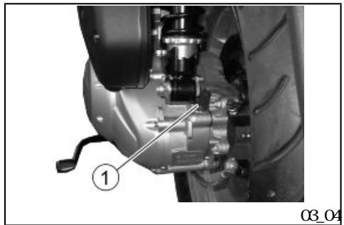
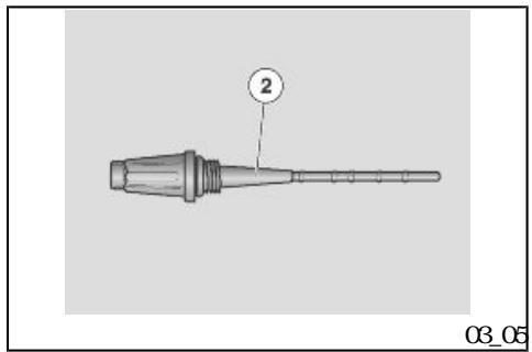
(03_04) Hbf oil level (03_04, 03_05)
Check the transmission oil level according to the indications in the scheduled maintenance table.
CAUTION


HANDLING QIL FOR PROLONGED PERIODS AND ONA REGULAR BASIS CAN CAUSE SE RICUS SKIN DAMAGE
WASH YOUR HANDS CAREFULLY AFTER HANDING OL
WHEN CARRYING OUT MINIENANCE OPERATIONS, IT IS ADMISABLE TO WEAR LA TEX GLOVES.
KEEP OUT OF THE REACH OF CHILDREN
DO NOT DISPOSE OF QL INTO THE ENVIRONMENT
CAUTION


PROCEED WITH CAUTION
DONT SPILL CIL
BE CAREFUL NOT TO DIRTY COMPONENTS, THE WORKING OR SURROUNDING AREA
THROUGHLY WISHOUT ANY CIL TRACE
IN THE EVENT OF QIL LEAKS OR ML FUNCTIONING TAKE YOUR VEHICLE TO AN Official aprilia Dealer.
aprilia


Transmission oil level check
- Rest the vehicle on its centre stand.
CAUTION

PARK THE VEHICLE ON SAFE AND LEVEL GROUND
CAUTION

THE ENGINE AND THE EXHAUST SYSTEM COMPOENIS CAN GET VERY HOT AND REMAIN SO FOR SOME TIME EVEN AFTER THE ENGINE IS TURNOFF. WEAR INSULATING GLOVES BEFORE HANDLING THESE PARIS OR WIT UNIL THE ENGINE AND THE EXHAUST SYSTEMCOOL DOWN
《1》
1
《1》
MAX=
MIN=
"MAX

"MAX
"MIN
- Unscrew and take out the measuring tap-dipstick "1".
Clean the area in contact with oil with a clean cloth - Screwthe tap-dipstick "1" fully down into its tube.
- Extract the tap-dipstick "1" again and read the oil level on the tap-dipstick:
MAX = maxi num level;
MN = minnumlevel.
The level is correct when it is close to the MAX level marked on the measuring dipstick
CAUTION

DO NOT GO BEYOND THE MAX AND BELOW THE MIN LEVEL MARKS TO AVOID SEVERE ENGINE DAMAGE
- Top-up if necessary.
•
1


Topping-up
Pour a little oil through the dipstick tube and wait one minute so that the oil flows uniformly into the crankcase.
- Check oil level and top up if necessary.
- Do so with small quantities of oil at a time until the specified level is reached
After finishing this operation, screwin and tighten the cap-dipstick "2".
Use new oil of the type specified in the recommended products table at every top-up or change.
CAUTION


RIDING THE VEHICLE WITH INSUFFICIENT LUBRICATION OR CONTAMINATED OR NOT RECOMMENDED LUBRICANS ACCELERATES THE WEAR AND TEAR OF MONG PARTS AND CAN CAUSE IRRETRIREVALE DAMAGE
Transmission of change
Change the transmission oil according to the indications in the scheduled maintenance table.
Changing the transmission oil involves complex operations; therefore

aprilia
(03_08, 03_07)
contact an official Aprilia dealer for the oil change.
Tyres (03_06, 03_07)
TYRES
This vehicle is fitted with tyres without inner tubes (Tubeless).
CAUTION


CHECK FREQUENILY TYRE PRESSURE WITH TYRES AT AMBIENT TEMPERATURE
THE MEASUREMENT MAY BE INCORRECT IF TYRES ARE WORM CHECK TYRE PRESSURE MINLY BEFORE AND AFTER A LONG JOURNEY AN OVERINFLATED TYRE WILL PROVIDE A HARSH RIDE AS SURFACE UN EVENNESS IS NOT CUSHONED AND IS SENT TO THE HANDLER, THIS REDUCING GRP AND STABILITY SPECIALLY WHEN CORNERING
"1"
CONVERSELY, AN UNDER INFLATED TYRE WILL EXTEND THE CONTACT PATCH TO INCLUDE A LARGER PORIION OF THE TYRE SIDEWILS «1», IF SQ THE TYRE COULD SLIP ON OR EVEN GET DETACHED FROMTHE RIM RESULTING IN LOSS OF CONTROL OVER THE VEHICLE THE TYRE MIGHT EVEN JUMP OFF THE RIM UNDER HARD BRAKING EVENTUALLY THE VEHICLE MIGHT SKID IN A BEND INSPECT THREAD
SURFACE AND CHECK IT FOR WEAR BADLY WORN TYRES ADVERSELY AFFECT TRACTION AND HANDLING SOME TYRE TYPES HOMO LOGATED FOR THIS VEHICLE FEATURE WEAR INDICATORS. THERE ARE SEVERAL TYPES OF WEAR INDICATORS.
5mm
aprilia
CONSULT YOUR DEALER ON METHODS TO CHECK WEAR CARRY OUT A VISUAL IN SPECTION FOR TYRE CONSUMPTION RE PLACE TYRES IF WORN OLD TYRES THAT ARE NOT FULLY WORN CAN GET HARD RESUING IN LACK OF GRIP. REPLACE TYRES IF THIS OCCURS. REPLACE TYRES WHEN WORN OR IF THE TREAD HAS A HOLE BIGGER THAN 5 MM BALANCE THE WEELS AFTER A TYRE IS MINDED. USE ONLY TYRE SIZES INDICATED BY THE MANUFACTER DO NOT FIT TYRES WITHIN NER TUBE ON RIMS FOR TUBELESS TYRES OR VICE VERSA CHECK THAT THE IN FLATION VALVES HAVE THEIR CAPS FITTED IN ORDER TO AVOID UNEXPECTED FLAT TYRES.
REPLACEMENT, REPAIR, MAINTENANCE AND BALANCING OPERATIONS ARE HIGHLY IMPORTANT AND SO THEY SHOULD BE CARRIED OUT USING THE SPECIFIC TOOLS AND WITH THE ADEQUATE KNOWLEDGE IT IS THEREFORE ESSENTIAL TO HAVE YOUR TYRES AND WEELS SERVICED AT AN OF FICIAL aprilia Dealer OR A SPECIALISED TYRE WORKSHOP. NEWTYRES CAN BE COVERED BY A SLIPPERY COAT RIDE WITH CAUTION DURING THE FIRST KILO METRES. DO NOT APPLY UNSUITABLE LIQUIDS ON TYRES.

| 2 mm |
| 2 mm |
TREAD DEPTH MIN NMMTHRESHOLD «2»
| Front: | 2 mm |
| Rear | 2 mm |
| USA | 3 mm |
| USA | 3 mm |
TYRE WEAR MIN NIMTHRESHOLD "2" (USA version)
| Front (USA version) | 3 mm |
| Rear (USA version) | 3 mm |
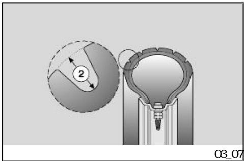
《2》 USA
After a thorough analysis aprilia has approved only the tyres listed below for this model:
Characteristic
Front tyre
110/70 16' 56S
150/70 14' 66S
110/70-16' 56S tubeless
rear tyre
150/70-14' 66S tubeless
(03_08, 03_09, 03_10, 03_11)
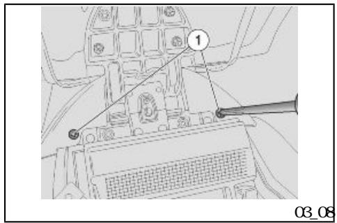
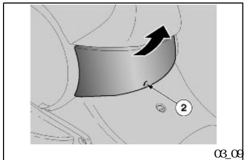
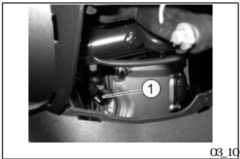
Spark plug disnantlenent (03_08, 03_09, 03_10, 03_11)
Check the spark plug according to the indications in the scheduled maintenance table.
Remove the spark plug regularly, clean off carbon scales, and replace it if necessary.

-
Lift the saddle.
-
Remove the battery cover and unscrewthe two fixing screws "2" on the central inspection cover.
-
Lower the saddle.
-
Unscrew and remove the bot tomcentral fixing screws "2".
-
Slide off the central in section cover.
For renewal and cleaning

《1》
CAUTION

BEFORE CARRYING OUT THE FOLLOWING OPERATIONS AND IN ORDER TO AVOID BURNS, LEAVE ENGINE AND MEFFLER TO COOL OFF TO AMOUNT TEMPERATURE
- Disconnect the cap "1" of the high voltage cable from the spark plug
Clean off any trace of dirt fromthe spark plug base. Unscrewit using the spanner supplied in the tool kit and remove it fromits place, being careful not to let dust or any other substance into the cylinder. - Check that the spark plug electrode and centre porcelain are free of carbon deposits or signs of corrosion. If necessary, clean using suitable spark plug cleaners, a wire and/or metal brush
- Blow with a strong air blast to avoid renewed dirt getting into the engine. Replace the spark plug if there are cracks on the spark plug insulating material, corroded electrodes or large deposits.
•
•

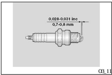
0.7-0.8mm
12-14Nm 1.2-1.4kg
- Check electrode gap with a thickness gauge and adjust if necessary by carefully bending the earth electrode.
- Make sure the washer is in good conditions. Once the washer is fitted manually, screw the spark plug to avoid damaging the thread
- Tighten using the spanner supplied in the tool kit, make the spark plug complete 1/2 a turn to press the washer.
- Insert the spark plug tube correctly so that it does not detach with engine vibrations.
- Refit the right inspection cover.
CAUTION

TIGHTEN THE SPARK PLUG CORRECTLY, OTHERWISE THE ENGINE MAY OVERHEAT AND GET IRREIRIEVABLE DAMAGED USE ONLY THE RECOMMENDED TYPE OF SPARK PLUG, OTHERWISE, THE ENGINE DURATION AND PERFORMANCE COULD BE COMPROSMED
Characteristic
Spark plug electrode gap
0.7-0.8mm
(03_12, 03_13)

•
9 《3》
4 《5
《5》
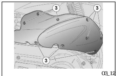
Renovngtheairfilter (03_12,03_13)
For replacing and cleaning the air filter see the scheduled maintenance table. If the vehicle is used on dusty or wet roads, clean or replace the filter more frequently.
-
Remove the filtering element from the scooter for cleaning
-
Place the scooter on its central stand
- Unscrew and remove the nine screws "3".
- Remove the filter housing cover "4" together with the filtering element "5".
- Check the filtering element "5" and replace it if necessary.
Air filter cleaning
Clean the filtering element "5" with a blast of presurised air.
| CAUTION | |
| TO AVOID RISK OF FIRE OR EXPLOSION DO NOT USE PEIROL OR FLammable solvents TO CLEAN THE FILTERING ELEMENT. | |
| DON'T USE ADDITIVES OR LIQUIDS WHEN CLEANING TO AVOID HUMIDITY INSIDE THE FILTER HOUSING USE COMpressed AIR ONLY. | |
| CAUTION | |
| DO NOT OL THE FILTERING ELEMENT OR OIL MAY GET INTO THE BELT HOUSING AND DAMAGE OR MAKE IT SLIDE | |
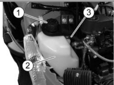
| (03_14) | Cooling fluid level (03_14, 03_15) |
| 50 | 50 Check the coolant level; according to the indications in the scheduled maintenance table. |
| Coolant liquid solution is 50% water and 50% antifreeze. This mixture is ideal for most operating temperatures and provide a good protection against corrosion. It is advisable to use the same mixture even in hot | |
weather as this minimises loss due to evaporation and the need of frequent top-ups. Thus, mineral salt deposits formed in the radiator by evaporated water are also minimised and the efficiency of the cooling system is not affected. When the temperature drops below zero degrees centigrade, check the cooling system frequently and add more antifreeze if needed (up to 60% max.).
Use distilled water in the coolant mixture to avoid damaging the engine.
.
CAUTION

DON'T USE YOUR VEHICLE IF THE COOL ANT LEVEL IS BELOW: MINIMUM LEVEL MARKED "MIN".
CAUTION

COCLANT IS TOCIF INGESTED, CON TACT WTHYOUR EYES OR SKIN MAY CAUSE IRRTATION IF THE FLUID GETS IN CONTACT WITH THE EYES OR SKIN RINSE REPEATEDLY WITH PLENTY OF WAIER AND SEEK MEDICAL ADVICE IF SWALLOWED. INDUCE VOTING RINSE MOIH AND THROAT WITH PLENTY OF WAIER AND SEEK MEDICAL ADVICE IMMEDIATELY
CAUTION

《1》

DO NOT REMOVE THE EXPANSION TANK PLUG «1» WHEN THE ENGINE IS HOT, SINCE COOLANT IS UNDER PRESSURE AND VERY HOT. CONTACT WITH SKIN OR CLOTHES MAY CAUSE SEVERE BURNS AND/OR INJURIES.
03_14
03_15
.
"1"
•
•
"1"
CHECKING
CAUTION


WIT FOR THE ENGINE TO COOL DOWNBEFORE CHECKING OR TOPPING UP THECOOLANT LEVEL.
- Shut off the engine and wait until it cools off.
- Remove the front case.
Loosen (turning it clockwise) but do not remove the filling cap "1". - Wait for some seconds so that possible pressure may be purged
Loosen and remove the cap "1".
"2" "MIX
MN=
MAX =
"MAX
《1》
《3》
《3》

- Check that the coolant level in the expansion tank "2" is up to the "MAX" mark.
MN = niri numl level.
MAX = maxnuml evel.
- If the coolant is not up to the "MAX" mark, top up the coolant.
NOE
PARK THE SCOOTER ON SAFE AND LEVEL GROUND
NOE
CAP "1" IS CONNECTED TO A BREATHER PIPE "3". DO NO FORCE OR DISCONNECT THE BREATHER PIPE "3".
CAUTION

COCLANT IS TOCIF INGESTED CON TACT WIHEYES OR SKINMAY CASE IR RITATION DO NOT INTRODUY YOR FINGERS OR ANY OTHER OBJECT TO CHECK IF THERE IS COCLANT OR NOT.
"MAX
1
TOPPING UP
- Top up with coolant until the fluid level is near the "MAX" level.
- Refit the filling cap "1".
- Refit the front case.
| CAUTION | |
| DO NOT ADD ADJITIVES OR OTHER SUB STANCES TO THE FLUID WHEN USING A FUNNEL OR ANY OTHER ELEMENT, MAKE SURE IT IS PERFECTILY CLEAN | |
| CAUTION | |
| IF THERE IS AN EXCESSIVE CONSUMPTION OF COOLANT OR WHEN THE EXPANSION TANK REMAINS EMPTY, CHECK THAT THERE ARE NO LEARS IN THE CIRCUIT. FOR RE PAIRS, TAKE YOUR VEHICLE TO AN OF FICIAL APRILIA DEALER | |
| aprilia | CAUTION |
| «MAX» | WEN TOPPING UP, DO NOT EXCEED THE «MAX» LEVEL OR THE FLUID WILL FLOW OUT WHEN THE ENGINE IS RUNNING |
| Recommended products | |
| SPECIAL AGIP PERMANENT fluid | |
| AGIP PERMANENT SPEZIAL | Coolant |
| " | Biodegradable coolant, ready for use, with "long life" technology and characteristics (pink). Freezing protection up to -40°. According to CUNA 956-16 standard |
| -40°C | CNA |
(03_16 03_17)
Checking the brake oil level (03_16, 03_17)
NE
THIS VEHICLE IS FITTED WITH FRONT AND REAR DISC BRAKES WITH INDEPENDENT HYDRALIC CIRCUITS. THE FOLLOWING INFORMATION REFERS TO ONE BRAKING CIRCUIT BUT IT APPLIES TO BOTH
CAUTION

aprilia

UNEXPECTED CLEARANCE VARIATIONS OR ELASTIC RESISTANCE IN THE BRAKE LEVER ARE DUE TO FAILURE IN THE HYDRALIC CIRCUIT. CONTACT AN Official aprilia Dealer IN CASE OF DOUBIS ON THE CORRECT OPERATION OF THE BRAKING SYSTEM OR WHEN UNABLE TO CARRY OUT ROUTINE CHECK PROCEDURES.
CAUTION
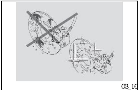
PAY SPECIAL ATTENTION TO THE BRAKE DISC AND THE FRICTION GASKES AND CHECK THAT THEY ARE NOT OLY OR GREASY, SPECIALLY AFTER MINENANCE OPERATIONS OR CHECKS. CHECK THAT THE BRAKE PIPE IS NOT TWISTED OR WORN
KEEP OUT OF THE REACH OF CHILDREN
DO NOT DISPOSE OF THE FLUID INTO THE ENVIRONMENT.
CAUTION
BRAKES ARE THE MOST IMPORTANT COMPONENTS TO ENSURE SAFETY AND THEREFORE THEY HAVE TO BE ALWAYS IN PERFECT CONDITIONS; CHECK THEMBEFORE EVERY RULE
A DIRY DISC SMEARS THE PADS RE SULTING IN POOR BRAKING REPLACE DIRY PADS AND CLEAN THE DIRY DISC USING A TOP-QUALITY DEGREASING PRODUCT.
03_17

Wien the friction pads wear out, the brake fluid level in the reservoir goes down to automatically compensate for that wear.
The brake fluid reservoir is located below the handlebar cover next to the brake lever attachments.
Check frequently the brake fluid level in the reservoirs and the brake pad wear.
CAUTION

DO NOT USE YOUR VEHICLE IF A FLUID LEAK IN THE BRAKING CIRCUIT IS DETECTED
.
•
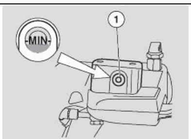
《1》 《MN》
•
《1》 MIN
MN =


"MN
CHECK
To check level:
- Rest the scooter on its centre stand
- Turn the handlebar so that the fluid in the brake fluid reservoir is parallel to the "MN" reference mark on the sight glass "1".
- Check that the level in the reservoir is over the reference "MN" indicated on the sight glass "1".
MN = Mri numl level.
CAUTION

PARK THE VEHICLE ON SAFE AND LEVEL GROUND
CAUTION

DON'T USE YOUR VEHICLE IF THE FLUID DOES NOT REACH AT LEAST AT THE «MIN» REFERENCE MARK
If the level is too low
- Check brake pads and disc for wear.
| Aprilia | If pads and/or the disc need not to be replaced Take your scooter to an Of ficial aprilia Dealer to carry out the replacement. |
| Aprilia | CAUTION BRAKE LEVEL DECREASES GRADUALLY AS BRAKE PADS WEAR DOWN |
| CAUTION CHECK BRAKING EFFICIENCY IN CASE OF EXCESSIVE TRAVEL OF THE BRAKE LEVER OR POOR PERFORMANCE OF THE BRAKING CIRCUIT, TAKE YOUR VEHICLE TO AN OFFICIAL APRILIA DEALER AS IT MAY BE NECESSARY TO PURGE AIR IN THE CIRCUIT. | |
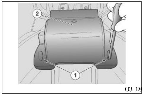
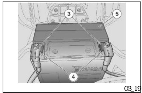
| 03_20 | (B03_18, 03_19, Battery (03_18, 03_19, 03_20) Check electrolyte level and terminal tightness according to the indications in the scheduled maintenance table. |
| CAUTION FIRE HAZARD FUEL OR ANY OTHER FLammable SUBSTANCES MUST NOT BE CLOSE TO ELECTRICAL COMPONENTS. THE BATTERY ELECTRICITY IS TOXIC CORROSIVE AND AS IT CONTAINS SUL PHRIC ACID IT CAN CAUSE BURNS WITH IN CONTACT WITH THE SKIN WEAR PRO |
15
TECIION CLOIHES, A FACE MSK AND/OR SAFETY COOGLS WHEN CARRYING OUT MINIENANCE OPERATIONS. IF THE ELECTRIC FLUID GETS INTO CONTACT WITH THE SKIN WISH WITH ABUNDANT COOL WATER
IF THE FLUID GEIS INTO CONTACT WITH THE EYES, WASH WITH ABUNDANT WATER FOR FIFTEEN MINUTES AND CONSULT AN EYE SPECIALIST IMMEDIATELY.
IF IT IS ACCIDENTALLY SWALLOWED, DRINK A LOT OF WATER OR MILK THEN MILK OF MAGNESIA OR VEGETAL QIL AND SEEK MEDICAL ADVICE IMMEDIATELY.
THE BATTERY RELEASES EXPLOVISE GASES. KEEP IT AWY OF FLAMES, SPARKS, CIGARETIES OR ANY OTHER HEAT SOURCE
WEN RECHARGING OR USING THE BATTERY, BE CAREFUL TO HAVE THE ROOM ADEQUATELY Aired DO NOT BREATH CASES RELEASED WHEN THE BATTERY IS BEING RECHARGED
KEEP OUT OF THE REACH OF CHILDREN
PAY ATTENTION NOT TO TILT THE VEH CLE EXCESSIVELY TO AVOID DANGEROUS SHILLS OF BATTERY FLUID
CAUTION
DO NOT INSERT THE CONEXIONS OF THE BATTERY LEADS.
《FF》
+
CONNECT AND DISCONNECT THE BATTERY WITH THE IGNITION SWITCH SET TO «OFF» OR THIS MAY DAMAGE SOME COMPONTS. CONNECT THE POSITIVE LEAD (+) FIRST AND THEN THE NEGATIVE ONE (-). DISCONNECT IN THE REVERSE OR DER
BATTERY FLUID IS CORROSIVE
DO NOT PUR OR SPREAD IT ESPECIALLY ON PLASTIC PARIS.
WEN RECHARGING A "MINIENANCE FREE BATTERY INSTALLED USE A SPECIFIC BATTERY CHARGER (VOLTAGE/CONSTANT AMPERAGE OR CONSTANT VOLTAGE TYPE).
USING A CONVENTIONAL BATTERY CHARGEMY DAMAGE THE BATTERY.
.
《FF》
•
2
《1》
•
《2》

BATTERY COVER REMOVAL
- Make sure the ignition switch is set to "OFF"
- Lift the saddle.
- Unscrew and remove the two screws "1".
- Slide off the battery cover "2"
CAUTION

PARK THE VEHICLE ON SAFE AND LEVEL GROUND
| · | ||
| · | ||
| · | «OFF» | |
| · | ||
| · | «3» | «4» |
| · | ||
| · | - | |
| · | + | |
| · | ||
| · | + | |
| · | - |
CHECKING AND CLEANING LEADS AND TERMINALS
- Remove the battery cover.
- Make sure the ignition switch is set to "OFF".
- Check that the leads "3" of the cables and the terminals "4" of the battery are:
in good conditions (not corroded or covered by deposits);
covered by neutral grease or petroleum leumjelly.
If necessary:
- Disconnect first the negative lead (-) and then the positive one (+) .
Brush with a metal bristle brush to remove all signs of corrosion - Connect again first the positive lead (+) and then the negative one (-).
Cover the leads and terminals with neutral grease or petroleum jelly.
•
.
.
•


.
.
1/10
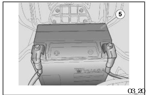
BATTERY RENOVAL
- Remove the battery cover.
- Disconnect first the negative lead (-) and then the positive one (+).
- Remove the battery "5" from its housing and place it on a level surface, in a cool and dry place.
- Refit the battery cover.
CAUION

ONCE REMOVED THE BATTERY MIST BE PUT AWY IN A SAFE PLACE OUT OF THE REACH OF CHILDREN
CAUTION

HANDLE WITH CARE AND MAXIMMATION AS ELECTRIGYE FLUID MAY SPILL OUT SINCE THE BATTERY IS NOT ENPIY
BATTERY RECHARGE
- Remove the battery.
- Connect the battery to a battery charger.
- A recharge with an amperage of 1/10 of the battery capacity is recommended.
5-10
Once the battery is re charged, control the electrolyte level and top up with distilled water if necessary.
- Refit the caps to the elements.
NOE
REFIT THE BATTERY ONLY 5-10 MINUTES AFTER DISCONNECTING THE CHARGER AS THE BATTERY KEeps PRODUCING CASES FOR A SHORT TIME
Use of a new battery
•
.

《5》
+
- Remove the battery cover.
- Place the battery "5" in its housing
- Connect first the positive lead (+) and then the negative one (-).
Cover the leads and terminals with neutral grease or petroleum jelly. - Refit the battery cover.
CAUTION

ALWAS CONNECT THE BATTERY BREATHER SO THAT SULPHORIC ACID STEAM FROM THE BREATHER DOES NOT CORDE THE ELECTRICAL SYSTEM PAINIED PARIS, RUBBER COMPONENTS OR GASKETS.
Long periods of inactivity
If the scooter has been inactive for a long time, starting may be delayed as the fuel supply circuit may be partially empty.
15
PROLINED INACTIVITY OF THE BATTERY
If the scooter is inactive longer than fifteen days, it is necessary to recharge the battery to avoid sulphation.
- Remove the battery and put it away in a cool and dry place.
1
In winter or when the vehicle remains stopped, check the charge frequently (about once a month) to avoid deterioration.
Fully recharge with an ordinary charge.
If the battery is still on the vehicle, disconnect the cables from the terminals.
(03_21, 03_22, 03_23)
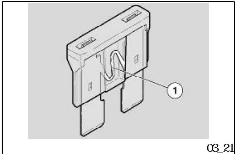
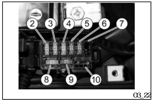
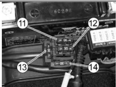
Fuses (03_21, 03_22, 03_23)
CAUTION


NEVER ATTEMPT TO REPAIR FALTY FUSES. NEVER USE A FUSE OF A RATING OTHER THAN SPECIFIED THIS COULD DAMAGE THE ELECTRICAL SYSTEM OR CAUSE A SHORT CIRCUIT, WITH THE RISK OF FIRE
CAUTION


A FUSE THAT BLOW FREQUENLY MAY INDICATE A SHORT CIRCUIT OR OVER LOAD IF THIS OCCURS, CONTACT AN Official aprilia Dealer.
aprilia
Checking the fuses is necessary whenever an electrical component fails to operate or is malfunctioning or when the engine does not start.
10A 15A
30A
First check the 10 A and 15 A fuses, and then the 30 A fuses.
:
"1"
To carry out the check
- Remove the battery cover.
- Extract one fuse at a time and check if the filament "1" is broken.
•
•
Before replacing the fuse, find and solve, if possible, the problem that caused the problem
If the fuse is damaged, replace it with one of the same anperage.
- Refit the battery cover.
NEE
IF THE SPARE FUSE IS USED REPLACE
WH ONE OF THE SAME TYPE IN THE
CORRESPONDING FITTING
AUXILIARY FUSES DISTRIBUTION
| 2 15A | |||
| A | |||
| 3 15A | B | ||
| 4 15A | C | ||
| 5 10A | ECU | ||
| (2) 15A fuse | Fromthe voltage regulator to Fan relay, injection stop/ ignition light logic (seat A on the electrical diagram). |
| (3) 15A Fuse | Fromthe ignition switch to Plug socket (seat B on the electrical diagram). |
| (4) 15A Fuse | From the ignition switch to lights, horn, instrument panel, radio (seat C on the electrical diagram). |
| (5) 10A fuse | Frommain fuse to ECU alarm electric lock, glove compartment light |
| 6 10A | ECU |
| 7 | |
| 8 15A | |
| 9 10A | |
| 10 |
| (6) 10A fuse | Fromthe voltage regulator to Continuous power supply, ECU fan |
| (7) | Free |
| (8) 15A fuse | Spare Parts |
| (9) 10A fuse | Spare Parts |
| (10) | Free |
ARRANGEMENT OF MIN FUSES
| 11 30A |
| 12 30A |
| 13 30A |
| 14 30A |
| (11) 30A fuse | Fromthe battery to General power supply, plug socket |
| (12) 30A Fuse | Fromthe battery to Alternator, battery regulator, plug socket. |
| (13) 30A fuse | Spare Parts |
| (14) 30A fuse | Spare Parts |
03_23

Lamps
CAUTION

FIRE HAZARD FUEL OR ANY OTHER FLAMMABLE SUBSTANCES MUST NOT BE CLOSE TO ELECTRICAL COMPONENTS.
CAUTION

"KEY CFF"

BEFORE REPLACING A BUB, TURN THE IGNITION SWITCH TO "KEY OFF" AND WAIT A FEWMINUTES FOR THE BUB TO COOL OFF.
Wear CLEAN GLOVES OR USE A CLEAN DRY CLOTH TO REPLACE THE BUB
DO NOT LEAVE PRINTS ON THE BLB AS THIS MAY CAUSE IT TO OVERHEAT OR EVEN
| 12V - 55W 12V - 55W | |
| 12V - 5W | |
| 12V - 10W | 12V - 10W |
| 12V - 5W21W | |
| 12V - 5W | |
| LED | |
| LED | |
| LED | |
| LED | |
BULBS/ WRRING LIGHTS
| High /low beambulb | 12V - 55W/ 12V - 55W |
| Front parking light bulb | 12V - 5W |
| Rear/front turn indicator bulb | 12V - 10W(rear) / 12V - 10W(front) |
| Rear tail light /stop lightbulb | 12V - 5W21W |
| License plate light bulb | 12V - 5W |
| Instrument panel lighting bulb | LED |
| Turn indicator warning light | LED |
| Engine oil pressure warninglight | LED |
| Low beam warning light | LED |
| High beam warning light | LED |
| Low fuel warning light | LED |
(03_24, 03_25, 03_26)
《1》1
2 1
3 1
《4》
2
2
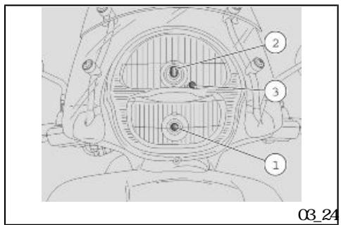
Front light group (03_24, 03_25, 03_26)
In the front headlight there are:
One high-beamlight bulb "1".
One low beam light bulb "2".
One tail light bulb "3".
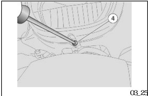
To replace low/high beam light bulbs:
- Unscrew and remove the lower screw"4".
- Remove the front headlight ring nut.
- Remove the headlight upper lock.
- Unscrew and remove the two headlight fixing screws.
Take the headlight off the two lower bolts. - Disconnect the connector and remove the headlight.
•
•
2
2
- Slide off the rubber protection
Turn the bulb holder clockwise and take it out of the parabol e seat. - Extract the bulb.
When refitting
- Place the bulb holder in its paraboloe seat and turn it clockwise.
- Connect the bulb electrical connector.
CAUION
DO NOT PULL THE ELECTRICAL CABLES
WEN TAKING OUT THE BULB ELECTRICAL CONNECTOR
NOE
INSERT THE BUB IN THE PARABOLE SEAT SO THAT THE TWO NOTCHS ON THE BUB CONCIDE WITH THEIR GUIDES ON THE BUB HOLDER
•
•
- Connect the headlight connector.
- Refit the headlight
NOE
WEN REFITIING THE PROIECION CAP BE CAREFUL TO PRESS ALL AONG THE PERIMETER CORRESPONDING TO THE MARK "PUSH TO ENSURE WATER TIGHTNESS, AND THEN CLOSE THE TABS.
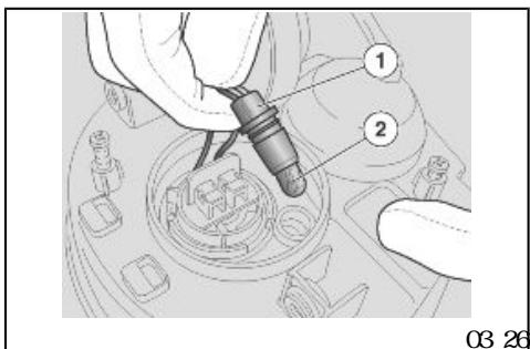
《1》
《2》

To replace the tail light bulb
Fromthe headlight bottom side, hold and pull the bulb holder "1" to extract it from its seat.
- Slide off the headlight bulb "2" and replace it with an other of the same type.
CAUTION

DO NOT PULL THE ELECTRICAL CABLES
WENTAKING OUT THE BUB HOLDER
03_28
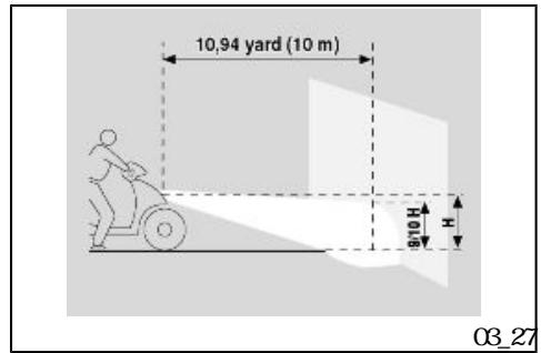
(03_27,
10 m
Headlight adjustment (03_27, 03_28)
For a quick check of the correct direction of the front light beans, place the scooter ten metres from a vertical wall and make sure the ground is level.
9/10
《1》
Turn on the low beamlight, sit on the scooter and check that the light beamprjected to the wall is a little below the headlight horizontal straight line (about 9/10 of the total height).
To adjust the light beam
- Unscrew and remove the headlight lower screw"1".
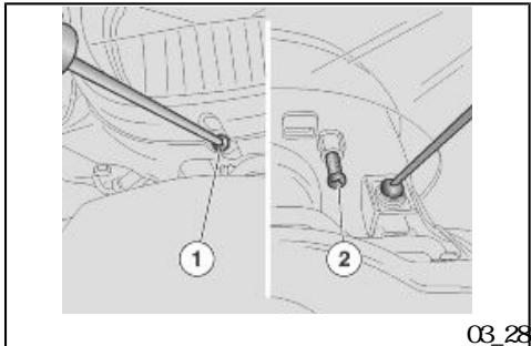
(03_29,03_30,03_31,03_32)
- Remove the chroniumplated ring nut.
- Move the headlight upper lock slightly forward but do not remove it.
- Insert a screwdriver in the front headlight set screw "2". Turn it CLOCKWISE to lower the light beam. Turn it ANTI-CLOCKWISE to lift the light beam
(03_29, 03_30, 03_31, 03_32)
Front direction indicators (03_29, 03_30, 03_31, 03_32)
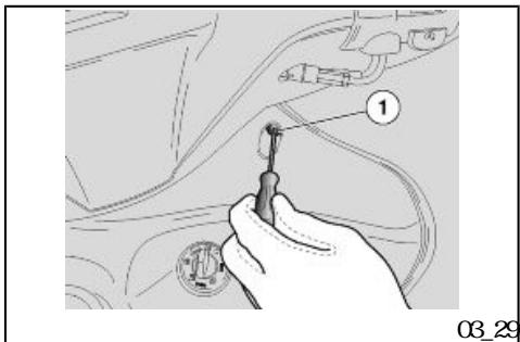
1 《1》
To replace the bulbs remove the front case as follows:
- Rest the vehicle on its centre stand
- Turn the handlebar fully to the right and remove the screw "1".
Repeat the same procedure on the opposite side, turning the handlebar fully to the left.
《2》
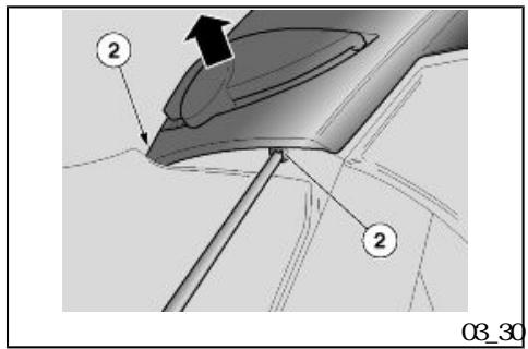
•
•

Turn the handlebar fully to the right and remove the screw"2".
- Repeat the same procedure on the opposite side, turning the handlebar fully to the left.
- Lift the case slightly as shown by the arrow and detach from the fittings.
CAUTION

PROCEED WITH CAUTION
DO NOT DAMAGE THE TABS AND/OR THEIR CORRESPONDING SLOTS.
HANILE PLASTIC AND PAINTED COMPO NENIS WITH CARE,DO NOT SCATCH OR SPOL THEM
CAUTION
WEN REFTIING INSERT TAES IN THEIR SLOTS WITH THE CORRESPONDING CLIPS.
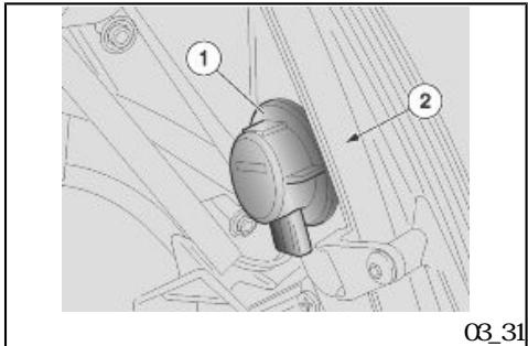
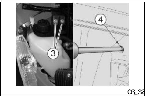
"1"
"2"
2 3
"4"
.
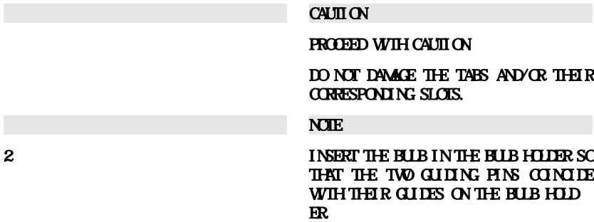
On the left side:
- Turn the bul b holder "1" clockwise.
Turn the bulb "2" anticlockwise.
On the right side:
- Unscrew and remove the two upper screws "3" of the expansion tank
- Open the glovebox.
- Unscrew the lower screw "4" of the expansion tank through the hole in the glovebox.
- Lift the expansion tank to reach the right bulb.
- Follow the sane procedure as for left bulb.
Installabulbofthesametypeadequately.
Reinstall in the reverse order.
CAUTION
PROCEED WITH CAUTION
DO NOT DAMAGE THE TABS AND/OR THEIR CORRESPONDING SLOTS.
NEE
INSERT THE BUB IN THE BUB HOLDER SO THAT THE TWO GIDING PINS CINIDE WITH THEIR GUIDES ON THE BUB HOLDER
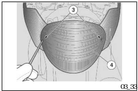
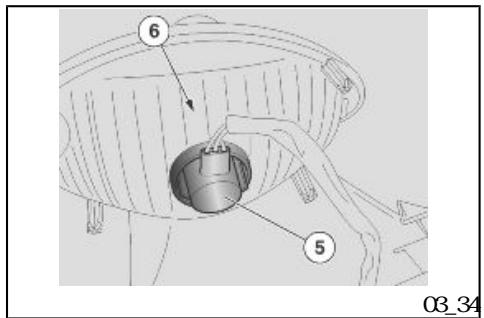
03_34
2 《3》
《4》
《5》
《6》
(03_33 Rear optical unit (03_33 03_34)
To replace the bulbs:
- Unscrew and remove the two screws "3".
-
Slide off the rear headlight "4".
-
Slide off the bulb holder "5" and extract the rear headlight.
Turn the bulb "6" anticlockwise. - Remove and replace the headlight.
CAUTION
PROCEED WITH CAUTION
DO NOT DAMAGE THE TABS AND/OR THEIR CORRESPONDING SLOTS.
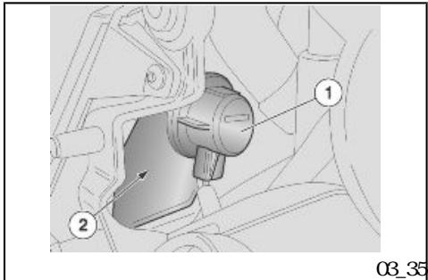
(03_35)
•
•
•
《1》
《2》
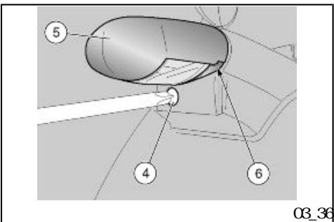
03_37
•
•
•
《4》
》
《6》
Rear turn indicators (03_35)
To replace the bulbs:
- Remove the rear headlight.
Turn the bulb holder "1" clockwise and extract it.
Turn the bulb "2" anticlockwise and slide it off the bulb holder.
(03_36) Number plate light (03_36, 03_37)
To replace the bulb
- Unscrew and remove the screw "4".
- Remove the license plate bulb support "5".
- Slide off the bulb "6" and replace it with another of the same type.
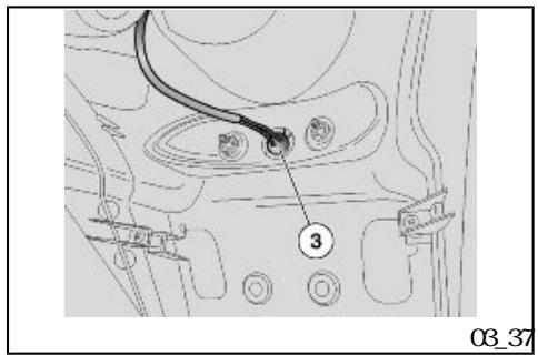


To replace the bulb
- Held and pull the bulb holder "3" to extract it from its seat.
- Slide off and replace the bulb with another of the same type.
CAUTION

DO NOT PULL THE ELECTRICAL CABLES
WENTAKING OUT THE BUB HOLDER
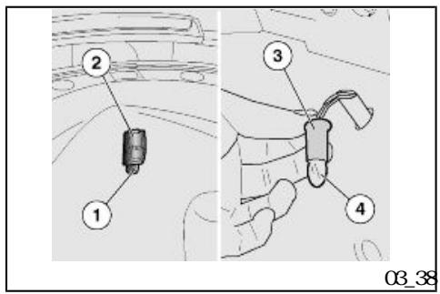
(03_38)
•
•
•
《2》
《4》

Helmet compartment lighting bulb (03_38)
For replacement:
- Lift the saddle.
Loosen and remove the fixing screw"1" on the battery cover glass. - Remove the glass "2" and slide it off downward
- Hld and pull the bulb holder "3" to extract it from its seat.
- Slide off the bulb "4" and replace it with another of the same type.
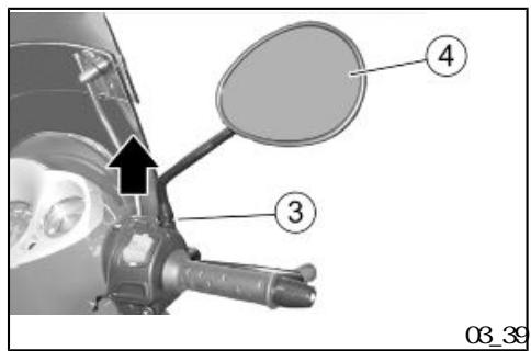

(03_39)
"3"
"4"
"3"
CAUTION

DO NOT PULL THE ELECTRICAL CABLES
WENTAKING OUT THE BUB HOLDER
Rear-view mirrors (03_39)
The following information refers to one rear view mirror but is valid for both
- Rest the scooter on its centre stand
- Unscrewthe tap "3".
- Remove the rear-view mirror "4" and slide it off upward
Take care not to lose the cover "3" and the spacer.
NEE
ASSEMBLE THE COMPONENTS FOR THE RIGHT AND THE LEFT REAR - VIEWMIR RORS SEPARATELY.
CAUTION

"4"

HOLD THE REAR VIEW MIRROR "4" TO AVOID DROPPING IT BY ACCIDENT.
CAUTION


HANLE THE PLASTIC AND PAINTIED COMPONENTS WITH CARE, DO NOT SCRAITCH OR SPOL THEM
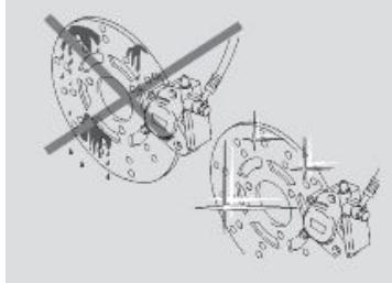
03-40
(03_40, 03_41, 03_42, 03_43)
Front and rear disc brake (03_40, 03_41, 03_42, 03_43)
NOE
THIS VEHICLE IS FITTED WITH FRONT AND REAR DIS C BRAKES WITHINDEPENDENT HORMALLC CIRCUITS. THE FOLLOWING INFORMATION REFERS TO ONE BRAKING CIRCUIT BUT IT APPLIES TO BOTH
CAUTION


aprilia
UNEXPECTED CLEARANCE VARIATIONS OR ELASTIC RESISTANCE IN THE BRAKE LEVER ARE DUE TO FAILURE IN THE HY DRAULIC CIRCUIT. CONTACT AN Official aprilia Dealer IN CASE OF DOLBIS ON THE CORRECT OPERATION OF THE BRAKING SYSTEM OR WHEN UNABLE TO CARRY OUT ROUTINE CHECK PROCEDURES.
CAUTION
PAY SPECIAL ATTENTION TO THE BRAKE DISC AND THE FRCION GASKES AND
CHECK THAT THEY ARE NOT CILY OR GREASY, SPECIALLY AFTER MINIENCE OPERATIONS OR CHECKS. CHECK THAT THE BRAKE PIPE IS NOT TWISTED OR WBN
KEEP OUT OF THE REACH OF CHILDREN
DONT DISPOSE OF THE FLUID INTO THE ENVIRONMENT.
CAUTION
BRAKES ARE THE MOST IMPORTANT COMPONENTS TO ENSURE SAFETY AND THEREFORE THEY HAVE TO BE ALWAYS IN PERFECT CONDITIONS; CHECK THEMBEFORE EVERY RULE
A DIRY DISC SMEARS THE PADS RE SULTING IN POOR BRAKING REPLACE DIRY PADS AND CLEAN THE DIRY DISC USING A TOP-QUALITY DEGREASING PRODUCT.
Pads wear check
Check brake pads for wear according to the indications in the Scheduled maintenance chart.
Disc brake pad wear depend on the use, the riding style and the roads.
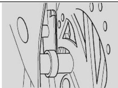
03_41
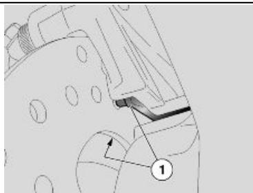
03_42

NOE
THE FOLLOWING INFORMATION REFERS TO ONE BRAKING CIRCUIT BUT IS VALID FOR BOTH
To carry out a quick pad check:
- Rest the vehicle on its centre stand
- Carry out a visual inspection of brake disc and pads as follows.
Front brake callipers
From the front bottomside for both callipers.
CAUTION


CHECK BRAKE PADS FOR WAR MINLY BEFORE EACH RIDE
《1》
Rear brake calliper
From the back bottom side for both pads "1".
NOE
EXCESSIVE YEAR OF THE FRICTION MA TERIAL MAKES THE PAD METAL SUPPORT GET INTO CONTACT WITH THE DISC WHICH RESULTS IN A METALLIC NISE AND SPARKS IN THE CALLER THERE
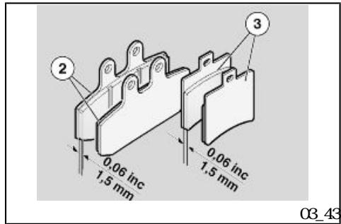
1.5mm
《2》
《3》
If the friction material thickness (even in only one pad) is reduced to about 1.5 mm replace both pads.
Front pads "2".
Rear pads "3".
aprilia
CAUTION
TAKE YOUR SCOTIER TO AN Official aprilia Dealer TO HAVE DISCS REPLACED
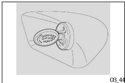
03_45)
(03_44
Periods of inactivity (03_44, 03_45)
Take some measures to avoid the side effects of not using the vehicle. Besides, it is necessary to carry out general repairs and checks before garaging the vehicle as one can forget to do so afterwards.
•
•
Proceed as follows:
Empty the fuel tank completely.
- Remove the spark plug.
Pour a teaspoonful (5-10 cm) of engine oil into the cylinder.
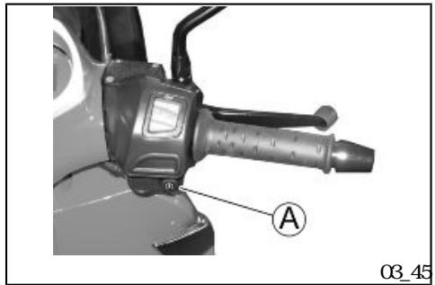
"ON A
.
.
.
.
.
.
.
.
.
Cover the use plasti materials. AFTER STORAGE
AFTER STORAGE
- Set the ignition switch to "ON" and press the starter button "A" for a few seconds to distribute the oil on the cylinder surfaces uniformly.
- Remove the protection cloth
- Refit the spark plug
- Remove the battery.
- Wash and dry the scooter.
Polish the painted surfaces.
Inflate tyres. - Place the scooter so that both tyres do not touch the ground using a specific support.
-
Store the vehicle in a cool, dry place, away from sunlight and with steady temperature.
Put a plastic bag on the muffler exhaust end and tie it so that humidity cannot get in
Cover the scooter but do not use plastic or waterproof materials. -
Uncover and clean the scooter.
- Check that the battery charge is OK and fit it.
- Refill the fuel tank.
- Carry out the preliminary checks.
CAUTION

AS A TEST, RIDE THE VEHICLE FOR A FEW KILONETIES AT A MODERATE SPEED AND AWAY FROM TRAFFIC AREAS.
Cleaning the vehicle
Clean the vehicle frequently when it is exposed to adverse conditions, such as:
Air pollution (cities and industrial areas)
Salinity and humidity in the atmosphere (seashore areas, hot and wet weather).
- Special ambient/seasonal conditions (use of salt, anti-icing chemical products on roads in winter).
- Make sure to clean off any industrial residue or polluting dirt as well as re


novetarstairs,deadin sects,bird droppings,etc.
- Avoid parking your vehicle under trees; During some seasons, resins, fruits or leaves containing aggressive chemical substances that may damage the paintwork may fall from trees.
CAUTION

AFTER CLEANING YOUR VEHICLE, BRAKING EFFICIENCY MAY BE TEMPORARILY AFFECIED DUE TO THE PRESENCE OF WAIER ON THE FRCION SURFACES OF THE BRAKING CIRCUIT. CALCULATE A LONGER BRAKING DISTANCE IN ORDER TO AVOID ACCIDENTS. BRAKE REPEATEDLY TO RESTORE NORMAL OPERATION CARRY OUT THE PRE-RIDE CHECKS.
To remove dirt and mud deposited on the painted surfaces, use a low pressure water blast to soak all 2 4 dirty parts carefully. Wipe off mud and dirt with a soft sponge for bodywork soaked in a lot of water and shampoo (2 ... 4 % parts of shampoo in water). Then rinse abundantly with water and dry with a shampy cloth. To clean the engine outer parts, use degreasing detergent, brushes and cloth
CAUTION
DO NOT APPLY ANY PROJECTIVE WAX ON THE SADDLE OR IT MAY BECOME SLIP PERY.
CAUTION


40° C
REMEBER TO CLEAN THE SCOOTER CARE FULLY BEFORE ANY POLISHING WITH SILICON WAX DO NOT POLISH MATT- PAINIED SURFACES WITH POLISHING PASTE THE SCOOTER SHOULD NEVER BE WASHED IN DIRECT SUNLIGHT, ESPE CALLY DURING SUMMER, WITH THE BODYWARK STILL HOT, AS THE SHAMPOD CAN DAMAGE THE PAINTWARK IF IT DRIES BEFORE BEING RINSED OFF. DO NOT USE LIQUIDS AT TEMPERATURES OVER 40 ° C WHEN CLEANING PLASTIC PARTS OF THE SCOOTER DON'T DIRECT HIGH PRESSURE WAIER OR AIR JEIS OR STEAM TO THE FOLLOWING PARTS: WEEL HBS, CON TROLS LOCATED ON THE RIGHT OR LEFT SIDE OF THE HANDLER, BEARINGS, BRAKE PUMPS, INSTRUMENTS AND GALGES, MFFLER EXHAUST, GLOW-BOX TOOL KIT, IGNITION SWITCH/STEERING DON'T USE ALCOHOL, PEIROL OR SOLVENTS TO CLEAN RUBBER AND PLASTIC PARTS. USE ONLY WAIER AND NEJIRAL SOAP INSTEAD DO NOT USE SOLVENTS OR PEIROL BY PROD UCIS (ACETONE, TRICHORO EITHMENE, TURPENINE, PEIROL, THNERS) TO CLEAN THE SADDLE USE INSTEAD DE TERGENTIS WITH SURFACE ACTIVE AGENIS
5%
- 2
3
NOT EXCEEDING 5 % (NEURAL SOAP, DE GREASING DETERGENS OR ALCOHOL). DRY THE SADDLE WILL AFTER CLEANING
NOE
SCOOTER CLEANING TIPS
- REMOVE ALL OBJECTS FROM INSIDE THE FRONT CASE AND THE HELNET COMPARINENT; REMOVE MOQETTE CARPET IN THE HELNET COMPARINENT;
- MAKE SURE ALL THE COMPARTMENTS ALL ADEQUATELY CLOSED
3 WASH ONLY WITH NEUTRAL DE TERCENT AND RINSE WITH WAIER BUT NOT WITH PRESSURE
Transport
CAUTION
BEFORE TRANSPORING THE VEHICLE, IT IS NECESSARY TO EMPTY THE FUEL TANK AND THE CARBURETOR ADEQUATELY, CHECKING THAT THEY ARE DRY.
VALE TRANSPORING THE VEHICLE, IT SHOULD BE AT ALL TIMES VERTICAL AND WILL ANCHRED IN ORDER TO AVOID FUEL, CIL OR COOLANT LEAKS.
IN CASE OF FAILURE, DO NOT HAVE THE VEHICLE TO BE ASK FOR AN ADEQUATE ASSISTANCE


FIREFHAZARD
WIT UNIL THE ENGINE AND THE MIF FLER ARE COLD
FUEL VAPOURS ARE HARMFUL TO HEALTH
BEFORE ANY OPERATION MAKE SURE THAT THE ROOMWHERE YOU ARE HAS ADEQUATE AIR VENTILATION
DO NOT IN-ALE FUEL VAPOLS.
DO NOT SMKE OR USE NAKED FLAMES.
DONT DISPOSE OF FUEL INTO THE ENVIRONMENT
- Rest the scooter on its centre stand and on safe and level ground
- Shut off the engine and wait until it cools off.
Take a container with a capacity higher than the amount of fuel in the tank and place it on the scooter left hand side. - Remove the fuel tank cap.
To drain the fuel off the tank use a hand-operated pump or a similar system
CAUTION
AFTER EMPTYING THE TANK REIT THE FUEL TANK CAP ADEQUATELY
SCARABEO 250 i.e.

04
Chap 04 Technical data
TECHCAL DATA
| 2263 mm | Max. length | 2263 mm | |
| 790 mm | Max. width | 790 mm | |
| 1419 mm | Max height (to windscreen) | 1419 mm | |
| 785 mm | Saddle height | 785 mm | |
| 1535 mm | Centre to centre distance | 1535 mm | |
| 215 mm | Mini numground clearance | 215 mm | |
| 194 kg | Kerb weight | 194 kg | |
| Variator transmission | continuous, automatic | ||
| V | Main transmission | V-belt | |
| Secondary transmission | Gear reduction unit | ||
| 1/14.083 | Engine/ wheel total ratio | short 1/14.083 | |
| 1/5.406 | long 1/5.406 | ||
| 13.2 l | Fuel (reserve included) | 13.2 l | |
| 3 l | Fuel reserve | 3 l | |
| 1100 cm³ | Engine oil (Engine oil change and engine oil filter replacement) | 1100 cm³ | |
| ~250 cm³ | Transmission on oil | ~250 cm³ | |
| 50% + 50% | Coolant (50% water + 50% ethylene glycol antifreeze fluid) | 1.7 l | |
| 2 | Seats | 2 | |
| + | 115 kg | Scooter max load (rider + luggage) | 115 kg |
| + | 190 kg | Scooter max load (rider + passenger + luggage) | 190 kg |
| Chassis type | high-resistant steel tubes | ||
| 27.5" | Steering inclination angle | 27.5" | |
| 108 mm | Trail | 108 mm | |
| 260 mm | Front brake | Ø 260 mm disc brake with hydraulic transmission | |
| - Ø 260 mm Ø 240 mm | Combined rear brake | Double disc - Ø 260 mm front disc and Ø 240 mm rear disc | |
| 16"x3 00 | Front wheel rim | 16 x 3 00' nade of light alloy | |
| 14"x3 5 | Rear wheel rim | 14"x3 5 light alloy rim | |
| Tyre type | Without inner tube (Tubeless) | ||
| 110/70 - 16' 52P | Front tyre: | 110 /70 - 16' 52P tubel ess | |
| 140/70 - 14' 68P | Rear tyre: | 140/70 - 14' 68P tubel ess | |
| 2.1 bar | Front tyre pressure (rider only) | 2.1 bar | |
| 2.1 bar | Rear tyre pressure (rider only) | 2.1 bar | |
| 2.1 bar | Front tyre pressure (passenger + rider) | 2.1 bar | |
| 2.2 bar | Rear tyre pressure (passenger + 2.2 bar rider) | 2.2 bar | |
ENGINE TECHNICAL DATA
| Front suspension | hydraulic telescopic fork | |
| 100 mm | Front suspension travel | 100 mm |
| Rear suspension | hydraulic action double-acting shock absorber, adjustable preloading | |
| 80 mm | Rear suspension travel | 80 mm |
| 12V - 14Ah | Battery | 12V-14Ah |
| 30, 15, 10A | Fuses | 20 - 15 - 10 A |
| 14V - 380W | (Permanent magnet) Generator | 14V - 380W |
| M2801 | |
| 4 | 4 |
| SOHC | |
| 4 | |
| 1 | |
| 244.29 cm3 | |
| 72 mm/60 mm | |
| 11.0 ± 0.5:1 | |
| 1600 ± 100 rpm | |
| Model | M80CM |
| Engine type | Single-cylinder, 4-stroke, 4 valves, wet sump forced lubrication system, overhead canshaft. |
| Valve quantity | 4 |
| Cylinder quantity | 1 |
| Overall engine capacity | 244.29 cm³ |
| Bore/stroke | 72 mm/60 mm |
| Compression ratio | 11.0 ± 0.5:1 |
| Start-up | Electric |
| Engine revs at idle speed | 1600 ± 100 rpm |
| Clutch | Automatic centrifugal dry clutch | |
| Gear | automatic | |
| Ø 32 mm | Cooling | forced circulation air cooling driven by a centrifugal pump |
| Throttle body diffuser | Ø 32 mm | |
| 95 NRM | SUPPLY | By electronic injection with electric fuel pump |
| 85 NOM | ||
| 4 Stars UK | ||
| CDI / | Fuel | Unleaded premiumpetrol (4 Stars UK) with minimunoctane rating of 95 (NRM) and 85 (NOM) |
| Ignition type | CDI / inductive | |
| CHAMION RGA PHP | Ignition advance | Variable advance controlled by the injection control unit |
| 0.7 - 0.8mm | ||
| Spark plug | CHAMION RGA PHP | |
| Spark plug electrode gap | 0.7 - 0.8 mm |
BULBS/ WRRNING LIGHTS
| 12V - 55W 12V - 55W | High /low beambul b | 12V - 55W/ 12V - 55W |
| Front parking light bulb | 12V - 5W | |
| Rear/front turn indicator bulb | 12V - 10W(rear) / 12V - 10W(front) | |
| 12V - 10W 12V - 10W | ||
| 12V - 5W21W | Rear tail light /stop light bulb | 12V - 5W21W |
| 12V - 5W | License plate light bulb | 12V - 5W |
| LED | Instrument panel lighting bulb | LED |
| LED | Turn indicator warning light | LED |
| LED | Engine oil pressure warning light | LED |
| LED | Low beam warning light | LED |
| LED | High beam warning light | LED |
| LED | Low fuel warning light | LED |
| LED | High coolant temperature gauge warning light | LED |
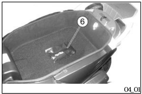
(04_01)
"6"
16 mm
Kit equipment (04_01)
The tool kit "6" is attached under the saddle.
To reach it:
Release and lift the saddle.
The tools supplied are:
- Pouch bag
- Twin screwdriver.
- Box spanner 16 mm
- Shock absorber wrench
-Allenkey4mm
SCARABEO 250 i.e.

05
Chap 05
Spare parts and
accessories
SCARABEO 250 i.e.

06
Chap 06
Programmed
naintenance

CAUTION

FIRE HAZARD
FUEL OR ANY OTHER INFLAMMBLE SUB STANCES MIST NOT BE CLOSE TO ELECTRICAL COMPONENTS.
BEFORE ANY MINENANCE OPERATION OR INSPECTION ON THE VEHICLE, SHT OFF THE ENGINE AND REMOVE THE KEY. WITH UNIL THE ENGINE AND THE EXHAUST SYSTEMARE COLD WHENEVER POSSIBLE, LIFT THE VEHICLE WITH A SPECIFIC EQUIPMENT ON A FIRM AND LEVEL GROUND
BEFORE ANY OPERATION MAKE SURE THAT THE ROOMWHERE YOU ARE HAS ADEQUATE AIR VENTILATION
TO AVOID BURNS BE SPECIALLY CAREFUL WITH HOT ENGINE AND EXHAUST SYSTEM PARIS.
DO NOT HOLD ANY MECHANICAL OR OTHER VEHICLE PARTS WITH YOUR MUIH VE HOLE COMPONENTS ARE NOT EPILE; ON THE CONTRARY, SOME OF THEM ARE HARMFUL AND EVEN TOXIC
NOE
UNLESS OTHERWISE INDICATED REFIT THE UNIT FOLLOWING THE REMOVAL STEPS BUT IN REVERSE ORDER
WEN CARRYING OUT MINIENANCE OPERATIONS, IT IS ADMISABLE TO WEAR LA TEX GLOVES.
aprilia
aprilia
In general terms, routine maintenance operations can be carried out by the owner; however, some operations may require specific tools and technical training.
For servicing or technical advice, consult an Official aprilia Dealer for prompt and accurate service.
Ask your Official aprilia Dealer to test the vehicle on the road after a repair but nonetheless, personally carry out the Pre-ride Checks after a maintenance operation
PEROCIC MINENANCE CHART
Adequate maintenance is fundamental to ensuring long-lasting optimum operation and performance of your vehicle.
For this purpose, aprilia offers a set of checks and maintenance services (at the owner's expense), which are included in the summary table
aprilia
aprilia
shown on the following page. Any minor faults should be reported without delay to any official aprilia Dealer without waiting until the next scheduled service to solve it.
Carrying out scheduled services on time is essential for your warranty validity. For further information concerning Warranty procedures and Scheduled Maintenance, please refer to the Warranty Booklet.
2
EVERY 2 YEARS
Coolant - Check
Brake fluid - change
1,000KM
- CCO KM
Safety locks - check
Throttle lever - adjustment
Q1 filter - Replacement
Electrical system and battery - Check
Coolant level - check
Brake fluid level - check
Engine oil - Change
| - | Brake pad wear - check |
| - | Tyre pressure and wear - check |
| - | Vehi c e and brake test - test drive |
| - | Hib oil - Change |
| - | Steering - check up |
| 5,000 KM | 25,000 KM | 35,000 KM | 55,000 | 5,000 KM- | 25,000 KM- | 35,000 KM- | 55,000 KM- | 65,000 KM |
| KM | 65,000 KM | KM |
| - | Engine oil - level check/topping-up |
| - | Brake pad wear - check |
| 10,000 KM 50,000 KM 70,000 KM | 10,000 KM - 50,000 KM - 70,000 KM |
| - | Safety locks - check |
| - | Throttle lever - adjustment |
| - | Air filter - cleaning |
| - | Air filter in belt compartment - Check |
| - | Engine oil filter - Replace |
| - | Electrical systemand battery - Check |
| - | Coolant level - check |
| - | Brake fluid level - check |
| - | Engine oil - Change |
| - | Brake pad wear - check |
| - | Tyre pressure and wear - check |
| - | Vehicle and brake test - test drive |
| - | Hub oil - Check |
| - | Suspensions - Check |
| - | Steering - check up |
| - | Sliding block/ variable speed rollers - Replacement |
15,000KM 45,000KM 75,000KM
15.000KM-45.000KM-75.000KM
Engine oil - level check/topping up
Brake pad wear - check
20,000KM 40,000KM 80,000KM
20,000KM-40,000KM-80,000KM
Spark plug - Replace
Driving belt - replacement
Throttle lever - adjustment
Air filter - cleaning
Air filter in belt compartment - Check
Engine oil filter - Replace
| - | Valve clearance - check |
| - | Electrical systemand battery - Check |
| - | Coolant level - check |
| - | Brake fluid level - check |
| - | Engine oil - Change |
| - | Brake pad wear - check |
| - | Sliding block/ variable speed rollers - Replacement |
| - | Tyre pressure and wear - check |
| - | Vehicle and brake test - test drive |
| - | Hub oil - Change |
| - | Suspensions - Check |
| - | Steering - check up |
30.000 KM
30.000 KM
Safety locks - check
Throttle lever - adjustment
Air filter - cleaning
Air filter in belt compartment - Check
Engine oil filter - Replace
Electrical system and battery - Check
Coolant level - check
| - | Brake fluid level - check |
| - | Engine oil - Change |
| - | Brake pad wear - check |
| - | Sliding block/ variable speed rollers - Replacement |
| - | Tyre pressure and wear - check |
| - | Vehicle and brake test - test drive |
| - | Hub oil - Check |
| - | Suspensions - Check |
| - | Steering - check up |
60.000 KM
60.000 KM
Spark plug - Replace
Driving belt - replacement
Throttle lever - adjustment
Air filter - cleaning
Air filter in belt compartment - Check
Engine oil filter - Replace
Valve clearance - check
Electrical system and battery - Check
Coolant level - check
Brake fluid level - check
| - | Engine oil - Change |
| - | Brake pad wear - check |
| - | Sliding block/ variable speed rollers - Replacement |
| - | Tyre pressure and wear - check |
| - | Vehicle and brake test - test drive |
| - | Hub oil - Change |
| - | Suspensions - Check |
| - | Steering - check up |
| AGP CITY H TEC 4T | SAE 5W40, API SL, ACEA A3, JASOM |
| AGP GEAR SYNTH SAE 75W90 | API GL4 GL5 |
| AGP FORK 7.5W | - |
| AGP GREASE SM2 | NGI 2 |
| AGP BRAKE 4 | FMSS DOT4+ |
AGP PERMANENT SPEZIAL
1
-40° C
CUNA 956-16
RECOMMINED PRODUCTS TABLE
| Product | Description | Specifications |
| AGP CITY H TEC 4T | Engine oil | SAE 5W40, API SL, ACEA A3, JASO MA |
| AGP GEAR SYNTH SAE 75W90 | Gearbox oil | API GL4, GL5 |
| AGP FORK 7.5W | Fork oil | - |
| AGP GREASE SM2 | Lithi umgrease with nolybdenumfor bearings and other points needing lubrication | NG 2 |
| AGP BRAKE 4 | Brake fluid | FMSS DOP4+ |
| SPECIAL AGP PERMANENT fluid | Coolant | Biodegradable coolant, ready for use, with "long life" technology and characteristics (pink). Freezing protection up to -40°. According to CNA 956-16 standard |
SCARABEO 250 i.e.

07
Chap 07 Special fittings
:26 :99
:28 :24
:55 65
135
:77
:37
:125
:113
:92 :29
A
Accessories: 133
Air filter: 83
B
Battery: 92 97
Brake: 89 114
D
Disc brake: 114
Display: 19 21
E
Engine oil: 66, 67, 69, 70
Engine stop 26
F
Fuel: 27
Fuses: 99
H
Headlight: 106
Helnetcompartment:112
Hbrn 24
Hub oil: 73
I
Identification 29
Instrument panel: 12
K
Key switch 22
L
Light switch 25
M
Mintenance: 65 135 136
Mirrors: 113
S
Saddle: 28
Scheduled maintenance: 136
Shock absorber: 40
Spark plug 80
Stand 55
Start-up 26
T
Tank 27
Technical data: 125
Turn indicators: 111
Tyre pressure: 37
Tyres: 77
aprilia
aprilia
aprilia
www.aprilia.com
aprilia
aprilia
aprilia
Copyright 2006 aprilia. All rights reserved.
aprilia -
aprilia
Plaggi & C. S.p A
THE VALE OF SERVICE
Thanks to continuous technical updates and specific training programs on aprilia products, only aprilia Official Network mechanics know this vehicle fully and have the special tools necessary to carry out maintenance and repair operations correctly.
The reliability of the vehicle also depends on its mechanical conditions. Checking the vehicle before riding its regular maintenance and the use of Original aprilia Spare Parts only, are essential factors!
For information about the nearest Official Dealer and/or Service Centre, consult the Yellow Pages or search directly on the inset map in our Official Website:
www.aprilia.com
Only aprilia Original Spare Parts ensure products already studied and tested during the vehicle design stage. All aprilia Original Spare Parts undergo quality control procedures to guarantee full reliability and duration
The descriptions and illustrations given in this publication are not binding, while the basic characteristics as described and illustrated in this manual remain unchanged. aprilia reserves the right, at any time and without being required to update this publication beforehand to make any changes to components, parts or accessories, which it considers necessary to improve the product or which are required for manufacturing or construction reasons.
Not all versions/nodels shown in this publication are available in all countries. The availability of individual versions/nodels should be confirmed with the official Aprilia sales network
Copyright 2006 Aprilia. All rights reserved Reproduction of this publication in whole or in part is prohibited. Aprilia - After-sales service.
- APRIILAWLDLIKETOTHANKYOU
- SCARABEO 250 i.e.
- aprilia
- Personal safety
- Safeguarding the environment
- Vehicle intactness
- INDEX
- VEHcE 7
- USE 31
- Arrangement of the main components (01_02)
- KEY
- (01_03) Dashboard (01_03)
- CAUTION
- Fuel gauge "7"
- Digital clock "6"
- Speedometer "5"
- Digital total odometer "6"
- Coolant temperature gauge "4"
- Digital display (01_05, 01_06)
- RESETTING THE TRIP ODOMETER
- NOE
- clock adjustment:
- NEE
- Key switch (01_10)
- Locking the steering wheel
- Switch direction indicators (01_11)
- Hbrn button (01_12)
- (01_13)
- Light switch (Ol_13)
- (01_14)
- Emergency flashing light button (01_14)
- ACTIATION
- DEACTI VAI I ON
- Start-up button (01_15)
- Engine stop button (01_16)
- (01_17)
- Fuel tank (01_17)
- (01_18)
- Power supply socket (01_18)
- (01_19)
- The saddle (01_19)
- (01_22)
- Rear top box opening (01_22)
- Checks
- PRE-RIDE CHECKS
- Refuelling
- Characteristic
- Tyre pressure (02_01)
- TYRES
- Shock absorber adjustment (02_02, 02_03)
- REAR SUSPENSION ADJUSIMENT
- Running in
- NOTE
- FAILURE TO OBSERVE THIS WARNING COULD LEAD TO UNCONSCIOUS AND EVEN DEATH CAUSED BY SUFFOCATION
- DONT CLIM ON THE VEHICLE TO START IT UP. DONT START THE ENGINE WALE THE VEHICLE RESTS ON ITS SIDE STAND
- NOW
- DISTANCE SEPARATING YOU AND THE VE HOLE BEHIND
- Difficult start up
- (02_11, 02_12)
- Stopping the engine (02_11, 02_12)
- Catalytic silencer
- (02_13, 02_14, 02_15)
- Stand (02_13, 02_14, 02_15)
- CENTRE STAND
- SIDE STAND
- Stand checking
- Suggestions to prevent theft
- MIN SAFETY RULES
- CLOTHING
- ACCESSIONS
- LOADING
- Engine oil level
- (03_02) Engine oil top-up (03_02)
- (03_03) Engine oil change (03_03)
- Transmission oil level check
- Topping-up
- Transmission of change
- Tyres (03_06, 03_07)
- rear tyre
- Spark plug disnantlenent (03_08, 03_09, 03_10, 03_11)
- Renovngtheairfilter (03_12,03_13)
- Air filter cleaning
- CHECKING
- TOPPING UP
- NE
- CHECK
- BATTERY COVER REMOVAL
- CHECKING AND CLEANING LEADS AND TERMINALS
- BATTERY RENOVAL
- CAUION
- BATTERY RECHARGE
- Use of a new battery
- Long periods of inactivity
- PROLINED INACTIVITY OF THE BATTERY
- To carry out the check
- AUXILIARY FUSES DISTRIBUTION
- Lamps
- (03_24, 03_25, 03_26)
- Front light group (03_24, 03_25, 03_26)
- 03_28
- Headlight adjustment (03_27, 03_28)
- On the left side:
- On the right side:
- PROCEED WITH CAUTION
- 03_34
- (03_33 Rear optical unit (03_33 03_34)
- DO NOT DAMAGE THE TABS AND/OR THEIR CORRESPONDING SLOTS.
- (03_35)
- 03_37
- Rear turn indicators (03_35)
- (03_36) Number plate light (03_36, 03_37)
- To replace the bulb
- Helmet compartment lighting bulb (03_38)
- For replacement:
- Rear-view mirrors (03_39)
- Pads wear check
- Cleaning the vehicle
- SCOOTER CLEANING TIPS
- Transport
- FIREFHAZARD
- (04_01)
- Kit equipment (04_01)
- PEROCIC MINENANCE CHART
- A
- B
- D
- E
- F
- H
- I
- K
- L
- M
- S
- T
- THE VALE OF SERVICE
- www.aprilia.com
Marque : APRILIA
Modèle : SCARABEO 250 I.E.
Catégorie : Scooter