
DIMAGE SCAN 1.1 - Scanner KONICA MINOLTA - Notice d'utilisation et mode d'emploi gratuit
Retrouvez gratuitement la notice de l'appareil DIMAGE SCAN 1.1 KONICA MINOLTA au format PDF.

| Type de produit | Scanner à plat pour diapositives et négatifs |
| Résolution maximale | 3200 x 6400 dpi |
| Profondeur de couleur | 48 bits |
| Type de capteur | Capteur CCD |
| Formats pris en charge | Diapositives 35 mm, négatifs 35 mm, photos |
| Interface de connexion | USB 2.0 |
| Compatibilité système d'exploitation | Windows, Mac OS |
| Dimensions approximatives | 25 x 14 x 5 cm |
| Poids | 1,5 kg |
| Alimentation électrique | Alimentation secteur |
| Fonctions principales | Numérisation de diapositives et de négatifs, correction des couleurs |
| Entretien et nettoyage | Nettoyage régulier du capteur et de la vitre avec un chiffon doux |
| Pièces détachées et réparabilité | Disponibilité limitée des pièces, consulter un professionnel pour les réparations |
| Informations de sécurité | Ne pas exposer à l'humidité, utiliser uniquement avec l'alimentation fournie |
| Informations générales | Idéal pour les photographes souhaitant numériser leurs archives de diapositives et négatifs |
FOIRE AUX QUESTIONS - DIMAGE SCAN 1.1 KONICA MINOLTA
Questions des utilisateurs sur DIMAGE SCAN 1.1 KONICA MINOLTA
0 question sur cet appareil. Repondez a celles que vous connaissez ou posez la votre.
Poser une nouvelle question sur cet appareil
Téléchargez la notice de votre Scanner au format PDF gratuitement ! Retrouvez votre notice DIMAGE SCAN 1.1 - KONICA MINOLTA et reprennez votre appareil électronique en main. Sur cette page sont publiés tous les documents nécessaires à l'utilisation de votre appareil DIMAGE SCAN 1.1 de la marque KONICA MINOLTA.
MODE D'EMPLOI DIMAGE SCAN 1.1 KONICA MINOLTA
MINLTA
The essentials of imaging
www.minoltaeurope.com
DIMAGE Scan
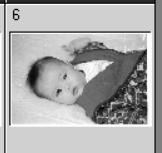
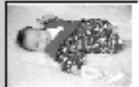
Tone-curve corrections
By selecting individual color channels on the tone curve, adjustments to the overall color of an image can be made. In this example, the image is too yellow. By moving the blue curve up, the image looks more neutral. For more on tone curve corrections, see page 50.
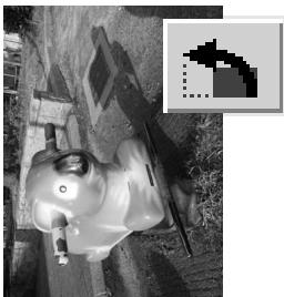
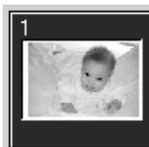
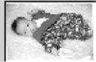
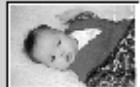
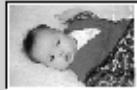
Digital ROC - Reconstruction Of Color
Original image

After Digital ROC processing
Digital ROC restores the color of old faded film, see page 45.
BEFORE YOU BEGIN
Thank you for purchasing this Minolta product. Please take the time to read through this instruction manual so you can enjoy all the features of your new scanner. Check the packing list in the scanner hardware manual before using this product.
The DiIMAGE Scan functions available vary between scanner models. To find the functions listed in this software manual that are not compatible with your scanner, see "Compatibility with the DiIMAGE Scan Utility" in the scanner notes section of the hardware manual.
If the operating system's display controls are set to a large font size, the text in the DiIMAGE Scan applications will not be displayed correctly. Use the computer's initial display text size.
This instruction manual does not provide instruction in the basic operation of the personal computers, nor the basic operation of Windows or Macintosh operating systems; refer to the manuals supplied with the computer.
The examples in this manual use Windows software. The appearance of the screens may differ from the examples when using Macintosh or other Windows operating systems. The screens can also vary with the scanner model.
Every precaution has been taken to ensure the accuracy of this material. Specifications in this manual are based on the latest information available at the time of printing and are subject to change without notice. Minolta is not responsible for any loss or damage caused by the use of this software. This instruction manual may not be copied either in part or in its entirety without the prior permission of Minolta.
Before installing the DiIMAGE Scan Utility
RAM-stationed programs such as anti-virus or installation-monitoring software may cause the installer to fail. Remove or disable these programs before installing the DiIMAGE Scan Utility. Reinstall or enable the software when the installation is complete.
The scanner hardware manual contains the system requirements for the purchased scanner unit; do NOT connect the scanner to a computer before installing the DiIMAGE Scan Utility software.
Microsoft, Windows, Windows 98, Windows Me, Windows 2000 Professional, and Windows XP are registered trademarks of the Microsoft Corporation. Macintosh, Apple, and Power Macintosh are registered trademarks of Apple Computer, Inc. Adobe and Photoshop are registered trademarks of Adobe Systems Incorporated. Digital ICE3, Digital ICE, Digital ROC, and Digital GEM are trademarks of registered trademarks and technologies of Applied Science Fiction, Inc in U. S. A. Other corporate and product names are the trademarks and registered trademarks of their respective companies.
TABLE OF CONTENTS
This manual contains information on the DiIMAGE Scan Utility software. See the supplied hardware manual for information on connecting the scanner to a computer and loading the film holders. The scanner notes section of that manual provides additional information on software operation for your particular model scanner.
Color examples 2
Before you begin 3
Before installing the DiIMAGE Scan Utility 3
Installation 6
Windows 6
Macintosh 8
Easy Scan Utility 10
Launching the Easy Scan Utility 10
Using the Easy Scan Utility 11
Basic scanning 14
Launching the DiIMAGE Scan Utility. 14
Scanning basics 14
Scanner setup 15
Main window and index scan tab 15
Making an index scan 16
Selecting index thumbnails 16
Flip and rotate images 17
Fit-to-window button 17
Main window and prescan tab 18
Making a prescan. 18
Grab tool. 19
Magnifying tool 19
Auto cropping 19
CHP button (APS film) 19
Making the final scan 20
Basic image processing 22
Main window and image-correction tab 22
Pixel Polish 23
Digital ICE - Image Correction Enhancement 24
Variation palette 25
Brightness, contrast, and color-balance palette 26
An introduction to color 27
Comparing pre and post-correction images 28
Undoing and redoing image corrections 28
Grain Dissolver 29
Quitting the DiIMAGE Scan Utility 29
Advanced scanning 30
Setting scanner preferences 30
Exposure control tab 32
Saving exposure settings 33
Loading exposure settings 33
More index scan functions 34
Reverse frame order 34
Saving the index thumbnails 35
Saving an index file 35
Loading an index file 35
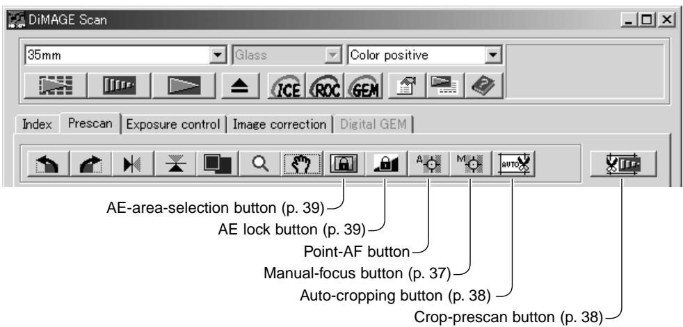
More prescan functions 36
Point AF (Autofocus) 36
Manual focus 37
Manual cropping 38
Autoexposure 39
AE area selection 39
AE lock 39
Inputting scan settings manually 40
About resolution and output size 41
Scan setting examples 42
Saving scan settings as a Job 43
Deleting a Job 43
Advanced image processing 44
More image-processing tools 44
Digital ROC - Reconstruction Of Color 45
Digital GEM - Grain Equalization & Management 46
Tone curve / histogram palette 48
Using tone curves 48
Drawing tone curves by freehand 49
A short guide to tone-curve corrections 50
Histogram corrections 52
Tone-curve / histogram auto setting 53
White, black, and gray-point corrections 54
Setting the white and black-point values 55
Tracking image corrections - snapshot button 55
Hue, saturation, and lightness palette 56
Selective-color palette 57
About RGB and CMY 57
Unsharp mask 58
Saving image corrections 59
Loading image-correction Jobs 59
Custom Wizard 60
Batch Scan Utility 62
Color matching 66
Setting the output color space 66
Output color spaces 67
Setting the monitor ICC profile 68
Scanner color profiles 68
Color matching recommendations 69
Appendix 70
Using multiple scanners 70
Uninstalling the DiIMAGE Scan software 70
Installed file and folders 71
Damage Scan Multi and Multi II system requirements 72
About the Dimage Scan Multi and Multi II 73
Record keeping 73
Image Data Sheet 74
Color examples 75
INSTALLATION
Windows
In the example below, the hard disk is drive C, and the CD-ROM drive is drive D. The letters designating the drives will vary between computers.
Turn on the computer to start up the Windows operating system.
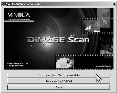
Insert the DiIMAGE Scan Utility CD-ROM into the CD-ROM drive. The DiIMAGE Scan Utility setup screen will open.
Click the "Starting up the DiIMAGE Scan installer" button. The program decompression screen will briefly appear. The Install Shield Wizard will start automatically.
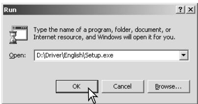
If the Install Shield Wizard does not start up automatically, execute the following procedure:
- Initiate the run routine on the start menu.
- Click the browse button in the run dialog box.
- Select the CD-ROM drive from the look-in box in the browse window.
- Open the driver folder.
- Open the English folder.
- Click on the Setup.exe file. It will be displayed with its location in the run dialog box:
D:\Driver\English\Setup.exe. Click OK.
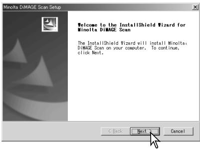
The opening screen of the InstallShield Wizard will appear. Click the next button to continue.
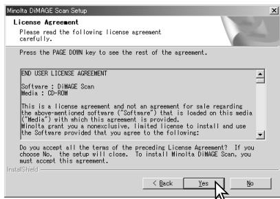
Click the yes button to accept the agreement and continue. Read the entire agreement carefully before continuing. If you do not agree to the terms of the license agreement, click the no button to exit the setup program.
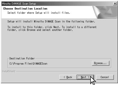
To install the software in the default folder (C:\Program Files\DiMAGEScan), click Next.
To install the software in another folder, click the browse button to display the folder selection window. Specify the directory in which to install the software, then click OK.
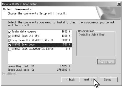
Select the components to be installed, then click the next button. The DiIMAGE Scan Launcher and Quick Scan Utility should only be installed with compatible scanners, see "Compatibility with the DiIMAGE Scan Utility" in the scanner notes section of the hardware manual. Normally, the TWAIN data source should be installed. The descriptions in this manual assume the utility was installed with the TWAIN data source.
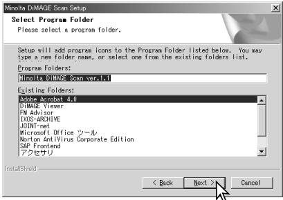
The name of the default program folder is displayed. To install the software in this folder, click Next.
To install the software to another existing folder, select one of the folders listed in the existingFolders box below. Click the next button to begin installation.
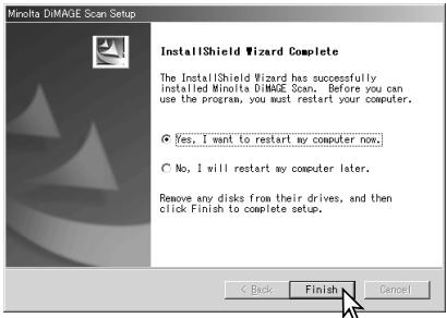
The InstallShield Wizard will indicate that installation was successful. Select the restart-computer option and then click Finish. When the computer restarts, the scanner driver software will be ready to use. Print out a copy of the Read Me file for reference.
The scanner software can be launched directly from most image-processing applications. Although the TWAIN driver cannot be seen, it allows the utility to be launched from an image-processing application using the import option as well as allowing the computer and scanner to communicate.
Macintosh
Turn on the computer to start the Mac OS. Insert the DiIMAGE Scan Utility CD-ROM into the CD-ROM drive. The Dimage Scan Utility CD-ROM icon will appear on the desktop. Double-click on the icon; the driver, manual, and acrobat reader folders will be displayed.
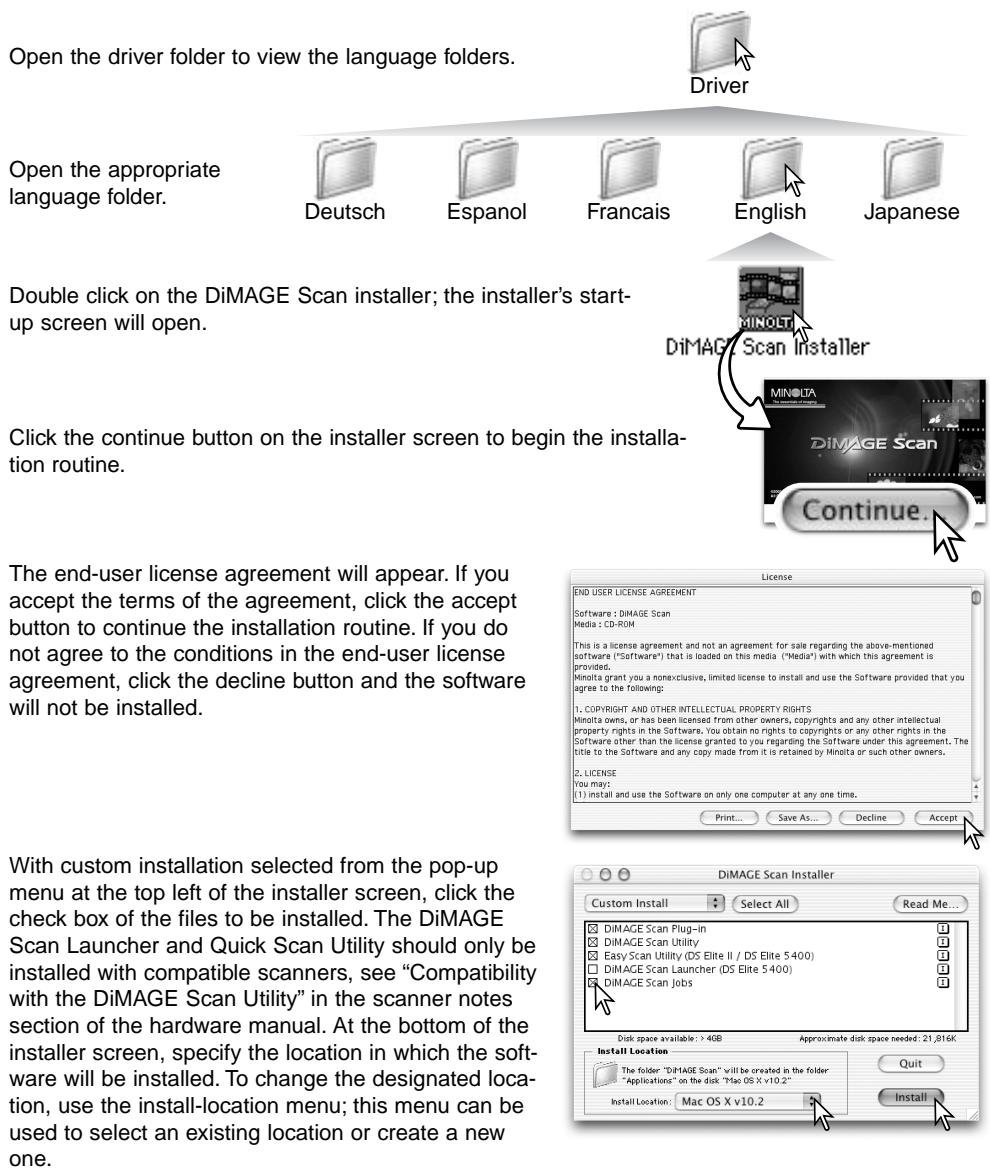
Click the install button to begin installation.
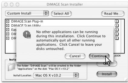
Any software that is running must be closed before the DiIMAGE Scan Utility can be installed. Click the continue button to shut down any active applications and continue the installation routine. The cancel option will end the installation routine.
A screen confirming the successful installation of the software will appear. Click the restart button to exit the installation program and restart the computer. The quit button exits the installer without restarting the computer. To make additional installations, click the continue button.

After the computer restarts, confirm the selected DiIMAGE Scan applications are installed in the designated location. Print out a copy of the Read Me file for reference.
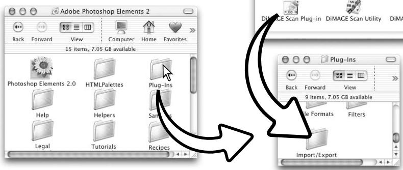
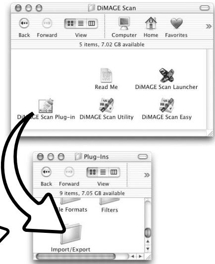
If the DiIMAGE Scan plug-in was installed, simply drag and drop the plug-in file into an image-processing application's import folder. This will allow the DiIMAGE Scan Utility to be launched directly from that application.
EASY SCAN UTILITY
The DiIMAGE Scan Easy Scan Utility is a simple, automatic scanning application for trouble-free scans. The utility works as a stand-alone program, and cannot be launched through another application. This software is not available with all scanner models, see the scanner notes section in the scanner hardware manual.
The following settings are automatically made when using the Easy Scan Utility:
- Autofocusing with each 35mm frame, or with the first APS frame only.
- Index scan priority: speed setting (p. 30).
Color depth: 8 bit. - No multi-sample scanning.
Automatic cropping to inside edge (p. 19). - When Digital ROC is active, color matching is turned off.
- sRGB output color space when color matching is on. (p. 66)
- Autoexposure with all films except black and white slides.
Launching the Easy Scan Utility
Do not launch the utility with a film holder in the scanner. If the scanner model has a manual front door, the door must be closed.
Macintosh
Open the DiIMAGE Scan folder. Double click the DiIMAGE Scan Easy icon.
DiAGE Scan Easy
Using the Easy Scan Utility
When the Easy Scan Utility is launched, the Easy Scan Wizard opens. Simply follow the instructions on the Wizard to scan images. Screens and functions differ between scanner models.
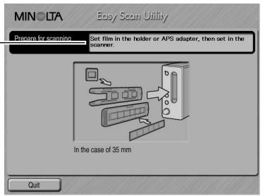
A screen requesting a film holder appears. Load and insert the holder following the instructions in the loading a film holder section of the hardware manual.
If an optional APS adapter is used, an index scan will be made and the next window is skipped. The APS auto-detect function automatically sets the film type between color and black and white, and positive and negative.
- The status bar at the top of each window gives instructions or describes function on which the mouse pointer is located.
To exit the Easy Scan Utility at any point, click the quit button in the bottom left corner of the window. The film holder will be ejected automatically.
Scanner Notes (Macintosh)
To cancel an index scan, prescan, or final scan once it has started, click and hold the mouse on the cancel button in the progress dialog box or press and hold the command and period (.) keys until the cancel button appears to depress.
When the index scan is complete, thumbnails of all the images in the holder are displayed. Click the image to be scanned. The border is highlighted to indicate selection. Only one image can be selected. When using an optional APS adapter, the thumbnail frame numbers correspond to the film frame numbers.
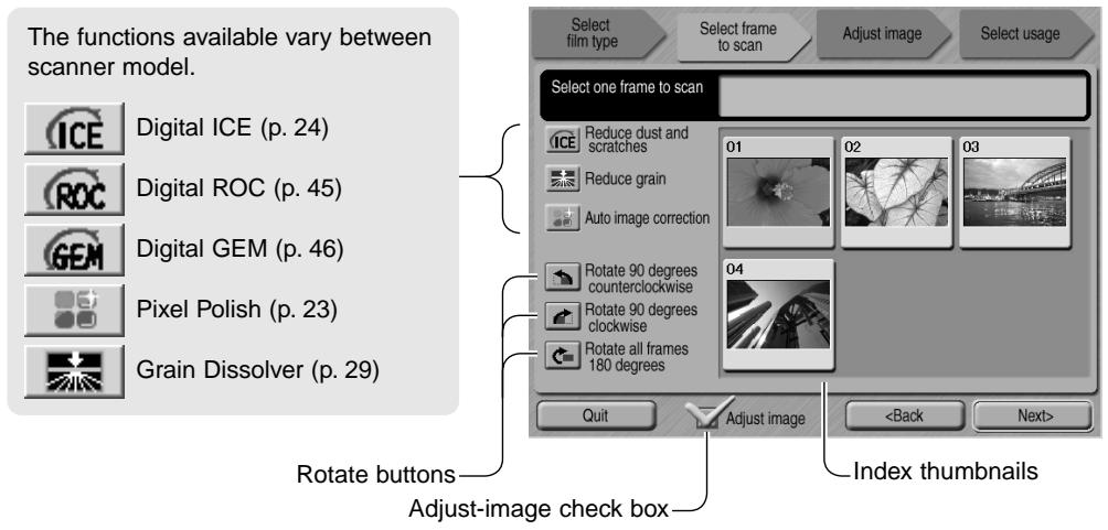
Once an image-processing function is selected, it will remain in effect until canceled. Not all the functions can be used with black and white film. The Grain Dissolver automatically activates with Digital ICE when both functions are available.
Click the adjust-image check box to access the adjust-image screen to control image brightness, contrast, and saturation. Uncheck the box to go directly to the select-usage screen.
When scanning with the optional APS adapter, more thumbnails will be created than can be displayed. Scroll buttons will appear at the side of the window. The single-arrow button scrolls one line at a time, the double-arrow button scrolls two lines.
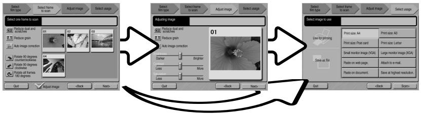
Select the image to be scanned. Select image processing or rotate the image as necessary. Click the next button to continue.
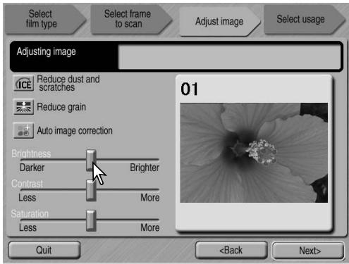
If the adjust-image option was checked in the previous screen, the adjust-image screen will be displayed. The same automatic image-processing functions shown in the previous screen are also displayed here.
Click and drag the brightness, contrast, and saturation sliders to adjust the image; change are reflected in the display. Any changes made to brightness, contrast, and saturation will remain in effect until reset or the utility is closed. Returning to the previous screen and unchecking the adjust-image box will not reset these settings.
After making adjustments to the image, click the next button.
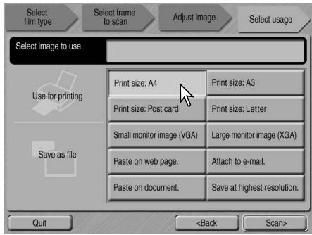
Select the option which best describes the final use of the scanned image. Only one choice can be made. Click the scan button to continue; the save-as screen will open. If an image has multiple uses, repeat the Easy Scan procedure for each use of the image.
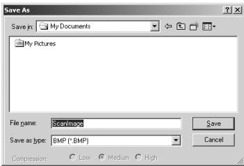
On the save-as screen, specify the file name, file format, and destination of the image data. Images can be saved in BMP, JPEG, TIFF, or PICT file formats. See page 21 for more about these formats. When saving JPEG files, the compression ratio can be specified. Click the save button to complete the final scan.
When using a USB storage device on the same bus as the scanner, save the data on the computer's hard disk first before transferring it to the storage device. Saving the scanned data directly to the device may corrupt the image data.
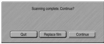
After the scanning is completed, the image is ready to use. Click the appropriate button to continue or close the utility. The quit button closes the Easy Scan Utility and ejects the film holder. The replace-film button ejects the holder so the film can be changed. The continue button allows other images in the film holder to be scanned. Turn off the scanner when not in use.
BASIC SCANNING
Launching the DiIMAGE Scan Utility
Do not launch the utility with a film holder in the scanner. If the scanner model has a manual front door, the door must be closed. The utility can also be launched from an image-processing application. See the Windows and Macintosh installation section.

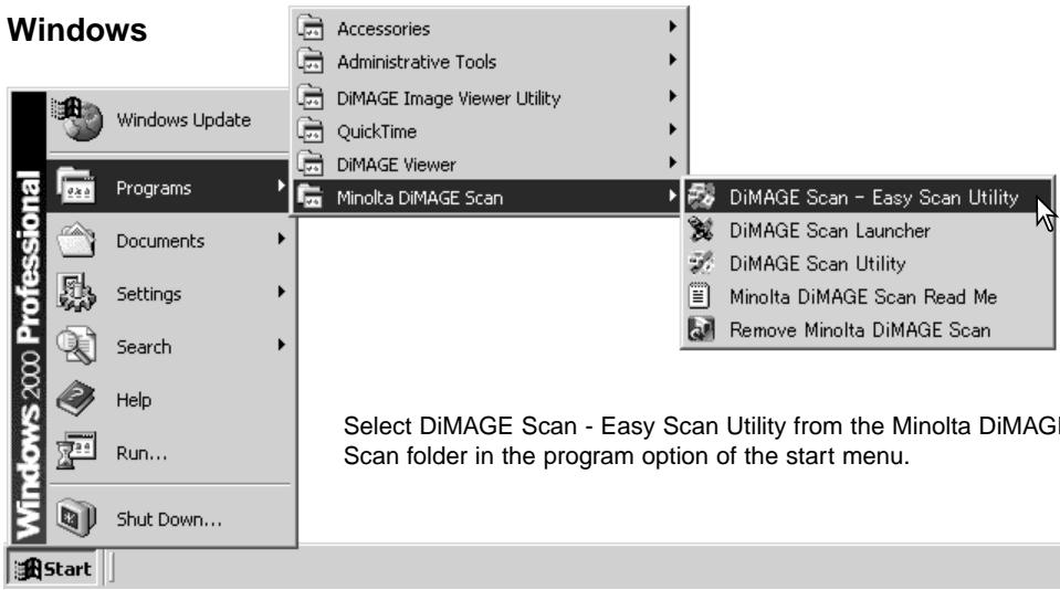
Select DiIMAGE Scan Utility from the Minolta DiIMAGE Scan folder in the program option of the start menu. See page 70 when using multiple scanners.
Macintosh
Open the DiIMAGE Scan folder, and double click the DiIMAGE Scan Utility icon. See page 70 when using multiple scanners.
DiAGE Scn Utility
Scanning basics
Please read the basic scanning section in its entirety before moving on. Before any scan is made, the film holder must be loaded and inserted into the scanner. Refer to the scanner hardware manual for instructions as well as film handling tips.
Three types of scans can be made singularly or in combination depending on the workflow and degree of processing:
| Index scan | To display thumbnails of each image in the 35mm or APS film holder. An index scan is useful when scanning multiple frames on one film strip or for selecting a specific frame among similar images. |
| Prescan | To display a preview of a specific image. A prescan allows an image to be cropped or corrected using the DiIMAGE Scan's image-processing tools. |
| Scan | To save and export an image. Image size, resolution, and file format are spec-ified with this scan. |
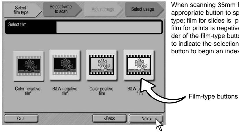
Scanner setup
Before making a scan, the film format and type must be specified. Refer to the film format and type settings section of the hardware manual for more information.
Film format and type are selected from the drop-down menus in the top left corner of the main window. If the holder and selected film format do not match, a warning will be displayed and the scan will not be made.
Some model scanners use both glass
and glassless film holders, see the scanner notes section in the hardware manual. This must be set with the holder type drop-down list.
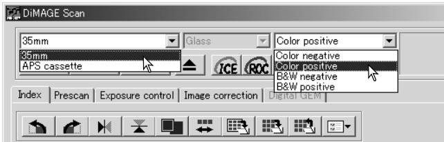
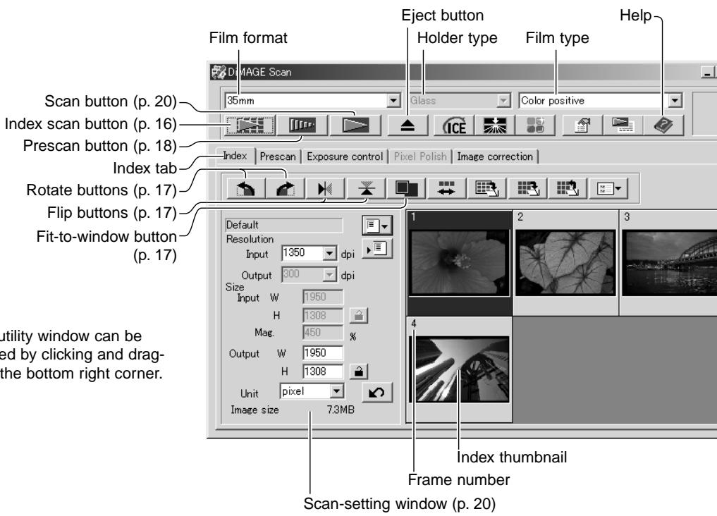
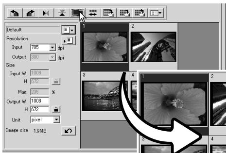
Main window and index scan tab
Making an index scan
Index scans can be made of 35mm or APS film. An index scan cannot be made with single-frame medium format film holders. The type of film holder available vary with scanner model.
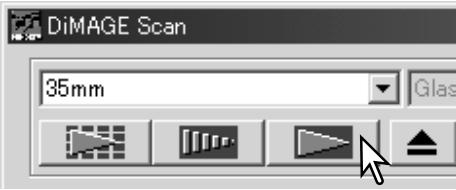
With a loaded film holder in the scanner, click the index-scan button in the main window to start
the scan. All the frames in the film holder will be scanned. The frame number of the index scan corresponds to the frame number in the film holder. Images can be prescanned or scanned without making an index scan.
To cancel the index scan, click the cancel button in the small dialog box that appears during the scan, or press the escape key (Windows), or press the command key and period (.at the same time (Macintosh).
Index thumbnails will remain in the display until another index scan is made or the film format and type are changed. To initialize the index display and remove the current thumbnails press the control key (Windows) or command key (Macintosh) together with the shift and R keys.
Selecting index thumbnails
The thumbnail display allows the selection of single or multiple images for prescanning or scanning. Selected images can also be affected by the scanner software functions such as the rotate buttons.
Simply click on a thumbnail to select it; the border will darken to indicate selection.
To select multiple images, press and hold the control key (Windows) or command key (Macintosh) and then click on each image to be scanned; the selected frames will have a dark border. To deselect an image, click on the thumbnail a second time while holding the con
trol key (Windows) or command key (Macintosh). To select consecutive images, press and hold the shift key and then click on the first and last images of the series. Press the control key (Windows) or command key (Macintosh) and A key at the same time to select all frames.
Flip and rotate images
The orientation of the index thumbnails and prescan images can be changed with the flip and rotate buttons on the tool bar.


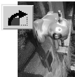
Rotate - the rotate-right button rotates the thumbnail 90^ clockwise and the rotate-left button rotates the image 90^ counterclockwise each time the buttons are clicked.
Original image
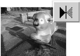
Flip - when an image is flipped, it will create a mirror image.
Fit-to-window button
Normally, index thumbnails and prescan images are displayed based on their size and resolution. When the number of thumbnails or the size of the prescan is too large or small for the display area, clicking the fit-to-window button automatically resize the images to fit the display area. Clicking the button again displays the images at their original size. The prescan grab and zoom tools cannot be used with the fit-to-window function.
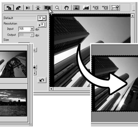
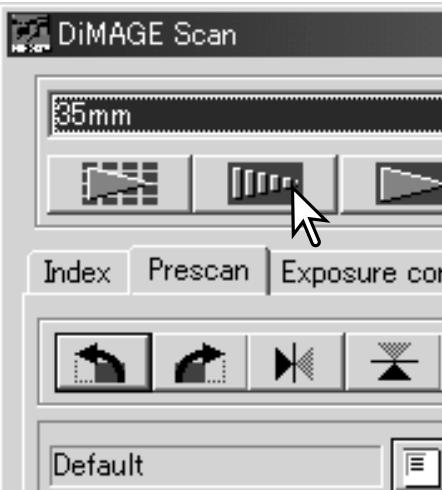
Main window and prescan tab
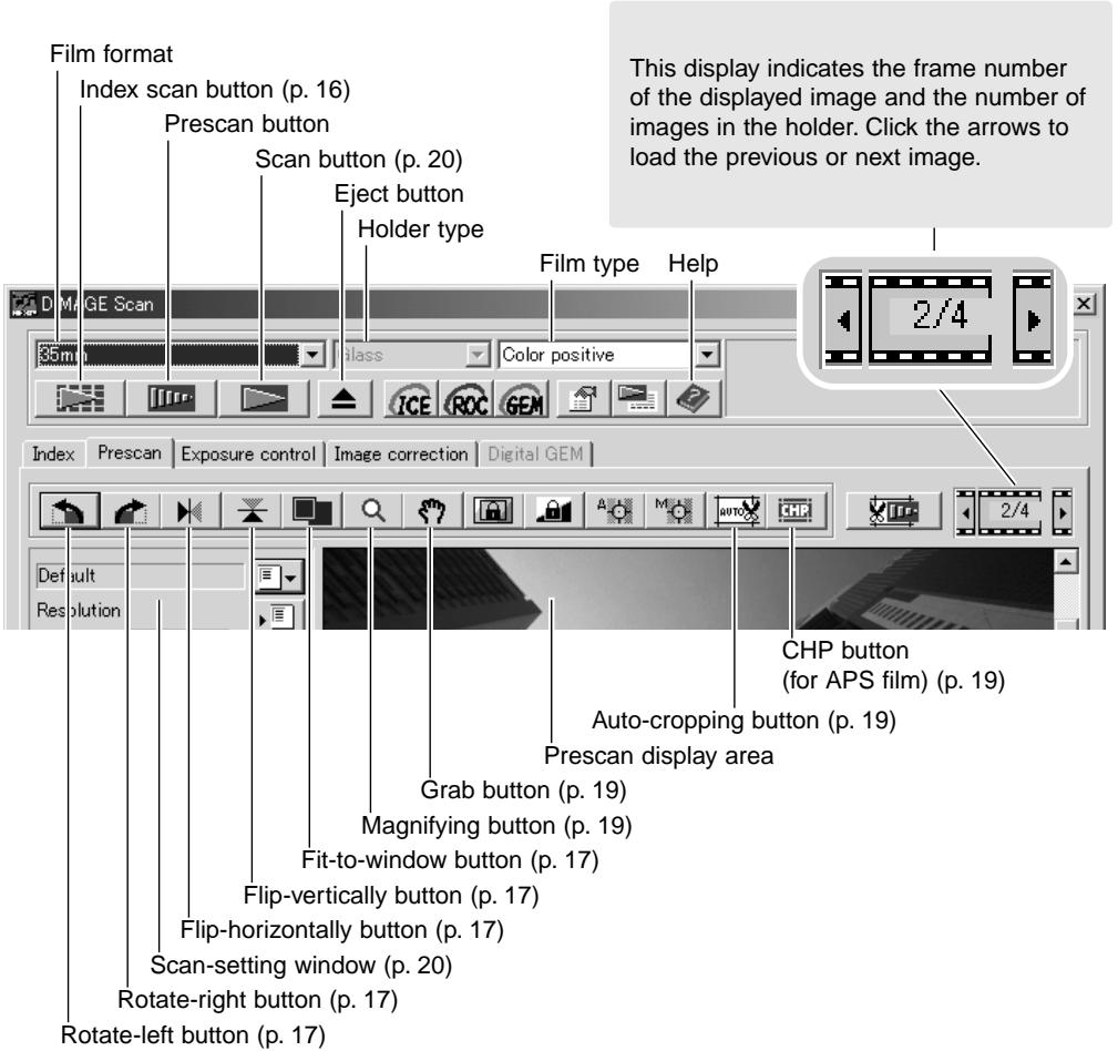
Making a prescan
When using an index scan, select the index frame to be prescanned. Click the prescan button in the main window. Double clicking on the index frame will also activate the prescan even if no thumbnail is displayed in the frame; the prescan window will be displayed automatically.
When using a single-frame medium-format film holder, click the prescan button in the main window.
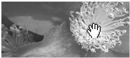
Grab tool
When an image is larger than the display area, the grab tool can be used to scroll the image. Click the grab button on the tool bar. Click and drag on the image to scroll. This tool cannot be used with the fit-to-window function (p. 17).
Magnifying tool
The display image can be enlarged or reduced. Click the magnifying button on the tool bar. Click on the image to enlarge. To reduce, hold down the control (Windows) or option key (Macintosh) and click on the image. When the image has reached the magnification limit, the plus or minus sign in the magnifying icon will disappear. This tool cannot be used with the fit-to-window function (p. 17).
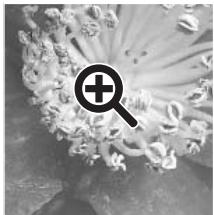
Enlarge
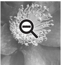
Reduce
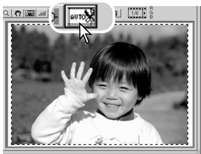
Auto cropping
Auto cropping eliminates the blank space around the image area. Clicking the auto-cropping button cycles through its three positions: crop to outside edge of the image area, crop to inside edge of the image area, and entire scan area. The cropping frame is indicated by a marquee (dotted line). The cropping area can also be adjusted manually (p. 38). When using the image-correction tools, only the cropped area is displayed.
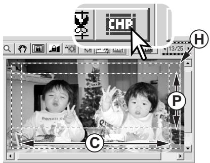
CHP button (APS film)
Scanner models that accept optional APS adapters can use the CHP button to crop an image to one of the APS formats. Clicking the CHP button cycles the cropping frame through the C, H, and P APS framing formats. The cropping area can be moved by placing the mouse pointer within the marquee (dotted line) and then clicking and dragging. The cropping area can also be adjusted manually (p. 40). When using the image-correction tools, only the cropped area is displayed.
Making the final scan
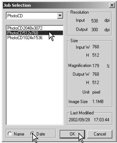
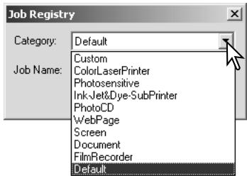
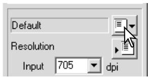
Before making the final scan, the input and output parameters must be specified. While it's possible to input the scan settings yourself, DiIMAGE Scan Utility gives you an easier choice - the Job function. This function automatically loads the scan settings based on the final use of the image. The scan-setting dialog box is located on the left of both the index scan and prescan windows.
The Standard Scan Utility contains over 100 Job files to cover a wide range of image use. To create your own Job files or to input the scan settings manually, see page 40. For a list of Job parameters, see the Job file lists section in the scanner hardware manual.
- Size is based on the total number of pixels in the image and can be different from the size of the saved data depending on the file format selected.
Click the load Job button. The Job-selection dialog box will open.
Select a Job category from the drop-down list. The Job categories will vary between scanner models.
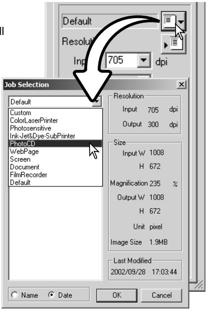
Click a Job file name to select it. The Job names can be sorted chronologically or alphabetically by clicking the name or date radio buttons at the bottom of the dialog box.
The scan settings of the selected Job file are displayed on the right side of the window. The Job settings vary with the film format. Click the OK button to apply the Job settings.
When the Job file is loaded, a cropping frame will appear on the image. The frame is proportional to the output use specified with the Job. The frame can be resized, but the proportions will remain the same; the input and output values are automatically adjusted to match the change to the cropping frame.
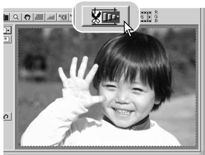
Click the scan button in the main window to start the final scan. If the DiIMAGE Scan Utility was opened in an image-processing application, the scanned image will be opened in that application. If the utility is used by itself, the save as dialog box will open.
On the save-as dialog box, enter the file name, and select the file destination and file format for the image data. If multiple images are scanned, a serial number can be added to the file name automatically; click the add-number check box and then enter the first number of the series. When saving JPEG files, the compression ratio must be specified. Click the save button to make the final scan.
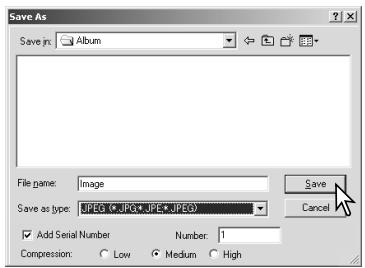
| File types | |
| JPEG | This file can be compressed to reduce the file size. The compression ratio can be select- ed when saving. The higher the compression ratio, the smaller the file size, and more loss to image quality. |
| TIFF | A high-resolution bitmap that can be opened on any computer platform. The color depth can be specified in the preference window (p. 30). |
| BMP | A file type used in Windows. This file type can be opened in the paint software installed in the Windows operating system. |
| PICT | A file type used in Macintosh. This file can be opened in the Simple Text application installed with Macintosh operating systems. The file cannot have a width greater than 4096 pixels. |
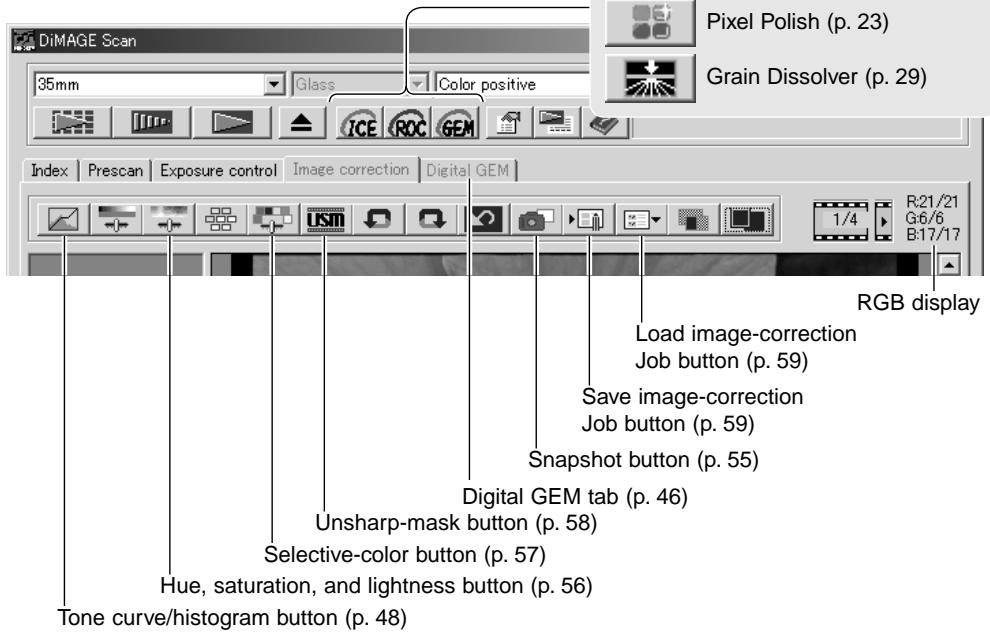
BASIC IMAGE PROCESSING
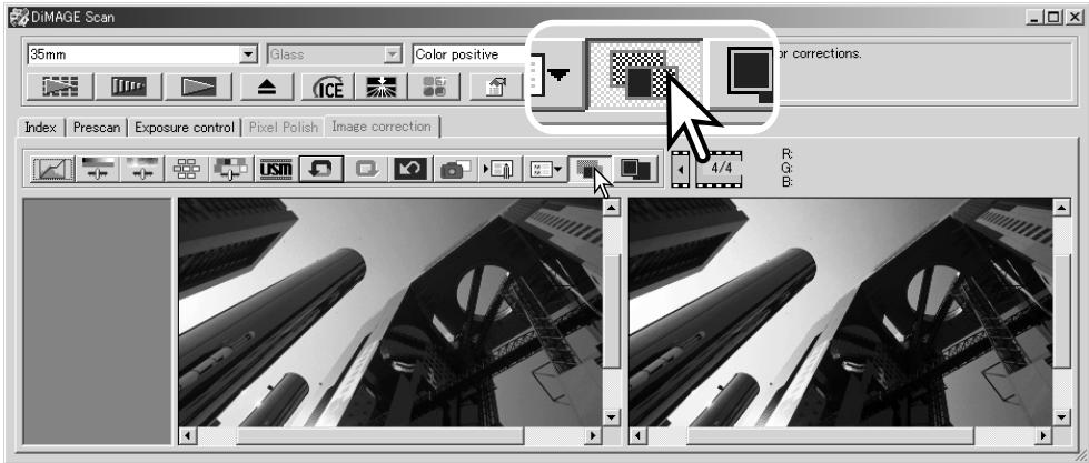
Main window and image-correction tab
This section contains details on the basic image-processing tools. For descriptions of the advanced tools, see pages 44 though 59. The prescan image or a selected index image can be displayed in the image correction window by simple clicking the tab. If the image has not been prescanned, a prescan will be made automatically.
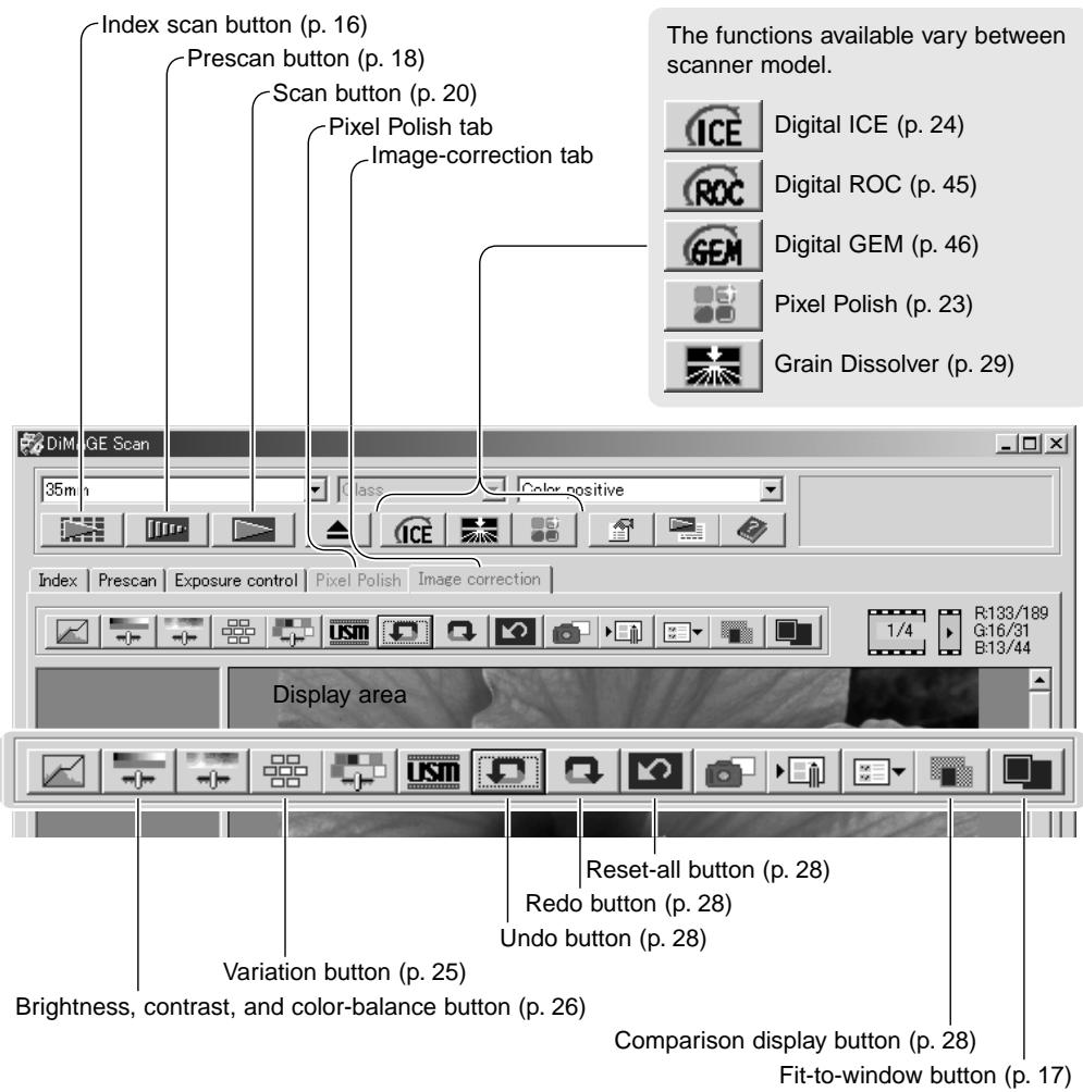
The utility window can be resized by clicking and dragging the bottom right corner. If the fit-to-window function is active, the displayed image will automatically adjust to fit the display area. If any changes are made to the image using Pixel Polish or the image-correction tab, the tab will turn red (Windows) or an asterisk will be displayed (Macintosh).
Pixel Polish makes automatic or custom image corrections. This function is not available with all scanner models. See the scanner notes section in the hardware manual for compatibility and system requirements. Pixel Polish cannot be used with black and white film, 16-bit or 16-bit linear color depth (p. 30). Scanning time increases. The effect of Pixel Polish is based on the prescan image area. If the image is cropped after applying Pixel Polish, click the crop-prescan button (p. 38) to view the results.
Click the Pixel Polish button in the main window to automatically correct the images in the film holder; previous corrections are canceled. The correction is applied to the prescan image.
Pixel Polish remains in effect until canceled; click the Pixel Polish button again. To reapply image corrections made before using Pixel Polish, open the image in the image-correction tab and click the undo button.
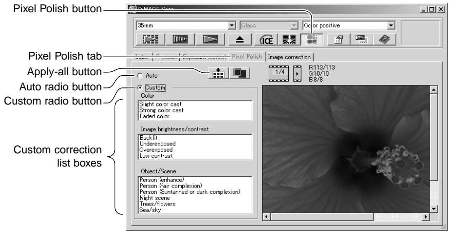
To make custom corrections, click the Pixel Polish tab. If a prescan has not been made, the scanner will make one automatically.
Click the custom radio button. Click on the descriptions in the list boxes which best describes the image. To deselect a description, click on it again (Windows) or press the command key and click on it (Macintosh).
The apply-all button applies the custom settings to all images in the film holder. To reset the images to the auto correction setting, click the auto radio button and then the apply-all button.

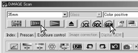
Digital ICE - Image Correction Enhancement
Digital ICE reduces the effects of surface defects, dust, scratches, fingerprints, mold, etc., from the film image during scanning. The scanning time increases with the use of Digital ICE. The Grain Dissolver automatically activates with Digital ICE when both functions are available.
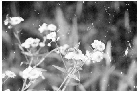
Original image
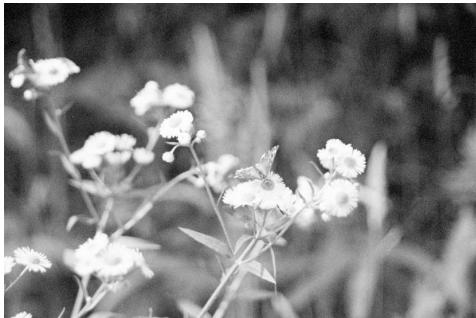
After Digital ICE processing
Click the Digital-ICE button to activate the function. Press the prescan button to view the results.
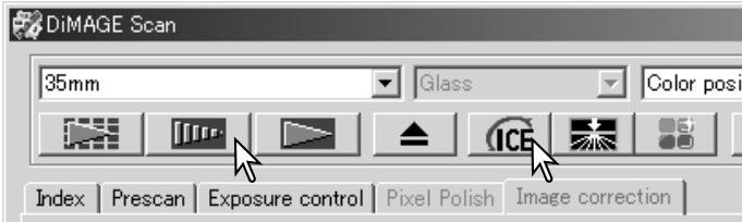
Digital ICE processing is applied to the prescan and final scan. To turn off Digital ICE, click the Digital-ICE button again. Each time the Digital ICE button is pressed, the prescan image is deleted and another prescan needs to be made.
Digital ICE cannot be used with Kodak Kodachrome film or traditional silver-halide black and white films. Special black and white films that are designed to be developed in a C-41 or equivalent color process, Kodak Select Black & White 400, Kodak T400CN, or Ilford XP2 Super, can be processed with the Digital ICE function. These films should be scanned with the color-negative film-type setting. Results cannot be guaranteed with other types of black and white film.
The undo, redo, and reset-all buttons have no effect with the Digital ICE3 functions.
Variation palette
The variation palette allows an image to be corrected by comparing it to other slightly corrected images surrounding it. This is an easy method to correct images for individuals who are inexperienced in image processing or photofinishing.
Click the variation button to display the palette.
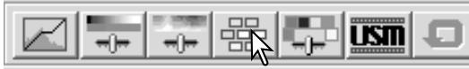
Click the arrow next to the variation list box (1) to select the image quality to be corrected: color balance, brightness and contrast, or saturation. Each variation palette shows the current image in the center with corrected samples displayed around it.
Click the best image among the frames (2). The selected image becomes the new center surrounded by a set of new images and the change is applied to the prescan image. This procedure can be repeated until the desired correction is obtained. Click the reset button to cancel all changes.
The difference between the samples can be changed. Drag the variation-step slider, or enter a value into the text box to set the degree of correction. The initial setting is 10. The correction step can be set between 1 and 20.
Checking the display-limit check box will indicate when any of the image values exceed 0 (black limit) or 255 (white limit) with the complementary color. For example, if the blue area of the image exceeds those values, the limit is displayed with the complementary color, yellow.
Click the close button to close the palette and apply any image corrections.
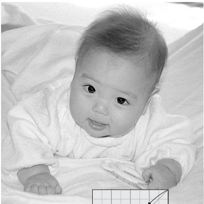
Brightness, contrast, and color balance palette
Click the brightness, contrast, color-balance button to display the palette.


Drag the brightness, contrast, or color sliders, or enter specific values in the corresponding text box to make corrections. Dragging each slider to the right or inputting a positive number in the text box increases the brightness, contrast, and color.
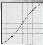
Changes will be reflected in the displayed image and in the graph at the top of the palette. The horizontal axis of the chart indicates the original image values and the vertical axis the new values. Click the reset button to cancel all changes.
Clicking the auto-setting button corrects the brightness and contrast automatically without affecting the color balance. Click the reset button to cancel the changes.
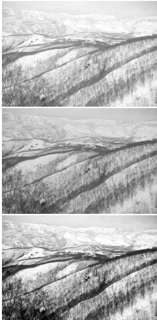
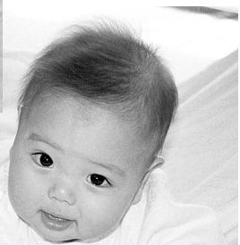
Is this picture too light? Adjusting brightness and contrast can be more difficult than it looks. The image on the right looks too bright, especially the mountains in the background.
Simply making everything darker with the brightness controls creates a muddy image - the snow and sky are a dull gray and there are no strong blacks.
By adding contrast to the image, the snow is brightened while the darker trees are accentuated. The extra contrast also gives the image the appearance of being sharper as well as revealing fine details.
An introduction to color
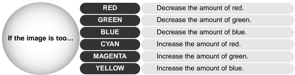
In photography, red, green, and blue are the primary colors. The secondary colors, cyan, magenta, and yellow, are made from combining the primary colors: cyan = blue + green, magenta = blue + red, and yellow = red + green. The primary and secondary colors are grouped in complementary pairs: red and cyan, green and magenta, and blue and yellow.
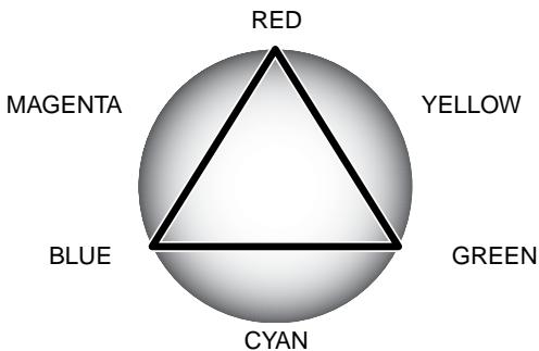
Knowing the complementary colors is very important in color balancing. If the image has a specific color cast, either subtracting the color or adding its complementary color will create a natural looking image.
Adding or subtracting equal parts of red, green, and blue will have no affect on the color balance. However, it can change the overall image brightness and contrast. Usually, no more than two color channels are needed to color balance an image.
Color balancing is a skill that develops with practice. While the human eye is extremely sensitive in making comparative judgements, it is a poor tool when making absolute measurements of color. Initially, it can be very difficult to distinguish between blue and cyan, and red and magenta. However, adjusting the wrong color channel never improves an image; subtracting blue from an image that is too cyan will give a green cast to the image.
Comparing pre and post-correction images
Clicking the comparison display button divides the image display area in two. The original image is on the left and the corrected image is on the right. To display the corrected image only, click the comparison display button again.
Original image
Corrected image
Changes made with the magnifying tool, grab tool, or scroll bars on one image will be applies to the other. Using the fit-to-window button automatically resize both images to fit the display area.
Undoing and redoing image corrections
The undo, redo, and reset-all buttons only affect tools used in the image-correction tab. They have no effect with the Digital ICE3 functions.

Click the undo button to cancel the last image correction applied to the image. The number of image corrections that can be undone depends on the computer memory capacity.

Click the redo button to reapply the last image correction canceled with the undo button.

Click the reset-all button to cancel all image corrections applied to the image.
This function is not available with all scanner models, see the scanner notes section in the hardware manual. The Grain Dissolver uses a diffusion plate in front of the light source to optically minimize the effect of grain. The Grain Dissolver automatically activates with Digital ICE when both functions are available.
How much the image is affected depends on the scanner resolution and film, film density, and image detail and can only be seen in the final scan. The Grain Dissolver increases scanning time. Contrast and sharpness may be affected. The use of autofocus or manual focus is recommended.
Click the Grain Dissolver button in the main window to activate the function.
Quitting the DiIMAGE Scan Utility
To close the DiIMAGE Scan Utility, simply click the close button in the top right corner of the main window.
ADVANCED SCANNING
This section covers the advanced scanning tools in the DiIMAGE Scan Utility. The basic scanning section on pages 14 through 21 should be read before continuing.
Setting scanner preferences
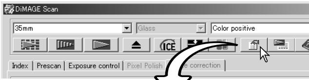
Click the preferences button in the main window to open the preferences dialog box. Select preferences options to customize scanner operations.
Exposure control for negatives:
autoexposure adjusts the scan to compensate for the density of the negative. The manual setting uses a fixed exposure regardless of the density of the film. Manual exposure can show the exposure difference in a bracket series. When using AE lock or AE area selection with negatives (p. 39), the auto function must be selected.
Auto-expose-for-slides check box:
to use autoexposure when scanning slides. Since the density range of slides is relatively uniform, adjusting the expose for each slide is usually unnecessary. However, when scanning an underexposed or overexposed slide, the autoexposure system can com
pensate for the unusual image density. When using AE lock or AE area selection with slide film (p. 39), the auto-expose-for-slide box must be checked.
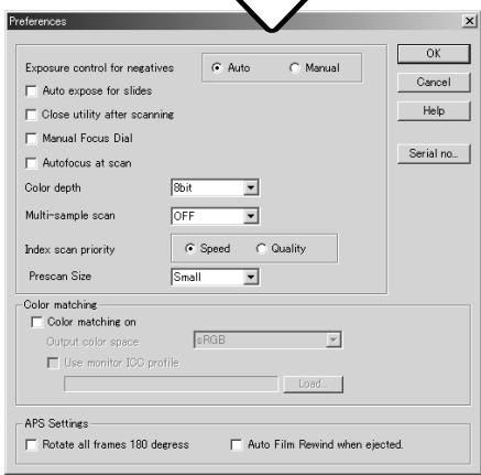
Close-utility-after-scanning check box:
this option closes the DiIMAGE Scan Utility after the final scan when using the scanner with an image-processing application. Activate this function when individual images will be scanned and then processed or retouched in another application. Uncheck the box when multiple images need to be scanned before retouching.
Manual Focus Dial:
for scanner models with a manual focus dial. See hardware manual for compatibility and use.
When the manual focus dial is active, autofocus and Point AF cannot be used.
Autofocus-at-scan check box:
this option activates the autofocus function during the prescan and final scan. When using Digital ICE, ROC, GEM, or Grain Dissolver, the use of autofocus is recommended. The autofocus function increases the scanning time.
Color-depth list box:
this option specifies the color depth of the scanned image between 8 bit, 16 bit, and 16-bit linear for each RGB channel. Because 16-bit linear color depth does not make any gamma corrections, the scan of a negative will produce a negative image. 16-bit and 16-bit linear images can only be saved in the TIFF file format. Some image-processing application cannot open 16-bit image files.
Multi-sample list box:
multi-sample scans reduce random noise in the image by analyzing the data of each sample scan; 2, 4, 8, and 16 samples can be made. The more samples taken, the less random noise in the image and the longer the scanning time.
Index-scan-priority radio button:
this option allows the selection of high-speed index scans or a quality index scans with prescans.
Simply click the appropriate radio button.
| Speed | Only makes index thumbnails. Autofocus is disabled during the index scan. |
| Quality | Makes an index thumbnail and prescan of each image. Scanning time is increased. |
Prescan size:
only available with certain model scanners, see the scanner notes section in the hardware manual. To change the size of the prescan image.
Color matching:
this controls color reproduction on output devices such as monitors and printers. For detailed information, see the color matching section on page 66.
Rotate-all-frames-180-degrees check box:
for scanners that can use the optional APS film holder, refer to the scanner's hardware manual.
This option rotates all APS index frames 180 degrees in the index scan window.
Auto film rewind when ejected:
for the Dimage Scan Multi and Multi II model scanners when using the optional APS film holder. This option rewrites the film when the eject button is used. Uncheck this box if switching between multiple holders when the same APS film will be scanned.
Serial no. button:
for the Dimage Scan Multi II scanner only. This routine allows the scanning resolution to be increased to 2820 dpi when scanning medium-format film and Digital ROC and GEM to be used. Click the serial-number button to open the serial number window. Enter the serial number of the software and click OK to complete the operation.
OK button:
to apply the preference settings and close the window.
Cancel button:
to cancel any settings made and close the window.
Help button:
to open the help window.
Exposure-control tab
The exposure-control tab allows the scanner's exposure system to be customized to specific films, lighting, or a personal exposure index based on the film, processing, lens, and shutter combination. This can also be used to compensate for badly exposed film.
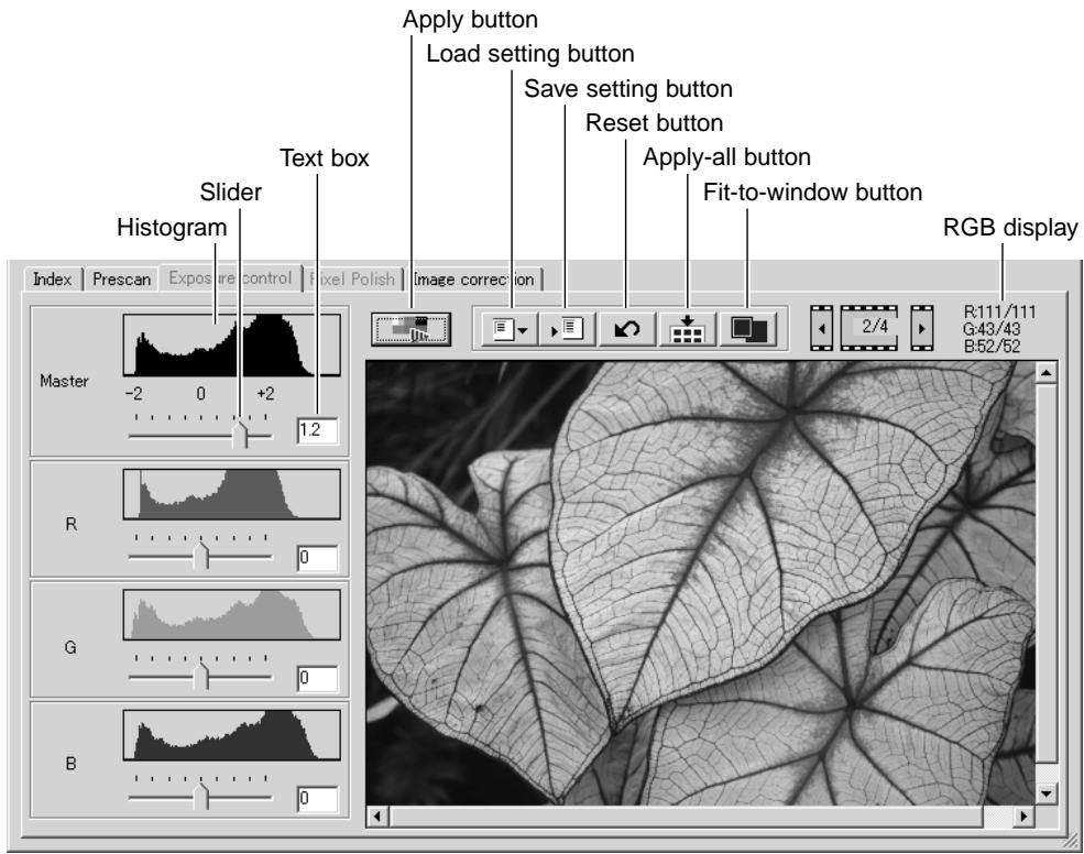
Simply click the exposure-control tab to display the selected image. If a prescan has not been made, the scanner will make one automatically. If any changes are made to exposure, the image-correction tab will turn red (Windows) or an asterisk will be displayed on the tab (Macintosh).
The RGB display will show the color values for any point in the image; simply place the mouse pointer in the image area to see the values of that point. Pressing the shift key (Windows) or command key (Macintosh) will display the CMY values.
The master slider and text box control the overall exposure. The R, G, and B sliders and text boxes are used to compensate for any color shift. No gamma or contrast changes can be made.
Adjust the sliders or enter values between ± 2 in 0.1 increments in the text boxes. Press the apply button (1) to view the effect on the preview image and the histograms. Repeat until the desired result is achieved. To cancel all settings, click the reset button and press the apply button to initialize the preview image.
When using autoexposure, adjustments are made in reference to the exposure determined by the AE system. To calibrate the scanner in reference to a standard exposure, turn the autoexposure functions off in the preference window (p. 30); set exposure control for negatives to manual or uncheck the auto-expose-for-slides check box. This is recommended when making settings for specific films.
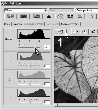
Click the apply-all button to use the exposure-control settings for all the images in the film holder. To cancel changes to exposure once the apply-all function has been used, click the reset button and then click the apply-all button again.
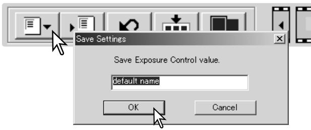
Saving exposure settings
Click the save setting button to open the save window.
Enter the name for the setting file. Click OK.
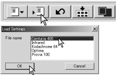
Loading exposure settings
Click the load setting button to open the load window.
Click on the file name to highlight it. Click OK to apply the settings to the image displayed in the exposure-control tab. Confirm the autoexposure settings in the preferences window (p. 30).
To delete a setting file, open the load window and click on the file name to highlight it. Use the keyboard delete key to erase the file.
More index scan functions

DiIMAGE Scan
35mm


Glass


Color positive


Index
Prescan
Exposure control
Pixel Polish
Image correction


Reverse-frame-order button
Save index-image button (p. 35)
Save index-file button (p. 35)
Load index-file button (p. 35)
Load image-correction Job button (p. 59)
Reverse frame order
Some cameras reverse-wind the film so the last frame is exposed at the beginning of the roll. When scanning film strips, the order of the index thumbnails can be reversed to correct the chronology by simply clicking the reverse-frame-order button. When the reverse-frame-order button is clicked again, the frame order follows the film holder frame order.
2
5
6
3
4

6
E

5
4
3
2
1
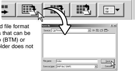
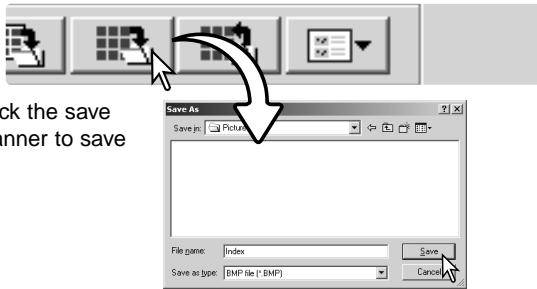
Saving the index thumbnails
The displayed thumbnail images can be saved in one image file. All the frames in the film holder, including empty frames, must be scanned before the index thumbnails can be saved.
Click the save index-image button. The standard save-as dialog box will appear.
Enter the file name, and select the file destination and file format for the image data. Click the save button. File formats that can be selected with Windows operating systems are Bitmap (BTM) or JPEG, and with Macintosh, Pict or JPEG. The film holder does not have to be in the scanner to save the images.
Saving an index file
The index thumbnails can be saved as an index file. The index file can be loaded into the scanner so that the index scan does not need to be made again. The index image file format is unique to this software. All the frames in the film holder, including empty frames, must be scanned before the index file can be saved.
Click the save index-file button. The standard save-as dialog box will appear.
Enter the file name and select the file destination. Click the save button. The film holder does not have to be in the scanner to save the file.
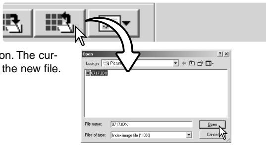
Loading an index file
An index file can be displayed in the index window of the utility software.
Click the load index-file button. The open dialog box will appear.
Select the index file to be loaded. Click the open button. The current index display will be replaced with the images in the new file.
More prescan functions
Scanner Notes
The DiIMAGE Scan autofocus system uses the CCD sensor to focus the scanner. When the autofocus-at-scan option is selected in the preferences window, the autofocus system uses the center of image to determine focus. This normally results in an excellent scan when the film plane is flat. However, if the film is warped or curled, the scanner can be focused using point AF or manual focus.
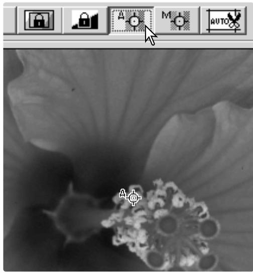
Point AF (Autofocus)
For best results when using point AF, select an area within the image with contrast or detail. The point AF function cannot focus on a low-contrast area such as a cloudless or overcast sky.
Click the point-AF button. The mouse pointer will change to the point-AF cursor. To cancel the function, click the point-AF button again.
Click on the area of image to be used for focus. Autofocus will begin and a new prescan will be displayed.
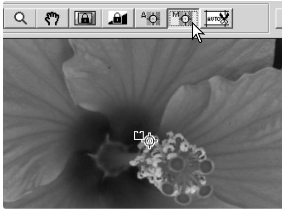
Manual focus
The scanner can be focused manually using the focus meter. For best results, select an area within the image with contrast or detail. The manual focus functions cannot focus on a low-contrast image such as a cloudless or overcast sky. Some scanner models can be focused with a manual focus dial, see the hardware manual for compatibility and instruction.
Click the manual-focus button. The mouse pointer will change to the manual-focus cursor. To cancel the function, click the manual-focus button again.
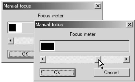
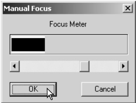
Click on the area of image to be used for focus. The focus meter window will appear.
Adjust the slider using the mouse until the black and white bars are at their longest extension. The black bar indicates the change in focus. The white bar indicates the longest extent of the black bar and the point of sharpest focus.
Click OK to set the focus. A new prescan will start and replace the previous image.
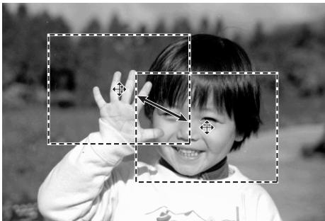
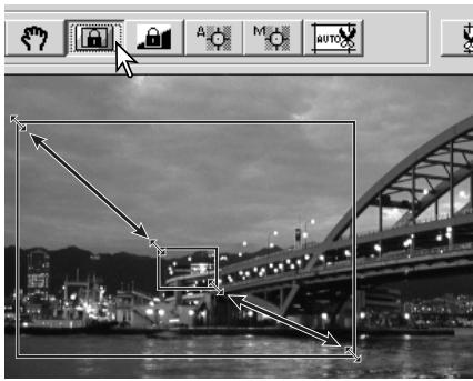
Manual cropping
Cropping is a method of recomposing the image by eliminating unnecessary space around the subject. Many images are improved by cutting out distracting elements in the background.
Clicking the auto-cropping button to display the cropping frame marquee.
To enlarge or reduce the cropping frame, place the mouse pointer over the corners or sides of the cropping frame; the pointer will change to a double arrow. Simply click and drag the edge of the frame to adjust the cropping area.
To move the cropping frame, place the mouse pointer in the center of the cropping frame; the pointer will change to a four-pointed arrow. Simply click and drag the entire frame over the image area.
With the pointer is outside the cropping frame, click and drag to define a new cropping frame.
Pressing the auto-cropping button again resets the cropping frame around the image area. The cropping frame can be reset to cover the full prescan area by pressing the control key (Windows) or the command key (Macintosh) and A key at the same time.
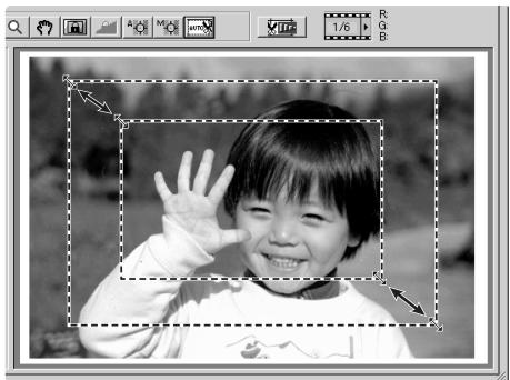
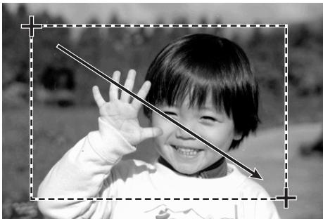
Click the crop-prescan button to make a prescan of the cropped area. To cancel the cropping, press the prescan button.
Autoexposure
When AE area selection or AE lock are used with slides, the auto-expose-for-slides option must be checked in the preferences box. When used with negatives, the exposure control for negatives must be set to auto in the preferences box (p. 30).
AE area selection
AE area selection allows the use of a small area within the image to determine the scan exposure. Use AE area selection with high or low-key images, or when the film has been badly exposed.
Click the AE-area-selection button after prescanning the image.
Pressing the shift key changes the dotted cropping frame to the solid AE area frame. While pressing the shift key, use the mouse to adjust and move the AE area. The methods used to manipulate the frame are the same as the cropping frame except that the shift key must be held, see facing page.
Place the AE area over the section of the image to be used to determine the exposure. Usually placing the area over the subject of the picture will produce excellent results. The area should represent on average the mid-tone of the image.
Click the prescan button to view the effect on the exposure. AE area selection can be canceled by pressing the AE-area-selection button again.
AE lock
The AE lock function sets the scanner exposure based on the exposure determined for a specific prescan with or without the use of AE area selection. This exposure can be applied to scans of different images. This function is useful when scanning a series of high and low-key images that have consistent exposures. By locking the exposure on one frame when scanning a bracket series, the scans of the other frames will show the exposure difference in each frame of the series.
After making a prescan or setting the exposure of the reference image with the AE-area-selection function, click the AE lock button to fix the scanner's exposure.
Select another image and click the prescan button to view the result with the set exposure. To cancel the AE lock, click the AE lock button again. The prescan and final scan will be made with the locked exposure setting until the AE lock is canceled, the scanner is initialized, or the film type is changed.
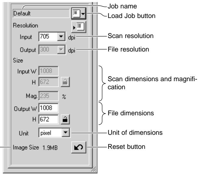
Inputting scan settings manually
Settings for the final scan can be made in the index scan or prescan windows.
Input-resolution list box:
values can be selected among the drop-down list or be entered into the box directly. See scanner resolution in the scanner notes section of the hardware manual for the resolution of the specific scanner model.
Output-resolution list box:
values can be selected among the drop-down list or be entered into the box directly. Output-resolution cannot be entered if pixel is selected in the unit list box.
Input-size text box:
input size is determined by either the cropping frame dimensions or the values entered in the width and height boxes. The cropping frame will adjust to any value entered. Input-size cannot be entered if pixel is selected in the unit list box.
Input-size lock button:
to lock the input values. The cropping frame can be moved, but not resized while this button is clicked. Clicking the button again releases the lock. The input-size lock button cannot be used if pixel is selected in the unit list box.
Magnification text box:
to set image magnification. This value is based on input and output resolution, or output and input size. The magnification text box cannot be used if pixel is selected in the unit list box.
When the input size and output size are unlocked, the input resolution and output size vary according to the entered magnification value. When the output size is locked, the input resolution and input size vary according to the entered magnification value. When the input size is locked, the input resolution and output size vary according to the entered magnification.
Output-size text box:
output size is determined by either the cropping frame dimensions or the values entered in the width and height boxes. The width and height of the output image can be directly entered into the text boxes; the input resolution, input size, and cropping frame adjust according to the entered dimensions.
Output-size lock button:
to lock the output size values.
Unit list box:
the input and output size unit can be changed: pixels, millimeters, centimeters, inches, pica, and points.
Image size display:
size based on the total number of pixels in the image and can be different from the size of the saved data depending on the file format selected.
Reset button:
to initialize all current settings.
About resolution and output size
Resolution can be expressed in dpi (dots per inch). This refers to how many pixels are placed along one linear inch. A resolution of 350 dpi, which is commonly used in commercial printing, means that an area of one square inch would use 122,500 pixels. The larger the resolution, the greater the detail in the image. However, as the resolution increases, so does the file size.
The image resolution depends on the resolution of the output device. A printer with a resolution of 150 dpi will not be able to print a 300 dpi file any better than a 150 dpi file; the 300 dpi file will just be four-times larger. Once the output resolution is determined, the input resolution can be calculated from the magnification needed to match the output.
$$ \begin{array}{l l l} \frac {\text {I n p u t r e s o l u t i o n}}{\text {O u t p u t r e s o l u t i o n}} & = & \frac {\text {O u t p u t s i z e}}{\text {I n p u t s i z e}} = \quad \text {M a g n i f i c a t i o n f a c t o r} \end{array} $$
For example, to make a 144mm× 96mm print at a resolution of 150 dpi from 35mm film (image size: 36mm× 24mm ), the magnification can be calculated by dividing the print dimensions by the film dimensions: 96mm / 24mm = 4 times. The input resolution can then be determined from the magnification factor: 150dpi× 4 = 600dpi .
When scanning an image to be displayed on a monitor, the only important factors are the pixel dimensions of the file and monitor. Although printers can print files with different resolutions at a given size, monitors cannot add or remove pixels to fit the display area. The image in the example above has a pixel dimension of 850 X 566, too large for a 800 X 600 pixel 15-inch monitor.
Scan setting examples
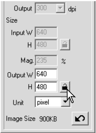
Example 1: setting the scanner output by pixels. This example creates an image with the pixel dimension of 640 × 480 to be displayed on a monitor.
Select pixel from the unit list box. The output-resolution and input-size boxes are deselected.
Enter the dpi resolution for the output size; 640 for the width and 480 for the height. Click the output-size lock button to fix the values; the output-size boxes will be deselected.
Use the mouse to adjust the cropping frame over the prescan image to define the final scanning area. Click on the frame of the cropping area to resize the box. The input resolution will adjust according to the cropping area. Click and drag the center of the area to move the frame.
The scan settings are complete and the final scan can be made (p. 20). Once made, scan settings remain in effect until changed.
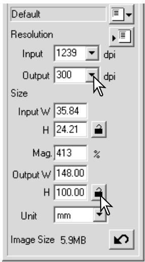
Example 2: setting output by print size and output resolution. This example creates a 148mm X 100mm image to be printed on a 300 dpi printer.
Select millimeters from the unit list box.
Enter the output resolution of the printer in the output-resolution list box: 300.
Enter the output size; 148 for the width and 100 for the height. Click on the output-size lock button to fix the values.
Use the mouse to adjust the cropping frame over the prescan image to define the final scanning area. Click on the frame of the cropping area to resize the box; the input resolution will adjust according to the cropping area. Click and drag the center of the area to move the frame.
The scan settings are complete and the final scan can be made (p. 20). Once made, scan settings remain in effect until changed.
Saving scan settings as a Job
Frequently used scan settings can be saved.
With the settings to be saved in the scan setting window, click the save Job button. The Job-registry dialog box will open.
Select the category in which to save the settings from the drop-down menu.
Enter the Job name. Click OK to save the settings. The Job file name can contain up to 24 characters. See page 20 to load a Job.
Deleting a Job
A Job file can be deleted. Once deleted, it can not be recovered.
Click the load Job button.
Select the Job file to be deleted from the Job categories in the selection window. Use the following key(s) to delete the selected file:
| Windows | Delete key |
| Macintosh | Command key + D |
Click the cancel button to close the window.


ADVANCED IMAGE PROCESSING
More image-processing tools
This section covers the advanced image-processing tools in the DiMAGE Scan Utility as well as functions to view and save image corrections. The basic image-processing section on pages 22 through 29 should be read before continuing.
The functions available vary between scanner model.

Digital ICE (p. 24)

Digital ROC (p. 45)

Digital GEM (p. 46)

Pixel Polish (p. 23)
Grain Dissolver (p. 29)
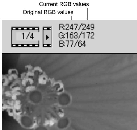
The RGB display will show the color values for any point on the image; the first numbers of each color channel indicate the original value of the pres-canned image followed by the current value with any changes made through processing. Simply place the mouse pointer on the image area to see the RGB values of that point. Pressing the shift key (Windows) or command key (Macintosh) will display the CMY values.
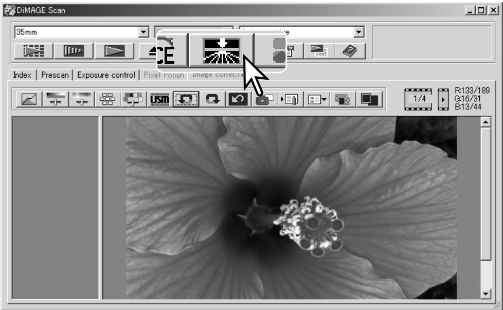
Digital ROC - Reconstruction Of Color
Digital ROC (Reconstruction of Color) can restore the faded color of old film, see page 2. The results with Digital ROC vary with the condition of the film.
Original image
After Digital ROC processing
Click the Digital-ROC button to activate the function; the current prescan image will be deleted. Press the prescan button to view the results.
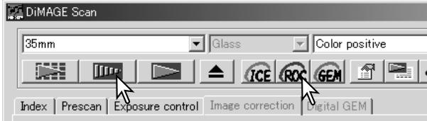
When Digital ROC is used, the prescan also makes the final scan. When the final scan is made, the image data is simply processed and saved. While the final scan is relatively fast, the prescans require more time. Because the final scan and prescan are made at the same time, always preform the prescan with the autofocus-at-scan function active in the preferences box (p. 30), or with point AF (p. 36) or manual focus (p. 37). To turn off Digital ROC, click the Digital-ROC button again.
Digital ROC cannot be used with 16-bit linear color depth (p. 30). When Digital ROC is activated, the auto-expose-for-slides setting in the preferences box, color matching, and the AE lock and AE-area-selection functions are disabled.
Digital ROC cannot be used with traditional silver-halide black and white films. Special black and white films that are designed to be developed in a C-41 or equivalent color process, Kodak Select Black & White 400, Kodak T400CN, or Ilford XP2 Super, can be processed with the Digital ROC function. These films should be scanned with the color-negative film-type setting. Results cannot be guaranteed with other types of black and white film.
The undo, redo, and reset-all buttons have no effect with the Digital ICE3 functions.
Digital GEM - Grain Equalization & Management
Digital GEM reduces the effect of grain in color film. Grain is a sandy texture that can sometimes be seen in smooth uniform areas of the image such as the sky. Grain is more pronounced in fast film. The results with Digital GEM vary with the film.
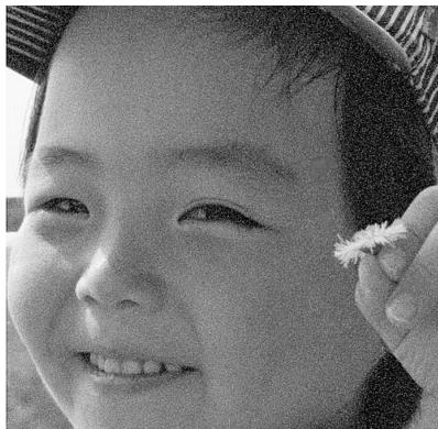
Original image

After Digital GEM processing
Digital GEM cannot be used with traditional silver-halide black and white films. Special black and white films that are designed to be developed in a C-41 or equivalent color process, Kodak Select Black & White 400, Kodak T400CN, or Ilford XP2 Super, can be processed with the Digital ROC function. These films should be scanned with the color-negative film-type setting. Results cannot be guaranteed with other types of black and white film.
Click the Digital-GEM button in the main window; the Digital-GEM tab is activated. Each time the Digital GEM button is pressed, the prescan image is deleted.
Make a prescan of the image to be processed.
When Digital GEM is used, the prescan also makes the final scan. When the final scan is made, the image data is simply processed and saved. While the final scan is relatively fast, the prescans require more time. Because the final scan and prescan are made at the same time, always preform the prescan with the autofocus-at-scan function active in the preferences box (p. 30), or with point AF or manual focus.
Set the input resolution of the image in the scan-setting window with a Job (p 20) or by manually inputting the value (p. 40). The effect of image grain is related to the input resolution.
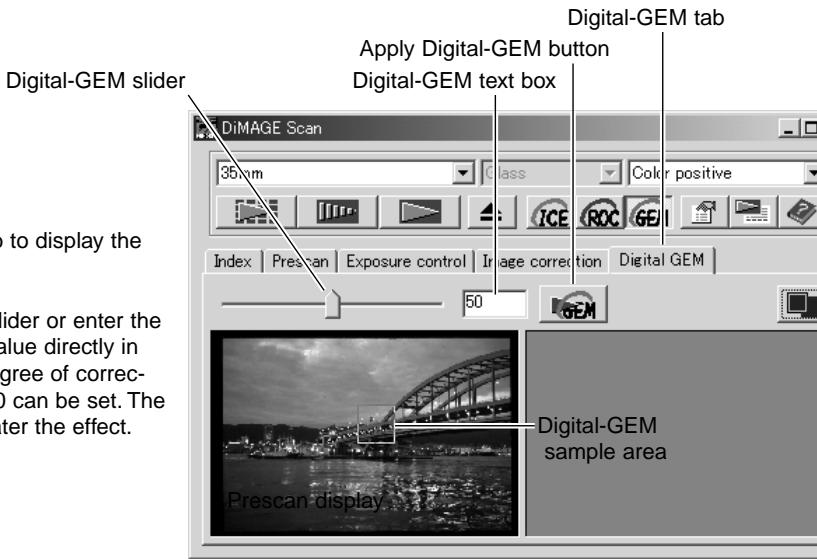
Click the Digital-GEM tab to display the Digital-GEM window.
Adjust the Digital-GEM slider or enter the Digital-GEM correction value directly in the text box to set the degree of correction. Values from 0 to 100 can be set. The larger the value, the greater the effect.
Adjust or move the Digital-GEM sample area to select the portion of the image to be used to evaluate the Digital-GEM correction. Choose a smooth uniform area for the evaluation; skin or sky are good subjects. Using the mouse, place the pointer on the sample area frame; the pointer will change to a double arrow. Simply click and drag the edge of the frame to adjust the area; the maximum size of the sample area depends on input resolution. By placing the pointer in the center of the frame, the pointer will changed to a four-pointed arrow. Simply click and drag to move the frame. With the pointer outside the frame, click and drag to define a new sample area. To extend the area over the entire image, press the control key (Windows) or command key (Macintosh) and the A key at the same time.
Click the apply Digital-GEM button to preview the Digital-GEM effect on the sample area. Every time the Digital-GEM sample area is changed, or the degree of correction is adjusted, the apply button must be used Digital-GEM button to view the results. The sample image can be magnified by clicking the fit-to-window button.
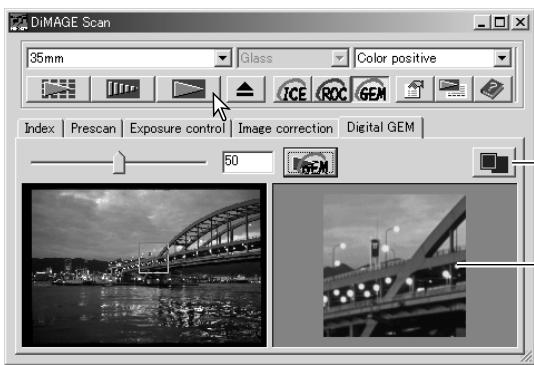
Click the scan button to save the final image. To turn off Digital GEM, click the Digital-GEM button again.
Fit-to-window button
Digital-GEM sample display
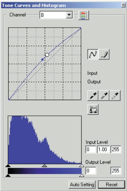
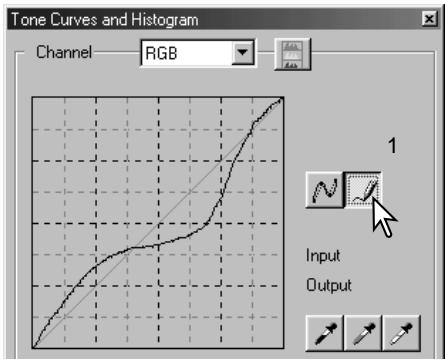
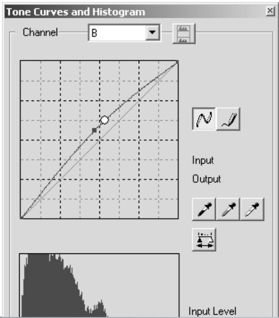
Tone curve and histogram palette
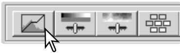
Click the tone-curve/histogram button to display the palette.
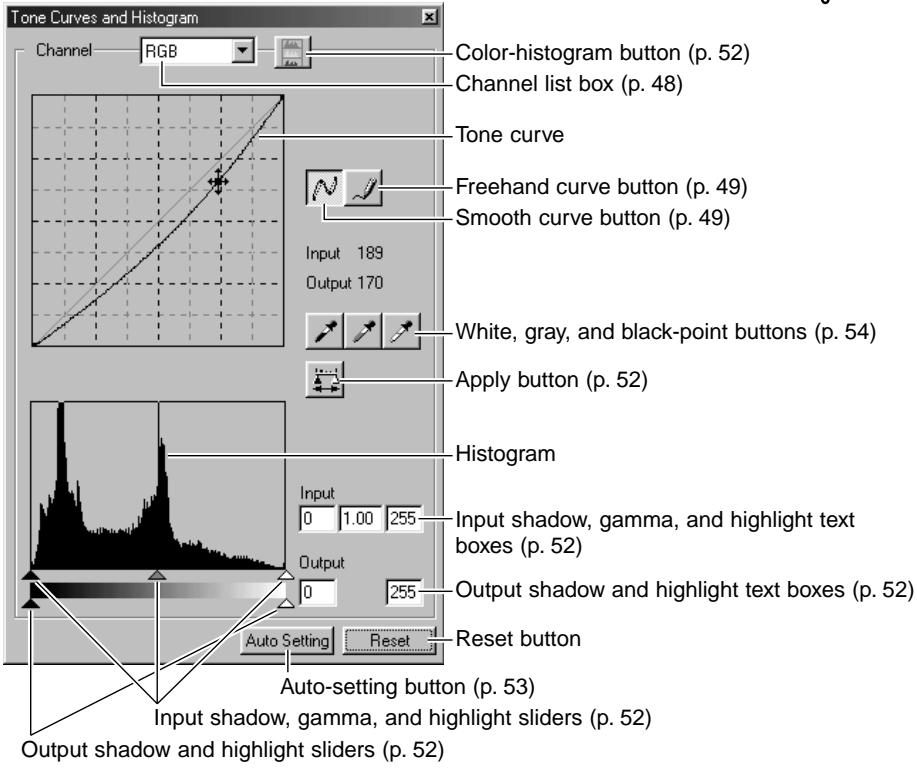
Using tone curves
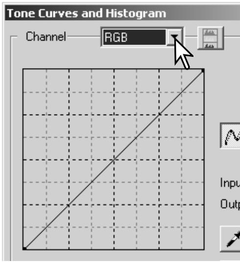
Click the arrow next to the channel box to select the channel from the drop-down menu.
To make adjustments to the color balance of the image, select the appropriate color channel. To adjust the contrast or brightness of the image without affecting the color, select the RGB channel.
The tone curves can be displayed with keyboard shortcuts. While holding the control key (Windows) or command key (Macintosh), press 0 (zero) to display the RGB channel, 1 to display the red channel, 2 to display the green channel, or 3 to display the blue channel.
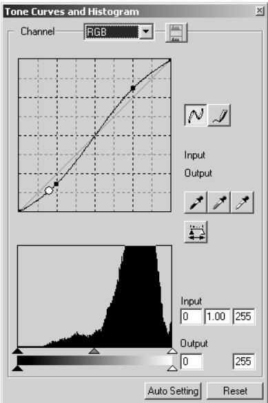
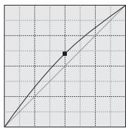
Place the mouse pointer over the tone curve. Click and drag the curve. Any corrections made on the tone curve are immediately applied to the displayed image.
Each time the tone curve is clicked, a node is attached to the curve. The nodes can be moved by clicking and dragging. The horizontal axis (input level) represents the brightness levels of the original image, and the vertical axis (output level) the change applied to the image.
By placing the mouse pointer on the display image, the grey or color level of that point will be indicated on the tone curve by a white circle.
The reset button cancels all corrections in all channels.
Drawing tone curves by freehand
Click the freehand-curve button (1). The mouse pointer changes to the pencil tool when placed on the tone curve.
Click and drag the pointer to draw a new curve. Extreme image manipulations are possible with the freehand curve tool.
To smooth a rough freehand curve, click the smooth-curve button (2). Nodes will be automatically placed on the curve and can be adjusted with the mouse.
With extreme freehand curves, the smooth curve button may significantly change the shape of the curve. Press the undo button to return to the original freehand curve.

A short guide to tone curve corrections
Image processing is a highly specialized and difficult field that takes years of practice to master. This basic guide to using tone curves covers a few simple procedures to improve your pictures. For more about digital-image processing, consult your local book dealer about self-help guides on this subject.
About the tone curve
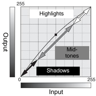
The tone curve is a graphic representation of the brightness and color levels of the image. The bottom axis is the 256 levels of the original image (input data) from black to white. The vertical axis is the corrected image (output data) with the same scale from top to bottom.
The bottom left portion of the graph represents the dark colors and shadow areas of the image. The middle section represents the mid-tones: skin, grass, blue sky. The top right section is the highlights: clouds, lights. Changing the tone curve can affect the brightness, contrast, and color of the image.
Bring out detail in the shadows
This is a simple technique to make a subject hidden in the shadows brighter. Unlike the brightness level control (p. 26), this method of correction will not lose details in the highlight areas of the image.
With the RGB channel selected, place the smooth-curve cursor on the center of the curve. Click and drag the curve up. Look at the displayed image to judge the result. The adjustment can be very small and still have a significant impact on the image. Moving the tone curve down will make the image darker.
Increasing image contrast
The contrast of an image can be changed. The light blue 45^ line on the tone-curve graph represents the original contrast of the image. Making the angle of the tone curve greater than 45^ will increase the contrast. Making the angle less than 45^ will reduce the contrast.
With the RGB channel selected, click on the tone curve near the top and bottom to add two nodes. Slightly move the top node up and the bottom node down. This will increase the angle of the central portion of the tone curve and increase the contrast of the image without making an overall change in image brightness.
Correcting color
By selecting individual color channels on the tone curve, adjustments to the overall color of an image can be made. This can be used to eliminate unnatural color casts or add warmth to a picture.
If the image is too red, green, or blue, simply drag the corresponding color-channel curve down until the color appears natural. If the color cast is predominantly one of the secondary colors, cyan, magenta, or yellow, move the curve of the complementary color up. For example, if the image is too yellow, move the blue curve up, see the color example on page 2. For more on complementary colors, see page 27.
Histogram corrections
The histogram indicates the distribution of pixels with specific brightness or color values in the image. Using the histogram can maximize the output of the image data. Changes made with the histogram are also displayed on the tone curve.
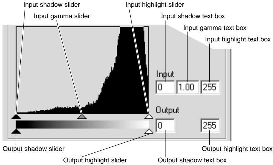
The color histograms can be displayed with the channel list box or with keyboard shortcuts. While holding the control key (Windows) or command key (Macintosh), press 0 (zero) to display the RGB channel, 1 to display the red channel, 2 to display the green channel, or 3 to display the blue channel.
The histogram can be used to maximize the distribution of the pixels in the image. The highlight level, shadow level, and gamma can be set manually with the sliders or text boxes.
The gamma slider defines the mid-tones of the image. Dragging the gamma slider to the right will darken the image, and dragging it to the left will brighten it. Similar to the tone-curve correction described on page 50, the gamma slider allows the brightness of the image to be adjusted without loosing image information.
The input highlight slider sets the white level. As the slider is moved to the left, an apparent increase in contrast can be seen in the displayed image. All pixels to the right of the slider are set to 255 and any image detail they may contain will be lost. This can be an important tool for improving copy images of text on a white background. Uneven illumination, or faded or stained paper can be distracting when copying text or line art. By adjusting the white level, the imperfections of the white background can be eliminated leaving only the darker text visible.
The input shadow slider sets the black level. As the slider is moved to the right, an apparent increase in contrast can be seen in the displayed image. All pixels to the left of the slider are set to 0 and any image detail they may contain will be lost.
The black and white output levels can be adjusted. By moving the output highlight and shadow sliders, the contrast of the image can be reduced.
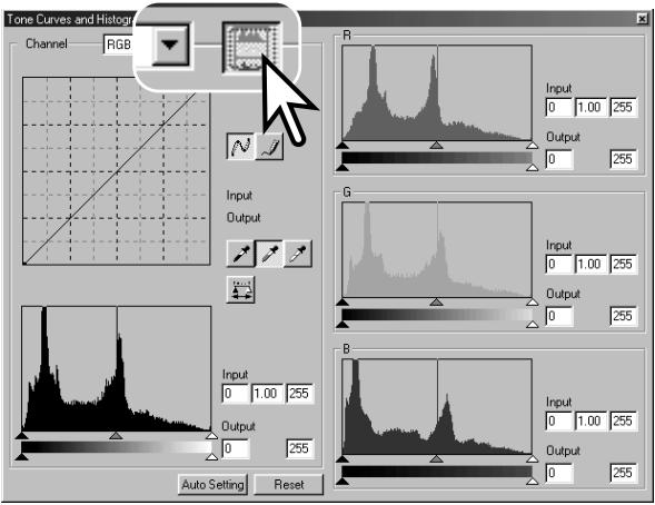
Click the color-histogram button to view the red, green, and blue histograms.
Click the histogram RGB display button again to close the color histogram display.
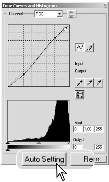
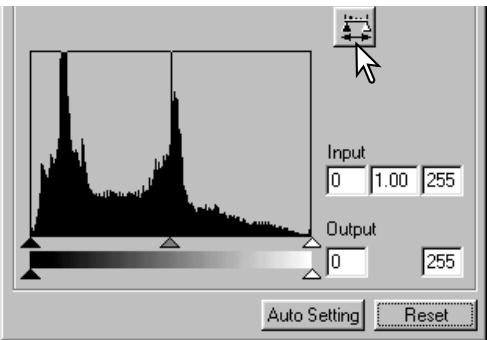
Tone curve / histogram auto setting
The auto-setting function automatically adjusts the tone curve and histogram to maximize image contrast and color. The darkest pixels in the image are set to a black level of 0, the brightest pixels are set to a white level of 255, and the rest of the pixels are distributed between them equally.
Click the auto-setting button. The change is immediately reflected in the displayed image. To view the change in the histogram, press the apply button. Click the reset button to cancel the auto setting.
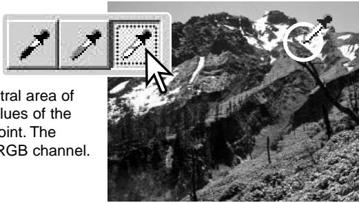
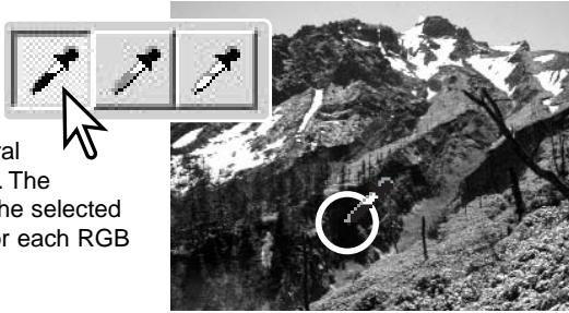
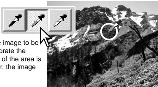
White, gray, and black point corrections
On the tone curve / histogram palette, corrections can be made by specifying a white, black, and gray point within the image. Locating an appropriate neutral area within the image is critical to correctly calibrate the software. When the dropper tool is selected, the RGB display is active and can be used to evaluate the image area. All changes are immediately reflected in the display image.
Click the white-point button; the mouse pointer changes to the white dropper tool.
With the dropper tool, click on the brightest neutral area of the image to define it as the white point. The values of the image will be adjusted based on the selected point. The default level for the white point is 255 for each RGB channel.
Click the black-point button.
With the dropper tool, click on the darkest neutral area of the image to define it as the black point. The values of the image will be adjusted based on the selected point. The default level for the black point is 0 for each RGB channel.
Click the gray-point button. The grey point controls the color of the image.
With the dropper tool, click a neutral area of the image to be defined as the gray point. The area used to calibrate the gray point must be neutral. The brightness level of the area is not important, but if the area has a definite color, the image will not be color balanced correctly.
Click and hold the apply button to show the change on the histogram. Click the reset button to cancel all corrections.
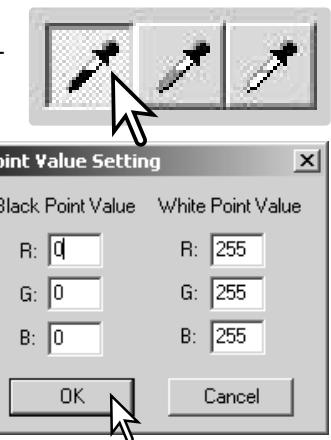
Setting the white and black-point values
The white and black-point values are set to 255 and 0 for each RGB level. Changing these values allow the calibration of an image with no true white or black.
Double-click on either the white-point or black-point button to activate the point-value-setting dialog box.
Enter the new white-point or black-point values. Click OK.
With the point-value-setting dialog box open, the mouse pointer can be used to measure the color of any point on the displayed image. The RGB display shows the original values for the image on the left and the current values for the image on the right.
Calibrate the image as described in the white, black, and gray point corrections section.
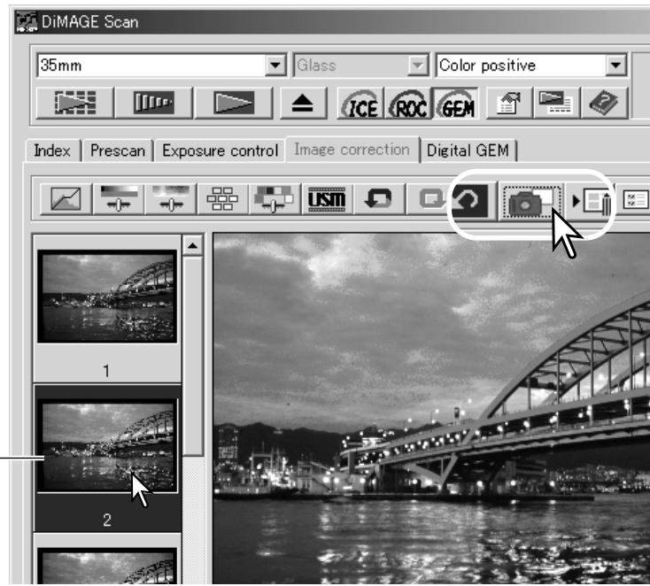
Tracking image corrections - Snapshot button
Image corrections can be stored temporarily as a thumbnail next to the displayed image. Simply click the snapshot button on the tool bar to create a thumbnail with the current image corrections.
To return to a previous image correction, click on the corresponding snapshot thumbnail. The thumbnail image will replace the displayed image. The number of snapshots that can be made is only limited by the computer memory. To delete a snapshot, click on the thumbnail and press the keyboard delete key.
Snapshot display area
Hue, saturation, and lightness palette
This palette adjusts the image in reference to the HSB color model. These controls can be used to manipulate the color image rather than producing a realistic representation.
The HSB color model defines color based upon human perception rather than photographic processes. Hue refers to each separate color in the model. Saturation is how vivid each colors is. Lightness describes how bright or dark a color is in the color space.
The hue control is not a color balancing tool. It is a creative tool. When changing hue in the palette, each color is assigned a new hue depending on the degree of rotation through the color space. For example, a very simple color space could have three colors: red, green, and blue. I have a red barn next to a green tree with a blue sky. Now I rotate the image in the color space; the colors are reassigned a new hue based on the position - the barn is green, the tree is blue, and the sky is red. The HSB color space is similar, but with many more hues; see the color example on page 75.
Unlike the brightness control in the brightness, contrast, color balance palette, the lightness control does not change the apparent density of the colors equally. For example, with an extreme increase in lightness, blue will not appear as light as yellow.
Click the hue, saturation, and lightness button to open the palette.
Drag the hue, saturation, or lightness slider, or enter specific values in the corresponding text box to make corrections; changes will be reflected in the display image. Dragging each slider to the right or inputting a positive number in the text box increases the saturation, and lightness. The hue slider rotates the colors in the image through the color space; the maximum position to the right (180^) is the same as the maximum position to the left (-180^) . Click the reset button to cancel any changes.
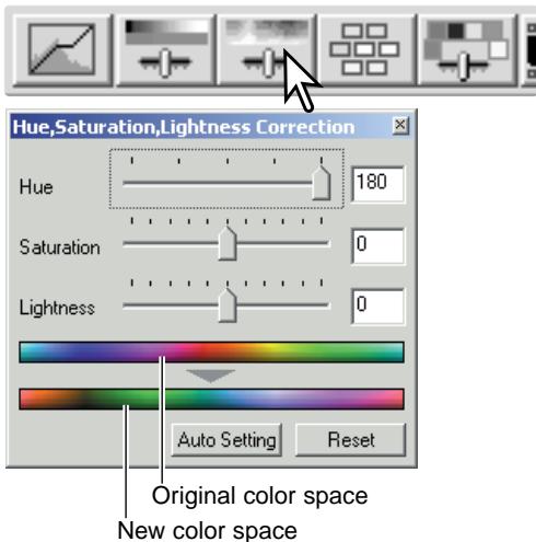
Two color samples are displayed at the bottom of the palette. The top bar indicates the color space of the original image. The bottom bar displays the relative changes to the color space.
Clicking the auto-setting button adjusts the saturation automatically without affecting the hue or lightness. Click the reset button to cancel any changes.
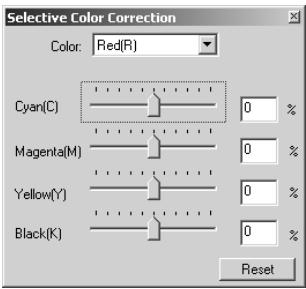
Selective-color palette
Selective-color correction is an advanced technique to refine the colors in the image. A cyan, magenta, yellow, and black channel can be used to adjust the six separate color groups in the image: red, green, blue, cyan, magenta, and yellow. The black-level slider controls the brightness of the selected color group. This type of correction is effective in changing a specific color without influencing any of the other colors in the image. For example, if the sky looks purplish instead of blue, magenta can be reduced in the blue color group. See page 75 for a selective-color example.
Click the selective-color button to open the palette.
Select the color group to be corrected from the drop-down menu at the top of the window.
Drag a slider or enter a value in a text box to adjust the selected color group. More than one slider can be used to adjust the selected color. Changes will be reflected in the display image. Click the reset button to cancel any changes.
About RGB and CMY
The RGB color model is an additive process that uses the primary colors of light: red, green, and blue. An additive color system mixes the three colors to recreate the entire spectrum of light. If all three colors are mixed, white light is produced. Television sets and computer monitors use RGB to create images.
The CMY color model is a subtractive process that uses the secondary colors: cyan, magenta, and yellow. A subtractive color system recreates color with pigments and dyes to absorb unwanted color. If all three colors are mixed, black is produced. Film-based photography is a subtractive process. Printing technology is also a subtractive process, but, unlike photographic systems, it requires a black channel (K). Because of the imperfections of printing inks, cyan, magenta, and yellow cannot produce a true black when mixed, printers use what is called a four-color process (CMYK) to reproduce images.
Unsharp mask
The unsharp mask sharpens edges in the image without affecting overall image contrast. This mask can be used with soft or slightly out-of-focus images. The effect of the unsharp mask is very subtle, but makes a significant improvement to the overall appearance of the image.
Click the unsharp-mask button to open the unsharp-mask dialog box.
Drag the sliders or enter values in the text boxes to adjust the parameters of the mask. The full effect of the unsharp mask cannot be evaluated in the pre-scan image. It can only be judged in the final scan.
The result of the unsharp mask differs with image resolution. Make several scans with slight changes to the output resolution until the intended result is produced. Clicking the reset button restores the default settings.
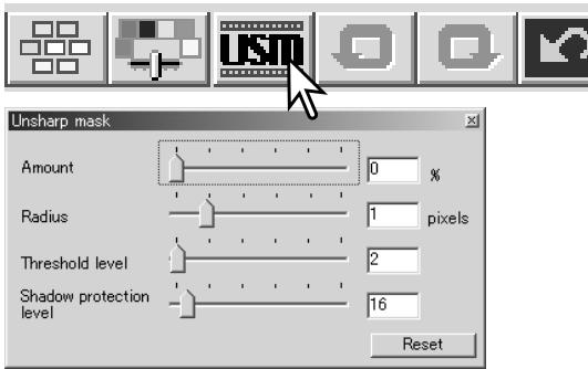
Amount: to adjust the contrast of the mask between 0% and 500% . If the value is too high, pixilation will be apparent; the image becomes noticeably rough or grainy. 150% to 200% is recommended for high-quality printed images.
Radius: to increase the edge sharpness of the pixels. The radius can be adjusted between 0.1 and 5. The default setting is 1. Changes to the radius are more apparent on printed images than images displayed on a monitor. A level of 1 to 2 is recommended for high-quality printed images.
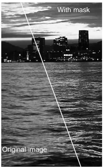
Threshold level: adjusted in integers between 0 and 255. The default setting is 2. If the difference between the surrounding pixels is greater than the threshold level, that pixel is recognized as a sharp subject pixel. When the level is set to 0, the whole image is corrected. The threshold level can separate smooth or even areas from edges and detailed areas to be sharpened.
Shadow protection level: to limit the sharp subject pixels in the shadows. The level can be adjusted in integers between 0 and 255. The default setting is 16. When the luminance level is greater than the shadow protection level, that pixel is recognized as a sharp pixel.
Saving image corrections
All corrections applied to an image can be saved as an image-correction Job. The Job can be loaded into the utility at any time and applied to different images. This is a time-saving function when a large number of images need too be processed with the same correction settings.
Click the save image-correction Job button to save the current image-correction settings.
Enter the Job name. Click OK to save the settings.
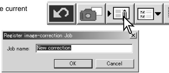
Loading image-correction Jobs
Display the image to be corrected in the image-correction tab. Click the load image-correction Job button to load a saved image-correction settings.
Click on an image-correction Job thumbnail to select it. Click OK to apply the Job to the displayed image. Jobs are loaded into the snapshot display area. Multiple Jobs can be loaded.
To delete a Job, open the load window and highlight the Job to be deleted. Press the keyboard delete button to erase the file.
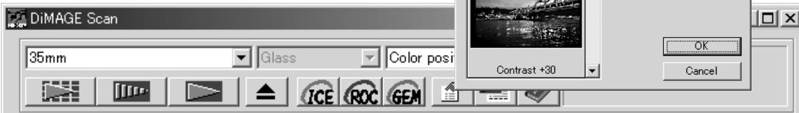
Index Prescan Exposure control Image correction Digital GEM

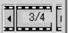
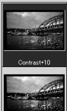
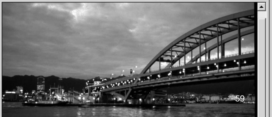
CUSTOM WIZARD
The Custom Wizard is an automated scanning routine. Screens vary with scanner model.
Insert a film holder into the scanner. Click the Custom Wizard button.
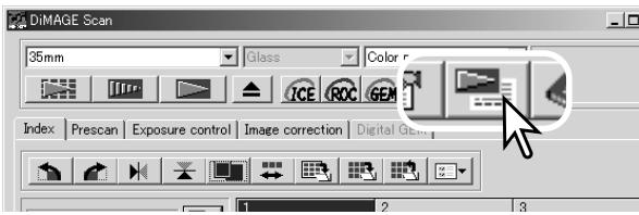
On the Custom-Wizard-setting dialog box, select New from the Custom Wizard settings. Click the next button.
If previous Custom Wizard settings have been saved, they will be displayed in this window. To use any settings, simply select it with the mouse. The delete button erases the selected setting.
The film dialog box will vary with scanner model. Set up the dialog box for the film and holder in use. Select the frame number(s) of the images to be scanned. The frame number refers to the frame number of the holder or, in the case of the optional APS adapter, the film frame numbers.
Click the next button to continue.
Select scanning preferences in the dialog box. Click the next button to continue.
For information on the preference settings, see page 30. For information on color matching, refer to page 66.
Enter scan settings. Click the next button to continue.
See pages 20 and 40 for details on Jobs and manual scan settings. See page 19 for information on auto-cropping. The auto-cropping function will take priority over any scan settings entered.
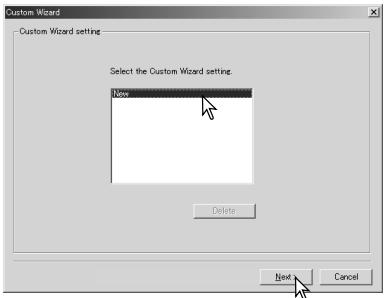
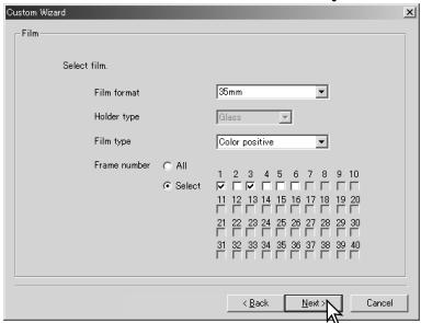
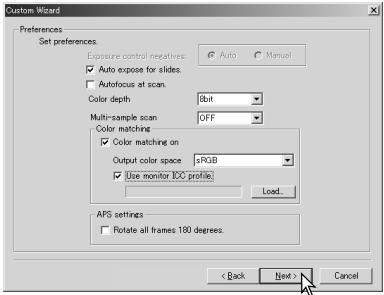
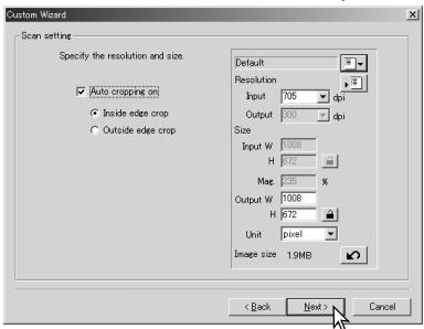
Select specific image processing. Functions available vary between scanner model. Click the next button to continue.
Digital ICE (p. 24), ROC (p. 45), GEM (p. 46), and Pixel
Polish (p. 23) cannot be used with black and white film. Digital ICE cannot be used with Kodachrome. When using Digital GEM, the amount of correction must be set. The Grain Dissolver automatically activates with Digital ICE when both functions are available.
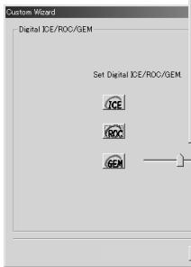
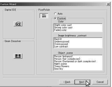
Make any adjustments to the scanner exposure. Previously saved settings can be loaded. See page 32 for more information. Click the next button to continue.
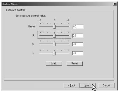
Select image-correction settings. Click the next button to continue.
Image corrections can be made by loading an image-correction Job (p. 59). The auto-setting functions make automatic corrections: the tone curve and histogram setting improves color and contrast: the brightness, contrast, and color-balance setting improves contrast and brightness: the hue, saturation, and lightness setting improves saturation.
Click the save button to save the Custom Wizard settings. Enter the file name in the save window and click OK. The next time the Custom Wizard is used, those settings can be selected in the Custom Wizard setting dialog box.
Click the start button to begin automatic scanning. When scanning multiple images, a serial number is added automatically.
BATCH SCAN UTILITY
The Batch Scan Utility is for scanning a large volume of images. This utility automatically scans, processes, and saves all the images in a film holder. The Batch Scan Utility is opened with the DiIMAGE Scan launcher. This software is not available with all scanner models, see the scanner notes section in the scanner hardware manual.
When the Batch Scan Utility button in the launcher window is clicked, the scanner will initialize. When the set-holder message appears, insert the holder into the scanner; all the frames in the holder will be scanned and saved, and the holder will be ejected automatically. To scan another batch, change the film in the holder and reinsert it into the scanner. Click the Batch Scan Utility button to begin scanning. The scanner only initializes before the first holder is scanned.
To change or confirm the Batch Scan settings, click the settings button.
Batch scan settings
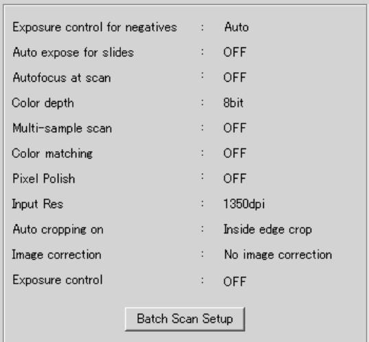
File destination:
D:My DocumentsMy Pictures


File Name:
Name files automatically
Name files manually
ScanImage
Batch Scan Setup
Cancel
OK
Film type: Color negative
The film type is selected with the drop-down menu. When making Batch Scans, different film types cannot be mixed.
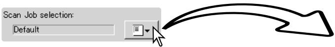
The output size and resolution can be specified using a Job. Click the Job load button to open the Job selection dialog box. For more on Jobs, see page 20.
Jobs can be created or one-time custom settings can be made using the Batch Scan setup dialog box, see below.
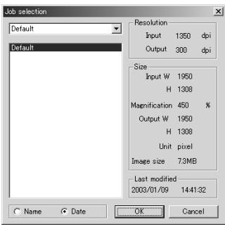
ICE
To select automatic image processing, click the appropriate buttons. The functions available differ between scanner models, see page 22. The Grain Dissolver automatically activates with Digital ICE when both functions are available.
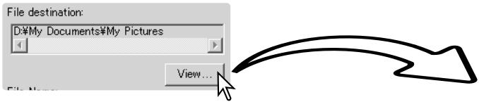
To select the destination of the scanned images. Click the view button to open the file-destination dialog box. Use the folder tree to locate the folder in which to save the files. Click the folder to select it. Click the OK button to complete the operation. The destination will be displayed in the setting window.
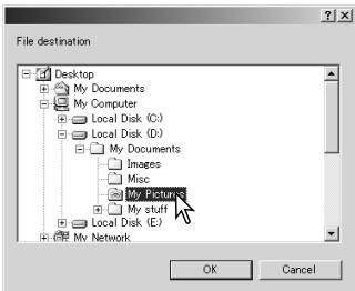
File Name:
Name files automatically
Name files manually
ScanImage
To select file names. The automatic option names files based on the date and time of the scan; the file name begins with DS followed sets of two registers to indicate the year, month, day, hour, minute, and second. DS030523134510 was scanned in 2003 on May 23rd at 1:45pm and 10 seconds. The hour registers are
based on a 24hr clock. The manual option uses the name entered in the text box plus a four digit serial number which is automatically added.

To change the scanner setup listed in the window. See the following page.

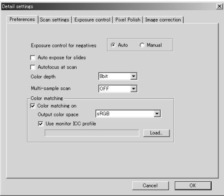
To change scanner preferences.
For more on the preferences dialog box, see page 30. For information on color matching, see page 66.
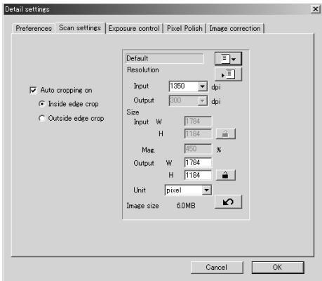
To crop the image automatically and to set the output size and resolution.
See page 19 for information on auto cropping. See page 43 on how to make and save scan settings.
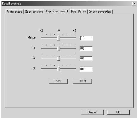
To control the scanner exposure.
See page 32 on how to make and save exposure settings.
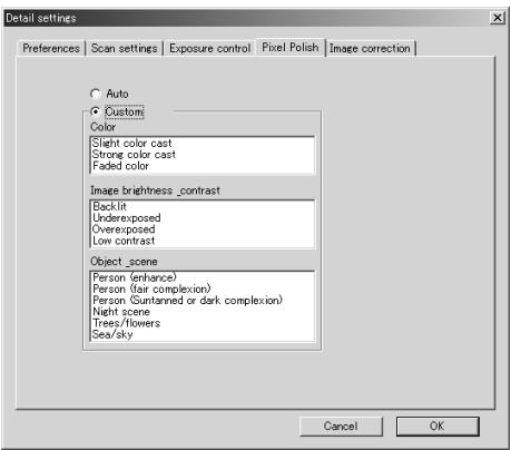
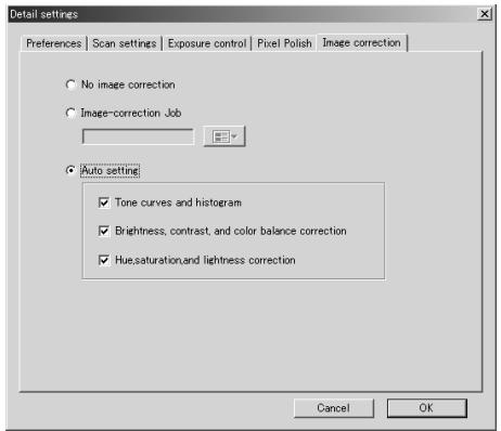
To apply Pixel Polish. See page 23.
To apply image processing to the scanned images.
See page 59 on image-correction Jobs.
The auto-setting functions automatically correct the scanned image: the tone curve and histogram setting improves color and contrast: the brightness, contrast, and color-balance setting improves contrast and brightness: the hue, saturation, and lightness setting improves saturation.
COLOR MATCHING
Each output device (monitor or printer) defines color and contrast differently. To ensure the reproduction of the image on the monitor matches the reproduction of the image from the printer, the color space for both devices must be defined. Color matching is activated in the preferences box. Color matching increases the scanning time.
The DiIMAGE Scan color matching function matches the scanned color with specified color spaces. The color matching system can use the monitor's ICC profile to display the image as accurately as possible.
Click the preferences button to access the color-matching function.
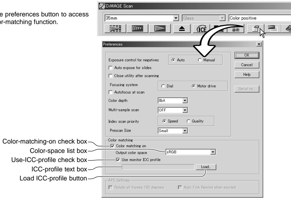
Setting the output color space
Click the color-matching-on check box.
Select the output color space from the color-space drop-down menu. See the following page for descriptions of the color spaces.
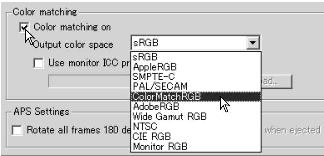
Output color spaces
The choice of output color space depends on how the image will be reproduced. For most personal use where the image is displayed on a monitor or printed with a small printer, sRGB color space is adequate. Other color spaces have been included for professional and technical applications. For recommendations for color space use, see page 69.
| sRGB | This color space reflects the average PC monitor characteristics, and is considered the standard for multi-media and Internet usage. sRGB is not suitable for professional prepress applications because of its narrow reproduction range. |
| Apple RGB | Widely used in DTP and is the standard color space in many common graphic arts and design applications: Adobe Illustrator, Photoshop, etc. |
| SMPTE-C | The current television broadcasting standard used in the United States. |
| PAL/SECAM | The current television broadcasting standard used in Europe. |
| ColorMatch RGB | This standard has a wide gamut and is ideal for use with Radius Press View monitors, which are commonly used in prepress production. |
| Adobe RGB | This color space is wider than ColorMatch RGB. The extensive color range makes it ideal for prepress use. However, the range is so great that it includes many colors that cannot be printed with a four-color printing process. |
| Wide-gamut RGB | Utilizing the color coordinates of the spectrum, this standard offers an extreme range of colors. However, most of the colors that can be generated cannot be reproduced on standard computer monitors or by printing technology. |
| NTSC | The current television broadcasting standard used in Japan. |
| CIE RGB | This color space is defined by the CIE (Commission Internationale d'Eclairage). |
| Monitor RGB | This color space is defined by the monitor's ICC profile. See setting the monitor ICC profile section on page 68. |
Setting the monitor ICC profile
The ICC profile for a specific monitor can be specified in the color-matching section of the Preferences dialog box. Refer to the monitor instruction manual for the profile name.
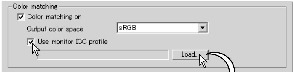
Click the use-monitor-ICC-profile check box.
Click the load ICC-profile button. The operating system's file-open dialog box will open.
Locate and open the ICC profile for the monitor in use. The selected profile will be displayed in the preferences window. Click OK in the preferences window to set the ICC profile.
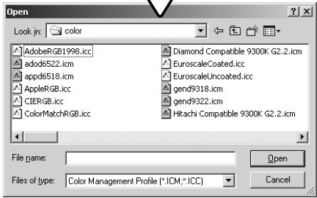
Monitor ICC profiles are located in the same folder as the scanner color profiles, see below. When using Mac OS X, the monitor profiles are in the following location: [Library] -> [ColorSync] -> [Profiles] -> [Displays].
Scanner color profiles
When installing the DiIMAGE Scan Utility software, scanner color profiles will be automatically installed. These profiles have been included for advanced color matching with profile-to-profile conversions in sophisticated image-processing or DTP applications. Refer to the scanner notes section of the hardware manual for the profile for a specific scanner model.
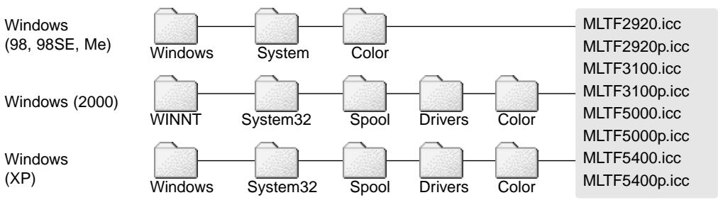
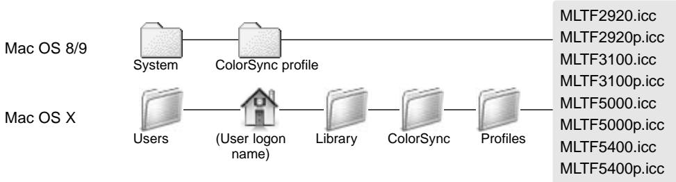
Color matching recommendations
The following are recommendations for output color space and monitor ICC-profile settings with image-processing applications. Some applications, such as Adobe Photoshop 5 or later, have a monitor correction display function which automatically corrects the monitor display to a specific color space.
Output Color Space: select the same color space as set in the application. With Photoshop 5.0 or later, look in the color-setting option in the file menu for the profile setup window.
ICC Profile: Use the profile for the monitor in use.
When using an application without a monitor correction display function such as Photoshop Elements, or when the function is disabled:
Output Color Space: Monitor RGB
ICC Profile: Use the profile for the monitor in use.
The ICC profile for a specific monitor should be available from the manufacturer. These may be downloaded from the manufacturer's web site. See the monitor's instruction manual on how to install the ICC profile.
Color monitor ICC profiles can be created with one of the profile creation tools on the market. They can also be created with the monitor-adjustment-assistant function installed in a Macintosh operating system, or with Adobe gamma included in Adobe Photoshop 5 or later for Windows.
APPENDIX
Using multiple scanners
When multiple scanners are connected to the same computer, the select-scanner window will open when the DiIMAGE Scan Utility is launched. Select the scanner to be used from the list and click OK to continue.
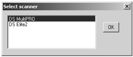
If the scanners are the same model, the select-scan-
ner window will not open. The computer will use the first scanner detected during startup.
Uninstalling the DiIMAGE Scan Software
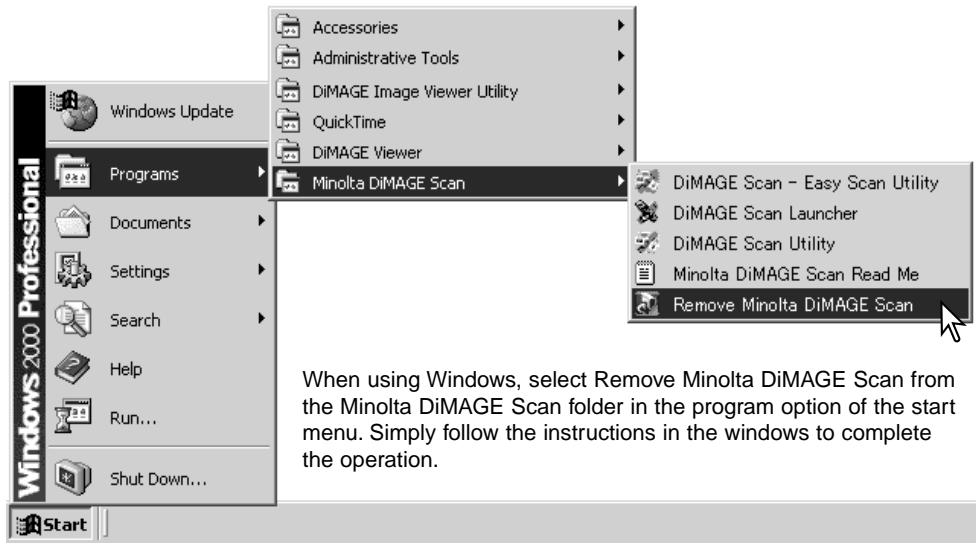
To uninstall the DiIMAGE Scan software from a Macintosh computer, place the DiIMAGE Scan CD-ROM in the CD-ROM drive repeat the installation procedure, but select uninstall from the pop-up menu in the installer dialog box. Confirm the location of the software. Click the uninstall button to remove the software from the computer.
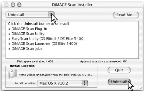
Installed files and folders
The following files and folders are installed in the computer system at the same time as the DiIMAGE Scan Utility application software. For the location and names of the installed scanner profiles, see page 68.
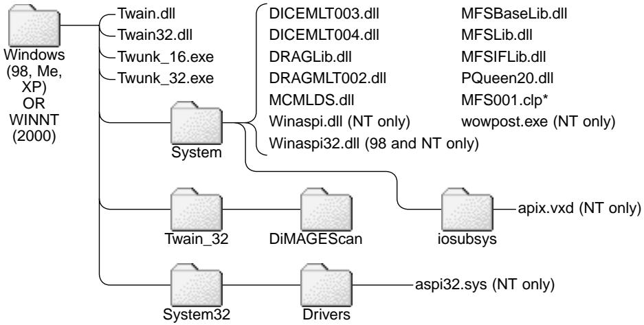
Windows
Mac OS 8/9
Mac OS X
Damage Scan Multi and Multi II system requirements
The following system requirements are for the Dimage Scan Multi and Multi II scanners. Refer to the hardware manual for the requirements of other model scanners. The computer and the operating system must be guaranteed by the manufacturer to support SCSI interface. Check the Minolta web site for the latest compatibility information:
Europe: http://www.minolta support.com
North America: http://www.minoltausa.com
| PC / AT compatible computers | Macintosh |
| Pentium 166MHz or later processor. | PowerPC G3 or later. |
| Windows 98, 98 Second Edition, Me, 2000 Professional, NT 4.0, XP. | Mac OS 8.6 to 9.2.2, and OS X 10.1.3 to 10.1.5. |
| Operation is not guaranteed for custom or home-built machines. The scanner cannot be used with notebook computers. | |
| A minimum of 64 MB (Multi) or 96 MB (Multi II) of RAM is required. 128MB is required with Windows XP. 96 MB is needed when scanning with 16-bit color depth. | A minimum of 64 MB (Multi) or 96 MB (Multi II) of RAM in addition to the requirements for the operating system and applications is required. 96 MB is needed when scanning with 16-bit color depth. |
| 90 MB (Multi) or 600 MB (Multi II) of available hard disk space is required. 200 MB (Multi) or 1.2 GB (Multi II) or more of available hard disk space is needed when scanning with 16-bit color depth. | |
| A High Color (16bit) 640 x 480 pixel monitor is required. 1024 x 768 pixels are recommended. | A 640 x 480 pixel monitor capable of display-ing 32,000 colors is required. 1024 x 768 pixels are recommended. |
| TWAIN driver (Windows) and Plug in (Macintosh) compatible with Photoshop 6.0.1 and 7.0.1, and Photoshop Elements 2.0. | |
| SCSI board must be guaranteed by the manufacturer to work with the computer and operating system. | |
| Recommended SCSI boards: Adaptec SCSI Card 19160, 29160, 29160N, and AVA-2903B. | Recommended SCSI board: Adaptec Power Domain 2930U, 29160N, 2940UW, and 2940U2W as well as the built-in SCSI inter-face supplied by Apple Computer. |
| Digital ROC and GEM system requirements for the Dimage Scan Multi II | |
| Pentium II or later processor. Pentium III or later when scanning with 16-bit color depth. | PowerPC G3 or later. PowerPC G4 processor when scanning with 16-bit color depth. |
| A minimum of 128 MB of RAM. 256 MB or more is recommended. | A minimum of 128 MB of RAM. 192 MB or more is recommended. |
| Required hard disk space: 300MB (35mm), 600MB (Multi-format 35mm), 1.2GB (6X9). With 16-bit color depth: 500MB (35mm), 1GB (Multi-format 35mm), 2GB (6X9). Recommended hard disk space: 600MB (35mm), 1GB (Multi-format 35mm), 2GB (6X9). With 16-bit color depth: 1GB (35mm), 2GB (Multi-format 35mm), 4GB (6X9). | |
About the Dimage Scan Multi and Multi II
The DiIMAGE Scan Utility can be used with the Dimage Scan Multi and Multi II model scanners. However, certain functions are not available:
| DiIMAGE Scan Multi | DiIMAGE Scan Multi II |
| Digital ICE, ROC, and GEM | Digital ICE |
| Pixel Polish | |
| Grain Dissolver | |
| Holder-type list box | |
| Prescan-size list box (Preference window) | |
| Easy Scan Utility | |
| Batch Scan Utility | |
| DiIMAGE Scan Launcher | |
| Manual Focus Dial | |
The input-resolution range for the Dimage Multi is 176 dpi to 2810 dpi for 35mm film and 70 dpi to 1128 dpi with medium-format film. After completing the registration routine with the serial-number button in the preferences window (p 30), the input-resolution range for the Dimage Multi II is 176 dpi to 2810 dpi for 35mm film and 70 dpi to 2810 dpi with medium-format film.
When the DiIMAGE Scan Utility is installed, the scanner profiles listed below are automatically installed for these model scanners, see page 68 for the location. These profiles have been included for advanced color matching with profile-to-profile conversions in sophisticated image-processing or DTP applications. When using these profiles, the color reproduced may not be the same as the color matching system in the utility software.
MLTF3100.icc - used with positive film at any color depth other than 16-bit linear.
MLTF3100p.icc - used with positive film with 16-bit linear color depth.
Record keeping
Keeping records when scanning is important. It allows for results to be reproduced as well as a good reference for settings when new images are scanned. Records are also a useful learning tool; they document both successes and failures.
The data sheet on the following page may be copied and used to record scanner settings. Details on the film, exposure, and any special filters or processing used can be noted.
Image Data Sheet
| Image: | Date: | ||||
| Film: | Exposure: | Filtration: | Processing: | ||
| Image processing | Image-correction Job: | ||||
| Brightness, contrast, & color balance palette | Hue, saturation & lightness palette | Unsharp mask | Selective-color palette | ||
| Brightness: | Hue: | Amount: | Cyan: R/ G/ B/ C/ M/ Y/ | ||
| Contrast: | Saturation: | Radius: | Magenta: R/ G/ B/ C/ M/ Y/ | ||
| Red: | Lightness: | Threshold: | Yellow R/ G/ B/ C/ M/ Y/ | ||
| Green: | Shadow: | Black: R/ G/ B/ C/ M/ Y/ | |||
| Blue: | Digital ICE: | Digital ROC: | Digital GEM: | ||
| Exposure control | Exposure-control setting file: | ||||
| Master: | Red: | Green: | Blue: | ||
| Scan settings | Job name: | ||||
| Input resolution: | Input size (W): | Input size (H): | Magnification: | ||
| Output resolution: | Output size (W): | Output size (H): | Unit: | ||
| Color matching | Color space: | ICC profile: | |||
| Preferences | Auto exposure: | Color depth: | Multi-sample scan: | ||
| Notes:Minolta | |||||
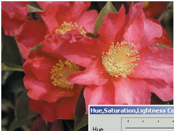
Hue corrections
Changes in hue rotate the original color values though a color space and reassigns a new hue based on the new position in that space. In this example, the original image was rotated 180^ . For more on the hue, saturation, and brightness palette, see page 56.
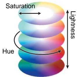
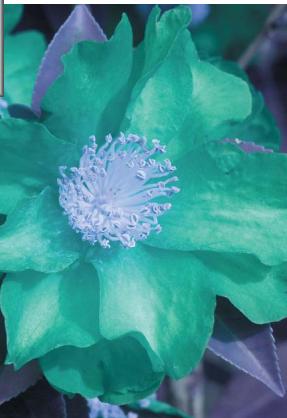
Two color spaces are displayed at the bottom of the palette. The top bar indicates the color space of the original image. The bottom bar displays the relative shift to the Original color space. In the example, the reds have been shifted to green and the yellows to lavender.
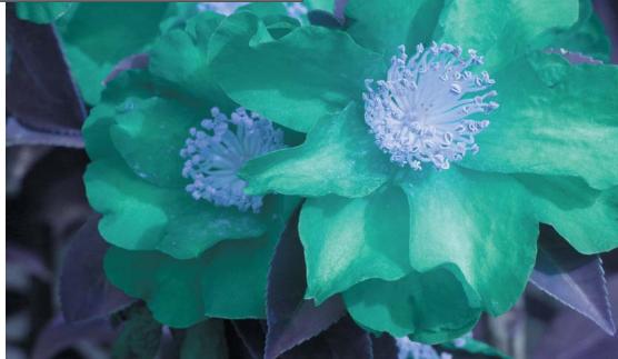
Selective-color palette
In the original image, the colors were muted making the whole scene flat. By subtracting cyan from the red channel, the bridge and faint details in the clouds could be accentuated. The cloud detail was further enhanced by subtracting yellow from the blue channel. For more on the selective-color palette, see page 57.
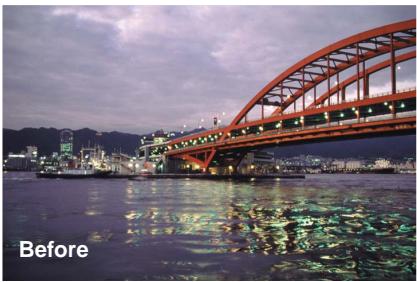
MINLTA
We offer support for our digital products 24 hours per day on www.minoltasupport.com.
Camera know-how, image composition, digital image editing: discover more about Minolta's new internet world and visit www.minoltaphotoworld.com
© 2003 Minolta Co., Ltd. under the Berne Convention and the Universal Copyright Convention.