
GA-6WFZ7-E - Équipement électronique GIGABYTE - Notice d'utilisation et mode d'emploi gratuit
Retrouvez gratuitement la notice de l'appareil GA-6WFZ7-E GIGABYTE au format PDF.
| Type de produit | Carte mère |
| Marque | GIGABYTE |
| Modèle | GA-6WFZ7-E |
| Format | FlexATX (22,8 cm x 19,1 cm) |
| Socket processeur | Socket 370 |
| Chipset | Intel 810 (GMCH 82810/82810E + ICH 82801AA) |
| Mémoire vive | 2 slots DIMM 168 broches, PC-100 SDRAM, max. 512 Mo |
| Slots d'extension | 1 PCI 32-bit, 1 AMR, 1 TV/DFP |
| Stockage | 2 ports IDE (Ultra DMA/ATA 66), 1 port disquette |
| Connecteurs arrière | 1 série (COMA), 1 parallèle, 4 USB, PS/2 clavier/souris, VGA intégré, ports audio (option) |
| Audio intégré | Optionnel : Aureal AU8810 |
| LAN intégré | Optionnel : Intel 82559 |
| BIOS | Award BIOS 4 Mbit Flash ROM |
| Alimentation | Connecteur ATX 20 broches, support ATX 2.01 |
| Fonctions spéciales | Suspend to RAM (STR), réveil par clavier/souris/LAN/modem, surveillance matérielle |
| Sécurité | Conformité FCC et CE, protection écriture BIOS (FWH Write Protection) |
| Entretien | Nettoyage avec un chiffon sec et doux, éviter l'humidité |
| Réparabilité | Pièces détachées : batterie CMOS, ventilateurs. Réparation par un professionnel recommandée. |
FOIRE AUX QUESTIONS - GA-6WFZ7-E GIGABYTE
Questions des utilisateurs sur GA-6WFZ7-E GIGABYTE
0 question sur cet appareil. Repondez a celles que vous connaissez ou posez la votre.
Poser une nouvelle question sur cet appareil
Téléchargez la notice de votre Équipement électronique au format PDF gratuitement ! Retrouvez votre notice GA-6WFZ7-E - GIGABYTE et reprennez votre appareil électronique en main. Sur cette page sont publiés tous les documents nécessaires à l'utilisation de votre appareil GA-6WFZ7-E de la marque GIGABYTE.
MODE D'EMPLOI GA-6WFZ7-E GIGABYTE
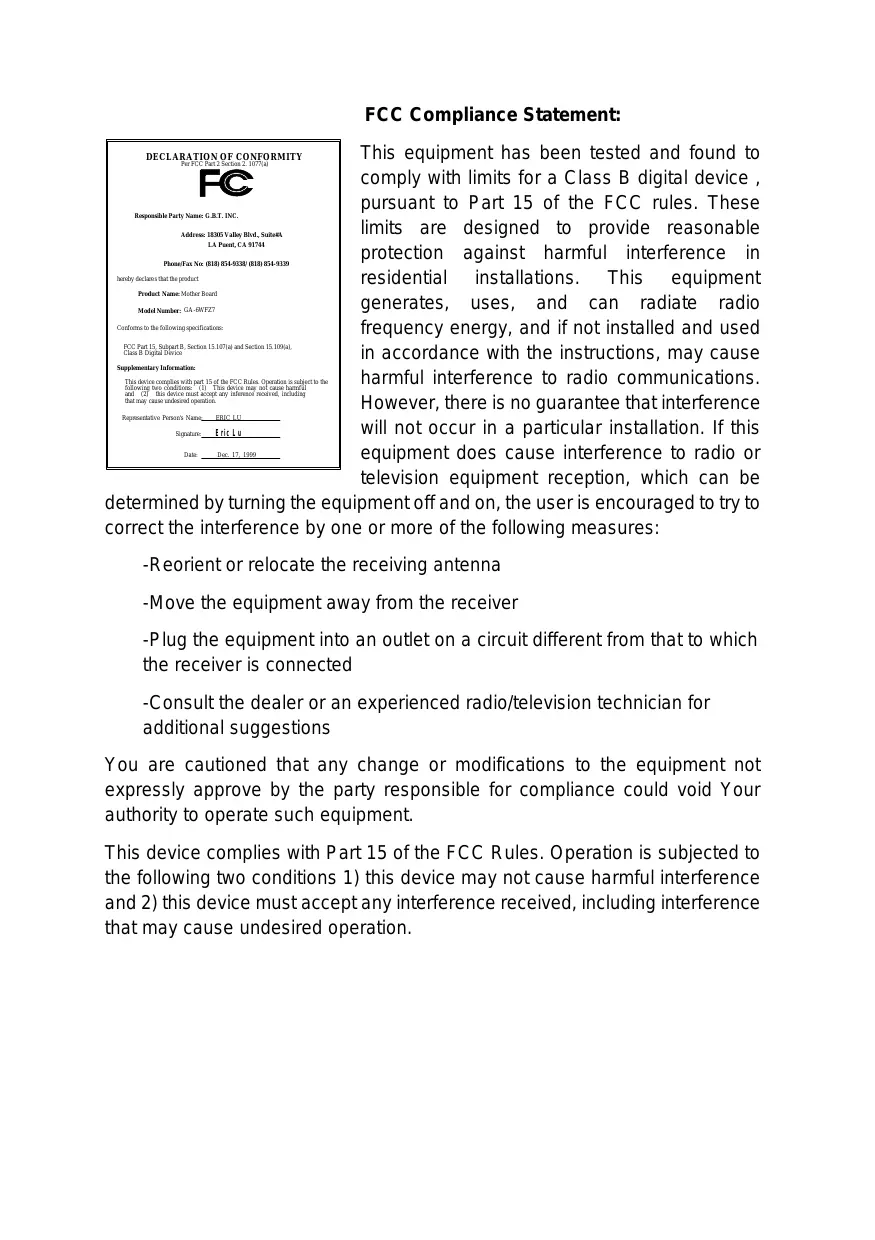
FCC Compliance Statement:

This equipment has been tested and found to comply with limits for a Class B digital device, pursuant to Part 15 of the FCC rules. These limits are designed to provide reasonable protection against harmful interference in residential installations. This equipment generates, uses, and can radiate radio frequency energy, and if not installed and used in accordance with the instructions, may cause harmful interference to radio communications. However, there is no guarantee that interference will not occur in a particular installation. If this equipment does cause interference to radio or television equipment reception, which can be
determined by turning the equipment off and on, the user is encouraged to try to correct the interference by one or more of the following measures:
-Reorient or relocate the receiving antenna
-Move the equipment away from the receiver
-Plug the equipment into an outlet on a circuit different from that to which the receiver is connected
-Consult the dealer or an experienced radio/television technician for additional suggestions
You are cautioned that any change or modifications to the equipment not expressly approve by the party responsible for compliance could void Your authority to operate such equipment.
This device complies with Part 15 of the FCC Rules. Operation is subjected to the following two conditions 1) this device may not cause harmful interference and 2) this device must accept any interference received, including interference that may cause undesired operation.
Declaration of Conformity
We, Manufacturer/Importer
(full address)
G.B.T. Technology Trading GmbH
Ausschlager Weg 41, 1F, 20537 Hamburg, Germany
declare that the product
( description of the apparatus, system, installation to which it refers)
Mother Board
GA-6WFZ7
is in conformity with
(reference to the specification under which conformity is declared)
in accordance with 89/336 EEC-EMC Directive
EN55011
Limits and methods of measurement of radio disturbance characteristics of industrial, scientific and medical (ISM) high frequency equipment
EN61000-3-2
EN60555-2
Disturbances in supply systems caused by household appliances and similar electrical equipment "Harmonics"
EN55013
Limits and methods of measurement of radio disturbance characteristics of broadcast receivers and associated equipment
EN61000-3-3* EN60555-3
Disturbances in supply systems caused by household appliances and similar electrical equipment "Voltage fluctuations"
EN55014
Limits and methods of measurement of radio disturbance characteristics of household electrical appliances, portable tools and similar electrical apparatus
EN50081-1
Generic emission standard Part 1: Residual, commercial and light industry
EN55015
Limits and methods of measurement of radio disturbance characteristics of fluorescent lamps and luminaries
EN55081-2
Generic immunity standard Part 1: Residual, commercial and light industry
EN55020
Immunity from radio interference of broadcast receivers and associated equipment
EN55082-2
Generic immunity standard Part 2: Industrial environment
EN55022
Limits and methods of measurement of radio disturbance characteristics of information technology equipment
ENV55104
Immunity requirements for household appliances tools and similar apparatus
DIN VDE 0855 part 10 part 12
Cabled distribution systems; Equipment for receiving and/or distribution from sound and television signals
EN50091-2
EMC requirements for uninterruptible power systems (UPS)
CE marking

(EC conformity marking)
The manufacturer also declares the conformity of above mentioned product with the actual required safety standards in accordance with LVD 73/23 EEC
EN60065
Safety requirements for mains operated electronic and related apparatus for household and similar general use
EN60950
Safety for information technology equipment including electrical business equipment
EN60335
Safety of household and similar electrical appliances
EN50091-1
General and Safety requirements for interruptible power systems (UPS)
Manufacturer/Importer
(Stamp)
Date: Dec. 17, 1999
Signature: Rex Lin
Name : Rex Lin
6WFZ7 Series
Intel® 810 Socket 370 Motherboard
USER'S MANUAL
INTEL® 810 Socket 370 Processor MAINBOARD
REV. 2.0 First Edition
R-20-01-091214
How This Manual Is Organized
This manual is divided into the following sections:
| 1) Revision List | Manual revision information |
| 2) Item Checklist | Product item list |
| 3) Features | Product information & specification |
| 4) Hardware Setup | Instructions on setting up the motherboard |
| 5) Performance & Block Diagram | Product performance & block diagram |
| 6) Suspend to RAM | Instructions STR installation |
| 7) BIOS Setup | Instructions on setting up the BIOS software |
| 8) Appendix | General reference |
Table Of Content
| Revision History | P.1 |
| Item Checklist | P.2 |
| Summary of Features | P.3 |
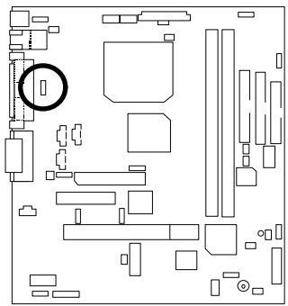
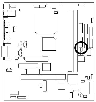
| 6WFZ7 Series Motherboard Layout | P.5 |
| Page Index for CPU Speed Setup / Connectors / Panel and Jumper Definition | P.6 |
| Performance List | P.29 |
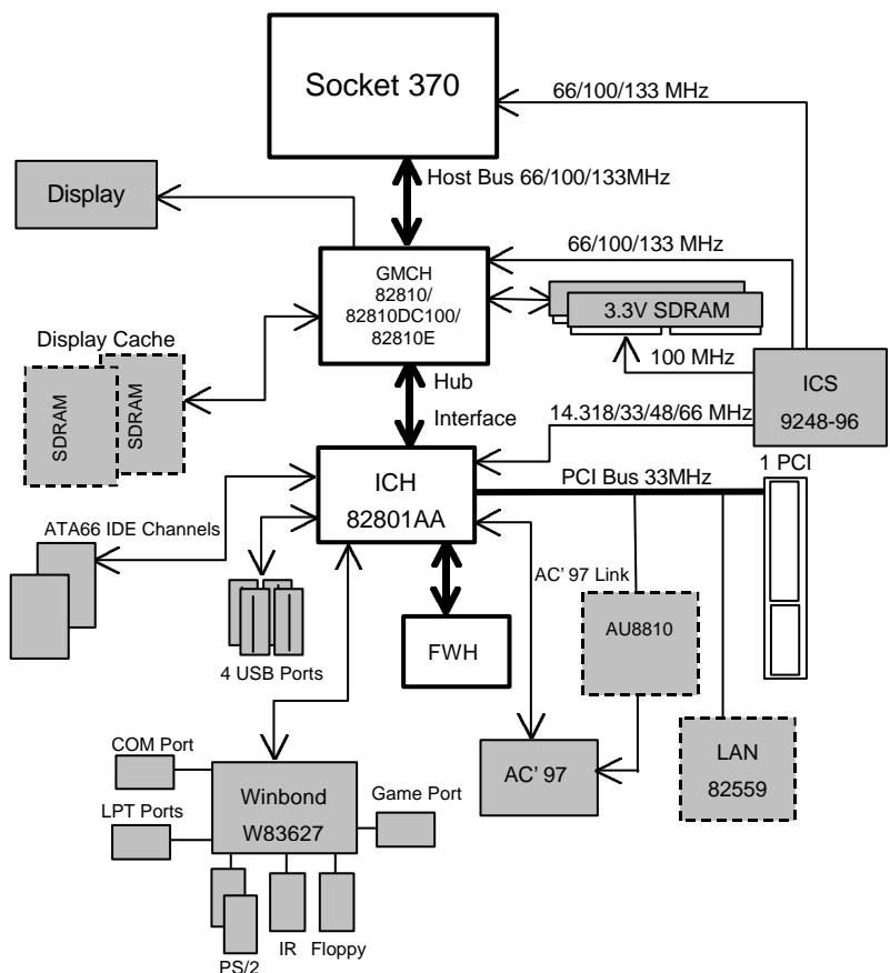
| Block Diagram | P.30 |
| Suspend RAM Installation | P.31 |
| Memory Installation | P.37 |
| Page Index for BIOS Setup | P.38 |
| Appendix | P.72 |
Revision History
| Revision | Revision Note | Date |
| 2.0 | Initial release of the 6WFZ7 Series motherboard user's manual. | Dec.1999 |
The author assumes no responsibility for any errors or omissions that may appear in this document nor does the author make a commitment to update the information contained herein. Third-party brands and names are the property of their respective owners.
Item Checklist
The 6WFZ7 Series Motherboard
Cable for IDE / Floppy device
l Diskettes or CD (IUCD) for motherboard driver & utilities
□Internal COMB Cable (Optional)
□ Internal USB Cable (Optional)
Cable for SCSI device
6WFZ7 Series User's Manual
□ Internal DFP and TV-Out Cable (Optional)
Summary of Features
| Form factor | • 22.8 cm x 19.1 cm FlexATX Size form factor, 4 layers PCB. |
| Motherboard | • 6WFZ7 series includes 6WFZ7, 6WFZ7-M, 6WFZ7-E |
| CPU | • Socket 370 Processor • 128 KB 2nd cache in CPU(Depend on CPU) |
| Chipset | Intel® 810 ,consisting of: • 82810/82810-DC100/82810E Graphics and memory Controller Hub(GMCH) • 82801AA I/O Controller Hub(ICH) |
| Clock Generator | • Supports 66 / 100 / 133MHz (133MHz only GMCH82810E support) |
| Memory | • 2 168-pin DIMM Sockets • Supports PC-100 SDRAM 16MB~512MB(Max) • Supports only 3.3V SDRAM DIMM |
| I/O Control | • Winbond W83627 |
| Slots | • 1 AMR • 1 32-bit Master PCI Bus slot • 1 TV/DFP slot |
| On-Board IDE | • An IDE controller on the Intel® 82801AA PCI chipset provides IDE HDD/ CD-ROM with PIO, Bus Master and Ultra DMA33/ATA 66 operation modes • Can connect up to four IDE devices |
| On-Board Peripherals | • 1 Floppy port supports 2 FDD with 360K, 720K,1.2M, 1.44M and 2.88M bytes • 1 Parallel ports supports SPP/EPP/ECP mode • 1 Serial Ports (COMA) • 4 USB ports • 1 IrDA connector for IR |
| On-Board Sound (Optional) | • Aureal AU8810(Optional) • Line In / Line Out / Mic In / AUX In / CD In / TEL / SPDIF / Game Port |
| BIOS | • Licensed AWARD BIOS, 4M bit FLASH ROM |
| On-Board LAN | • Intel® 82559(Optional) |
| PS/2 Connector | • PS/2® Keyboard interface and PS/2® Mouse interface |
To be continued...
| Hardware Monitor | • CPU/Power Supply/System Fan Revolution Detect • CPU / Power / System Fan Control • System Voltage Detect • CPU Overheat Warning • Chassis Intrusion Detect • Display Actual Current Voltage |
| Additional Features | • Internal/External Modem Wake up • Keyboard Password Wake up • LAN Wake up • System after AC back • Support STR Function |
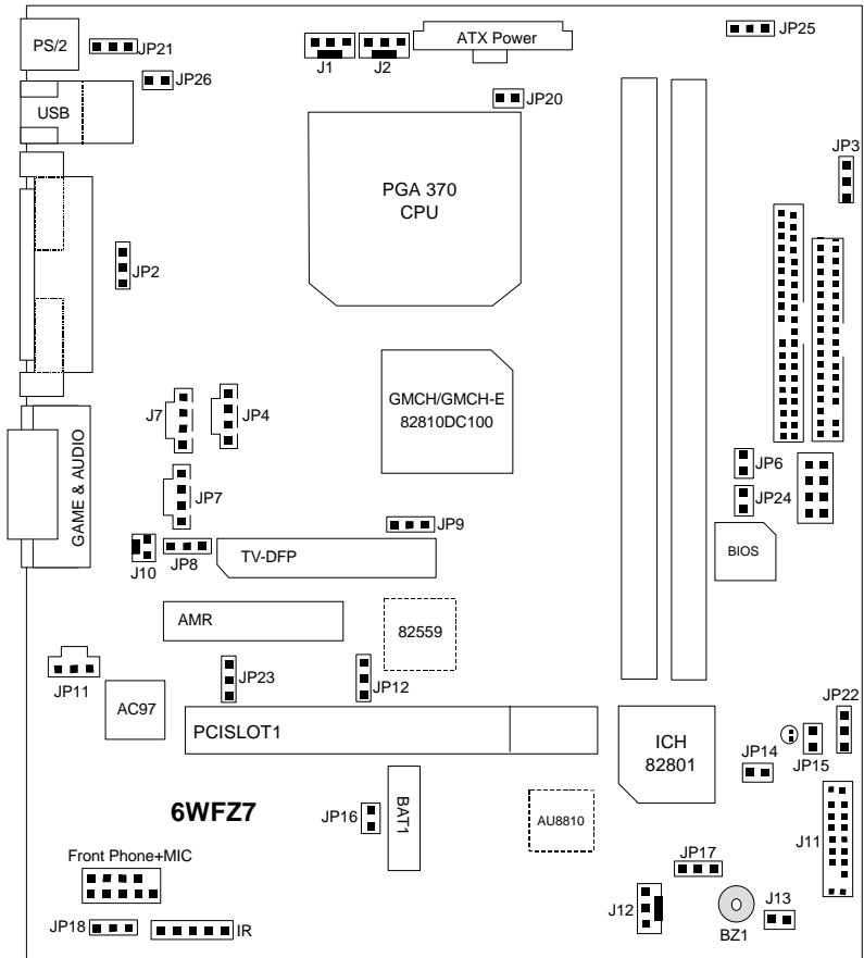
6WFZ7 Series Motherboard Layout
| Page Index for CPU Speed Setup / Connectors / Panel and Jumper Definition | Page |
| CPU Speed Setup | P.8 |
| Connectors | P.9 |
| COMA / VGA / LPT Port | P.9 |
| Game & Audio Port | P.9 |
| LAN & USB Connector | P.10 |
| TV/DFP | P.10 |
| PS/2 Keyboard & PS/2 Mouse Connector | P.11 |
| CPU Cooling FAN Power Connector | P.11 |
| Power Cooling FAN Power Connector | P.12 |
| System Cooling FAN Power Connector | P.12 |
| ATX Power | P.13 |
| Floppy Port | P.13 |
| IDE 1(Primary)/ IDE 2(Secondary) Port | P.14 |
| USB Port | P.14 |
| Front Phone+MIC | P.15 |
| IR | P.15 |
| J7(CD Audio Line In) | P.16 |
| JP4(TEL) | P.16 |
| JP7(AUX IN) | P.17 |
| J10(Ring Power On) [Internal Modem Card Wake Up] | P.17 |
| JP15 (STR LED Connector & DIMM LED) | P.18 |
| JP11(SPDIF)[Optional] | P.18 |
| Panel and Jumper Definition | P.19 |
| J11 (2x11 pins jumper) | P.19 |
| JP21 (Rear USB Device Wake up Selection) | P.20 |
| JP2 (PS/2 Keyboard Power On) | P.20 |
| JP6 (Top Block Lock) | P.21 |
| JP9 (Onboard Sound Function Selection)[Optional] | P.21 |
| JP8 (AMR Selection) | P.22 |
| JP12 (Onboard LAN Function) [Optional] | P.22 |
| JP14 (Timeout Reboot Function) | P.23 |
| JP16 (Case Open) | P.23 |
| JP17 (Safe mode/Recovery/Normal) | P.24 |
| JP18 (Clear CMOS Function) | P.24 |
| J13(Buzzer Enable)[Optional] | P.25 |
6WFZ7 Series Motherboard
| JP20 (STR Function Selection) | P.25 |
| JP26 (LAN LED) [Optional] | P.26 |
| JP24 (FWH Write Protection) | P.26 |
| JP22 (Front USB Device Wake up Function) | P.27 |
| JP23 (Onboard LAN Wake up Function) [Optional] | P.27 |
| BAT 1 | P.28 |
CPU Speed Setup
The system bus frequency can be switched at 66MHz, 100MHz, 133MHz and Auto by adjusting JP3/JP25 (See Figure-1). The CPU Frequency is control by BIOS.
The CPU speed must match with the frequency RATIO. It will cause system hanging up if the frequency RATIO is higher than that of CPU.
JP3/JP25 : CPU Speed Setup
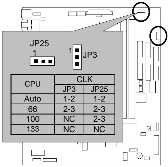
Figure-1
Note: Please set the CPU host frequency in accordance with your processor's specifications. We don't recommend you to set the system bus frequency over the CPU's specification because these specific bus frequencies are not the standard specifications for CPU, chipset and most of the peripherals. Whether your system can run under these specific bus frequencies properly will depend on your hardware configurations, including CPU, Chipsets, SDRAM, Cards... .etc.
Note: JP25 is only available when the motherboard use 82810E chipset.
Note: 133MHz only 82810E support.
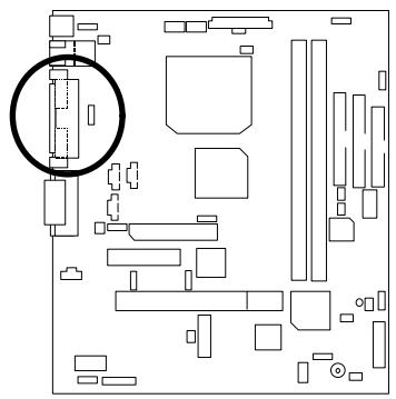
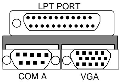
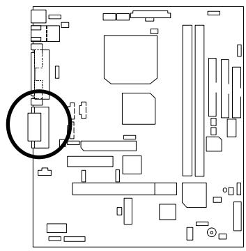
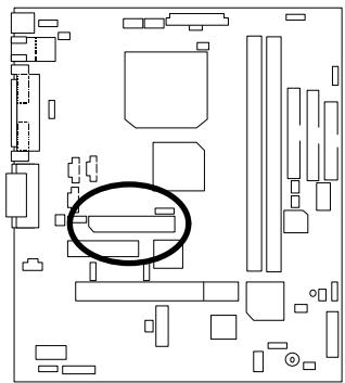
Connectors
COM A / VGA / LPT Port
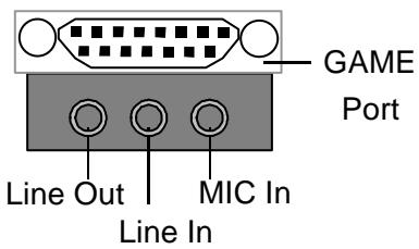
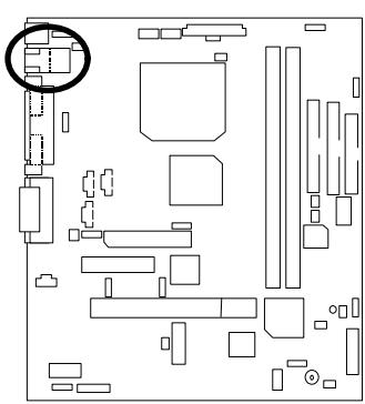
Game & Audio Port
LAN & USB Connector
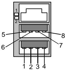
1 - Green LED
(LAN Link LED)
2 -Yellow LED
(LAN Active LED)
| Pin No. | Definition |
| 1 | USB V0 |
| 2 | USB D0- |
| 3 | USB D0+ |
| 4 | GND |
| 5 | USB V1 |
| 6 | USB D1- |
| 7 | USB D1+ |
| 8 | GND |
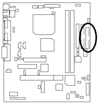
TV/DFP : TV-Out / Digital Flat Panel Daughter card connector.

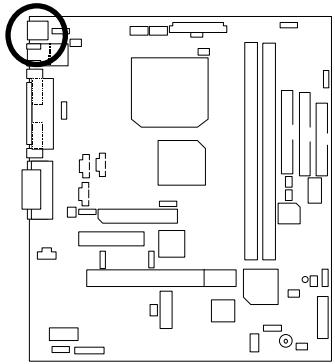
PS/2 Keyboard & PS/2 Mouse Connector
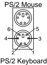
| PS/2 Mouse/ Keyboard | |
| Pin No. | Definition |
| 1 | Data |
| 2 | NC |
| 3 | GND |
| 4 | VCC(+5V) |
| 5 | Clock |
| 6 | NC |
CPU Cooling FAN Power Connector
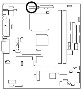

| Pin No. | Definition |
| 1 | GND |
| 2 | +12V |
| 3 | SENSE |
Power Cooling FAN Power Connector
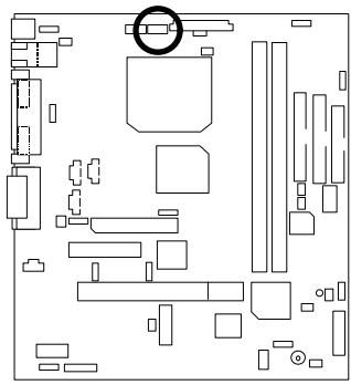

| Pin No. | Definition |
| 1 | GND |
| 2 | +12V |
| 3 | SENSE |
System Cooling FAN Power Connector
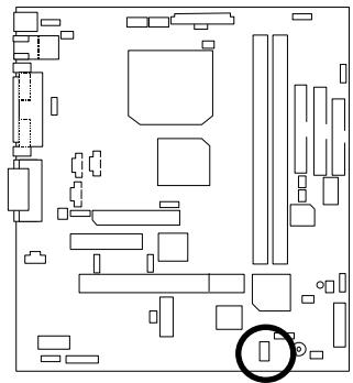

| Pin No. | Definition |
| 1 | GND |
| 2 | +12V |
| 3 | SENSE |
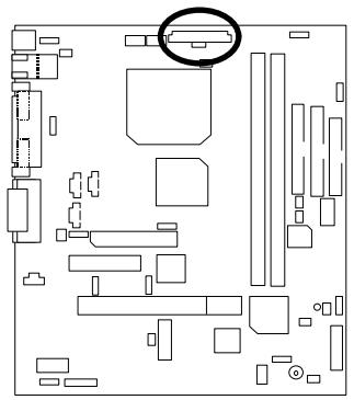
ATX Power
| 1 | 10 | |||||||
| 11 | 20 |
| Pin No. | Definition |
| 3,5,7,13,15-17 | GND |
| 1,2,11 | 3.3V |
| 4,6,19,20 | VCC |
| 10 | +12V |
| 12 | -12V |
| 18 | -5V |
| 8 | Power Good |
| 9 | 5V SB stand by+5V |
| 14 | PS-ON(Soft On/Off) |
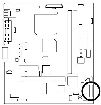
Floppy Port

IDE1(Primary), IDE2 (Secondary) Port

USB Port

| Pin No. | Definition |
| 1 | USB V0 |
| 2 | USB D0- |
| 3 | USB D0+ |
| 4 | GND |
| 5 | USB V1 |
| 6 | USB D1- |
| 7 | USB D1+ |
| 8 | GND |
Front Phone+MIC

| Pin No. | Definition |
| 1 | SPK_R |
| 2 | GND |
| 3 | GND |
| 4 | SPK_L |
| 5 | GND |
| 6 | MIC-REF |
| 7 | GND |
| 8 | GND |
| 9 | MIC |
| 10 | NC |
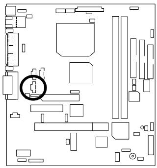
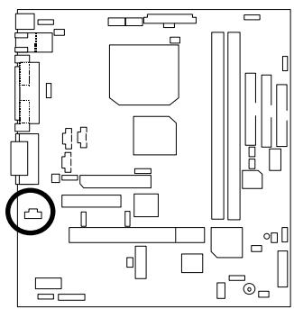
IR

1
| Pin No. | Definition |
| 1 | VCC(+5V) |
| 2 | NC |
| 3 | IR Data Input |
| 4 | GND |
| 5 | IR Data Output |
J7 : CD Audio Line In

| Pin No. | Definition |
| 1 | CD-L |
| 2 | GND |
| 3 | GND |
| 4 | CD-R |
JP4: TEL (The connector is for modem with internal voice connector)

| Pin No. | Definition |
| 1 | Signal-In |
| 2 | GND |
| 3 | GND |
| 4 | Signal-Out |
JP7:AUXIN

| Pin No. | Definition |
| 1 | AUX-L |
| 2 | GND |
| 3 | GND |
| 4 | AUX-R |
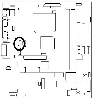
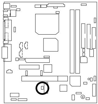
J10: Ring Power On (Internal Modem Card Wake Up)
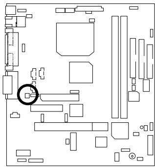

| Pin No. | Definition |
| 1 | Signal |
| 2 | GND |
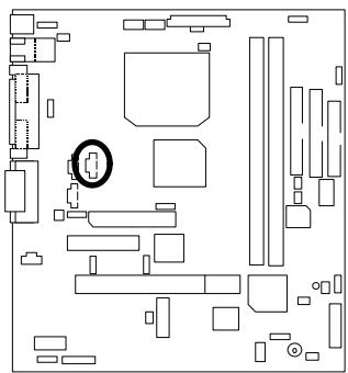
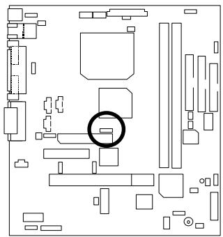
JP15:STRLEDConnector&DIMMLED
STR LED Connector External


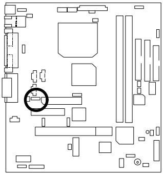
JP11 : SPDIF(The SPDIF output is capable of providing digital audio to external speakers or compressed AC3 data to an external Dobly digital decoder.) (Optional)

| Pin No. | Definition |
| 1 | VCC |
| 2 | SPDIF OUT |
| 3 | GND |
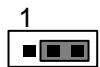
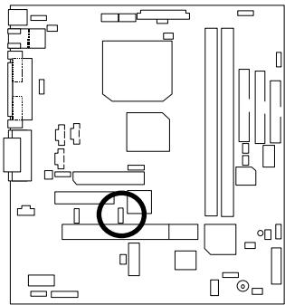
Panel and Jumper Definition
J11: For 2X11 Pins Jumper
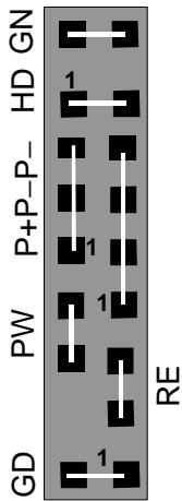
| GN (Green Switch) | Open: Normal Operation Close: Entering Green Mode |
| GD (Green LED) | Pin 1: LED anode(+) Pin 2: LED cathode(-) |
| HD (IDE Hard Disk Active LED) | Pin 1: LED anode(+) Pin 2: LED cathode(-) |
| SPK (Speaker Connector) | Pin 1: VCC(+) Pin 2- Pin 3: NC Pin 4: Data(-) |
| RE (Reset Switch) | Open: Normal Operation Close: Reset Hardware System |
| P+P-P-(Power LED) | Pin 1: LED anode(+) Pin 2: LED cathode(-) Pin 3: LED cathode(-) |
| PW (Soft Power Connector) | Open: Normal Operation Close: Power On/Off |
JP21: Rear USB Device Wake up Selection (USB Connector CN2)

| Pin No. | Definition |
| 1-2 close | Enabled Rear USB Device Wake up |
| 2-3 close | Disabled Rear USB Device Wake up(Default) |
(If you want to use "USB KB/Mouse Wake from S3" function, you have to set the BIOS setting "USB KB/Mouse Wake from S3" enabled, and the jumper "JP21" enabled).
* (Power on the computer and as soon as memory counting starts, press < Del> . You will enter BIOS Setup. Select the item "POWER MANAGEMENT SETUP", then select USB
KB/Mouse Wake from S3". Remember to save the setting by pressing "ESC" and choose the "SAVE & EXIT SETUP" option.)
JP2:PS/2 Keyboard Power On

| Pin No. | Definition |
| 1-2 close | PS/2 Keyboard Power on Enabled |
| 2-3 close | PS/2 Keyboard Power on Disabled (Default) |
JP6 : Top Block Lock

| Pin No. | Definition |
| Open | Top Block Lock |
| Close | Top Block Unlock (Default) |
JP9 : Onboard Sound Function Selection (Optional)

| Pin No. | Definition |
| 1-2 close | Onboard Sound Enable(Default) |
| 2-3 close | Onboard Sound Disable |
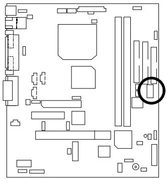
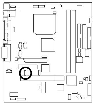
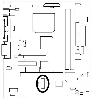
JP8 : AMR Selection

| Pin No. | Definition |
| 1-2close | AMR Secondary |
| 2-3close | AC97 Disabled (Default) (Disabled Onboard CODEC) |
JP12 : Onboard LAN Function (Optional)

| Pin No. | Definition |
| 1-2 close | Onboard LAN Disabled |
| 2-3 close | Onboard LAN Enabled (Default) |
JP14 : Timeout Reboot Function

| Pin No. | Definition |
| Open | Timeout Reboot |
| Close | No Reboot on Timeout (Default) |
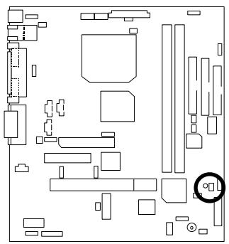
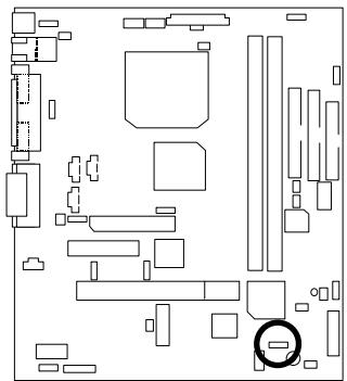
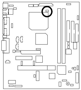
JP16 : Case Open

| Pin No. | Definition |
| 1 | Signal |
| 2 | GND |
JP17: Safe mode/Recovery/Normal

| Pin No. | Definition |
| 1-2close | Normal(Default) |
| 2-3close | Safe mode |
| 1-2-3open | Recovery |
JP18 : Clear CMOS Function

| Pin No. | Definition |
| 1-2 close | Clear CMOS |
| 2-3 close | Normal (Default) |
J13: Buzzer Enable (Optional)
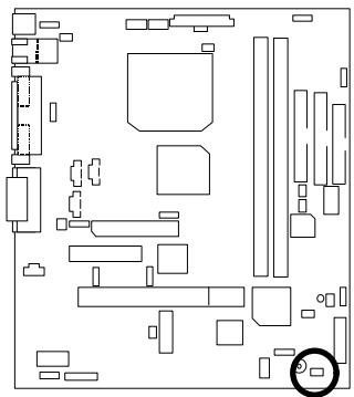

| Pin No. | Definition |
| Open | Internal Buzzer Disabled |
| Close | Internal Buzzer Enabled (Default) |
JP20:STR Function Selection

| Pin No. | Definition |
| Open | STR Disabled(Default) |
| Close | STR Enabled |
JP26:LANLED(Optional)

| Pin No. | Definition |
| 1 | VCC |
| 2 | Single |
JP24 : FWH Write Protection

| Pin No. | Definition |
| Close | Write Protection |
| Open | Normal (Default) |
JP22: Front USB Device Wake up Function (USB Port J9)
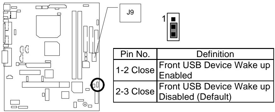
(If you want to use "USB KB/Mouse Wake from S3" function, you have to set the BIOS setting 'USB KB/Mouse Wake from S3" enabled, and the jumper " JP22" enabled).
* (Power on the computer and as soon as memory counting starts, press . You will enter BIOS Setup. Select the item "POWER MANAGEMENT SETUP", then select "USB KB/Mouse Wake from S3". Remember to save the setting by pressing "ESC" and choose the "SAVE & EXIT SETUP" option.)
JP23 : Onboard LAN Wake up Function(Optional)

| Pin No. | Definition |
| 1-2 close | Onboard LAN Wake up Enabled |
| 2-3 close | Onboard LAN Wake up Disabled(Default) |
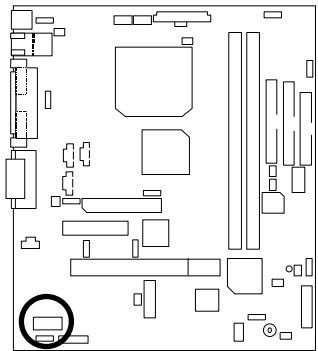
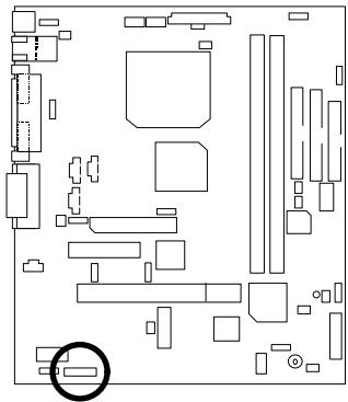
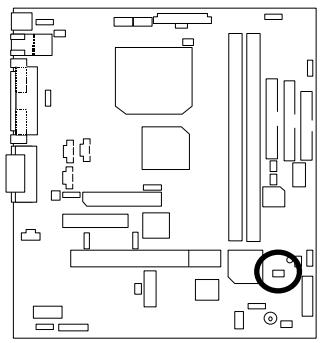
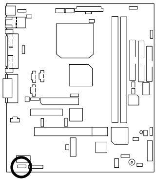
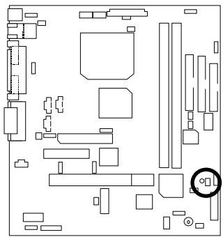
BAT1: Battery

≈ Danger of explosion if battery is incorrectly replaced.
Replace only with the same or equivalent type recommended by the manufacturer.
Dispose of used batteries according to the manufacturer's instructions.
Performance List
The following performance data list is the testing results of some popular benchmark testing programs.
These data are just referred by users, and there is no responsibility for different testing data values gotten by users. (The different Hardware & Software configuration will result in different benchmark testing results.)
CPU Intel® Celeron™ 533MHz Socket 370 processor
DRAM (128x1)MB SDRAM (LGS GM72V66841ET7J)
- Cache SIZE 128 KB included in CPU
- DISPLAY Onboard Intel Corporation 810 Graphics Controller Hub (4MB SDRAM)
- STORAGE Onboard IDE (Quantum KA13600AT)
O.S. Windows NT™4.0 SPK5
- DRIVER Display Driver at 1024 x 768 65536 colors 75Hz. Intel Ultra ATA Storage Driver V5.0 Engineering Sample
| Processor | Intel® Celeron™ |
| 533MHz(66x8) | |
| Winbench99 | |
| CPU mark 99 | 38.9 |
| FPU Winmark 99 | 2860 |
| Business Disk Winmark 99 | 5160 |
| Hi-End Disk Winmark 99 | 13000 |
| Business Graphics Winmark 99 | 149 |
| Hi-End Graphics Winmark 99 | 383 |
| Winstone99 | |
| Business Winstone99 | 30.5 |
| Hi-End Winstone99 | 28.2 |
Block Diagram
Suspend to RAM Installation
A.1 Introduce STR function:
Suspend-to-RAM (STR) is a Windows 98 ACPI sleep mode function. When recovering from STR (S3) sleep mode, the system is able, in just a few seconds, to retrieve the last "state" of the system before it went to sleep and recover to that state. The "state" is stored in memory (RAM) before the system goes to sleep. During STR sleep mode, your system uses only enough energy to maintain critical information and system functions, primarily the system state and the ability to recognize various "wake up" triggers or signals, respectively.
A.2 STR function Installation
Please use the following steps to complete the STR function installation.
Step-By-Step Setup
Step 1:
To utilize the STR function, the system must be in Windows 98 ACPI mode.
Putting Windows 98 into ACPI mode is fairly easy.
Setup with Windows 98 CD:
A. Insert the Windows 98 CD into your CD-ROM drive, select Start, and then Run.
B. Type (without quotes) "D:\setup\p j" in the window provided. Hit the enter key or click OK.
C. After setup completes, remove the CD, and reboot your system
(This manual assumes that your CD-ROM device drive letter is D:).
Step 2:
(If you want to use STR Function, please set jumper JP20 Closed.)

| Pin No. | Definition |
| Open | STR Disabled(Default) |
| Close | STR Enabled |
Step 3:
Power on the computer and as soon as memory counting starts, press . You will enter BIOS Setup. Select the item "POWER MANAGEMENT SETUP", then select "ACPI Suspend Type: S3 (Suspend to RAM)". Remember to save the settings by pressing "ESC" and choose the "SAVE & EXIT SETUP" option.
Congratulations! You have completed the installation and now can use the STR function.
A.3 How to put your system into STR mode?
There are two ways to accomplish this:
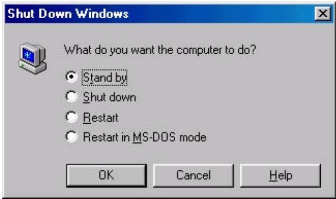
- Choose the "Stand by" item in the "Shut Down Windows" area.
A. Press the "Start" button and then select "Shut Down"
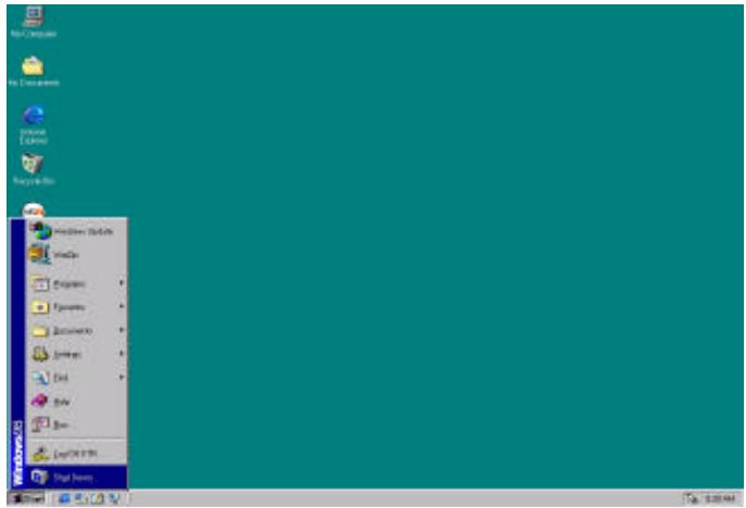
B. Choose the "Stand by" item and press "OK"
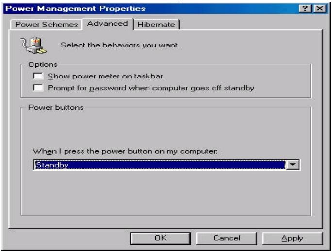
- Define the system "power on" button to initiate STR sleep mode:
A. Double click "My Computer" and then "Control Panel"
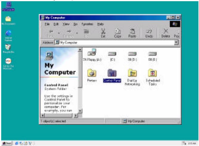
B. Double click the "Power Management" item.
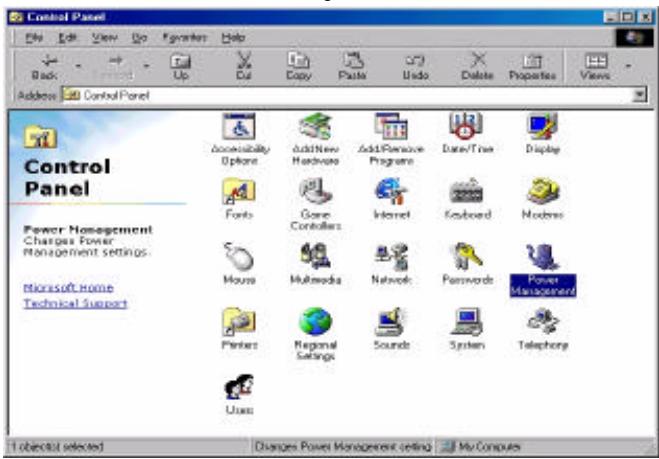
C. Select the "Advanced" tab and "Standby" mode in Power Buttons.
Step 4:
Restart your computer to complete setup.
Now when you want to enter STR sleep mode, just momentarily press the "Power on" button...
A.4 How to recover from the STR sleep mode?
There are seven ways to "wake up" the system:
- Press the "Power On" button.
- Use the "Keyboard Power On" function.
- Use the "Mouse Power On" function.
- Use the "Resume by Alarm" function.
- Use the "Modem Ring On" function.
- Use the "Wake On LAN" function.
- Use the "USB Device Wake up" function.
A.5 Notices :
In order for STR to function properly, several hardware and software requirements must be satisfied:
A. Your ATX power supply must comply with the ATX 2.01 specification (provide more than 720mA 5V Stand-By current).
B. Your SDRAM must be PC-100 compliant.
- Connector JP15 is provided to connect to the STR LED in your system chassis. [Your chassis may not provide this feature.] The STR LED will be illuminated when your system is in STR sleep mode.
STR LED Connector External


DIMM LED
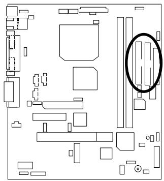
Memory Installation
The motherboard has 2 dual inline memory module (DIMM) sockets. The BIOS will automatically detects memory type and size. To install the memory module, just push it vertically into the DIMM Slot. The DIMM module can only fit in one direction due to the two notch. Memory size can vary between sockets.
Install memory in any combination table:
| DIMM | 168-pin SDRAM DIMM Modules | |
| DIMM1 | Supports 16 / 32 / 64 / 128 / 256 MB | X 1 pcs |
| DIMM2 | Supports 16 / 32 / 64 / 128 / 256 MB | X 1 pcs |
| Page Index for BIOS Setup | Page |
| The Main Menu | P.40 |
| Standard CMOS Features | P.43 |
| Advanced BIOS Features | P.47 |
| Advanced Chipset Features | P.51 |
| Integrated Peripherals | P.53 |
| Power Management Setup | P.58 |
| PnP/ PCI Configuration | P.62 |
| PC Health Status | P.64 |
| Frequency / Voltage Control | P.66 |
| Load Fail-Safe Defaults | P.67 |
| Load Optimized Defaults | P.68 |
| Set Supervisor / User Password | P.69 |
| SAVE to CMOS and EXIT | P.70 |
| EXIT Without Saving | P.71 |
BIOS Setup
BIOS Setup is an overview of the BIOS Setup Program. The program that allows users to modify the basic system configuration. This type of information is stored in battery-backed CMOS RAM so that it retains the Setup information when the power is turned off.
ENTERING SETUP
Power ON the computer and press immediately will allow you to enter Setup. If the message disappears before you respond and you still wish to enter Setup, restart the system to try again by turning it OFF then ON or pressing the "RESET" bottom on the system case. You may also restart by simultaneously press keys.
CONTROL KEYS
| <↑> | Move to previous item |
| <↓> | Move to next item |
| <←> | Move to the item in the left hand |
| <→> | Move to the item in the right hand |
| <Esc> | Main Menu - Quit and not save changes into CMOS Status Page Setup Menu and Option Page Setup Menu - Exit current page and return to Main Menu |
| +/PgUp> | Increase the numeric value or make changes |
| </PgDn> | Decrease the numeric value or make changes |
| <F1> | General help, only for Status Page Setup Menu and Option Page Setup Menu |
| <F2> | Reserved |
| <F3> | Reserved |
| <F4> | Reserved |
| <F5> | Restore the previous CMOS value from CMOS, only for Option Page Setup Menu |
| <F6> | Load the default CMOS value from BIOS default table, only for Option Page Setup Menu |
| <F7> | Load the Optimized Defaults. |
| <F8> | Reserved |
| <F9> | Reserved |
| <F10> | Save all the CMOS changes, only for Main Menu |
GETTING HELP
Main Menu
The on-line description of the highlighted setup function is displayed at the bottom of the screen.
Status Page Setup Menu / Option Page Setup Menu
Press F1 to pop up a small help window that describes the appropriate keys to use and the possible selections for the highlighted item. To exit the Help Window press
The Main Menu
Once you enter Award BIOS CMOS Setup Utility, the Main Menu (Figure 2) will appear on the screen. The Main Menu allows you to select from nine setup functions and two exit choices. Use arrow keys to select among the items and press
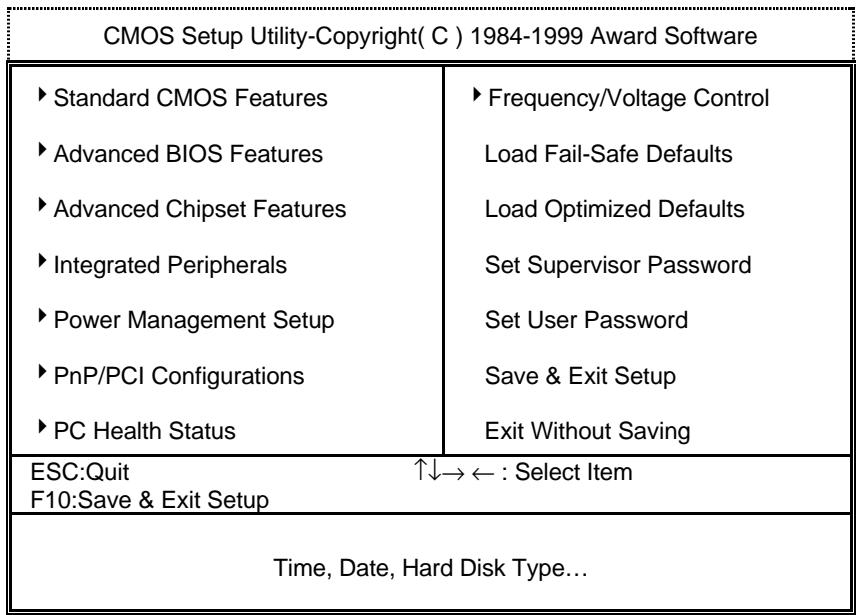
Figure 2: Main Menu
Standard CMOS Features
This setup page includes all the items in standard compatible BIOS.
Advanced BIOS Features
This setup page includes all the items of Award special enhanced features.
Advanced Chipset Features
This setup page includes all the items of chipset special features.
Integrated Peripherals
This setup page includes all onboard peripherals.
Power Management Setup
This setup page includes all the items of Green function features.
- PnP/PCI Configurations
This setup page includes all the configurations of PCI & PnP ISA resources.
PC Health Status
This setup page is the System auto detect Temperature, voltage , fan, speed.
Frequency/Voltage Control
This setup page is control CPU's clock and frequency ratio.
- Load Fail-Safe Defaults
Fail-Safe Defaults indicates the value of the system parameters which the system would be in safe configuration.
- Load Optimized Defaults
Optimized Defaults indicates the value of the system parameters which the system would be in best performance configuration.
Set Supervisor password
Change, set, or disable password. It allows you to limit access to the system and Setup, or just to Setup.
SetUserpassword
Change, set, or disable password. It allows you to limit access to the system.
- Save & Exit Setup
Save CMOS value settings to CMOS and exit setup.
- Exit Without Saving
Abandon all CMOS value changes and exit setup.
Standard CMOS Features
The items in Standard CMOS Setup Menu (Figure 3) are divided into 9 categories. Each category includes no, one or more than one setup items. Use the arrows to highlight the item and then use the
Figure 3: Standard CMOS Features
| CMOS Setup Utility-Copyright(C) 1984-1999 Award Software Standard CMOS Features | ||
| Date (mm:dd:yy) Time (hh:mm:ss) | Thu, Jan 7 1999 2 : 31 : 24 | Item Help |
| IDE Primary Master | Press Enter None | Menu Level |
| IDE Primary Slave | Press Enter None | Change the Day, month, Year and century |
| IDE Secondary Master | Press Enter None | |
| IDE Secondary Slave | Press Enter None | |
| Drive A | 1.44M, 3.5 in. | |
| Drive B | None | |
| Floppy 3 Mode Support | Disabled | |
| Video | EGA / VGA | |
| Halt On | All, But Keyboard | |
| Base Memory | 640K | |
| Extended Memory | 63488K | |
| Total Memory | 64512K | |
| ↑↓→←:Move Enter:Select +/-/PU/PD:Value F10:Save ESC:Exit F1:General Help F5:Previous Values F6:Fail-Safe Defaults F7:Optimized Defaults | ||
Date
The date format is <week> , <month> , <day> , <year> .
| week | The week, from Sun to Sat, determined by the BIOS and is display-only |
| month | The month, Jan. Through Dec. |
| day | The day, from 1 to 31 (or the maximum allowed in the month) |
| year | The year, from 1994 through 2079 |
Time
The times format in
IDE Primary Master, Slave / Secondary Master, Slave
The category identifies the types of hard disk from drive C to F that has been installed in the computer. There are two types: auto type, and manual type. Manual type is user-definable; Auto type which will automatically detect HDD type.
Note that the specifications of your drive must match with the drive table. The hard disk will not work properly if you enter improper information for this category.
If you select User Type, related information will be asked to enter to the following items. Enter the information directly from the keyboard and press
| CYLS. | Number of cylinders |
| HEADS | number of heads |
| PRECOMP | write precomp |
| LANDZONE | Landing zone |
| SECTORS | number of sectors |
If a hard disk has not been installed select NONE and press
Drive A type / Drive B type
The category identifies the types of floppy disk drive A or drive B that has been installed in the computer.
| None | No floppy drive installed |
| 360K, 5.25 in. | 5.25 inch PC-type standard drive; 360K byte capacity. |
| 1.2M, 5.25 in. | 5.25 inch AT-type high-density drive; 1.2M byte capacity (3.5 inch when 3 Mode is Enabled). |
| 720K, 3.5 in. | 3.5 inch double-sided drive; 720K byte capacity |
| 1.44M, 3.5 in. | 3.5 inch double-sided drive; 1.44M byte capacity. |
| 2.88M, 3.5 in. | 3.5 inch double-sided drive; 2.88M byte capacity. |
- Floppy 3 Mode Support (for Japan Area)
| Disabled | Normal Floppy Drive. |
| Drive A | Drive A is 3 mode Floppy Drive. |
| Drive B | Drive B is 3 mode Floppy Drive. |
| Both | Drive A & B are 3 mode Floppy Drives. |
Video
The category detects the type of adapter used for the primary system monitor that must match your video display card and monitor. Although secondary monitors are supported, you do not have to select the type in setup.
| EGA/VGA | Enhanced Graphics Adapter/Video Graphics Array. For EGA, VGA, SVGA, or PGA monitor adapters |
| CGA 40 | Color Graphics Adapter, power up in 40 column mode |
| CGA 80 | Color Graphics Adapter, power up in 80 column mode |
| MONO | Monochrome adapter, includes high resolution monochrome adapters |
- Halt on
The category determines whether the computer will stop if an error is detected during power up.
| NO Errors | The system boot will not stop for any error that may be detected and you will be prompted |
| All Errors | Whenever the BIOS detects a non-fatal error the system will be stopped |
| All, But Keyboard | The system boot will not stop for a keyboard error; it will stop for all other errors (Default value) |
| All, But Diskette | The system boot will not stop for a disk error; it will stop for all other errors |
| All, But Disk/Key | The system boot will not stop for a keyboard or disk error; it will stop for all other errors |
Memory
The category is display-only which is determined by POST (Power On Self Test) of the BIOS.
Base Memory
The POST of the BIOS will determine the amount of base (or conventional) memory installed in the system.
The value of the base memory is typically 512 K for systems with 512 K memory installed on the motherboard, or 640 K for systems with 640 K or more memory installed on the motherboard.
Extended Memory
The BIOS determines how much extended memory is present during the POST.
This is the amount of memory located above 1 MB in the CPU's memory address map.
Advanced BIOS Features
Figure 4: Advanced BIOS Features
| CMOS Setup Utility-Copyright(C) 1984-1999 Award Software Advanced BIOS Features | ||
| Virus Warning | Disabled | Item Help |
| CPU Cache | Enabled | |
| CPU L2 Cache ECC Checking | Disabled | Menu Level▲ |
| *Processor Number Feature | Enabled | Allows you to choose the VIRUS Warning feature |
| Quick Power On Self Test | Enabled | |
| First Boot Device | Floppy | For IDE Hard disk |
| Second Boot Device | HDD-0 | Boot sector |
| Third Boot Device | LS/ZIP | Protection. If this |
| Boot Other Device | Enabled | Function is enable |
| Swap Floppy Drive | Disabled | And someone |
| Boot Up Floppy Seek | Enabled | Attempt to write |
| Boot Up NumLock Status | On | Data into this area, BIOS will show |
| Gate A20 Option | Fast | A warning |
| Typematic Rate Setting | Disabled | Message on |
| Typematic Rate (Chars/Sec) | 6 | Screen and alarm beep |
| Typematic Delay (Msec) | 250 | |
| Security Option | Setup | |
| OS Select For DRAM >64MB | Non-OS2 | |
| HDD S.M.A.R.T. Capability | Disabled | |
| Report No FDD For WIN 95 | No | |
| ↑↓→←:Move Enter:Select +/-/PU/PD:Value F10:Save ESC:Exit F1:General Help F5:Previous Values F6:Fail-Safe Defaults F7:Optimized Defaults | ||
- System will detect automatically and show up when you install the Pentium III processor.
Virus Warning
If it is set to enable, the category will flash on the screen when there is any attempt to write to the boot sector or partition table of the hard disk drive. The system will halt and the following error message will appear in the mean time. You can run anti-virus program to locate the problem.
| Enabled | Activate automatically when the system boots up causing a warning message to appear when anything attempts to access the boot sector or hard disk partition table. |
| Disabled | No warning message to appear when anything attempts to access the boot sector or hard disk partition table. (Default value) |
CPU Cache
These two categories speed up memory access. However, it depends on CPU / chipset design.
| Enabled | Enable cache. (Default value) |
| Disabled | Disable cache. |
CPU L2 Cache ECC Checking
| Enabled | Enable CPU L2 Cache ECC Checking. |
| Disabled | Disable CPU L2 Cache ECC Checking. (Default value) |
Processor Number Feature
This item will show up when you install the Pentium III processor.
| Enabled | Pentium III Processor Number Feature. (Default value) |
| Disabled | Disable this function |
Quick Power On Self Test
This category speeds up Power On Self Test (POST) after you power on the computer. If it is set to Enable, BIOS will shorten or skip some check items during POST.
| Enabled | Enable quick POST. (Default value) |
| Disabled | Normal POST. |
- First / Second / Third Boot device
| Floppy | Select your boot device priority by Floppy. |
| LS/ZIP | Select your boot device priority by LS/ZIP. |
| HDD-0~3 | Select your boot device priority by HDD-0~3. |
| SCSI | Select your boot device priority by SCSI. |
| CDROM | Select your boot device priority by CDROM. |
| Disable | Disable this function. |
| LAN | Select your boot device priority by LAN. |
- Boot other device
| Enabled | Enabled select your boot device priority function. (Default value) |
| Disabled | Disabled this function |
Swap Floppy Drive
| Enabled | Floppy A & B will be swapped under DOS. |
| Disabled | Floppy A & B will be normal definition. (Default value) |
- Boot Up Floppy Seek
During POST, BIOS will determine the floppy disk drive installed is 40 or 80 tracks. 360 K type is 40 tracks 720 K, 1.2 M and 1.44 M are all 80 tracks.
| Enabled | BIOS searches for floppy disk drive to determine it is 40 or 80 tracks. Note that BIOS can not tell from 720 K, 1.2 M or 1.44 M drive type as they are all 80 tracks. (Default value) |
| Disabled | BIOS will not search for the type of floppy disk drive by track number. Note that there will not be any warning message if the drive installed is 360 K. |
- Boot Up NumLock Status
| On | Keypad is number keys. (Default value) |
| Off | Keypad is arrow keys. |
Gate A20 Option
| Normal | Set Gate A20 Option is Normal. |
| Fast | Set Gate A20 Option is Fast. (Default value) |
Typematic Rate Setting
| Enabled | Enable Keyboard Typematic rate setting. |
| Disabled | Disable Keyboard Typematic rate setting. (Default value) |
Typematic Rate (Chars / Sec.)
| 6-30 | Set the maximum Typematic rate from 6 chars. Per second to 30 characters. Per second. (Default value : 6) |
Typematic Delay (Msec.)
| 250-1000 | Set the time delay from first key to repeat the same key in to computer. (Default value : 250) |
Security Option
This category allows you to limit access to the system and Setup, or just to Setup.
| System | The system can not boot and can not access to Setup page will be denied if the correct password is not entered at the prompt. |
| Setup | The system will boot, but access to Setup will be denied if the correct password is not entered at the prompt. (Default value) |
OS Select For DRAM>64MB
| Non-OS2 | Using non-OS2 operating system. (Default value) |
| OS2 | Using OS2 operating system and DRAM>64MB. |
HDD S.M.A.R.T. Capability
| Enabled | Enabled HDD S.M.A.R.T. Capability. |
| Disabled | Disabled HDD S.M.A.R.T. Capability. (Default value) |
Report No FDD For WIN 95
| No | Assign IRQ6 For FDD. (Default value) |
| Yes | FDD Detect IRQ6 Automatically. |
Advanced Chipset Features
Figure 5: Advanced Chipset Features
| CMOS Setup Utility-Copyright( C ) 1984-1999 Award Software Advanced Chipset Features | ||
| SDRAM CAS Latency Time | Auto | Item Help |
| SDRAM Cycle Time Tras/Trc | 5/7 | |
| SDRAM RAS-to-CAS Delay | 2 | Menu Level ▶ |
| SDRAM RAS Precharge Time | 2 | |
| SDRAM Buffer Strength | Auto | |
| DRAM Page Closing Policy | Precharge Bank | |
| System BIOS Cacheable | Enabled | |
| Video BIOS Cacheable | Enabled | |
| Delayed Transaction | Disabled | |
| On-Chip Video Window Size | 64MB | |
| Local Memory Frequency | 100MHz | |
| * Onboard Display Cache Setting * | ||
| Initial Display Cache | Enabled | |
| Display Cache Timing | Auto | |
| ↑↓→←:Move Enter:Select +/-/PU/PD:Value F10:Save ESC:Exit F1:General Help F5:Previous Values F6:Fail-Safe Defaults F7:Optimized Defaults | ||
SDRAM CAS latency Time
| Auto | Set SDRAM CAS Latency Time to Auto. (Default value) |
| 3 | For 67 / 83 MHz SDRAM DIMM module. |
| 2 | For 100 MHz SDRAM DIMM module. |
SDRAM Cycle Time Tras/Trc
| 6/8 | Set DRAM Tras/Trc Cycle time is 6/8 SCLKs. |
| 5/7 | Set DRAM Tras/Trc Cycle time is 5/7 SCLKs. (Default value) |
SDRAM RAS-to-CAS delay
| 3 | Set SDRAM RAS-to-CAS delay 3 SCLKs. |
| 2 | Set SDRAM RAS-to-CAS delay 2 SCLKs. (Default value) |
SDRAM RAS Precharge
| 3 | Set SDRAM RAS Precharge is 3. |
| 2 | Set SDRAM RAS Precharge is 2. (Default value) |
SDRAM Buffer Strength
| Auto | Set SDRAM Buffer Strength is Auto. (Default Value) |
| Auto+1 | Set SDRAM Buffer Strength is Auto+1. |
| Auto-1 | Set SDRAM Buffer Strength is Auto-1. |
DRAM Page Closing Policy
| Precharge Bank | Closing Policy Precharge Bank. (Default value) |
| Precharge All | Closing Policy Precharge All. |
System BIOS Cacheable
| Enabled | Enable System BIOS Cacheable. (Default value) |
| Disabled | Disable System BIOS Cacheable. |
Video BIOS Cacheable
| Enabled | Enable video BIOS Cacheable. (Default value) |
| Disabled | Disable video BIOS Cacheable. |
- Delayed Transaction
| Disabled | Normal operation. (Default value) |
| Enabled | For slow speed ISA device in system. |
- On-Chip Video Window Size
| 32MB | Set Graphics Aperture Size to 32MB. |
| 64MB | Set Graphics Aperture Size to 64MB. (Default value) |
Local Memory Frequency (For 82810E)
| 100MHz | Set Local Memory Frequency to 100MHz. (Default value) |
| 133MHz | Set Local Memory Frequency to 133MHz. |
- Initialize Display Cache
| Disabled | Disabled Initialize Display Cache. |
| Enabled | Enabled Initialize Display Cache. (Default value) |
- Display Cache Timing
| Auto | Set Display Cache Timing to Auto. (Default value) |
| Fast | Set Display Cache Timing to Fast. |
| Normal | Set Display Cache Timing to Normal. |
Integrated Peripherals
| CMOS Setup Utility-Copyright(C) 1984-1999 Award Software Integrated Peripherals | ||
| On-Chip Primary PCI IDE | Enabled | Item Help |
| On-Chip Secondary PCI IDE | Enabled | |
| IDE Primary Master PIO | Auto | Menu Level ▶ |
| IDE Primary Slave PIO | Auto | |
| IDE Secondary Master PIO | Auto | |
| IDE Secondary Slave PIO | Auto | |
| IDE Primary Master UDMA | Auto | |
| IDE Primary Slave UDMA | Auto | |
| IDE Secondary Master UDMA | Auto | |
| IDE Secondary Slave UDMA | Auto | |
| USB Controller | Enabled | |
| USB Keyboard Support | Disabled | |
| Init Display First | PCI Slot | |
| AC97 Audio | Auto | |
| AC97 Modem | Auto | |
| IDE HDD Block Mode | Enabled | |
| POWER ON Function | BUTTON ONLY | |
| *KB Power ON Password | Enter | |
| Onboard FDC Controller | Enabled | |
| Onboard Serial Port 1 | Auto | |
| UART Mode Select | Normal | |
| *RxD, TxD Active | Hi,Lo | |
| *IR Transmittion delay | Enabled | |
| Onboard Parallel Port | 378/IRQ7 | |
| Parallel Port Mode | SPP | |
| *EPP Mode Select | EPP1.7 | |
| *ECP Mode Use DMA | 3 | |
| Game Port Address | 201 | |
| Midi Port Address | 330 | |
| *Midi Port IRQ | 10 | |
| ↑↓→←:Move Enter:Select +/-/PU/PD:Value F10:Save ESC:Exit F1:General Help F5:Previous Values F6:Fail-Safe Defaults F7:Optimized Defaults | ||
Figure 6: Integrated Peripherals
- On-Chip Primary PCI IDE
| Enabled | Enable onboard 1st channel IDE port. (Default value) |
| Disabled | Disable onboard 1st channel IDE port. |
- On-Chip Secondary PCI IDE
| Enabled | Enable onboard 2nd channel IDE port. (Default value) |
| Disabled | Disable onboard 2nd channel IDE port. |
IDE Primary Master PIO (for onboard IDE 1st channel)
| Auto | BIOS will automatically detect the IDE HDD Accessing mode. (Default value) |
| Mode0~4 | Manually set the IDE Accessing mode. |
IDE Primary Slave PIO (for onboard IDE 1st channel)
| Auto | BIOS will automatically detect the IDE HDD Accessing mode. (Default value) |
| Mode0~4 | Manually set the IDE Accessing mode. |
IDE Secondary Master PIO (for onboard IDE 2nd channel)
| Auto | BIOS will automatically detect the IDE HDD Accessing mode. (Default value) |
| Mode0~4 | Manually set the IDE Accessing mode. |
IDE Secondary Slave PIO (for onboard IDE 2nd channel)
| Auto | BIOS will automatically detect the IDE HDD Accessing mode. (Default value) |
| Mode0~4 | Manually set the IDE Accessing mode. |
IDE Primary Master UDMA
| Auto | BIOS will automatically detect the IDE HDD Accessing mode. (Default value) |
| Disabled | Disable UDMA function. |
IDE Primary Slave UDMA
| Auto | BIOS will automatically detect the IDE HDD Accessing mode. (Default value) |
| Disabled | Disable UDMA function. |
IDE Secondary Master UDMA
| Auto | BIOS will automatically detect the IDE HDD Accessing mode. (Default value) |
| Disabled | Disable UDMA function. |
IDE Secondary Slave UDMA
| Auto | BIOS will automatically detect the IDE HDD Accessing mode. (Default value) |
| Disabled | Disable UDMA function. |
USB Controller
| Enabled | Enable USB Controller. (Default value) |
| Disabled | Disable USB Controller. |
USB Keyboard Support
| Enabled | Enable USB Keyboard Support. |
| Disabled | Disable USB Keyboard Support. (Default value) |
- Init Display First
| PCI Slot | Set Init Display First to PCI Slot. (Default value) |
| Onboard | Set Init Display First to onboard AGP. |
AC'97 Audio
| Auto | BIOS will automatically detect onboard AC'97 Audio or YAMAHA 744 audio. (Default value) |
| Enabled | Enabled AC'97 Audio. |
| Disabled | Disabled AC'97 Audio. |
AC'97 Modem
| Auto | Bios will automatically detect onboard AC’97 Modem. ( Default value ) |
| Enabled | Enabled AC’97 Modem. |
| Disabled | Disabled AC’97 Modem. |
IDE HDD Block Mode
| Enabled | Enable IDE HDD Block Mode. (Default value) |
| Disabled | Disable IDE HDD Block Mode. |
- POWER ON Function
| Password | Enter from 1 to 5 characters to set the Keyboard Power On Password. |
| Mouse Left | Double click twice on PS/2 left bottom. |
| Mouse Right | Double click twice on PS/2 right bottom. |
| BUTTON ONLY | If your keyboard have “POWER Key” button, you can press the key to power on your system. (Default value) |
| Keyboard 98 | Windows 98 keyboard “Power” key. |
Onboard FDC Controller
| Enabled | Enable onboard FDC port. (Default value) |
| Disabled | Disable onboard FDC port. |
Onboard Serial Port 1
| Auto | BIOS will automatically setup the port 1 address. (Default value) |
| 3F8/IRQ4 | Enable onboard Serial port 1 and address is 3F8. |
| 2F8/IRQ3 | Enable onboard Serial port 1 and address is 2F8. |
| 3E8/IRQ4 | Enable onboard Serial port 1 and address is 3E8. |
| 2E8/IRQ3 | Enable onboard Serial port 1 and address is 2E8. |
| Disabled | Disable onboard Serial port 1. |
- UART Mode Select
(This item allows you to determine which Infra Red(IR) function of Onboard I/O chip)
| ASKIR | Onboard I/O chip supports ASKIR. |
| IrDA | Onboard I/O chip supports IrDA. |
| Normal | Onboard I/O chip supports Normal. (Default value) |
RxD,TxD Active
| Hi, Hi | RxD set Hi, TxD set Hi. |
| Hi, Lo | RxD set Hi, TxD set Lo. (Default value) |
| Lo, Hi | RxD set Lo,TxD set Hi. |
| Lo, Lo | RxD set Lo,TxD set Lo. |
IR Transmittion delay
| Enabled | Set IR Transmittion delay Enabled. (Default value) |
| Disabled | Set IR Transmittion delay Disabled. |
- Onboard Parallel port
| 378/IRQ7 | Enable onboard LPT port and address is 378/IRQ7. (Default value) |
| 278/IRQ5 | Enable onboard LPT port and address is 278/IRQ5. |
| Disabled | Disable onboard LPT port. |
| 3BC/IRQ7 | Enable onboard LPT port and address is 3BC/IRQ7. |
Parallel Port Mode
| SPP | Using Parallel port as Standard Parallel Port. (Default value) |
| EPP | Using Parallel port as Enhanced Parallel Port. |
| ECP | Using Parallel port as Extended Capabilities Port. |
| ECP+EPP | Using Parallel port as ECP & EPP mode. |
EPP Mode Select
| EPP 1.9 | Set EPP Mode Select is EPP 1.9. |
| EPP 1.7 | Set EPP Mode Select is EPP 1.7. (Default value) |
ECP Mode Use DMA
| 1 | Set ECP Mode Use DMA is 1. |
| 3 | Set ECP Mode Use DMA is 3. (Default value) |
Game Port Address
| Disabled | Disabled this function. |
| 201 | Set onboard game port is 201. (Default value) |
| 209 | Set onboard game port is 209. |
- Midi Port Address
| Disabled | Disabled On Board Midi Port. |
| 300 | Set On Board Midi Port is 300. |
| 330 | Set On Board Midi Port is 330. (Default value) |
- Midi Port IRQ
| 5 | Set 5 for Midi Port IRQ. |
| 10 | Set 10 for Midi Port IRQ. (Default value) |
Power Management Setup
Figure 7: Power Management Setup
| CMOS Setup Utility-Copyright( C ) 1984-1999 Award Software Power Management Setup | ||
| ACPI Suspend Type | S1(PowerOnSuspend) | Item Help |
| Power Management | User Define | |
| Video Off Method | DPMS | Menu Level ▶ |
| Video Off In Suspend | Yes | |
| Suspend Type | Stop Grant | |
| MODEM Use IRQ | 4 | |
| Suspend Mode | Disabled | |
| HDD Power Down | Disabled | |
| Soft-Off by PWR-BTTN | Instant-off | |
| Power LED in Suspend | Blinking | |
| AC BACK Function | Memory | |
| Wake-Up by PCI card | Enabled | |
| ModemRingOn/WakeOnLan | Enabled | |
| FAN Off In Suspend | Enabled | |
| USB KB/Mouse Wake From S3 | Disabled | |
| CPU Thermal-Throttling | 50% | |
| Resume by Alarm | Disabled | |
| * Date(of Month) Alarm | 0 | |
| * Time(hh:mm:ss) Alarm | 0 0 0 | |
| ** Reload Global Timer Events ** | ||
| Primary IDE 0 | Disabled | |
| Primary IDE 1 | Disabled | |
| Secondary IDE 0 | Disabled | |
| Secondary IDE 1 | Disabled | |
| FDD,COM,LPT Port | Enabled | |
| PCI PIQ[A-D]# | Enabled | |
| ↑↓→←:Move Enter:Select +/-/PU/PD:Value F10:Save ESC:Exit F1:General Help F5:Previous Values F6:Fail-Safe Defaults F7:Optimized Defaults | ||
ACPI Suspend Type
| S1(PowerOn Suspend) | Set ACPI Suspend type is S1. (Default value) |
| S3(Suspend to RAM) | Set ACPI Suspend type is S3. |
Power Management
| User Define | For configuring our own power management features. (Default value) |
| Min Saving | Enable Green function. |
| Max Saving | Disable Green function. |
Video off Method
| V/H SYNC+Blank | BIOS will turn off V/H-SYNC when gets into Green mode for Green monitor power saving. |
| Blank Screen | BIOS will only black monitor when gets into Green mode. |
| DPMS | BIOS will use DPMS Standard to control VGA card. (The Green type VGA card will turn off V/H-SYNC automatically.) (Default value) |
Video Off In Suspend
| Yes | Enabled video off in suspend. (Default value) |
| No | Disabled video off in suspend. |
- Suspend Type
| Stop Grant | Set Suspend type is stop grant. (Default value) |
| PwrOn Suspend | Set Suspend type is Power on suspend. |
MODEM Use IRQ
| NA | Set MODEM Use IRQ to NA. |
| 3 | Set MODEM Use IRQ to 3. |
| 4 | Set MODEM Use IRQ to 4. (Default value) |
| 5 | Set MODEM Use IRQ to 5. |
| 7 | Set MODEM Use IRQ to 7. |
| 9 | Set MODEM Use IRQ to 9. |
| 10 | Set MODEM Use IRQ to 10. |
| 11 | Set MODEM Use IRQ to 11. |
- Suspend Mode
| Disabled | Disable Suspend Mode. (Default value) |
| 1 min - 1 Hour | Setup the timer to enter Suspend Mode. |
HDD Power Down
| Disable | Disable HDD Power Down mode function. (Default value) |
| 1-15 mins. | Enable HDD Power Down mode between 1 to 15 mins. |
Soft-off by PWR-BTTN
| Instant-off | Soft switch ON/OFF for POWER ON/OFF. (Default value) |
| Delay 4 Sec. | Soft switch ON 4sec. for POWER OFF. |
Power LED in Suspend
| Blinking | Set Power LED in Suspend at Blinking mode. (Default value) |
| On | Set Power LED in Suspend at On mode. |
| Off/Dual | Set Power LED in Suspend at Off/Dual color mode. |
AC Back Function
| Memory | This function depends on computer status. (Default value) |
| Soft-Off | Set System Soft-Off Status. |
| Full-On | Set System Full-On Status. |
Wake-Up by PCI card
| Disabled | Disabled this function. |
| Enabled | Enabled wake-up by PCI card. (Default value) |
ModemRingOn / WakeOnLan
| Disabled | Disable these functions. |
| Enabled | Enable these functions. (Default value) |
FAN Off In Suspend
| Disabled | Disable this function. |
| Enabled | Stop CPU FAN when entering Suspend mode. (Default value) |
USB KB/Mouse Wake From S3
| Disabled | Disabled this function. (Default value) |
| Enabled | Enabled USB KB/Mouse Wake From S3 function. |
CPU Thermal-Throttling
| 87.5% | Monitor CPU Temp. will cause system slow down CPU Duty Cycle to 87.5%. |
| 75.0% | Monitor CPU Temp. will cause system slow down CPU Duty Cycle to 75.0%. |
| 62.5% | Monitor CPU Temp. will cause system slow down CPU Duty Cycle to 62.5%. |
| 50.0% | Monitor CPU Temp. will cause system slow down CPU Duty Cycle to 50.0%. (Default value) |
| 37.5% | Monitor CPU Temp. will cause system slow down CPU Duty Cycle to 37.5%. |
| 25.0% | Monitor CPU Temp. will cause system slow down CPU Duty Cycle to 25.0%. |
| 12.5% | Monitor CPU Temp. will cause system slow down CPU Duty Cycle to 12.5%. |
Resume by Alarm
| Disabled | Disable this function. (Default value) |
| Enabled | Enable alarm function to POWER ON system. |
If the default value is Enabled.
| Date ( of Month) Alarm : | 0~31 |
| Time ( hh: mm: ss) Alarm : | (0~23) : (0~59) : (0~59) |
Primary IDE 0/1
| Disabled | Disable this function. (Default value) |
| Enabled | Enable monitor Primary IDE 0/1 for Green event. |
Secondary IDE 0/1
| Disabled | Disable this function. (Default value) |
| Enabled | Enable monitor Secondary IDE 0/1 for Green event. |
FDD/COM/LPT Port
| Disabled | Disable this function. |
| Enabled | Enable monitor FDC/COM/LPT for Green event. (Default value) |
PCIPIRQ[A-D]#
| Enabled | Monitor PCI PIQ[A-D] IRQ Active. (Default value) |
| Disabled | Ignore PCI PIQ[A-D] IRQ Active. |
PnP/PCI Configurations
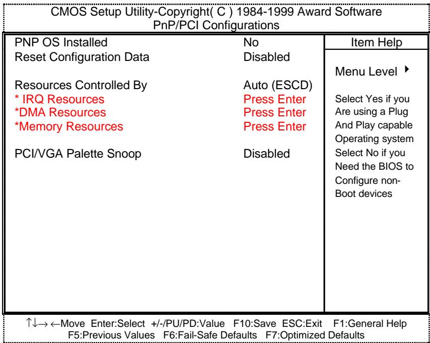
Figure 8: PnP/PCI Configurations
PNP OS Installed
| Yes | Enable PNP OS Installed function. |
| No | Disable PNP OS Installed function. (Default value) |
- Reset Configuration Data
| Disabled | Disable this function. (Default value) |
| ESCD | Clear PnP information in ESCD. |
| DMI | Update Desktop Management Information data. |
| Both | Clear PnP information in ESCD & update DMI data. |
Resources Controlled by
| Manual | User can set the PnP resource (I/O Address, IRQ & DMA channels) used by legacy ISA DEVICE. |
| Auto (ESCD) | BIOS automatically use these PnP rescuers. (Default value) |
IRQ (3,4,5,7,9,10,11,12,14,15),DMA(0,1,3,5,6,7) assigned to (Legacy ISA or "PCI/ISA PnP)
| Legacy ISA | The resource is used by Legacy ISA device. |
| PCI/ISA PnP | The resource is used by PCI/ISA PnP device (PCI or ISA). |
Reserved Memory Base
| N/A | Disable the MEM. block using. (Default value) |
| C800 ~ DC00 | Select the MEM. block starting address. |
PCI/VGA Palette Snoop
| Enabled | For having Video Card on ISA Bus and VGA Card on PCI Bus. |
| Disabled | For VGA Card only. (Default value) |
PC Health Status
Figure 9: PC Health Status
| CMOS Setup Utility-Copyright(C) 1984-1999 Award Software PC Health Status | ||
| Reset Case Open Status | Disabled | Item Help |
| Case Opened | Yes | Menu Level ▶ |
| Current CPU Temperature | 47°C/116°F | |
| CPU FAN Speed | 5443 RPM | |
| Power FAN Speed | 0 RPM | |
| System FAN speed | 0 RPM | |
| VCORE | 1.936 V | |
| VGTL | 1.424 V | |
| VCC3 | 3.264 V | |
| +5V | 4.730 V | |
| +12V | 11.648 V | |
| -12V | -11.210 V | |
| -5V | -4.856 V | |
| VBAT | 2.880 V | |
| 5VSB | 4.784 V | |
| CPU Warning Temperature | 70°C/158°F | |
| Shutdown Temperature | 75°C/167°F | |
| CPU FAN Fail Alarm | Disabled | |
| Power FAN Fail Alarm | Disabled | |
| System FAN Fail Alarm | Disabled | |
| ↑↓→←Move Enter:Select +/-/PU/PD:Value F10:Save ESC:Exit F1:General Help F5:Previous Values F6:Fail-Safe Defaults F7:Optimized Defaults | ||
- Reset Case Open Status
Case Opened
If the case is closed, "Case Opened" will show "No".
If the case have been opened, "Case Opened" will show "Yes".
If you want to reset "Case Opened" value, set "Reset Case Open Status"
to "Enabled" and save CMOS, your computer will restart.
Current CPU Temperature (^ / ^)
Detect CPU Temp. automatically.
CPU FAN / Power FAN / System FAN Speed (RPM)
Detect Fan speed status automatically.
- Current Voltage (V) VCORE / VGTL/ VCC3 / -12V / -5V / 5VSB /VBAT
Detect system's voltage status automatically.
CPU Warning Temperature (^ / ^)
| 65°C / 149°F | Monitor CPU Temp. at 65°C / 149°F. |
| 70°C / 158°F | Monitor CPU Temp. at 70°C / 158°F. (Default value) |
| 75°C / 167°F | Monitor CPU Temp. at 75°C / 167°F. |
| Disabled | Disabled this function. |
- Shutdown Temp. (^ / ^)
(This function will be effective only for the operating systems that support ACPI Function.)
| Disabled | Normal Operation |
| 65°C / 149°F | Monitor CPU Temp. at 65°C / 149°F, if Temp. > 65°C / 149°F system will automatically power off . |
| 70°C / 158°F | Monitor CPU Temp. at 70°C / 158°F, if Temp. > 70°C / 158°F system will automatically power off . |
| 75°C / 167°F | Monitor CPU Temp. at 75°C / 167°F, if Temp. > 75°C / 167°F system will automatically power off . (Default value) |
Fan Fail Alarm
CPU / Power / System
| Disabled | Fan Fail Alarm Function Disabled. (Default value) |
| Enabled | Fan Fail Alarm Function Enabled. |
Frequency/Voltage Control
Figure 10: Frequency/Voltage Control
| CMOS Setup Utility-Copyright( C ) 1984-1999 Award Software Frequency/Voltage Control | ||
| Auto Detect DIMM/PCI Clk Enabled | Item Help | |
| Spread Spectrum Disabled | ||
| CPU Type INTEL(R) CELERON 200 | Menu Level ▶ | |
| ↑↓→←Move Enter:Select +/-/PU/PD:Value F10:Save ESC:Exit F1:General Help F5:Previous Values F6:Fail-Safe Defaults F7:Optimized Defaults | ||
- Auto Detect DIMM/PCI Clk
| Disabled | Disabled Auto Detect DIMM/PCI Clk. |
| Enabled | Enabled Auto Detect DIMM/PCI Clk. (Default value) |
- Spread Spectrum
CPU Type INTEL(R) CELERON
| Disabled | Disabled this function. (Default value) |
| 0.25% (Cntr) | Set Spread Spectrum to 0.25%(Center spread). |
| 0.50%(Down) | Set Spread Spectrum to 0.50%(Down spread). |
- System Bus Speed :66MHz
| 200 / 233 / 266 / 300 / 333 / 366 / 400 / 433 / 466 / 500 / 533 |
- System Bus Speed : 100MHz
| 300 / 350 / 400 / 450 / 500 / 550 / 600 / 650 / 700 / 750 / 800 |
- System Bus Speed : 133MHz
| 400 / 466 / 533 / 600 / 666 / 733 / 800 / 866 / 933 / 1000 / 1066 |
Load Fail-Safe Defaults
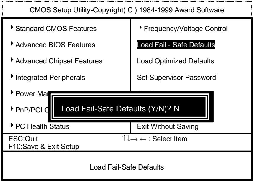
Figure 11: Load Fail-Safe Defaults
- Load Fail-Safe Defaults
Fail-Safe defaults contain the most appropriate values of the system parameters that allow minimum system performance.
Load Optimized Defaults
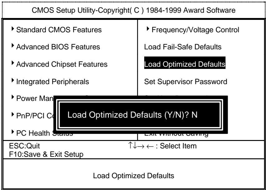
Figure 12: Load Optimized Defaults
- Load Optimized Defaults
Selecting this field loads the factory defaults for BIOS and Chipset Features which the system automatically detects.
Set Supervisor / User Password
When you select this function, the following message will appear at the center of the screen to assist you in creating a password.
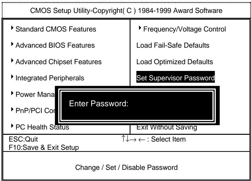
Figure 13: Password Setting
Type the password, up to eight characters, and press
To disable password, just press
If you select System at Security Option in BIOS Features Setup Menu, you will be prompted for the password every time the system is rebooted or any time you try to enter Setup Menu. If you select Setup at Security Option in BIOS Features Setup Menu, you will be prompted only when you try to enter Setup.
Save & Exit Setup

Figure 14: Save & Exit Setup
Type "Y" will quit the Setup Utility and save the user setup value to RTC CMOS.
Type "N" will return to Setup Utility.
Exit Without Saving
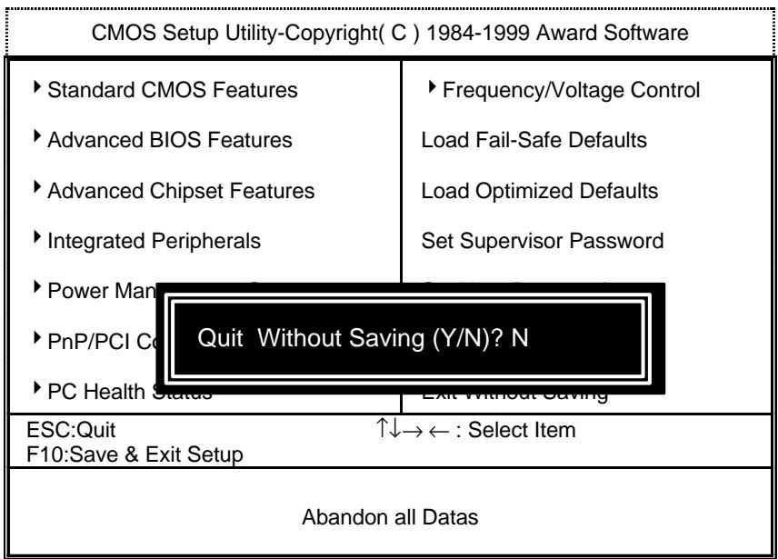
Figure 15: Exit Without Saving
Type "Y" will quit the Setup Utility without saving to RTC CMOS.
Type "N" will return to Setup Utility.
Appendix
Appendix A: Onboard Driver Installation Procedure
(In this manual, we assume that your CD-ROM Drive letter to be Drive D: )
Please reference IUCD CD directory D: \ Manual \ Whitney 810.pdf
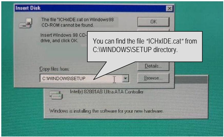
Appendix B:810 INF update utility can't find ICHxIDE.cat file automatically
- After the installation is of Winodws98 is completed, run the "Setup.exe" of INF update utility.
- System restarts.
- System starts to recognize every new component.
- System will stop and prompt users to specify the location of "ICHxIDE.cat" file.
- The system will not find the location of ICHxIDE.cat automatically.
Resolution :
Appendix C: AU8810 Driver Installation
A. DRIVER INSTALLATION
If you have older drivers in your system, please uninstall them first as described in Section C below.
- Power on the system, placing the "Intel chipset Series Mainboard Utility CD" in the CD-ROM drive.
- During the load process, Windows 95/98 should detect the Vortex PCI board and display a message such as "New Hardware Found". If Windows prompts you for the drivers of the "PCI Multimedia Audio Device", then select "Driver Disk Provided by Manufacturer" Select the Vortex CD-ROM's directory.
Note: Some Windows 95 versions (OSR2) do not show this prompt. Instead, they ask whether to search the diskette and CD-ROM drives for the appropriate drivers.
Installed drivers may include Vortex PCI audio, Vortex wavetable, Vortex mixer, DOS modem port, Vortex gameport interface, Vortex MPU401 interface, and Vortex Sound Blaster emulation.
Depending on the version of Windows 95 and the configuration of the system, you may be prompted to provide several file locations. Here are the CD-ROMs and directory locations for which you may be prompted:
Vortex Installation & Driver Disk \aurealwin9X
Windows 95/98 Installation Disk \aureal\win9X
Microsoft DirectX \Utility\directx\dxsetup
Vortex Application Setup \aureal\win9X
PCI Multifunction Audio Device \aureal\win9X
B. UNINSTALLING WINDOWS 95/98 DRIVERS
To uninstall the Vortex software, you can use the following procedure:
-
Open to the Windows 95/98 Device Manager (right-click on "My Computer" and select "Properties").
-
Open the "Multifunction Adapters" tree and select "Vortex Multifunction PCI Platform"
-
Press the "Remove" button at the bottom of the Device Manager window pane.
-
The drivers are now removed from memory, but are still on the hard disk. To delete the files from the hard disk:
a. Open the Windows 95/98 control panel's "Add/Remove Programs" applet.
b. To remove the drivers, double-click "Areal Vortex". A Vortex uninstaller application starts.
c. To remove the demo applications, double-click "Aureal Vortex Applications". There is no need to reboot the computer.
For Technical Support please contact your board manufacturer.
Areal. A3D, A3D-I, A3D-Interactive, and the Aureal logo are trademarks and Vortex is a registered trademark of Aureal Semiconductor Inc.
All other trademarks are owned their respective owners.
Appendix D:BIOS Flash Procedure
BIOS update procedure:
Please check your BIOS vendor (AMI or AWARD) on the motherboard.
It is recommended you copy the AWDFlash.exe or AMIFlash.exe in driver CD (D:>Utility\BIOSFlash) and the BIOS binary files into the directory you made in your hard disk. i ie:C:>Utility (C: >Utility: denotes the driver and the directory where you put the flash utilities and BIOS file in.)j
- Restart your computer into MS-DOS mode or command prompt only for Win95/98, go into the directory where the new BIOS file are located use the utility AWDFlash.exe or AMIFlash.exe to update the BIOS.
Type the following command once you have enter the directory where all the files are located C:\utility\AWDFlash or AMIFlash
✓ Once the process is finished, reboot the system
Note: Please download the newest BIOS from our website (www.gigabyte.com.tw) or contact your local dealer for the file.
Appendix E: Acronyms
| Acor. | Meaning |
| ACPI | Advanced configuration and power interface |
| POST | Power-on self test |
| LAN | Local area network |
| ECP | Extended capabilities port |
| APM | Advanced power management |
| DMA | Direct memory access |
| MHz | Megahertz |
| ESCD | Extended system configuration data |
| CPU | Central processing unit |
| SMP | Symmetric multi-processing |
| USB | Universal serial bus |
| OS | Operating System |
| ECC | Error checking and correcting |
| IDE | Integrated dual channel enhanced |
| SCI | Special circumstance instructions |
| LBA | Logical block addressing |
| EMC | Electromagnetic compatibility |
| BIOS | Basic input / output system |
| SMI | System management interrupt |
| IRQ | Interrupt request |
| NIC | Network interface card |
| A.G.P. | Accelerated graphics port |
| S.E.C.C. | Single edge contact cartridge |
| LED | Light emitting diode |
| EPP | Enhanced parallel port |
| CMOS | Complementary metal oxide semiconductor |
| I/O | Input / Output |
| ESD | Electrostatic DISCHARGE |
| OEM | Original equipment manufacturer |
| SRAM | Static random access memory |
| VID | Voltage ID |
| DMI | Desktop Management Interface |
| MIDI | Musical interface digital interface |
| IOAPIC | Input Output Advanced Programmable Input Controller |
| DIMM | Dual inline memory module |
| DRAM | Dynamic random access memory |
| PAC | PCI A.G.P. controller |
| AMR | Audio Modem Riser |
To be continued
| Acor. | Meaning |
| PCI | Peripheral component interconnect |
| RIMM | Rambus In-line Memory Module |
| DRM | Dual retention mechanism |
| ISA | Industry standard architecture |
| CRIMM | Continuity RIMM |
- FCC Compliance Statement:
- Declaration of Conformity
- G.B.T. Technology Trading GmbH
- Ausschlager Weg 41, 1F, 20537 Hamburg, Germany
- Mother Board
- The manufacturer also declares the conformity of above mentioned product with the actual required safety standards in accordance with LVD 73/23 EEC
- Manufacturer/Importer
- 6WFZ7 Series
- Intel® 810 Socket 370 Motherboard
- USER'S MANUAL
- How This Manual Is Organized
- Item Checklist
- 6WFZ7 Series Motherboard Layout
- CPU Speed Setup
- Connectors
- COM A / VGA / LPT Port
- Game & Audio Port
- PS/2 Keyboard & PS/2 Mouse Connector
- CPU Cooling FAN Power Connector
- Power Cooling FAN Power Connector
- System Cooling FAN Power Connector
- IDE1(Primary), IDE2 (Secondary) Port
- USB Port
- Front Phone+MIC
- IR
- J7 : CD Audio Line In
- JP4: TEL (The connector is for modem with internal voice connector)
- JP7:AUXIN
- J10: Ring Power On (Internal Modem Card Wake Up)
- Panel and Jumper Definition
- JP21: Rear USB Device Wake up Selection (USB Connector → CN2)
- JP2:PS/2 Keyboard Power On
- JP6 : Top Block Lock
- JP9 : Onboard Sound Function Selection (Optional)
- JP14 : Timeout Reboot Function
- JP16 : Case Open
- JP17: Safe mode/Recovery/Normal
- JP18 : Clear CMOS Function
- J13: Buzzer Enable (Optional)
- JP20:STR Function Selection
- JP22: Front USB Device Wake up Function (USB Port → J9)
- JP23 : Onboard LAN Wake up Function(Optional)
- BAT1: Battery
- Performance List
- Block Diagram
- Suspend to RAM Installation
- A.1 Introduce STR function:
- A.2 STR function Installation
- Setup with Windows 98 CD:
- Step 2:
- Step 3:
- A.3 How to put your system into STR mode?
- Step 4:
- A.4 How to recover from the STR sleep mode?
- A.5 Notices :
- Memory Installation
- BIOS Setup
- ENTERING SETUP
- CONTROL KEYS
- GETTING HELP
- Main Menu
- Status Page Setup Menu / Option Page Setup Menu
- The Main Menu
- Standard CMOS Features
- Date
- Time
- IDE Primary Master, Slave / Secondary Master, Slave
- Drive A type / Drive B type
- Video
- - Halt on
- Memory
- Base Memory
- Extended Memory
- Advanced BIOS Features
- Virus Warning
- CPU Cache
- CPU L2 Cache ECC Checking
- Processor Number Feature
- Quick Power On Self Test
- - First / Second / Third Boot device
- - Boot other device
- Swap Floppy Drive
- - Boot Up Floppy Seek
- - Boot Up NumLock Status
- Gate A20 Option
- Typematic Rate Setting
- Typematic Rate (Chars / Sec.)
- Typematic Delay (Msec.)
- Security Option
- OS Select For DRAM>64MB
- HDD S.M.A.R.T. Capability
- Report No FDD For WIN 95
- Advanced Chipset Features
- SDRAM CAS latency Time
- SDRAM Cycle Time Tras/Trc
- SDRAM RAS-to-CAS delay
- Integrated Peripherals
- - POWER ON Function
- Onboard FDC Controller
- Onboard Serial Port 1
- - UART Mode Select
- RxD,TxD Active
- IR Transmittion delay
- Power Management Setup
- PnP/PCI Configurations
- PC Health Status
- Frequency/Voltage Control
- Load Fail-Safe Defaults
- - Load Fail-Safe Defaults
- Load Optimized Defaults
- - Load Optimized Defaults
- Set Supervisor / User Password
- Save & Exit Setup
- Exit Without Saving
- Appendix
- Appendix A: Onboard Driver Installation Procedure
- Appendix B:810 INF update utility can't find ICHxIDE.cat file automatically
- Resolution :
- Appendix C: AU8810 Driver Installation
- DRIVER INSTALLATION
- UNINSTALLING WINDOWS 95/98 DRIVERS
- Appendix D:BIOS Flash Procedure
Marque : GIGABYTE
Modèle : GA-6WFZ7-E
Catégorie : Équipement électronique