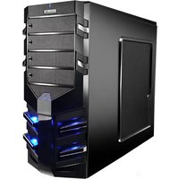
Sumo α - Unite Centrale GIGABYTE - Notice d'utilisation et mode d'emploi gratuit
Retrouvez gratuitement la notice de l'appareil Sumo α GIGABYTE au format PDF.


| Type de produit | Unité centrale (PC de bureau) |
| Marque | Gigabyte |
| Modèle | Sumo α |
| Dimensions (L x H x P) | Environ 200 x 450 x 480 mm |
| Poids | Environ 10 kg |
| Alimentation | Bloc d'alimentation interne 500 W (80+ Bronze) |
| Processeur supporté | Intel Core i5/i7 ou AMD Ryzen 5/7 |
| Mémoire RAM maximale | 32 Go (DDR4) |
| Stockage interne | SSD 512 Go + HDD 1 To |
| Carte graphique | NVIDIA GeForce GTX 1660 ou équivalent |
| Système d'exploitation | Windows 10 Famille (préinstallé) |
| Connectivité | Wi-Fi 6, Bluetooth 5.0, Ethernet Gigabit |
| Ports avant | 2x USB 3.0, 1x USB-C, prise casque/micro |
| Ports arrière | 4x USB 3.0, 2x USB 2.0, HDMI, DisplayPort, RJ45, audio |
| Refroidissement | Ventilateur processeur + 2 ventilateurs de boîtier |
| Niveau sonore | Environ 25 dB en mode veille, 35 dB en charge |
| Entretien et nettoyage | Dépoussiérage régulier des grilles et ventilateurs avec un chiffon doux |
| Sécurité | Antivol Kensington, mot de passe BIOS |
| Pièces détachées et réparabilité | RAM, SSD, HDD, carte graphique sont remplaçables par l'utilisateur |
| Garantie | 2 ans (pièces et main-d'œuvre) |
FOIRE AUX QUESTIONS - Sumo α GIGABYTE
Questions des utilisateurs sur Sumo α GIGABYTE
0 question sur cet appareil. Repondez a celles que vous connaissez ou posez la votre.
Poser une nouvelle question sur cet appareil
Téléchargez la notice de votre Unite Centrale au format PDF gratuitement ! Retrouvez votre notice Sumo α - GIGABYTE et reprennez votre appareil électronique en main. Sur cette page sont publiés tous les documents nécessaires à l'utilisation de votre appareil Sumo α de la marque GIGABYTE.
MODE D'EMPLOI Sumo α GIGABYTE
GIGABYTE™
Product is not warranted if the product is modified, altered or repaired without authorization by GIGABYTE. Specifications and pictures are to change without notice. Different motherboards have different installation areas specifications, screw holes and connectors. For detailed instructions, please refer to the motherboard user manual supplied by the motherboard manufacturer.
Casing's Internal Structure

Accessory Box
(Refer to the figures below for the attachments in the accessory box)


PSU securing screw x 4
A/B securing screw x 9
Copper standoff x 9
FAN securing screw x 4
Thrumb screw x 4
Cable Kit


Step 1. Removal of Front Panel

Step 2. Installation of Power Supply
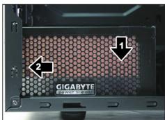
↓

Step 3. Installation of Motherboard
| Motherboard | Code name | Motherboard screw | Case copper post |
| ATX | A1-A9 | 9 | 9 |
| Micro ATX | U1-U8 | 8 | 8 |
| Flex ATX | F1-F6 | 6 | 6 |
| Mini ITX | B1-B4 | 4 | 4 |

Step 5. Installation of Add-on Card
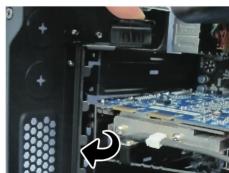
↓

Step 6. Installation of 5.25" External Driver Bay


Step 7. Installation of 3.5" Internal Driver Bay
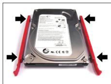
↓

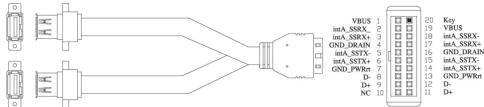
Step 4. Installation of Front I/O


USB 3.0
↓
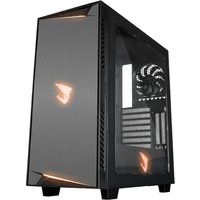
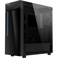
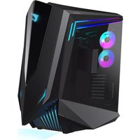
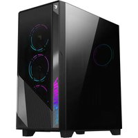
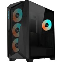
Marque : GIGABYTE
Modèle : Sumo α
Catégorie : Unite Centrale