
SPR876RAGH - Four encastrable SMEG - Notice d'utilisation et mode d'emploi gratuit
Retrouvez gratuitement la notice de l'appareil SPR876RAGH SMEG au format PDF.

| Marque | SMEG |
| Modèle | SPR876RAGH |
| Type de produit | Table de cuisson gaz encastrable |
| Alimentation gaz | Préréglée pour gaz naturel G20 (20 mbar), adaptable GPL G30/G31 (28/37 mbar) et gaz de ville G110 (8 mbar) |
| Alimentation électrique | Monophasé, câble H05V2V2-F 3×0,75 mm² |
| Nombre de brûleurs | 7 (auxiliaire, semi-rapide, moyen rapide, grand rapide, ultra-rapide triple couronne, ultra-rapide double couronne, poisson) |
| Allumage | Électronique intégré |
| Sécurité | Thermocouple sur chaque brûleur (arrêt automatique du gaz en cas d'extinction) |
| Matériau de la surface | Acier inoxydable |
| Nettoyage | Produits non abrasifs, éponge douce, pas de nettoyeur vapeur |
| Grilles | Amovibles, lavage à la main (pas au lave-vaisselle) |
| Couronnes et brûleurs | Démontables, nettoyage avec détergent doux |
| Adaptation gaz | Injecteurs fournis, réglage air primaire, joint d'étanchéité fourni |
| Raccordement gaz | Filetage 1/2" ISO 228-1, tuyau cuivre rigide ou acier flexible |
| Raccordement électrique | Disjoncteur multipolaire à ouverture ≥3 mm, prise accessible |
| Dimensions de découpe | Voir schéma dans la notice (distance minimale 50 mm du bord arrière) |
| Distance par rapport aux murs | ≥145 mm des parois latérales, ≥750 mm au-dessus d'une étagère |
| Plaque à griller | Utilisation possible avec précaution (max 45 minutes) |
| Diamètres de casseroles | De 7 cm (auxiliaire) à 28 cm (triple couronne) |
| Pays de destination | Symboles sur la couverture du manuel |
FOIRE AUX QUESTIONS - SPR876RAGH SMEG
Questions des utilisateurs sur SPR876RAGH SMEG
0 question sur cet appareil. Repondez a celles que vous connaissez ou posez la votre.
Poser une nouvelle question sur cet appareil
Téléchargez la notice de votre Four encastrable au format PDF gratuitement ! Retrouvez votre notice SPR876RAGH - SMEG et reprennez votre appareil électronique en main. Sur cette page sont publiés tous les documents nécessaires à l'utilisation de votre appareil SPR876RAGH de la marque SMEG.
MODE D'EMPLOI SPR876RAGH SMEG
Contents
- INSTRUCTIONS FOR USE 26
- SAFETY PRECAUTIONS 28
- ENVIRONMENTAL RESPONSIBILITY 30
- USING THE HOB 31
- CLEANING AND MAINTENANCE 33
- POSITIONING IN THE COUNTER TOP 36
- ELECTRICAL CONNECTION 38
- GAS CONNECTION 39
- ADAPTATION TO DIFFERENT TYPES OF GAS 41
THESE INSTRUCTIONS ARE VALID ONLY FOR THE DESTINATION COUNTRIES WHOSE IDENTIFYING SYMBOLS ARE INCLUDED ON THE COVER OF THIS MANUAL.

INSTRUCTIONS FOR THE USER: these contain user advice, the description of the controls and the correct procedures for cleaning and maintenance of the appliance.

INSTRUCTIONS FOR THE INSTALLER: these are intended for the qualified technician who must install the appliance, set it functioning and carry out an inspection test.
1. INSTRUCTIONS FOR USE

THIS MANUAL IS AN INTEGRAL PART OF THE APPLIANCE. IT MUST BE KEPT IN ITS ENTIRETY AND IN AN ACCESSIBLE PLACE FOR THE WHOLE WORKING LIFE OF THE COOKING HOB. WE ADVISE YOU TO READ THIS MANUAL AND ALL THE INFORMATION IT CONTAINS CAREFULLY BEFORE USING THE HOB. ALSO KEEP THE SERIES OF NOZZLES PROVIDED. INSTALLATION MUST BE CARRIED OUT BY QUALIFIED PERSONNEL IN ACCORDANCE WITH THE REGULATIONS IN FORCE. THIS APPLIANCE IS INTENDED FOR HOUSEHOLD USE AND COMPLIES WITH THE EEC DIRECTIVES CURRENTLY IN FORCE. THE APPLIANCE HAS BEEN BUILT TO CARRY OUT THE FOLLOWING FUNCTIONS: COOKING AND HEATING FOODS; ALL OTHER USES ARE TO BE CONSIDERED IMPROPER.
THE MANUFACTURER CANNOT BE HELD LIABLE FOR USE OTHER THAN AS INDICATED.

IF THE APPLIANCE IS INSTALLED ON BOATS OR IN CARAVANS, DO NOT USE IT AS A ROOM HEATER.

DO NOT USE THIS APPLIANCE FOR HEATING ROOMS.

THIS APPLIANCE IS MARKED ACCORDING TO EUROPEAN DIRECTIVE 2002/96/EC ON WASTE ELECTRICAL AND ELECTRONIC EQUIPMENT (WEEE).
THIS DIRECTIVE DETERMINES THE STANDARDS FOR THE COLLECTION AND RECYCLING OF WASTE ELECTRICAL AND ELECTRONIC EQUIPMENT APPLICABLE THROUGHOUT THE EUROPEAN UNION.

BEFORE THE APPLIANCE IS PUT INTO OPERATION, ALL PROTECTIVE FILMS MUST BE REMOVED.

SUITABLE HEAT-PROOF GLOVES SHOULD BE WORN FOR ALL OPERATIONS.

DO NOT USE STEEL SPONGES AND SHARP SCRAPERS AS THEY WILL DAMAGE THE SURFACE.
USE NORMAL NON-ABRASIVE PRODUCTS, INCLUDING WOODEN OR PLASTIC UTENSILS IF NECESSARY. RINSE THOROUGHLY AND DRY USING A SOFT CLOTH OR A MICROFIBRE CLOTH.


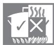
DO NOT LEAVE THE APPLIANCE UNATTENDED DURING COOKING OPERATIONS WHERE FATS OR OILS COULD BE RELEASED.
FATS AND OILS MAY CATCH FIRE.

ALWAYS CHECK THAT THE CONTROL KNOBS ARE IN THE (OFF) POSITION WHEN YOU FINISH USING THE HOB.
NEVER PLACE PANS WITH BOTTOMS WHICH ARE NOT PERFECTLY FLAT AND SMOOTH ON THE COOKING HOB RACKS.

NEVER USE CONTAINERS WHICH PROJECT BEYOND THE OUTSIDE EDGE OF THE HOB.
2. SAFETY PRECAUTIONS
REFER TO THE INSTALLATION INSTRUCTIONS FOR THE SAFETY REGULATIONS FOR ELECTRIC OR GAS APPLIANCES AND VENTILATION FUNCTIONS.
IN YOUR INTERESTS AND FOR YOUR SAFETY IT HAS BEEN ESTABLISHED BY LAW THAT THE INSTALLATION AND SERVICING OF ALL ELECTRICAL APPLIANCES IS TO BE CARRIED OUT BY QUALIFIED PERSONNEL IN ACCORDANCE WITH THE REGULATIONS IN FORCE.
OUR APPROVED INSTALLERS GUARANTEE A SATISFACTORY JOB.
GAS OR ELECTRICAL APPLIANCES MUST ALWAYS BE DISCONNECTED BY SUITABLY SKILLED PEOPLE.

BEFORE CONNECTING THE APPLIANCE TO THE POWER GRID, CHECK THE DATA ON THE PLATE AGAINST THE DATA FOR THE GRID ITSELF.
THE IDENTIFICATION PLATE CONTAINING THE TECHNICAL DATA, SERIAL NUMBER AND BRAND NAME IS IN A VISIBLE POSITION UNDER THE CASING.
DO NOT REMOVE THE PLATE ON THE CASING FOR ANY REASON.
BEFORE CONNECTING THE APPLIANCE,ENSURE THAT IT IS SET TO THE TYPE OF GAS THAT IT WILL BE SUPPLIED WITH, CHECKING THE LABEL APPLIED UNDER THE CASING.

BEFORE CARRYING OUT INSTALLATION/MAINTENANCE WORK, MAKE SURE THAT THE APPLIANCE IS NOT CONNECTED TO THE POWER GRID.
THE PLUG TO BE CONNECTED TO THE POWER SUPPLY CABLE AND ITS SOCKET MUST BE OF THE SAME TYPE AND CONFORM TO THE REGULATIONS IN FORCE. THE SOCKET MUST BE ACCESSIBLE AFTER THE APPLIANCE HAS BEEN BUILT IN. NEVER DISCONNECT THE PLUG BY PULLING ON THE CABLE.

IF THE POWER SUPPLY CABLE IS DAMAGED, CONTACT THE TECHNICAL SUPPORT SERVICE IMMEDIATELY AND THEY WILL REPLACE IT.

THE APPLIANCE MUST BE CONNECTED TO EARTH IN COMPLIANCE WITH ELECTRICAL SYSTEM SAFETY REGULATIONS.

IMMEDIATELY AFTER INSTALLATION, CARRY OUT A BRIEF INSPECTION TEST, FOLLOWING THE INSTRUCTIONS BELOW. SHOULD THE APPLIANCE NOT FUNCTION, DISCONNECT IT FROM THE POWER SUPPLY AND CALL THE NEAREST TECHNICAL SUPPORT CENTRE.
NEVER ATTEMPT TO REPAIR THE APPLIANCE.

DURING USE THE APPLIANCE BECOMES VERY HOT. TAKE CARE NOT TO TOUCH THE HEATING ELEMENTS.

THE USE OF THIS APPLIANCE IS NOT PERMITTED TO PEOPLE (INCLUDING CHILDREN) OF REDUCED PHYSICAL AND MENTAL ABILITY, OR LACKING IN EXPERIENCE IN THE USE OF ELECTRICAL APPLIANCES, UNLESS THEY ARE SUPERVISED OR INSTRUCTED BY ADULTS OR PEOPLE RESPONSIBLE FOR THEIR SAFETY.

DO NOT LET CHILDREN GO NEAR THE APPLIANCE WHEN IT IS IN OPERATION OR PLAY WITH IT AT ANY TIME.

DO NOT INSERT POINTED METAL OBJECTS (CUTLERY OR UTENSILS) INTO THE SLITS IN THE APPLIANCE.
DO NOT USE STEAM JETS FOR CLEANING THE APPLIANCE.
THE STEAM COULD REACH THE ELECTRONICS, DAMAGING THEM AND CAUSING SHORT-CIRCUITS.
DO NOT MODIFY THIS APPLIANCE.
DO NOT SPRAY ANY SPRAY PRODUCTS NEAR THE ELECTRICAL APPLIANCE WHILE IT IS IN OPERATION.
DO NOT USE SPRAY PRODUCTS WHILE THE PRODUCT IS STILL HOT.

The manufacturer declines all responsibility for damage to persons or things caused by non-observation of the above prescriptions or by interference with any part of the appliance or by the use of non-original spare parts.
3. ENVIRONMENTAL RESPONSIBILITY
3.1 Our environmental care
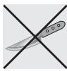
Pursuant to Directives 2002/95/EC, 2002/96/EC, 2003/108/EC, relating to the reduction of the use of hazardous substances in electrical and electronic appliances, as well as to the disposal of refuse, the crossed out bin symbol on the appliance indicates that the product, at the end of its useful life, must be collected separately from other refuse. Therefore, the user must consign the product that has reached the end of its working life to the appropriate selective collection centres for electrical and electronic refuse, or deliver it back to the retailer when purchasing an equivalent product, on a one for one basis. Adequate selective collection for the subsequent forwarding of the decommissioned product to recycling, treatment and ecologically compatible disposal contributes to avoiding possible negative effects on the environment and on health and promotes the recycling of the materials of which the appliance consists. The illicit disposal of the product by the user results in the application of administrative sanctions.
The product does not contain substances in quantities sufficient to be considered hazardous to health and the environment, in accordance with current European directives.
3.2 Your environmental care
Our product's packaging is made of non-polluting materials, therefore compatible with the environment and recyclable. Please help by disposing of the packaging correctly. You can obtain the addresses of collection, recycling and disposal centres from your retailer or from the competent local organisations.

Do not discard the packaging or any part of it, or leave it unattended. It can constitute a suffocation hazard for children, especially the plastic bags.
Your old appliance also needs to be disposed of correctly.
Important: hand over your appliance to the local agency authorised for the collection of household appliances no longer in use. Correct disposal enables intelligent recovery of valuable materials.
Before disposing of your appliance it is important to remove doors and leave shelves in the same position as for use, to ensure that children cannot accidentally become trapped inside during play. It is also necessary to cut the connecting cable to the power supply, removing it along with the plug.
4. USING THE HOB
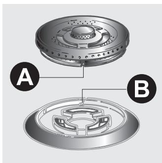
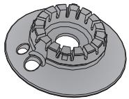
Before turning on the burners, make sure that the burners, flame-spreader crowns and racks are fitted correctly.
In the ultra-rapid burner, notch A must be aligned with pin B.
4.1 Lighting the burners
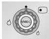
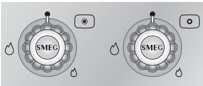
The burner controlled by each knob is shown next to the knob. The appliance is equipped with electronic ignition. Simply press the knob and simultaneously turn it anticlockwise to the minimum flame symbol, until it lights. On valved models, hold down the knob for about 2 seconds to keep the flame lit and to activate the safety device. The burner may go out when the knob is released. If this happens, repeat the procedure, holding the knob down for longer.
(On some models only)
Double-crown burners comprise an auxiliary and a rapid burner, controlled by two different knobs which permit to use both burners at the same time or to select one or the other as required.
If the burners should go out accidentally, after about 20 seconds a safety device will be tripped, cutting off the gas supply, even if the gas tap is open.
4.2 Practical tips for using the burners
For better burner performance and minimum gas consumption, pans with flat, even bases and with lids should be used, and their size should be in proportion to the burner (see "4.3 Pan diameters").
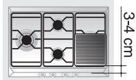
During cooking, in order to avoid burns or damage to the hob top and to the glass lid (when present), all pans or griddles must be positioned within the cooking hob perimeter and a minimum distance of 3-4 cm must be maintained from the knobs.

Make sure never to touch the lid glass with pots and pans that are still hot. The glass could crack and break with the heat.
4.3 Pan diameters

| (*) | Burner | min. and max. Ø (in cm) |
| 1 | Auxiliary | 7 - 18 |
| 2 | Semi-rapid | 10 - 24 |
| 3 | Medium Rapid | 12 - 24 |
| 4 | Large Rapid | 14 - 26 |
| 5 | Double crown ultra-rapid | 12 - 28 |
| 6 | Triple crown ultra-rapid | 22 - 28 |
| 7 | Fish burner | Suitable oval containers |
(*) For burner reference numbers, see "9.7 Arrangement of the burners on the cooking hob".
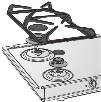
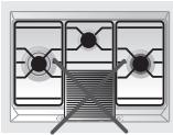
4.4 Using the griddle plate
A few precautions are necessary if you wish to use a griddle plate:
- leave a gap of at least 160 ~mm between the edge of the griddle plate and the side wall;
- if one of the burners close to the wooden rear wall is a triple crown burner, leave a gap of at least 160mm between this wall and the edge of the griddle plate;
- do not allow the burner flames to extend beyond the edge of the griddle plate;
- operate the burners underneath the griddle plate for 10 minutes at maximum power, then turn them down to the minimum setting. Never use the griddle plate for more than 45 minutes.
5. CLEANING AND MAINTENANCE

Important: DO NOT USE STEAM JETS FOR CLEANING THE HOB.

Before performing any operations requiring access to powered parts, disconnect the appliance from the power supply.
5.1 Cleaning the hob

To keep the hob in good condition it should be cleaned regularly after use. Let it cool first.
5.1.1 Ordinary daily cleaning
To clean and preserve surfaces, always use only specific products that do not contain abrasives or chlorine-based acids.
How to use: pour the product onto a damp cloth and wipe the surface, rinse thoroughly and dry with a soft cloth or a microfibre cloth.
5.1.2 Food stains or residues
Do not use metallic sponges or sharp scrapers: they will damage the surface.
Use ordinary non-abrasive products, together with anti-scratch sponges and wooden or plastic utensils if necessary.
Rinse thoroughly and dry with a soft cloth or chamois leather.

5.2 Cleaning the components
5.2.1 Knobs
The knobs should be cleaned with lukewarm water and washing up liquid. For easier cleaning they can be removed by pulling them upwards. Dry thoroughly after cleaning.
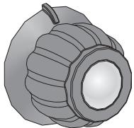

Do not use aggressive products containing alcohol or products for cleaning steel and glass when cleaning the knobs, as these products could cause permanent damage.
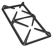
5.2.2 Racks
Remove the racks and clean them with lukewarm water and non-abrasive detergent, making sure to remove any encrustations. Replace them on the cooking hob.
These components must not be washed in the dishwasher.
5.2.3 Flame-spreader crowns
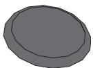
The flame-spreader crowns are removable. Wash them with hot water and non-abrasive detergent, making sure to remove any encrustations.
To remove burned on food residue, leave to soak in hot water and washing up liquid, then scrub using a scourer sponge.
For less stubborn residue and for polishing, use stainless steel cream cleaner Crema Inox with a microfiber cloth.
After cleaning ensure they are perfectly dry and reposition them correctly.
5.2.4 Igniters and thermocouples
For correct operation the igniters and thermocouples must always be perfectly clean. Check them frequently and clean them with a damp cloth if necessary. Remove any dry residues with a wooden toothpick or a needle.
5.2.5 Lid (on some models only)

Clean the glass or steel lid, where mounted, with lukewarm water. Never use abrasive sponges or detergents. To clean the rear part of the cooktop, remove the lid unit by lifting it upwards.
When finished cleaning, refit the cover making sure to insert it correctly.
Before lifting up the lid, dry out any liquid that may have dripped.
Never lower the lid when burners are on or still hot.
After cleaning, dry the appliance thoroughly to prevent water or detergent drips from interfering with its operation or creating unsightly marks.
6. POSITIONING IN THE COUNTER TOP

The following operation requires building and/or carpentry work so must be carried out by a competent tradesman.
Installation can be carried out on various materials such as masonry, metal, solid wood or plastic laminated wood as long as they are heat resistant (T 90^ ).
6.1 Fixing to the supporting structure
Create an opening with the dimensions shown in the figure in the top surface of the counter, keeping a minimum distance of 50~mm from the rear edge.
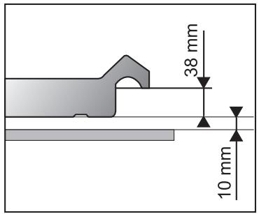
This appliance can be mounted against walls higher than the work surface on condition that a distance of 145 mm be kept between the appliance and the wall as shown in the figure so as to avoid damage from overheating.
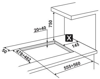
Make sure that there is a minimum distance of 750 mm between the stoves and any shelf that may be installed directly above it.
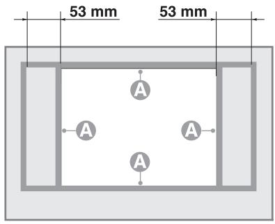
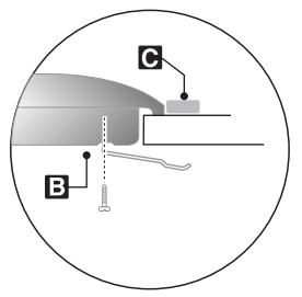
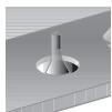
Carefully position the supplied insulating seal on the outer perimeter of the hole made in the counter top as shown in the figure below, trying to make it stick on the entire surface by applying light pressure on it with your hands. Refer to the dimensions in the figure, bearing in mind that the sides A must brush against the hole. Fix the hob to the unit using the appropriate brackets B supplied.
Carefully trim the surplus away from edge C beyond the seal. The dimensions given in the following drawing refer from the hole to the inside of the seal.
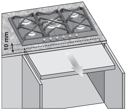
In case of installation on an empty kitchen unit with doors, a separation panel must be placed under the hob. Keep a minimum distance of 10mm between the bottom of the hob and the surface of the panel, which must be easily extractable to allow sufficient access for any technical assistance.
7. ELECTRICAL CONNECTION

Make sure that the voltage and capacity of the power line conform to the data shown on the plate located under the casing. Do not remove this plate for any reason.

The plug at the end of the supply cable and the wall socket must be of the same type and must conform to the applicable legislation on electrical installations. Make sure that the supply line is suitably earthed.

Pass the power supply cable through the back of the unit, taking care that it does not touch the bottom casing of the hob or the oven (if any) installed underneath it.

Fit the power supply line with a multipolar cut-out device with a contact opening gap equal to or greater than 3mm in an easily accessible position close to the appliance.

Avoid use of adapters and shunts.

If the power cable is replaced, the cross-section of wires in the new cable must be no less than 0.75 ~mm^2 (3 x 0.75 cable), remembering that the end for connection to the appliance must have an earth wire (yellow/green) which is at least 20 ~mm longer.

Only use a H05V2V2-F or similar cable resistant to the maximum temperature of 90^ . The cable must be replaced by a specialised technician who must carry out the connection to the power grid following the diagram below.
$$ \begin{array}{l} L = b r o w n \ N = \text {b l u e} \ \underline {{\underline {{\mathbf {z}}}}} = \text {y e l l o w / g r e e n} \ \end{array} $$

The power supply cable must be replaced by an authorised service centre to prevent any risks.

The manufacturer declines all responsibility for damage to persons or things caused by non-observation of the above prescriptions or by interference with any part of the appliance.
8. GAS CONNECTION
If the appliance is installed on an oven, you must avoid running the gas tube round the back of the oven in order to avoid overheating.
Connection to the gas supply network can be made using a rigid copper hose or a flexible steel hose with a continuous wall and in compliance with the guidelines established by the applicable standard.
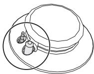
To facilitate the connection, connector A on the back of the appliance can be orientated laterally; loosen hexagonal nut B, twist connector A into the desired position then retighten hexagonal nut B (it is sealed with a rubber gasket). Once the operation is complete, check the hose fittings for leaks using a soapy solution; never use a flame.
The cooker hob is preset for natural gas G20 (2H) at a pressure of 20 mbar. For supplying it with other types of gas, see chapter "9. ADAPTATION TO DIFFERENT TYPES OF GAS". The gas inlet connection is threaded 12 " for external gas (ISO 228-1).
Connection with a rigid copper hose: The connection to the gas supply network must be made in such a way that it does not cause stresses of any type on the appliance.
The connection can be made using the adapter unit D with double cone, always inserting gasket C (provided) in between.
Connection with a flexible steel hose: use only continuous wall stainless steel hoses that comply with the applicable standards, making sure to always insert gasket C (provided) between connector A and flexible hose E.
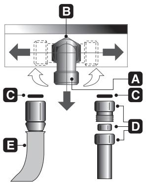
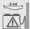
Installation with flexible hose must be carried out so that the length of the piping does not exceed 2 metres when fully extended; make sure that the hoses do not come into contact with moving parts and that they are not crushed in any way.
8.1 Connection to LPG

Use a pressure regulator and make the connection on the gas cylinder following the guidelines set out in the regulations in force.
Make sure that the supply pressure complies with the values indicated in the paragraph "3.2 Burner and nozzle characteristics tables".
8.2 Room ventilation

The room containing the appliance should have an air supply in accordance with the standards in force. The room where the appliance is installed must have enough air flow needed for the regular combustion of gas and the necessary air change in the room itself. The air vents, protected by grills, must be the right size to comply with current regulations and positioned so that no part of them is obstructed, not even partially.
The room must be kept adequately ventilated in order to eliminate the heat and humidity produced by cooking: in particular, after prolonged use, you are recommended to open a window or to increase the speed of any fans.
8.3 Extraction of the combustion products

The combustion products may be extracted by means of hoods connected to a natural draught chimney whose efficiency is certain or via forced extraction. An efficient extraction system requires precision planning by a specialist qualified in this area and must comply with the positions and distances indicated by the regulations. When the job is complete, the installer must issue a certificate of conformity.
9. ADAPTATION TO DIFFERENT TYPES OF GAS

Before carrying out the following operations, disconnect the appliance from the power supply.
The cooker hob is preset for natural gas G20 (2H) at a pressure of 20 mbar. If other types of gas are to be used, the nozzles must be replaced and the primary air must be adjusted.
In order to replace the nozzles and adjust the burners, the hob top must be removed as described below.
9.1 Removing the hob top
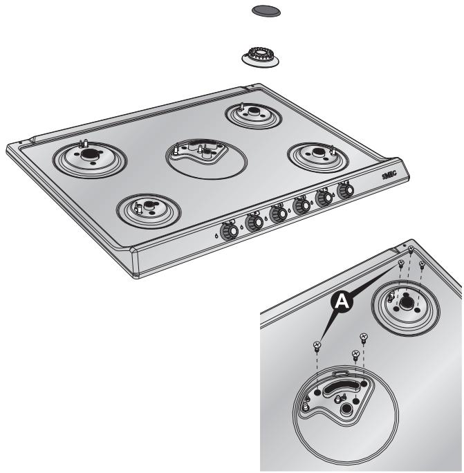
1 Remove all the knobs, pan stands, the caps and the flame-spreader crowns;
2 remove the screws and the nuts A that secure the burner supports;
3 lift the hob top from its housing;
4 replace the burner nozzles in accordance with the reference gas chart;
5 adjust the primary air as described in "9.5 Primary air adjustment".
9.2 Adjustment for LPG
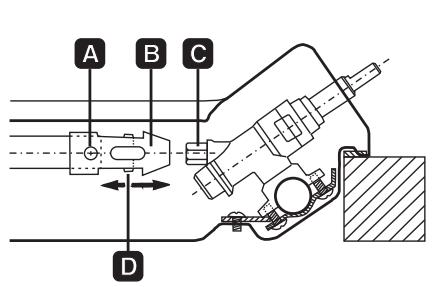
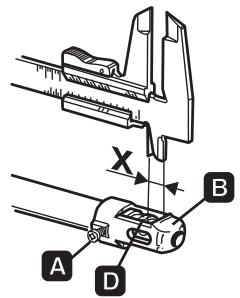
Loosen screw A and push support B all the way. Using a double head, remove nozzle C and replace it with the appropriate nozzle, following the instructions in the tables for the type of gas to be used. The nozzle tightening torque must be no more than 3 Nm. Reposition support B so that nozzle C is covered perfectly. Move the Venturi tube D to adjust the air flow until distance "X" is reached indicated in the chart in paragraph "5.5 Primary air adjustment" and then secure the tube by means of screw A. After the adjustments have been carried out, restore the seals with sealing wax or equivalent material.
| Burner | Rated heating capacity (kW) | LPG - G30/G31 28/37 mbar | ||||||
| Nozzle diameter 1/100 mm | By-pass mm 1/100 | Reduced capacity (W) | Capacity g/h G30 | Capacity g/h G31 | ||||
| Auxiliary (1) | 1.05 | 48 | 30 | 33 (*) | 380 | 76 | 75 | |
| Semi-rapid (2) | 1.65 | 62 | 30 | 33 (*) | 380 | 120 | 118 | |
| Medium rapid (3) | 2.55 | 76 | 37 | 40 (*) | 650 | 185 | 182 | |
| Large Rapid (4) | 3.1 | 85 | 43 | 750 | 225 | 222 | ||
| Ultra-rapid (5) | 3.3 | 87 | 55 | 65 (*) | 1200 | 240 | 236 | |
| Double crown | Internal (6) | 1.15 | 48 | 30 | 33 (*) | 380 | 84 | 82 |
| External (6) | 3.8 | 92 | 55 | 65 (*) | 1200 | 276 | 271 | |
| Fish burner (7) | 2 | 67 | 43 | 45 (*) | 750 | 145 | 143 | |
(*) By-pass value for appliances without valves.
9.3 Adjustment for city gas
Carry out the same steps as described in "9.2 Adjustment for LPG", but select the nozzles and adjust the primary air for city gas as indicated in the table below and in "9.5 Primary air adjustment".
Warning: Only units with safety valves can be used with city gas G110.
| Burner | Rated heating capacity (kW) | City gas - G110 8 mbar | ||
| Nozzle diameter 1/100 mm | Reduced capacity (W) | |||
| Auxiliary (1) | 1.05 | 132 | 380 | |
| Semi-rapid (2) | 1.65 | 165 | 380 | |
| Medium rapid (3) | 2.55 | 210 | 650 | |
| Large Rapid (4) | 3.1 | 240 | 750 | |
| Ultra-rapid (5) | 3.3 | 250 | 1200 | |
| Double crown | Internal (6) | 1.05 | 132 | 380 |
| External (6) | 3.9 | 290 | 1200 | |
| Fish burner | 2 | 190 | 750 | |
The values for city gas refer to appliances in category III 1a2H3+.
9.4 Adjustment for natural gas
The hob is preset for natural gas G20 (2H) at a pressure of 20 mbar. To reset the appliance for operation with this type of gas, carry out the same steps as described in "9.2 Adjustment for LPG", but select the nozzles and adjust the primary air for natural gas as indicated in the table below and in "9.5 Primary air adjustment". After the adjustments have been carried out, restore the seals with sealing wax or equivalent material.
| Burner | Rated heating capacity (kW) | Natural gas - G20 20 mbar | ||
| Nozzle diameter 1/100 mm | Reduced capacity (W) | |||
| Auxiliary (1) | 1.05 | 73 | 380 | |
| Semi-rapid (2) | 1.65 | 92 | 380 | |
| Medium rapid (3) | 2.55 | 115 | 650 | |
| Large Rapid (4) | 3.1 | 126 | 750 | |
| Ultra-rapid (5) | 3.3 | 130 | 1200 | |
| Double crown | Internal (6) | 1.05 | 73 | 380 |
| External (6) | 3.9 | 140 | 1200 | |
| Fish burner | 2 | 100 | 750 | |
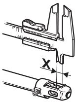
9.5 Primary air adjustment
Refers to distance "X" in mm.
| BURNER | G30/G3128/37 mbar | G2020 mbar | G1108 mbar | |
| Auxiliary (1) | 1.0 | 1.5 | 0.5 | |
| Semi-rapid (2) | 1.5 | 1.5 | 0.5 | |
| Medium rapid (3) | 1.5 | 1.0 | 1.0 | |
| Large Rapid (4) | 10.0 | 2.5 | 1.5 | |
| Ultra-rapid (5) | 2.5 | 2.0 | 1.5 | |
| Double crown | Internal (6) | 6.0 | 3.0 | 1.0 |
| External (6) | 10.0 | 3.0 | 5.0 | |
| Fish burner | 2.5 | 2.0 | 1.0 | |
To identify the burners on your hob, refer to the drawings in "9.7 Arrangement of the burners on the cooking hob".
9.6 Final operations
After making the adjustments described above, reassemble the appliance by following the instructions in "9.1 Removing the hob top" in reverse order.
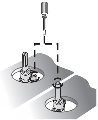
9.6.1 Adjusting the minimum for city and natural gas
Reposition the components on the burner and slide the knobs onto the tap rods.
Light the burner and set it on the minimum position. Extract the knob again and turn the adjustment screw inside or next to the tap rod (depending on the model) until the correct minimum flame is achieved.
Refit the knob and verify that the burner flame is stable (when turning the knob rapidly from the maximum to the minimum position the flame must not go out).
9.6.2 Adjusting the minimum setting for LPG
To adjust the minimum setting with LPG, you must tighten the screw inside or next to the tap rod (depending on the model) fully in a clockwise direction.
The bypass diameters for each individual burner are shown in table "9.2 Adjustment for LPG".

After adjustment with a gas other than the preset one, replace the label on the casing of the appliance with the label corresponding to the new gas. The label is inserted inside the pack together with the nozzles.
9.7 Arrangement of the burners on the cooking hob
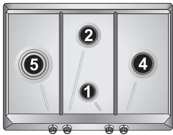
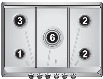
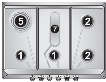
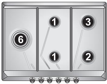
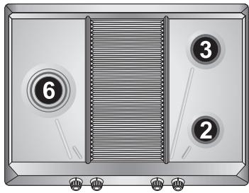
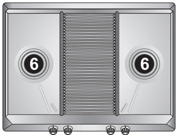
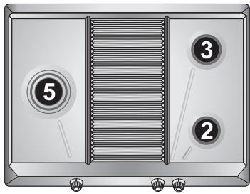
BURNERS
- Auxiliary
- Semi-rapid
- Medium Rapid
- Large Rapid
- Triple crown ultra-rapid
- Double crown ultra-rapid
- Fish burner
9.8 Lubrication of gas taps
Over time the gas taps may become difficult to turn and get blocked. Clean them internally and replace the lubrication grease.
This procedure must be carried out by a specialised technician.
- Contents
- INSTRUCTIONS FOR USE
- SAFETY PRECAUTIONS
- ENVIRONMENTAL RESPONSIBILITY
- Our environmental care
- Your environmental care
- USING THE HOB
- Lighting the burners
- Practical tips for using the burners
- Pan diameters
- Using the griddle plate
- CLEANING AND MAINTENANCE
- Cleaning the hob
- Ordinary daily cleaning
- Food stains or residues
- Cleaning the components
- Knobs
- Racks
- Flame-spreader crowns
- Igniters and thermocouples
- Lid (on some models only)
- POSITIONING IN THE COUNTER TOP
- Fixing to the supporting structure
- ELECTRICAL CONNECTION
- GAS CONNECTION
- Connection to LPG
- Room ventilation
- Extraction of the combustion products
- ADAPTATION TO DIFFERENT TYPES OF GAS
- Removing the hob top
- Adjustment for LPG
- Adjustment for city gas
- Adjustment for natural gas
- Primary air adjustment
- Final operations
- Adjusting the minimum for city and natural gas
- Adjusting the minimum setting for LPG
- Arrangement of the burners on the cooking hob
- BURNERS
- Lubrication of gas taps
Marque : SMEG
Modèle : SPR876RAGH
Catégorie : Four encastrable