TX-1000 - Autoradio Toxic - Notice d'utilisation et mode d'emploi gratuit
Retrouvez gratuitement la notice de l'appareil TX-1000 Toxic au format PDF.


| Type de produit | Autoradio |
| Marque | Toxic |
| Modèle | TX-1000 |
| Dimensions | 1 DIN (178 x 50 x 160 mm) |
| Poids | 0.8 kg |
| Alimentation | 12 V CC (batterie véhicule) |
| Puissance de sortie | 4 x 50 W (max) |
| Récepteur radio | FM/AM avec RDS |
| Lecteur audio | USB, auxiliaire 3.5 mm |
| Connectivité | Bluetooth pour appel mains-libres et streaming |
| Affichage | Écran LCD rétroéclairé |
| Fonctions principales | Radio, Bluetooth, USB, AUX, égaliseur, télécommande incluse |
| Entretien et nettoyage | Nettoyer avec un chiffon doux et sec. Éviter les solvants. |
| Sécurité | Face avant amovible (détachable) pour prévention du vol |
| Pièces détachées et réparabilité | Face avant, câblage, antenne disponibles chez revendeur agréé |
| Informations générales | Notice d'utilisation disponible en PDF sur notice-facile.com |
FOIRE AUX QUESTIONS - TX-1000 Toxic
Questions des utilisateurs sur TX-1000 Toxic
0 question sur cet appareil. Repondez a celles que vous connaissez ou posez la votre.
Poser une nouvelle question sur cet appareil
Téléchargez la notice de votre Autoradio au format PDF gratuitement ! Retrouvez votre notice TX-1000 - Toxic et reprennez votre appareil électronique en main. Sur cette page sont publiés tous les documents nécessaires à l'utilisation de votre appareil TX-1000 de la marque Toxic.
MODE D'EMPLOI TX-1000 Toxic
Toxic®
Toxic®
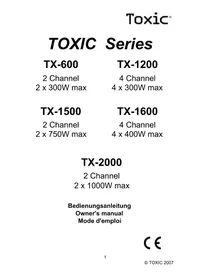
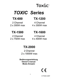
Toxic Series
| Technische Daten Specifications | TX-500 | TX-1000 |
| Max Power | 500W | 1000W |
| Max. Watt pro Kanal Max Power per channel | 2 X 250W | 4 X 250W |
| SN/Ratio | 95dB | 95dB |
| Frequenzgang Frequency Response | 10Hz - 40KHz | 10Hz - 40KHz |
| THD | 0.05% | 0.05% |
| Kanal Trennung Channel Separation | 55dB | 55dB |
| Hoch- und Tiefpass High- and Lowpass | 40Hz - 250Hz | 40Hz - 250Hz |
| Dämpfungsfaktor Damping Factor | 180 | 180 |
| Abmessungen Dimensions (LxHxD mm) | 181 X 58 X 260 | 281 X 58 X 260 |
TX-500
2 channel
500 W max
TX-1000
4 channel
1000 W max
Bedienungsanleitung
Owner's manual
Mode d'emploi
Manual de Instrucciones
Istruzione d'uso
92
Toxic®
INTRODUCTION
Congratulations on the purchase of this Toxic Amplifier. Rest assured you have purchased a quality product designed and engineered to give you many years of uncompromised musical service. This amplifier has been designed using the latest in electronic technology available today and will provide you with years and years of high quality sound level amplification and reproduction.
This amplifier has been designed with a fully regulated 100% MOS-FET Power supply assuring extremely quick switching response and self protection with soft starting power turn on.
PROTECTION CIRCUITRY
Advanced protection circuits have been designed into all our amplifiers. The protection circuits will disable the amplifiers if it senses an input overload, speaker short circuit or extreme high temperature conditions. When the protection circuit is in operation the amplifier will go into a self preservation mode. At this time please check your system to see what is causing the protection circuit to fire. The amplifier can be reset by turning the remote power off and then on again. If the system shuts down because of the thermal overload condition, allow the amplifier to cool down before restarting. If the amplifier shuts down because of an input overload or speaker short circuit please be sure to correct these conditions before restarting the amplifier.
WE WANT YOU LISTENING FOR A LIFETIME
Used wisely, your new sound equipment will provide a lifetime of fun and enjoyment. Since hearing damage from loud noise is often undetectable until it is too late, we recommend you to avoid prolonged exposure to excessive noise.
Toxic®
TX-500
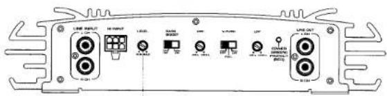
Sensitivity Control
• Two Channel Bridgeable Amplifier.
• Heavy Duty Aluminium Alloy Heatsink Chassis.
• Built In Electronic Crossover for High- and Lowpass, adjustable from 40 Hz to 250 Hz
- RCA-Output
• Bass Boost at 45Hz, switchable
• Continuously Variable Input Gain Adjustment
• Gold Plated RCA Input with floating ground
• Remote Turn-on / Turn-off Circuit.
• MOS-FET Pulse Width Modulated Power Supply.
- Soft Turn-on Circuit.
• Thermal Overheat Protection.
• Speaker Short Circuit Protection.
• Automotive Style Protection Fuses.
• Goldplated Speaker- and Power Terminals
• Power on LED Indicator.
• 2 Ohm Stable Operation with Output Power Increase
• Tri-Mode capable (Phantom Center or Subwoofer)
Toxic®
TX-1000

• Four Channel Bridgeable Amplifier.
• Heavy Duty Aluminium Alloy Heatsink Chassis.
• Built In Electronic Crossover for High- and Lowpass, adjustable from 40 Hz to 250 Hz
- RCA-Output
- Mode-Switch
• Bass Boost at 45Hz, switchable
• Continuously Variable Input Gain Adjustment
• Gold Plated RCA Input with floating ground
• Remote Turn-on / Turn-off Circuit.
• MOS-FET Pulse Width Modulated Power Supply.
- Soft Turn-on Circuit.
• Thermal Overheat Protection.
• Speaker Short Circuit Protection.
• Automotive Style Protection Fuses.
• Upright Easy Access Speaker- and Power Terminals
• Power on LED Indicator.
• 2 Ohm Stable Operation with Output Power Increase
• Tri-Mode capable (Phantom Center or Subwoofer)
Toxic®
BUILT-IN ELECTRONIC CROSSOVER
The Toxic-Series are equipped with built in switchable electronic x-overs. The filters will operate on both channels and also in bridged mode. When using the amplifier in bridged mode only 4 ohm speaker load should be used. The electronic network is switchable as Lowpassfilter "LPF or as Highpassfilter "HPF". In both modes the crossover frequency is continuously adjustable from 40Hz to 250KHz. This function is available for all channels and the Line out.
A switchable bass boost at 45Hz is included in all models.
2-OHM OPERATION
This unit was designed to operate efficiently at loads down to 2 Ohms. What this means is that you can do an installation of four-8 Ohm speakers per channel using parallel wiring or two-4 Ohm speakers per channel in parallel.
When operating at 2 Ohms, the amplifier increases its power output by approximately 50 percent. The current draw of the amplifier will also increase by about the same amount. Be sure that you have enough current to run the amplifier into a 2 Ohm load otherwise distorted music will be reproduced.
Note:
Do not use a 2 Ohm load in the bridged mode.
The amplifier accepts 4-8 Ohms only in the bridged mode.
MECHANICAL INSTALLATION
Mark the locations for the mounting screw holes by holding the AMPLIFIER in place and using a scribe or one of the mounting screws, inserted in each mounting hole in turn. To mark the mounting surface if carpeted, measure the hole centres and mark with a felt-tip pen. Drill pilot holes for the mounting screws into the holes of the system, insert the mounting screws into the holes and tighten them securely.
23
Toxic®
Toxic
CAUTION
Investigate the layout of your automobile throughly before drilling or cutting any holes. Take care when you work near the gas tanks, lines, or hydraulic lines, and electrical wiring. Don't use the power amplifier unmounted. Attach this system securely to the automobile to prevent damage, particularly in the event of an accident. Don't mount this system so that the wire connections are unprotected or are subject to pinching or damage from nearby objects. The +12VDC power wire must be fused at the battery positive terminal connection. Before making or breaking power connections at the system power terminals, disconnect the +12V wire at the battery end. Confirm your radio / cassette player and / or other equipment is turned off while connecting the input jacks and speaker terminals. If you need to replace the power fuse, replace it only with a fuse of different type or rating may result in damage to this system which isn't covered by the warranty.
HIGH LEVEL EINGANG = HOCHPEGELEINGÄNGE
In case your car stereo is not equipped with a pre-amplifier output you should connect the car stereo speaker outputs through the white connector. Please take care for correct polarity connection. Wrong cionnection can destroy the output stage of your car-stereo.
TX-500

1 = White, Channel 1+
2 = Black, GND
3 = White/Black, Channel 1-
4 = Grey, Channel 2+
5 = Grey/Black, Channel 2-
TX-1000

1 = White, Channel 1 +
2 = White/Black, Channel 1 -
3 = Black, GND
4 = Green/Black, Channel 3 -
5 = Green, Channel 3 +
6 = Grey, Channel 2
7 = Grey/Black, Channel 2 -
8 = Violet/Black, Channel 4 -
9 = Violet, Channel 4 +
ELECTRICAL INSTALLATION
These amplifiers are equipped with easy top access screw terminals. These terminals are 14 carat Gold Plated to insure excellent electrical contact and to resist corrosion.
See DIAGRAMS for electrical installation of all amplifiers. We suggest using at least 8 gauge wire for the power and ground connections. Wire the amplifier directly to the car battery. For the ground connection use the shortest possible route to a good chassis ground point.
Wire the remote connection to the auto start lead of your equalizer or power antenna.
Power fuses protects both this amplifier and the automobile electrical system from wrong conditions. The fuse is standard automotive type. Replace only with the same current rating fuse otherwise damage or fire can result.
For RCA line level input, simply plug your source units RCA output in to the RCA input of the amplifier. See DIAGRAMS. Set the gain control into the 12 o'clock position. Turn on your radio and set volume to the 1/2 way mark. Adjust the gain control of the amplifier to a comfortable listening level.
NOTE
The gain control of any car audio amplifier should not be mistaken for a volume control. It is a sophisticated device designed to match the output level of your source unit to the input level of the amplifier. Do not adjust the level to maximum unless your input level requires it. Not following this instruction will result in an input overload to the amplifier and high levels of distorted levels of distorted levels of musical reproduction
Toxic®
GND (-) = GROUND CONNECTION
Connect the Gnd terminal to the chassis ground of your car and take care of best electric and mechanic contact. In doing so, drill a hole into the car chassis near the amplifier, then remove colour, dirt or any other substance from the ground point. After that, fasten the cable end with added ring terminal by using a screw. Ensure that the ground connection is as short as possible and that the cable diameter is sufficient (min. 6mm ^2 ). Route the ground cables from the radio and all other equipment parts, like equalizer, active crossover network or other amplifiers, to the same ground point.
BATT (+) = POWER SUPPLY
Connect the Batt terminal to the positive pole of the battery with a lead cable and add a fuse into the power cable in a distance of not more than 30 cm from the battery. The lead cable's diameter should be at least 6mm² for a length of 3m and 8mm² for a lenght of 6m.
REM (ON / OFF) = REMOTE CONTROL
Connect the Rem terminal to the automatic antenna connector of your car radio. Now when turning on and off your car radio, the amplifier automatically switches on and off. A cable diameter of 0.5mm^2 is sufficient.
ON = LED POWER INDICATOR
After the orderly connection of the three power terminals, the LED indicator shines green and goes out with "off".
PROTECT = LED PROTECTION INDICATOR
This set is equipped with an overload protection. Immediately upon overloading (due to short circuit or much increased temperature) the overload protection is activated, and the red LED indicator is shining. Through this, the amplifier is protected against damage. In case of thermal protection a certain short cooling time must be allowed after which the amplifier automatically resumes operation.
Toxic
FUSE
The amplifier is equipped with a plug-in auto fuse protecting set against fault conditions. Do not use a fuse with a higher value and never bridge the fuse over, as this may lead to non-reparable damage so that any claim for warranty is denied.
GAIN = INPUT LEVEL CONTROL
The input level control allows the system to work well within a wide range of output levels. Choose the adjustment in the way that you achieve a sound most possibly without any distortion. As a guideline the following procedure is recommended:
If you use several amplifiers, the adjustment has to be made for each set separately. Tune in the volume of your car radio to 2/3 of the maximum volume. Now turn the gain control of the amplifier from „min“ to „max“ direction until you can hear distortions. Then turn the level control a little back to „min“. The gain control adjustment is finished now.
When using a 4-channel amplifier, make this adjustment separately for channel 1/2 and channel 3/4.
Attention: If you use 2 ohm speakers in stereo mode, tri-mode or 4 ohm speakers in bridge mode and the overload protection is triggered out, turn the gain control to „min“ direction, until the operation is free of trouble.
BASS-BOOST
The switchable Bass-Boost function increases the sound at 45Hz/12dB.
LINE-OUT
Das Eingangssignal von Kanal1/2 steht an den Line-Out Ausgängen zur Verfügung um eine weitere Endstufe anzusteuern.
Toxic®
Toxic
TX-500
CONNECTION AND OPERATION

TX-1000
CONNECTION AND OPERATION

CONNECTIONS AND CONTROLS
1) Speakerconnection L-
2) Speakerconnection L+
3) Speakerconnection R-
4) Speakerconnection R+
5) Ground Connection
6) Remote Connection
7) +12V Connection
8) Fuse
9) RCA Input
10) Line Out
11) Level Control Adjustment
12) Adjustable Crossoverfrequency
13) Bass-Boost, switchable
14) On/Protecion-LED
CONNECTIONS AND CONTROLS
1) Fuse
2) +12V Connection
3) Remote Connection
4) Ground Connection
5) Speakerconnection CH1 -
6) Speakerconnection CH1 +
7) Speakerconnection CH2-
8) Speakerconnection CH2 +
9) Speakerconnection CH3 -
10) Speakerconnection CH3 +
11) Speakerconnection CH4 -
12) Speakerconnection CH4 +
13) RCA-Input CH1/CH2
14) RCA-Input CH3/CH4
15) Line Out
16) Level/Frequency Adjust CH1/CH2
17) Bass-Boost, switchable
18) Level/Frequency Adjust CH3/CH4
19) Crossovernetwork CH1/CH2
20) Mode switch
21) Crossovernetwork for CH3/CH4
Toxic®
Speakerconnection Model TX-500
a) Stereo-Mode
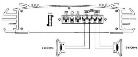
b) Mono-Mode

30
© Toxic 2004
Toxic
c) Phantom-Channel-Mode (TRI-Mode) with Center

d) Phantom-Channel-Mode (TRI-Mode) with Subwoofer

31
© Toxic 2004
Toxic\*
Toxic
Speakerconnection Model TX-1000
a) 4-Channel -Mode
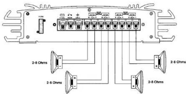
b) 2-Channel-Mode
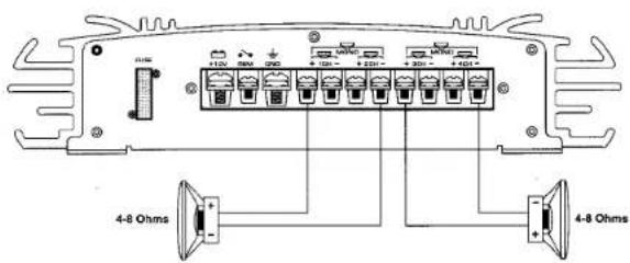
32
c) 3-Channel-Mode

d) 5-Channel-Mode with Subwoofer

33
Toxic®
Toxic
HOW TO PROCEED IN CASE OF FAULTS
No function
The connection cable is not connected correctly (= terminals Batt/Gnd/Rem). Ensure that all connections have electric and mechanic contact and that the jacket has been removed. The fuse is defective - pay attention to the correct value of a new fuse!
No sound
Speaker cables or speaker plugs are not connected correctly.
No sound / green LED shines
The plus and minus wires of the speaker cables have contact, thus eliminate the short circuit.
If you use a 2 ohm speaker in stereo mode, a 4 ohm speaker in bridge mode or tri-mode and the set is overloaded, then turn the gain control to „min“ until the operation is free of trouble.
One channel without function
The balance control is not in centre position, thus correct the position. The speaker or its lead is defective, so check the speaker, lead and connections.
Poor sound quality (distortions)
The speakers are overloaded, therefore turn down the volume level and check the volume control positions.
No stereo sound and a weak bass
Speaker cables (+) and (-) are mixed up, unit wired out of phase.
INTERFERENCE
All cables are source of interference or gather them. The power cable and Cinch/RCA audio cable are very prone to interference; the remote cables are less prone. There is often interference caused by the generator (piping), ignition (crackling) or other car electronic parts. Most of these problems can be eliminated by correct and careful cabling. In doing so, there are the following guidelines:
- Use only a shielded audio cables for the wiring between „low level in“ of the amplifier and RCA or DIN outputs of the radio.
- Lay the signal, speaker and power cables separately with enough distance from another and also from any other car cable. If not possible, you can lay the circuit and ground cable together with the serial cables. Audio and speaker cable should be as far away from these as possible. The Rem cable to the automatic antenna output of the radio can be laid together with the signal cables.
- Avoid ground loops by laying the ground wiring of all components to a centre point in a star-like way. You can find the best central point in measuring the voltage directly at the battery. Now compare this voltage value with the chosen ground point and the (+) terminal of the amplifier. If the measured voltage is only less different, you have found the correct central. Otherwise you have to look for another point. You should measure with the ignition being switched on and additionally switched on consumers (rear window heating, light etc).
- If there are pickups from external electrical sources into the speaker cables, divide the core leads and twist them together.
- If there are noises from the car electrics, add an interference suppression choke into the power wiring.
- If there are humming noises, use thicker ground cables or add further ground cables to the chassis.
- To reduce contact resistance and bad and loose contacts, please tin the cable ends or use multicore cable ends, spade terminals or others. Gold-plated spade terminals are free of corrosion and have the lowest contact resistance.
- Should all these measures be without any success, the use of a ground loop isolator may solve the problem.
CAR POWER PACK
CPP-1000
TW-300RD
12" Subwooferbox
300 WATT
TW-6933RD 3-Wege Koaxial-Lautsprecher 300 WATT
Stabiler Metallkorb
3-Wege System
▶ Ferrit Hoch- und Mitteltöner
▶ PP-Membrane mit Gummisicke
Inkl. Grill und Einbaumaterial
Technische Daten:
Max. Leistung 300 W
Frequenzbereich 40 Hz - 21 KHz
SPL 89 dB
Impedanz....4 Ohm
Bass 155x255 mm
Einbautiefe 85 mm
▶ 12" Basslautsprecher
▶ Beschichteter Bass
▶ Geschlossenes Gehäuse
Klemmterminal
▶ 18 mm Holzgehäuse
▶ Grauer Schutzfilzbezug
Technische Daten:
Max. Leistung...... 300 W
Frequenzbereich 50 Hz - 25 KHz
SPL 92 dB
Impedanz......4 Ohm
Maße 41x36x25x36 cm
TX-1000
4-Kanal-Verstärker 1000 WATT
▶ MOS-FET PWM Schaltnetzteil
mit Softstart
▶ regelbarer tiefpass 40Hz-250 Hz
▶ regelbarer Hochpass 40Hz-250 Hz
▶ Lautsprecher-Eingänge
NF-Ausgang
Technische Daten:
Max. Leistung...... 4 x 250 W
Max. gebrückt 2 x 500 W
S/N Ratio 88 dB
Dämpfungsfaktor ..... 180
Frequenzgang.... 10 Hz - 40 KHz
Abmessungen.... 280 x 57 x 260


CE

Art.-Nr.: 379195
e4 020766
- Toxic®
- Toxic Series
- INTRODUCTION
- PROTECTION CIRCUITRY
- WE WANT YOU LISTENING FOR A LIFETIME
- TX-500
- BUILT-IN ELECTRONIC CROSSOVER
- 2-OHM OPERATION
- Note:
- MECHANICAL INSTALLATION
- Toxic
- CAUTION
- HIGH LEVEL EINGANG = HOCHPEGELEINGÄNGE
- ELECTRICAL INSTALLATION
- NOTE
- GND (-) = GROUND CONNECTION
- BATT (+) = POWER SUPPLY
- REM (ON / OFF) = REMOTE CONTROL
- ON = LED POWER INDICATOR
- PROTECT = LED PROTECTION INDICATOR
- FUSE
- GAIN = INPUT LEVEL CONTROL
- BASS-BOOST
- LINE-OUT
- CONNECTIONS AND CONTROLS
- Speakerconnection Model TX-500
- Toxic\*
- Speakerconnection Model TX-1000
- HOW TO PROCEED IN CASE OF FAULTS
- No function
- No sound
- No sound / green LED shines
- One channel without function
- Poor sound quality (distortions)
- No stereo sound and a weak bass
- INTERFERENCE
- CAR POWER PACK
- CPP-1000
- TW-300RD
- 12" Subwooferbox
- WATT
- TW-6933RD 3-Wege Koaxial-Lautsprecher 300 WATT
- TX-1000
- 4-Kanal-Verstärker 1000 WATT
Marque : Toxic
Modèle : TX-1000
Catégorie : Autoradio