TX-400 - Autoradio Toxic - Notice d'utilisation et mode d'emploi gratuit
Retrouvez gratuitement la notice de l'appareil TX-400 Toxic au format PDF.


| Type de produit | Autoradio |
| Marque | Toxic |
| Modèle | TX-400 |
| Dimensions (L x H x P) | 178 x 50 x 100 mm |
| Poids | 0,5 kg |
| Alimentation | 12 V CC (véhicule) |
| Puissance de sortie maximale | 4 x 50 W |
| Gamme de fréquences radio | FM 87,5 – 108 MHz / AM 530 – 1710 kHz |
| Formats audio supportés | MP3, WMA, WAV |
| Connectivité | Entrée USB, entrée AUX, Bluetooth intégré |
| Affichage | Écran LCD rétroéclairé |
| Fonctions principales | Radio RDS, horloge, télécommande incluse, lecture aléatoire, répétition |
| Entretien et nettoyage | Essuyer avec un chiffon doux et sec. Éviter les solvants. |
| Sécurité | Face avant amovible pour prévenir le vol |
| Pièces détachées et réparabilité | Face avant, câblage, antenne disponibles séparément |
| Garantie | 2 ans |
| Température de fonctionnement | -20 °C à 60 °C |
| Informations générales | Conçu pour une installation en façade ISO/DIN |
FOIRE AUX QUESTIONS - TX-400 Toxic
Questions des utilisateurs sur TX-400 Toxic
0 question sur cet appareil. Repondez a celles que vous connaissez ou posez la votre.
Poser une nouvelle question sur cet appareil
Téléchargez la notice de votre Autoradio au format PDF gratuitement ! Retrouvez votre notice TX-400 - Toxic et reprennez votre appareil électronique en main. Sur cette page sont publiés tous les documents nécessaires à l'utilisation de votre appareil TX-400 de la marque Toxic.
MODE D'EMPLOI TX-400 Toxic
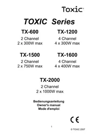
TOXIC Series
TX-400N
2 Channel 2 x 200W max
TX-600N
2 Channel 2 x 300W max
TX-800N
4 Channel 4 x 200W max
TX-1200N
4 Channel 4 x 300W max
TX-1500N
2 Channel 2 x 750W max
TX-1600N
4 Channel 4 x 400W max
Toxic®
EINFÜHRUNG
Bevor Sie diesen Hochleistungsverstärker anschließen, lesen Sie bitte sorgfältig die Bedienungsanleitung. Die Anweisungen bezüglich Anschluß und Einbau sind aufs genaueste zu beachten. Falls nötig, sollten Sie Ihren Fachhändler hinzuziehen.
Alle DC-Anschlüsse, Signal-Eingang und Lautsprecher-Ausgänge können durch vergoldete Schraubterminals bzw. Cinch-Buchsen leicht ausgeführt werden.
EINBAU-HINWEISE
Bitte wählen Sie einen Einbauplatz, der nicht direkt Weitereinflüssen ausgesetzt ist. Beachten Sie, daß das Gerät sich erhitzt, so daß ein gut belüfteter Ort am geeignetsten ist. Ziehen Sie auch das Wagen-Handbuch zu Rate. Ein Einbau ist unter den Sitzen oder im Kofferraum möglich. In jedem Fall jedoch sollte der Einbau sorgfältig vorgenommen werden, um die volle Leistung und Zuverlässigkeit des Verstärkers zu gewährleisten.
Halten Sie die Kabelverbindungen so kurz wie möglich (mit ausreichendem Durchmesser), um die Leistungsverluste so gering wie möglich zu halten und eine bessere Ausgangsleistung zu erzielen.
Zur Sicherheit sollten möglichst alle Kabel durch die vorhandenen Kabelschächte des Wagens geführt werden. Achten Sie beim Veriegen auf scharfe Ecken oder Kanten, um die Kabel nicht zu beschädigen.
Verlegen Sie alle Kabel soweit wie möglich entfernt vom Zündkabel, Modulen im Kofferraum sowie vom Armaturenbrett. Befestigen Sie eine Sicherung am (+) Stromkabel in einem Abstand von nicht mehr als 30 cm vom positiven Batteriepol.
Halten Sie die Länge der Stromkabel so kurz wie möglich. Es ist besser, kurze Stromkabel zu benutzen und ggf. längere Lautsprecherkabel. Um Störungen zu vermeiden beachten Sie bitte die Anweisungen.
Toxic®
EINBAU
Bei der Suche nach einem geeigneten Einbauplatz sollten Sie einen Ort wählen, der dem Verstärker ausreichende Belüftung garantiert. Bevor Sie den Verstärker einbauen, vergewissern Sie sich, daß alle benötigten Teile vorhanden sind (Schrauben etc). Halten Sie dann den Verstärker an den ausgewählten Platz und markieren Sie die Bohrlöcher. Bohren Sie dann die Löcher und schrauben Sie anschließend das Gerät fest.

Achtung:
Garantie kann nicht gewährt werden, wenn Fehler externer Natur auftreten, wenn das Garantiesiegel zerstört wurde oder wenn das Gerät falsch eingebaut wurde.
Toxic®
LOW LEVEL EINGANG = CINCH/RCA EINGÄNGE
Wenn Ihr Autoradio mit einem Vorverstärker Ausgang (Cinch/RCA oder DIN) ausgestattet ist, verbinden Sie die Cinch/RCA Eingangsterminals mit den Vorverstärker Ausgangsterminals des Radios. Achten Sie auf die korrekte Kanal Anordnung.
Falls Sie eine 4-Kanal Endstufe erworben haben und Ihr Autoradio nur mit einem 2-Kanal Vorverstärker Ausgang versehen ist, benutzen Sie einen Y-Adapter, um die Nutzung aller 4 Eingänge des Verstärkers zu ermöglichen. Die Markierung der roten Anschlußterminals bedeutet „rechts“.
LINE OUT
Das Eingangssignal von Kanal 1/2 steht an den Line-Out Ausgängen zur Verfügung um eine weitere Endstufe anzusteuern.
LAUTSPRECHER ANSCHLÜSSE
4-KANAL
Der Verstärker kann mit 2 bis 6 Lautsprechern arbeiten.
2-KANAL
Der Verstärker kann mit 1 bis 3 Lautsprechern arbeiten. Die Lautsprecherimpedanz ist variierbar von 2, 4 oder 8 Ohm, abhängig vom Modus. Achten Sie auf die korrekte Polarität, wenn Sie die Lautsprecher anschließen. Die Leistung der Lautsprecher sollte mit der Ausgangsleistung des Verstärkers korrelieren. Bitte beachten Sie dabei, daß sich die Ausgangsleistung des Verstärkers bei 2 Ohm Lautsprechern erhöht und bei 8 Ohm Lautsprechern verringert. Im Stereo-Modus sollten nur Lautsprecher-Kabel mit einem Minimum-Durchmesser von 1.5mm² genutzt werden. Im Brücken-Modus sollten es mindestens 2.5mm² sein. Die Lautsprecher sollten niemals einen Kurzschluß verursachen können oder mit der Masse verbunden werden.
Toxic®
STEREO-MODUS
Die normale Lautsprecher Impedanz beträgt 4 Ohm pro Kanal, 2 oder 8 Ohm sind ebenfalls möglich.
Die Anschlüsse sehen im 4 Kanal Stereo-Modus wie folgt aus:

Die Anschlüsse sehen im 2 Kanal Stereo-Modus wie folgt aus:

Toxic®
BRÜCKEN-MODUS 4-KANAL-VERSTÄRKER
Um die Ausgangsleistung zu erhöhen, kann der Verstärker im Brücken-Modus betrieben werden. Dabei weden die Kanäle 1 und 2 sowie 3 und 4 so zusammengeschlossen, daß nur 2 Kanäle zur Verfügung stehen.
Die Minimum Lautsprecher Impedanz liegt bei 4 Ohm. Beim Betrieb im Brücken-Modus ist es möglich, 2 Lautsprecher (2 oder 4 Ohm) in Serie zu schalten, 2 Lautsprecher (8 Ohm) parallel anzuschließen oder aber nur einen Lautsprecher (4 oder 8 Ohm) pro Kanal.
Ein gemischter Stereo-Betrieb zum Beispiel mit Kanal 1 + 2 und Brücken-Modus mit Kanal 3 + 4 sind ebenso möglich.
Brücken-Modus mit 2 Lautsprechern (4-8 Ohm):

Brücken-Modus mit 2 Lautsprechern (4 Ohm) in Serienschaltung und 2 Lautsprechern (8 Ohm) im Parallel-Anschluß:

Toxic
BRÜCKEN-MODUS 2-KANAL-VERSTÄRKER
Um die Ausgangsleistung zu erhöhen, kann der Verstärker im Brücken-Modus betrieben werden.
Die Minimum Lautsprecher Impedanz liegt bei 4 Ohm. Beim Betrieb im Brücken-Modus ist nur eine Mono-Wiedergabe möglich.
Brücken-Modus mit einem Lautsprecher:

Brücken-Modus mit 2 Lautsprechern (4 Ohm) in Serienschaltung:

Brücken-Modus mit 2 Lautsprechern (8 Ohm) in Parallelschaltung:

Toxic®
TRI-MODE
Wenn Sie einen Subwoofer oder Center-Lautsprecher im Stereo-Modus benutzen wollen, können Sie diese auch im Brücken-Modus mit den Lautsprecher Terminals verbinden. Dabei muß aber eine zusätzliche passive Frequenzweiche (12dB slope) angeschlossen werden, weil weder ein Subwoofer (optimaler Frequenzbereich bis zu 150 Hz) noch ein Center-Lautsprecher (200 Hz - 6 KHz) mit dem vollen Frequenzbereich arbeiten kann.
Bei der Tri-Mode Nutzung sollten nur 4 Ohm Lautsprecher für die linken und rechten Kanalseiten genutzt werden. 8 Ohm Impedanz sind bei einem dritten Lautsprecher empfohlen, 4 Ohm sind jedoch auch möglich.
Subwoofer in Tri-Mode Nutzung sollten ohne Gehäuse betrieben werden (Free-Air-Subwoofer). Um die besten Ergebnisse zu erzielen, können Sie versuchsweise die Polarität des Subwoofers ändern. Wenn so ein stärkerer Bass-Sound erzielt werden kann, sollte die Polarität geändert werden. Wenn Sie einen Subwoofer als dritten Lautsprecher verwenden, sollten die beiden anderen Lautsprecher von den tiefen Frequenzen des Subwoofers befreit werden. Dafür wird ein 8 dB Hoch-Pass-Filter empfohlen. Dadurch wird der Klang der anderen Lautsprecher oftmals transparenter und die Leistung der Lautsprecher erhöht sich.
Tri-Mode mit Subwoofer für 4-Kanal-Verstärker:

8
© Toxic 2005
Toxic®
Tri-Mode mit einem Center-Lautsprecher für 4-Kanal-Verstärker
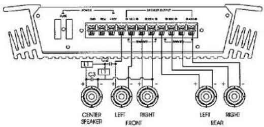
Tri-Mode mit Subwoofer für 2-Kanal-Verstärker:

9
© Toxic 2005
Toxic®
Tri-Mode mit einem Center-Lautsprecher für 2-Kanal-Verstärker:
GND (-) = MASSE ANSCHLUSS

Die folgenden Werte sollten für die Frequenzbestimmenden Bauteile verwendet werden:
C = Kondensator
L = Spule
C = 330uF Bipolarer (Tonfrequenz) Elko
L1 = 10 mH
C1 = 100uF für 4 Ohm Subwoofer
L1 = 15 mH
C1 = 100uF für 8 Ohm Subwoofer
L2 = 9 mH
C2 = 68uF für 8 Ohm Center-Lautsprecher
L3 = 0.3mH
C3 = 2,2 uF
Toxic®
Verbinden Sie den Gnd-Anschluss mit dem Chassis des Wagens und sorgen Sie für einen guten Kontakt. Bohren Sie dafür ein Loch in das Wagen-Chassis nahe beim Verstärker. Dann entfernen Sie an der Bohrstelle bitte Farbe und jeglichen Schmutz. Danach befestigen Sie das Kabel mit dem mit R ing-Anschluß und Schraube. Vergewissern Sie sich, daß der Masse-Anschluß so kurz wie möglich ist, und daß der Kabel-Durchmesser ausreichend ist (min. 6mm²).
BATT (+) = STROMANSCHLUSS
Verbinden Sie den Batterie-Anschluß mit dem positiven Pol der Batterie durch ein Kabel und setzen Sie eine Sicherung an das Stromkabel in einer Entfernung von nicht mehr als 30 cm von der Batterie. Der Durchmesser des Kabels sollte bei einer Länge von 3m mindestens 10mm² und bei einer Länge von 6m mindestens 16mm² betragen.
REM (ON/OFF) = AUTOMATISCHE EINSCHALTLEITUNG
Verbinden Sie den Rem-Terminal mit dem automatischen Antennen-Anschluß Ihres Autoradios. Wenn Sie nun das Autoradio ein- bzw. ausschalten, schaltet sich der Verstärker automatisch mit ein bzw. aus. Ein Kabel von 0.5mm² Durchmesser ist hierbei ausreichend.
ON = LED EINSCHALTANZEIGE
Nach dem korrekten Anschluß der 3 Strom-Terminals wird die LED grün aufleuchten und somit die Betriebsbereitschaft signalisieren
PROTECT = LED SCHUTZ-ANZEIGE
Dieses Gerät ist mit einem Überlast-Schutz ausgestattet. Sofort bei Überlastung (Kurzschluß, Hitze) wird der Überlast-Schutz aktiviert und die rote LED leuchtet auf. Dadurch wird der Verstärker gegen Schäden geschützt. Nach Überhitzung sollte dem Verstärker jedoch eine kurze Phase des Abkühlens ermöglicht werden, bevor er weiterarbeiten kann.
SICHERUNG
Der Verstärker ist mit einer Steck-Sicherung ausgestattet. Benutzen Sie
Toxic®
niemals eine Sicherung mit einem höheren Wert. Überbrücken Sie niemals eine Sicherung. Dieses könnte zu irreparablen Schäden und zum Erlöschen der Garantie führen.
GAIN = EINGANGS-LEVEL KONTROLLE
Die Eingangs-Level Kontrolle gestattet es dem System gut innerhalb einer großen Bandbreite von Ausgangs-Leveln zu arbeiten. Wählen Sie die Anpassung so wie Sie einen bestmöglichen Sound ohne Störungen auswählen. Folgendes Verfahren wird dabei empfohlen:
Wenn Sie mehrere Verstärker benutzen, muß die Anpassung für jedes Set einzeln erfolgen. Stellen Sie den Volume-Regler Ihres Autoradios auf etwa 2/3 seiner Gesamtleistung ein. Nun drehen Sie den Gain-Control-Regler des Verstärkers von „Min“ zu „Max“, bis Sie dabei Klangstörungen hören. Drehen Sie den Regler wieder etwas zurück in Richtung „Min“ und die Anpassung ist somit beendet.
Bei Verwendung eines 4-Kanal Verstärkers führen Sie diese Anpassung einzeln für die Kanäle 1/2 sowie 3/4 durch.
Achtung: Wenn Sie 2 Ohm Lautsprecher im Stereo-Modus, Tri-Mode-Modus oder 4 Ohm Lautsprecher im Brücken-Modus benutzen und der Überlastschutz aktiviert wurde, drehen Sie den Gain Control Regler in Richtung „Min“ bis kein Störgeräusch mehr zu hören ist.
TIEF PASS / HOCH PASS FREQUENZWEICHE
Falls der Subwoofer am Verstärker angeschlossen wurde, kann der Lautsprecher durch einen Tief/Hoch-Pass-Filter in einem optimalen Frequenzbereich arbeiten.
Zu diesem Zweck muß die Trennfrequenz gemäß dem Wahlschalter auf 40 Hz bis 240 Hz eingestellt werden. Die eingesetzte Frequenzweiche ist hauptsächlich abhängig von der Cone-Größe der anderen Autolautsprecher.
BASS-BOOST
Bei einer FREQUENZ VON 45 Hz kann der Bass um 6 dB oder 12 dB angehoben werden.

INBETRIEBNAHME
Nachdem der Verstärker eingebaut wurde und alle Kabel angeschlossen wurden, schalten Sie bitte das Radio ein. Dadurch sollte sich der Verstärker nun automatisch einschalten. Nach wenigen Augenblicken erreicht der Verstärker dann seine volle Leistungsfähigkeit.
Dann erhöhen Sie bitte langsam die Lautstärke mit dem entsprechenden Regler des Radios. Falls kein Klang oder nur Verzerrtes zu hören ist, schalten Sie das Radio bitte sofort wieder aus (der Verstärker wird automatisch mit ausgeschaltet). Überprüfen Sie anschließend alle Kabel-Anschlüsse.
FEHLER BEHEBEN
Keine Funktion
Die Verbindungskabel sind nicht korrekt angeschlossen worden. Bitte überprüfen Sie alle Kabel auf elektrischen und mechanischen Kontakt. Sicherung überprüfen. Im Falle des Austauschs beachten Sie bitte den korrekten Wert.
Kein Klang
Lautsprecherkabel und Lautsprecherstecker sind nicht korrekt angeschlossen.
Kein Klang - Grüne LED leuchtet
Die Plus- und Minusdrähte der Lautsprecherkabel haben Kontakt. Beseitigen Sie den Kurzschluß. Falls Sie einen 2 Ohm Lautsprecher im Stereo-Modus verwenden oder Tri-Mode, und das Set überlastet ist, dann drehen Sie den Gain Control Regler zu „Min“ bis der Betrieb fehlerfrei ist.
Ein Kanal ohne Funktion
Der Balance Regler ist nicht in der Mittel-Position. Der Lautsprecher oder sein Kabel ist defekt. Bitte überprüfen Sie dieses.
Verzerrungen
Die Lautsprecher sind überlastet, bitte drehen Sie den Volume Regler herunter und prüfen Sie die Volume Control Positionen.
Toxic®
Kein Stereo-Sound und schwache Bässe
Lautsprecherkabel (+) und (-) sind verwechselt worden. Gerät arbeitet Phasenverkehrt.
Störungen (Interferenzen)
Alle Kabel sind Ursache oder Leiter von Interferenzen. Besonders anfällig sind das Stromkabel und das RCA Audio Kabel. Oftmals werden Interferenzen durch Generatoren oder andere elektronische Autoteile verursacht. Die meisten dieser Probleme können durch korrektes und sorgfältiges Verkabeln vermieden werden. Im folgenden finden Sie dazu einige Hilfestellungen:
- Benutzen Sie nur abgeschirmte Audiokabel für die Anschlüsse zwischen „Low Level Eingängen“ des Verstärkers und dem RCA oder DIN Ausgang des Radios.
- Verlegen Sie die Signal-, Lautsprecher- und Stromkabel seperat mit ausreichendem Abstand zueinander und ebenso zu jedem anderen Kabel im Wagen. Sollte dieses nicht möglich sein, können Sie das Stromkabel und das Massekabel zusammen mit den seriellen Kabeln verlegen. Audio- und Lautsprecherkabel sollten soweit wie möglich entfernt davon liegen. Das Kabel der Einschaltleitung zum Ausgang der automatischen Antenne des Radios kann zusammen mit den Signal-kabeln verlegt werden.
- Vermeiden Sie Masse-Schleifen indem Sie die Masse Verbindungen aller Komponenten in einer sternförmigen Anordnung verlegen. Den geeignetesten Mittelpunkt können Sie durch Messen der Spannung direkt an der Batterie ermitteln. Diesen Wert müssen Sie dann mit dem gewählten Masse-Punkt und dem (+) Terminal des Verstärkers vergleichen. Wenn die gemessenen Spannungen nur geringfügig voneinander abweichen, haben Sie den korrekten Mittelpunkt gefunden. Andernfalls müssen Sie einen anderen Punkt wählen. Sie sollten die Messung bei eingeschalteter Zündung und angeschalteten Verbrauchern (z.B. Heckscheibenheizung, Licht) durchführen.
Toxic
- Falls es zu Beeinträchtigungen der Lautsprecherkabel durch externe elektrische Quellen kommt, trennen Sie die inneren Kabel und drehen Sie sie zusammen.
- Falls Störgeräusche von anderen elektronischen Autoteilen ausgehen, benutzen Sie einen zusätzlichen Störgeräuschf liter.
- Beim Auftreten von summenden Geräuschen sollten Sie stärkere Massekabel oder weitere Massekabel benutzen.
- Benutzen Sie möglichst Kabel mit verzinnlen Enden oder mit angesetzten Kabelschuhen oder dergleichen. Vergoldete Kabelschuhe sind korrosionsfrei und haben einen geringeren Kontakt-Widerstand.
- Sollten alle diese Maßnahmen ohne Erfolg sein, kann eventuell der Gebrauch eines „Ground-Loop-Isolator“ Abhilfe schaffen.
WIR WOLLEN IHNEN EIN LEBENSLANGES HÖRVERGNÜGEN ERMÖGLICHEN
Richtig eingesetzt, kann Ihnen Ihr neues Gerät ein Leben lang Klangvergnügen schenken. Da es zu Gehörschäden kommen kann, wenn das Gehör ständig überhöhten Lautstärken ausgesetzt ist, empfehlen wir auf exzessive Lautstärke zu verzichten.
Toxic®
INTRODUCTION
Before installing the power amplifier please read this instruction manual carefully. The instructions for mounting and connecting the set have to be followed precisely. If necessary, a service centre should be consulted.
All connections for DC power, signal input and speaker outputs can be carried out easily and safely by way of RCA and screwed terminals.
INSTALLATION INSTRUCTIONS
Please choose a mounting place without any direct weather influences. Note that the amplifier generates heat so that a well ventilated place is necessary. According to your car's construction, the set can be installed under the seat or in the boot. In any case, the installation has to be made very carefully in order to ensure the amplifier's full performance and reliability.
Keep the wire connections as short as possible with sufficient dimensions in order to minimise power losses and provide a higher audio output of the system.
For safety reasons route all power and speaker wiring by using the existing wire channels. To minimise damage to the cables, take care that they do not pass sharp edged metal. Lay all cables as far away as possible from the ignition cables, modules in the boot and under the key dashboard as these create interference.
Add a fuse into the (+) power cable in a distance of not more than 30 cm from the positive battery pole.
Keep the length of the power wires as short as possible. It is better to use power cables which are short and then longer speaker cables. In order to reduce interference, also pay attention to the instructions.
Toxic®
With the place of installation, choose a position where sufficient cooling of the amplifier can be guaranteed. Before installation, assemble the equipped mounting sheets at the bottom side of the amplifier. The necessary screws are in the packing. Place the amplifier at the selected place of installation, mark and drill the holes for the mounting screws and tighten them securely.
MOUNTING DRAWING

ATTENTION LOW LEVEL IN = CINCH / RCA INPUTS
Warranty claims cannot be raised in cases of error from external sources, cut guarantee seal or incorrect mounting or treatment.
Toxic®
If your car radio is equipped with a pre-amplifier output (Cinch/RCA or DIN), connect the Cinch/RCA input connectors of the amplifier with the pre-amplifier output connectors of your radio. Take care of correct channel order.
If your radio is only equipped with a 2 channel pre-amplifier output, use a Y-adaptor enabling the driving of all 4 inputs of the amplifier. The marking of the red connectors means right.
LINE OUT
With this line-out you can connect two amplifiers. The signal of channel 1/2 is provided at the line-out chinch.
SPEAKER CONNECTIONS
4-Channel
The amplifier can work with 2 to 6 speakers.
2-Channel
The amplifier can work with 1 to 3 speakers.
The speaker impedance is variable from 2, 4 or 8 ohm depending on the mode. Take care of correct polarity when connecting the speakers. The power rating of the speakers should at least match the output power of the amplifier. Please consider that the output power of the amplifier increases with 2 ohm speakers and decreases with 8 ohm speakers. In stereo mode, only speaker cables with a minimum diameter of 1.5mm^2 should be used, in bridge mode, 2.5mm^2 . The loudspeakers may never be connected in short circuit or to the ground.
Toxic®
STEREO MODE
The normal speaker impedance is 4 ohm per channel, 2 or 8 ohm are also suitable.
The connection with 4 channel stereo mode is as follows:

The connection with 2 channel stereo mode is as follows:

Toxic®
BRIDGE MODE 4 CHANNEL AMPLIFIER
For increasing the output power, the amplifier can be run in bridge mode. In doing so, the channels 1 and 2 as well as 3 and 4 are connected together so that there are only two channels available.
The minimum speaker impedance may be 4 ohm. When running in bridge mode, it is possible to connect 2 speakers (2 or 4 ohm) in series connection, 2 speakers (8 ohm) in parallel connection or only 1 speaker (4 or 8 ohm) per channel.
A mixed stereo operation e.g. with channel 1 + 2 and bridge operation with channel 3 + 4 are also possible.
Bridge operation with 2 loudspeakers (4-8 ohm):

Bridge operation with 2 loudspeakers (4 ohm) in series connection and 2 loudspeakers (4-8 ohm) in parallel connection.
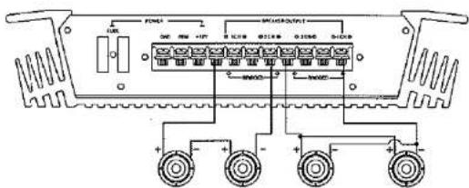
SERIAL WIRING
20
© Toxic 2005
Toxic®
BRIDGE MODE 2 CHANNEL AMPLIFIER
For increasing the output power, the amplifier can be run in bridge mode. The minimum speaker impedance may be 4 Ohm. When running in bridge mode, only mono replay is possible.
Bridge operation with 1 loudspeaker:

Bridge operation with 2 loudspeakers (4 ohm) in series connection:

Bridge operation with 2 loudspeakers (8 ohm) in parallel connection:

21
© Toxic 2005
Toxic®
TRI-MODE
If you want to use a subwoofer or centre speaker in stereo mode, you also can connect them in bridge operation to the speaker terminals. However, consider that in this case an additional passive crossover network (12 dB slope) is necessary because neither the subwoofer (optimal frequency band up to 150 Hz) nor the centre speaker (200 Hz - 6 KHz) can operate with full frequency band.
In tri-mode operation, only 4 ohm speakers for the left and right channel side should be used. 8 ohm are recommended as impedance for the third speaker, 4 ohm are also possible.
Subwoofers in tri-mode operation should be without case (free-air subwoofer). For achieving the best result, you can (on a trial basis) change the subwoofer's polarity. This should be done if it results into a more powerful bass. When using a subwoofer as a third speaker, the two other loudspeakers should be relieved from the deep frequency range of the subwoofer. For this, a 6 dB high pass filter is recommended, i.e. a condenser is put into the wiring of the speaker. Thus the sound of the relieved loudspeakers often becomes more transparent and power rating of the speaker is higher.
Tri-mode with subwoofer for 4-channel amplifiers:
Tri-mode with centre loudspeaker for 4-channel amplifiers:
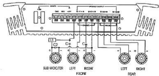
22
© Toxic 2005
Toxic®

Tri-mode with subwoofer for 2-channel amplifiers:
Tri-mode with center loudspeaker for 2-channel amplifiers:

23
© Toxic 2005
Toxic®

The following component values are recommended:
$$ C = \text { condenser } / L = \text { coil } $$
$$ C = 3 3 0 \mathrm{uF} \text { bipolar capacitor } $$
$$ L 1 = 1 0 \mathrm{mH} \quad C 1 = 1 0 0 \mathrm{uF} \text { for } 4 \text { ohm subwoofer } $$
$$ L 1 = 1 5 \mathrm{mH} \quad C 1 = 1 0 0 \mathrm{uF} \text { for } 8 \text { ohm subwoofer } $$
$$ L 2 = 9 \mathrm{mH} \quad C 2 = 6 8 \mathrm{uF} \text { for } 8 \text { ohm centre speaker } $$
$$ L = 0, 3 \mathrm{mH} \quad C 3 = 2. 2 \mathrm{uF} $$
Toxic
GND (-) = GROUND CONNECTION
Connect the Gnd terminal to the chassis ground of your car and take care of best electric and mechanic contact. In doing so, drill a hole into the car chassis near the amplifier, then remove colour, dirt or any other substance from the ground point. After that, fasten the cable end with the ring terminal by using a screw. Ensure that the ground connection is as short as possible and that the cable diameter is sufficient (min. 6mm²). Route the ground cables from the radio and all other equipment parts, like equalizer, active crossover network or other amplifiers, to the same ground point.
BATT (+) = POWER SUPPLY
Connect the Batt terminal to the positive pole of the battery with a lead cable and add a fuse into the power cable in a distance of not more than 30 cm from the battery. The lead cable's diameter should be at least 10mm² for a length of 3m and 16mm² for a lenght of 6m.
REM (ON / OFF) = REMOTE CONTROL
Connect the Rem terminal to the automatic antenna connector of your car radio. Now when turning on and off your car radio, the amplifier automatically switches on and off. A cable diameter of 0.5mm ^2 is sufficient.
ON = LED POWER INDICATOR
After the orderly connection of the three power terminals, the LED indicator shines green and goes out with "off".
PROTECT = LED PROTECTION INDICATOR
This set is equipped with an overload protection. Immediately upon overloading (due to short circuit or much increased temperature) the overload protection is activated, and the red LED indicator is shining. Through this, the amplifier is protected against damage. In case of thermal protection a certain short cooling time must be allowed after which the amplifier automatically resumes operation.
Toxic®
FUSE
The amplifier is equipped with a plug-in auto fuse protecting set against fault conditions. Do not use a fuse with a higher value and never bridge the fuse over, as this may lead to non-reparable damage so that any claim for warranty is denied.
GAIN = INPUT LEVEL CONTROL
The input level control allows the system to work well within a wide range of output levels. Choose the adjustment in the way that you achieve a sound most possibly without any distortion. As a guideline the following procedure is recommended:
If you use several amplifiers, the adjustment has to be made for each set separately. Tune in the volume of your car radio to 2/3 of the maximum volume. Now turn the gain control of the amplifier from "min" to "max" direction until you can hear distortions. Then turn the level control a little back to "min". The gain control adjustment is finished now.
When using a 4-channel amplifier, make this adjustment separately for channel 1/2 and channel 3/4.
Attention: If you use 2 ohm speakers in stereo mode, tri-mode or 4 ohm speakers in bridge mode and the overload protection is triggered out, turn the gain control to "min" direction, until the operation is free of trouble.
LOW PASS / HIGH PASS VARIABLE CROSSOVER
If a subwoofer has been connected to the amplifier, this loudspeaker can be run through a low/high pass filter on an optimum frequency range. For this purpose, frequency has to be turned to 40 Hz or 240 Hz according to selectable switch. The crossover frequency to be chosen in each case mainly depends on the cone size of the other car speakers.
BASS-BOOST
At 45 Hz the bass performance can be increased by 6 dB or 12 dB.
Toxic®
OPERATING PROCEDURE
After the amplifier has been installed and all connections have been made carefully and secure, turn the radio on so that the amplifier is switched on automatically. After a short power-on period, the amplifier reaches its full performance.
Now turn up the volume slowly, using the volume control of the radio. If there is no sound or only a distorted replay, switch off the radio immediately - the amplifier will also switch off automatically - and check if all connections have been made correctly.
HOW TO PROCEED IN CASE OF FAULTS
No function
The connection cable is not connected correctly (= terminals Batt/Gnd/Rem). Ensure that all connections have electric and mechanic contact and that the jacket has been removed. The fuse is defective - pay attention to the correct value of a new fuse!
No sound
Speaker cables or speaker plugs are not connected correctly.
No sound / green LED shines
The plus and minus wires of the speaker cables have contact, thus eliminate the short circuit.
If you use a 2 ohm speaker in stereo mode, a 4 ohm speaker in bridge mode or tri-mode and the set is overloaded, then turn the gain control to "min" until the operation is free of trouble.
One channel without function
The balance control is not in centre position, thus correct the position. The speaker or its lead is defective, so check the speaker, lead and connections.
Toxic®
Poor sound quality (distortions)
The speakers are overloaded, therefore turn down the volume level and check the volume control positions.
No stereo sound and a weak bass
Speaker cables (+) and (-) are mixed up, unit wired out of phase.
INTERFERENCE
All cables are source of interference or gather them. The power cable and Cinch/RCA audio cable are very prone to interference; the remote cables are less prone. There is often interference caused by the generator (piping), ignition (crackling) or other car electronic parts. Most of these problems can be eliminated by correct and careful cabling. In doing so, there are the following guidelines:
- Use only a shielded audio cables for the wiring between "low level in" of the amplifier and RCA or DIN outputs of the radio.
- Lay the signal, speaker and power cables separately with enough distance from another and also from any other car cable. If not possible, you can lay the circuit and ground cable together with the serial cables. Audio and speaker cable should be as far away from these as possible. The Rem cable to the automatic antenna output of the radio can be laid together with the signal cables.
- Avoid ground loops by laying the ground wiring of all components to a centre point in a star-like way. You can find the best central point i measuring the voltage directly at the battery. Now compare this voltage value with the chosen ground point and the (+) terminal of the amplifier. If the measured voltage is only less different, you have found the correct central. Otherwise you have to look for another point. You should measure with the ignition being switched on and additionally switched on consumers (rear window heating, light etc).
Toxic®
- If there are pickups from external electrical sources into the speaker cables, divide the core leads and twist them together.
- If there are noises from the car electrics, add an interference suppression choke into the power wiring.
- If there are humming noises, use thicker ground cables or add further ground cables to the chassis.
- To reduce contact resistance and bad and loose contacts, please tin the cable ends or use multicore cable ends, space terminals or others. Gold-plated spade terminals are free of corrosion and have the lowest contact resistance.
- Should all these measures be without any success, the use of a ground loop isolator may solve the problem.
WE WANT YOU LISTENING FOR A LIFETIME
Used wisely, your new sound equipment will provide a lifetime of fun and enjoyment. Since hearing damage from loud noise is often undetectable until it is too late, we recommend you to avoid prolonged exposure to excessive noise.
Technische Daten / Specifications :
| Technische Daten Specifications | TX-400N | TX-600N | TX-800N | TX-1200N | TX-1500N | TX-1600N |
| Max. Power | 400W | 600W | 800W | 1200W | 1500W | 1600W |
| Max. Watt pro Kanal Max. power per Channel | 2 x 200W | 2 x 300W | 4 x 200W | 4 x 300W | 2 x 750W | 4 x 400W |
| S/N Ratio Switchable | 100 dB | 100 dB | 100dB | 100dB | 100dB | 100dB |
| Frequenzgang Frequency response | 10 Hz - 40 KHz | 10 Hz - 40 KHz | 10 Hz - 40 KHz | 10 Hz - 40 KHz | 10 Hz - 40 KHz | 10 Hz - 40 KHz |
| THD | 0.05% | 0.05 % | 0.05 % | 0.05 % | 0.05 % | 0.05 % |
| Kanal Trennung Channel separation | 76 dB | 76 dB | 76 dB | 76 dB | 76 dB | 76 dB |
| Hoch- and Tiefpass High and lowpass | 40 Hz - 240 Hz | 40 Hz - 240 Hz | 40 Hz - 240 Hz | 40 Hz - 240 Hz | 40 Hz - 240 Hz | 40 Hz - 240 Hz |
| Dämpfungsfaktor Damping factor | 180 | 180 | 180 | 180 | 180 | 180 |
| Bass Boost | 0/6/12 dB | 0/6/12 dB | 0/6/12 dB | 0/6/12 dB | 0/6/12 dB | 0/6/12 dB |
| Abmessungen Dimensions | 226 x 282 x 63 | 256 x 282 x 63 | 316 x 282 x 63 | 356 x 282 x 63 | 536 x 282 x 63 | 456 x 282 x 63 |
- TOXIC Series
- TX-400N
- TX-600N
- TX-800N
- TX-1200N
- TX-1500N
- TX-1600N
- Toxic®
- EINFÜHRUNG
- EINBAU-HINWEISE
- EINBAU
- Achtung:
- LOW LEVEL EINGANG = CINCH/RCA EINGÄNGE
- LINE OUT
- LAUTSPRECHER ANSCHLÜSSE
- 4-KANAL
- 2-KANAL
- STEREO-MODUS
- BRÜCKEN-MODUS 4-KANAL-VERSTÄRKER
- Toxic
- BRÜCKEN-MODUS 2-KANAL-VERSTÄRKER
- TRI-MODE
- BATT (+) = STROMANSCHLUSS
- REM (ON/OFF) = AUTOMATISCHE EINSCHALTLEITUNG
- ON = LED EINSCHALTANZEIGE
- PROTECT = LED SCHUTZ-ANZEIGE
- SICHERUNG
- GAIN = EINGANGS-LEVEL KONTROLLE
- TIEF PASS / HOCH PASS FREQUENZWEICHE
- BASS-BOOST
- INBETRIEBNAHME
- FEHLER BEHEBEN
- Keine Funktion
- Kein Klang
- Kein Klang - Grüne LED leuchtet
- Ein Kanal ohne Funktion
- Verzerrungen
- Kein Stereo-Sound und schwache Bässe
- Störungen (Interferenzen)
- WIR WOLLEN IHNEN EIN LEBENSLANGES HÖRVERGNÜGEN ERMÖGLICHEN
- INTRODUCTION
- INSTALLATION INSTRUCTIONS
- ATTENTION LOW LEVEL IN = CINCH / RCA INPUTS
- SPEAKER CONNECTIONS
- 4-Channel
- 2-Channel
- STEREO MODE
- BRIDGE MODE 4 CHANNEL AMPLIFIER
- BRIDGE MODE 2 CHANNEL AMPLIFIER
- GND (-) = GROUND CONNECTION
- BATT (+) = POWER SUPPLY
- REM (ON / OFF) = REMOTE CONTROL
- ON = LED POWER INDICATOR
- PROTECT = LED PROTECTION INDICATOR
- FUSE
- GAIN = INPUT LEVEL CONTROL
- LOW PASS / HIGH PASS VARIABLE CROSSOVER
- OPERATING PROCEDURE
- HOW TO PROCEED IN CASE OF FAULTS
- No function
- No sound
- No sound / green LED shines
- One channel without function
- INTERFERENCE
- WE WANT YOU LISTENING FOR A LIFETIME
Marque : Toxic
Modèle : TX-400
Catégorie : Autoradio