MODE D'EMPLOI EG-101 ROLAND
EG-101
GROOVEKEYBOARD
MIDI Implementation

Section 1 Receive data
Channel Voice Messages
Note off
| Status | 2nd byte |
| 8nH | kkH |
| 9nH | kkH |
| n = MIDL channel number | : 0H-FH (ch.1-ch.16) |
| kk = note number | : 00H-7FH (0-127) |
| vv = note off velocity | : 00H-7FH (0-127) |
| * Not received when Rx.NOTEMESSAGE = OFF (Initial value is ON) or when note number is outside limits. |
| * For Drum Parts, these messages are received when Rx.NOTE OFF = ON for each Instrument. |
| * The velocity values of Note Off messages are ignored. |
Note on
| Status | 2nd byte | 3rd byte |
| 9nH | kkH | vH |
| n = MIDI channel number | : 0H-FH (ch.1-ch.16) |
| kk = note number | : 00H-7FH (0-127) |
| vv = note on velocity | : 01H-7FH (1-127) |
| * Not received when Rx.NOTESMESSAGE = OFF. (Initial value is ON) |
| * For Drum Parts, not received when Rx.NOTEN=OFF for each Instrument. |
- Polyphonic Key Pressure
| Status | 2nd byte | 3rd byte |
| AnH | kkH | vwH |
| n = MIDI channel number | : 0H-FH (ch.1-ch.16) |
| kk = note number | : 00H-7FH (0-127) |
| vv = key pressure | : 00H-7FH (0-127) |
| * Not received when Rx.POLY PRESSURE (PAf) = OFF. (Initial value is ON) |
| * The resulting effect is determined by System Exclusive messages. With the initial settings, there will be no effect. |
Control Change
- When Rx.CONTROL CHANGE = OFF, all control change messages except for Channel Mode messages will be ignored.
- The value specified by a Control Change message will not be reset even by a Program Change, etc.
Bank Select (Controller number 0, 32)
| Status | 2nd byte | 3rd byte |
| BnH | 00H | mmH |
| BnH | 20H | IIH |
| n = MIDL channel number | : 0H-FH (ch.1-ch.16) |
| mm = Bank number MSB | : 00H-7FH (0 - 127), Initial Value = 00H |
| II = Bank number LSB | : 00H - 03H (MAP), Initial Value = 00H |
| * Not received when Rx.BANK SELECT = OFF. (Power-on default value is ON.) |
| *Bank number LSB will be handled as 00H regardless of the received value. However, when sending Bank Select messages, you have to send both the MSB (mmH) and LSB (IH, the value should be 00H) together. |
| * Bank Select processing will be suspended until a Program Change message is received. |
Modulation (Controller number 1)
| Status | 2nd byte | 3rd byte |
| BnH | 01H | yyH |
| n = MDI channel number | : 0H-FH (ch.1-ch.16) |
| v = Modulation depth | : 00H-7FH (0-127) |
| * Not received when Rx.MODULATION = OFF. (Initial value is ON) |
| * The resulting effect is determined by System Exclusive messages. With the initial settings, this is Pitch Modulation Depth. |
Portamento Time (Controller number 5)
| Status | 2nd byte | 3rd byte |
| BnH | 05H | vvH |
| n = MDI channel number | : 0H-FH (ch.1-ch.16) |
| vv = Portamento Time | : 00H-7FH (0-127), Initial value = 00H (0) |
| * | This adjusts the rate of pitch change when Portamento is ON or when using the Portamento Control. A value of 0 results in the fastest change. |
| ** |
| *** |
| **** |
Data Entry (Controller number 6, 38)
| Status | 2nd byte | 3rd byte |
| BnH | 06H | mmH |
| BnH | 26H | IIH |
| n = MIDI channel number : 0H-FH (ch.1-ch.16) |
| mm, II = the value of the parameter specified by RPN/NRPN |
| mm = MSB, II = LSB |
Volume (Controller number 7)
| Status | 2nd byte | 3rd byte |
| BnH | 07H | vvH |
| n = MIDI channel number | : 0H-FH (ch.1-ch.16) |
| vv = Volume | : 00H-7FH (0-127), Initial Value = 64H (100) |
| * Volume messages are used to adjust the volume balance of each Part
* Not received when Rx.VOLUME = OFF. (Initial value is ON) |
Pan (Controller number 10)
| Status | 2nd byte | 3rd byte |
| BnH | 0AH | vH |
| n = MIDI channel number | : 0H-FH (ch.1-ch.16) |
| vv = pan | : 00H-40H-7FH (Left-Center-Right), Initial Value = 40H (Center) |
| * The stereo position can be adjusted over 127 steps. |
| * For Rhythm Parts, this is a relative adjustment of each instrument's pan setting. |
| * Not received when Rx.PANPOT = OFF. (Initial value is ON) |
Expression (Controller number 11)
| Status | 2nd byte | 3rd byte |
| BnH | 0BH | vvH |
| n = MDI channel number | : 0H-FH (ch.1-ch.16) |
| vv = Expression | : 00H-7FH (0-127), Initial Value = 7FH (127) |
| * This adjusts the volume of a Part. It can be used independently from Volume messages. Expression messages are used for musical expression within a performance; e.g., expression pedal movements, crescendo and decrescendo.
* Not received when Rx.EXPRESSION = OFF. (Initial value is ON) |
Hold 1 (Controller number 64)
| Status | 2nd byte | 3rd byte |
| BnH | 40H | vvH |
| n = MIDI channel number : 0H-FH (ch.1-ch.16) |
| vv = Control value : 00H-7FH (0-127) |
| * Not received when Rx.HOLD1 = OFF. (Initial value is ON) |
Portamento (Controller number 65)
| Status | 2nd byte | 3rd byte |
| BnH | 41H | vH、 |
| n = MIDI channel number | : 0H-FH (ch.1-ch.16) |
| vv = Control value | : 00H-7FH (0-127) 0-63 = OFF, 64-127 = ON |
| * Not received when RxPORTAMENTO = OFF. (Initial value is ON) |
Sostenuto (Controller number 66)
Status 2nd byte 3rd byte
BnH 42H
0H-FH(ch.1-ch.16) 00H-7FH(0-127) 0 - 63 = OFF,64-127 ON
- Not received when Rx.SOSTENUTO = OFF. (Initial value is ON)
Soft (Controller number 67)
Status 2nd byte 3rd byte
BnH 43H
channel number
OH-FH (ch.1-ch.16)
vv = Control value
00H-7FH (0-127) 0-63 = OFF, 64-127 = ON
- Not received when Rx.SOFT = OFF. (Initial value is ON)
Portamento control (Controller number 84)
Status 2nd byte 3rd byte
BnH 54H
channel number
: 0H-FH (ch.1-ch.16)
kk = source note number
:00H-7FH(0-127)
-
A Note-on received immediately after a Portamento Control message will change continuously in pitch, starting from the pitch of the Source Note Number.
-
If a voice is already sounding for a note number identical to the Source Note Number, this voice will continue sounding (i.e., legato) and will, when the next Note-on is received, smoothly change to the pitch of that Note-on.
-
The rate of the pitch change caused by Portamento Control is determined by the Portamento Time value.
| Example 1. |
| On MIDI | Description | Result |
| 90 3C 40 | Note on C4 | C4 on |
| B0 54 3C | Portamento Control from C4 | no change |
| 90 40 40 | Note on E4 | glide from C4 to E4 |
| 80 3C 40 | Note off C4 | no change |
| 80 40 40 | Note off E4 | E4 off |
| Example 2. |
| On MIDI | Description | Result |
| B0 54 3C | Portamento Control from C4 | no change |
| 90 40 40 | Note on E4 | E4 is played with glide from C4 to E4 |
| 80 40 40 | Note off E4 | E4 off |
Effect 1 (Reverb Send Level) (Controller number 91)
Status 2nd byte 3rd byte
BnH 5BH
m - 1 0 ;
n = MIDI channel number
OH-FH (ch.1-ch.16)
= Reverb Send Level
: 00H-7FH (0-127), Initial Value = 28H (40)
- This message adjusts the Reverb Send Level of each Part.
Effect 3 (Chorus Send Level) (Controller number 93)
Status 2nd byte 3rd byte
BnH 5DH
wH
n = MIDI channel number
:0H-FH(ch.1-ch.16)
vv = Chorus Send Level
:00H-7FH(0-127),InitialValue = 00H (0)
- This message adjusts the Chorus Send Level of each Part.
NRPN MSB/LSB (Controller number 99, 98)
Status 2nd byte 3rd byte
BnH 63H mmH
BnH 62H IIH
n = MIDI channel number ; 0H-FH (ch.1-ch.16)
mm = upper byte of the parameter number specified by NRPN
= lower byte of the parameter number specified by NRPN
**NRPN**
The NRPN (Non Registered Parameter Number) message allows an extended range of control changes to be used. On this unit, NRPN messages can be used to modify sound parameters etc.
To use these messages, you must first use NRPN messages (Controller number 98 and 99, their order does not matter) to specify the parameter to be controlled, and then use Data Entry messages to specify the value of the specified parameter. Once an NRPN parameter has been specified, all Data Entry messages received on that channel will modify the value of that parameter. To prevent accidents, it is recommended that you set RPN Null (RPN Number = 7FH/7FH) when you have finished setting the value of the desired parameter. Refer to Section 4. Supplementary material "Examples of actual MIDI messages" (page 11). On this unit, Data entry LSB (Controller number 38) of NRPN is ignored, so it is no problem to send Data entry MSB (Controller number 6) only (without Data entry LSB).
On the EG-101, NRPN can be used to modify the following parameters.
| NRPNMSB LSB | Data entryMSB | Function and range |
| 01H 08H | mmH | Vibrato Rate (relative change)mm: 00H - 40H - 7FH (-64 - 0 - +63) |
| 01H 09H | mmH | Vibrato Depth (relative change)mm: 00H - 40H - 7FH (-64 - 0 - +63) |
| 01H 0AH | mmH | Vibrato Delay (relative change)mm: 00H - 40H - 7FH (-64 - 0 - +63) |
| 01H 20H | mmH | TVF Cutoff Frequency (relative change)mm: 00H - 40H - 7FH (-64 - 0 - +63) |
| 01H 21H | mmH | TVF Resonance (relative change)mm: 00H - 40H - 7FH (-64 - 0 - +63) |
| 01H 63H | mmH | TVF&TVA Envelope Attack Time (relative change)mm: 00H - 40H - 7FH (-64 - 0 - +63) |
| 01H 64H | mmH | TVF&TVA Envelope Decay Time (relative change)mm: 00H - 40H - 7FH (-64 - 0 - +63) |
| 01H 66H | mmH | TVF&TVA Envelope Release Time (relative change)mm: 00H - 40H - 7FH (-64 - 0 - +63) |
| 18H rrH | mmH | Drum Instrument Pitch Coarse (relative change)rr: Drum Instrument note numbermm: 00H - 40H - 7FH (-64 - 0 - +63 semitone) |
| 1AH rrH | mmH | Drum Instrument TVA Level (absolute change)rr: Drum Instrument note numbermm: 00H - 7FH (0 - max) |
| 1CH rrH | mmH | Drum Instrument Panpot (absolute change)rr: Drum Instrument note numbermm: 00H, 01H - 40H - 7FH (random, left-center-right) |
| 1DH rrH | mmH | Drum Instrument Reverb Send Level (absolute change)rr: Drum Instrument note numbermm: 00H - 7FH (0 - max) |
| 1EH rrH | mmH | Drum Instrument Chorus Send Level (absolute change)rr: Drum Instrument note numbermm: 00H - 7FH (0 - max) |
- Data entry LSB (IIH) is ignored.
- Parameters marked "relative change" will change relative to the preset value(40H).
- Parameters marked "absolute change" will be set to the absolute value of the parameter, regardless of the preset value.
RPN MSB/LSB (Controller number 101, 100)
Status 2no
2nd byte
3rd byte
65H
64H
H
OH-FH (ch.1-ch.16)
mm = upper byte of parameter number specified by RPN
ll = lower byte of parameter number specified by RPN
Change or Reset All Controller
**RPN**
The RPN (Registered Parameter Number) messages are expanded control changes, and each function of an RPN is described by the MIDI Standard.
To use these messages, you must first use RPN (Controller number 100 and 110, their order does not matter) to specify the parameter to be controlled, and then use Data Entry messages (Controller number 6, 38) to specify the value of the specified parameter. Once an RPN parameter has been specified, all Data Entry messages received on that channel will modify the value of that parameter. To prevent accidents, it is recommended that you set RPN Null (RPN Number = 7FH/7FH) when you have finished setting the value of the desired parameter. Refer to Section 4. "Examples of actual MIDI messages" (page 11).
On the EG-101, RPN can be used to modify the following parameters.
| RPNMSLB | Data entryMSLB | Explanation |
| 00H 00H | mmH -- | Pitch Bend Sensitivitymm: 00H-18H (0-24 semitones),Initial Value = 02H (2 semitones)ll: ignored (processed as 00H)specify up to 2 octaves in semitone steps |
| 00H 01H | mmH lIIH | Master Fine Tunningmm, ll: 00 00H - 40 00H - 7F 7FH (-100 - 0 - +99.99 cents),Initial Value = 40 00H (± 0 cent)Refer to 4. Supplementary material, "About tuning" (page 12). |
| 00H 02H | mmH -- | Master Coarse Tunningmm: 28H-40H-58H (-24 - 0 - +24 semitones),Initial Value = 40H (±0 semitone)ll: ignored (processed as 00H) |
| 7FH 7FH -- | -- | RPN nullSet condition where RPN and NRPN are unspecified. The dataentry messages after set RPN null will be ignored. (No Dataentry messages are required after RPN null).Settings already made will not change.mm, ll: ignored |
Program Change
Status 2nd byte
CnH ppH
n = MIDI channel number
OH-FH (ch.1-ch.16)
:00H-7FH(prog.1-prog.128)
-
Not received when Rx.PROGRAM CHANGE = OFF. (Initial value is ON)
-
After a Program Change message is received, the sound will change beginning with the next Note-on. Voices already sounding when the Program Change message was received will not be affected.
-
For Drum Parts, Program Change message will not be received on lower byte of the bank numbers (the value of Control Number 0 is other than 0 (OH)).
Channel Pressure
Status 2nd byte
DnH wH
n = MIDI channel number
OH-FH (ch.1-ch.16)
:00H-7FH(0-127)
Pitch Bend Change
Status
2nd byte
H
Vte
n = MIDI channel number
OH-FH (ch.1-ch.16)
:0000H-4000H-7F7FH(-8192-0-+8191)
■ Channel Mode Messages
All Sounds Off (Controller number 120)
Status 2nd byte 3rd byte
00H
n = MIDI channel number : 0H-FH (ch.1-ch.16)
- When this message is received, all currently-sounding notes on the corresponding channel will be turned off immediately.
- Reset All Controllers (Controller number 121)
Status 2nd byte 3rd byte
BnH 79H 00H
n = MIDI channel number : 0H-FH (ch.1-ch.16)
- When this message is received, the following controllers will be set to their reset values.
| Controller | Reset value |
| Pitch Bend Change | ±0 (center) |
| Polyphonic Key Pressure | 0 (off) |
| Channel Pressure | 0 (off) |
| Modulation | 0 (off) |
| Expression | 127 (max) |
| Hold 1 | 0 (off) |
| Portamento | 0 (off) |
| Sostenuto | 0 (off) |
| Soft | 0 (off) |
- Local On/Off (Controller number 122)
Status 2nd byte 3rd byte
BnH 7AH 00H
BnH 7AH 7FH
n = MIDI channel number : 0H-FH (ch.1-ch.16)
This parameter affects all the parts
When Local Off message is received, the generation board is disconnected from the keyboard but the messages received via Midi are still recognized and played.
*Regardless of the set channel, this message is sent to all parts.
All Notes Off (Controller number 123)
Status 2nd byte 3rd byte
BnH 7BH 00H
n = MIDl channel number : 0H-FH (ch.1-ch.16)
- When All Notes Off is received, all notes on the corresponding channel will be turned off. However if Hold 1 or Sostenuto is ON, the sound will be continued until these are turned off.
- OMNI OFF (Controller number 124)
Status 2nd byte 3rd byte
BnH 7CH 00H
n = MIDI channel number : 0H-FH (ch.1-ch.16)
- Omni Off is only recognize as "All Notes Off". Mode does not change.
OMNI ON (Controller number 125)
Status 2nd byte 3rd byte
BnH 7DH 00H
n = MIDI channel number : 0H-FH (ch.1-ch.16)
- Omni On is only recognize as "All Notes Off". Mode does not change.
- MONO (Controller number 126)
Status 2nd byte 3rd byte
BnH 7EH mmH
n = MIDI channel number : 0H-FH (ch.1-ch.16)
mm = mono number : 00H-10H (0-16)
- The same processing will be carried out as when All Sounds Off and All Notes Off is received, and the corresponding channel will be set to Mode 4 (M = 1) regardless of the value of "mono number."
POLY (Controller number 127)
Status 2nd byte 3rd byte
BnH 7FH 00H
n = MIDI channel number : 0H-FH (ch.1-ch.16)
- The same processing will be carried out as when All Sounds Off and All Notes Off is received, and the corresponding channel will be set to Mode 3.
System Realtime Message
Active Sensing
Status FEH
- When Active Sensing is received, the unit will begin monitoring the intervals of all further messages. While monitoring, if the interval between messages exceeds 420 ms, the same processing will be carried out as when All Sounds Off, All Notes Off and Reset All Controllers are received, and message interval monitoring will be halted.
Sequencer Start
Status FAH
- When "Sequencer Start" is received, the internal Recorder and/or the internal Arranger start according to the following table.
Sequencer Stop
Status FCH
- When "Sequencer Stop" is received, the internal Recorder and/or the internal arranger stop according to the following table.
Timing Clock
Status F8H
- When "Timing Clock" is received the internal recorder or the internal arranger is synchronized to an external clock according to the following table.
| Sync RX | Response | ○ Modulation (Controller number 1) |
| Internal
(Md1, Md4) | The Style or Song will neither start/stop nor follow the tempo of the external Timing Clock (F8) and "Start /Stop" (FA / FC) messages.
Md1 = Local ON - Md4 = Local OFF | Status | 2nd byte | 3rd byte |
| BnH | 01H | vvH |
| n=MIDI channel number | :0H - FH (ch.1 - ch.16) |
| vv=Modulation depth | :00H - 7FH (0 - 127) |
| Auto Arranger
(Md2, Md5) | The Arranger will Start/Stop on receiving FA/FC it will either follow its own Internal BPM tempo or it will automatically synchronize to the external BPM tempo, if F8 messages are received.
Md2 = Local ON - Md5 = Local OFF | ○ Portamento Time | (Controller number 5) |
| Status | 2nd byte | 3rd byte |
| BnH | 05H | vvH |
| Auto Song
(Md3, Md6) | The Song will Play/Stop on receiving FA/FC it will either follow its own Internal BPM tempo or it will automatically synchronize to the external BPM tempo, if F8 messages are received.
Md3 = Local ON - Md6 = Local OFF | n=MIDI channel number | :0H - FH (ch.1 - ch.16) |
| vv=Portamento Time | :00H - 7FH (0 - 127) |
| * This adjusts the rate of pitch change when Portamento is on or when using the Portamento Control. A value of 0 results in the fastest change. |
Section 2 Transmit data
■ Channel voice messages
Note off
Status 2nd byte 3rd byte 9nH kkH 00H
n=MIDI channel number :OH-FH(ch.1-ch.16)
kk=note number : 00H-7FH(0-127)
vv=velocity :00H(0)
Note on
Status 2nd byte 3rd byte 9nH kkH vvH
n=MIDI channel number :0H-FH (ch.1-ch.16)
kk=note number : 00H -7FH (0 - 127)
vv = veloicy :01H-7FH(1-127)
Control Change
Bank Select (Controller number 0,32)
Status 2nd byte 3rd byte
BnH 00H mmH
BnH 20H IIH
n=MIDI channel number :0H-FH(ch.1-ch.16)
mm=Bank number MSB:00H-7FH(0-127)
II=Bank number LSB :00H-02H (MAP)
Modulation (Controller number 1)
Status 2nd byte 3rd byte
BnH 01H
n=MIIDichannelnumber :0H-FH(ch.1-ch.16)
vv=Modulation depth : 00H - 7FH (0 - 127)
Portamento Time (Controller number 5)
Status 2nd byte 3rd byte
BnH 05H wH
n=MIDI channel number :0H-FH(ch.1-ch.16)
vv=Portamento Time :00H-7FH(0-127)
- This adjusts the rate of pitch change when Portamento is on or when using the Portamento Control. A value of 0 results in the fastest change.
Data Entry (Controller number 6,38)
Status 2nd byte 3rd byte
BnH 06H mmH
BnH 26H H
n=MIDI channel number :0H-FH(ch.1-ch.16)
mm,II= the value of the parameter specified by RPN/NRPN
Pan
Status 2nd byte 3rd byte
BnH 0AH vH
n=MI DI channel number
VW=pan
(Left - Center - Right)
- The stereo position can be adjusted over 127 steps.
Expression(Controller number 11)
Status 2nd byte 3rd byte
BnH OBH vH
n=MIDL channel number :0H-FH(ch.1-ch.16)
vv=Expression : 00H - 7FH (0 - 127)
Hold 1
Status 2nd byte 3rd byte
BnH 40H
n=MIDI channel number
vv=Control value
(Controller number 64)
-
:0H-FH(ch.1-ch.16)
:00H-7FH(0-127) 0-63=OFF 64-127=ON
Effect 1 (Reverb Send Level)
Status 2nd byte 3rd byte
BnH 5BH
n=MIDI channel number
vv=Control value
(Controller number 91)
VH
:OH-FH(ch.1-ch.16)
:00H-7FH(0-127)
Initial value = 28H (40)
| Effect 3 (Chorus Send Level) |
| Status | 2nd byte | 3rd byte |
| BnH | 5DH | vVH |
| n=MIDI channel number | :0H-FH (ch.1-ch.16) |
| vv=Control value | :00H-7FH (0-127) |
number 93)
System Realtime Messages
Active Sensing
Status
FEH
| ○NRPN MSB/LSB | (Controller number 99,98) |
| Status | 2nd byte | 3rd byte |
| BnH | 63H | mmH | |
| BnH | 62H | IIH | |
| n=MIDI channel number :OH-FH(ch,1-ch,16) |
| mm=upper byte of the parameter number specified by NRPN |
| Illower byte of the parameter number specified by NRPN |
**NRPN**
The NRPN (Non Registered Parameter Number) message allows an extended range of control changes to be used, letting you use control functions which are not defined in the MIDI Specification.
NRPNs provide a great deal of freedom, and can be used with any manufacturer's devices. As a result, any particular parameter number can easily mean one thing when used for a certain device, and mean something completely different on another device.
Note that RPNs and NRPNs require that a multiple number of messages be processed in the correct order. However, a majority of the sequencers currently on the market cannot always be relied on to consistently send messages in the proper order if the messages are located at almost exactly the same point in time.
On the EG-101 instruments, NRPN can be used to modify the following parameters.
| NRPN | Data entry | |
| MSB LSB | MSB | Function and range |
| 01H 20H | mmH | TVF Cutoff Frequency (relative change) |
| mm: 00H - 40H - 7FH (-64 - 0 - +63) |
| 01H 21H | mmH | TVF Resonance (relative change) |
| mm: 00H - 40H - 7FH (-64 - 0 - +63) |
| Program Change |
| Status | 2nd byte |
| CnH | ppH |
| n=MIDI channel number | :0H-FH(ch.1-ch.16) |
| pp=Program number | :00H-7FH(prog.1-prog.128) |
| Pitch Bend Change |
| Status | 2nd byte | 3rd byte |
| EnH | IIH | mmH |
| n = MIDI channel number | : 0H-FH (ch.1-ch.16) |
| mm, II = Pitch Bend value | : 00 00H - 40 00H - 7F 7FH (-8192 - 0 - +8191) |
Transmitted about every 250ms.
| ○ Sequencer Start Status |
| FAH |
- This message is transmitted when the internal sequencer is started.
| ○ Sequencer Stop Status |
| FCH |
- This message is transmitted when the internal sequencer is stopped.
| System Exclusive Messages |
| Status | Data byte |
| FOH | iH, ddH, ..., eeH |
| FOH | : System Exclusive Message status |
| ii = ID number | : an ID number (manufacturer ID) to indicate the manufacturer whose Exclusive message this is. Roland's manufacturer ID is 41H. |
| ID numbers 7EH and 7FH are extensions of the MIDI standard; Universal Non-realtime Messages (7EH) and Universal Realtime Messages (7FH). |
| dd, ..., ee = data | : 00H - 7FH (0 - 127) |
| F7H | : EOX (End Of Exclusive) |
The System Exclusive Messages Transmitted and received by the EG-101 are: Data transmission
Section 3 Individual Parameter Transmission (Model ID=00H 18H)
Individual Parameter Transmission transmits data (or requests data) for one parameter as one exclusive message (one packet of "F0....F7").
In Individual Parameter Transmission, you must use the Address and Size listed in the following "Parameter Address Map". Addresses marked at "#" cannot be used as starting addresses.
Patch parameters
Patch common parameters
Model ID=00H 18H
| Address(H) | Size(H) | Data(H) | Parameter | Description | Default Value (H) | Description |
| 40 00 00 | 00 00 04 | 0018 - 07E8 | MASTER TUNE | -100.0 - +100.0 (cent) | 00 04 00 00 | 0 (cent) |
| 40 00 01# | | | | Use nibbled data. | | |
| 40 00 02# | | | | | | |
| 40 00 03# | | | | | | |
| * Refer to section 4. Supplementary material, "About tuning" (page 12). |
| 40 00 04 | 00 00 01 | 00 - 7F | MASTER VOLUME | 0 - 127 (= F0 7F 7F 04 01 00 vv F7 ) | 7F | 127 |
| 40 00 05 | 00 00 01 | 28 - 58 | MASTER KEY-SHIFT | -24 - +24 (semitones) | 40 | 0(semitones) |
| 40 00 06 | 00 00 01 | 01 - 7F | MASTER PAN | -63 (LEFT) - +63 (RIGHT) | 40 | 0 (CENTER) |
| 40 01 30 | 00 00 01 | 00 - 07 | REVERB MACRO | 00: Room 1 | 04 | Hall 2 |
| 01: Room 2 |
| 02: Room 3 |
| 03: Hall 1 |
| 04: Hall 2 |
| 05: Plate |
| 06: Delay |
| 07: Panning Delay |
| 40 01 31 | 00 00 01 | 00 - 07 | REVERB CHARACTER | 0 - 7 | 04 | 4 |
| 40 01 32 | 00 00 01 | 00 - 07 | REVERB PRE-LPF | 0 - 7 | 00 | 0 |
| 40 01 33 | 00 00 01 | 00 - 7F | REVERB LEVEL | 0 - 127 | 40 | 64 |
| 40 01 34 | 00 00 01 | 00 - 7F | REVERB TIME | 0 - 127 | 40 | 64 |
| 40 01 35 | 00 00 01 | 00 - 7F | REVERB DELAY FEEDBACK | 0 - 127 | 00 | 0 |
| 40 01 36 | 00 00 01 | 00 - 7F | REVERB SEND LEVEL TO CHORUS | 0 - 127 | 00 | 0 |
- REVERB MACRO is a macro parameter that allows global setting of reverb parameters. When you select the reverb type with REVERB MACRO, each reverb parameter will be set to the most suitable value.
- REVERB CHARACTER is a parameter that changes the reverb algorithm. The value of REVERB CHARACTER corresponds to the REVERB MACRO of the same number.
| 40 01 38 | 00 00 01 | 00 - 07 | CHORUS MACRO | 00: Chorus 1
01: Chorus 2
02: Chorus 3
03: Chorus 4
04: Feedback Chorus
05: Flanger
06: Short Delay
07: Short Delay(FB) | 02 | Chorus 3 |
| 40 01 39 | 00 00 01 | 00 - 07 | CHORUS PRE-LPF | 0-7 | 00 | 0 |
| 40 01 3A | 00 00 01 | 00 - 7F | CHORUS LEVEL | 0-127 | 40 | 64 |
| 40 01 3B | 00 00 01 | 00 - 7F | CHORUS FEEDBACK | 0-127 | 08 | 8 |
| 40 01 3C | 00 00 01 | 00 - 7F | CHORUS DELAY | 0-127 | 50 | 80 |
| 40 01 3D | 00 00 01 | 00 - 7F | CHORUS RATE | 0-127 | 03 | 3 |
| 40 01 3E | 00 00 01 | 00 - 7F | CHORUS DEPTH | 0-127 | 13 | 19 |
| 40 01 3F | 00 00 01 | 00 - 7F | CHORUS SEND LEVEL TO REVERB | 0-127 | 00 | 0 |
- CHORUS MACRO is a macro parameter that allows global setting of chorus parameters. When you use CHORUS MACRO to select the chorus type, each chorus parameter will be set to the most suitable value.
The relation between Part number and Block number is as follows.
x...BLOCK NUMBER (0 - F), Part 1 (default MldCh = 1) x=1
Part 2 (default MIDlch = 2) x=2
Part 9 (default MIDlch = 9) x = 9
Part10 (default MIDlch =10) x = 0
Part11 (default MIldCh=11) x=A D:13 14
Part12 (default MIDich = 12) x=8
Part16 (default MIDlch=16) x=F
n... MIDI channel number (0 - F) of the BLOCK.
In the following map, the control numbers of the control changes are indicated as CC#.
| 40 1x 00 | 00 00 02 | 00 - 7F | TONE NUMBER | CC#00 VALUE 0 - 127 | 00 | 0 |
| 40 1x 01# | | 00 - 7F | | P.C. VALUE 1 - 128 | 00 | 1 |
| 40 1x 02 | 00 00 01 | 00 - 10 | Rx. CHANNEL | 1 - 16, OFF | | Same as the Part Number |
| 40 1x 03 | 00 00 01 | 00 - 01 | Rx. PITCH BEND | OFF / ON | 01 | ON |
| 40 1x 04 | 00 00 01 | 00 - 01 | Rx. CH PRESSURE(CAF) | OFF / ON | 01 | ON |
| 40 1x 05 | 00 00 01 | 00 - 01 | Rx. PROGRAM CHANGE | OFF / ON | 01 | ON |
| 40 1x 06 | 00 00 01 | 00 - 01 | Rx. CONTROL CHANGE | OFF / ON | 01 | ON |
| 40 1x 07 | 00 00 01 | 00 - 01 | Rx. POLY PRESSURE(PAF) | OFF / ON | 01 | ON |
| 40 1x 08 | 00 00 01 | 00 - 01 | Rx. NOTEMESSAGE | OFF / ON | 01 | ON |
| 40 1x 09 | 00 00 01 | 00 - 01 | Rx. RPN | OFF / ON | 01 | ON |
| 40 1x 0A | 00 00 01 | 00 - 01 | Rx. NRPN | OFF / ON | 00 | OFF |
| 40 1x 0B | 00 00 01 | 00 - 01 | Rx. MODULATION | OFF / ON | 01 | ON |
| 40 1x 0C | 00 00 01 | 00 - 01 | Rx. VOLUME | OFF / ON | 01 | ON |
| 40 1x 0D | 00 00 01 | 00 - 01 | Rx. PANPOT | OFF / ON | 01 | ON |
| 40 1x 0E | 00 00 01 | 00 - 01 | Rx. EXPRESSION | OFF / ON | 01 | ON |
| 40 1x 0F | 00 00 01 | 00 - 01 | Rx. HOLD1 | OFF / ON | 01 | ON |
| 40 1x 10 | 00 00 01 | 00 - 01 | Rx. PORTAMENTO | OFF / ON | 01 | ON |
| 40 1x 11 | 00 00 01 | 00 - 01 | Rx. SOSTENUTO | OFF / ON | 01 | ON |
| 40 1x 12 | 00 00 01 | 00 - 01 | Rx. SOFT | OFF / ON | 01 | ON |
| Address(H) | Size(H) | Data(H) | Parameter | Description | Default Value (H) | Description |
| 40 1x 13 | 00 00 01 | 00 - 01 | MONO/POLY MODE | Mono / Poly (=CC# 126.01 / CC# 127.00) | 01 | Poly |
| 40 1x 14 | 00 00 01 | 00 - 02 | ASSIGN MODE | 0 = SINGLE 1 = LIMITED-MULTI 2 = FULL-MULTI | | |
| * ASSIGN MODE is the parameter that determines how voice assignment will be handled when sounds overlap on identical note numbers in the same channel (i.e., repeatedly struck notes). This is initialized to a mode suitable for each Part, so for general purposes there is no need to change this. |
| 40 1x 15 | 00 00 01 | 00 - 02 | USE FOR RHYTHM PART | 0 = OFF 1 = MAP1 2 = MAP2 | 00 at x0 01 at x=0 | OFF (Normal Part) MAP1 (Drum Part) |
| * This parameter sets the Drum Map of the Part used as the Drum Part. This unit can simultaneously (in different Parts) use up to two Drum Maps (MAP1, MAP2). With the initial settings, Part10 (MIDI CH=10. x=0) is set to MAP1 (1), and other Parts are set to normal instrumental Parts (OFF(0)). |
| 40 1x 16 | 00 00 01 | 28 - 58 | PITCH KEY SHIFT | -24 - +24 (semitones) | 40 | 0 (semitones) |
| 40 1x 17 | 00 00 02 | 08 - F8 | PITCH OFFSET FINE | -12.0 - +12.0 (Hz) Use nibbled data. | 08.00 | 0 (Hz) |
| 40 1x 18# | | | | | | |
| * PITCH OFFSET FINE allows you to alter, by a specified frequency amount, the pitch of which notes will sound. This parameter differs from the conventional Fine Tuning (RPN #1) parameter in that the amount of frequency alteration (in Hertz) will be identical no matter which note is played. When a multiple number of Parts, each of which has been given a different setting for PITCH OFFSET FINE, are sounded by means of an identical note number, you can obtain a Celeste effect. |
| 40 1x 19 | 00 00 01 | 00 - 7F | PART LEVEL | 0 - 127 (=CC# 7) | 64 | 100 |
| 40 1x 1A | 00 00 01 | 00 - 7F | VELOCITY SENSE DEPTH | 0 - 127 | 40 | 64 |
| 40 1x 1B | 00 00 01 | 00 - 7F | VELOCITY SENSE OFFSET | 0 - 127 | 40 | 64 |
| 40 1x 1C | 00 00 01 | 00 - 7F | PART PANPOT | -64(RANDOM), -63(LEFT) + +63(RIGHT) (=CC# 10, except RANDOM) | 40 | 0 (CENTER) |
| 40 1x 1D | 00 00 01 | 00 - 7F | KEYBOARD RANGE LOW | (C-1) - (G9) | 00 | C-1 |
| 40 1x 1E | 00 00 01 | 00 - 7F | KEYBOARD RANGE HIGH | (C-1) - (G9) | 7F | G 9 |
| 40 1x 1F | 00 00 01 | 00 - 5F | CC1 CONTROLLER NUMBER | 0 - 95 | 10 | 16 |
| 40 1x 20 | 00 00 01 | 00 - 5F | CC2 CONTROLLER NUMBER | 0 - 95 | 11 | 17 |
| 40 1x 21 | 00 00 01 | 00 - 7F | CHORUS SEND LEVEL | 0 - 127 (=CC# 93) | 00 | 0 |
| 40 1x 22 | 00 00 01 | 00 - 7F | REVERB SEND LEVEL | 0 - 127 (=CC# 91) | 28 | 40 |
| 40 1x 23 | 00 00 01 | 00 - 01 | Rx.BANK SELECT | OFF / ON | 01(00*) | ON(OFF*) |
| 40 1x 30 | 00 00 01 | 00 - 7F | TONE MODIFY1 Vibrato Rate | -64 - +63 (=NRPN# 8) | 40 | 0 |
| 40 1x 31 | 00 00 01 | 00 - 7F | TONE MODIFY2 Vibrato Depth | -64 - +63 (=NRPN# 9) | 40 | 0 |
| 40 1x 32 | 00 00 01 | 00 - 7F | TONE MODIFY3 TVF Cutoff Freq. | -64 - +63 (=NRPN# 32) | 40 | 0 |
| 40 1x 33 | 00 00 01 | 00 - 7F | TONE MODIFY4 TVF Resonance | -64 - +63 (=NRPN# 33) | 40 | 0 |
| 40 1x 34 | 00 00 01 | 00 - 7F | TONE MODIFY5 TVF&IA Envattack | -64 - +63 (=NRPN# 99) | 40 | 0 |
| 40 1x 35 | 00 00 01 | 00 - 7F | TONE MODIFY6 TVF&IA Env.decay | -64 - +63 (=NRPN# 100) | 40 | 0 |
| 40 1x 36 | 00 00 01 | 00 - 7F | TONE MODIFY7 TVF&IA Env/release | -64 - +63 (=NRPN# 102) | 40 | 0 |
| 40 1x 37 | 00 00 01 | 00 - 7F | TONE MODIFY8 Vibrato Delay | -64 - +63 (=NRPN# 10) | 40 | 0 |
| 40 1x 40 | 00 00 OC | 00 - 7F | SCALE TUNING C | -64 - +63 (cent) | 40 | 0 (cent) |
| 40 1x 41# | | 00 - 7F | SCALE TUNING C# | -64 - +63 (cent) | 40 | 0 (cent) |
| 40 1x 42# | | 00 - 7F | SCALE TUNING D | -64 - +63 (cent) | 40 | 0 (cent) |
| 40 1x 43# | | 00 - 7F | SCALE TUNING D# | -64 - +63 (cent) | 40 | 0 (cent) |
| 40 1x 44# | | 00 - 7F | SCALE TUNING E | -64 - +63 (cent) | 40 | 0 (cent) |
| 40 1x 45# | | 00 - 7F | SCALE TUNING F | -64 - +63 (cent) | 40 | 0 (cent) |
| 40 1x 46# | | 00 - 7F | SCALE TUNING F# | -64 - +63 (cent) | 40 | 0 (cent) |
| 40 1x 47# | | 00 - 7F | SCALE TUNING G | -64 - +63 (cent) | 40 | 0 (cent) |
| 40 1x 48# | | 00 - 7F | SCALE TUNING G# | -64 - +63 (cent) | 40 | 0 (cent) |
| 40 1x 49# | | 00 - 7F | SCALE TUNING A | -64 - +63 (cent) | 40 | 0 (cent) |
| 40 1x 4A# | | 00 - 7F | SCALE TUNING A# | -64 - +63 (cent) | 40 | 0 (cent) |
| 40 1x 4B# | | 00 - 7F | SCALE TUNING B | -64 - +63 (cent) | 40 | 0 (cent) |
| * SCALE TUNING is a function that allows fine adjustment to the pitch of each note in the octave. The pitch of each identically-named note in all octaves will change simultaneously. A setting of ± 0 cent (40H) is equal temperament (page 12). |
| 40 2x 00 | 00 00 01 | 28 - 58 | MOD PITCH CONTROL | -24 - +24 (semitones) | 40 | 0 (semitones) |
| 40 2x 01 | 00 00 01 | 00 - 7F | MOD TVF CUTOFF CONTROL | -9600 - +9500 (cent) | 40 | 0 (cent) |
| 40 2x 02 | 00 00 01 | 00 - 7F | MOD AMPLITUDE CONTROL | -100.0 - +100.0 (%) | 40 | 0 (%) |
| 40 2x 03 | 00 00 01 | 00 - 7F | MOD LFO1 RATE CONTROL | -10.0 - +10.0 (Hz) | 40 | 0 (Hz) |
| 40 2x 04 | 00 00 01 | 00 - 7F | MOD LFO1 PITCH DEPTH | 0 - 600 (cent) | 0A | 10 (cent) |
| 40 2x 05 | 00 00 01 | 00 - 7F | MOD LFO1 TVF DEPTH | 0 - 2400 (cent) | 00 | 0 (cent) |
| 40 2x 06 | 00 00 01 | 00 - 7F | MOD LFO1 TVA DEPTH | 0 - 100.0 (%) | 00 | 0 (%) |
| 40 2x 07 | 00 00 01 | 00 - 7F | MOD LFO2 RATE CONTROL | -10.0 - +10.0 (Hz) | 40 | 0 (Hz) |
| 40 2x 08 | 00 00 01 | 00 - 7F | MOD LFO2 PITCH DEPTH | 0 - 600 (cent) | 00 | 0 (cent) |
| 40 2x 09 | 00 00 01 | 00 - 7F | MOD LFO2 TVF DEPTH | 0 - 2400 (cent) | 00 | 0 (cent) |
| 40 2x 1A | 00 00 01 | 00 - 7F | MOD LFO2 TVA DEPTH | 0 - 100.0 (%) | 00 | 0 (%) |
| 40 2x 10 | 00 00 01 | 40 - 58 | BEND PITCH CONTROL | 0 - 24 (semitones) | 42 | 2 (semitones) |
| 40 2x 11 | 00 00 01 | 00 - 7F | BEND TVF CUTOFF CONTROL | -9600 - +9500 (cent) | 40 | 0 (cent) |
| 40 2x 12 | 00 00 01 | 00 - 7F | BEND AMPLITUDE CONTROL | -100.0 - +100.0 (%) | 40 | 0 (%) |
| 40 2x 13 | 00 00 01 | 00 - 7F | BEND LFO1 RATE CONTROL | -10.0 - +10.0 (Hz) | 40 | 0 (Hz) |
| 40 2x 14 | 00 00 01 | 00 - 7F | BEND LFO1 PITCH DEPTH | 0 - 600 (cent) | 00 | 0 (cent) |
| 40 2x 15 | 00 00 01 | 00 - 7F | BEND LFO1 TVF DEPTH | 0 - 2400 (cent) | 00 | 0 (cent) |
| 40 2x 16 | 00 00 01 | 00 - 7F | BEND LFO1 TVA DEPTH | 0 - 100.0 (%) | 00 | 0 (%) |
| 40 2x 17 | 00 00 01 | 00 - 7F | BEND LFO2 RATE CONTROL | -10.0 - +10.0 (Hz) | 40 | 0 (Hz) |
| 40 2x 18 | 00 00 01 | 00 - 7F | BEND LFO2 PITCH DEPTH | 0 - 600 (cent) | 00 | 0 (cent) |
| 40 2x 19 | 00 00 01 | 00 - 7F | BEND LFO2 TVF DEPTH | 0 - 2400 (cent) | 00 | 0 (cent) |
| 40 2x 1A | 00 00 01 | 00 - 7F | BEND LFO2 TVA DEPTH | 0 - 100.0 (%) | 00 | 0 (%) |
| 40 2x 20 | 00 00 01 | 28 - 58 | | CAF PITCH CONTROL | -24 - +24 (semitones) | 40 |
| 40 2x 21 | 00 00 01 | 00 - 7F | | CAF TVF CUTOFF CONTROL | -9600 - +9600 (cent) | 40 |
| 40 2x 22 | 00 00 01 | 00 - 7F | | CAF AMPLITUDE CONTROL | -100.0 - +100.0 (%) | 40 |
| 40 2x 23 | 00 00 01 | 00 - 7F | | CAF LFO1 RATE CONTROL | -10.0 - +10.0 (Hz) | 40 |
| 40 2x 24 | 00 00 01 | 00 - 7F | | CAF LFO1 PITCH DEPTH | 0 - 600 (cent) | 00 |
| 40 2x 25 | 00 00 01 | 00 - 7F | | CAF LFO1 TVF DEPTH | 0 - 2400 (cent) | 00 |
| 40 2x 26 | 00 00 01 | 00 - 7F | | CAF LFO1 TVA DEPTH | 0 - 100.0 (%) | 00 |
| 40 2x 27 | 00 00 01 | 00 - 7F | | CAF LFO2 RATE CONTROL | -10.0 - +10.0 (Hz) | 40 |
| 40 2x 28 | 00 00 01 | 00 - 7F | | CAF LFO2 PITCH DEPTH | 0 - 600 (cent) | 00 |
| 40 2x 29 | 00 00 01 | 00 - 7F | | CAF LFO2 TVF DEPTH | 0 - 2400 (cent) | 00 |
| 40 2x 2A | 00 00 01 | 00 - 7F | | CAF LFO2 TVA DEPTH | 0 - 100.0 (%) | 00 |
| 40 2x 30 | 00 00 01 | 28 - 58 | | PAF PITCH CONTROL | -24 - +24 (semitones) | 40 |
| 40 2x 31 | 00 00 01 | 00 - 7F | | PAF TVF CUTOFF CONTROL | -9600 - +9600 (cent) | 40 |
| 40 2x 32 | 00 00 01 | 00 - 7F | | PAF AMPLITUDE CONTROL | -100.0 - +100.0 (%) | 40 |
| 40 2x 33 | 00 00 01 | 00 - 7F | | PAF LFO1 RATE CONTROL | -10.0 - +10.0 (Hz) | 40 |
| 40 2x 34 | 00 00 01 | 00 - 7F | | PAF LFO1 PITCH DEPTH | 0 - 600 (cent) | 00 |
| 40 2x 35 | 00 00 01 | 00 - 7F | | PAF LFO1 TVF DEPTH | 0 - 2400 (cent) | 00 |
| 40 2x 36 | 00 00 01 | 00 - 7F | | PAF LFO1 TVA DEPTH | 0 - 100.0 (%) | 00 |
| 40 2x 37 | 00 00 01 | 00 - 7F | | PAF LFO2 RATE CONTROL | -10.0 - +10.0 (Hz) | 40 |
| 40 2x 38 | 00 00 01 | 00 - 7F | | PAF LFO2 PITCH DEPTH | 0 - 600 (cent) | 00 |
| 40 2x 39 | 00 00 01 | 00 - 7F | | PAF LFO2 TVF DEPTH | 0 - 2400 (cent) | 00 |
| 40 2x 3A | 00 00 01 | 00 - 7F | | PAF LFO2 TVA DEPTH | 0 - 100.0 (%) | 00 |
| 40 2x 40 | 00 00 01 | 28 - 58 | | CC1 PITCH CONTROL | -24 - +24 (semitones) | 40 |
| 40 2x 41 | 00 00 01 | 00 - 7F | | CC1 TVF CUTOFF CONTROL | -9600 - +9600 (cent) | 40 |
| 40 2x 42 | 00 00 01 | 00 - 7F | | CC1 AMPLITUDE CONTROL | -100.0 - +100.0 (%) | 40 |
| 40 2x 43 | 00 00 01 | 00 - 7F | | CC1 LFO1 RATE CONTROL | -10.0 - +10.0 (Hz) | 40 |
| 40 2x 44 | 00 00 01 | 00 - 7F | | CC1 LFO1 PITCH DEPTH | 0 - 600 (cent) | 00 |
| 40 2x 45 | 00 00 01 | 00 - 7F | | CC1 LFO1 TVF DEPTH | 0 - 2400 (cent) | 00 |
| 40 2x 46 | 00 00 01 | 00 - 7F | | CC1 LFO1 TVA DEPTH | 0 - 100.0 (%) | 00 |
| 40 2x 47 | 00 00 01 | 00 - 7F | | CC1 LFO2 RATE CONTROL | -10.0 - +10.0 (Hz) | 40 |
| 40 2x 48 | 00 00 01 | 00 - 7F | | CC1 LFO2 PITCH DEPTH | 0 - 600 (cent) | 00 |
| 40 2x 49 | 00 00 01 | 00 - 7F | | CC1 LFO2 TVF DEPTH | 0 - 2400 (cent) | 00 |
| 40 2x 4A | 00 00 01 | 00 - 7F | | CC1 LFO2 TVA DEPTH | 0 - 100.0 (%) | 00 |
| 40 2x 50 | 00 00 01 | 28 - 58 | | CC2 PITCH CONTROL | -24 - +24 (semitones) | 40 |
| 40 2x 51 | 00 00 01 | 00 - 7F | | CC2 TVF CUTOFF CONTROL | -9600 - +9600 (cent) | 40 |
| 40 2x 52 | 00 00 01 | 00 - 7F | | CC2 AMPLITUDE CONTROL | -100.0 - +100.0 (%) | 40 |
| 40 2x 53 | 00 00 01 | 00 - 7F | | CC2 LFO1 RATE CONTROL | -10.0 - +10.0 (Hz) | 40 |
| 40 2x 54 | 00 00 01 | 00 - 7F | | CC2 LFO1 PITCH DEPTH | 0 - 600 (cent) | 00 |
| 40 2x 55 | 00 00 01 | 00 - 7F | | CC2 LFO1 TVF DEPTH | 0 - 2400 (cent) | 00 |
| 40 2x 56 | 00 00 01 | 00 - 7F | | CC2 LFO1 TVA DEPTH | 0 - 100.0 (%) | 00 |
| 40 2x 57 | 00 00 01 | 00 - 7F | | CC2 LFO2 RATE CONTROL | -10.0 - +10.0 (Hz) | 40 |
| 40 2x 58 | 00 00 01 | 00 - 7F | | CC2 LFO2 PITCH DEPTH | 0 - 600 (cent) | 00 |
| 40 2x 59 | 00 00 01 | 00 - 7F | | CC2 LFO2 TVF DEPTH | 0 - 2400 (cent) | 00 |
| 40 2x 5A | 00 00 01 | 00 - 7F | | CC2 LFO2 TVA DEPTH | 0 - 100.0 (%) | 00 |
Section 4. Supplementary material
- Decimal and Hexadecimal table
(An 'H' is appended to the end of numbers in hexadecimal notation.)
In MIDI documentation, data values and addresses/sizes of exclusive messages etc. are expressed as hexadecimal values for each 7 bits.
The following table shows how these correspond to decimal numbers.
| Dec. | Hex. | Dec. | Hex. | Dec. | Hex. | Dec. | Hex. | Dec. | Hex. |
| 0 | 00H | 32 | 20H | 64 | 40H | 96 | 60H | | |
| 1 | 01H | 33 | 21H | 65 | 41H | 97 | 61H | | |
| 2 | 02H | 34 | 22H | 66 | 42H | 98 | 62H | | |
| 3 | 03H | 35 | 23H | 67 | 43H | 99 | 63H | | |
| 4 | 04H | 36 | 24H | 68 | 44H | 100 | 64H | | |
| 5 | 05H | 37 | 25H | 69 | 45H | 101 | 65H | | |
| 6 | 06H | 38 | 26H | 70 | 46H | 102 | 66H | | |
| 7 | 07H | 39 | 27H | 71 | 47H | 103 | 67H | | |
| 8 | 08H | 40 | 28H | 72 | 48H | 104 | 68H | | |
| 9 | 09H | 41 | 29H | 73 | 49H | 105 | 69H | | |
| 10 | 0AH | 42 | 2AH | 74 | 4AH | 106 | 6AH | | |
| 11 | 0BH | 43 | 2BH | 75 | 4BH | 107 | 6BH | | |
| 12 | 0CH | 44 | 2CH | 76 | 4CH | 108 | 6CH | | |
| 13 | 0DH | 45 | 2DH | 77 | 4DH | 109 | 6DH | | |
| 14 | 0EH | 46 | 2EH | 78 | 4EH | 110 | 6EH | | |
| 15 | 0FH | 47 | 2FH | 79 | 4FH | 111 | 6FH | | |
| 16 | 10H | 48 | 30H | 80 | 50H | 112 | 70H | | |
| 17 | 11H | 49 | 31H | 81 | 51H | 113 | 71H | | |
| 18 | 12H | 50 | 32H | 82 | 52H | 114 | 72H | | |
| 19 | 13H | 51 | 33H | 83 | 53H | 115 | 73H | | |
| 20 | 14H | 52 | 34H | 84 | 54H | 116 | 74H | | |
| 21 | 15H | 53 | 35H | 85 | 55H | 117 | 75H | | |
| 22 | 16H | 54 | 36H | 86 | 56H | 118 | 76H | | |
| 23 | 17H | 55 | 37H | 87 | 57H | 119 | 77H | | |
| 24 | 18H | 56 | 38H | 88 | 58H | 120 | 78H | | |
| 25 | 19H | 57 | 39H | 89 | 59H | 121 | 79H | | |
| 26 | 1AH | 58 | 3AH | 90 | 5AH | 122 | 7AH | | |
| 27 | 1BH | 59 | 3BH | 91 | 5BH | 123 | 7BH | | |
| 28 | 1CH | 60 | 3CH | 92 | 5CH | 124 | 7CH | | |
| 29 | 1DH | 61 | 3DH | 93 | 5DH | 125 | 7DH | | |
| 30 | 1EH | 62 | 3EH | 94 | 5EH | 126 | 7EH | | |
| 31 | 1FH | 63 | 3FH | 95 | 5FH | 127 | 7FH | | |
- Decimal values such as MIDI channel, bank select, and program change are listed as one greater than the values given in the above table.
- A 7-bit byte can express data in the range of 128 steps. For data where greater precision is required, we must use two or more bytes. For example, two hexadecimal numbers aa bbh expressing two 7-bit bytes would indicate a value of aa x 128+bb.
- In the case of values which have a ± sign, 00H = -64, 40H = ±0, and
7FH = +63 so that the decimal expression would be 64 less than the value given in the above chart. In the case of two types, 000H = -8192 , 400H = ± 0 , and 7F7H = +8191 . For example if aa bbH were expressed as decimal, this would be aa bbH - 40 00H = aa× 128 + bb - 64× 128 .
- Data marked "Use nibbled data" is expressed in hexadecimal in 4-bit units.
A value expressed as a 2-byte nibble 0a 0bH has the value of a x 16+b.
What is the decimal expression of 5AH? From the preceding table, 5AH = 90
What is the decimal expression of the value 12 34H given as hexadecimal for each 7 bits?
From the preceding table, since 12H = 18 and 34H = 52 18× 128 + 52 = 2356
What is the decimal expression of the nibbled value 0A 03 09 0D ? From the preceding table, since 0AH = 10 03H = 3 09H = 9 0DH = 13 (10× 16 + 3)× 16 + 9)× 16 + 13 = 41885
What is the nibbled expression of the decimal value 1258?
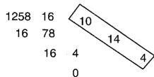
Since from the preceding table, 0 = 00H , 4 = 04H , 14 = 0EH , 10 = 0AH , the answer is 00 04 0E 0AH.
Examples of actual MIDI messages
923E5F
9n is the Note-on status, and n is the MIDI channel number. Since 2H = 2
3EH = 62, and 5FH = 95, this is a Note-on message with MIDI CH = 3.
note number 62 (note name is D4), and velocity 95.
CE 49
CnH is the Program Change status, and n is the MIDI channel number.
Since EH = 14 and 49H = 73 , this is a Program Change message with MIDI CH = 15, program number 74 (Flute in GS).
EA 00 28
EnH is the Pitch Bend Change status, and n is the MIDI channel number.
The 2nd byte (00H = 0) is the LSB and the 3rd byte (28H = 40) is the MSB, but Pitch Bend Value is a signed number in which 4000H ( = 64× 12 + 80 = 8192 ) is 0, so this Pitch Bend Value is 2800H - 4000H = 40× 12 + 80 - (64× 12 + 80) = 5120 - 8192 = -3072
If the Pitch Bend Sensitivity is set to 2 semitones, -8192 (00 00H) will cause the pitch to change -200 cents, so in this case -200 x (-3072) | (-8192) = -75 cents of Pitch Bend is being applied to MIDI channel 11.
B3 64 00 65 00 06 0C 26 00 64 7F 65 7F
BnH is the Control Change status, and n is the MIDI channel number. For Control Changes, the 2nd byte is the control number, and the 3rd byte is the value. In a case in which two or more messages consecutive messages have the same status. MIDI has a provision called "running status" which allows the status byte of the second and following messages to be omitted. Thus, the above messages have the following meaning.
B3 6400 MIDI ch.4,lower byte of RPN parameter number : 00H
(B3) 6500 (MIDI ch.4) upper byte of RPN parameter number : 00H
(B3) 060C (MIDI ch.4) upper byte of parameter value : 0CH
(B3) 2600 (MIDI ch.4) lower byte of parameter value : 00H
(B3) 647F (MIDI ch.4) lower byte of RPN parameter number : 7FH
(B3) 657F (MIDI ch.4) upper byte of RPN parameter number : 7FH
In other words, the above messages specify a value of 0C 00H for RPN parameter number 00 00H on MIDI channel 4, and then set the RPN parameter number to 7F 7FH.
RPN parameter number 00 00H is Pitch Bend Sensitivity, and the MSB of the value indicates semitone units, so a value of OCH = 12 sets the maximum pitch bend range to ±12 semitones (1 octave). (On GS sound sources the LSB of Pitch Bend Sensitivity is ignored, but the LSB should be transmitted anyway (with a value of 0) so that operation will be correct on any device.)
Once the parameter number has been specified for RPN or NRPN, all Data Entry messages transmitted on that same channel will be valid, so after the desired value has been transmitted, it is a good idea to set the parameter number to 7F 7FH to prevent accidents. This is the reason for the (B3) 64 7F (B3) 65 7F at the end.
It is not desirable for performance data (such as Standard MIDI File data) to contain many events with running status as given in . This is because if playback is halted during the song and then rewound or fast-forwarded, the sequencer may not be able to transmit the correct status, and the sound source will then misinterpret the data. Take care to give each event its own status.
It is also necessary that the RPN or NRPN parameter number setting and the value setting be done in the proper order. On some sequencers, events occurring in the same (or consecutive) clock may be transmitted in an order different than the order in which they were received. For this reason it is a good idea to slightly skew the time of each event (about 1 tick for TPQN = 96, and about 5 ticks for TPQN = 480).
*TPQN: Ticks Per Quarter Note
- Example of an Exclusive message and calculating a Checksum
Roland Exclusive messages (RQ1, DT1) are transmitted with a checksum at the end (before F7) to make sure that the message was correctly received. The value of the checksum is determined by the address and data (or size) of the transmitted exclusive message.
How to calculate the checksum (hexadecimal numbers are indicated by 'H')
The checksum is a value derived by adding the address, size and checksum itself and inverting the lower 7 bits.
Here's an example of how the checksum is calculated. We will assume that in the exclusive message we are transmitting, the address is aa bb ccH and the data or size is dd ee ffH.
aa+bb+cc+dd+ee+ff = sum
sum]128=quotient...remagain
128 - remainder = checksum
Setting REVERB MACRO to ROOM 3
According to the "Parameter Address Map," the REVERB MACRO Address is 40 01 30H, and ROOM 3 is a value of 02H. Thus,
| F0
(1) | 41
(2) | 10
(3) | 42
(4) | 12
(5) | 40 01 30
address | 02
data | ??
checksum | F7
(6) |
(1) Exclusive Status,
(4) Model ID (GS), (5) Command ID (DT1).
(3) Device ID (17),
(6) End of Exclusive
Next we calculate the checksum.
40H + 01H + 30H + 02H = 64 + 1 + 48 + 2 = 115 (sum)
115 (sum) | 128 = 0 (quotient) ... 115 (remainder)
[ \text{checksum} = 128 - 115 \text{(remainder)} = 13 = 0DH ]
This means that F0 41 10 42 12 40 01 30 02 0D F7 is the message we transmit.
Requesting transmission of the LEVEL for DRUM MAP 1 NOTE NUMBER 75 (D#5; Claves)
NOTE NUMBER 75 (D#5) is 4BH in hexadecimal.
According to the "Parameter Address Map," LEVEL of NOTE NUMBER 75 (D#5; Claves) in DRUM MAP 1 has an Address of 41 02 4BH and a Size of 00 00 01H. Thus,
| F0
(1) | 41
(2) | 10
(3) | 42
(4) | 11
(5) | 41.02.4B | 00.00.01 | ?? | E7
(6) |
(1) Exclusive Status.
(4) Model ID (GS),
(2) ID (Roland),
(5) Command ID(RQ1),
(3) Device ID (17),
(6) End of Exclusive
Next we calculate the checksum.
41H+02H+4BH+00H+00H+01H=65+2+75+0+0+1=143(sum)
143 (sum) 128 = 1 (quotient)... 15 (remainder)
[ \text{checksum} = 128 - 15 \text{(remainder)} = 113 = 71H ]
This means that F0 41 10 42 11 41 02 4B 00 00 01 71 F7 is the message we transmit.
- About tuning
In MIDI, individual Parts are tuned by sending RPN #1 (Master Fine Tuning) to the appropriate MIDI channel.
In MIDI, an entire device is tuned by either sending RPN #1 to all MIDI channels being used, or by sending a System Exclusive MASTER TUNE (address 40 00 00H).
RPN #1 allows tuning to be specified in steps of approximately 0.012 cents (to be precise, 100/8192 cent), and System Exclusive MASTER TUNE allows tuning in steps of 0.1 cent. One cent is 1/100th of a semitone.
The values of RPN #1 (Master Fine Tuning) and System Exclusive MASTER TUNE are added together to determine the actual pitch sounded by each Part.
Frequently used tuning values are given in the following table for your reference. Values are in hexadecimal (decimal in parentheses).
| Hz at A4 | cent | RPN #1 | Sys.Ex. 40 00 00 | |
| 445.0 | +19.56 | 4C 43 (+1603) | 00 04 0C 04 (+196) | |
| 444.0 | +15.67 | 4A 03 (+1283) | 00 04 09 0D (+157) | |
| 443.0 | +11.76 | 47 44 (+ 964) | 00 04 07 06 (+118) | |
| 442.0 | + 7.85 | 45 03 (+ 643) | 00 04 04 0F (+ 79) | |
| 441.0 | + 3.93 | 42 42 (+ 322) | 00 04 02 07 (+ 39) | |
| 440.0 | 0 | 40 00 (0) | 00 04 00 00 (0) | |
| 439.0 | - 3.94 | 3D 3D (- 323) | 00 03 0D 09 (- 39) | |
| 438.0 | - 7.89 | 3A 7A (- 646) | 00 03 0B 01 (- 79) | |
Set the tuning of MiDI channel 3 to A4 = 442.0Hz
Send RPN#1 to MIDI channel 3. From the above table, the value is 4503H.
B2 6400 MIDl ch.3,lower byte of RPN parameter number :00H
(B2) 6501 (MIDI ch.3) upper byte of RPN parameter number : 01H
(B2) 0645 (MIDI ch.3) upper byte of parameter value : 45H
(B2) 2603 (MIDI ch.3) lower byte of parameter value : 03H
(B2) 647F (MIDI ch.3) lower byte of RPN parameter number : 7FH
(B2) 657F (MIDI ch.3) upper byte of RPN parameter number : 7FH
The Scale Tune Feature (address: 401x40)
The scale Tune feature allows you to finely adjust the individual pitch of the notes from C through B. Though the settings are made while working with one octave, the fine adjustments will affect all octaves. By making the appropriate Scale Tune settings, you can obtain a complete variety of tuning methods other than equal temperament. As examples, three possible types of scale setting are explained below.
Equal Temperament
This method of tuning divides the octave into 12 equal parts. It is currently the most widely used form of tuning.
especially in occidental music. On this unit, the default settings for the Scale Tune feature produce equal temperament.
Just Temperament (Keytone C)
The three main chords resound much more beautifully than with equal temperament, but this benefit can only be obtained in one key. If transposed, the chords tend to become ambiguous. The example given involves settings for a key in which C is the keynote.
O Arabian Scale
By altering the setting for Scale Tune, you can obtain a variety of other tunings suited for ethnic music. For example, the settings introduced below will set the unit to use the Arabian Scale.
Example Settings
| Note name | Equal Temperament | Just Temperament (Keytone C) | Arabian Scale |
| C | 0 | 0 | -6 |
| C# | 0 | -8 | +45 |
| D | 0 | +4 | -2 |
| D# | 0 | +16 | -12 |
| E | 0 | -14 | -51 |
| F | 0 | -2 | -8 |
| F# | 0 | -10 | +43 |
| G | 0 | +2 | -4 |
| G# | 0 | +14 | +47 |
| A | 0 | -16 | 0 |
| A# | 0 | +14 | -10 |
| B | 0 | -12 | -49 |
The values in the table are given in cents. Refer to the explanation of Scale Tuning on page 9 to convert these values to hexadecimal, and transmit them as exclusive data. For example, to set the tune (C-B) of the Part1 Arabian Scale, send the data as follows:
F0411042124011403A6D3E340D386B3C6F4036OF76F7
| Function | Transmitted | Recognized | Remarks |
| Basic Channel | Default | 1-2-3-4-5-7-8-9-10-11-16 | 1-14, 16 | 1=Acc12=Acc Bass9=Acc63=Acc210=Acc Drums/Sll4=UpperPC5=Acc311=Sampler6=RX112=RX27=Acc413=RX38=Acc514=Note to Arr. |
| Changed | × | × |
| Mode | Default | Mode 3 | Mode 3 | *2 |
| Message | Mode 3, 4(M=1) | Mode 3, 4(M=1) |
| Altered | ***** | |
| Note Number | True Voice | 0-127**** | 0-1270-127 | |
| Velocity | Note ON | ○ *1 | ○ | |
| Note OFF | × | × | |
| After Touch | Key's | × | ○ | |
| Ch's | × | ○ | |
| Pitch Bend | ○ | ○ | |
| Control Change | 0, 32 | ○ | ○ | Bank SelectModulationPortamento TimeData EntryVolumePanpotExpressionHold 1PortamentoSostenutoSoftPortamento ControlEffect 1 DepthEffect 3 DepthNRPN LSB,MSBRPN LSB,MSB |
| 1 | ○ | ○ |
| 5 | ○ | ○ |
| 6, 38 | ○ | ○ |
| 7 | × | ○ |
| 10 | ○ | ○ |
| 11 | ○ | ○ |
| 64 | ○ | ○ |
| 65 | ○ | ○ |
| 66 | × | ○ |
| 67 | × | ○ |
| 84 | × | ○ |
| 91 | ○ | ○ (Reverb) |
| 93 | ○ | ○ (Chorus) |
| 98, 99 | ○ | ○ |
| 100,101 | ○ | ○ |
| Program Change | True # | ○***** | ○0-127 | Program Number: 1-128 |
| System Exclusive | ○ | ○ | |
| System Common | Song Pos | × | × | |
| Song Sel | × | × |
| Tune | × | × |
| System Real Time | Clock | ○ | ○ | F8FA, FC |
| Commands | ○ | ○ |
| Aux Messages | All Sounds OffReset All ControllersLocal On/OffAll Notes OffActive SenseReset | ×××××× | ○ (120,126,127)○ (121)○ (122)○ (123-125)○× | |
| Notes | *1 ○ × is selectable.*2 Recognize as M=1 even if M≠1 |
Mode 1: OMNI ON, POLY
Mode 3 : OMNI OFF, POLY
Mode 2 : OMNI ON, MONO
Mode 4: OMNI OFF, MONO
O:Yes
X:No