
2304 - Tableau d'affichage Quartet - Notice d'utilisation et mode d'emploi gratuit
Retrouvez gratuitement la notice de l'appareil 2304 Quartet au format PDF.


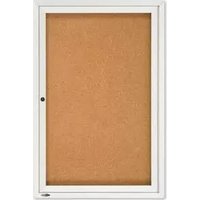
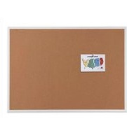
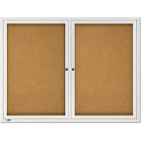
| Type de produit | Tableau d'affichage mural ou sur pied |
| Marque | Quartet |
| Modèle | 2304 |
| Dimensions (L x H x P) | 60 x 90 x 2 cm |
| Poids | Environ 2,5 kg |
| Matériau de surface | Liège ou feutre synthétique |
| Cadre | Aluminium anodisé argenté |
| Alimentation | Aucune (utilisation manuelle) |
| Fonction principale | Affichage de documents, notes, photos à l'aide de punaises ou d'aimants |
| Système de fixation | Crochets muraux inclus ou chevilles pour fixation murale |
| Accessoires fournis | Kit de fixation murale, poignée (selon modèle) |
| Entretien et nettoyage | Dépoussiérer avec un chiffon sec ou légèrement humide. Ne pas utiliser de produits abrasifs. |
| Sécurité | Bords arrondis pour éviter les blessures. Utiliser des punaises adaptées. |
| Pièces détachées et réparabilité | Pièces non disponibles séparément. En cas de dommage, remplacer l'ensemble. |
| Utilisation recommandée | Bureau, salle de réunion, école, maison |
| Couleur du cadre | Argent |
| Orientation | Verticale ou horizontale selon fixation |
FOIRE AUX QUESTIONS - 2304 Quartet
Astuce : Vérifiez le niveau à l'aide d'un niveau à bulle.
Pièces de rechange : Non disponibles individuellement ; contactez le service client pour un remplacement sous garantie.
Questions des utilisateurs sur 2304 Quartet
0 question sur cet appareil. Repondez a celles que vous connaissez ou posez la votre.
Poser une nouvelle question sur cet appareil
Téléchargez la notice de votre Tableau d'affichage au format PDF gratuitement ! Retrouvez votre notice 2304 - Quartet et reprennez votre appareil électronique en main. Sur cette page sont publiés tous les documents nécessaires à l'utilisation de votre appareil 2304 de la marque Quartet.
MODE D'EMPLOI 2304 Quartet
EURO ALUMINUM FRAME BOARD – Mounting Instructions
*NOTE – For Dry-Erase Boards:
Before mounting board to wall, please refer to instructions in "Accessory Kit" to attach the marker tray to the board frame.
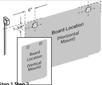


Step 1 Step 2
Determine board location. To position top hanging brackets, mark center hole of hanger 6" from outside edge of board and 1-3/8" down from top of board (A). Drill holes for each hanger in marked locations using a 1/4" drill bit. Tap anchor into hole flush to wall with metal "teeth" firmly embedded. Turn screw clockwise to expand metal legs. Stop when strong resistance is felt and legs are fully expanded.
Turn screw counter-clockwise to remove screw from anchor and re-insert through hanging bracket into wall anchor (B). Tighten firmly. Holding the board at (approx.) 15° angle, place the channel in the back of the frame over the wall hangers. Lower the board so it is flush to the wall (C).

Remove plastic corner caps (D), mark wall through top hole of each corner (E). Remove board from wall and drill holes in marked locations using a 1/4" drill bit. Install wall anchors as indicated in Step #1 (F). Re-hang board and insert screw through plastic corner and into wall anchor. Tighten firmly. Replace corner caps by pressing into place over the screws. (L-Brackets & Truss Head Screws are not required.)
ALUMINUM FRAME BOARD – Mounting Instructions
*NOTE – For Dry-Erase Boards:
Before mounting board to wall, please refer to instructions in "Accessory Kit" to attach the marker tray to the board frame.


Step 1
Determine board location. To position top hanging brackets, mark center hole of hanger 6" from outside edge of board and 7/8" down from top of board (A). Drill holes for each hanger in marked locations using a 1/4" drill bit. Tap anchor into hole flush to wall with metal "teeth" firmly embedded. Turn screw clockwise to expand metal legs. Stop when strong resistance is felt and legs are fully expanded.
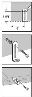
Turn screw counter-clockwise to remove screw from anchor and re-insert through hanging bracket into wall anchor (B). Tighten firmly. Holding the board at (approx.) 15° angle, place the channel in the back of the frame over the wall hangers. Lower the board so it is flush to the wall (C).
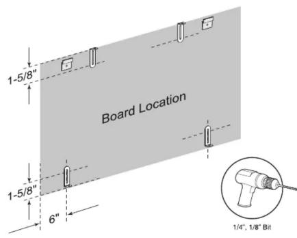
Step 2
To position bottom "L" brackets, mark wall 1-5/8" up from bottom of board 6" from each outside edge (D). To position top "L" brackets, mark wall 1-5/8" down from top of board and a 1/4 of the board width from each outside edge. Drill holes in marked locations using a 1/4" drill bit. Insert wall anchors and mount "L" brackets as indicated in Step #1 (E). Hang board and mark frame through hole in each "L" bracket. Remove board and drill pilot hole at each mark with 1/8" drill bit. Re-hang board and insert #8 x 1/2" truss head screw through each "L" bracket and into pilot hole in frame (F). Tighten firmly.
WOOD FINISH FRAME BOARD – Mounting Instructions
*NOTE – For Dry-Erase Boards:
Before mounting board to wall, please refer to instructions in "Accessory Kit" to attach the marker tray to the board frame.


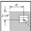


Step 1
Determine board location. To position top hanging brackets, mark center hole of hanger 6" from outside edge of board and 2-1/4" down from top of board (A). Drill holes for each hanger in marked locations using a 1/4" drill bit. Tap anchor into hole flush to wall with metal "teeth" firmly embedded. Turn screw clockwise to expand metal legs. Stop when strong resistance is felt and legs are fully expanded.
Insert screws through hanging brackets into the wall anchor (B). Tighten firmly. Place the channel in the back of the frame over the wall hangers. Push top of frame down until board is fully engaged on hangers (C).


Step 2
To position bottom "L" brackets, mark wall 2-1/2" up from bottom of board 6" from each outside edge (D). To position top "L" brackets, mark wall 2" down from top of board and a 1/4 of the board width from each outside edge. Drill holes in marked locations using a 1/4" drill bit. Insert wall anchors and mount "L" brackets as indicated in Step #1 (E). Hang board and mark frame through hole in each "L" bracket. Remove board and drill pilot hole at each mark with 1/8" drill bit. Re-hang board and insert #8 x 1/2" truss head screw through each "L" bracket and into pilot hole in frame (F). Tighten firmly.
ACCESSORY PAGE CLIP
- Applies to all boards

Hardware Kit


Dry-Erase and Bulletin Board
Installation Instructions

natural_image
Illustration of a flat-screen monitor with a mesh pattern on the screen and a magnified inset showing a circular detail (no text or symbols)
ACCO Brands
300 Tower Parkway
Lincolnshire, IL 60069-3640
www.quartet.com
www.acco.com


Marque : Quartet
Modèle : 2304
Catégorie : Tableau d'affichage