
900 (1992) - Voiture SAAB - Notice d'utilisation et mode d'emploi gratuit
Retrouvez gratuitement la notice de l'appareil 900 (1992) SAAB au format PDF.


| Type de produit | Voiture |
| Marque | Saab |
| Modèle | 900 |
| Année | 1992 |
| Catégorie | Berline |
| Type de carrosserie | Berline 3/5 portes |
| Motorisation | Essence 2.0L ou 2.3L |
| Transmission | Manuelle 5 vitesses ou automatique 4 vitesses |
| Longueur | 468 cm |
| Largeur | 169 cm |
| Hauteur | 143 cm |
| Empattement | 252 cm |
| Poids à vide | Environ 1300 kg |
| Capacité du réservoir | 68 L |
| Type de carburant | Essence sans plomb |
| Puissance | 130 à 185 ch |
| Couple | 172 à 260 Nm |
| Vitesse maximale | 190 à 220 km/h |
| Consommation mixte | 8 à 12 L/100km |
| Freins avant/arrière | Disques ventilés / Disques |
| Pneus | 185/65 R15 ou 195/60 R15 |
| Capacité du coffre | 410 L |
| Nombre de places | 5 |
| Direction | Assistée |
| Suspension avant/arrière | McPherson / Essieu rigide |
FOIRE AUX QUESTIONS - 900 (1992) SAAB
Questions des utilisateurs sur 900 (1992) SAAB
0 question sur cet appareil. Repondez a celles que vous connaissez ou posez la votre.
Poser une nouvelle question sur cet appareil
Téléchargez la notice de votre Voiture au format PDF gratuitement ! Retrouvez votre notice 900 (1992) - SAAB et reprennez votre appareil électronique en main. Sur cette page sont publiés tous les documents nécessaires à l'utilisation de votre appareil 900 (1992) de la marque SAAB.
MODE D'EMPLOI 900 (1992) SAAB
Saab 900
natural_image
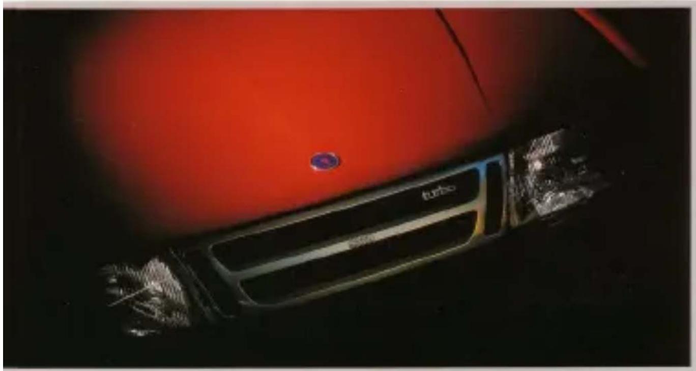
Close-up of a red car's front grille with visible brand logo and 'turbo' branding (no readable text beyond logo)Owner's Manual M 1992

SAAB

Owner's Manual
Saab 900 M 1992
Instruments and controls 3
Interior equipment 13
Doors, locks and luggage compartment 29
Starting and driving 35
Car care and maintenance 47
Technical data 69
Index 80
Seab Automobile AB 1991
Technical Publications, Sab Automobile AB Trollhazzan, Sweden Printed by: Vazargastands Tryleri AB, Skars

natural_image
Side view of a silver sedan car parked on a coastal road with ocean background (no visible text or symbols)This manual for the Saab 900 provides some practical advice on driving and caring for your car. The manual also describes the most important differences between model versions. When mentioned in the manual, 900i 16 = 16-valve engine naturally aspirated and 900 Turbo 15 = 16-valve engine with turbo charger.
Read through the manual before taking the car cut for the first time and then keep it in the car for future reference.
The manual is divided into a number of sections and there is also a comprehensive index at the back.
Supplied with the car are a Service Book and important information about warranty conditions.
Since the policy at Saab Automobile is one of continual improvement, we retain the right to incorporate modifications and alter specifications during production without prior notice.
Best wishes.
Saab Automobile A8
The scale shown in some of the photogrids in this loaded to not included as standard equipment for the car.

Instruments and controls
Instrument panel 4
Indicator and warning lights . . . 4
Instruments 5
Switches 6
Heating and ventilation system. 10
Instrument panel

Cars with anti-lock braking system

Main instrument display panel
1 Rev counter and clock
2 Indicator/warming lights
3 Direction indicator repeater light
4 Speedometer kilometer and trip meter
5 Pressure gauge
6. Temperature gauge
7 Fuel gauge
8 Dimmer switch, instrument illumination
9 Trip meter reset knob
10 Clock reset knob
Indicator and warning lights
Some of the warning lights came on as the ignition is switched on. These lights should all be extinguished as soon as the engine has been started.

Fuel injection system warning light
This light indicates a malfunction in the fuel injection system. Although an emergency system in the electronic control unit will take over, enabling you to continue your journey with somewhat diminished engine performance, the car should be taken to your Saab dealer as soon as possible.

Indicator light for rear-window heating
This light will show when the rear-window heating is switched on.

Oil pressure warning light
This light will come on if the engine oil pressure should fall too low. If the light flashes or comes on while you are driving, stop the car immediately, switch off the engine and check the oil level.
The car must not be driven while this light is on.

Charging warning light
This light will come on if the battery is not being charged. If it comes on while you are driving, stop the car immediately and switch off the engine. Check the alternator drive belt: if it is slack or broken, not only will the battery not be charged but cooling of the engine will also be inadequate.

Main beam indicator light
This light will show when the main beam is on.
Rear fog lamp indicator light
This light will show when the rear fog lights are switched on.

Handbrake warning light
This light will show when the handbrake is applied.

ABS warning light (option)
This light indicates that the ABS system is inoperative. Conventional braking is still available but have the ABS system checked by an authorized Saab dealer without delay.

Brake warning light
The brake warning light will come on if the brake fluid level falls too low. If the light comes on while you are driving, stop the car immediately and check the level of brake fluid in the reservoir. On cars with ABS brakes, the light will also come on in combination with the ANTI LOCK warning light if there is a drop in pressure in the brake servo system. In such a case the servo pressure will be used up after braking a few times and power assistance will be lost.
WARNING
If power assistance is lost, braking effect is greatly reduced, together with a big increase in required pressure on the brake pedal, and the car should only be driven if absolutely necessary.
Have the car checked and corrected immediately by an authorized Saab dealer.
Fuel gauge (FUEL)

Fuel warning light
This light will show when less than about 7 litres (1.5 imp. gal) of fuel remains in the tank 16 valve engine: If the fuel tank has run dry at least 5 litres of fuel (just over a gallon) will have to be added for the engine to be started when the car is standing on level ground. If the car is on a slope, as much as 13 litres (approx. 3 gallons) may have to be added.
Instruments
Clock
In all models the clock is incorporated in the rev counter.
Rev counter
The rev counter shows the engine speed in thousands of revs per minute. For maximum fuel economy, the needle should be kept within the green zone. The needle may briefly enter the broken red zone but must never be allowed to enter the solid red zone.
Saab 900 Turbo 16 only: A safety cut-out function prevents the engine speed exceeding approximately 6,000 rimin.
Speedometer, millimeter and trip meter
The kilometer records the distance traveled in miles or kilometres and the trip meter in miles/kilometres and tenths.
Temperature gauge
The temperature gauge indicates the temperature of the coolant. When the needle has just entered the green zone, it indicates a temperature of 50°C (122°F), which is the beginning of the normal temperature range for the engine. With the needle in this position, the engine may be driven at full load (full throttle) for short periods. Saab 900 Turbo-16 modes must not be driven at full throttle before the needle is well inside the green zone.
If the temperature indicator approaches the red section (this may occur when the ambient temperature is extremely high or at very high engine loads), the highest possible gear should be selected to reduce the engine speed as much as possible. Avoid changing down. If the pointer should move into the red section in spite of those measures, stop the car and let the engine idle. If the indicator moves into the red section repeatedly, stop as soon as possible and check the coolant level.
Pressure gauge (900 Turbo 16)
The pressure gauge indicates the pressure in the inlet manifold. When the engine is only lightly loaded and during engine overrun (engine braking) a depression will be present in the inlet manifold and the needle on the gauge will be within the white zone. At higher engine speeds and when the engine is under a greater load, the turbocharger will boost the pressure in the inlet manifold and the needle will enter the yellow zone.
Under normal conditions, the needle should not enter the red zone as a safety cut-out system will limit the charging pressure to protect the engine. However, under certain atmospheric conditions, the needle may just enter the red zone, which does not mean that the system is malfunctioning in any way. But if the needle repeatedly enters the red zone and a loss in engine power is also experienced (because the safety cut-out system is limiting the charging pressure), the car should be taken to an authorized Seab dealer without delay.
Switches
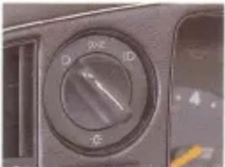
Headlights and parking lights

The lighting is off.
Note!
Please note instrument illumination is lit at all times when the ignition is on.

Parking lights
The parking lights can be switched on irrespective of the position of the ignition key. Parking lights should only be used when the car is stationary.

Headlights
The headlights can be switched on when the ignition switch is in the drive or parking position.
N.B. The headlights will be extinguished automatically when the ignition switch is turned to the locking position (L). This does not apply to the parking lights, which can still be used with the ignition switch in this position.

Main/dipped beam
To change from main beam to dipped beam or vice versa, lift the stalk towards the steering wheel. This will also flash the headlights on main beam if the headlights are not switched on.
natural_image
Close-up of a car's air conditioner dial showing D, 20°C, and ID buttons (no text or symbols beyond labels)Switch for parking lights and head- lights 90 mo
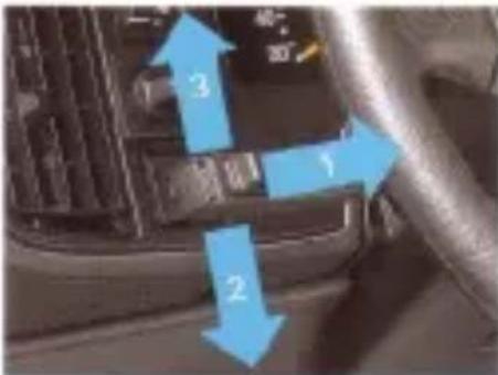
Steak switch for main/dipped beam and direction indicators
1 Main/dipped beam or headlight flasher
2. Indicators for left turn
3 Indicators for right turn
SIGOOGA
Headlight beam-length adjustment
Some variants are equipped with a system for adjusting the length of the beam from the headlights when this is affected by the way in which the car is loaded. The system comprises an actuator motor at either headlight and a switch on the lascia. The switch, which must not be operated unless the ignition is on, has the following four positions:
0- Frontseat passenger and/or driver only (no luggage)
1- Driver plus 4 passengers only (no luggage)
2- Fully laden (Driver plus 4 passengers and max. load in boot or driver only plus max. load in boot)
3- Maximum trailer load (Driver only plus maximum trailer load)
Note
The above is intended as a guide to suitable switch positions. This facility is provided to enable the driver to use his own discretion to choose the setting that will give optimum lighting on dipped beam without dazzling other road users.

Direction indicators
To switch on the direction indicators, move the stalk up or down. The stalk has a spring-loaded position for use of the indicators for changing lenses or overtaking. In the fixed position, the indicators will remain on until

natural_image
Close-up of a camera control panel with a blue arrow pointing to the left side (no visible text or symbols)Switch for adjustment of headlight beam-length
cancelled automatically by the steering wheel.
The respective repeater light on the instrument panel will flash at the same rate as the direction indicators.
Reversing lights
The reversing lights come on automatically when reverse gear is selected.
Instrument illumination
The brightness of the instrument illumination can be varied by means of the dimmer switch. (Rheostat.)
Interior lighting
There are three interior lights: a dome light on the ceiling, a light on the rear-view mirror and a light by the ignition switch (Combi Coupé and Sedan). Sasso 900 Convertible have four interior lights; one on the rearview mirror, one by the ignition switch and two courtesy lights for rear-seat passengers. The lights are operated by a three-position switch on the console between the front seats.
Switch position 2: Lighting on continuously Switch position 0: Lighting off
Switch position 1: Lighting comes on when a door is opened
in some models, the lights will switch off automatically either after a delay of about
Switch for interior lights

natural_image
Close-up of a car gear shift lever with a blue arrow pointing to the pivot point (no text or symbols visible)50.479
natural_image
Top-down view of a rectangular electronic component with grid pattern and two gold contacts (no visible text or symbols)Luggage compartment light 50 664
fifteen seconds after the last door has been closed or when the ignition switch is moved to the drive position.
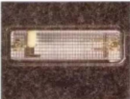
Luggage compartment light
The luggage compartment light is switched on/istinguished automatically when the luggage compartment door is opened- enclosed. The light can also be switched off by moving the switch to the middle position.

Rear log light (certain markets)
The rear fog light is incorporated in the rear left or right light cluster (depending on left-or-right-hand traffic) and is switched on by
means of a switch on the instrument panel. The rear fog light operates only when the headlights are on. A light on the instrument display panel will show when the rear fog light is switched on. Make sure that you are familiar with the law regarding the use of rear fog lights.

Hazard warning lights
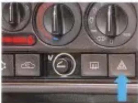
When this switch is depressed, all four direction indicator lights will flash simultaneously. An indicator light in the switch and both direction indicator repeater lights on the instrument panel will also flash. The hazard warning lights should only be used if, because of a collision or breakdown, the car constitutes a danger or obstruction to other road users.
Hazard warning light switch
natural_image
Close-up of a car air conditioning control panel with buttons and gauges (no readable text or symbols)83 967
Stalk switch for wipers and washers
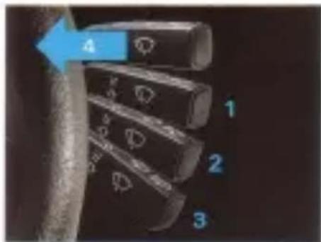
The stalk switch for the wipers and washers has the following positions:
1 Windscreen wipers, intermittent operation. The wipers will make a double sweep every few seconds. This function is particularly useful in light rain or drizzle.
2 Windscreen wipers. low speed.
3. Windscreen wipers, high speed.
4 Lifting the stalk switch towards the steering wheel will operate the washers and wipers for the headlights and windscreen.
Stalk switch for wipers and washers
305 878

Switch for near-window heating 80 mm

Heated rear window
The switch for heating of the rear window is located on the dashboard. A warning light on the instrument display panel will show when the heating is switched on.
Switch the heating off as soon as the rear window is free from ice or mist. Refrain from placing sharp or hard objects on the rear parcel shelf, to avoid damaging the heater elements.
Do not switch on the rear window heating before the engine is running.
Cars for some markets are equipped with a time-delay relay which limits to a few minutes the time during which the rear window is electrically heated.

Switch for the electrically heated 90 kV driver's seat

Heated driving seat
On some variants the driving seat is equipped with adjustable heating of the seat cushion and backrest. The control on the dashboard has three heating settings, with position 3 providing maximum heat. With the control in position 0, the heating is switched off altogether.
Heating and ventilation system
Fresh air is drawn in through an inlet in the bonnet. An efficient filter removes dust and other particles from the air before it flows through the heating and ventilation system into the car. On the Combi Coupe air is evacuated from the car through an outlet on either side at the rear of the car. On Sedan and Convertible models, the air evacuation outlet is located underneath the rear bumper.
Heating and ventilation controls
- Fair switch
2 Temperature control
3 Air distribution control

李国栋

Fan
The amount of air admitted to the car is controlled by the fan switch. The fan runs continuously except when the air distribution control is set to 0.
To increase the airflow, turn the fan control clockwise.
Temperature control
Infinitely variable control of the temperature of the supply air (between the limits) is pos-
Air vents
1 Defrostervents
2 Side vents
3. Central panel vents
4 Floor vents

sible by means of the temperature control. Turn the control clockwise to increase the temperature.
BOSTR
Air distribution control
The air distribution control is used to direct the supply of air to the defroster, panel and floor vents.
Joysticks on the panel vents enable the direction of the air flow to be selected as desired (for instance, in very cold weather it may be advisable to direct the air flow onto the side windows to enhance the defrosting effect). The thumb wheels on the panel vents enable the amount of air admitted to be adjusted for each vent individually. Note that the top section of the side vents is permanently open.
Recommended control settings
Cold weather. For rapid defrosting, turn the air distribution control to position and select the maximum fan speed.
Thereafter, to keep the inside of the car at a comfortable temperature, turn the air distribution control to position or and select a suitable fan speed and temperature.
Hot weather. When the car is very hot and maximum cooling is required, turn the air distribution control to position ◇ and select the maximum fan speed.
Thereafter, to maintain comfortable ventilation, turn the control to position <> or and select a suitable fan speed. For an adequate air change rate inside the car, the fan should be used even when the car is travelling at speed. Regulate the temperature of the incoming air as required.
Note that the central panel vents admit only unheated fresh air.
Misted windows
For rapid demisting turn the air distribution control to position 📋 and select fan speed 2 or 3 at highspeed driving.
Switches for the air conditioning system
↑ Devall
2 Air recirculation

SIG 8018
Air conditioning (when fitted)
When fitted, the air conditioning system is incorporated in the standard heating and ventilation system and operated by the same controls. To switch on the air conditioning, depress the AC switch on the instrument panel.
N.B. Starting of the air conditioner compressor is delayed by about 10 seconds when the engine is started, in order to avoid applying additional load onto the engine. This delay will be operative only if the AC switch has been pressed before the ignition has been switched on.
For rapid cooling of the air inside the car in hot weather or to avoid exhaust fumes being drawn into the car in traffic jams, press the air recirculation switch, whereupon the fresh air intake will be closed and the air inside the car recirculated through the ventilation system. To reduce the likelihood of the windows misting up inside the car, the air recirculation function will only operate when the AC system is switched on. N.B. Do not use the air recirculation facility in cold weather as this can result in ice and mist forming on the windows.
When the air distribution control is set to 0 or ◇, the system will override the air recirculation setting, i.e. the flash air intake will be closed regardless of whether the AC and air recirculation switches are on or off. N.B. If the engine is running hot, there is no need to switch off the AC system as a thermostat in the system will switch off the AC compressor automatically if necessary. If the air conditioning system is not working properly, refer to the section 'Air conditioning - fault diagnosis'.
Climate system tips
Defogging windows - Switching on the AC compressor in combination with turning up the temperature control will accelerate de- logging. The recirculation switch should be off.
Defroating windshield - For maximum effect, turn the temperature control fully clockwise and the air distribution control to twelve o'clock. Increases the fan speed as the air begins to warm up.
Heat plus fresh air - On a long winter drive, cool air directed toward the face can help light drowsiness. Select the nine o'clock position on the air distribution control and adjust the corner panel vent to suit.
AC modulation - For maximum cooldown, engage the AC switch and select the seven o'clock position on the air distribution control (temperature control fully counter clockwise to blue spot). As the desired comfort level is reached, switch the air distribution to eight o'clock and adjust fan speed to suit. To maintain comfort on moderate days, add heat to the outer vents by turning up the temperature control part way. Direct the fully cold air from the corner vent toward the rear, between the front seats, or close it with the thumb wheel switch on the vent itself.
Instruments and controls

natural_image
Interior view of a car dashboard with red arrows indicating airflow or traffic direction (no text or symbols)
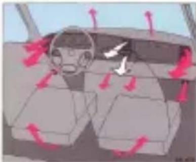
Deltroster vents open.

natural_image
Interior view of a car showing airflow direction arrows and dashboard (no text or symbols)
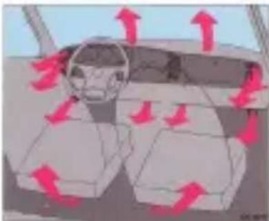
Maximum air flow for rapid cooling. All panel vents fully open. The tan runs automatically at maximum speed. Cars without AC: Floor vents partially open. Cars with AC: Floor vents closed.
natural_image
Interior view of a car showing steering wheel, dashboard, and side seats with red directional arrows indicating airflow or movement (no text or symbols)
Floor and defrostier vents open.
natural_image
Interior view of a car dashboard with red directional arrows indicating traffic flow (no text or symbols)
All panel vents fully open. Cars without AC: Floor vents partially open. Cars with AC: Normal setting. Floor vents closed.

natural_image
Interior view of a car showing steering wheel, dashboard, and rear seats with red directional arrows indicating motion (no text or symbols)
Floor vents open.

natural_image
Interior view of a car showing airflow direction arrows and dashboard controls (no text or symbols)
Floor vents and central panel vents fully open.
natural_image
Interior view of a luxury car seat with beige leather seats and black leather seats, no visible text or symbols.Interior equipment
Seats 14
Seat belts 15
Child safety 17
Rear-view mirrors 18
Ashtrays 19
Electric windows. 20
Sunroof 20
Convertible top....21
Audio equipment 27
Seats
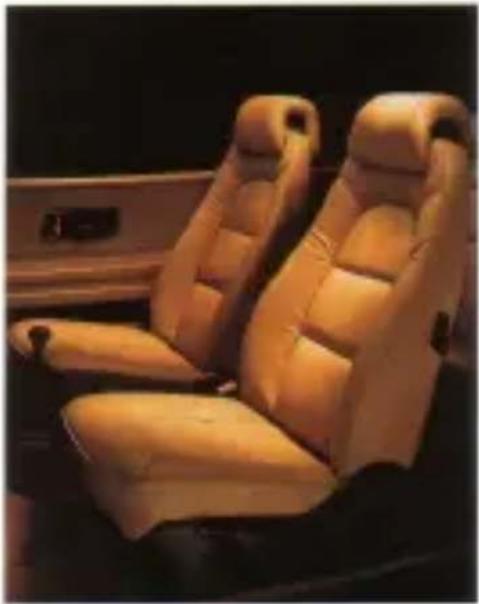
The backrest and cushion of the front seats are equipped with electric heating, which is controlled automatically by a thermostat when the ignition is on. In some models, the heating of the driver's seat is adjustable. The heating will only operate when the ignition is on and the seat is cold.
Both front seats can be adjusted for leg-room and the rake angle of the backrests has infinitely variable adjustment within the limits. The driving seat is also adjustable for height. In Convertible and three-door models, the backreats can be folded forwards.
The seats of cars for the FE- and ME-markets have no electric heating.
Head restraint
The head restraints can be raised or lowered and to give maximum protection should be adjusted to the same height as the occupant's head.
To raise the head restraint: grip it on either side and pull it straight up.
To lower the head restraint press the top straight down.
To adjust the head restraint
Pull the head restraint up or push it down until it is in the correct position. For best protection, the head restraint should be level with the occupant's head.
Legroom adjustment
Lift the bar and slide the seat to the desired position. Release the bar and check that the seat is locked in the new position.
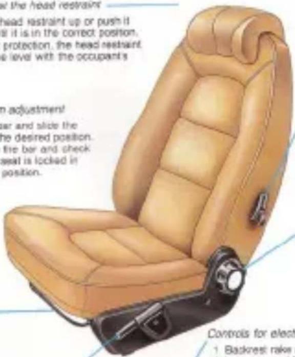
To fold the backrest forward, (3-door and Convertible)
Release the backrest by raising the lower and then fold the backrest forward.
Backrest rake angle
To adjust the backrest, turn the wheel until the backrest is in the desired position.
Height adjustment
Pull forward the telescopic lever and raise or lower the lever until the desired height is obtained.
Controls for electrically adjustable front seats
1 Backrest rake angle
2 Legroom and height adjustment

natural_image
Close-up of a car door handle with labeled parts (no text or symbols visible)Electrically adjustable seats
Some variants are equipped with electrically adjustable front seats, which are also an option on certain other variants.
The top control is for adjustment of the backrest. In addition to legroom adjustment, the lower control provides individual height adjustment of the front (thigh support) and back of the seat.
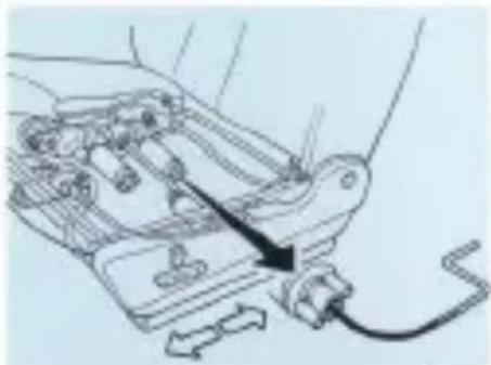
In the event of an electrical fault, a special winder included in the tool kit can be used to adjust the seat manually for legroom.
Seat belts
Always fasten your seat belt. This also applies to back-seat passengers. Research
Location of winder
natural_image
Mechanical assembly diagram showing a lever mechanism with no visible text or symbols金21118
has established that it is equally dangerous for rear-seat passengers not to wear seat belts. In the event of a collision, unrestrained rear-seat passengers are thrown violently forward against the front-seat backrests. This doubles the force put on the front-seat occupants and seat belts, frequently resulting in injury to all the occupants. Each belt may only be worn by one person at a time.
Apart from the belt for the middle rear-seat passenger (n/a Convertible), the seat belts are of the inertia reel type. To faston a seat belt, pull the strap gently out of the reel and insert the tongue in the buckle. Make sure that the tongue is properly secured.
For maximum protection, the seat belt should be worn with the hip strap low across the hips and the diagonal strap well
Taking hold of the front seat belt

natural_image
Close-up of a hand wearing a red jacket and black leather belt (no visible text or symbols)5G1120

591130
Front seat belt
1 Tongue
2. Buckie
in on the shoulder but not too close to the neck. Make sure that the belt is not twisted or rubbing against any sharp edges and that there is no unnecessary slack in the straps. To release the buckle, press the red button marked PRESS.
Expectant mothers should take care to fit the belt such that it does not apply pressure to the abdomen. The hip strap should be as low as possible across the hips.
Most of the time when the belt is being worn the reel will not be looked, thus allowing freedom of movement. However, the reel will lock if the strap is jerked or withdrawn sharply, if the car is tilted at a steep angle, or if the car brakes hard or is involved in a collision. The seat belt warning light on the instrument panel will show it either of the
front seat occupants has neglected to fasten his belt.
The belt for the middle rear-seat passenger is of the lap-belt type and can be adjusted manually. If required, lengthen the belt before fastening it by holding the adjuster at right angles to the strap and pulling the strap cut. Tighten the belt by pulling the free end until the belt fits snugly against the body. To release the belt, press the red button on the buckle.
CAUTION
Make sure that the belts do not become trapped when the rear seat is tipped forward or folded back.
Adjusting the length of the lap belt

natural_image
Close-up of hands adjusting a dark fabric or zipper, wearing a red blazer with a gold emblem (no visible text or symbols)831128
WARNING:
- Seat belts are designed to bear upon the bony structure of the body, and should be worn low across the front of the pelvis, or the pelvis, chest and shoulders, as applicable: wearing the lap section of the belt across the abdominal area must be avoided.
- Seat belts should be adjusted as firmly as possible, consistent with comfort, to provide the protection for which they have been designed. A slack belt will greatly reduce the protection afforded to the wearer.
- Care should be taken to avoid contamination of the webbing with polishes, oils and chemicals, and particularly battery acid. Cleaning may safely be carried out using mild soap and water. The belt
Correct position of the seat belt

natural_image
Illustration of a robotic arm with a steering wheel and mechanical components (no text or symbols visible)30 319
should be replaced if webbing becomes traved, contaminated or damaged.
- It is essential to replace the entire assembly after it has been worn in a severe impact even if damage to the assembly is not obvious.
- Belts should not be worn with straps twisted.
- Each belt assembly must only be used by one occupant; it is dangerous to put a belt around a child being carried on the occupant's lap.
- No modifications or additions should be made by the user which either prevent the seat belt adjusting devices from operating to remove slack, or prevent the seat belt assembly from being adjusted to remove slack.

natural_image
Child sitting in a pink car seat, holding a book (no visible text or symbols)03 766
Child safety
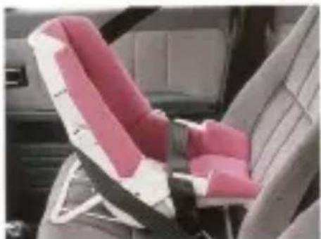
To travel safely in the car, children must be restrained in some way. However, the restraint used must be suitable for the size of the child. For this reason, before fitting any type of safety seat or harness, consult your Saab dealer, who will be pleased to advise you on the most suitable type of restraint.
When a child is able to sit up by itself, a properly fitted child seat provides the best protection. However, these should no longer be used when a child has outgrown them, i.e. when they no longer provide ample support for the head and legs.
When a child has outgrown child seats, the standard seat belt with a booster cushion should be used. Make sure that you are familiar with the law regarding child passengers.

natural_image
Line drawing of a car showing the open trunk and side rear window, with no text or symbols present.Child nutrient anchorages, 800
SG138
Combi Couple and Sedan
natural_image
Interior view of a car seat with pink and white leather seats (no visible text or symbols)5G 786
Child restraint anchorages, 900 Combi Coupé and Sedan (Australia only)
To attach the restraints:
1 Remove the covering plugs from the holes under the two cross-shaped cuts in the luggage compartment floor carpet.
2 Fasion the anchor bolts with their shackles in the holes, using specialty designed spacers.
3. Bolt dimension: UNC 5/16, length 25 mm. Spacer dimension: 20 mm e (hole 12 mm e), thickness 10 mm.

natural_image
Pure technical line drawing of a mechanical assembly without any text, numbers, or symbolsChild restraint anchorages, 900 Convertible
SG1018
Child restraint anchorages, 900 Convertible (Australia only)
To attach the restraints:
1 Raise the convertible top and lower the rear screen.
2 Operating from outside of the car, locate the zippers situated in the space between the back seat and the rear screen, just below each head rest. Open the zipper.
3 Detach the head rest by unscrewing the wing screw which locks the head restraint. Remove the head rest and retighten the screw.
4 After removing the head rest, attach the child restraint to the anchorage by fastening the anchor bolt in the hole. Bolt dimension UNC 5/16, length 20-25 mm (Australia).
WARNING:
Do not lower the top with passengers in the rear seat area.
When driving with the top lowered and a child restraint in the back seat, do not fit the cover panels.
Child restraint archionages are designed to withstand only those loads imposed by correctly fitted child nastraints. Under no circumstances are they to be used for adult seat belts or harnesses.
Rear-view mirrors
The rear-view mirror is of the anti-dazzler type and can be deflected by means of the lever underneath the mirror.
The door mirrors are anti-glare treated and are adjustable by means of the levers on the inside of the front doors.

Some models are equipped with electrically adjustable door mirrors. The switches for these are located on the instrument panel, to either side of the steering wheel. The switches may be moved up, down, left or right.
Dear mirror

natural_image
Close-up of a car's side mirror reflecting the window, showing black frame and beige cushion (no text or symbols)BG 921
natural_image
Close-up of a black car seat handle with a blue arrow pointing to a specific area (no text or symbols visible)Catch for door mirror (Convertible) 50.068
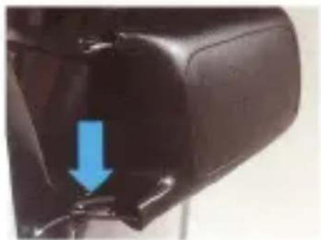
900 Convertible: If subjected to excessive force, the door mirrors will fold back. They can also be parked in this position. Carefully fold the mirror backwards until it engages the catch. To release the mirror, press it back and push in the catch.
If subjected to excessive force, the mirrors fitted to Convertibles will fold back. The mirrors can also be parked in the folded back position. Carefully fold the mirror backwards until it engages the catch. To release the mirror, push it further into the folded position to take pressure off the catch. Push in the catch and release the mirror.

Front reflect and clear lighter 5G 656
1 Spring catch
2 Cigar lighter
Ashtrays
The car is fitted with two ashtrays: one is incorporated in the radio console and the other at the back of the centre console between the front seats.
To remove the front ashtray from its housing, depress the spring catch (as shown) and pull the ashtray out of the housing. To replace the ashtray, simply push it back into the housing.
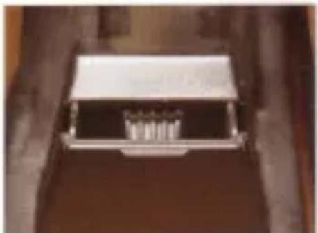
To remove the rear ashtray, make sure it is fully open and then press down and pull it forward. To refit the ashtray, engage the two springs in the corresponding lugs, press down on the ashtray and push it in
natural_image
Close-up of a metallic electronic component with internal structure (no visible text or symbols)Hear ashtray 50,685
natural_image
Close-up of a black electronic device with control buttons and red connectors, mounted on two purple cylindrical tanks (no visible text or symbols)Switches for electric windows and switch to render door switches for rear windows inoperative 801116
Electric windows

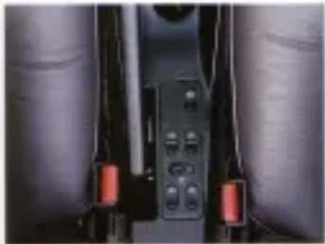
The two-position rocker switch-electric windows are located on panel on the centre console. The or the front-doors window have a sign beyond the spring-loaded device. With the switch in this post-window will open fully without the keep the switch depressed. Door are also provided for operation of windows but these can be re-operative by a switch on the centre marked ON/OFF to prevent childing with them.

natural_image
Simple line drawing of a door with a rectangular vent and a wall-mounted electrical outlet (no text or symbols)Door switch for rear window
50 217
WARNING
Always remove the ignition key when leaving the car to avert the risk of injury arising from unattended children operating the windows.
natural_image
Close-up of a white surface with a small rectangular object on top (no text or symbols visible)Sunroof handle
5599
Sunroof
To open the sunroof: slide the panel back by means of the handle. Release the handle when the sunroof is open the desired amount, whereupon it will lock in that position. To close the sunroof: slide the panel forward by means of the handle, making sure that it clicks shut.

natural_image
Close-up of a mechanical device with blue arrow indicating a component (no visible text or symbols)Switch for electric sunroof 801116
ROOF Some models are equipped with an electric sunroof. The switch for the sunroof is located at the front of the centre console.
Manual operation of suitroof

natural_image
Close-up of a metallic mechanical component with no visible text or symbols2023.08.1
A manual winder for emergency operation of the sunroof (e.g. in the event of an electrical fault) is fitted to the sunroof motor. The motor is located on the right-hand side underneath the luggage compartment floor.
To close the sunroof, rotate the vinder in a clockwise direction.
Convertible top
GENERAL SAFETY PRECAUTIONS
- When raising or lowering the top, keep hands well clear of the hinges, linkages and windscreen frame.
- Remove all objects from the space behind the rear seat before raising or lowering the top. This space is for slowage of the top only. Loose items left here could damage the rear screen or the top assembly.
Before raising or lowering the top, check that people are standing well clear. The rear seat must not be occupied during operation of the top.
■ Before lowering or raising the top, remove any child seats, carrycols, children or infants from the rear seat. -
Do not operate the top when the outside temperature is below 35°F (2°C).
-
Before driving off, make sure that the top is either properly secured to the top of the windscreen on both sides, or that it is properly stowed behind the rear seat.
- Before operating the ROOF switch, make sure that the manual valve is closed.
- Do not run the car through an automatic car wash as this is liable to damage the top.
- Do not lower the top when it is wet or damp as moisture can damage or stain the interior or cause mildew to form on the fabric of the top.
The 900 Convertible is designed for a maximum of four occupants including the driver, two in the front and two in the back.
It is strongly advised that rear-seat passengers also wear seat belts at all times.
Lowering the top
CAUTION
Keep hands well clear of the hinges and linkages when lowering the top.
Before lowering the top, make sure that the rear seats are unoccupied and that people are well clear of the car.
Remove any loose items from the space behind the rear seats (this space should not be used for storage other than for storage of the top itself).
Note that the rear screen must either be raised and secured with the zipper or lowered entirely into the space behind the rear seats. Never leave it resting horizontally against the rear-seat backrest.
1 Apply the handbrake. (The top cannot be operated unless the handbrake is on.).
2. Turn the ignition key to the drive position.
3 Lower all side windows and the sun visors.
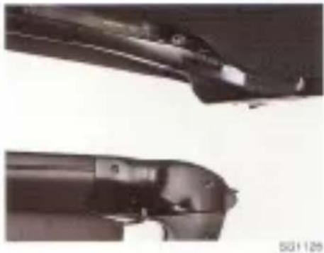
4 Undo the two latching handles, to release the hooks from the strikers.
5 Press the ROOF switch to raise the top to the position at which it will remain open (approx. 1 - 2 last (30 - 60 cm) above the windscreen frame).

1 Hack
2. Striker
Switch for Convertible Top

natural_image
Close-up of a hand pressing down on a dark object, possibly a button or component (no visible text or symbols)20184
natural_image
Close-up of two mechanical components with no visible text or symbols- Return the two handles to their original positions.
N.B.
Failure to do so at this stage can result in damage to the handles or the car upholstery.
7 Press the roof switch to lower the top completely. Switch off the ignition.
8. Check that the inner lining of the top has folded down properly behind and clear of the top edge of the backrest. If not, tuck it down by hand.
Fitting the side cover panel 90-167

natural_image
Close-up of a thin, dark object against a light background (no visible text or symbols)Securing straps for middle panel 50 928
the panel to engage the studs. Hook the straps onto the studs on the front of the panel.
CAUTION
Make certain the cover panels are secure before driving off.
Fitting the cover panels
Open the boot, unhook the elastic straps at either end of the storage bag and take out the covers.
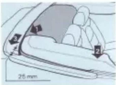
Inspect and, if necessary, clear any dirt from the groove in the black metal rail at the back of the stowage compartment (1).
Starting with the panel for the right-hand side, insert the rear edge into the groove in the black metal rail, positioning the panel approximately one inch (25 mm) in from the end of the rail. Press down the front of the cover [2] until it straps into place and is retained by the spring clip. Slide the back into position, in line with the black rail (3).
Fit the left-hand cover panel in the same way.
natural_image
Silhouette of a wooden structure against a warm-toned sky, possibly a lampshade or industrial lamp (no text or symbols visible)SG ID
N.B.
Make certain that the inner lining of the top does not become trapped between the panels and top of the backrest.
With the boot lid open, slide the edge of the middle cover panel under the metal rail and line up the studs with the corresponding fasteners in the side cover panels. Insert the straps on the back of the cover under the boot lid and close the lid. Push down on

natural_image
Close-up of a mechanical component with a blue arrow pointing to a small feature (no visible text or symbols)Fastener for middle panel stud 80 929
To remove the covers
Open the boot, unhook the straps from the front of the middle panel and ease the panel studs out of the fasteners. Raise the leading edge and remove the panel. To remove the side panels, release the back edges first.
Slow the cover panels in the bag (see instructions inside the bag).
Raising the top
CAUTION
Keep hands well clear of the hinges and linkages when raising the top.
Before raising the top, make sure that the rear seats are unoccupied and that people are well clear of the car.
1 Apply the handbrake. (The top cannot be operated unless the handbrake is on.)
2. Lower all side windows and the sun visors, and remove the cover panels.
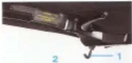
3 Press the ROOF switch and raise the top to halfway. Thereafter, lower it gently until it is approx. 2 feet (60 cm) above the windscreen frame (to prevent the top closing too soon with ensuing damage to the latching hooks).
4 Open the latching handles fully.
5 Press the ROOF switch again until the top comes to rest on the windscreen frame.
6 With one hand on the grab rail at the front of the top, hold the top firmly against the windscreen frame and lock the top by pushing the latching handles fully home.
N.B.
Do not pull the top down by means of the latching handles.
7 Check that the hooks are properly engaged.
natural_image
Close-up of a mechanical component with labeled parts 1 and 2 (no readable text or symbols)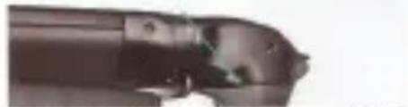
natural_image
Close-up of a mechanical component with no visible text or symbolsLatching handle 831127 1 Hook 2 Stiker
Latching mechanisms in locked position

natural_image
Close-up of a car interior showing a black plastic object and a white seat (no visible text or symbols)801125

natural_image
Interior view of a car with two blue arrows pointing to the roof and window (no text or symbols visible)Tap lining held in position by Veloro stop
8 If necessary, adjust the Velcro fastening along the edges of the top lining (see picture).
9 Switch off the ignition.
Raising the top manually
If necessary, in the event of a system failure, the top can be raised manually once a hydraulic valve (behind a flap in the trim at the back of the boot) has been opened.
CAUTION
Keep hands well clear of the hinges and linkages when raising the top.
Before raising the top, make sure that the rear seats are unoccupied and that people are well clear of the car.

natural_image
Close-up of a black circular object on a red rectangular base, with no visible text or symbols.Valve for manual operation of the lap.
1 Apply the handbrake.
2 Lower all side windows and the sun vis- sors.
3 Open the manual valve fully by turning the handle a quarter-turn clockwise.
4 Remove the cover panels and stow them inside the bag. Do not secure the bag in the boot yet.
5 From the rear seat, grip the grab rail on the front of the top and raise the top to the halfway position.
6 Open the latching handles fully.
7 Pull the top down onto the windscreen frame.
8 With one hand on the grab rail at the front of the top, hold the top firmly against the windscreen frame and lock the top by pushing the latching handles fully home.
N.B.
Do not pull the top down by means of the latching handles.
9 Check that the hooks are properly engaged.
10 If necessary, adjust the Veloro fastening along the edges of the top lining (see picture).
11 Fully close the manual valve by turning it a quarter-turn anti-clockwise.
12 Secure the bag in the boat.
Latching mechanism in locked position

natural_image
Close-up of a black mechanical component with a handle and bracket, mounted on a dark surface (no visible text or symbols)261185
Lowering the top manually
If required, in the event of a system failure, the top can also be lowered manually, once the hydraulic valve located behind a flap in the trim at the back of the boot has been opened.
CAUTION
- Keep hands well clear of the hinges and linkages when lowering the top.
- Before lowering the top, make sure that the rear seat is unoccupied and that people are well clear of the car.
- Remove any loose items from the space behind the rear seat (this space should not be used for storage other than for storage of the top itself).
- Note that the rear screen must either be raised and secured with the zipper or lowered entirely into the space behind the rear seats. Never leave it resting horizontally against the rear-seat back-rests.
1 Apply the handbrake.
2 Lower all side windows and the sun vis- sons.
3 Open the manual valve fully by turning the handle a quarter-tum clockwise.
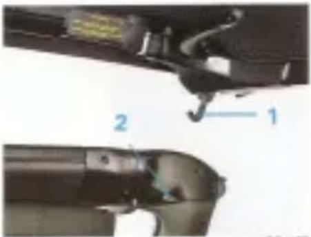
4 Open both latching handles fully.
natural_image
Close-up of mechanical components with numbered annotations (1 and 2), no readable text or symbols beyond labelsLatching handle
1 HOOR
2 Striker
5 Holding the grab rail at the front of the top, partly raise the top and then return the latching handles to the closed position.
6 From the side of the car, with the open palm of the hand under the side of the top frame, lift the top towards the back. Keep hands well clear of the linkages.
7 Push the top right the way down behind the rear seats.
8. Fully close the manual valve by turning it a quarter-tum anti-clockwise. Replace the trim panel over the valve.
9 Fit the cover panels as detailed earlier in this section.

natural_image
Close-up of a metal bracket with a small protrusion, mounted on a plain wall (no text or symbols visible)Support strap for rear screen
921 984
Opening the rear screen
The rear screen can be opened to provide a greater flow of air through the interior when the side windows are down. Open the rear screen as follows:
! Support the screen by securing the strap to the hanger.
2 Release the lining flaps on either side adjacent to the screen.
3 Open the zipper completely.
4. Undo the strap and lower the screen carefully down behind the rear seats. Re-secure the lining flaps.
CAUTION
To prevent damage to the rear screen, never store any hard or sharp objects behind the rear seats.
Raising the rear screen
1 Open the latching handles at the front of the top to release the tension in the fabric.
2 Release the lining flaps on either side, adjacent to the rear screen.
3 Lift the rear screen into position, securing it by means of the strap.
4 Close the zipper and re-secure the lining flaps.
5 Close the latching handles.
Zipper for rear screen

natural_image
Close-up of a mechanical component with a small insect on top (no visible text or symbols)电话:9600
Checking the level of the hydraulic fluid (Convertible)
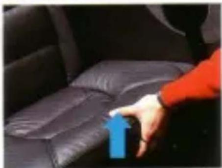
The reservoir is located underneath the rear seat. To remove the seat cushion, grip the front of the seat and lift it up.
The reservoir is transparent to facilitate checking of the fluid level. The level should be above the mark when the top is down, and below the mark when the top is up. If the level is low, do not add any fluid yourself. Contact an authorized Saab dealer, who will check the system for leaks and top it up with the special fluid required.
Removing the seat cushion
natural_image
Close-up of a hand pressing down on a dark leather car seat, with a blue arrow indicating the pressure point (no text or symbols visible)SG1128

natural_image
Close-up of a mechanical component with wires and a metallic body, resting on an orange surface (no visible text or symbols)Hydraulic-fluid reservoir
SIG131
Audio equipment
A cable for the car rental has already been run in all models of the Saab 900. In some models, cables have also been run for an electric aerial, or complete with electric aerial, and front and rear sets of speakers. The cables are accessible behind instrument panel console, the speaker cover on the instrument panel and behind the trim in the luggage compartment.
Further details of these and other accessories are contained in a leaflet available from your Sess dealer.
- Saab 900
- Owner's Manual
- Saab 900 M 1992
- Instruments and controls
- Main instrument display panel
- Indicator and warning lights
- Fuel injection system warning light
- Indicator light for rear-window heating
- Oil pressure warning light
- Charging warning light
- Main beam indicator light
- Rear fog lamp indicator light
- Handbrake warning light
- ABS warning light (option)
- Brake warning light
- WARNING
- Fuel gauge (FUEL)
- Fuel warning light
- Instruments
- Clock
- Rev counter
- Speedometer, millimeter and trip meter
- Temperature gauge
- Pressure gauge (900 Turbo 16)
- Switches
- Headlights and parking lights
- Note!
- Headlight beam-length adjustment
- Note
- Direction indicators
- Reversing lights
- Instrument illumination
- Interior lighting
- Luggage compartment light
- Rear log light (certain markets)
- Hazard warning lights
- Stalk switch for wipers and washers
- Heated rear window
- Heated driving seat
- Heating and ventilation system
- Heating and ventilation controls
- Fan
- Temperature control
- Air vents
- BOSTR
- Air distribution control
- Recommended control settings
- Misted windows
- Air conditioning (when fitted)
- Climate system tips
- Interior equipment
- Seats
- Head restraint
- Electrically adjustable seats
- Seat belts
- CAUTION
- WARNING:
- Child safety
- Child restraint anchorages, 900 Convertible (Australia only)
- Rear-view mirrors
- Ashtrays
- Electric windows
- Sunroof
- Convertible top
- GENERAL SAFETY PRECAUTIONS
- Lowering the top
- N.B.
- Fitting the cover panels
- To remove the covers
- Raising the top
- Raising the top manually
- Lowering the top manually
- Opening the rear screen
- Raising the rear screen
- Checking the level of the hydraulic fluid (Convertible)
- Audio equipment
Marque : SAAB
Modèle : 900 (1992)
Catégorie : Voiture