
9000 (1998) - Voiture SAAB - Notice d'utilisation et mode d'emploi gratuit
Retrouvez gratuitement la notice de l'appareil 9000 (1998) SAAB au format PDF.


| Type de produit | Voiture |
| Marque | SAAB |
| Modèle | 9000 |
| Année de fabrication | 1998 |
| Catégorie | Berline |
| Longueur | 4780 mm |
| Largeur | 1760 mm |
| Hauteur | 1420 mm |
| Empattement | 2670 mm |
| Poids à vide | 1450 kg |
| Motorisation | Essence Turbo 2.3 L |
| Puissance maximale | 170 ch |
| Transmission | Manuelle 5 vitesses ou Automatique 4 vitesses |
| Carburant | Essence sans plomb 95/98 |
| Capacité du réservoir | 68 L |
| Volume du coffre | 500 L |
| Consommation mixte | 9.5 L/100 km |
| Freins avant | Disques ventilés |
| Freins arrière | Disques |
| Équipements de sécurité | ABS, airbags conducteur et passager, ceintures 3 points |
| Pneus | 195/60 R15 |
| Entretien routine | Vidange tous les 15000 km, courroie de distribution tous les 90000 km |
| Disponibilité pièces détachées | Pièces d'origine SAAB et après-vente |
| Réparabilité | Manuel de réparation disponible |
FOIRE AUX QUESTIONS - 9000 (1998) SAAB
Questions des utilisateurs sur 9000 (1998) SAAB
0 question sur cet appareil. Repondez a celles que vous connaissez ou posez la votre.
Poser une nouvelle question sur cet appareil
Téléchargez la notice de votre Voiture au format PDF gratuitement ! Retrouvez votre notice 9000 (1998) - SAAB et reprennez votre appareil électronique en main. Sur cette page sont publiés tous les documents nécessaires à l'utilisation de votre appareil 9000 (1998) de la marque SAAB.
MODE D'EMPLOI 9000 (1998) SAAB
Saab 9000
Owner's Manual
1 9 9 8


SAAB
Owner's Manual
Saab 9000 M 1998
Instruments and controls 5
Interior equipment 41
Doors, locks and luggage compartment 59
Starting and driving 69
Car care and maintenance 89
Technical data 115
Index 131
© Saab Automobile AB 1997
Service Readiness, Saab Automobile AB, Trollhättan, Sweden
Printed by: Graphic Systems AB, Göteborg

SAAB
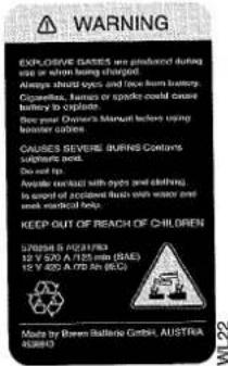
Warning labels

Battery:
Contains corrosive sulphuric acid (40%).
• Produces EXPLOSIVE GASES when in use or being charged.
• Always shield eyes and face when working with battery.
• Cigarettes, naked flame and sparks can cause battery to explode.
• See the Owner's Manual before using jump leads.
- The battery can CAUSE SEVERE BURNS from the sulphuric acid it contains.
- Do not tilt the battery.
- Avoid contact with eyes, skin and clothes.
- In case of accident, rinse immediately with water and seek medical attention.
KEEP OUT OF REACH OF CHILDREN
A/C system:
Refrigerant under high pressure.
Do not loosen or remove the A/C system fittings before purging the A/C system. Incorrect service methods may cause injury to personnel. SYSTEM TO BE SERVICED BY QUALIFIED PERSONNEL ONLY. For instructions, consult the Service Manual.
The A/C system complies with SAE J639.
Charge: 950 g R134a.
Compressor oil: 200 cc PAG Oil SK 20 or SAAB oil 4319752.


natural_image
Side view of a sedan driving on a road with hills in the background (no visible text or symbols)the right to incorporate modifications and alter specifications during production without prior notice.
Best wishes,
Saab Automobile AB
The radio shown in some of the photographs in this booklet is not included as standard equipment for the car.
Introduction
This Owner's Manual provides advice on driving and taking care of your Saab car. The Saab 9000 models have the following range of engines:
Fuel injection engine, 2.0 litres or turbocharged engine, 2.0 t, 2.3 t and 2.3 Turbo.
The manual, which covers the most importance differences in the 9000 model range, is not intended to provide an exact specification of all model variants.
Read through the manual before taking the car out for the first time and then keep it in the car for future reference.
A list of contents is provided for each section of the manual and there is also a comprehensive index at the back.
Supplied with the car is a service book, which also contains important information on warranty conditions.
WARNING
WARNING indicates the possibility of personal injury if you do not follow the instructions described in the text under this heading.
IMPORTANT
IMPORTANT indicates the possibility of damage to your Saab if you do not follow the recommendations described in the text under this heading.
Since the policy at Saab Automobile AB is one of continual improvement, we retain

SG1286
Instruments and controls
Indicator and warning lights 6
Instruments 9
Trip computer 10
Switches 15
Manual heating and ventilation system 19
Automatic climate-control (ACC) system 21
Audio System (option) ...... 27

Main instrument display panel
1 Rev counter
2 Direction indicator repeater light
3 Speedometer incorporating odometer and trip meter
4 Temperature gauge
5 Pressure gauge (not models with a light pressure turbo engine)
6 Fuel gauge
7 Pictogram
8 EDU trip computer display
9 Trip meter reset knob
10 Indicator and warning lights
Indicator and warning lamps
All the warning lights come on as the ignition is switched on. The lights should all be extinguished as soon as the engine has been started.

Main beam indicator light
This light will show when the main beam is on, see page 15.

Washer fluid indicator light
This light will comes on when the washer fluid in the reservoir needs replenishing, see page 99.

ABS warning light
This light comes on if a fault arises in the Anti-Lock Brake System. Conventional braking will still be available but without the Anti-Lock System.
Have the Anti-Lock Brake System checked by an authorized Saab dealer without delay

Charging warning light
This light will come on if the battery is not being charged. If it comes on while you are driving, stop the car immediately and switch off the engine.
Check the engine drive belt. A broken belt means that the engine will not cool properly, the battery will not be charged and power steering will be lost.

Indicator lamps, fuel gauge
The lamp under the fuel gauge lights when there is less than 10 litres (2 imp. gal) of fuel left in the tank.
IMPORTANT
If you run out of petrol the catalytic converter could be damaged through air following along with the fuel, causing the temperature of the catalytic converter to increase by such an amount as to seriously damage it.

Rear fog lamp indicator light
This lamp lights up when the rear fog light is on, see page 16.
The rear fog light goes out when you switch off the engine. When the engine has been started, you will have to press the rear fog light switch to turn on the rear fog light again.

Warning lamp, handbrake
This light will show when the handbrake is applied.
WARNING
Always apply the handbrake before taking out the ignition key.

Indicator for headlights and parking lights
Symbol illuminated when the headlights or parking lights are on.

Indicator lamp, Cruise Control System
The lamp is lit when the cruise control is engaged.

Brake warning light
The lamp comes on when the level of the brake fluid in the reservoir is too low. If the lamp comes on when you are driving the car, stop immediately and check the brake fluid level.
WARNING
Never drive the car when this warning lamp is on.
The brake system should be inspected and put right immediately by an authorized Saab garage.

Indicator light for rear-window heating
This light will show when the rear-window heating is switched on, see page 20.

Oil pressure warning light
This light will come on if the engine oil pressure should fall too low. If the light flashes or comes on while you are driving, stop the car immediately, switch off the engine and check the oil level.
The car must not be driven while this light is on.
Pictogram
The pictogram will indicate if any door, including the boot lid, is not properly closed and if a bulb for the dipped headlights, stop lights or rear lights has blown. The picto-
Pictogram

gram also incorporates the oil pressure warning light.
When the ignition is switched on the two right-hand lamps in the pictogram will light up. They will remain on until you depress the brake pedal. If the lights do not go out when the brake pedal is depressed, then one of the brake light bulbs has failed.

Warning light for airbag - Supplementary Restraint System (SRS) (option)
The lamp flashes or remains on continuously when a fault arises in the SRS system.
The light will light up for a few seconds when the ignition switch is turned to the start or drive position, but should be extinguished when the engine has started.
WARNING
The fault might result in the SRS not being activated in a collision and the system should be checked without delay by an authorized Saab garage.
Instruments
Tachometer
The rev counter shows the engine speed in thousands of revs per minute. For maximum fuel economy, the needle should be kept within the green zone. The needle may briefly enter the broken red zone but must never be allowed to enter the solid red zone.
A safety cut-out function (fuel shut-off) prevents the engine speed exceeding approximately 6,000 r/min.
Speedometer, odometer and trip meter
The odometer records the distance in kilo-metres and the trip meter the distance in kilo-metres and tenths.
Pressure gauge (2.3 Turbo only)
The pressure gauge indicates the pressure in the intake manifold. When the engine is only lightly loaded and during engine braking, negative pressure will be present in the intake manifold and the needle on the gauge will then be in the white zone. At higher engine speeds and when the engine is under a greater load, the turbocharger will boost the pressure in the inlet manifold and the needle will enter the orange zone. Under normal conditions, the needle should not enter the red zone as a safety cut-out system will limit the charging pressure to protect the engine. However, under certain atmospheric conditions, the needle may just enter the red zone, which does not mean that the system is malfunctioning in any way.
But if the needle repeatedly enters the red zone and a loss in engine power is also experienced because the safety cut-out system is limiting the charging pressure, the car should be taken to an authorized Saab workshop without delay.
Temperature gauge
The temperature gauge indicates the temperature of the coolant. The needle should normally be in the middle of the scale.
If the temperature gauge needle approaches the red section (this may occur when the ambient temperature is extremely high or at very high engine loads), the highest possible gear should be selected to reduce the engine speed as much as possible. Avoid changing down. If the pointer should move into the red section in spite of these measures, stop the car and let the engine idle. If the needle repeatedly enters the red zone, stop immediately and check the level of the coolant. Turbo models: CHECK RADIATOR LEVEL will appear on the trip computer display if the coolant level in the expansion tank is too low.
Clock
The clock, situated to the right of the main instrument display panel, can be set to the correct time by means of the knob in the middle of the dial.
IMPORTANT
Consult your Saab dealer before adding any additional wiring, as this could cause damage to Electronic Control Units in the car.
Trip computer
Your car is equipped with a trip computer and EDU (Electronic Display Unit). The SCC (Saab Car Computer) is available as optional equipment.
The EDU trip computer incorporates a varying range of functions, depending on the model variant of your car and its level of equipment. The two control buttons for the computer are below the clock, and there is an electronic display below the speedometer, providing the following information:
• Average fuel consumption.
• Current fuel consumption.
In manual cars, this function is displayed as a horizontal bar in the right-hand section of the display.
- Range of the car, based on the amount of fuel left in the tank and the average fuel consumption.
When the range falls below about 30 miles (50 km) and one of the other functions has been selected, the arrow on the display will start to flash.
- Outside temperature (Ice warning). If the outside temperature is between +3°C and -3°C when the ignition is switched on, it will automatically be displayed instead of battery voltage. The display will then continue to show the outside temperature until either another function is selected with the INFO button or the outside temperature rises above +6°C or drops below -6°C. The outside

Control buttons for the EDU trip computer
temperature function is also active when the car is driven on the road.
WARNING
Note that there may be ice on the road even if the temperature is above +3°C, especially on bridges and in shady stretches.
- Battery voltage.
The battery voltage will always be displayed after the ignition key has been turned to the drive position. On starting, the value of the lowest voltage recorded will be displayed. Once the car is running, the computer will revert to the last function selected. By noting the voltage drop on starting, an assessment can be made of the condition of the battery (additional
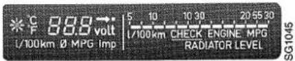
The EDU trip computer display (manual cars)

The EDU trip computer display (automatic cars)
information on the battery is given in the 'Battery' section).
These items of information are shown in the left-hand part of the display below the speedometer. To change the function of the display, press the INFO button repeatedly until the desired information is obtained.
The following warnings will be displayed automatically in the right-hand part of the display:
CHECK ENGINE
CHECK RADIATOR LEVEL
When you switch on the ignition, all three warnings should come on and then go off, one at a time, within about four seconds.
CHECK ENGINE comes on when a fault occurs in the fuel injection system or ignition system. The car can still be driven with
caution although its performance will be somewhat diminished, see page 72. The systems should be checked without delay by an authorized Saab garage.
CHECK RADIATOR LEVEL. This will come on if the level of coolant in the expansion tank falls too low.
PRND 321. On cars with automatic transmission, the selector lever position is indicated by an orange bar under the corresponding number or letter.
Changing units
To select the desired combination of units, depress the INFO and R buttons simultaneously and hold them depressed for at least four seconds. Each time the buttons are depressed, one of the four following groups of measurement units will be selected:
• litres/100 km, kilometres, °C
- MPG (US gal), miles, °F
- MPG (imp. gal.), miles, °F
- MPG (imp.gal.), miles, °C
Resetting
To reset the display for average fuel consumption and range of the car, depress button R and hold it depressed for at least four seconds. The appearance of - - - in the display indicates that it has been reset.
After resetting, calculation of the average fuel consumption starts afresh from 10 litres/100 km. The display will be reset automatically after 1,342 litres of fuel have been used or the car has been driven an aggregate of 6,512 miles (10,480 km).
Switching the display on/off
To switch off the display, press the R and INFO buttons simultaneously and release within four seconds.
The display will come on again if either of these buttons is depressed, if the ignition is switched on/off or if one of the check function warnings is initiated.
Error codes
If one of the trip computer sensors should develop a fault, ERR will appear on the left part of the display for a few seconds, immediately after the ignition has been switched on. The code will reappear if the function with the defective sensor is selected. Have the fault rectified by an authorized Saab workshop.

Trip computer SCC
SCC trip computer incorporates the following functions:
• DIST. TO DEST. (distance to destination)
• AVER. SPEED (average speed)
• SPEED WARN. (speeding alarm)
- CLOCK
• ARRIVAL (time of arrival at destination)
• ALARM
Use this button ing functions: DIST. TO DEST AVER. SPEED SPEED WARN

to select the follow-
Use this button ing functions: CLOCK ARRIVAL ALARM

to select the follow-
WARNING
The various SCC modes should be set while the car is stationary.
CLOCK
1 Select CLOCK


2


Hold the SET button depressed for two seconds (the figures will start to flash)
3


increase / decrease Set the desired time.
Press the appropriate button repeatedly until the required time is set. Hold the button depressed to change the figures more rapidly.
4


Depress the SET button briefly to end the setting procedure and start the clock. To reset the clock to zero, hold the SET button depressed for four seconds until the display shows 00.00.
The time can be displayed when the ignition is not switched on by pressing the INFO button on the SCC. The time will be displayed as long as the button is depressed.
ARRIVAL
This function is interconnected with DIST. TO DEST. and AVER. SPEED. You can find out your estimated time of arrival before starting on a journey by setting the distance to your destination (DIST. TO DEST.) and estimated average speed (AVER SPEED). To see your estimated time of arrival, select ARRIVAL.
The estimated time of arrival will then be adjusted continuously during your journey (after you have covered the first 500 metres), according to the average speed you maintain.
You can also see the average speed you must maintain in order to arrive at your destination at a particular time. You then enter the distance to your destination and the desired arrival time. This calculation can be performed as long as the DIST. TO DEST. is more than 0.
NOTE: This average speed will only be displayed if you subsequently select AVER.SPEED with the button 15 seconds of entering.
If you only set the distance to your destination, the estimated time of arrival will be displayed on the basis of your average speed after having driven 500 metres. Until you have covered 500 metres, the display will show - - - .
To set an estimated time of arrival on the basis of DIST. TO DEST. and AVER. SPEED, proceed as follows:
1 Select ARRIVAL

2 □ □ SET
Hold the SET button depressed for two seconds (the figures will start to flash).
3
decrease / increase
Enter the desired time of arrival. Press the appropriate button repeatedly until the required time is set. Hold the button depressed to change the figures more rapidly.
4 □ □ SET
Depress the SET button briefly to end the setting procedure and start the clock.
To clear the display, hold the SET button depressed for four seconds until the display shows - - - .
If the ARRIVAL function has been used in conjunction with DIST. TO DEST. and AVER. SPEED, the arrival time will be frozen when the DIST. TO DEST. countdown reaches 0.0.
The AVER. SPEED function continues to show your average speed.
ALARM
1 Select ALARM
2 □ □ SET
Hold the SET button depressed for two seconds (the figures will start to flash).
3
increase / decrease
Set the desired time. Press the appropriate button repeatedly until the required time is set. Hold the button depressed to change the figures more rapidly.
4 □ □ SET
Depress the SET button briefly to end the setting procedure and start the clock. The alarm beeps five times in five seconds followed by five seconds of silence.
This cycle is repeated five times.
The alarm sounds even if the ignition is not switched on.
The alarm is acknowledged by briefly depressing any of the SCC's three buttons. To activate an alarm time that has been set previously, hold the SET button depressed for two seconds until the figures start flashing, then briefly press the SET button.
To reset the alarm, hold the SET button depressed for four seconds until the display shows - - - .
DISTANCE TO DESTINATION
This function is interconnected with ARRIVAL and AVER. SPEED.
1 Select DIST. TO DEST.

2 □ □ SET
Hold the SET button depressed for two seconds (the figures will start to flash)
3
decrease / increase
Set the desired distance in kilometres Press the appropriate button repeatedly until the required distance is set. Hold the button depressed to change the figures more rapidly.
Set only whole kilometres.
4 □ □ SET
Press the SET button briefly to store the distance. The display now also shows tenths of a kilometre.
To reset the clock to zero, hold the SET button depressed for four seconds until the display shows 00.00.
If the DIST. TO DEST. function has been used in conjunction with AVER. SPEED and ARRIVAL, the countdown will stop at 0. The ARRIVAL time freezes when the countdown reaches 0.0.
The AVER. SPEED function continues to show your average speed.
The DIST. TO DEST. function cannot be calculated from AVER. SPEED and ARRIVAL.
AVERAGE SPEED
This function is interconnected with DIST. TO DEST. and ARRIVAL.
The average speed is displayed even if DIST. TO DEST. and ARRIVAL are not activated. Switching off the ignition does not reset the average speed function.
It is reset when DIST. TO DEST. is set.
To reset, hold the SET button depressed for four seconds until the display shows 0.
After resetting, the display will show your speed during the first 500 metres you cover and then the average speed for this distance. To enter an average speed which is to interact with DIST. TO DEST. or ARRIVAL, proceed as follows:
1 Select AVER. SPEED

2
Hold the SET button depressed for two seconds (the figures will start to flash).
3

decrease / increase Set the desired average speed. Press the appropriate button repeatedly until the required speed is set. Hold the button depressed to change the figures more rapidly.
4
Briefly depress the SET button to store the setting.
An average speed set in this way will change to the actual average speed after 15 seconds.
If the AVER. SPEED function has been used in conjunction with DIST. TO DEST. and ARRIVAL, AVER. SPEED will continue to display the average speed after DIST. TO DEST. has counted down to 0.
The ARRIVAL time is frozen in the display when DIST. TO DEST. has counted down to 0.
SPEEDING ALARM
The speeding alarm can be set between
1 - 200 km/h (1 - 125 mph).
1 Select SPEEDING ALARM
2 □ □ SET
Hold the SET button depressed for two seconds (the figures will start to flash).
3
decrease / increase
Set the desired speed. Press the appropriate button repeatedly until the required speed is shown. Hold the button depressed to change the figures more rapidly.
4 □ □ SET
Briefly depress the SET button to store the setting. A beep will sound every seven seconds whenever the car is travelling faster than the preset speed.
To deactivate the speeding alarm, hold the SET button depressed for four seconds until the display shows - - - .
To activate a previously set speeding alarm, hold the SET button depressed for two seconds until the figures start to flash, then briefly depress the SET button.
SELECTING THE UNITS
Hold the buttons depressed simultaneously for at least four seconds to change the groups of measurement units:
• km, km/h, 24-hour clock
• miles, mph, 12-hour clock (AM, PM).
Automatic conversion of the preset values takes place when the units are changed.
Switches
Parking lights and headlights

The lighting is off
Note that the instrument illumination is lit only when outside lights are on.
When you are towing a trailer, the lights switch should be set to Headlights.
Switch for parking lights and headlights

Parking lights
The parking lights can be switched on irrespective of the position of the ignition key. Parking lights should only be used when the car is stationary.

Headlights
The headlights can be switched on only when the ignition switch is in ON position. N.B. The headlights will be extinguished automatically when the ignition switch is turned to the LOCK position. The parking lights may still be switched on in this position.

Main/dipped beam
To change from main beam to dipped beam or vice versa, lift the stalk towards the steering wheel.
Headlight flashing
To flash the headlights, move the stalk towards the steering wheel. If the light switch is in the headlight position, change-over from main beam to dipped beam or vice versa will take place. In the OFF position, the main beam will be switched on until the stalk is released.
Headlight beam-length adjustment
Some variants are equipped with a system for adjusting the length of the beam from the headlights when this is affected by the
Switch for adjustment of headlight beam-length

way in which the car is loaded. The system comprises an actuator motor at each headlight and a switch on the fascia.
The switch, which must not be operated unless the ignition is on, has the following four positions:
| Posi-tion | Number of passengers | Load |
| 0 | One to three occupants (no more than one adult in the back) | and no luggage. |
| 1 | Two or three passengers in the back (and even a front-seat pas-senger) | a maximum of 30 kg of luggage. |
| 2 | Two or three passengers in the back | 40-90 kg of luggage in the boot |
| 3a | 1-2 | Maximum load in boot |
| 3b | 3-4 | Maximum load in boot plus a caravan or trail-er attached. |

Rear fog light
The rear fog light is located in the full-width light panel between the rear light clusters. It comes on when you press a switch on the dashboard, provided that your lights are on. The rear fog light goes out when you switch off the engine. When the engine has been started, you will have to press the rear fog light switch to turn on the rear fog light again.
Make sure that you are familiar with the law regarding the use of rear fog lights.
| WARNING |
| Avoid following the rear lights of a vehicle in front in conditions of poor visibility. If the vehicle in front brakes suddenly, it could lead to an accident and consequent injury. |
Direction indicators
To switch on the direction indicators, move the stalk up or down.
The stalk has a spring-loaded position for use of the indicators for changing lanes or overtaking. In the fixed position, the indicators will remain on until cancelled automatically by the steering wheel. The respective repeater light on the instrument panel will flash at the same rate as the direction indicators.
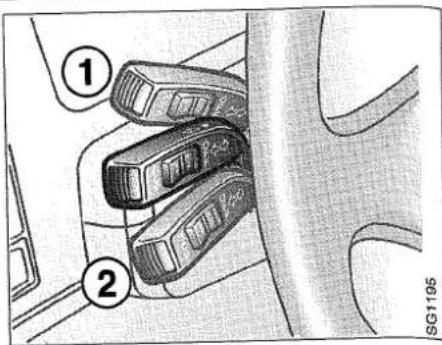
Stalk switch for main/dipped beam and direction indicators
1 Indicators for right turn
2 Indicators for left turn
If one of the double bulbs in the rear direction indicators burns out, the other bulb will flash at twice the normal rate.
Reversing lights
The reversing lights come on automatically when reverse gear is engaged.
Instrument lighting
The brightness of the instrument illumination can be varied by means of the dimmer control located on the left of the facia.

Hazard flashers
When the switch located to the right of the clock is depressed, all four direction indicators will flash simultaneously. An indicator light in the switch and both direction indicator repeater lights on the instrument panel will also flash.
Hazard warning light switch

natural_image
Interior view of a car dashboard with a circular warning symbol and a triangular warning icon (no text or symbols on the diagram itself)The hazard warning lights should only be used if, because of a collision or breakdown, the car constitutes a danger or obstruction to other road users.
The warning triangle is located under the floor of the luggage compartment.
WARNING
Do not forget to place a warning triangle on the road. It should be situated at the side of the road about 50-100 yards behind the car so that vehicles approaching from behind are warned in good time. Where visibility is limited, such as in a bend or on the crown of a hill, the triangle should be placed at a further distance from your car.
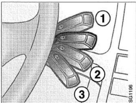
Stalk switch for wipers and washers
The stalk switch for the wipers and washers has the following positions:
1 Windscreen wipers, intermittent operation. The wipers will make a double sweep every few seconds. This function is particularly useful in light rain or drizzle.
2 Windscreen wipers, low speed.
3 Windscreen wipers, high speed.
For operation of the washers and wipers for the headlights and windscreen, lift the stalk switch towards the steering wheel. This function will operate irrespective of the position of the stalk.
Stalk switch for wipers and washers
Rear window wiper/washer
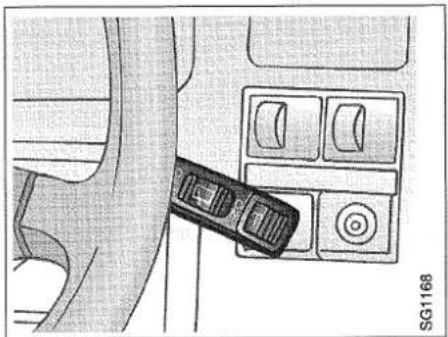
The rear window wiper/washer is operated by the same stalk as for the windscreen and headlamp wiper/washers.
This stalk has two additional positions, ON/OFF and ↑.
Select the ON position for intermittent operation.
Select the position ♂ for wash/wipe operation. After a few sweeps of the window the wiper will revert to intermittent operation if this has been selected.
Switch for rear window wiper and washer
natural_image
Interior view of a car dashboard with a car seatbelt switch and control panel (no text or symbols visible)Interior lightning
The lighting inside the car consists of a dome light, a light on the rearview mirror, a reading light for the front seat passenger, two reading lights for rear seat passengers and door lights on all doors. The respective door light comes on automatically when the door is opened.
The overhead panel incorporates the switch for the dome light and the front reading light and switch. The reading lights for the rear seat passengers incorporate their own switches. The reading lights can be switched on only when the ignition switch is in position ON.
The interior light has a delayed switch-off.
Switch for interior lighting
0 Lighting off
1 Lighting comes on when a door is opened
2 Lighting on continuously

natural_image
Technical line drawing of a mechanical component with no visible text or symbolsWhen the switch for the interior lights is in position 1, the lighting will be switched off either by a time-delay relay, 15 seconds after the last door has been closed, or when the ignition switch has been turned to position ON.
Luggage compartment lighting
The luggage compartment lighting is switched on/extinguished automatically when the luggage compartment door is opened/closed. The lighting can also be switched off by moving the switch to the middle position.

Fog lights
Some variants have extra fog lights integrated in the front spoiler. The switch is located under the headlight switch.
Make sure that you are familiar with the law regarding the use of fog lights.
Handbrake
The handbrake lever is situated between the front seats. The handbrake acts on the rear wheels. When the handbrake is applied, the indicator lamp in the main instrument display panel comes on. To release the handbrake, pull it up slightly and press the button. Then lower the lever. Always apply the handbrake when parking the car.
Manual heating and ventilation system
The air is evacuated through two air outlets, one on each side of the rear window.

Fan
The amount of air admitted to the car is controlled by the fan switch (four speeds). In position "0", the fan is switched-off. To increase the air flow, turn the switch clockwise.
TEMP
Temperature control
The temperature control provides infinitely variable control (between the limits) of the temperature of the supply air. Turn the knob clockwise to increase the temperature.
DISTR
Air distribution
The air distribution control is used to direct the supply air to the defroster, panel and floor vents.
The control may be set to a number of intermediate detent positions between the four main settings, to distribute the air between the floor and the defroster vents or between the floor and the panel vents.
Joysticks on the panel vents enable the direction of the air flow to be selected as desired (for instance, in very cold weather it may be advisable to direct the air flow onto the side windows to enhance the defrosting effect).
The knobs on the panel vents enable the amount of air admitted to be adjusted for each vent individually.
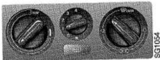
Manual-system controls

natural_image
Front view of a solar panel with three rotary dials and a grid-patterned top panel (no visible text or symbols)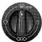
Maximum flow if air to windscreen and side windows (defroster position)
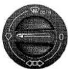
Maximum flow of air to floor

Maximum flow of air through panel vents

All vents closed

Heated rear window and door mirrors
The switch for the rear-window and door-mirror heating is incorporated in the control unit for the climate-control system. When the heating is switched on, an indicator light on the instrument panel will show.
Switch off the heating as soon as the rear window is free from ice and mist. The heating will be switched off automatically after 10-15 minutes.
Refrain from placing sharp or hard objects on the rear parcel shelf, to avoid damaging the heater wires. Do not switch on the rear-window heating before the engine is running.
The door mirrors have electrically heated glass. Heating is controlled with the same switch as the rear windscreen.
To obtain maximum heating in very cold weather
When starting the engine from cold, set the fan speed to position 2 and the DISTR control to the defroster position.
As soon as the needle on the temperature gauge has started to move up the scale, indicating that the engine is starting to get warm, increase the fan speed by moving the control to position 3. Once the wind-screen is clear, move the DISTR control one step to the left.
Obviously the time the engine takes to warm up depends on how the car is driven. It will take longer to heat up at low engine speeds, such as when the car is travelling fast on a motorway.
Do not use position 4 on the fan switch, as this is designed for use to blow air into the cabin for maximum cooling in hot weather.
Typical settings for different weather conditions

Winter - defroster

Winter - cloudy
Winter - sunny

natural_image
Three circular industrial control switches with labeled buttons (no readable text or symbols beyond labels)Summer - cloudy

natural_image
Three circular industrial air vent gauges with internal components, no visible text or symbolsSummer - sunny
Automatic climate control (ACC)
This system will maintain the desired temperature inside the car regardless of the ambient temperature.
Note that the system will automatically select the settings required to attain the desired temperature as quickly as possible. The car will therefore not heat up or cool down more quickly if you select a higher or lower temperature than that desired.
For optimum A/C performance the windows and sunroof, if fitted, should be closed.
Incoming fresh air is treated in three stages. First it is cleaned by an air filter, then dehumidified and cooled and finally heated, if desired.
The air is evacuated through two air outlets, one on each side of the rear window.
The temperature shown on the display is not the actual temperature inside the cabin: the system takes into account such factors as air flow, humidity, direct sun, etc. inside the car and then controls the climate to cor-
ACC control panel
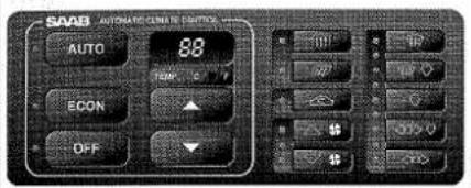
respond to the perceived comfort expected at the selected temperature.
- The normal range of settings is 19-23°C (66-73°F), depending on how cool/warm one likes it inside the car, and what type of clothes one is wearing.
- Ideally, changes to the selected temperature should be made in steps of 1^ .
- Temperatures can be selected within the range 17-27°C (63-80°F). There are also two other settings: HI (maximum heat and maximum fan speed) and LO (maximum cooling and maximum fan speed).
The system has four sensors:
- Ambient air temperature sensor (signal supplied by the EDU trip computer)
• Inside air sensor (located below clock)
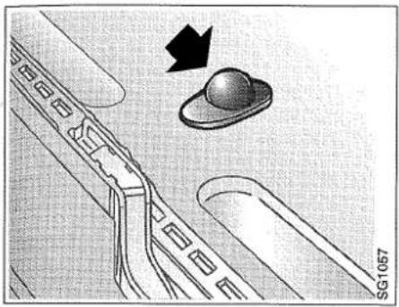
• Sun sensor (situated on top of the dash). - Blended air temperature sensor (in heater unit)
Take care not to obstruct the sun sensor, located midway between the defroster vents on top of the dash, as this can prevent the ACC system from functioning properly.
Rear door fan

natural_image
Diagram of a car's side window with arrows indicating airflow or movement, no text or symbols present
Air vents
Starting in cold weather:
Initially the system will automatically select rear-window and door-mirror heating, defroster setting, maximum heat and low fan speed.
To maintain or improve the distribution of cooled or heated air in the car, the system may in certain climatic/driving conditions briefly (max. 30 seconds) direct air to the floor vents.
As soon as the supply air is warm enough, air will be distributed through the floor vents and the fan speed increased.
As the cabin temperature approaches the temperature selected, the fan speed and heat supplied will gradually be reduced automatically to a suitable level.
Starting in warm weather:
Initially the system will direct fresh air through the panel vents at a high fan speed and will switch on the A/C compressor (unless the ECON button has been depressed).
To maintain or improve the distribution of cooled or heated air in the car, the system may in certain climatic/driving conditions briefly (max. 30 seconds) direct air to the floor vents.
Recirculation will be selected after about one minute if the ambient air temperature is above 27°C.
As the cabin temperature starts to approach the selected temperature, the fan speed will be reduced automatically to a suitable level.
Setting the required temperature
1 Switch on the ignition.
2 Select the desired temperature by means of the appropriate temperature button. The sliding control below the display panel can be used to select either the Celsius or the Fahrenheit scale.
3 The temperature you have selected is now stored in the microcomputer's memory and will be retained even when the ignition has been switched off. Next time you start the car, the microprocessor will automatically set the system to the temperature you selected last time you used the car.
Sun sensor
natural_image
Diagram of a mechanical component with a knob and arrow indicating direction (no text or symbols)Shows the selected cabin temperature
To increase the temperature
To reduce the temperature


Functions
Although the heating function for the rear window and door mirrors, and the rear-door fans are controlled automatically by the system, it is possible to override the system and switch these functions on or off by means of the appropriate button on the control panel, without affecting the comfort inside the car.
To cancel a function selected manually, press the button again or press AUTO. Once a function has been selected manually, it will remain in the selected mode, but all other functions will remain in the automatic mode.
Thus, control of the temperature will always be automatic. LED indicators adjacent to the function buttons indicate which functions are actuated.
AUTO
When this function is actuated, temperature, air distribution, fan speed, heating of the rear win-
dow and door mirrors, and air recirculation are controlled automatically. The air conditioning is automatically engaged if outside temperature is above +5°C. Pressing AUTO cancels all manually selected functions. However, manual selections that have been programmed in will be selected the next time the engine is started (see the section on ACC programming).
Instruments and controls
ECON
When this function is actuated, the A/C unit will not operate. Temperature, air distribution, fan
speed and rear-window and door-mirror heating will still be controlled automatically.
OFF
Pressing this button will switch the entire system off. To switch the system on again, press AUTO
or OFF again, in which case the last manual selections will be reactuated.

Heating of the rear window and door mirrors is controlled automatically, but can also be switched
on manually. In either case, the function will be switched off automatically after 10 or 11 minutes. The function can be turned off manually at any time.

The demister fans in the rear doors are controlled automatically and run at the same speed as the
main fan. The fans can also be switched off manually.

Air recirculation is controlled automatically but can also be selected or cancelled manually. Air
recirculation does not change the quality of the air significantly.
To increase the fan speed (stepless variation)
To reduce the fan speed (stepless variation)

Keep the button depressed until the desired fan speed is obtained.
The middle LED indicates that fan speed is controlled automatically, AUTO mode.
The two other LEDs indicate that fan speed has been selected manually:
increase fan speed - top LED lights up reduce fan speed - bottom LED lights up. Adjusting fan speed from minimum to maximum takes about eight seconds.

Defroster
When defrosting is selected manually, demisting of all windows will be obtained through higher fan speed, maximum air flow from the defroster vents and the vents in the rear doors, and operation of the electrically- heated rear window. Recirculation will be turned off if it has previously been selected.
The defrosting mode remains operative until another mode is selected, although the electrically-heated rear window will be switched off after about 10 minutes.
To return to the setting previously selected, press the defroster button once again.


Defroster/Floor
Air directed through the defroster and front and rear floor vents. A small amount of air will also be directed through the panel vents.

Floor
Maximum flow of air through all floor vents and a small amount of air through the defroster vents.

Floor/panel
Air through the panel vents and front and rear floor vents. A small amount of air will also be directed through the defroster vents.

Panel
Air only to the panel vents. A small amount of air will also be directed through the defroster vents.
Programming the ACC system
It is possible to save the functions selected manually by programming the ACC system. These functions will then be selected automatically each time the ignition is switched on. Note that you must wait at least 4 minutes after switching off the ignition before you can test the programmed functions.
1 Select the functions required.
2 Press and release

(As confirmation that programming has been carried out correctly, the brightness of the ACC display and LEDs will dim briefly and then return to full strength).
Cancelling ACC programming
To cancel the programmed settings, press and release OFF + AUTO simultaneously (the display and LEDs start flashing).
Hints and tips:
(before taking the car to an authorized Saab garage)
- If the LED by the AUTO button does not light up: see "Cancelling ACC programming".
- If the ACC system does not work satisfactorily: see "Calibration".
- If the battery has been disconnected or lost its charge, the ACC system will have to be recalibrated.
Calibration
If the power supply to the ACC system has been interrupted (e.g. battery disconnected), the system must be recalibrated. To recalibrate the system, press AUTO +
whereupon the indicator light at the side of will come on, indicating that calibration and self-testing are in progress. The right-hand array of indicator lights will then also come on, starting at the bottom and working upwards. During calibration, a '0' will appear on the display or, alternatively, a figure (1-5) indicating the number of faults detected. When calibration is complete, the ACC will revert to displaying the selected temperature. The calibration operation takes about 30 seconds.
Special climatic conditions
Misting and icing on the windows will not normally occur other than in extreme weather conditions, e.g. in heavy rain or cold weather, when humidity is unusually high or the occupants of the car are perspiring heavily or wearing damp clothes. If misting or ice on the windows is a problem under such conditions, the following action is recommended:
1 Select AUTO and a temperature of 21^ C ( 70^ F).
2 Select Defroster.
If this is not enough ...
3 Increase the fan speed. If this is not enough ...
4 Increase the selected temperature.

9000 Audio System (option)
The 9000 Audio System is specially matched to the cabin space in Saab 9000 models. It has a frequency response of 40 - 16000 Hz measured in the cabin.
The system consists of the following components:
• radio and cassette deck with switches and controls for the entire system
- 4 x 32 W amplifier located under the passenger seat
- Front and rear speakers
1 ON/VOL - on/off, volume
The system is switched on and off by pushing the ON/VOL button. When the system is switched on, the last settings are activated. Selected settings are saved when the system is switched off.
Volume adjustment with the ON/VOL button is of the so called endless type, which means that the button can be rotated with no stops. When the system is turned on the volume is the same as when it was turned off.

2 EQ/BAL Bass, treble, balance, fader
Press the EQ/BAL button to select the functions bass, treble, balance (left/right) and fader (front/rear).
Adjust the selected function with the plus/ minus button next to EQ/BAL:
| Bass | ±6 steps |
| Treble | ±6 steps |
| Balance | ±15 steps |
| Fader | ±15 steps |
If no more buttons are pressed, the system automatically returns to normal mode after 5 seconds.
3 EQ/BAL - Loudness
Press the button for at least 2 seconds to engage the Loudness function (louder reproduction of the lower tones).
4 BAND - Waveband selector
Press the BAND button to select the waveband:
$$ (F M 1 \rightarrow F M 2 \rightarrow F M 3 \rightarrow L W / M W). $$
5 Tuning and seek-tuning
Automatic seek-tuning:
Select sensitivity, LO (strong transmitters) or DX (strong and weak transmitters), by holding the TM button depressed for at least 2 seconds.
Press the button to tune up ▲ or down ▼ the frequency in the waveband selected with the BAND button (LO or DX is shown on the display during automatic seek- tuning). If the RDS and/or TA function (FM only) is engaged, the radio will only seek RDS and/or TA transmitters.
Manual tuning:
To switch to manual tuning, press the TM button.
To switch to manual tuning, press the TM button. Tune up ▲ or down ▼ to change the frequency. Manual tuning should start within 5 seconds, after which time the radio returns to automatic seeking.
A short press of the button changes frequency one step up or down. If the button is held down the frequency changes quickly.
Survey of display

6 Quick selection buttons 1-6
Press one of the buttons (1-6) to tune into a preset station.
If the button is held down (at least two seconds) it stores the station currently tuned and the previously set station is erased. The sound disappears during setting.
7 PS/AS- Automatic station memory
When the PS/AS button is held for at least 2 seconds, the radio automatically sets stations. The radio first seeks 6 strong stations. If less than six stations are stored during the first cycle, the radio searches for other stations at higher sensitivity.
If the RDS and/or TA functions are on when automatic station memory is started, the radio will only store stations with RDS and/or TA function.
The automatic storage of stations also works on the LW/MW band.
8 SOURCE - source selector
Press SOURCE to choose between radio, cassette and CD.
9 RDS - Radio Data System
RDS is an information system transmitted side-by-side with radio programmes on the FM network. Good reception conditions are essential for RDS to work well.
The signal from this type of FM transmitter enables the Audio System to automatically seek the strongest transmitter for the current programme and so maintain good reception irrespective of which transmitter is currently closest.
The RDS function is switched on and off with the RDS button. With RDS on, the display shows which programme you are listening to, for example BBC Radio 1. This is also the case with local radio stations, for example RADIO BRISTOL.
Flashing RDS means that the RDS information signal is too weak.
In this case you can press a present button to seek a stronger signal.
If you start a journey with the radio set to Radio 1, the radio will automatically change Radio 1 transmitter during the journey.
10 RDS - PTY function (Programme TYpe)
This function is based on the fact that programmes on the FM network are coded as to programme type. The PTY function is a sub-function of RDS.
Selection of programme type:
- Press the RDS button for more than 2 seconds (RDS should be activated)
- Using the buttons ▲▼, one can step between the different programme types 1 - 15. When required selection is reached this is activated after 5 seconds.
The following PTY can be selected:
• 1 - NEWS
• 2 - AFFAIRS
• 3 - INFO
• 4 - SPORT
- 5 - EDUCATE
- 6 - DRAMA
• 7 - CULTURE
• 8 - SCIENCE
• 9 - VARIED
• 10 - POP M
• 11 - ROCK M
• 12 - M.O.R.M. (Middle Of The Road Music)
• 13 - light music
• 14 - CLASSIC
• 15 - other music
The six preset programme types can also be selected using the quick selection buttons:
button 1 - NEWS
button 2 - INFO
knapp 3 - POP M
button 4 - SPORT
button 5 - CLASSIC
button 6 - M.O.R.M.
It is also possible to change the preset programme types on the quick selection buttons as follows:
- Hold the RDS button pressed for more than 2 seconds.
- Select programme type using the buttons ▲▼ (5).
- Press desired quick selection button for more than 2 seconds to store the selected type of programme.
When a PTY choice has been made, this type of programme will be received by the radio even if you are listening to another programme source (TAPE, CD or another FM station).
When a programme of a selected type is over, the audio system returns to the previously selected programme source and the radio waits for the next programme of the selected type.
If you want to interrupt the reception of a programme with the selected PTY code, press the SOURCE button. The radio then waits for the next programme with the selected PTY code.
Changing to another programme type after the PTY function is activated is achieved by pressing the RDS button for more than 2 seconds.
You then make a new selection using the quick selection buttons or the ▲▼ buttons. If a cassette or CD is playing when you choose a programme type, this recording will continue to play until the selected programme type is transmitted.
Cassette or CD playback will then be interrupted while the selected programme type is being transmitted. You can change between CD, TAPE and RADIO without affecting the PTY selection (do not select LW/MW as no RDS functions work on this waveband).
The PTY function is switched off by pressing the RDS button.
After the PTY function has been switched off the RDS button functions to switch the RDS function on and off.
11 TA - Traffic Announcement (traffic reports)
By activating the TA function with a press on the TA button, you enable any traffic reports to interrupt cassette/CD playback.
This function is independent of the RDS function. When a traffic report is transmitted, radio reception or cassette/CD playback is interrupted. The display shows "TRA INFO" and the volume is adjusted to a preset level (if the preset volume is lower
than the one you have yourself selected for playback, the volume remains unchanged). When the traffic report is over, playback resumes with previous settings.
TP - Traffic Programme
TP indicated on the display shows that the current transmitter can rely traffic messages.
If the current transmitter cannot relay traffic messages (no TP indicated on the display but TA function activated) an automatic search starts for a transmitter with TP transmission.
EON - Enhanced Other Network
(updated of other transmitter nets)
Updating of other transmitter nets is automatic provided the EON indicator is on (you cannot activate EON yourself).
If you are listening to Radio 1 during a journey, the Radio 3 frequencies will also be updated, even if you are not listening to Radio 3.
EON makes it possible to receive traffic messages and PTY signals sent over a transmission net you are not listening to.
Alarm interruption
With RDS activated, a programme source can be interrupted for important messages other than traffic information. In this case the display shows ALARM.
12 TA - REG (REGional)
If you want the radio to tune in to a preset local radio station only, activate the REG function by keeping the TA button pressed for more than two seconds (REG appears on the display).
The REG function is switched off by holding the TA button depressed for more than 2 seconds (REG disappears from the display).
When the REG function is switched off and you activate the preset button where the local radio station is stored, the radio searches for another local radio transmitter (PI SEEK). If the preset button is again pressed, the radio searches for the next nearest local radio transmitter.
Quick Guide - Radio
| Function | Button | Press | Sequence |
| Band selection |  | < 2 s | FM1 → FM2 → FM3 → LW/MW — |
| Sensitivity |  | > 2 s | DX → LO — |
| Frequency setting |  | < 2 s | AUTO → MAN — |
| Up the band |  | 87.0 → 108.0 — | |
| Down the band | [6HY9] | 108.0 → 87.0 — | |
| Sound profile | [246Z] | < 2 s | BASS → TREB → BAL → FAD — |
| Loudness | [23TA] | > 2 s | LOUDNESS—ON → OFF — |
| Scan preset | [3G4S] | < 2 s | FM1 → FM2 → FM3 — |
| Auto store |  | > 2 s | FM3 |
| RDS | [ATGA] | < 2 s | RDS ON → RDS OFF — |
| PTY |  | > 2 s | RDS ON—PTY ON → PTY OFF — |
| TA | [2DWZ] | < 2 s | TA ON → TA OFF — |
| REG |  | > 2 s | RDS ON—REG ON → REG OFF — |
Cassette player
Carefully insert a cassette into the aperture with the open side to the right. Radio and CD playback is interrupted and the system goes over to cassette playback.
Make sure that any labels on the cassette are not loose and that the cassette is not bent as this can cause the cassette to become jammed in the player.
During playback the display shows TAPE >> or TAPE <<, depending on which side of the cassette is being played.
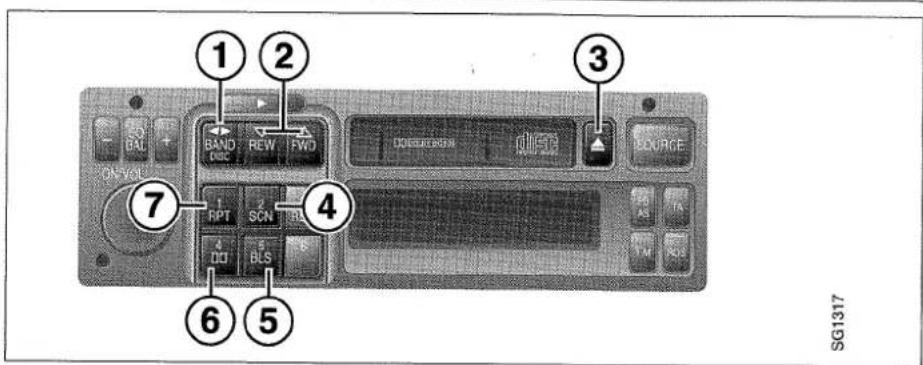
1 Cassette changeover
Cassette is manually changed over by pressing the BAND ◀▶ button.
The cassette is automatically changed over when one of the ends is reached during fast forward or playback. Playback of the other side of the tape begins.
2 Fast Forward, Rewind and Music Search
Press the FWD button to fast forward or the REW button to rewind.
If one of these buttons is pressed during fast forward or rewind, music search starts (APC appears on the display). Fast forward or rewind stops at the next piece, provided that this is preceded by a silent section of at least 4 seconds.
Fast forward and rewind, with or without music search, can be stopped by pressing the BAND button ◀▶.
Music search may not function properly in the following circumstances. This does not however mean that there is any fault.
- Tapes with gaps of less than 4 seconds between the different recordings. These are too short for the system to detect.
- Tapes with conversation where there are pauses of at least 4 seconds. The system interprets these as gaps in the tape.
- Recordings with very low level for at least 4 seconds. The system interprets these as gaps in the recording.
3 Cassette Eject button
Stop playback by pressing this button or by selecting another programme source (RADIO/CD) using the SOURCE button. When another programme source is selected the cassette remains in the player and the sound head and the pinch rollers are lifted from the tape. This also happens if the radio is switched off during cassette play-back. The eject also works when the radio is turned off.
4 SCN - 10 second playback of every track
Engage the function by pressing the SCN button (SCN shows on the display). Select FWD or REW (fast forward or rewind starts). Pressing FWD or REW one more time starts a 10 second playback of every
track. You can switch between FWD and REW while SCAN is running.
5 BLS - (BLank Skip)
When the BLS button is pressed during normal playback a forward music search starts (FF-APC appears on display) if the tape has a silent section of approx. 12 seconds.
Playback resumes when the player finds a recorded section.
6 Dolby ^® , noise reduction
Dolby B is activated with the button ☐. Cassettes recorded using Dolby should be played back with the Dolby function on.
7 RPT - (RePeaT) - Track repeat
Press the RPT button to repeat the track being played. RPT shows on the display. When the player is rewinding to repeat the track, REPEAT shows on the display.
Metal tapes
The cassette player has an automatic metal tape switch.
Cassette care
Do not expose cassettes to direct sunlight or very high or low temperatures as this can damage the cassette and the tape.
Always keep cassettes in the box when not in use.
Take the cassette out of the machine when not in use.
If a cassette jams in the machine, contact an authorized Saab workshop.
CD player (option)
IMPORTANT
A Compact Disc has a much wider dynamic range than an analogue record or musicassette tape. When playing a CD it is therefore advisable to turn the volume right down and then increase it gradually when the music starts. Do not turn up the volume suddenly as this could damage the speakers.
Driving on uneven ground or poorly surfaced roads may cause skipping of the sound. This is not harmful to either the CD or the player.
Only one CD at a time can be loaded. Insert the CD with the label side facing upwards or the CD player will eject it.
It is also possible to play 3" CDs without an adapter. When playing a 3" CD the display will show CD SINGLE. Do not use an adapter ring as this could damage the CD player.

Using the CD player
The CD player is switched on when a CD is inserted in the slot (2).
When ejecting the CD by means of the button (1), the CD player is switched off and the system reverts to radio mode.
Normal playing
Insert the CD in the slot (2) and the first track will be played. When the last track comes to an end the CD will be played from the beginning again.
Display
The display (3) shows the number of the track being played and the elapsed playing time of the current track.
On the right in the display are other mode choices:
Moving forward on the CD
- Press the ▶▶ (5) button for less than 2 seconds to go forward to the beginning of the next track.
- Press the button for more than 2 seconds to go forward at high speed.
Moving back on the CD
- Press the ◀◀ (7) button for less than 2 seconds to go back to the beginning of the current track.
- Press the button for more than 2 seconds to go back at high speed.
| Button No. | Press (seconds) | Function | Display shows |
| 6 | Playing stops. Press the button again and CD playing will be resumed at the point where it stopped. Switch to radio or cassette playing by pressing the SOURCE button. | PAUSE | |
| 8 | <2 | The track being played will be repeated until this mode is cancelled by pressing the button once again. | RPT |
| 8 | >2 | The tracks will be played in random order. | RDM |
| 4 | <2 | The first 10 seconds of each track will be played. This mode can be cancelled by pressing the button once again. | SCAN |
| 4 | >2 | The player goes back immediately to the beginning of the first track (TOP mode). |
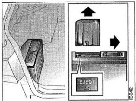
CD-changer in the boot

natural_image
Illustration of a hand holding a CD-ROM device with a close-up inset showing the cable being inserted (no text or symbols)CD Changer
Load the CD changer in the boot (1-6 discs) as follows:
1 Slide away the protective cover over the disc magazine.
2 Push EJECT and remove the magazine.
3 Insert the discs in the magazine slots (text up).
4 Load the magazine into the CD changer and slide back the protective cover.
When changing discs in the magazine, release already loaded discs by pressing in the locking arm. There is one locking arm for every disc slot.
Playing CD's
When a CD magazine has been loaded in the CD changer, playback will start at the first track of the first CD when CD is selected with the SOURCE button.
If CD is selected when the changer is empty, NO PACK shows on the display.
If the cassette player or radio is activated during CD playback, the CD player goes over to pause mode.
If CD playback is reselected with the SOURCE button, playback continues where it stopped.
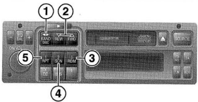
1 DISC
Disc change is achieved with the DISC button. If a disc slot is empty or if there is a fault with a disc the next disc in the magazine is activated.
2 FWD/REW
Pushing FWD (forward) makes the recording jump to the next track.
Pushing the REW button (reverse) makes the current track replay from the beginning. If either button is held down for more than 2 seconds, the disc is played fast forwards or backwards. This function continues for 5 seconds after the button is released. If the button is held for more than 5 seconds, fast playback is even faster.
Pressing one of these buttons when the CD changer is in RDM mode makes the player skip the current track. The RDM function remains.
3 RDM - (RanDoM) - Random playback
The RDM function is activated by pressing the RDM button. This starts random play-back of one disc at a time.
When all tracks on this disc have been played, random playback continues with the remaining discs in order. This function is switched off by pressing the RDM button again. The RDM function is also switched off when the SCAN button is pressed.
If FWD or REW is pressed during random playback, the CD player jumps to the next track and random playback continues.
Stop CD playback by choosing another programme source (RADIO/TAPE).
The CD player then goes over to pause mode.
4 SCN - 10 second playback of every track.
This function holds through the entire disc magazine. If the SCN button is pressed while the SCAN function is running, the CD player goes over to normal playback of the current track.
The SCAN function can also be cancelled by pressing one of the following buttons: FWD/REW, RDM, DISC, SOURCE, or if the radio is switched off.
5 RPT - (RePeaT) - To repeat a track or a whole disc
Press the RPT button to select the repeat of either one track (REPEAT TRACK is displayed) or a whole disc (REPEAT DISC is displayed). RPT is shown on the display when the function is activated.
SG1319
Anti-theft lock
The Audio System is equipped with two types of anti-theft lock.
On type is that a section of the radio panel containing 9 buttons (quick selection buttons etc) is detachable:
1 Switch off the audio system.
2 To release the detachable part, slide the rectangular switch (above the group of 9 buttons) to the right.
When this section of the panel has been removed, the radio cannot be used.
The other type of anti-theft lock consists of an electronic, four digit code lock. The code is on the code card delivered with the Audio System.
The four digit code is programmed at manufacture and cannot be changed. For this reason it is important to keep the code safe, but never with the unit. If code should be lost, contact an authorized Saab dealer to gain access to the code.
If the battery is disconnected, if the system is dismantled or for some reason disconnected, the four digit code must be entered using the quick selection buttons as follows:
1 Turn on the radio (display shows CODE IN)
2 Enter the four digit code using the quick selection buttons and the radio starts. If an incorrect digit has been pressed, a total of four digits must be pressed to make a new try possible. After all four figures have been pressed, hold the BAND button depressed for more than three seconds to clear the display. The display now shows CODE IN again and the correct code can be entered.
3 If the wrong code is entered three times in a row, wait an hour with the unit switched on before trying again. After waiting for one hour, the right code must be given on the first attempt otherwise you must wait another hour with the unit switched on before making a further attempt.
Telephone controlled lowering of volume
If a mobile telephone is installed in the car it can be wired so that the Audio System's volume is lowered when the telephone is used. Contact your Saab agent.
Adjusting the preset volume of traffic messages
The preset volume level can be adjusted if desired as follows:
1 Hold the TA button depressed as the radio is switched on (display shows VOL ADJUST).
2 Adjust volume.
3 Press any other button or wait 5 seconds to lock the volume at the new level.
Mobile telephone and communications radio
Mobile telephones and communications radios without separate outside aerials radiate an electromagnetic field in the cabin.
WARNING
• The radiated field in the cabin can dangerous to health
- The radiated field can cause interference in the car's electrical system
For this reason Saab recommends that you always attach your telephone / communications radio to an external aerial.
An external aerial will also improve transmitting and receiving conditions as well as giving your equipment a longer range.
For traffic safety reasons always stop your car in a suitable place when calling.
Mobile telephones and communications radios which are not part of Saab's standard equipment can interfere with the car's electronics system and give spurious warnings.
WARNING
• Always contact an authorized Saab workshop for fitting instructions.
- If you suspect an unclear fault warning/indication contact an authorized Saab workshop for checks.

natural_image
Interior view of a car showing three seats and dashboard (no text or symbols visible)Interior equipment
Seats 42
Steering-wheel adjustment 44
Seat belts 44
Airbag 46
Child safety 50
Rear-view mirrors 52
Electric windows 53
Sunroof 54
Illuminated make-up mirrors 54
Ashtrays 55
Audio equipment 56
Glove compartment...... 56
Can holder 57
Seats
On some markets the electric heating of the seat and backrest cushions of the front seats is individually adjustable and can be operated by means of the switch when the ignition switch is in the drive position.
The front seats can be adjusted for leg-room, the rake angle of the backrests has stepless adjustment and the head restraints can be raised or lowered. Apart from being adjustable for height, the driver's seat also has an adjustable lumbar support.
The front of the driver's seat can be raised and lowered (both front seats on certain model variants).
When adjusting the driver's seat, the following procedure is recommended:
First adjust the seat height, then the leg-room and after that the backrest rake angle. Finally, adjust the position of the steering wheel.
Head restraint
The front-seat head restraints can be raised or lowered to one of several preset positions.
WARNING
Test the head restraint thoroughly to be sure that it provides good support for th head. This is to prevent the danger of whiplash injuries in the event of a collision.
To adjust the head restraint
For best protection, the head restraint should be level with the occupant's head.
To raise the head restraint: grip it on either side and pull it straight up.
To lower the head restraint: press the top straight down.
Legroom adjustment
Lift the bar and slide the seat to the desired position. Release the bar and check that the seat is locked in the new position.
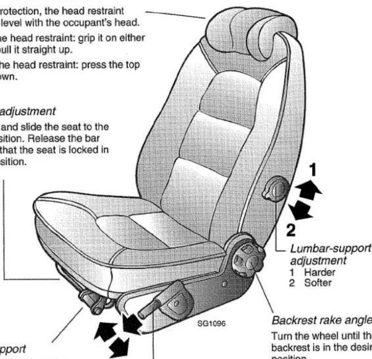
Thigh support
Lift the lever to raise the front of the cushion.
Height adjustment
Pull forward the telescopic lever and raise or lower the lever until the desired height is obtained.
Backrest rake angle
Turn the wheel until the backrest is in the desired position.
WARNING
The car must be stationary during adjustment of the driver's seat.
After legroom adjustment of a manually adjustable seat, a check should be made that it is locked in the desired position. Otherwise the seat might move out of position while the car is in motion and could be the cause of an accident. If the seat is not locked securely in the adjusted legroom position, it could be a contributory cause of serious injury in a collision.
When the car is being driven, the backrest should be in an upright position to ensure that the seat belt, airbag and backrest will provide the best possible protection during heavy braking or in the event of a collision.
Electrically adjustable front seats
Electrically adjustable front seats are available as an optional extra. The top control is for adjustment of the backrest. The lower control is for legroom adjustment and for individual height adjustment of the front (thigh support) and back of the seat.
After the seat has been adjusted by means of the ordinary controls, the seat setting can be stored in the memory by simultaneously pressing the memory (M) button and one of the position buttons 1, 2 or 3.
To activate the memory function, keep the required position button depressed while the seat is assuming its stored setting. If one of the three stored settings is to be altered, re-adjust the seat by means of the or-
Controls for electrically adjustable front seats
1 Backrest rake angle
2 Legroom and height adjustment
3 Memory functions
dinary controls, and then depress simultaneously the M button and the required position button.
The seats incorporate a safety function enabling them to be operated with the ignition switched off if a door is open. If the door is closed, however, the ignition must be switched on.
This feature makes it easier to enter the car while at the same time minimizing the danger of injury to children, for instance, as a result of playing with the seat.
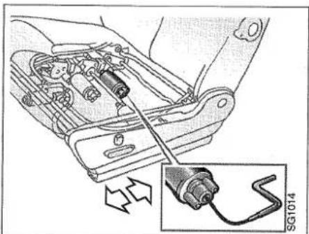
In the event of an electrical fault, a special winder included in the tool kit can be used to adjust the seat manually for legroom.
From underneath at the back of the seat, insert the winder in the electric motor (the one on the right-hand side, nearest to the back of the seat). Turn the crank clockwise to move the seat rearwards and counter-clockwise to move the seat forward.
Location of crank

natural_image
Mechanical assembly diagram showing a connector inserted into a vehicle's internal components, with an inset detail highlighting the cable (no text or symbols present)
Electrically heated driver's and co-driver's seats
The car has adjustable electric heating of both the driver's and the co-driver's seat cushion and backrest.
The heat output can be adjusted individually for each seat in three steps. In position 3, the heat output is a maximum, whereas in position 0, the heating is switched off.
Seat-heating controls

Steering wheel adjustment
Fore-and-aft adjustment of the steering wheel is possible after the handle has been turned to release the locking mechanism.
Move the steering wheel to the required position and then lock it by turning the handle back.
Seat belts
Seat belts should always be worn by all persons in the car. Surveys show that it is just as dangerous for rear-seat occupants not to wear seat belts as it is for front-seat occupants.
In the event of a collision, unrestrained rear-seat passengers are thrown violently forward against the front-seat backrests. This doubles the force put on the front-seat
Locking handle for the steering wheel
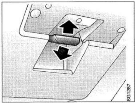
natural_image
Mechanical assembly diagram showing a cylindrical component inserted into a housing with directional arrows indicating motion (no text or symbols)occupants and seat belts, frequently resulting in injury to all the occupants.
Each belt may only be worn by one person at a time.
WARNING
- Seat belts are designed to bear upon the bony structure of the body, and should be worn low across the front of the pelvis, or the pelvis, chest and shoulders, as applicable: wearing the lap section of the belt across the abdominal area must be avoided.
- Seat belts should be adjusted as firmly as possible, consistent with comfort, to provide the protection for which they have been designed. A slack belt will greatly reduce the protection afforded to the wearer.
- Care should be taken to avoid contamination of the webbing with polishes, oils and chemicals, and particularly battery acid. Cleaning may safely be carried out using mild soap and water. The belt should be replaced if webbing becomes frayed, contaminated or damaged.
- It is essential to replace the entire assembly after it has been worn in a sever impact even if amage to the assembly is not obvious.
- Belts should not be worn with straps twisted.
• Each belt assembly must only be used by one occupant; it is dangerous to put a belt around a child being carried on the occupant's lap. - No modifications or additions should be made by the used which either prevent the seat belt adjusting devices from operating to remove slack, or prevent the seat belt assembly from being adjusted to remove slack.

natural_image
Illustration of a hand adjusting a belt buckle (no text or symbols visible)Front seat belt
Apart from the belt for the middle rear-seat passenger, the seat belts are of the inertia reel type. To fasten a seat belt, pull the strap gently out of the reel and insert the tongue in the lock. Make sure that the tongue is properly secured.
WARNING
The diagonal seat-belt strap must never be placed behind the body (i.e. run between the back and the seat backrest) or be pulled off the shoulder so that it runs under the arm.
The bottom anchorage points for the front seat belts are attached to the seat and therefore move with it when legroom is adjusted.

natural_image
Technical diagram of a vehicle interior showing internal components and airflow paths (no text or labels)Correct placement of seat belt
The seat belts for the front seats are equipped with automatic belt pretensioners which are activated in a severe head-on collision but not by lighter frontal impacts. They restrict the forward movement of the wearer in a collision.
Rear-end and side collisions do not activate the belt pretensioners, nor are they activated if the car rolls over
WARNING
Seat belts, seat-belt pretensioners and other constituent parts must be inspected after every collision by an authorized Saab garage.
Interior equipment
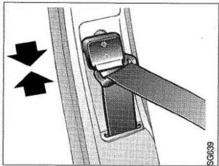
The height of the belt guide on the door pillar is adjustable. It is normally set in the upper position. This setting provides the greatest protection. On short persons, the diagonal strap may run too close to the neck. The belt guide can then be lowered until the strap runs across the body somewhat below the neck, to maintain the same level of protection.
To alter the height of the guide, squeeze the sliding piece as indicated by the arrows and move it to the desired position. Make sure that the guide is securely locked in the new position.
For maximum protection, the seat belt should be worn with the hip strap low across the hips and the diagonal strap well in on the shoulder but not too close to the neck. Make sure that the belt is not twisted
Belt guide on door pillar
natural_image
Mechanical diagram showing a belt buckle being inserted into a seatbelt, with arrows indicating direction (no text or symbols present)
natural_image
Medical illustration showing a hand holding a surgical instrument (no text or symbols visible)Lengthening the lap strap
or rubbing against any sharp edges and that there is no unnecessary slack in the straps.
Do not recline the backrest by too great an amount as the seat belt is designed to provide protection when the seat is adjusted to an ordinary seating position.
To release the buckle, press the red button marked PRESS.
Most of the time when the belt is being worn the reel will not be locked, thus allowing freedom of movement. However, the reel will lock if the strap is jerked or withdrawn sharply, if the car is tilted at a steep angle, or if the car is braked hard or is involved in a collision.
A seat belt warning light on the overhead panel will show if either of the front seat occupants has neglected to fasten his belt.
The belt for the middle rear-seat passenger is of the lap-belt type and can be adjusted manually. If required, lengthen the belt before fastening it by holding the adjuster at right angles to the strap and pulling the strap out.
Tighten the belt by pulling the free end until the belt fits snugly against the body. To release the belt, press the red button on the buckle.
Pregnant women
Expectant mothers should take care to fit the belt such that it does not apply pressure to the abdomen. The hip strap should be as low as possible across the hips.
WARNING
Make sure that the belts do not become trapped when the rear-seat cushion is tipped forward or folded back.
Airbag (SRS)
Driver's seat
The car's SRS (Supplementary Restraint System) consists of an airbag incorporated in the steering wheel. On some variants, an airbag is also fitted on the front passenger's side.
The system is fitted as a complement to the seat belts and provides additional safety in the event of a collision. An SRS warning lamp in the pictogram lights up or flashes if a fault arises in the Supplementary Restraint System, see page 8.
The driver's seat should always be adjusted so that the warning lamp is not obscured by the steering wheel.
Driver's and passenger's airbag inflated

natural_image
Technical line drawing of a mechanical component with two symmetrical arms and a curved top (no text or symbols)Airbag deployment in a frontal collision
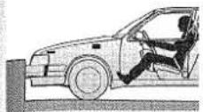
Start of collision.
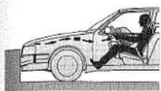
The sensor has registered the decrease in speed and sends a signal to a gas generator, via the control module, which inflates the airbag.

The airbag reaches the driver.
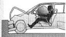
The airbag is completely inflated.
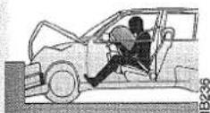
The steering column is crushed and the airbag starts to empty.
When the system is activated at the instant of a collision, the airbag incorporated in the steering wheel is inflated. The airbag will be inflated in the event of a severe frontal collision but will not activated by a minor head-on, rear-end or side collision or by the car rolling over.
WARNING
• Even though the car is equipped with a Supplementary Restraint System, seat belts must be worn by all the occupants.
• Note that since the airbag inflates and deflates extremely rapidly, it affords no protection in the event of a second collision occurring during the same accident.
- When driving, you should adopt a position with your entire back resting against the seat backrest and not sit hunched over the steering wheel. Otherwise, if the airbag is activated, you could be thrown forcibly against the backrest and sustain injury.
- Never attach any objects to the steering wheel as they could injure your face when the airbag is inflated. This also applies to objects, such as a pipe, in the mouth when driving.
- The gas that fills the airbag when it is set of is very hot. In certain circumstances the hot gas may cause burns on the arms as the airbag empties.
- If the warning lamp starts flashing or fails to go out when the car is being driven, the car should be taken immediately to an authorized Saab garage for checking. If the SRS warning lamp lights up or starts flashing, it could mean that the system would not be activated in the event of a collision.
The system should be checked in accordance with the service programme.
Front passenger airbag
As optional equipment, the car can be equipped with an airbag on the front-seat passenger's side. The system is the same as on the driver's side and it is connected to and monitored by the same SRS warning lamp. The airbag is located behind a cover on the dashboard. In a collision, both systems are activated even if the passenger seat is not occupied.
Disconnection of the airbag on the passenger's side.
Should you want to have the passenger airbag disconnected, always take the car to an authorized Saab garage.
WARNING
- Child seats should always be fitted to the rear seat. Otherwise the child could be injured by the airbag in a collision.
• Children younger than age 13 or shorter than 140 cm should occupy the back seat. - Children should not stand in front of the front passenger seat as they could be seriously injured by the airbag in a collision.
- Do not place any objects on the dash or in front of the seat as they could injure the car occupants in a collision or interfere with the operation of the airbag. Also make sure that no accessories are mounted on the instrument panel.
WARNING
No modifications affecting the steering wheel or the electrical system should be made to cars fitted with a Supplementary Restraint System. Both battery cables and the SRS electronic unit must be disconnected before any welding work is commenced. Following this, wait at least 20 minutes before starting on the actual work. The electronic unit must be removed from the car before quick-drying after painting.
Airbags and seat-belt pretensioners must be activated before the car is scrapped or when system components are removed for scrapping. Airbags and seat-belt pretensioners that have been activated in a collision must be replaced.
Work involving the replacement or scrapping of airbags or seat-belt pretensioners must be carried out by an authorized Saab garage.
Check the system as laid out in the Service Programme.
Common questions about airbag
Do you need to use a seatbelt in cars equipped with an airbag?
Yes. The airbag is only a compliment to the car's ordinary safety system. An airbag is only activated by heavy front-on collisions. It does not give any protection during minor collisions, side-on collisions, rear-end collisions or rollovers.
The seatbelt prevents the occupants of the car being thrown against each other and sustaining injury.
During a front-on collision, the seat belt also helps you meet the airbag in the right way, that is to say directly forward. If you hit the airbag at an angle, it provides much less protection.
The airbag offers no protection if another collision occurs immediately afterwards at the scene of the same accident. For this reason, always keep your seat belt fastened.
Does the detonation of the explosive charge make a loud noise?
The detonation makes a short loud noise. Most people who have experienced this do not remember the noise of the explosion, but rather the noise from the actual collision.
Can one use a child seat in the front seat if the car has an airbag in the passenger position?
No. The airbag is filled with such power and speed that the child seat would be thrown violently backwards, causing the child to incur serious injury.
Is the dust/smoke released dangerous?
Most people who have been in the car with bad or no ventilation for several minutes get only slight eye or throat irritation.
People who suffer from asthma may have an attack and should act as recommended by their doctor. They should then seek medical advice.
If possible, avoid getting the dust on the skin as it may cause irritation.
What should I do if the SRS lamp comes on?
The SRS system's diagnostic function has detected a fault. Drive to an authorized Saab garage as soon as possible.
WARNING
As the dust may, in certain cases, contain traces of detergent-like substances, the following precautions should always be taken:
- Skin which has come into contact with the dust should be washed with water and mild soap as soon as possible
• If the eyes are irritated, rinse with water
Child safety
The safety of children in the car is just as important as that of adults.
For maximum safety when travelling in the car, children should be restrained in some way. The form of restraint used must be adapted to the size of the child. Before fitting any kind of safety seat, harness, booster cushion, etc., you should first consult your Saab dealer. For market Australia, see also page 129.
Make sure you are familiar with the law and other regulations dealing with the fitting of child seats and how children should be seated in the car.
Your Saab dealer stocks child safety seats that are approved by Saab Automobile AB. If a child safety seat from a different manufacturer is used, make certain that it can be fitted correctly in accordance with the manufacturer's instructions.
For child safety seats requiring underneath anchorage straps there are four securing lugs under the front passenger seat to provide the best possible means of mounting.
WARNING
• Children should always be restrained in some way when travelling in the car.
- In cars equipped with an airbag on the front passenger's side, no child seat of any type should be fitted to the passenger seat. In the event of a collision the child could be injured by the airbag. For this reason, the passenger seat has no mounting lugs or colour markings for a child seat.
- Child seats fitted to the front passenger seat in cars not equipped with an airbag on the passenger's side must not be secured to the legroom adjustment control.
In an accident, the seat may move and have a detrimental effect on the anchorage of the child restraint.
For a child safety seat which is approved for rearward-facing installation on the rear seat, the place recommended for it is in the centre seating position. In such case, the child seat should be secured using the two rear mounting lugs under the driver's and front-seat passenger's seats.
Mounting lugs for a child seat with underneath anchorage straps.
NOTE! Mounting lugs at the front are not fitted in cars equipped with an airbag on the passenger's side

natural_image
Interior view of a car seat assembly with arrows indicating movement or force (no text or symbols)
Child seat mounting lugs (electrically adjustable front seat).
NOTE! There are no front colour markings on cars equipped with an airbag for front passenger
Always read the manufacturer's installation instructions supplied with the seat before fitting a child safety seat in the car.
In cars with electrically adjustable front seats there are four light-blue colour markings on the seat frame where child safety seats are to be anchored.
WARNING
- When a child safety seat designed for children weighing 0-18 kg is fitted facing rearwards on the front passenger seat, make sure that the backrest of the child seat rests against the dashboard. Carefully follow the installation instructions supplied with the child safety seat.
- When a child safety seat designed for children weighing 0-10 kg is fitted on the front passenger seat, the passenger seat should be in its rearmost position.
- It is just as important to ensure that the straps on the child seat are properly tightened. They must on no account be left slack. The child seat should be fitted as securely as possible to provide optimum protection for the child.
Saab child safety seats
Your Saab dealer stocks specially-adapted child safety seats for your car. They are approved by Saab Automobile AB and designed to provide the same degree of protection in the car as for adults. They are also comfortable and easy to use.
Child safety seats are available in two different versions, depending on the weight of the child: 0-18 kg and 15-36 kg.
For children age 0-9 months using the smaller child safety seat there is an accessory which improves the support given to the child. Ask your Saab dealer for details.
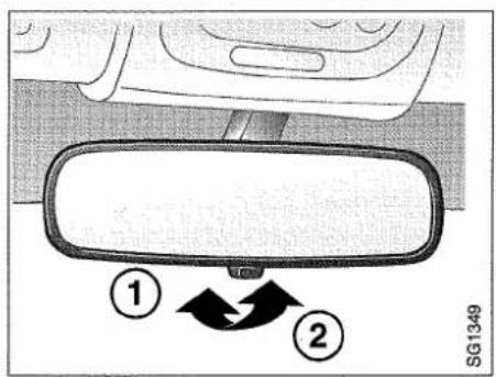
Rear-view mirror
1 Normal position
2 Deflected (anti-dazzle) position

natural_image
Mechanical assembly diagram showing a belt buckle with a black arrow indicating a specific part (no text or symbols present)Locking arm

natural_image
Diagram of a car intake tray with two buttons and a handle, no text or symbols presentDoor mirror switches
Rear-view mirrors
The interior rearview mirror is of anti-dazzle type and can be deflected by means of the lever under the mirror. Adjust the mirror with the lever in the normal position.
The door mirrors are anti-glare treated and the one on the driver's side is of the wide-angle type.
If subjected to excessive force, the mirrors will fold back. The mirrors can also be parked in this position. Carefully fold the mirror backwards until it engages the catch. To release the mirror, press it back and push in the catch.
The control for the door mirrors is located on the driver door.
The front switch for adjusting the mirrors can be moved in four directions. The rear switch is used to select the mirror to be adjusted.
Up = left
Down = right
Centre position = off
The door mirrors are electrically heated.
They are connected using the switch for the heated rear windscreen.

Switches, centre console
1 Control, sunroof
2 Control, electric windows
3 Control for switching off electric windows in rear doors
Electric windows
Opening:
Press the window symbol on the button.
The button has a second position for automatic opening. When the button is pressed beyond the first position, the window opens completely.
Automatic opening can be interrupted by quickly lifting the symbol side of the button.
Closing:
Lift the symbol side of the button.
Closing stops when the window is completely closed or when the button is released.
Child-proofing, rear electric windows (ON/OFF)
Using the ON/OFF button you can choose if the rear windows can be operated with the extra buttons in the rear doors.
In the "ON" position, the rear windows can be operated using the extra buttons in each rear door.
In the "OFF" position they can only be operated using the buttons in the centre console.
Door switches are also provided for operation of the rear windows, but these can be rendered inoperative by a switch on the centre console (marked ON/OFF) to prevent children playing with them.
WARNING
Always remove the key from the ignition when leaving the car to prevent anyone being injured by the electric windows or sunroof due to children playing etc.
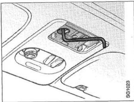
natural_image
Interior view of a car dashboard with airbags and a central connector (no text or symbols visible)Manual operation of sunroof
Sunroof
The sunroof is operated by the ROOF switch on the centre console. The sunroof can be opened fully or partially. As soon as the switch is released, the sunroof is locked in position.
1 To open the sunroof from the completely closed position, do as follows:
• To open - push the switch back
• To close - push the switch forwards
2 It is also possible to open the rear edge of the sunroof from the closed position (ventilation position):
• To open - push the switch forwards
• To close - push the switch back
You must however release the switch between each position to change between the two functions.
There is also a manually retractable sun shade over the glass sunroof.
When the sunroof has reached its end position, it can be opened a few centimetres further by pressing the button again.
But the button will then have to be pressed twice to close the sunroof.
A manual winder for emergency operation of the sunroof (e.g. in the event of an electrical fault) is stored inside the cover on the overhead switch panel. Insert the short end of the crank into the hexagonal hole.
Turn counter-clockwise to close the sun-roof.
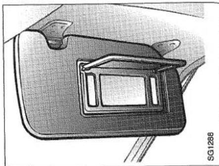
natural_image
Close-up of a car rear compartment showing the door and seat area (no text or symbols visible)Illuminated make-up mirrors
Illuminated make-up mirrors
Illuminated vanity mirrors are fitted on the rear of the sun visors. The light comes on when the mirror cover is raised. The sun visor must be fitted in both its brackets.
Ashtrays
The car is fitted with two ashtrays. One is in the dashboard and the other at the back of the centre console between the front seats. A cigarette lighter is provided beside the front ashtray. The cigarette lighter socket can also be used as an electric outlet for a mobile telephone or other equipment.
WARNING
The maximum current output from the cigarette lighter socket is 10 A.
The front ashtray is incorporated in the modular radio console. This system allows the owner to choose his own arrangement of the ashtray, radio, etc. in the three compartments.

natural_image
Diagram of a refrigerator interior showing internal compartments and storage shelves (no text or symbols)Front ashtray
To remove the front ashtray from its housing, first depress the catch and then withdraw the ashtray.

natural_image
Top-down view of a car backrest with visible door and seat, no text or symbols presentRear ashtray
To remove the rear ashtray, make sure it is fully open and then press down and pull it forward.
To refit the ashtray, engage the two springs in the corresponding lugs, press down on the ashtray and push it back in.
Audio equipment
Cables for the radio, aerial and speakers have already been run in the car. The cables are accessible behind the radio console, the speaker grilles on the fascia and the trim on both sides of the luggage compartment.
WARNING
• The radiated field in the cabin can dangerous to health
- The radiated field can cause interference in the car's electrical system
Mobile telephones and communications radio equipment without a separate external aerial radiate electromagnetic radio waves which are reflected inside the car. Saab therefore recommends always connecting your mobile telephone/communications radio to an external aerial.
An external aerial will also improve transmitting and receiving conditions as well as giving your equipment a longer range.
WARNING
- Bear in mind that using a mobile telephone while driving may take your attention away from the road, which increases the risk of an accident occurring.
- It is advisable to stop at a suitable place when using the telephone.
Glove compartment
WARNING
The glove box should be kept closed while you are driving. The lid could otherwise cause injury in a collision.
Additional storage space for oddments is provided at the front of the front seats and in the centre console on the passenger side.
Glove compartment (cars without airbag on the passenger side)
1 To unlock
2 To lock
3 To open the glove compartment

flowchart
graph TD
    A["①"] --> B["②"]
    B --> C["③"]
    C --> D["④"]
    D --> E["⑤"]
    E --> F["⑥"]
    style A fill:#f9f,stroke:#333
    style B fill:#ccf,stroke:#333
    style C fill:#cfc,stroke:#333
    style D fill:#fcc,stroke:#333
    style E fill:#cff,stroke:#333
    style F fill:#ffc,stroke:#333
Can holder
In cars equipped with can holders, there is a detachable insert in the storage compartment between the front seats. This insert has two recesses for cans/mugs and a storage space for compact discs etc. There are also can holders in the rear seat armrest.
natural_image
Technical drawing of a mechanical component with two circular holes and a curved base (no text or symbols)Can holder in rear seat armrest
Can holder in centre console

natural_image
Cross-sectional diagram of a mechanical assembly with three cylindrical components (no text or labels)
natural_image
Illustration of a sedan with open trunk and roof, showing structural components (no text or symbols)Doors, locks and luggage compartment
Doors and locks.... 60
Luggage compartment...... 61
Bonnet 64
Emergency opening of fuel filler cap.... 64
Anti-theft alarm 65
Doors and locks
The central locking system is operated by the locks in both front doors. The central locking system locks and unlocks doors and fuel filler cap.
The central locking system can also be operated from inside the car by means of a switch on the centre console. However, it cannot be operated by the locking buttons on the doors, which only lock and unlock their own door.
If you want to leave the car with the doors open, they should still be closed by such an amount that the courtesy lighting goes out. This will avoid running the battery flat.
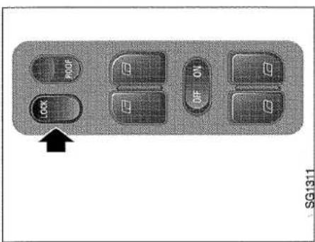
Central locking switch
Driver's door lock
1 To lock
2 To unlock
Child safety lock
1 Engaged
2 Disengaged


If you want to leave the doors wide open, remove the fuses for the interior lighting and electrically adjustable seats (fuse Nos. 16, 25 and 26).
The rear doors are fitted with child safety locks which are engaged and disengaged by a catch incorporated in the door lock. When the child safety lock is engaged, the door can be opened only from the outside.
WARNING
Locking the doors when driving reduces the risk of:
- passengers, especially children, opening doors and falling out.
- intruders getting into the car when slowing or stopping
- injury due to doors opening in an accident.
Note however that in the case of an accident, locked doors can make assistance from the outside more difficult.
To prevent injuries occurring due to careless or inadvertent operation of electrically adjustable seats, never leave children alone in the car.

natural_image
Interior view of a car showing the door, seatbelt, and directional arrow (no text or symbols)Switch for luggage compartment door
Tailgate lock

Luggage compartment
WARNING
Never place heavy objects on the parcel shelf as they could be thrown forwards and cause injury to the car occupants if the car is braked suddenly or involved in a collision.
The tailgate is not included in the central locking system. Unlock it by means of the switch on the driver's door or with the key. It is always locked when closed.
The parcel shelf is split into two sections. The rear section can be folded up to facilitate loading. The parcel shelf should be removed when the backrest and seat cushion
Removing the head restraint

natural_image
Diagram of a curved mechanical component with an arrow pointing to a small feature, labeled 'SG1021' (no text or symbols on the diagram itself)
natural_image
Mechanical component diagram showing a curved housing with a key inserted, no visible text or symbolsStowing the head restraint after removal
are folded forward. Otherwise, in the event of a collision, it might be thrown forward and cause injury. The parcel shelf can also be removed completely by lifting the rear section to free the pins from the holes and sliding the shelf out through the luggage compartment door. To increase the cargo space, the rear seat may be folded forward. Note that the head restraint must be removed before the backrest is folded forward. Release the catch and lift off the head restraint. Hang the head restraint on the pin in the top anchorage for the backrest.
With the narrower section folded forward, two people can occupy the rear seat and long narrow objects can be carried in the luggage compartment.

natural_image
Medical illustration showing a patient's bed with two pressure clips and three arrows pointing to the pressure point (no text or symbols present)Straps for seat cushions

natural_image
Medical illustration showing a surgical instrument inserted into tissue with an arrow indicating the insertion point (no text or symbols present)Backrest catch
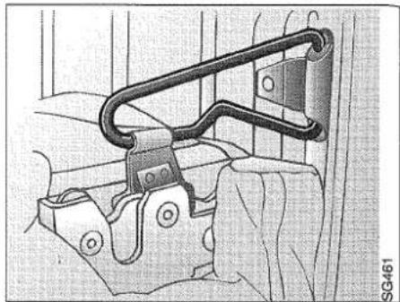
natural_image
Mechanical assembly diagram showing a clamp bracket and mounting bracket (no text or symbols)Catch for backrest folded forward
With the wider section folded forward, there is room for one rear-seat passenger and long, wider items of cargo.
To release the seat-cushion catch, pull the strap between the cushion and backrest forward and upwards.
Tip the cushion forward so that it stands on edge behind the front seats.
Release the backrest catch and fold the backrest forward. Press the backrest down so that the clip clears the top of it and secure the backrest. It is also important to press the backrest down when folding the clip back.
Lugs for securing load

natural_image
Top-down view of a car backrest with two black arrows pointing to the side panel (no text or symbols)WARNING
Lay heavy luggage flat on the floor close to the rear seat backrest. Then place smaller and lighter suitcases on top.
Whenever carrying a heavy or bulky load in the luggage compartment, always secure it to the four lugs provided for this purpose.
This reduces the risk of luggage being thrown forward in the event of sudden braking or a collision. In order to maintain the car's normal driving characteristics, its maximum load capacity must not be exceeded, see page 116.
Make sure that the seat and backrest cushions are locked in position when they have been folded back.
Tools
The tool box is stowed away at the right-hand side of the luggage compartment and can be easily removed for use outside the car.
The screwdriver handle has a "button" for removing rivets.
The spare wheel, jack and jack handle, and warning triangle are stored under a panel in the luggage compartment floor.
The hinged panel may be secured in the upright position by means of a rubber loop under the right-hand side of the parcel shelf.
Tool box
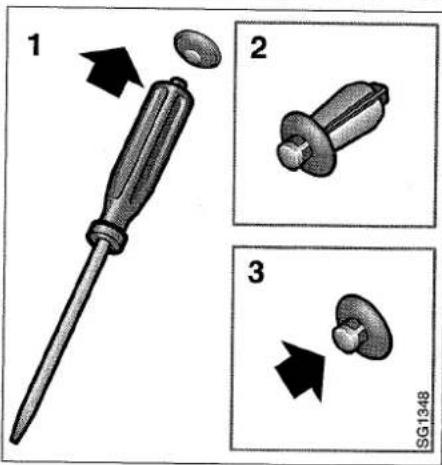
Removal/fitting of rivets using the "button" on the screwdriver handle.

natural_image
Technical illustration of a mechanical device with an open lid and internal components (no text or symbols)Bonnet
The bonnet release handle is located on the left-hand side, underneath the instrument panel. To open the bonnet:
1 Pull the handle.
2 The leading edge of the bonnet will then spring up, providing access to the safety catch.
3 Push the catch upwards and lift the bon-net.
To close the bonnet, release it from a height of about 20 cm (8 in). Do not push down on the bonnet.

natural_image
Medical illustration showing a surgical procedure with an arrow indicating direction (no text or symbols present)Bonnet release handle
Emergency opening of the fuel filler flap
If the central locking system should fail to release the fuel-filler flap, first check fuse 16. If the fuse is intact or a new fuse also blows, the flap will have to be unlocked manually.
Behind the tool kit on the right-hand side of the luggage compartment is a cord which is attached to the locking bar of the fuel filler cap flap. Pull this cord until it stops. The filler cap flap can then be opened.
Bonnet switch

natural_image
Mechanical component with a black arrow pointing to a handle, shown against a textured background (no text or symbols)Cord for emergency opening of fuel filler flap
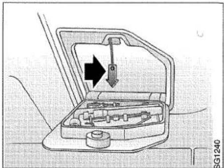
natural_image
Diagram of a car intake manifold with internal components and directional arrows indicating movement (no text or symbols)
Remote control for Anti-theft alarm
1 Button for activating/deactivating alarm
2 Button for unlocking the boot
Anti-theft alarm
Certain models have factory-fitted theft alarm.
The theft alarm is activated/deactivated using a remote control. On cars with Pacific specification, the alarm can also be activated/deactivated with the key in the driver door.
The car is supplied with two remote controls and can have an additional two. Contact your Saab dealer.
The alarm reception antenna is located beside the rear-view mirror. When the theft alarm is tripped, it is not possible to start the car as certain essential components are disconnected. This function is called three circuit breaking.
All doors as well as the bonnet and tailgate are monitored by switches. A glass breakage sensor sests off the alarm if any of the windows is broken.
The alarm is activated ten seconds after the car has been locked using the remote control. The hazard flashers flash once. During these ten seconds (delay time), doors, hood and tailgate can be opened without tripping the alarm.
Doors, locks and luggage compartment
During the delay time, the LED lights for ten seconds and then flashes every other second as long as the alarm is activated.
Note that the delay period does not start until the delayed interior lighting has gone out (approx. 15 seconds).
If any door, the hood or the tailgate is open, or if there is an electrical fault in the alarm control module when the car is locked using the remote control, the LED flashes once every second for 10 seconds to indicate that there is a fault.
Glass break sensor
The theft alarm is equipped with a glass break sensor to monitor the car windows. The glass break sensor is located in the center interior lighting.
In order to avoid false alarms when for example children or animals are left in the car, the glass break sensor should be disconnected. Disconnection is achieved by pressing the small button beside the glass break sensor after the ignition has been placed in the OFF position, but before the car is locked and the alarm activated. The LED flashes once a second for 10 seconds.
Doors
The alarm cannot be activated if the driver door is open. If any of the other doors is open or is opened during the delay period and is not closed before the delay period has expired, that door is excluded from the alarm.
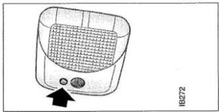
natural_image
Illustration of a portable electric cooker with a mesh grille and control buttons (no text or symbols)Button for disconnecting glass break sensor
When the door is then closed, a new delay period starts for that door and at the end of the delay, the door is once again included in the alarm.
When the door is closed, the LED lights for 10 seconds and then returns to flashing every other second.
Hood
If the hood is open or is opened during the delay period and is not closed before the delay period has expired, the hood is excluded from the alarm.
If the hood is closed, a new delay period begins for the hood and the hood is included in the alarm after this delay period.
When the hood is closed, the LED lights for 10 seconds and then goes back to flashing every other second.
Tailgate
If the tailgate is open or is opened during the delay period and is not closed before the delay period has expired, the tailgate is excluded from the alarm.
If the tailgate is then closed, a new delay period starts and the LED lights for 10 seconds and then returns to flashing every other second.
The tailgate can always be unlocked after the delay period has expired using the right-hand button on the remote control.
The other doors and the hood remain alarmed.
Signals when the alarm is tripped
During a theft attempt, the alarm sounds if the tailgate, hood or any of the doors is opened. The glass break sensor trips the alarm if any of the windows is broken.
The alarm is also tripped if there is an attempt to connect or by-pass the ignition switch.
The following signals are given when the alarm is tripped:
- All hazard flashers flash for 5 minutes.
- A sound signal is emitted for 30 seconds. If the alarm is deactivated during this time, the signals cease.
Flashing and sound signals can vary between markets due to legal and insurance requirements. See next page for a more detailed description of operation.
IMPORTANT
- The alarm may be deactivated and the car unlocked if the left-hand button is accidentally pressed when the car is within range.
- When locking using the remote control in extreme cold, check that the car is properly locked. The lock buttons in the door should go down.
Quick guide, light-emitting diode
| Situation | LED indication | |
| 1 | Activation (delay period) | Lit for 10 seconds |
| 2 | Alarm activated (after delay period) | 1 flash every other second |
| 3 | Deactivation | Lit for 1 second |
| 4 | Alarm not activated | off |
| 5 | Door, hood or tailgate open/opened during delay period | 1 flash/second for 10 seconds |
| 6 | Unlocking tailgate | 1 flash/second for 10 seconds |
| 7 | Closing of door, hood or tailgate after situation 5 or 6 above | Lit for 10 seconds |
| 8 | Only when the engine control module is disconnected (VSS feature) | Double flash every second |
| 9 | Fault in alarm system | Flashing instead of constant light during delay period |
| 10 | Disconnection of glass break sensor | 1 flash/second for 10 seconds |
| Activation | The hazard flashers flash once (0.5 s). The horn sounds once. On 9000 cars with Pacific specification, the alarm can also be activated/deactivated with the key in the driver door. |
| Deactivation | The hazard flashers flash three times. (3 x 0.5 s). If the alarm has been tripped by a theft attempt, the hazard lamps flash five times. (5 x 0.5 s). The horn sounds twice. The LED lights for one second. On 9000 cars with Pacific specification, the alarm can also be activated/deactivated with the key in the driver door. |
| Deactivating the tailgate | The hazard flashers light for two seconds. The horn sounds 3 times. |
| The alarm goes off | The hazard flashers flash for 5 minutes. The horn sounds for 30 seconds. To switch off the alarm when it has been set off, it is deactivated in the normal way (left-hand button). |
| Glass break sensor | The glass break sensor senses if one of the car's windows is broken and then activates the alarm. The glass break sensor can be manually disconnected by pressing the button next to the sensor's microphone before the theft alarm is activated. The disconnection of the glass break sensor is cancelled the next time the alarm is deactivated. |
| Remote control | The range of the remote control is approx. 8 meters. In favorable conditions, the range can be significantly further. Left-hand button: activating/deactivating the theft alarm. Right-hand button: deactivating and unlocking tailgate only. If a remote control is lost, the new remote control must be programmed together with the remaining remote control to adapt it to your car's unique theft alarm code. Contact an authorized Saab workshop. |
| Batteries | The remote control has two batteries which normally last for about two years. When the range of the remote control begins to lessen, the batteries must be changed. In order to avoid loss of function, it is recommended that the batteries are changed every year. After changing the batteries, depress the left-hand button five times in succession with the remote control directed at the car so that the theft alarm will recognize the signals from the remote control.If the remote control has been exposed to very low temperatures, it may malfunction. Warm the remote control in your hand for a few minutes.If the remote control does not work, even if the battery is good, the code signal may be out of phase. With the remote control directed towards the car, press the left-hand button five times in succession. |
| Battery positive voltage | If battery positive voltage is lost due to e.g. flat battery when the theft alarm is activated, the theft alarm is rendered unserviceable. When battery positive voltage returns to normal, the theft alarm will be activated in the same way as it was before the loss of voltage. |
Due to different national laws/requirements, the functions of the theft alarm may be different in different countries. Find out what national laws/requirements are in force. Some of the theft alarm functions can be reprogrammed. Contact your Saab dealer to find out about the possibilities.

natural_image
Illustration of a car driving on a road with two people visible, no text or symbols present.Starting and driving
Ignition switch and steering lock.... 70
Starting the engine.... 70
Running in.... 73
Gear changing 74
Cruise control 77
Braking 78
Economical motoring...... 79
Driving in winter weather..... 81
Driving in hot weather...... 82
Towing a trailer or caravan.. 82
Driving with the compact spare wheel fitted 85
Driving with a roof-rack load 85
Driving with the luggage compartment door open .... 85
Towing the car 86
Ignition switch and steering lock
The ignition switch has the following positions, turning the key clockwise from the locking position.
LOCK - Locking position
The locking position is obtained by turning the key anti-clockwise as far as it will go. This is the only position in which the key can be removed. The parking lights, hazard warning lights and interior lighting all work in this position.
Ignition switch

WARNING
- Do not remove the key from the ignition switch until the car has come to a complete halt as the steering column lock will then be activated and the car cannot be steered. When the engine has stopped, servo assistance for steering and brakes is no longer available.
• Always remove the ignition key if children are left behind in the car.
• Always apply the handbrake before removing the ignition key from the ignition switch.
OFF-position
The steering lock is not activated.
ON-position
The entire electrical system is operative. Never leave the key in the drive position unless the engine is running. Turn the key to the locking position and remove it.
Check-mode position
A check-mode position is provided between the ON and starting positions to enable the driver to check that the warning and indicator lights are working and that the pictogram lights up.
ST - Starting position
This operates the starter motor. When the key is released it will automatically return to the ON position. The car is equipped with a starter interlock device, which means that if the engine fails to start, the key must be returned to the LOCK position before it can be turned to the starting position again.
Starting the engine
WARNING
When starting the car inside the garage, make sure that the garage doors are open to allow the poisonous carbon monoxide to escape.
A leaking exhaust system also causes a risk of carbon monoxide poisoning.
The starter motor should not be run for more than 15 seconds at a time. Wait 20-30 seconds before running the starter motor again to give the battery time to recover.
Avoid racing the engine or putting a heavy load on it while it is cold. Drive off as soon as the oil warning light has been extinguished to enable the engine to reach its normal running temperature as soon as possible.
If the engine stops a few seconds after it has started, the anti-theft alarm's VSS system has been activated. Cancel it by pressing the remote control's left-hand button.
Starting the engine
The engine has an automatic choke and should be started as follows:
1 Depress the clutch pedal (man. gear-box). Do not touch the accelerator pedal.
2 Start the engine and let the ignition key spring back as soon as the engine is running (in very cold weather it may be necessary to keep the starter motor running for up to 15 seconds).
N.B. The engine of a car with automatic transmission can be started only when the selector lever is in the P or N position. Let the engine idle for around 10 seconds. Do not accelerate fully until the engine has run for at least 2 or 3 minutes.
N.B. The engine has hydraulic cam followers (which operate the valves) and these are completely service-free. The valve clearances are set accurately at the factory and will not require further adjustment.
In certain conditions, the hydraulic cam followers may emit a ticking noise that can be heard inside the car. This is most likely immediately after starting, before the oil pressure has reached its normal level.
It is also possible for air to enter the lubricating system when the oil or oil filter is changed or if the car has been left standing for a prolonged period. In this case, the ticking noise may be heard for as long as 15 minutes, but this is normal and does not indicate any malfunction.
However, do not exceed 3000 r/min until the noise has disappeared.
Each time the engine is switched off, the spark plugs are cleaned automatically.
Important points to note when driving the Saab 9000 Turbo
1 Starting and driving
- Never accelerate at full throttle before the reading on the temperature gauge is normal (N). If the needle on the pressure gauge repeatedly enters the red zone, a loss of engine power may be experienced owing to the safety cut-out system limiting the charging pressure. If this happens, take the car to an authorized Saab workshop without delay.
- Under certain atmospheric conditions, the needle may briefly enter the broken red zone, but this is normal and does not indicate a malfunction.
- A safety cut-out function (fuel shut-off) prevents the engine speed exceeding approximately 6,000 r/min.
2 Stopping the engine
- Do not rev the engine immediately before switching it off, but switch it off only when it is idling. This is to ensure that the turbo compressor is not run unnecessarily without adequate oil pressure.
3 Automatic Performance Control (APC)
- The system is optimized for 95 octane RON. One of the advantages of the APC system is that the engine can be run on petrol with a lower octane rating, although not lower than 91 RON,
without harm. For optimum performance, however, the recommended 95 octane RON grade of fuel should be used.
- The APC system adjusts the boost supplied by the turbo to suit the knocking/ pinking tendencies of the engine. Brief spells of knocking in the engine are perfectly normal. These may occur when a heavy load is put on the engine at about 3000 r/min and the extent of the knocking will depend on the grade of fuel being used.
- Isolated instances of knocking are more likely when low-octane fuel is being used. This controlled form of knocking followed by a reduction in the charging pressure merely indicates that the APC system is working normally, and is perfectly safe for the engine.
• However, if constant knocking occurs every time a load is put on the engine, this indicates a malfunction in the system and the car should be taken to an authorized Saab workshop.
Important considerations for cars with catalytic converter
IMPORTANT
Use only unleaded petrol. Use of lead-ed petrol will damage the catalyst and oxygen sensor and drastically reduce the performance of the device.
The catalytic converter is an exhaust emission control device incorporated in the exhaust system. Its active component is a honeycomb insert, the cells of which have their walls coated with an alloy of noble metals.
To ensure that the catalytic converter functions properly and to avoid damage to the active constituents of the catalyst, the following points must be observed:
• Always keep the car properly serviced in accordance with the service programme. This applies particularly to the fuel and ignition systems.
• Always be alert to any misfiring of the engine (engine not running on all cylinders), any loss of power or any symptom of reduced performance. At the first sign of anything being wrong, reduce speed and take the car to an authorized Saab workshop as soon as possible.
- If the car is difficult to start (in severe cold or if the battery is flat) the car can be bump started (manuals only) or started with the use of jump leads from another battery (see the section on starting assistance). However, as soon as the engine has started, it is important that it runs on all four cylinders. If not, let the engine idle for a maximum of five minutes to give it time to run smoothly. If, after this period, the engine still misfires, get in touch with an authorized Saab workshop.
- Do not park on dry gras or other combustible material, as there is a risk of the hot catalytic converter causing a fire.
• NEVER drive off if the engine is misfiring!
- If the car is being bump started and the engine is already at about normal temperature, the engine must run on all four cylinders immediately after starting. If after a bump-starting attempt the engine fails to start immediately, do not attempt to start it again by bump starting.
Failure to follow these directions can result in damage to the catalytic converter and associated components and may represent a breach of the warranty conditions.
Oxygen sensor-controlled ignition system
1 Oxygen sensor (Lambda sensor)
2 Catalytic converter

Running in
Pistons, cylinder walls and bearings need time to bed in, to obtain uniform, wear-resistant surfaces.
If a new engine is driven too hard, this gradual process of wearing in will not be possible and the life of the engine will be shortened.
During the first 1200 miles (2000 km) do not exceed 5000 r/min.
During the first 1800 miles (3000 km) never drive the car at full throttle other than momentarily.
Running-in of new brake pads
The running-in period for new brake pads is around 90 miles (150 km) of city driving or 300 miles (500 km) of highway motoring.
To extend the service life, avoid hard braking during this period.
Refuelling
Always make sure that you fill up with the right grade of fuel.
The fuel filler cap is located in the rear right wing.
Insert the fuel pump nozzle past the flange in the filler pipe and rest its first position marking (ring, "pimples" or the first turn of the spring) against the flange. Do not lift the nozzle while filling up is in progress.
IMPORTANT
Do not fill fuel all the way up the filler pipe - the petrol must be allowed room for expansion.
The fuel tank holds 66 litres.
Screw on the filler cap until you hear a click.
The best way of avoiding condensation in the fuel tank (and consequent risk of malfunctioning) is to keep the tank fairly full at all times.
In cold weather it may be advisable to add methylated spirits or denatured alcohol a few times to eliminate any condensate that may have formed.
WARNING
- Never use petrol for any other purpose than as fuel for the car.
- Petrol is highly inflammable and can cause severe burns. Never use a naked flame in the vicinity of petrol. Never smoke when filling up with petrol.
Gear changing
Manual transmission
The gear positions are marked on the gear lever. Before reverse gear can be engaged, the release ring underneath the gear lever knob must be lifted.
When changing gear, fully depress the clutch pedal and then release it smoothly. It is inadvisable to drive with one hand resting on the gear lever as this can increase the wear on the gearbox. When changing from fifth to fourth gear, do not press the gear lever sideways to avoid engaging second gear inadvertently, with over-revving and possible damage to the engine as a result.
When engaging reverse gear, make sure that the car is at a standstill and that your foot is off the accelerator. Move the gear lever firmly to the right in neutral before engaging reverse.
The table shows the road speeds at which you should change up for maximum fuel economy.
| Gear changing | Road speed |
| 1 - 2 | 15 mph (25 km/h) |
| 2 - 3 | 25 mph (40 km/h) |
| 3 - 4 | 40 mph (65 km/h) |
| 4 - 5 | 45 mph (75 km/h) |
Gear positions and gear lever
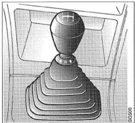
natural_image
Technical illustration of a mechanical gear shift lever inside a vehicle gear assembly (no text or symbols)Automatic transmission
WARNING
• Always keep your foot on the brake to keep the car from rolling when you select a drive position.
An illuminated dial with symbols that indicate the gear positions is located on the cowling around the base of the selector lever.
P = Park
R = Reverse
N = Neutral
D = 1st - 4th gear
3 = 1st - 3rd gear
2 = 1st - 2rd gear
1 = 1st gear only
forward speed
WARNING
Do not select P, R or N while the car is moving, especially not at high speed. This could cause accidents or damage to the gearbox if a driving position is selected again.
Positions of selector lever
The engine should be idling and the car standing still when the selector lever is moved from one position to another. Accelerating the engine while moving the selector lever can cause abnormal wear of the transmission.
Do not rest your hand on the selector lever while driving, since this may cause increased wear of the transmission.
IMPORTANT
Always wait a few seconds after selecting a gear before you accelerate, to give the gear time to engage.
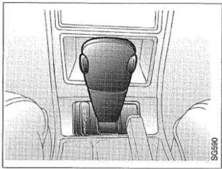
natural_image
Interior view of a car showing a person's seatbelt with hands adjusting the seat (no text or symbols visible)Selector lever
The selector lever is blocked in certain positions. The button on the lever must be pressed in before the lever can be moved. The selector lever is blocked between the following positions:
D → 3
N → R
R → P
P → R
3 → 2
P
The P position may be selected only when the car is standing still. The selector lever and transmission are blocked. The engine can be started.
R
The R position can be selected only when the car is standing still. The button on the selector lever must be pressed.
Wait for a few seconds before accelerating, to make sure that reverse gear has engaged.
N
In the N position, the engine is not connected to the transmission. The engine can be started. The handbrake should be applied to prevent the car from rolling on an incline. To avoid unnecessary increases in engine and transmission temperatures, position N should also be selected when the car is stationary for longer periods (such as in a traffic jam). Select position D when you are waiting for a traffic light. Do not shift to position N at higher speeds. The transmission may be damaged when the selector lever is returned to the drive position.
D
Position D should be used for ordinary driving. The car starts in first gear and then shifts up or down automatically between gears 2, 3 and 4. The moment at which shifting takes place depends on the position of the accelerator pedal and the speed of the car.
3
In this position, fourth gear is blocked. The car starts in first gear and then shifts automatically between second and third. Position 3 is recommended for driving on winding roads and in dense city traffic. If you shift from position D to position 3, the transmission will immediately downshift to third gear, causing hard overrun braking. The selector lever should not be moved to this position at speeds above 80 mph (130 km/h).
2
This position is advisable for mountain driving. The engine power can be used better, and the braking effect of the engine is improved. The transmission automatically shifts between first and second gears. The third and fourth gears are blocked. If you shift from position D or 3 to position 2, the downshift from third to second will only take place at a pre-programmed road speed, to prevent engine overspeed.
1
This position should be selected for ascending or descending very steep hills. As well as providing maximum engine braking on steep descents, continual gear changing that could cause the transmission fluid to overheat is also avoided.
Depending on which gear the car is in at the time, moving the selector lever from position D to 1 will cause the car to change down through the gears: if it is in top, it will change down immediately to third gear, followed by a change to second gear when the speed has dropped to about 45 mph (70 km/h) and finally to first gear at 20 mph (30 km/h). The selector lever must not be moved to this position at speeds above 80 mph (130 km/h).
Manual selection is also inadvisable when the roads are icy. With the selector lever in this position, the transmission cannot shift up to a higher gear.
Kick-down
When the accelerator pedal is pressed down to the floor - to the kick-down position - the transmission will shift down one gear at a given road speed to achieve the best acceleration, such as on overtaking.
The transmission will shift up one gear only if the engine speed is high, or if you ease off the accelerator pedal.
Cruise control
WARNING
Do not use the cruise control system on wet and/or slippery roads, in dense traffic or on winding roads. Set the switch to the OFF position if the system is not to be used. Cruise control may be inadvertently operated if the switch is left in the ON position.
Some varianus are equipped with the Cruise Control system.
The system is operated by a switch with positions having the following functions: OFF, TIP (temporary decrease in speed),
Cruise control switches

natural_image
Interior view of an airplane cabin showing seatbelt, air vent, and control panel (no text or symbols visible)ON and RES/- (resume) as well as a switch marked SET/+ (setting the desired speed). The CRUISE indicator on the combined instrument is illuminated in the ON position and goes out in the OFF or TIP position.
To select the required speed
Set the switch to ON. Accelerate to the desired speed (lowest speed: 25 mph or 40 km/h) and then press SET/+.
To increase the selected speed
Accelerate to the desired speed and then press the SET/+ switch. You can also increase the speed by means of the SET/+ button. Speed increases in steps of 1.6 km/h as long as the button is held down.
Temporary increase in speed
The system allows you to increase speed temporarily, for instance to accelerate for overtaking.
When the accelerator is released, the system will then revert to the preselected speed.
Reduction in speed
The cruise control system is always cancelled by operation of the brake or clutch pedal. A smoother reduction in speed is obtained by moving the switch to position TIP.
Starting and driving
Resume
You can return to the previously selected speed by briefly holding the switch in the RES/- position.
Speed can also be reduced by means of the RES/- button. Speed is reduced in steps of 1.6 km/h as long as the button is held down.
Disengaging the system
The cruise control system will be disengaged (switched off):
- if either the brake pedal or clutch pedal is depressed
- if the switch is moved to TIP
- if the switch is moved to OFF
- when the engine is switched off
Braking
When driving in alpine country and similar conditions, to avoid the risk of the brakes overheating on long descents, always use the braking effect of the engine by driving in a low gear (in automatics, selector lever in position 1 or 2).
In high-speed motoring, the life of the brakes can be increased by avoiding braking over long stretches. Instead, brake more firmly over a shorter period of time.
ABS braking - indication that the system is in operation

WARNING
It is good practice to try your brakes periodically while driving but particularly so if you have been driving through snow, slush or deep puddles or fords; if the brakes are wet, their efficiency may be drastically reduced until they dry out.
The car has power-assisted brakes and it should be remembered that the servo unit operates only when the engine is running. About four times as much pressure on the brake pedal will be required to apply the brakes if the engine is switched off, e.g. when the car is on tow. The pedal will feel hard and lacking in response.
When driving in heavy rain or through deep puddles, or when the car is washed, the brakes will get wet. One result of this is that a certain deterioration in braking power will be noticed when the brakes are applied. To minimize this, dry out the brake discs by braking lightly from time to time until full braking efficiency is restored.
This should also be done after the car has been washed and in extremely damp weather.
We advise against using light alloy wheels in wintertime as the components of the brake system will then be more exposed to corrosive slush splashed up on salt-treated roads.
Anti-lock brakes (ABS)
WARNING
No ABS system can counteract the laws of nature. Do not use the safety of the ABS system to increase speed.
In order to achieve as short a stopping distance as possible with better handling on dry, wet or slippery road surfaces, the brake pedal should always be fully depressed.
The anti-lock braking system (ABS) then automatically regulates braking pressure to each wheel brake. Braking pressure is reduced just before the wheel locks and then increases again to the point where it is about to lock. This adjustment of braking
ABS braking - steering away from danger
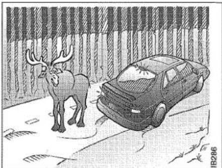
natural_image
Cartoon illustration of a deer and a parked car on pavement, no text or symbols presentpressure takes place up to 12 times per second.
ABS brakes do not reduce stopping distance on gravel and snow/ice, but as the wheel never lock, a certain steering capacity is retained.
When the ABS system is in operation, a pumping is felt in the brake pedal and a ticking sound can be heard. Keep the brake pedal fully depressed (it cannot be pressed too hard) and steer.
Never release the brake pedal until the car is stationary or the danger has passed.
If the road surface is slippery, the ABS is activated when the brake pedal is lightly depressed. This means that by testing the brakes, the driver can get an idea of the quality of the road surface and adapt his driving to it.
Economical motoring
To keep fuel consumption down and to minimize wear, the car must be driven smoothly and gently, and be serviced regularly.
- Avoid hard acceleration and racing the engine (recommended speeds for changing gear are given under 'Gear changing').
- Frequent gear changing (e.g. town driving), short trips when the engine is cold, driving with a roof rack or trailer attached and running on studded snow tyres all increase fuel consumption.
Conditions affecting fuel consumption
Fuel consumption is greatly affected by the general driving conditions and the style of driving, the weather, the standard of the road, the condition of the car, the speed at which it is driven, etc.
Running-in
During the running-in period of 3000-4000 miles (5000-7000 km), the fuel consumption may be higher than what is normal.
Weather conditions
Fuel consumption may be as much as 10% better in summer than in winter. Fuel consumption is higher in cold weather owing to the longer time it takes for the engine to reach normal temperature and for the transmission and wheel bearings to warm up. Fuel economy is also affected by the distance driven: short trips no longer than 3-5 miles (5-8 km) do not give the engine sufficient time to reach its normal running temperature. Strong winds can also affect fuel consumption. Read the graph as follows:
Graph showing the increased fuel consumption at different outdoor temperatures on cold starting as against starting with the engine at the normal temperature.

line
| Distance (km) | -28°C (-4°F) (%) | 0°C (32°F) (%) | +20°C (58°F) (%) | |---|---|---|---| | 0 | 200 | 190 | 70 | | 2 | 160 | 140 | 50 | | 4 | 120 | 100 | 30 | | 6 | 80 | 70 | 20 | | 8 | 60 | 50 | 15 | | 10 | 50 | 40 | 10 | | 12 | 45 | 35 | 8 | | 14 | 40 | 30 | 6 | | 16 | 35 | 25 | 5 |If the fuel consumption for the car with the engine at normal temperature is 28 mpg, then the actual fuel consumption after the car has travelled 3 miles (5 km) after starting from cold will be 23.5 mpg at an ambient temperature of 20°C (68°F) - an increase of 20%; 17.7 mpg at ±0°C (32°F) - an increase of 60%; and 14 mpg at an ambient temperature of -20°C (-4°F) - an increase of 100%.
When starting from cold, the distance travelled by the car and the temperature outside greatly affect fuel consumption, as shown in the graph. For instance, if you use the car predominantly for short trips (3-5 miles), the average fuel consumption may be 60-80% higher than normal.
Driving technique
Driving at high speed and frequent acceleration, braking and gear changing all increase fuel consumption, whereas smooth driving will reduce it. Since engine revolutions are higher in the low gears at a given road speed, frequent or prolonged driving in low gears will increase fuel consumption.
For this reason, always change up to a higher gear as soon as the traffic conditions allow and drive in high gear for as long as possible.
Practical trials on the roads have demonstrated that substantial savings in fuel consumption can be made if these tips are followed.
Road conditions
Wet roads increase fuel consumption, as do gravel roads and driving in hilly country (the amount of fuel saved travelling downhill is less than the additional amount required for driving uphill).
Car condition
The general condition of the car is of great importance to fuel economy. For economical motoring, pay particular attention to the following:
- Make sure that the car is serviced regularly in accordance with the service programme.
- Make sure that the tyres are correctly inflated; if the tyres are soft their rolling resistance will be higher and fuel consumption will be increased. Refer to the 'Technical data' section for correct tyre pressures.
- A roof rack reduces the aerodynamic efficiency of the car and thus increases fuel consumption. Remove the roof rack when not in use.
- Towing a caravan or trailer greatly increases fuel consumption.
Driving in winter weather
Before driving off in cold weather, check that the wiper blades have not become frozen to the glass.
Brush away any snow from the air intake for the heating system and, in extremely cold weather, apply suitable lubricant (molybdenum disulphide oil) to the door lock to prevent its freezing. If the lock has frozen, take care not to break the key when trying to unlock it. Heat the key first or apply some de-icing agent to it.
Now and again when refuelling in the winter, add fuel additives to prevent any condensation in the fuel tank from freezing and disrupting the fuel supply. To keep down the risk of condensation, keep the fuel tank full.
When the outside temperature is below freezing point and the car is parked outdoors, fuel additives like "carburettor spirits" (methylated spirits or denatured alcohol) will have no effect as any water in the fuel tank will freeze to ice. Condensation is caused by temperature changes, either in the ambient air or as a result of the car being parked alternately in a heated garage and outdoors.
It is particularly important when the roads are slippery that the brakes and tyres are in good condition.
The car is fitted with tyres which provide exceptional grip on both wet and dry roads, although this has been achieved at the
expense of somewhat reduced grip on snow and ice. For driving in these conditions, we therefore recommend that special winter tyres be fitted.
These provide the best grip on icy roads, especially if fitted with studs.
If winter tyres are to be used, the same type of tyre must be fitted to all four wheels. Your local Saab dealer will be pleased to advise you of suitable tyres.
If your car has automatic transmission and you intend to use snow chains, the car should first be equipped with the winter tyres recommended in the 'Technical data' section.
If the car gets into a front-wheel skid, disengage the transmission by depressing the clutch (so that the wheels are freewheeling) and steer the front wheels in the direction you wish to go. At all costs, avoid touching the brakes. To control a rear-wheel skid, steer into the skid (i.e. steer in the direction the rear of the car is moving).
WARNING
Do not exceed 30 mph (50 km/h) when using snow chains.
When using snow chains, inspect the links for wear at regular intervals.
Snow chains may cause deterioration of the road behaviour.
Do not use snow chains on the rear wheels.
Driving in hot weather
• Always check the level of the coolant before starting a journey.
- Drive in as high a gear as possible, even uphill (this keeps engine revs down and helps to prevent overheating). On cars with automatic transmission, avoid using the kick-down position.
- At the end of the journey, let the engine run at idling speed for two or three minutes.
If the temperature gauge pointer enters the red zone:
1 Stop the car. If the car is equipped with ACC, this system must be turned off but do not switch off the engine. Do not take off the expansion tank filler cap even if the tank is empty. If the temperature continues to rise when the engine is idling, switch off the engine.
2 Wait until the temperature gauge indicates normal temperature (around the middle of the scale) before turning off the engine. If the coolant needs to be topped up, carefully unscrew the expansion tank filler cap and add equal parts of water and Saab anti-freeze.
3 Have the car inspected by an authorized Saab garage.
Towing a trailer or caravan
Towing attachment
Towing attachments suitable for towing loads up to a maximum of 1,800 kg are available as optional accessories.
A socket for connection of the trailer's electrical system is located underneath the floor trim adjacent to the left-hand rear light cluster.
Saab recommendations:
- Use a genuine Saab towing attachment. These are designed and tested for and by Saab.
- Ask a Saab dealer for advice on a suitable towing attachment for your car.
- For maximum strength and reliability, bumper reinforcement brackets should be fitted.
When towing a trailer, the headlight beam-length adjustment switch should be set to Headlights, see page 15.
IMPORTANT
A genuine Saab towing attachment should always be used as other towing attachments could damage the car's electrical system.
Consult your Saab dealer for advice and instructions on fitting the electrical connections for towing a trailer.
Mounting points for a genuine Saab towing attachment.


natural_image
Diagram showing a car pulling a vehicle on a road with a triangular warning symbol (no text or labels)<10% max 1800kg (CS)/ 1600kg (CD)

natural_image
Side view of a car being towed from a vehicle, showing engine release (no text or symbols)
10 - 12% max 1300kg

natural_image
Diagram showing a car being pulled off from a vehicle, with no visible text or symbols
12 - 15% max 1000kg

natural_image
Illustration of a car being stopped by a van with a cross symbol (no text or labels)15%
Trailer (or caravan) weight
Maximum recommended trailer weight for different gradients, see illustration.
Make sure you are familiar with the law regarding speed limits for towing, maximum trailer weights and trailer braking requirements and also any special driving licence provisions.
WARNING
A trailer should not be towed if gradients of 15% or more are likely to be encountered. This is because the load on the driven front wheels will be so low that they are likely to lose their traction and start spinning, making further driving impossible. The handbrake will not always be able to hold the car and trailer stationary, as the wheels may slip on the road surface.
Towing attachment load
The weight distribution of the trailer load makes a lot of difference to the handling properties of the car and trailer combination. On a single-axle trailer, whenever possible concentrate the load over the wheels and keep it as low as possible.
The load should be distributed such that the load on the towing attachment is between 50 and 75 kg (110-160 lb). Note that this load is part of the car's total load capacity and that the load in the boot may need to be reduced by a similar amount.
Starting and driving
Driving
When towing a trailer always make allowance for the altered handling characteristics of the car and the reduced braking effect. The trailer brakes, springs and dampers greatly influence these characteristics.
On cars with automatic transmission, select first gear on very steep uphill and downhill gradients.
On steep uphill gradients, engine cooling can be improved by setting the heater for maximum heating and running the ventilation fan at its highest speed or disconnecting the air conditioning system.
Instructions for detachable towing attachment
IMPORTANT
Make sure that the coupling stud (A) and the ball are always greased.
WARNING
Serious bodily injury and material damage could result if the instructions are not followed in the right order.
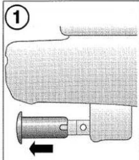


To fit
1 Remove the protection cover.
2 Turn the ball section's handle clockwise to the locked position.
3 Slide the ball section onto the coupling stud (A). Press the ball section to the locked position.
4 Check that the indicator pin (B) is in its inner position and that the handle is as shown.
To remove
1 Turn the handle clockwise to the locked position.
2 Pull the ball section off the coupling stud (A).
3 Fit the protective cover in place as shown.

Driving with the compact spare wheel fitted
Please observe the following when driving with the compact spare wheel (115/70 R16) fitted.
Do not drive any further than is necessary as the maximum life of the wheel is 2000 miles (approx. 3500 km). Change back to a standard wheel as soon as possible.
WARNING
Do not exceed 50 mph (80 km/h), as this may cause overheating of the tyre and deterioration of the road behaviour.
The tyre on the compact spare wheel should be inflated to a pressure of 4.2 bar (420 kPa).
Avoid driving too close to kerbs, as the ground clearance is lower when the spare wheel is fitted. Similarly, do not fit snow chains. The car must not be driven with more than one compact spare wheel. Do not fit a hub cap, as this would cover the warning text.
Spare tyre 175/70 R15 T
As an option, the car can be equipped with a larger spare wheel. The maximum speed for this wheel is 80 km/h as prescribed by law and the tyre pressure msut be 2.5 bar (250 kPa).
Driving with a roof-rack road
The maximum permitted load carried on the roof rack is 100 kg (220 lb).
Note that roof-rack loads are included in the car's carrying capacity. The roof-rack mountings must be robust and able to withstand high stresses and the load must be securely lashed. A roof rack designed specially for the car is available from your Saab dealer.
Do not exceed a road speed of 70 mph (110 km/h) when carrying long and/or heavy loads on the roof.
Roof rack mounting points

natural_image
Illustration of a hand gripping a coiled cable or wire (no text or symbols visible)Driving with the luggage compartment door open
Owing to the fact that driving with the luggage compartment door open enables exhaust fumes to be drawn into the car, this should be avoided whenever possible. However, if this is unavoidable, close all windows, and set the heating and ventilation to maximum ventilation on the highest defroster setting.
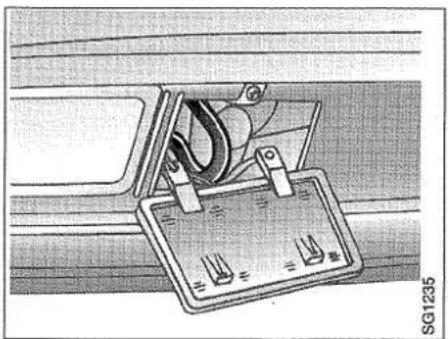
natural_image
Technical diagram of a mechanical device with attached components and mounting brackets (no visible text or symbols)Front tow-rope attachment eye
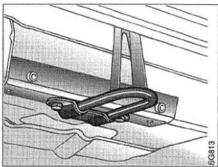
natural_image
Technical illustration of a mechanical clamp or bracket assembly (no text or symbols visible)Rear tow-rope attachment eye

natural_image
Technical diagram of a mechanical component with no visible text or symbolsFront towrope attachment eye (certain variants)
Towing
The car is equipped with towrope attachment eyes at the front and rear.
Some models have a special towing eye attachment stored in the spare wheel well under a panel in the luggage compartment. Open the cover in the spoiler and screw the towing eye attachment firmly in place.
Drive carefully and never exceed the speed limit for towing. Keep the tow rope taut. This is achieved by the driver of the towed vehicle braking carefully when necessary.
WARNING
- Never tow a car that is heavier than the towing car.
- Never allow anyone to sit in the towed car.
- Remember that the servo for the power-assisted brakes is inoperative when the engine is not running and the brake pedal will have to be pressed much harder than normal.
- The servo for the power steering is also inoperative when the engine is not running and the steering will be very heavy.
• Professional assistance should be called for if breakdown towing is required.
WARNING
Cars with a detachable front towrope attachment eye:
• Always make sure that the front tow-rope attachment eye is properly secured.
- The towrope attachment eye should only be used for towing the car on a road.
- The towrope attachment eye is not designed for towing the car if it has been wrecked in an accident.
When towing a car with automatic transmission:
a The gear selector lever must be in the N position.
b Fill the transmission with 2 extra litres of fluid, over and above the normal amount. Use Dexron II ATF.
c National regulations on towing speeds must be observed. If legal, the highest towing speed permitted is 30 mph (50 km/h). The longest towing distance permitted is 25-30 miles (40-50 km). If the car must be towed a longer distance, the front wheels must be raised from the ground.
d Before the car is driven again, check the transmission fluid level and adjust it to the prescribed level.
e The engine cannot be started by towing or pushing the car. It can be started as described in the section entitled "Boost starting using jump leads".
WARNING
Do not remove the key from the ignition switch as this activates the steering wheel lock and the car cannot be steered.
IMPORTANT
Since the handbrake acts on the rear wheels, make sure it is off when the car is towed with the front wheels raised off the ground.
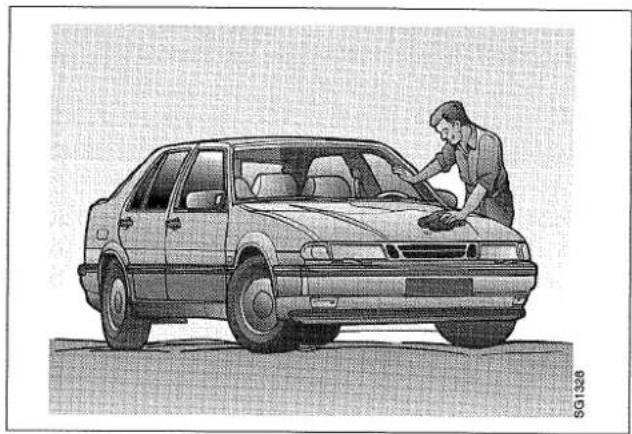
natural_image
Illustration of a man washing a car with a tool on the roof (no text or symbols)Car care and maintenance
Engine 90
Engine oil 91
Gearbox oil 92
Coolant.... 93
Brake/clutch fluid and brake pads 95
Steering system 96
Battery 96
Boost starting using jump leads 97
Alternator.... 98
Wipers and washers 98
Headlight alignment..... 100
Changing bulbs.... 100
Fuses 105
Wheels and tyres 106
Driving with the compact spare wheel fitted.... 109
Flat spots.... 109
Air conditioning (A/C)...... 109
Seat belts.... 110
Upholstery and trim...... 111
Textile carpeting.... 111
Engine compartment...... 111
Washing the car.... 112
Waxing and polishing ..... 112
Touching-up the paintwork 112
Anti-corrosion treatment ... 113
Service Programme...... 113
Motoring abroad 114

Engine compartment, Turbo models
1 Engine oil dipstick
2 Brake/clutch fluid reservoir
3 Electrical distribution box for ABS system
4 Battery
5 Washer fluid reservoir
6 Power distribution panel in engine compartment
7 Turbocharger
8 Ignition cartridge
9 Cooling system expansion tank
10 Fluid reservoir for power steering
Engine
All models have front-wheel drive and a transverse-mounted 2.0-litre or 2.3-litre engine. The engine is a water-cooled, four-cylinder, in-line engine with twin overhead camshafts and 16 valves. The cylinder head is inclined forward at an angle of 20^ . The engine is also equipped with an exhaust emission control system.
The engine is equipped with two counterbalance shafts which reduce engine vibration to a minimum.
The counterbalance shafts are chain driven and rotate at twice the crankshaft speed. They produce forces and moments that are opposed to those generated by the pistons and connecting rods, an effect occurring twice during each revolution of the engine.
Counterbalance shafts
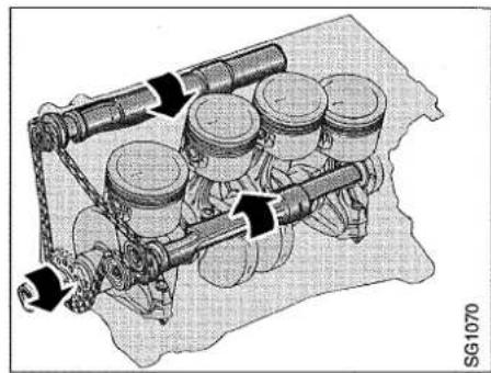
natural_image
Mechanical assembly diagram showing piston-cylinder linkage system with no visible text or symbolsThe result is that vibrations from the moving parts of the engine are counteracted, and undesirable engine noise is reduced.
The gearbox is at the right-hand end of the engine (viewed from the front) and forms an integral unit with the engine.
Engine oil
Check the oil level in the engine regularly. Make sure the car is on level ground and allow the engine to cool from normal temperature for between two and five minutes. Remove the dipstick, wipe it on a clean rag and then check the level.
The level must never be allowed to drop below the minimum mark on the dipstick, but nor should the level be topped up higher than the maximum mark as this may result in excessive oil consumption.
The distance between the maximum and minimum marks on the dipstick corresponds to approximately one litre (1.75 imp. pints).
Top up as necessary with oil of the recommended grade through the dipstick tube. Do not add oil if the level is higher than midway between the maximum and minimum marks on the dipstick. Make sure that the dipstick is screwed down tightly (finger-tight) after use.
The engine oil should be changed at the intervals specified in the service programme.

Oil filler cap with dipstick
More frequent oil changes may be necessary if the car is driven in any of the following cases:
- frequent and lengthy periods with the engine idling
• repeated stop-go driving - short distances in cold weather when the engine has no time to reach normal operating temperature.
If the car is driven under any of the above conditions, changing the oil at 10,000 km intervals is recommended.
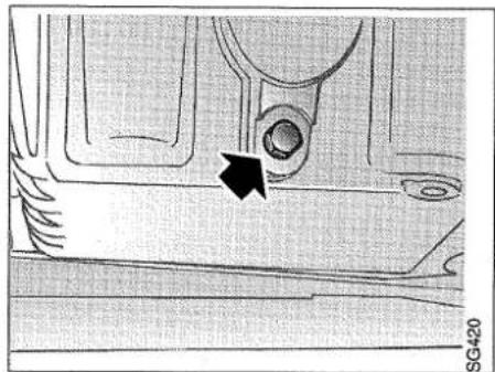
natural_image
Technical line drawing of a mechanical component with a black arrow pointing to a circular feature (no text or symbols)Drain plug
To change the oil, make sure that the engine is warm. Unscrew the drain plug in the bottom of the sump and leave the oil to drain into a suitable receptacle for at least ten minutes. Keep your hands away from the oil as it is likely to be hot.
Refer to the 'Technical Data' section for details of the recommended oil grade and quantity and, after filling, check the oil level on the dipstick as described above.
WARNING
Lengthy and repeated contact with engine oil may be harmful to the skin and a certain possibility of contracting cancer cannot be altogether ruled out.
Avoid getting oil in your skin as far as possible and wash it off meticulously with soap and water.
Do not touch the turbo system and/or manifold, which can become very hot after driving.
Do not spill oil on hot parts of the engine, as this can cause fire.
Gearbox oil
Manual gearbox
Check and top up as indicated in the service programme. The gearbox oil should not be changed.
Gear changing - automatic transmission
Check the fluid level in the transmission regularly, as follows:
1 Park the car on a level surface and apply the handbrake. When checking the fluid level, the transmission must be at operating temperature (around +176°F +80°C).
Dipstick for automatic transmission fluid
2 Set the selector lever to P or N and let the engine idle.
3 Wipe the dipstick with a lint-free cloth.
4 The transmission fluid dipstick has two sets of MIN and MAX marks. The fluid level should be between the upper MIN and MAX marks if the fluid is at operating temperature. Top up with fluid of the prescribed type as required. See the section entitled Technical Data.
5 The distance between the marks is equivalent to around 0.5 litres. Add fluid through the dipstick tube. If the ambient air temperature is low (below 32°F or ±0°C), the correct level may be in the lower section of the upper MIN/MAX scale, since the fluid will not reach +176°F.

natural_image
Mechanical assembly diagram showing a valve mechanism with no visible text or symbolsCoolant
The expansion tank is transparent to facilitate checking of the coolant level. The level should be between the MAX and MIN marks on the side of the tank. Top up as necessary with equal parts of water and Saab anti-freeze. After filling an empty expansion tank, run the engine to normal temperature and then top up again as required.
Expansion tank, coolant
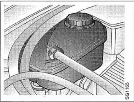
natural_image
Mechanical assembly diagram showing a car wheel and hoses (no text or symbols)Coolant
The cooling system is filled at the factory with a coolant containing 50% antifreeze and corrosion inhibitor. The mixture should never be weaker than this due to the risk of corrosion. A higher concentration is necessary in extremely severe cold-weather conditions.
For protection at -50^ (-58°F), a 60% concentration of anti-freeze will be required. The corrosion inhibiting properties of the coolant deteriorate in time, but genuine Saab (original) coolant should be used for year-round protection. The coolant should be changed as specified in the service programme. Use only "Saab coolant". Anti-freeze of other makes may require changing at more frequent intervals and may also be detrimental to the car.
N.B. When adding antifreeze to the coolant, mix it with water in the required proportions first. If neat antifreeze is added, the engine may still be damaged by frost as the antifreeze will not be distributed quickly enough throughout the cooling system until the thermostat has opened to allow full circulation.
WARNING
Take care when opening the bonnet if the engine is boiling. Never open the filler cap on the expansion tank while the engine is hot. Allow the engine to cool down before removing the cap.
The cooling system is pressurized. Always open the filler cap on the expansion tank carefully to release the pressure before removing the cap completely.
Changing the coolant
(normally carried out in connection with "Saab Original Service" at an authorized Saab garage)
1 If the engine is hot, open the filler cap on the expansion tank carefully to release the pressure in the system. Do not remove the filler cap.
2 Place a suitable receptacle under the radiator and unscrew the drain plug.
3 Remove the filler cap on the expansion tank.
4 After the system has been drained completely (after about two minutes) tighten the drain plug.
N.B. Finger-tight only.
5 Mix the anti-freeze solution with water to the required strength in a watering can or other suitable receptacle, using only Saab-approved anti-freeze.

natural_image
Mechanical assembly diagram showing a component being inserted into a housing (no text or symbols visible)Changing the coolant
6 Slowly fill the expansion tank with coolant. This will take a couple of minutes as the air must be allowed to escape.
7 Screw the expansion tank filler cap in place and warm up the engine. Fill up with coolant until the level is between the MAX and MIN marks on the tank.
8 Check the coolant level again in a few days and top up as necessary.

Radiator assembly
1 Fan for A/C condenser (certain markets)
2 A/C condenser (coolant/air)
3 Intercooler (air/air)
4 Ordinary engine radiator (coolant/air)
5 Radiator fan
Brake fluid and brake pads
Checking
The combined reservoir for brake and clutch fluid is transparent, to facilitate checking of the fluid level.
The level of the coolant should be between the MAX and MIN marks.
Top up as necessary with brake fluid of the recommended grade.
For topping up, use only fluid that has been stored in a closed container. Check that there are no leaks in the brake system.
In time, the brake fluid will absorb water and vapour may be formed. It is therefore vital that the brake fluid be changed at the intervals specified in the service programme.
This work should be done by an authorized Saab workshop.
Car care and maintenance

natural_image
Mechanical component diagram showing a valve assembly inside a vehicle's head (no text or symbols visible)Brake/clutch fluid reservoir
Since the footbrake and handbrake have automatic adjustment, it is not possible to detect, by signs of excessive pedal travel or lever movement, when the brake pads are worn and need replacement.
Thus, it is vital that the thickness of the linings be checked regularly as specified in the service programme.
The work of changing the brake pads and adjusting the handbrake cable must be carried out by an authorized workshop using genuine Saab brake pads.
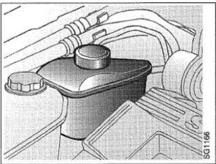
natural_image
Technical illustration of a mechanical component with no visible text or symbolsPower steering fluid reservoir
Steering system
The level of the fluid in the power steering reservoir must be checked regularly as specified in the service programme.
The reservoir has graduations for cold and hot fluid. When the engine is at normal running temperature, the fluid level should be between the HOT and COLD marks.
If the level is checked when the engine is cold, the level should be between the COLD and the ADD marks.
Use "Saab Power Steering Fluid 4634".
Never start the engine with the fluid reservoir filler cap off as the fluid might then gush out of the reservoir under pressure.
Battery
WARNING
The battery gives off hydrogen which, when mixed with the oxygen in the air, forms the highly explosive gas oxyhydrogen. Therefore, always avoid causing sparks or using a naked flame when working on or near the battery.
Since the battery contains corrosive sulphuric acid, always wear a face mask or protective goggles when carrying out any work involving the battery.
Should the acid come into contact with your eyes, skin or clothes, wash the affected areas immediately with plenty of water. In the event of it getting into your eyes, or if a large quantity of the acid gets on your skin, call a doctor without delay.
The car battery is sealed-for-life and under normal conditions will not require maintenance. Refer to the "Technical Data" section.
Check the charge of the battery at regular intervals and more frequently during the winter when the battery's capacity will be reduced by low temperatures. The check can be made by noting the voltage drop on starting the engine. See "Trip computer" on page 10.
As a basic guide, the voltage should not drop below approx. 11 V at an ambient temperature of +20°C (68°F) nor below approx. 10 V at -10°C (14°F).
The battery may also be checked by using a hydrometer to check the specific gravity of the electrolyte, which should be 1.28.
Battery
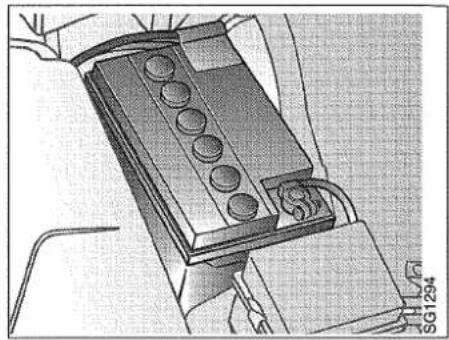
natural_image
Mechanical component with multiple circular holes, shown in a mechanical assembly (no visible text or symbols)If the car is used repeatedly for only short journeys during the winter, the battery may need extra charging - either by means of a battery charger or by taking the car for a longer run.
A car with standard equipment and a fully charged battery can stand unused for no more than 40 days and still have sufficient charge to start the engine. Optional equipment fitted, such as alarm, mobile telephone etc., can reduce this time to about 15 days.
Always make sure that you connect the red positive (+) lead to the positive (+) battery terminal and the blue negative (-) lead to the negative (-) battery terminal. Always disconnect the positive (+) battery lead before connecting a battery charger to boost the battery.
IMPORTANT
Never reverse the polarity of the battery. If the battery leads are connected to the wrong terminals or either of the battery or alternator leads is disconnected while the engine is running, the alternator may be irreparably damaged.
Boost starting using jump leads
To avoid arcing or flashover, jump leads for boost starting must be connected correctly.
1 Switch off the ignition and all power consumers (lights, rear window heater, etc.).
2 Switch off the engine in the donor car.
3 Start by connecting the positive terminal of the donor car battery to the positive (+) terminal of the flat battery. Next connect the negative (-) terminal of the donor car battery to the engine's lifting eyebolt, for example, of the faulty car, furthest away from the battery.
WARNING
Do not connect the negative (-) lead from the donor car to the faulty car battery because a spark could ignite the explosive gas in the battery.
4 Start the donor car and then start the engine in the faulty car. Let it run for a while before disconnecting the jump leads in the reverse order.
Boost starting using jump leads
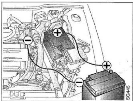
Alternator
The alternator is located to the left of the engine, adjacent to the false bulkhead panel. The alternator is driven by a multi-groove belt from the crankshaft pulley.
WARNING
Make sure that loose garments do not become caught in the drive belt when the engine is running.
Multi-groove belts last longer than conventional vee-belts and can also transmit a higher torque.
It is very important that the belt has the correct tension. The belt tension is maintained with an automatic tensioner.
See also page 7 "Charging warning light".
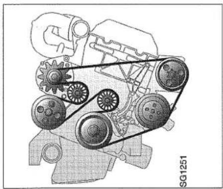
natural_image
Mechanical gear assembly diagram showing interconnected components (no text or labels)Drive belt (2.0 and 2.3 litre engines).
Wipers and washers
Regularly check and clean all wiper blades. Saab washer fluid is recommended for cleaning.
If the wiper is not functioning properly, clean the window with Saab washer fluid. This is especially important after an automatic car wash as they sometimes use wax treatments that coat the windscreen.
If the quality of the wipe is still unsatisfactory, change the wiper blades. The wiper blades should be changed if they show any signs of wear.
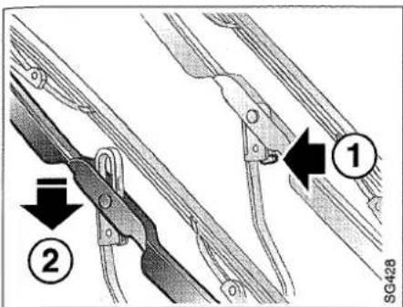
Changing wiper blades
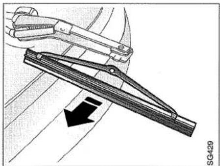
natural_image
Mechanical assembly diagram showing a lever mechanism with an arrow indicating motion (no text or symbols present)Removing the headlight wiper blade

natural_image
Mechanical component diagram showing a valve assembly with a black arrow indicating direction (no text or symbols present)Washer fluid reservoir
Changing the windscreen and rear window wiper blades
Lift the wiper arm off the windscreen.
1 Press in the catch
2 Move the wiper blade down the arm until it comes away from the arm. Detach the blade completely from the arm.
Changing the headlight wiper head
Lift the wiper arm away from the glass and detach the blade by holding the middle and pulling it away from the arm. To fit the new blade, slide the blade into the clips and press it firmly home.
Washers
The washer fluid reservoir holds 4 litres. The indicator light comes on when about 0.8 litres of fluid remains in the reservoir. About 0.1 litres of this amount is for the rear window washer. Top up with at least 50% "Saab Washer Fluid" and water to reduce the risk of freezing and obtain the optimum cleaning effect.
The washer nozzles are adjustable. Insert a pin or the like in the jet hole and swivel to the correct position.
The rear window washer nozzle is mounted on the right in the high-level brake light.
Headlamp alignment
WARNING
Switch off the engine before adjusting the headlamps to avoid getting your hands and fingers injured by rotating parts in the engine bay.
Adjustment of headlight alignment is carried out by means of two knobs at the back of each headlight unit, accessible from the engine bay. Adjustment requires the use of a screwdriver.
Headlight alignment
1 Lateral adjustment
2 Vertical adjustment

Changing bulbs
WARNING
Switch off the engine before changing any bulb to avoid getting your hands and fingers injured by rotating parts in the engine bay.
Changing the headlight bulb
1 Dipped beam bulb
2 Parking light bulb

Headlights, dipped beam and parking lights
IMPORTANT
Do not fit bulbs with a higher rating than 55W.
Always fit the same type (such as Long-life) when the bulbs need changing.
Unscrew the cover on the rear of the headlight. To unhook the spring clip holding the dipped-beam bulb, first press the clip forwards and then towards the middle. Take out the bulb and unplug the connector.
Insert the new bulb, without touching the glass envelope with your fingers. Fit it in the reflector, making sure that the lugs engage in the slots, and clamp it in place with the spring clip.
The parking light bulb is located beside the dipped beam bulb. Disconnect the leads and change the bulb.
Headlight, full beam
IMPORTANT
Do not fit bulbs with a higher rating than 55 W.
Always fit the same type (such as Long-life) when the bulbs need changing.
Open the plastic cover by pressing the tongue to the side and pulling it straight out. Remove the cover by first withdrawing its lower bracket and then its upper one. Disconnect the leads and unhook the spring clip.
Remove the bulb. Fit the new bulb, taking care not to touch the glass with your fingers. Make sure the bulb holder engages
Changing the full beam lamp

natural_image
Mechanical component diagram showing internal parts and a directional arrow (no text or symbols)with the slots in the reflector and secure it with the spring clip.
Front light clusters
Undo the retaining clamp. Carefully withdraw the light cluster. The bulb holder has a bayonet fitting. Grasp the two plastic tongues and twist the bulb holder anticlockwise.
Pull the bulb holder out of the fitting and change the bulb. Ensure that it is firmly located and makes good contact.
When refitting the light cluster, make sure that the peg engages with its hole in the body.
Front light cluster
1 Direction indicators
2 Retaining clamp
3 Peg
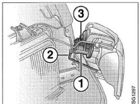
Rear light clusters
Open the access hatch in the trim. Squeeze together the two catches on either side of the lamp holder unit. Carefully withdraw the entire unit from the light fitting. Change the defective bulb.
Rear lights
1 Indicator
2 Tail light/brake light
3 Tail light
4 Rear fog light
5 Reversing lights
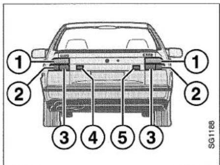
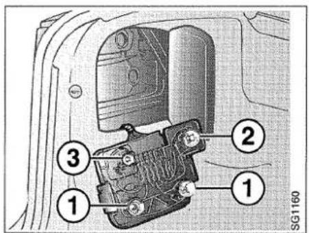
Rear light clusters
1 Indicator
2 Tail light/brake light
3 Tail light

natural_image
Illustration of a light bulb mounted on a wall-mounted switch next to a door, with no visible text or symbols.Changing the bulbs in the rear lights and rear fog light

natural_image
Interior view of a car showing the dashboard and seat area (no visible text or symbols)High-level brake light
High-level brake light
Undo the screws retaining the cover and lamp glass. Change the bulb.

natural_image
Technical illustration of a mechanical component with attached housing (no text or symbols)Side direction indicators
Side direction indicators
To change side direction indicators, push the glass forwards to release the rear end of the glass and change the bulb. When fitting the glass, make sure that the groove in the metal tongue engages the body sheet.
Door lights, number plate light and luggage compartment light
Unscrew the glass covering the bulb. Press back one of the spring contacts and remove the bulb.
Dome light
Remove the lamp glass from the lamp housing by releasing it at the rear edge. Fit a new bulb.
Cars with sunroof: Release the entire lamp housing by pulling down the front edge. Pull out the lamp housing and fit a new bulb.
Rear-view mirror light
Pull down and remove the glass and change the bulb.
Rear reading lights
Pull out the front of the fitting, prise back the plasticcatches to release the bulb holder, pull the bulb holder forward and change the bulb.
Seat belt warning light
Unscrew and remove the surround on the overhead switch panel.
Cars without sunroof: The screw is behind a plastic screw cap.
Cars with sunroof: The screw is behind the cover.
Change the bulb.
Other lights
If other bulbs need changing, we recommend that this be done by your Saab workshop.
1 | 7  |
2 | 8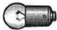  |
3 | 9 |
4 | 10 |
5  | 11 |
6  | SG1271 |
| No. | Watt | Base | |
| 1 | 55 | H1 | Headlight |
| 2 | 4 | Ba 9s | Parking lights |
| 3 | 1,2 | W 2x4.6d | Switch: front ashtray |
| 4 | 5 halogen | Rear reading light, reading light on overhead panel | |
| 5 | 21 | Ba 15s | Rear direction indicators; brake lights; reversing lights; rear fog light |
| 6 | 21/5 | BAY 15d | Tail light/brake light |
| 7 | PY 21 yellow | BAU 15s | Front direction indicators |
| 8 | 5 | Ba 15s | Tail light |
| 9 | 5 | SV 8.5 | Number plate illumination, rear-view mirror light, door lights, centre console light, seat belt warming light |
| 10 | 10 | SV 8.5 | Dome light, luggage compartment light |
| 11 | 5 | W 2.1x9.5d | Side direction indicators; high-level brake light |
Fuses
WARNING
To avoid the risk of fire and/or short circuits in the car's electrical system, the following should be observed:
- Before modifying or connecting any electrical equipment, contact your Saab garage as incorrect installation may cause damage or short circuits/fire in the car's electrical system.
- Never fit a fuse of higher amperage than the one that has blown.
- If the same fuse blows repeatedly, take the car to a garage and have its electrical system checked.
The fuses are housed on three power distribution panels: One inside the glove compartment, one at the front of the engine bay and one (for the ABS system) at the back of the engine bay.
In cars equipped with an airbag on the passenger side the main fuse box is located in the lower part of the instrument panel.

natural_image
Diagram of a car interior showing internal compartments and a control panel (no text or symbols)Power distribution panel

natural_image
Mechanical assembly diagram showing a component with mounting holes and a base plate (no text or symbols)Power distribution panel in engine compartment
Electrical distribution box for ABS system
Main fuse box (cars with an airbag on the passenger side)

natural_image
Technical illustration of a mechanical component with mounting holes and wiring (no text or symbols)
natural_image
Technical illustration of a car interior showing the door, handle, and seat (no text or symbols)A list of the fuses showing the components and circuits they protect is included in the 'Technical Data' section.
A special tool (together with spare fuses) for removing fuses is provided in the glove compartment. Push the tool onto the fuse and withdraw it.
If the wire in the fuse is broken, the fuse has blown. When replacing a fuse, make sure that a fuse of the correct rating (amperage) is used. The fuses are colour coded according to amperage and the rating is also marked on each fuse.
Sound fuse / Blown fuse
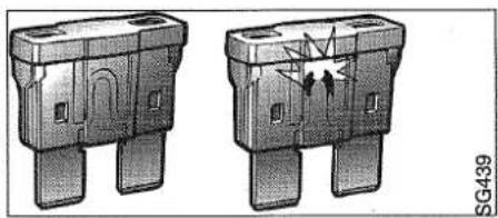
natural_image
Two identical 3D mechanical components with mounting holes and internal features, shown from different angles (no text or symbols visible)Wheels and tyres
Tyres
The tyres and wheels have been carefully designed to match the character of the car and to contribute significantly to its good roadholding characteristics. If you wish to equip your car with tyres or wheels of a different type than those with which the car was delivered, consult your Saab dealer beforehand about available alternatives.
Tyre designations
As an example, the designation 195/65 R 15 87H on a tyre means:
195 width of the tyre in mm
65 profile ratio between the height and width of the tyre, in per cent
R radial ply
15 wheel diameter: 15 inches
87 load code
H the tyre is approved for speeds up to a maximum of 130 km/h (210 km/h)
Other speed rating codes
Q tyre approved for 160 km/h max.
T tyre approved for 190 km/h max.
V tyre approved for 240 km/h max.
W tyre approved for 270 km/h max.
Z tyre approved for speeds above 240 km/h
Tyre pressures
The tyre pressures should be checked regularly. Inflate the tyres to the recommended pressures for the load to be carried and the normal cruising speed of the car (see the tyre pressure table in the Technical Data Section). The recommended pressures apply to cold tyres. Never reduce the pressure when the tyres are warm. If warm tyres are being checked, only increase the pressure. Tyres that are incorrectly inflated will wear much more quickly and also greatly reduce the roadholding capabilities of the car.
A leaking tyre valve can readily be changed. Simply unscrew the defective valve and screw in a new one.
N.B. Always remember to adjust the tyre pressures if the usual load or cruising speed is to be altered substantially.
Wear indicators
The tyres incorporate wear indicators in the form of smooth, treadless strips running across the width, which become visible when only 1.6 mm of the tread remains. As soon as the wear indicator becomes visible, the tyre should be replaced.
Make sure that you are familiar with national regulations on tread depth and what types of winter tyres are permitted.
Switching wheels
Due to front-wheel drive, the front tyres become worn faster than the rear ones. When replacing existing tyres with new ones, this should at least be done in pairs, so that the tyres on each axle are the same condition. When fitting one new pair of tyres, these should be fitted to the rear as the handling of the car (e.g. when braking/skidding) is better when the least worn tyres are at the rear. Do not switch sides when the existing rear wheels are moved forwards.
Wear indicators

Panel secured in raised position

natural_image
Close-up of a car interior showing a handle and seat, with no visible text or symbolsChanging the wheels
WARNING
- The jack is for emergency wheel changing and snow chain attachment only and not for regular maintenance repairs. For other work the car should be supported on axle stands.
- Never crawl under the car when it is supported by the jack alone.
• Take particular care when using the jack if the car is on a hill or cambered road surface. NOTE: use chocks as an extra safety precaution. - Place the chocks in front of and behind the wheel diagonally opposite the one to be changed.
- Switch on the hazard flashers when wheel changing at the roadside.
- Apply the handbrake and engage 1st gear or reverse on cars with a manual gearbox, or select position P on cars with automatic transmission.
- Never jack up the car with people inside.
-
Never start the engine when the car is jacked up.
• Make sure that the jack is positioned on firm and level ground. -
Stow the jack correctly in the place provided for it under the panel in the floor of the luggage compartment. Do not leave it loose in the luggage compartment as it could injure the car occupants in the event of a collision.
• The jack supplied should be used only with your Saab car. - We advise against using light alloy wheels in wintertime as the components of the brake system will then be more exposed to corrosive slush splashed up on salt-treated roads.
The spare wheel, warning triangle and jack with crank are stored beneath a panel in the luggage compartment floor. The raised panel can be hooked open by means of the rubber strap attached to the parcel shelf bracket on the right-hand side. The car tool kit is secured to a panel in the side trim on the right-hand side of the luggage compartment.

natural_image
Mechanical clamp device with spring mechanism and connecting rod (no text or symbols visible)Correct position of jack
To jack up the car, insert the jack in one of the jacking points underneath the sills (two on either side). If a trolley jack is used, this must be applied either to the reinforced subframe for the engine or under the reinforced member adjacent to the rear tow-rope eye.
IMPORTANT
Do not apply the jack to the rear axle
1 Apply the handbrake. Insert the jack. Wind the jack down and check that the flange at the top of the jack fits snugly against the sill and that the entire foot is in contact with the ground.
2 Remove the hub cap by carefully prising it off with a screwdriver.

natural_image
Diagram of a wheel with a central knob and two arrows pointing to the center, no text or symbols present.Removing the hub cap
Note that the wheel wrench can be used to release the clamp for the spare wheel. Slacken the wheel studs half a turn.
3 Wind the jack up until the wheel is clear of the ground. Undo the wheel studs and remove the wheel.
4 Fit the wheel and tighten the wheel bolts, making sure that wheel and bolts are correctly positioned.

Tightening sequence for wheel studs
5 Lower the car. Tighten the wheel studs in the sequence shown using the wheel wrench included in the car tool kit.
Tightening torque: 120 Nm
Never overtighten the studs by using a percussion nut tightener as it may not be possible to undo them using the car wheel wrench.
Note: when refitting the wheel cover after changing a wheel, make sure that the air valve fits in the wheel cover's aperture.
6 Retighten the studs after 20-50 miles. Tightening torque: 120 Nm
Compact spare wheel
The compact spare wheel (115/70 R16) is designed for ease of handling at the roadside when a wheel needs to be changed because of a puncture. The wheel should only be used in an emergency and, with the spare wheel fitted, the car should not be driven further than 2100 miles (3500 km).
WARNING
Do not exceed a speed of 50 mph (80 km/h) as this may cause overheating of the tyre and deterioration of the road behaviour.
The tyre pressure on the spare wheel should be 4.2 bar.
Place the wheel that has been removed inside the plastic bag provided.
Change back to the ordinary wheel as soon as possible.
Flat spots
All tyres become hot when driving, especially on long journeys or during hard driving. When the car is parked after this type of driving and the tyres cool, they may get a so-called flat spot. This means that the surface of the tyre against the ground becomes somewhat flattened which can lead to steering wheel vibration similar to tyre imbalance. The flat spot disappears when
thetyres warm up again after 20-25 km driving at out-of-town speeds.
Air conditioning (A/C)
IMPORTANT
- All repair and adjustment work on the A/C system must be carried out by an authorized Saab garage having the necessary personnel and equipment for such work.
- Special tools and a special purging procedure are required for R134a refrigerant.
- Never mix R134a and R12 refrigerants.
WARNING
- The A/C system is pressurized. Do not loosen or remove any connections in the A/C system.
- Escaping gas could cause blindness or other injury.
Fault diagnosis
If a malfunction should occur in the air conditioning system, you can carry out the following checks yourself. If the fault persists, take the car to an authorized Saab workshop.
IMPORTANT
When the air-conditioning system is running, condensate will form on the evaporator. When the car is parked, this condensate may drip off and form a small pool of water under the car.
Inadequate cooling capacity
a Check that the condenser (fitted forward of the radiator and intercooler) has not become clogged by dirt and insects.
b Check that the compressor drive belt is not slipping.
c Check the fuses for the fans and compressor.
Maintenance and servicing
- The car should be taken to an authorized Saab workshop once a year for servicing of the air conditioning system.
- Check the compressor drive belt at every regular service.
- The condenser and radiator must be kept clear of insects and other dirt. When washing the car, use the hose to spray the radiator and condenser to flush away any dirt and foreign bodies, spraying through the grille at the front of the car and from inside the engine compartment. Do not use high-pressure water. Do not use a hose when the engine is hot.
Never place a fine-mesh net or any other form of screening in front of the radiator as this will drastically reduce its cooling capacity.
Seat belts
WARNING
Seat belts and belt pretensioners that have been exposed to severe loads such as those occurring in a collision must always be changed, regardless of whether or not they are visibly damaged.
Never carry out any belt repairs yourself or attempt to modify the function of the belts.
Check periodically that the seat belts are working properly. A sharp tug on the strap should cause the inertia reel to lock. Check the floor anchorage points to ensure that they have not been weakened by corrosion. If the belt is worn or has any fraying edges, it should be replaced.
The belts must not come into contact with substances such as polishes, oil or chemicals. If the straps get dirty, wash them with soap and warm water or have them replaced.
Upholstery and trim
To remove fluff or hairs from the seat upholstery or headlining, use a moist, lint-free cloth or a special fluff-removing roller. Remove any dirty marks using a cloth moistened with lukewarm soapy water. When using a stain remover to remove dirty marks, always work from the outside towards the centre to avoid leaving a ring. However, if a dirty ring or a spot of dirt should remain, this can usually be removed using warm soapy water or water alone. Wet patches caused by spilt soft drink or thin oil must be wiped off immediately using an absorbent material, such as kitchen paper. Then treat the patch with stain remover. White spirit is recommended for removing grease or oil stains. Plastic trim may be washed with warm water and a synthetic detergent. A semi-stiff brush may also be used.
Cleaning and caring for leather upholstery
Leather upholstery should be treated principally to enhance the elegant appearance, but also to protect the surface. Wear and dirt may very well discolour leather, particularly the lighter shades. Although this does not affect the wear properties - a wear patina is often desirable on a leather surface - a surface which is too dirty may impair the visual quality.
The leather upholstery should be cleaned and reconditioned when the car is inspected in the spring and autumn (twice a year). Moisten a soft cloth in a mild soap solution. Carefully apply this damp (not wet) cloth to the leather with light, circular movements until the leather is clean. Repeat this procedure using clean water. Let the leather dry completely. Then apply Saab Leather Cleaner - a leather conditioner which can be purchased from authorized Saab dealers.
Apply the leather conditioner with the same circular movements as described above. Use a soft cloth. Let the leather conditioner dry and polish the leather with a soft, dry cloth. Follow the instructions given above. Do not use hot water, unknown abrasive polishes, solvents, sprays or soaps that may scratch the leather. This treatment will keep the leather upholstery clean and attractive for many years.
Textile carpeting
The textile carpet should be vacuum cleaned regularly. The carpet may also be cleaned using a brush or carpet shampoo applied with a sponge. Before using a vacuum cleaner, make sure that it is properly earthed.
Engine compartment
Clean inside the engine bay using an engine detergent and rinse with hot water. Cover the headlights and avoid spraying the radiator, throttle cable and other engine controls, the generator, ignition system and other electrical component, particularly if high-pressure equipment is used.
If using a high-pressure hose, the nozzle should be directed at 90° to the surface being washed. This is especially important where there are labels.
Do not use petrol as a cleaning agent or solvent when carrying out repairs or maintenance work. An environment-friendly degreasant is more suitable.
Washing the car
Wash the car frequently. When the car is new, wash the body by hand using cold water and a brush attachment on the end of a hose. During the first five or six months, before the paintwork has hardened properly, avoid automatic car washes. Thereafter use a car shampoo added to lukewarm water. Bird droppiogs should be washed off as soon as possible because they may cause discoloration which is difficult to remove by polishing.
Use a cloth moistened in white spirit to remove spots of asphalt or tar. Avoid using strong cleaning agents as these may dry out the paintwork. Do not use solvents to clean the front and rear light clusters as these are liable to cause crack formation in the lenses.
The underbody also needs washing regularly, and this should be done extra thoroughly at the end of winter. Clean the underbody thoroughly by hand if the car is usually washed in an automatic car wash without special facilities for underbody cleaning.
Never wash or allow the car to dry in the sun but wipe it dry with a leather immediately after washing to avoid smears and streaks.
Clean the window glass inside and out using a proprietary window cleaner. This is particularly important when the car is new, as the upholstery and trim may have a slight tendency to sweat at first.
IMPORTANT
Check that the brakes are in proper working order after the car has been washed. Wet brakediscs will give poorer braking performance.
Lower the electric aerials by switching off the radio before entering an automatic car wash.
Clean the aerial about once a month with a clean, dry cloth. NOTE: do not use oil or any silicone-based cleaning agent.
Fixed aerials must be removed.
Washing and polishing
A new car should not be waxed before three or four months. The bodywork will not need polishing before the paint has oxidized and become dull. Abrasive polishes containing a cutting agent should only be used in exceptional cases on a new car. Before waxing or polishing, make sure that the paintwork has been thoroughly cleaned.
Touching-up the paintwork
Damaged paintwork should be treated as soon as it is discovered. The sooner it is treated the less will be the risk of corrosion starting.
Damage to paintwork after the car has been involved in a collision is usually extensive and can only be properly restored by professionals.
However, you can deal yourself with chips in the paintwork caused by stones thrown up from the road as well as minor scratches. The necessary tools and materials, such as brushes, touch-up paint and primer, are available from your Saab dealer.
In the case of minor flaws in the paintwork, where the metal has not been exposed and an undamaged layer of paint remains, touch-up paint can usually be applied direct after any dirt has been scraped away with a knife-point.
If the metal has been exposed and corrosion has started, all surface rust must be scraped off using a knife-point. If possible, the entire damaged area should be scraped to the bare metal. The metal should then be primed with two thin coats of primer applied with a brush. The top coat should then be applied in several thin layers until the surface of the damaged area is level with the surrounding paintwork.
The primer and touch-up paint must both be stirred thoroughly before use. Allow each coat of paint to dry before applying the next coat.
Two-coat paint
As the name implies, two-coat paint is applied in two operations. The first coat - the base paint - contains the pigment - metal flakes and binder. The second coat consists of a clear varnish which provides the final gloss for the paintwork and protects the base paint from moisture and environmental pollutants.
To touch-up paintwork chipped by stones, proceed as follows: Thoroughly clean the area and then apply the primer, base paint and finally the clear varnish. To achieve the best finish, apply the primer in two or three coats.
Anti-corrosion treatment
The entire car is corrosion-protected at the factory in different stages with electrolytic paint, primer, a polyester-based protective coating against stones flung up by the wheels and thin penetrating anti-rust oil in cavities and body members.
Some metal bodywork parts are partly galvanized.
The anti-corrosion treatment on the underside of the car and inside the wheel arches is particularly exposed to wear and possible damage, the degree of which will obviously depend on driving conditions. Dirt and, more especially, salt thrown up from the road can then initiate corrosion.
It is therefore advisable to make a habit of hosing down the underbody and checking the anti-corrosion treatment. Even while the car is covered by the corrosion warranty, you are still responsible for having the maintained normally, which includes touching-up any damage.
After the underbody has been hosed clean and allowed to dry, apply viscous anti-corrosion oil to any worn or damaged areas, using a spray applicator or paintbrush. Even after the corrosion warranty has expired, it is in your own interest to maintain the anti-corrosion treatment and assure your car of long-term protection.
Seams in the body and doors are particularly vulnerable to the onset of external corrosion caused by dirt and road salt and on the inside by moisture not least condensate. Keep the seams clean and, at the first sign of corrosion, treat the affected area with a thin anti-corrosion oil by means of a spray applicator or brush. If necessary, consult your Saab workshop.
Service programme
Periodic service
Australia only: This vehicle conforms to the Australian Exhaust Emission Control. Regulations ADR37/00 applicable to 1993 new motor vehicles. Servicing of the emission control system should be carried out by an authorized Saab dealer.
Every car needs regular servicing and maintenance if it is to provide trouble-free motoring. A Service Programme has been drawn up for your car, and this includes specifications of work that should be carried out at given intervals. Service Book
contains the information about the Service programme.
The Warranty Conditions specify that the prescribed services and oil changes must be carried out at the stated intervals by an authorized Saab workshop.
IMPORTANT
To ensure that your car is properly serviced and to keep servicing costs to a minimum, the "Saab Original Service" programme includes preventive maintenance to avert possible malfunctions and to maintain a high standard of safety. The service also includes work necessary to ensure compliance with the relevant exhaust emission regulations.
Have your Service Book with you when you hand over your car for a service, and when collecting your car, make sure that all of the items specified in the programme have been carried out and that the Service Book has been stamped in the correct place.
A valid stamped Service Book is not only an assurance of reliability and motoring economy but also adds to the trade-in or second-hand value of the car.
The scope and content of the Service Programme may be changed from time to time but your authorized Saab workshop will always have up-to-date details of any changes affecting your car.
Motoring abroad
Before setting off on a long journey it is advisable to have your car checked over at an authorized Saab garage.
Obtain a few important items to take along on your journey, such as spare bulbs, wiper blades, fuses, a multigroove drive-belt, etc. You can check some points yourself beforehand:
• Make sure that the engine is in good condition.
- Check that no oil or petrol leaks out of the engine and gearbox.
- Inspect the multigroove drive-belt and change it if it shows signs of hard wear.
- Check the condition of the battery and its charge.
- Inspect the tread pattern and check the inflation pressures of the tyres, not forgetting the spare.
- Make sure that the maximum permitted speed for the vehicle's tyres is not exceeded in countries with no speed limit. For speed rating, see section headed "Wheels and tyres" on page 106.
- Check the brakes.
- Check all bulbs.
- Check the tool kit.
- Make sure there is a warning triangle in the car and that you are familiar with the law concerning its use in the countries you will be visiting.
- When driving from a country with left-hand traffic to a country with right-hand traffic or vice versa, cover over with black tape that part of the headlamps giving an asymmetric dipped beam. Otherwise you will dazzle oncoming traffic.
- Consult your Saab garage if you intend to drive in countries where unleaded petrol or petrol with a sufficiently high octane rating is not available. The garage must then make certain adjustments to the engine.
Taping headlamp glass for driving in countries with left-hand drive

natural_image
Two rectangular electronic components with internal circuitry and triangular cutouts, no visible text or symbols
natural_image
Illustration of various measurement tools including pressure gauge, ruler, analog multimeter, and probe (no text or symbols present)Technical data
General 116
Engine.... 118
Electrical system 120
Drive belts 120
9000 Audio System...... 123
Manual gearbox 124
Automatic transmission..... 124
Suspension 125
Brakes.... 125
Steering 125
Wheels and tyres 125
Car identification 126
General
| Overall lengthth, incl. bumpers ____ | 4761 m |
| Overall width (incl. door mirrors) ____ | 2000 mm |
| Overall height ____ | 1420 mm |
| Wheelbase ____ | 2672 mm |
| Ground clearance (car carrying 3 adults + 1 child with combined weight of 240 kg) ____ | 154-159 mm |
| Track between front wheels (5 1/2 J x 15) ____ | 1510 mm |
| Track between front wheels (6 J x 15) ____ | 1522 mm |
| Track between front wheels (6 1/2 J x 16) ____ | 1534 mm |
| Track between front wheels (7 J x 15) ____ | 1538 mm |
| Track between rear wheels (6 J x 15) ____ | 1480 mm |
| Track between rear wheels (6 1/2 J x 16) ____ | 1492 mm |
| Track between rear wheels (5 1/2 J x 15) ____ | 1504 mm |
| Track between rear wheels (7 J x 15) ____ | 1508 mm |
| Turning circle (measured kerb to kerb) ____ | 10.9 m |
| Turning circle (measured wall to wall) ____ | 11.9 m |
| Number of seats (incl. driver) ____ | 5 |
| Washer fluid reservoir capacity ____ | 4.1 litres |
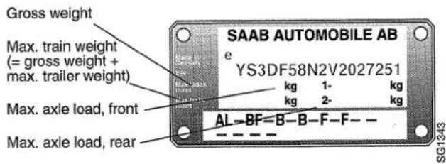
Permitted load (in addition to driver) = gross weight - kerb weight
Note that the maximum permitted axle load, front and rear, must not be exceeded.
The exact kerb weight (unladen weight + á 70 kg driver) and load capacity are set out in the registration documents.
Chassis number plate in engine compartment
Weight, ready for driving (includes full tank, washer fluid, tools and spare wheel) 1360-1505 kg
Gross weight 1920-1960 kg
Max. axle load Front ____ 1060 kg Rear ____ 980 kg
Weight distribution: Kerb weight, front/rear ____ 60/40 % Gross weight, front/rear ____ 50/50 %
Max. permitted load on roof ____ 100 kg
Max. permitted trailer weight Trailer with brakes ____ 1800 kg Trailer without brakes ____ 750 kg
Max. tow ball load 75 kg
Luggage compartment
| Volume (SAE) | |
| with parcel shelf | 448 dm ^3 |
| with rear seat folded | 1183 dm ^3 |
| Maximum permissible load in luggagecompartment:At curb weight with 4 passengers havingcombined weight of 280 kg ____ | 100 kg |
| Length of luggage compartment: | |
| with rear seat folded | 1670 mm |
| Rear seat upright | 1010 mm |
WARNING
Permitted gross weight and axle load must never be exceeded. Note that the installation of certain optional extras (e.g. towbar, CD changer) reduces the load capacity correspondingly.
When carrying a load, always make sure it is securely fastened. This is especially important if the car is used with the rear seat folded forward.
Engine
| Engine type | Saab Turbo Engine Oil or an oil which meets the requirements of API Service SG and CCMC G4 or G5. | |
| 2.0 and 2.3 litre engines | 4 cylinder, 4 stroke with 2 overhead camshafts and 16 valves | Oil of the above grades contains additives suitable for the engine.We advise against the use of other additives. |
| Cylinder bore | Viscosity: | |
| 2.0 and 2.3 litre engines | 90 m | 10W/30, 10W/40, 5W/30 or 5W/40.If these grades are not available, oil of viscosity 15W/40 may be used, but not in winter. |
| Stroke length | If 5W grade oil is used it must be of synthetic or semi-synthetic type.For areas with temperatures not below +15-20 °C 15W/50 or 20W/50 oil grades can be recommended. | |
| 2.0 litre engine | 78 mm | |
| 2.3 litre engine | 90 mm | |
| Swept volume | ||
| 2.0 litre engine | 1,985 cc | Oil capacity, incl. filter (for oil change) |
| 2.3 litre engine | 2,290 cc | 2.0 litre engine 4.7 litres |
| Idling speed | 2.3 litre engine 4.7 litres | |
| 2.0 and 2.3 litre engines | 800-900 rpm | |
| Anti-freeze | Saab approved anti-freeze | |
| Fluid volume, cooling system | ||
| 2.0 and 2.3 litre engines | 9.0 litres | |
| Fuel tank capacity | 66 litres | |
| Fuel | Unleaded, recommended 95 RON, min. 91 RONTurbo engine 2.3 litre (225 hp): recommended 98 RON, min. 91 RON |
Fuel injection engine (2.0 l)
| Rating (EEC) at 5500 r/min | 130 bhp (96 kW) |
| Torque (EEC) at 4300 r/min | 177 Nm |
| Compression ratio | 10.1:1 |
Turbo engine (2.0 t, 150 hp)
| Rating (EEC) at 5500 r/min | 150 bhp(110 kW) |
| Torque (EEC) at 2500r/min | 215 Nm (21.9 kgfm) |
| Compression ratio | 9.2:1 |
Turbo engine (2.3 t, 170 hp)
| Rating (EEC) at 5500 r/min | 170 bhp (125 kW) |
| Max. torque (EEC) at 3200 rpm | 260 Nm (26.5 kgfm) |
| Compression ratio | 9.25:1 |
Turbo engine (2.3 litre, 200 hp)
| Rating (EEC) at 5500 r/min | 200 bhp (147 kW) |
| Torque (EEC) at 1800 r/min | 294 Nm |
| Compression ratio | 9.25:1 |
Turbo engine (2.3 litre, 225 hp)
| Rating (EEC) at 5500 r/min | 225 bhp (165 kW) |
| Torque (EEC) at 1800 r/min | 342 Nm (34.9 kgfm) |
| Compression ratio | 9.25:1 |
Electrical system
| Voltage | 12 V |
| Battery capacity | 60 Ah |
| Battery capacity | 1.4 kW |
| Alternator rating, max. charging current/voltage | 90 A or 110 A/14 V |
| Firing order | 1-3-4-2 |
| Sparkplugs | |
| Fuel injection engine | NGK BCPR 6ES |
| Turbo | NGK BCPR 7ES |
| Electrode gap | 1.0 mm (+0.1/-0.2) |
Drive belts
| Engine type | external length |
| 9000 2.0; 2.3 without A/C compressor (poly-V) | 2317 mm |
| 9000 2.0; 2.3 with A/C compressor (poly-V) | 2553 mm |

natural_image
Mechanical gear assembly diagram showing pulleys and gears (no text or labels)2.0 litre and 2.3 litre engines with A/C compressor
Fuses and relays

Arrangement of fuses on panel at back of glove compartment
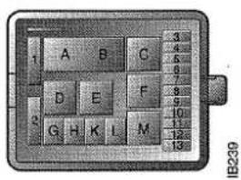
Arrangement of fuses on panel at back of glove compartment
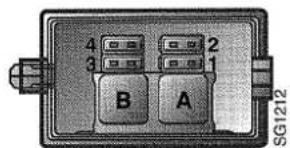
ABS fuse and relay panel
Fuses Function (A)
| Distribution box in glove compartment | ||
| 1 | ACC | 5 |
| 2 | Cruise control system; electric door mirrors | 10 |
| 3 | Belt warning; reading lights | 10 |
| 4 | Airbag | 5 |
| 5 | APC system | 10 |
| 6 | Ventilation fan | 30 |
| 7 | Headlamp wipers, el. adjustable seat | 10 |
| 8 | Windscreen wipers, rear windscreen wipers | 20 |
| 9 | Reversing lights; rear electric windows; sunroof | 30 |
| 10 | Heated seats | 20 |
| 11 | Front electric windows; relay reduced low beam (driving lights) | 30 |
| 12 | Indicators, beam length control | 15 |
| 13 | Instrument; EDU; injection system | 10 |
| 14 | Fuel pump | 20 |
| 15 | --- | |
| 16 | Central lock; interior lighting; courtesy lights; boot lighting; relay reversing light | 15 |
| 17 | ACC, EDU, luggage compartment light | 10 |
| 18 | Heated rear windscreen | 30 |
| 19 | Radio; electric aerial; clock; SCC | 15 |
| 20 | Option | max |
| 20 | ||
| 21 | Horn | 25 |
| 22 | Hazard warning lights | 15 |
| 23 | Engine electronics, test outlet | 5 |
| 24 | Brake lights | 15 |
| 25 | Electrically adjustable seat, driver | 30 |
| 26 | Electrically adjustable seat, passenger | 30 |
| 27 | Radio | 10 |
28 Pre-heated Lambda probe 25
29 Parking light R; rheostat; instrument lighting 15
30 Parking ligit L, glove compartment lighting 10
31 Driving lights 20
32 Rear fog light 15
Distribution box in engine compartment
1 Air pump (max) 30
1 Heat plates (Trionic) (max) 60
2 Radiator fan, 2 step (max) 30
3 Radiator fan, relay 5
4 Radiator fan (standard) 40
5 Dipped beam L 15
6 Dipped beam R 15
7 High beam L 15
8 High beam R 15
9 Relay, horn 5
10 Horn 25
11 A/C radiator fan/compressor 30
12 Extra lamp 15
13 Valve, air pump/vacuum pump 10
A-B Light relay
C Lamp test (pictogram)
D Air pump/heat plates/vacuum pump
E Radiator fan, 2 step
F A/C relay
G Extra light-fog light
H Pressure monitor A/C
K Reduced low beam (driving light)
L Horn
M Radiator fan
ABS fuse and relay panel
1 ABS pump 30
2 ABS 30
3 Pump and control unit, ABS 10
A Pump relay
B System relay
9000 Audio System
Tone controls
Bass ±10 dB at 100Hz
Treble ±10 dB at 10 000 Hz
Power output ____ 4 x 32 W (1 % THD 1 kHz)
Radio unit
Radiosystem ____ PLL synthesized
Frequency range
FM 87.5 MHz - 108 MHz
MW 531 kHz - 1602 kHz
LW 153 kHz - 279 kHz
Scanning steps
Automatic scanning ____ FM 100 kHz
MW 9 kHz
LW 3 kHz
Manual scanning ____ FM 50 kHz
MW 9 kHz
LW 1 kHz
Cassette player
Fast forward/rewind <130 sec (C-60)
Frequency response 50 Hz - 12500 Hz
Wow and flutter 0.1% WRMS
Stereo separation ____ >30 dB
Signal-to-noise ratio >45 dB
Dolby NR >53 dB
CD changer
1 bit "Bit Stream" 8 times oversampling ____
Number of discs 6 pcs
Frequency range ____ 5 - 20000 Hz
Dynamics 95 dB (1 kHz)
• Specifications comply with EIA Interim.
- For reasons of improvement we reserve the right to change specifications and appearance without prior notice.
- Dolby noise reduction is manufactured under license from Dolby Laboratories Licensing Corporation.
- "DOLBY" and the double D symbol are trade marks of the Dolby Laboratories Licensing Corporation.
| Manual gearbox | Automatic transmisson | ||
| Type ____ | 5-speed all-synchromesh with integralfinal drive and differential | Type ____ | 4-speed gearbox with torque converter, final drive and differential |
| Gearbox oil (for topping up) ____ | SYNTOMATIC | Selector lever positions ____ | PRND321 |
| Oil capacity ____ | 1.8 litres | Fluid capacity (incl. torque converter and oil cooler) ____ | 8.4 litres |
| Hydraulic clutch type ____ | Single dry-plate clutch of diaphragmspring type | When changing the oil, about 3.3 litres can be drained via the oil filter cover and oil filter (3 bolts) and drain plug on the final drive housing | |
| Speed in 5th gear (km/h) at 1000 rpm | Type ____ | ATF Dexron II | |
| 2.0i ____ | 37 | Middle East-market only: ATF Dexron IIE | |
| 2.0 t (150 hp) ____ | 41 | Hydraulically-operated plate clutches, brake bands and one-way | |
| 2.3 t (170 hp), 2.3 Turbo ____ | 45-46 | Hydraulic clutch type ____ | |
| Speed in 4th gear (km/h) at 1000 rpm | |||
| 2.0 t (150 hp), 2.3 t (170 hp), 2.3 Turbo ____ | 40-41 | ||
Wheel suspension
Spring type, front and rear ____ Coil springs
Maximum deflection of springs:
Front 185 mm
Rear 210 mm
Dampers, front and rear ____ Gas-filled telescopic
Brakes
Footbrake (ABS) ____ Hydraulic disc brakes with vacuum servo, 2 circuit diagonal system, (3 circuit system on 9000 Aero with TCS), ventilated discs on front wheels
Handbrake ____ Acts on rear-wheel
Brake fluid To DOT 4
Outher working diameters of discs:
Front 280 mm
Rear 258 mm
Total friction area of brake pads:
Front 192 cm²
Rear 72 cm ^4
Steering
| Steering mechanism ____ | Power-assisted steering of rack-and-pinion type with telescopic, jointed steering column shaft |
| Number of turns lock-to-lock ____ | 3,2 |
| Power steering fluid ____ | "Saab Power Steering Fluid 4634" |
Wheels and tyres
| Wheel sizes ____ | 6 J X 15" H2 or 6 1/2 J X 16" H2 |
| Compact spare wheel ____ | 3.5 B x 16 H2 |
| Spare wheel 175/70 (option) ____ | 5 1/2 J x 15" H2 |
| Tyre sizes | 195/65 R15 V205/55 R16 V or205/55 R16 W |
Compact spare wheel
Size T115/70
Tyre pressure 4.2 bar
Maximum mileage 3500 km
Maximum speed 80 km/h
Spare wheel (option)
Size 175/70 R15 T
Tyre pressure ____ 2.5 bar (36 psi)
Maximum speed 80 km/h
Winter tyre size
(with 6 Jx 15" H2 wheel) ____ 195/65 R15 MS
Winter tyre size
(with 6 Jx 15" H2 wheel) ____ 205/60 R15 MS
Winter tyre size
(with 6 1/2 J X 16 H2 wheel) ____ 205/55 R 16H MS
Front wheel alignment:
Front wheel alignment: Toe-in measured between rims 1.5 ± 0.5 m
Car identification
To identify the precise model of your car, it will help the Saab dealer if you quote the chassis number, engine number or gearbox number (see next page).
Australia only: The chassis number plate in the engine compartment also includes building year and month (above chassis No.)
Recommended pressures, cold tyres
| Tyre sizes | Load/speed (km/h) | Front and Rear bar/psi |
| 195/65 R15V | 1-3 pers/0-160 | 2.2/32 |
| Max. load/0-160 | 2.2/32 | |
| Max. load/160- | 2.6/38 | |
| 205/55 R16 V | 1-3 pers/0-190 | 2.2/32 |
| Max. load/0-190 | 2.2/32 | |
| Max. load/190- | 2.6/38 | |
| 205/55 R16 W | 1-3 pers/0-190 | 2.4/35 |
| Max. load/0-190 | 2.4/35 | |
| Max. load/190- | 2.5/36 | |
| 185/65 R15T M+S winter tyres | 1-3 pers/0-160 | 2.3/33 |
| Max. load/0-160 | 2.5/36 | |
| Max. load/160-190 | 2.7/39 | |
| 195/65 R15T M+S and 205/60 R15T M+S winter tyres | 1-3 pers/0-160 | 2.3/33 |
| Max. load/0-160 | 2.5/36 | |
| Max. load/160-190 | 2.7/39 | |
| 205/50 R16H M+S winter tyres | 1-3 pers/0-160 | 2.3/33 |
| Max. load/0-160 | 2.5/36 | |
| Max. load/160-210 | 2.9/42 | |
| T115/70 R16 spare wheel | Max. 80 | 4.2/60 |
| 175/70 R15 86T spare wheel | Max. 80 | 2.5/36 |
For each occupant less, the inflation pressure can be reduced by 0.1 bar. Max. load = 5 persons and luggage
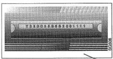
Chassis number
Body and trim colour plate
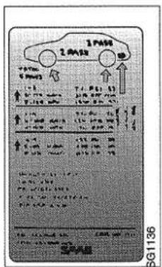
Chassis number


Marking plate for modification work

natural_image
Top-down line drawing of a car with visible structural lines and no text or symbolsChassis number plate


Gearbox number (manual gearbox)
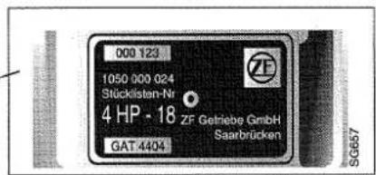
Transmission number (automatic transmission)
Engine number stamped on the engine block

natural_image
Technical line drawing of an internal combustion engine (no text or symbols present)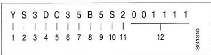
1 Geographical area Y = Northern Europe
2 Country S = Sweden
3 Motor manufacturer 3 = Saab Automobile AB
4 Product line C = 9000
5 Model series C = CS with driver airbag
D = CS with driver and passenger airbags
E = CSE with driver airbag
F = CSE with driver and passenger airbags
6 Body style 6 = 5-door
7 Gearbox 5 = Man. 5-speed gearbox
8 = 4-speed autom. transm.
8 Engine type J = 2.0 i
M = 2.3 turbo (200 hp)
T = 2.0 t (150 hp), low boost pressure
U = 2.3 t (170 hp), low boost pressure
R = 2.3 Turbo, (225 hp)
9 Check digit 0-9 or X
10 Model year W = 1998
11 Production locality 1 = Trollhättan
12 Serial number 000001-999999
Child restraint anchorages five-door models (Australia only)
To attach the restraints:
1 Remove the three covering plugs from the rectangular holes in the luggage compartment sill.
2 Fasten the anchor bolts with their shackles in the holes. Spacers are not required.
Bolt dimension: UNC 5/16, length 30 mm. Spacer dimension: 20 mm ø (hole 12 mm ø), thickness 10 mm.
Child restraint anchorages five-door models (Australia only)
1 Disengage the head restraint by pulling the catch upwards. Remove the head restraints by pulling upwards (outboard seating positions only).
2 Remove the covering plug(s) from the hole(s) in the parcel shelf.
3 Fasten the anchor bolt in the hole using the specially designed spacer.
Bolt dimension: UNC 5/16, length 30 mm.
Spacer dimension: 20 mm ø
(hole 12 mm ø), thickness 10 mm.
WARNING
Child restraint anchorages are designed to withstand only those loads imposed by correctly fitted child restraint. Under no circumstances are they to be used for adult seat belts, harnesses or for attaching other items or equipment to the vehicle.
Attachment hook
The attachment hook must be equipped with a plastic retaining clip (see figure) to prevent deformation of the securing tounge of the hook, which could cause disengagement of the hook.
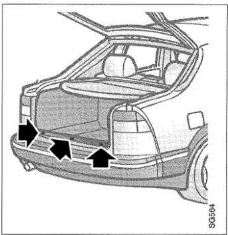
natural_image
Interior view of a car showing the rear window, side seats, and dashboard (no text or symbols visible)
natural_image
Top-down diagram of a car showing three black arrows pointing inward on the side panel (no text or symbols)
natural_image
Technical illustration of a mechanical clamp or bracket with no visible text or symbolsIndex
A
A/C, fault tracing ____ 110
A/C, maintenance 109
ABS brakes 78
ACC, programming 26
Aerial, mobile telephone 56
Air conditioning, fault tracing ____ 110
Air conditioning, maintenance ____ 109
Air distribution 19
Airbag 46
Alarm indication 65
Alarm, functions 68
Anti-theft alarm 65
Ashtrays 55
Audio system, data 123
Automatic 21
Automatic climate control (ACC) ____ 21
B
Ball pressure 83
Battery 96
Battery, jump starting 97
Belt guides, belt 44
Bonnet 64
Brake fluid 95
Brake system, technical data ____ 125
Bulbs, changing 100
C
Calibration, ACC 26
Can holder 57
Car care 89
Car condition 81
Catalytic converter, information ____ 72
Central locking 60
Changing bulbs 100
Changing the wheels 107
Changing, bulbs 100
Chassis number 126
Child safety lock, rear door 60
Child safety seats 51
Clock 9,12
Colant, changing 93
Colour code, paint 126
Colour code, upholstery 126
Compact spare wheel 109
Coolant 93
Corrosion protection 113
Cruise Control 77
Cruise control 77
Cup holder 57
D
Dampers 125
Daylight driving lights 15
Defroster 25
Deprogramming the ACC ____ 26
Detachable towing hitch 84
Direction indicators 16
Drive belt 120
Drive belt, generator 98
Driving in a hot climate 82
Driving in winter weather 81
Driving technique 80
E
ECON 23
Economical 79
EDU 10
EDU, changing units 11
EDU, resetting 11
Electrical system, technical data ____ 120
Electrically adjustable front seats ____ 43
Electrically heated door mirrors 20
Electrically heated rear window 20
Electrically heated seat 44
Engine bay, washing 111
Engine serial number 126
Engine speed limitation 9
Engine, description 90
Engine, technical data 118
Extra fog lights 18
F
Fan belt 120
Fault diagnosis, A/C 109
Flat patch, tyre 109
Fluid level, automatic transmission ____ 92
Foreign journeys 114
Fuel 73
Fuel consumption 10
Fuel filler flap 64
Fuel gauge 7
Fuses 105
Headlamps 15
Headlights 15
1
Indicator and warning lamps 6
Indicator lamps 6
Instrument 9
Instrument lighting 17
Interior lighting 18
Interior temperature, ACC 23
Luggage compartment 61
Luggage compartment lighting ____ 18
M
Main beam flasher 15
Main fuse box 105
Main instrument display panel 6
Manual heating and ventilation system 19
G
Gearbox number 126
Gearbox, technical data 124
Generator 98
Generator belt 120
Generator, charging 120
Glass breakage sensor 65
Glove box 56
Grade of oil 118
J
Jump starting with extra battery 97
K
Kickdown 76
H
Hazard flashers 17
Head restraint 42
Headlamp alignment 100
Headlamp beam adjustment 15
L
Labels 2
Leather upholstery, care and
maintenance 111
Load securing lugs 61
Lock 60
0
Odometer 9
Oil capacity, engine 118
Oil change, engine 91
Outside temperature 10
P
Paintwork, touching-up 112
Parking lights 15
Periodic service 113
Pictogram 8
Power steering fluid 96
Pressure gauge 9
Programming the ACC system ____ 26
Q
Questions about airbag 49
R
Radio 27
Rear fog light 16
Rear window wiper 18
Refuelling 73
Reversing lights 17
Rheostat 17
Roof load 85
Running-in 79
S
Saab European Service Guide 114
SCC trip computer 11
Seat belts 44,110
Service programme 113
Shifting the wheels round 107
Snow chains 81
Spare wheel 109
Spark plugs 120
Speed rating code ____ 106
Speedometer 9
Spolare 98
SRS, supplementary restraint system ____ 46
Starting the engine 70
Steering wheel adjustment 44
Steering, technical data 125
Stone damage, repairs 112
Sunroof 54
Switches 15
T
Table of fuses 121
Tachometer 9
Temperature control 19
Temperature gauge 9
Textile carpets 111
Tightening torque, wheel bolts ____ 107
Tips on the ACC 26
Tools 63
Torkarblad, byte 98
Torkarblad, strålkastare 98
Torkare och spolare 98
Touching-up the paintwork 112
Towing 86
Towing attachment 82
Trailer weight 83
Travelling in another country 114
Tripcomputer 10
Tripmeter 9
Turbo gauge 9
Turbo, driving information 71
Tyre designations 106
Tyres 106,125
U
Upholstery 111
V
Vanity mirror 54
Ventilation fan 19
Viscosity, motor oil 118
W
Warning labels 2
Warning triangle 17
Washing 112
Washing, engine bay 111
Waxing and polishing 112
Wear indicators 107
Wheel suspension 125
Wheels and tyres 106, 125
When travelling abroad 114
Window lifts 53
Wiper/washer 17
Fuel
Unleaded petrol
Recommended 95 RON, min. 91 RON
Turbo engine 2.3 litre (225 hp): recommended 98 RON, min. 91 RON
Insert the fuel pump nozzle past the flange in the filler pipe and rest its first position marking (ring, "pimples" or the first turn of the spring) against the flange. Do not lift the nozzle while filling up is in progress.
Note: Do not fill fuel all the way up in the filler pipe. The petrol must be allowed room for expansion.
Fual tank capacity: 66' litres

SG1342
7 Coolant
The level should not be allowed to fall below the MIN mark on the expansion tank.
Top up as necessary with equal parts of Saab coolant and water. Take care when opening the bonnet if the engine is boiling. Never open the filler cap on the expansion tank while the engine is hot.
The cooling system is pressurized. Always open the filler cap on the expansion tank carefully to release the pressure before removing the cap completely.
1 Engine oil
Saab Turbo Engine Oil or an oil which meets the requirements of API Service SG or CCMC G4 or G5 having a viscosity of 10W/30, 10W/40, 5W/30 or 5W/40.
2 Brake/Clutch fluid
Brake fluid to DOT 4.
3 Battery
4 Washer fluid
5 Automatic transmission fluid
Grade of fluid: ATF Dexron II
6 Power steering
Power steering fluid: "Saab Power Steering Fluid 4634"

SAAB
Saab Automobile AB, Trollhättan, Sweden
ENG Part No. 41 26 68 Printed in Sweden on chlorine-free paper © Copyright Saad Automobile AB, 1997
- Saab 9000
- Owner's Manual
- Saab 9000 M 1998
- Battery:
- A/C system:
- Introduction
- WARNING
- IMPORTANT
- Instruments and controls
- Main instrument display panel
- Indicator and warning lamps
- Main beam indicator light
- Washer fluid indicator light
- ABS warning light
- Charging warning light
- Indicator lamps, fuel gauge
- Rear fog lamp indicator light
- Warning lamp, handbrake
- Indicator for headlights and parking lights
- Indicator lamp, Cruise Control System
- Brake warning light
- Indicator light for rear-window heating
- Oil pressure warning light
- Pictogram
- Warning light for airbag - Supplementary Restraint System (SRS) (option)
- Instruments
- Tachometer
- Speedometer, odometer and trip meter
- Pressure gauge (2.3 Turbo only)
- Temperature gauge
- Clock
- Trip computer
- Changing units
- Resetting
- Switching the display on/off
- Error codes
- ARRIVAL
- ALARM
- DISTANCE TO DESTINATION
- AVERAGE SPEED
- SPEEDING ALARM
- SELECTING THE UNITS
- Switches
- The lighting is off
- Parking lights
- Headlights
- Main/dipped beam
- Headlight flashing
- Headlight beam-length adjustment
- Rear fog light
- Direction indicators
- Reversing lights
- Instrument lighting
- Hazard flashers
- Stalk switch for wipers and washers
- Rear window wiper/washer
- Interior lightning
- Switch for interior lighting
- Luggage compartment lighting
- Fog lights
- Handbrake
- Manual heating and ventilation system
- Fan
- TEMP
- Temperature control
- DISTR
- Air distribution
- Heated rear window and door mirrors
- To obtain maximum heating in very cold weather
- Automatic climate control (ACC)
- Setting the required temperature
- Functions
- AUTO
- ECON
- OFF
- Defroster
- Defroster/Floor
- Floor
- Floor/panel
- Panel
- Programming the ACC system
- Cancelling ACC programming
- Hints and tips:
- Calibration
- Special climatic conditions
- Audio System (option)
- ON/VOL - on/off, volume
- EQ/BAL Bass, treble, balance, fader
- EQ/BAL - Loudness
- BAND - Waveband selector
- Tuning and seek-tuning
- Quick selection buttons 1-6
- PS/AS- Automatic station memory
- SOURCE - source selector
- RDS - Radio Data System
- RDS - PTY function (Programme TYpe)
- TA - Traffic Announcement (traffic reports)
- TP - Traffic Programme
- EON - Enhanced Other Network
- Alarm interruption
- TA - REG (REGional)
- Cassette player
- Cassette changeover
- Fast Forward, Rewind and Music Search
- Cassette Eject button
- SCN - 10 second playback of every track
- BLS - (BLank Skip)
- Dolby ® , noise reduction
- RPT - (RePeaT) - Track repeat
- Metal tapes
- Cassette care
- CD player (option)
- Using the CD player
- Normal playing
- Display
- Moving forward on the CD
- Moving back on the CD
- CD Changer
- Playing CD's
- DISC
- FWD/REW
- RDM - (RanDoM) - Random playback
- SCN - 10 second playback of every track.
- RPT - (RePeaT) - To repeat a track or a whole disc
- Anti-theft lock
- Telephone controlled lowering of volume
- Adjusting the preset volume of traffic messages
- Mobile telephone and communications radio
- Interior equipment
- Seats
- Head restraint
- Electrically adjustable front seats
- Electrically heated driver's and co-driver's seats
- Steering wheel adjustment
- Seat belts
- Pregnant women
- Airbag (SRS)
- Driver's seat
- Front passenger airbag
- Disconnection of the airbag on the passenger's side.
- Common questions about airbag
- Child safety
- Saab child safety seats
- Rear-view mirrors
- Electric windows
- Opening:
- Closing:
- Child-proofing, rear electric windows (ON/OFF)
- Sunroof
- Illuminated make-up mirrors
- Ashtrays
- Audio equipment
- Glove compartment
- Can holder
- Doors, locks and luggage compartment
- Doors and locks
- Luggage compartment
- Tools
- Bonnet
- Emergency opening of the fuel filler flap
- Anti-theft alarm
- Glass break sensor
- Doors
- Hood
- Tailgate
- Signals when the alarm is tripped
- Starting and driving
- Ignition switch and steering lock
- LOCK - Locking position
- OFF-position
- ON-position
- Check-mode position
- ST - Starting position
- Starting the engine
- Important points to note when driving the Saab 9000 Turbo
- Important considerations for cars with catalytic converter
- Running in
- Running-in of new brake pads
- Refuelling
- Gear changing
- Manual transmission
- Automatic transmission
- Positions of selector lever
- P
- R
- N
- D
- 3
- 2
- 1
- Kick-down
- Cruise control
- To select the required speed
- To increase the selected speed
- Temporary increase in speed
- Reduction in speed
- Resume
- Disengaging the system
- Braking
- Anti-lock brakes (ABS)
- Economical motoring
- Conditions affecting fuel consumption
- Running-in
- Weather conditions
- Driving technique
- Road conditions
- Car condition
- Driving in winter weather
- Driving in hot weather
- Towing a trailer or caravan
- Towing attachment
- Trailer (or caravan) weight
- Towing attachment load
- Driving
- Instructions for detachable towing attachment
- To fit
- To remove
- Driving with the compact spare wheel fitted
- Spare tyre 175/70 R15 T
- Driving with a roof-rack road
- Driving with the luggage compartment door open
- Towing
- Car care and maintenance
- Engine compartment, Turbo models
- Engine
- Engine oil
- Gearbox oil
- Manual gearbox
- Gear changing - automatic transmission
- Coolant
- Changing the coolant
- Radiator assembly
- Brake fluid and brake pads
- Checking
- Steering system
- Battery
- Boost starting using jump leads
- Alternator
- Wipers and washers
- Changing the windscreen and rear window wiper blades
- Changing the headlight wiper head
- Washers
- Headlamp alignment
- Headlight alignment
- Changing bulbs
- Changing the headlight bulb
- Headlights, dipped beam and parking lights
- Headlight, full beam
- Front light clusters
- Front light cluster
- Rear light clusters
- Rear lights
- High-level brake light
- Side direction indicators
- Door lights, number plate light and luggage compartment light
- Dome light
- Rear-view mirror light
- Rear reading lights
- Seat belt warning light
- Other lights
- Fuses
- Wheels and tyres
- Tyres
- Tyre designations
- Other speed rating codes
- Tyre pressures
- Wear indicators
- Switching wheels
- Changing the wheels
- Compact spare wheel
- Flat spots
- Air conditioning (A/C)
- Fault diagnosis
- Maintenance and servicing
- Upholstery and trim
- Cleaning and caring for leather upholstery
- Textile carpeting
- Engine compartment
- Washing the car
- Washing and polishing
- Touching-up the paintwork
- Two-coat paint
- Anti-corrosion treatment
- Service programme
- Periodic service
- Motoring abroad
- Technical data
- Chassis number plate in engine compartment
- Fuses and relays
- Distribution box in engine compartment
- ABS fuse and relay panel
- Audio System
- Tone controls
- Radio unit
- Car identification
- Child restraint anchorages five-door models (Australia only)
- Attachment hook
- Index
- A
- B
- C
- E
- F
- M
- G
- J
- K
- H
- L
- 0
- Q
- S
- T
- U
- V
- W
- Fuel
- Unleaded petrol
- Coolant
- Engine oil
- Brake/Clutch fluid
- Battery
- Washer fluid
- Automatic transmission fluid
- Power steering
- SAAB
Marque : SAAB
Modèle : 9000 (1998)
Catégorie : Voiture