
GP-360ML - Radio communication ICOM - Notice d'utilisation et mode d'emploi gratuit
Retrouvez gratuitement la notice de l'appareil GP-360ML ICOM au format PDF.


| Type de produit | Récepteur GPS maritime haute résolution |
| Marque | ICOM |
| Modèle | GP-360ML |
| Dimensions (L x H x P) | 249 × 150 × 78,7 mm |
| Poids | 1,86 kg (4,10 lb) |
| Alimentation | 10 - 32 VCC, 0,9 A |
| Écran | LCD haute résolution, rétroéclairage réglable |
| Récepteur GPS | 12 canaux parallèles (poursuite jusqu'à 12 satellites) |
| Précision de position (typique) | 50 m (SA ON), 10 m (SA OFF) |
| Précision de vitesse (typique) | 0,80 nœud (SA ON), 0,10 nœud (SA OFF) |
| Temps de premier fix (typique) | Démarrage à chaud : 20 s ; à froid : 60 s ; première recherche : 2,5 min |
| Vitesse maximale | 5000 nœuds |
| Fréquence de mise à jour | Environ 1 fois par seconde |
| Capacité des waypoints | 500 waypoints (nom, icône, date/heure, méthode de création) |
| Routes | 50 routes, jusqu'à 50 waypoints par route |
| Chemins (tracés) | 10 chemins, jusqu'à 500 points au total |
| Cartes électroniques | Carte mondiale intégrée + cartouches Navionics (optionnelles) |
| Fonctions de navigation | Guidage vers waypoint, route, chemin ; affichage cap, distance, écart de route ; alarmes (arrivée, ancre, écart, frontière, etc.) |
| Autres fonctions | Prédiction des marées, lever/coucher du soleil/lune, calcul distance/relèvement entre waypoints, simulateur de navigation |
| Connectivité | 3 ports série (NMEA 0180/0183, entrée/sortie), interface pilote automatique |
| Résistance à l'eau | JIS-4 (résistant aux éclaboussures) |
| Température de fonctionnement | -10°C à +65°C (14°F à 149°F) |
| Entretien | Nettoyer avec un chiffon doux imbibé d'eau savonneuse ; ne pas utiliser de solvants organiques ; remplacer la batterie interne tous les 5 ans |
| Sécurité | Mise à la terre obligatoire ; ne pas exposer à des gaz inflammables ; couper l'alimentation en cas de fumée ou odeur ; ne pas ouvrir le boîtier |
| Contenu de la boîte | Navigateur GP-360ML, antenne GPS avec câble 7,6 m (25 pi), câble d'alimentation/données, support de montage, manuel d'utilisation, carte de garantie |
FOIRE AUX QUESTIONS - GP-360ML ICOM
Questions des utilisateurs sur GP-360ML ICOM
0 question sur cet appareil. Repondez a celles que vous connaissez ou posez la votre.
Poser une nouvelle question sur cet appareil
Téléchargez la notice de votre Radio communication au format PDF gratuitement ! Retrouvez votre notice GP-360ML - ICOM et reprennez votre appareil électronique en main. Sur cette page sont publiés tous les documents nécessaires à l'utilisation de votre appareil GP-360ML de la marque ICOM.
MODE D'EMPLOI GP-360ML ICOM
GP-360ML
HIGH RESOLUTION GRAPHIC RECEIVER
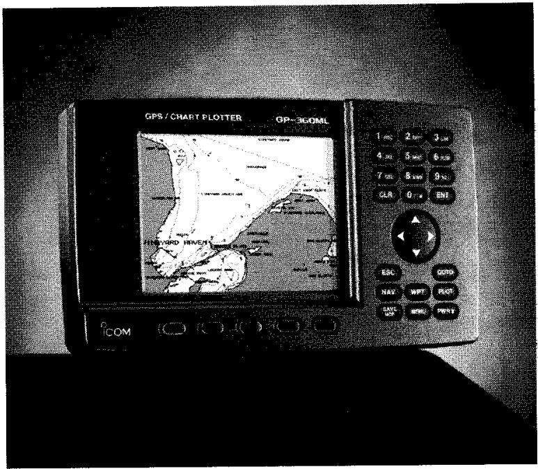
OPERATORS MANUAL
MASTER
Do Not Remove
From Tech Support Area
OICOM
WELCOME TO ICOM AMERICA'S FAMILY OF PRODUCTS
Thank you for purchasing your new ICOM GP-360ML GPS receiver. ICOM products are known around the world as the best in marine communications and navigation. If you have questions concerning other ICOM products, or if you still have unanswered questions about your new GP-360ML after reading this operator manual, please contact us or visit our Web site.
ICOM America, Inc. 2380-116th Ave. NE Bellevue, WA 98004
Customer Service: (425) 454-8155
Tech Support:
Phone: (425) 454-7619
Fax: (425) 454-1509
E-mail: marine@icomamerica.com
Web: www.icomamerica.com
GPS signals most frequently receive close to 1000 msclosures under 35 and inside buildings . When the view of the sky is obscured ,
- Position and speed change when time as the satellites change their positions in the sky. Errors will occasionally be much larger than normal when the satellite geometry is unfavorable.
GPS signals most frequently receive close to 1000 msclosures under 35 and inside buildings . When the view of the sky is obscured ,
- Position and speed change when time as the satellites change their positions in the sky. Errors will occasionally be much larger than normal when the satellite geometry is unfavorable.
$$ \begin{array}{r} {{\mathbf {j} _ {\mathrm {金 融}} \cdot \hat {\mathbf {\mathrm {音}}} _ {1} \cdot \hat {\mathbf {\mathrm {的}}} _ {2} = \mathrm {一 个 确 保} _ {m n} ^ {2} + \frac {1}{2} \delta_ {m n} \cdot \hat {\mathbf {j}} _ {1} \cdot \hat {\mathbf {j}} _ {2},}} \end{array} $$
1
( a^n + b^n) ( a^n - b^n) = a^n - b^n
Each of the following warning notices indicates that neglecting the suggested procedure or practices may result in death or serious personal injury.
- Be sure to turn off the power by pressing and holding the power key or disconnect the power cable from the battery immediately if the product ever produces smoke or smells of something burning.
Failure to do so may cause a fire or electric shock. Contact your dealer or our service personnel for inspection.
- Do not install the product in areas where it is exposed to flammable gases.
Doing so may cause a fire or an explosion.
- Supply the product with the specified voltage or use the specified power supply. See Appendix G SPECIFICATIONS.
Otherwise, a malfunction or fire may result.
- Use the specified fuse.
See Appendix G SPECIFICATIONS.
Otherwise, a malfunction or fire may result.
- Do not remove the cover and touch internal parts of the product.
Doing so may case death due to a high voltage inside the product.
Servicing and adjustment of the product must be performed by an authorized dealer or service center.
- Be sure to electrically ground the product to the hull.
Failure to do may cause electric shock.
- Be careful to prevent foreign objects from entering the product.
Foreign objects including metal chips, wire scraps and liquids inside the product may cause a short circuit, fire or malfunction.

CAUTION
Each of the following caution notices indicates that neglecting the suggested procedure or practices may result in personal injury or property damage.
- This product is not intended for use as the sole marine navigation tool.
For detailed and latest information for navigation, consult nautical charts and Notices to Marines.
- Always hold the plug when removing the power cables from the power supply.
Pulling the power cable may cause damage to the power cable and a fire or electric shock.
- Do not install the product and antenna in areas other than specified.
Doing so may cause an accident or a malfunction
- Do not expose the product directly to water.
- Never modify or attempt to repair the product by yourself.
Doing so could cause a malfunction or fire
Only authorized dealers and service centers are allowed to modify or repair the product.
OTHER PRECAUTIONS
- Do not install the product close to speakers, power transformers or other equipment that produce a magnetic field.
- When starting the engine of the ship involves a rapid fall in supply of voltage to the product be sure to start the engine before powering on the product.
- Avoid using organic solvents such as thinner or benzene to clean the product. These solvents will cause damage to the product surface. To clean the product or antenna, wipe it using a soft cloth damped with a water-diluted detergent.
- The product contains a lithium battery (having a life of approx. 4 years) which retains GPS positioning data. If this backup battery is completely dead, the GPS almanac data is lost and it will take a long time to acquire navigational satellites. Registered navigational marks and routes are also lost.
NOTE:
- The LCD is a high-density type having an affective pixel percentage of at least 99.99% . It may have an ineffective pixel or "always active" pixel percentage of max. 0.01% under normal conditions. If there are clarity problems, please contact your nearest service center.
- The LCD is a consumable component. When the service life expires the LCD screen will darken, flicker or provide no display. At the first sign of these symptoms, the LCD should be replaced. Consult your authorized dealer or our service personnel.
TABLE OF CONTENTS
GETTING STARTED
1.1 Navigation
1.2 GPS
1.3 Using the Keypad
1.4 Turning Power On and Off
1.5 Adjusting the Backlight
1.6 Displaying Position
1.7 The World Map
1.8 Displaying a Chart
1.9 Setting Time
1.10 Entering a Waypoint
1.11 Saving Your Starting Position
1.12 Steering to a Waypoint
1.13 Returning Home
2 BASIC OPERATION
2.1 Summary of Basic Operation
2.2 Customizing the GP-360ML
3 CHARTS
3.1 Electronic Chart Cartridges
3.2 Inserting and Removing Cartridges
3.3 Displaying your Position on a Chart
3.4 Zoom Levels
3.5 AUTOZM
3.6 Navigation Aids - Lights and Buoy
3.7 Chart Display Setups
4 WAYPOINTS
4.1 Waypoints
4.2 Creating a New Waypoint
4.3 Day and Time of Waypoint Creation
4.4 Finding a Waypoint
4.5 The List of Nearest Waypoints
4.6 Going to a Waypoint
4.7 The Save Key
4.8 Man Overboard
4.9 Deleting a Waypoint
4.10 Deleting All Waypoints
4.11 Range and Bearing from One Waypoint to Another
4.12 Other Methods of Creating Waypoints
5 TRACK PLOTTING
5.1 Automatic Position Recording
5.2 Plot of Previous Track
5.3 Using the Previous Track to Return Home
5.4 Storing and Displaying Paths
5.5 Following a Path
6 ROUTES
6.1 Courselines, Legs, and Routes
6.2 PresentCourseline
6.3 Route Navigation
6.4 Creating a Route
6.5 Following a Route
6.6 Editing and Deleting Routes
SUNRISE, SUNSET, AND TIDES
7.1 Sunrise and Sunset
7.2 24 Hour Tide Prediction
8 CUSTOMIZING SETUP CHOICES
8.1 Operation Setup
Display Contrast
Language
Beeper
GMT Offset
Single Fix Mode
Nav Simulator
Erase all Waypoints
8.2 Navigation Setup
Lat/Lon Format
MGRS/UTM/TD Coordinates
Units of Measurement
Altitude
Magnetic Variation
Map Datum
8.3 Alert Setup
Waypoint Arrival
Crosstrack Error
Border Crossing
Anchor Watch
Alarm Clock
Watch Timer
Down/Race Timer
Avoid Points
8.4 Track Log Setup
Recording to Limit Position Error
Recording at Equal Time Intervals
8.5 Serial I/O Setup
Input/Output Port 1
Output Port 2
View Serial Input Data
8.6 Steering Setup
Crosstrack Error Scale
Parallel Route Offset
Specified Track Angle
APPENDIX
A GLOSSARY
B MGRS AND UTM COORDINATES
C LORAN C COORDINATES
D MAP DATUMS
E USER DEFINED DATUM
SPECIFICATIONS
G INSTALLATION AND ELECTRICAL WIRING
H SERIAL DATA INPUT AND OUTPUT
INDEX
GETTING STARTED
1.1 NAVIGATION
The purpose of a GPS receiver is to help you with navigation, so we will start out by reviewing some of the terms used in this manual.
NAVIGATION is the process of determining your position, plotting a course over which you wish to travel, and steering your vessel over that course.
POSITION is your exact location on the Earth. For marine navigation, this is expressed as two coordinates, latitude and longitude.
LATITUDE is the number of degrees you are north or south of the Equator, and lines of latitude are sometimes called parallels.
LONGITUDE is the number of degrees you are east or west of the zero degrees longitude line, which passes through Greenwich, England. Lines of longitude are sometimes called meridians, and they all pass through both the North and South poles.
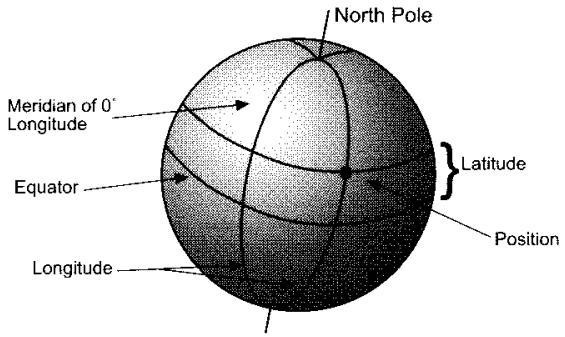
WAYPOINTS are precisely specified locations on the Earth. They can be used to mark your destination (where you want to go), or points along the route to your destination. Each waypoint can be specified by its latitude and longitude.
HEADING is the direction your boat is pointing.
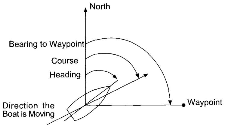
COURSE (sometimes called TRACK) is the direction your boat is moving over the surface of the Earth.
BEARING is the direction to a specific point, such as a waypoint or destination.
1.2 GPS
GPS is short for the Global Positioning System. It consists of 24 satellites, which transmit radio signals that can be used to compute position, course, and speed.
A GPS receiver receives the signals from the satellites, and computes position, course, and speed. After you turn power on, it takes anywhere from a few seconds to a few minutes to find the GPS signals, and compute the first position fix. The readings from a GPS receiver will have the following typical errors:
Position 50 meters (164 feet)
Speed 0.5 knots
Errors may sometimes be much larger, when the satellite positions in the sky are not favorable, or when the lines of sight from the satellites to the antenna are obstructed by masts, boat structure, trees, buildings, or bridges.
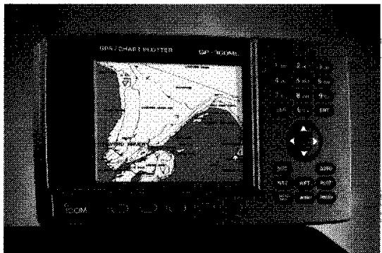
1.3 USING THE KEYPAD
PWR* The [POWER] key turns the GPS on, and controls the intensity of the keyboard/screen lighting. To turn the GPS off, hold the POWER key down for three seconds.
NAV Pressing the [NAV] key will step through the display screens showing position, course, speed, and steering information.
WPT Pressing the [WPT] key will bring up the Waypoint screen.
PLOT The [PLOT] key brings up the plot of present position and previous ground track, and an electronic chart. Pressing the PLOT key again will expand the plot area by deleting the numerical information.
MENU The [MENU] key brings up the main menu, from which submenus can be selected. The main menu and submenus allow for the selection of display screens that are not often used, as well as the control and setup of all of the choices and variables in the GPS.
SAVE The [SAVE] key is used to save present position in a new waypoint. Saved waypoints are automatically given the names S001, S002, S003, etc. Pressing the SAVE key twice executes the MAN OVERBOARD function, which saves present position and immediately provides a steering display back to the saved position.
GOTO The [GOTO] key is used to go to a waypoint, a route, or a path. Bring up the screen which shows the waypoint, route, or path, and press the GO TO key. The screen will then give you steering instructions to go to the waypoint, or to the closest point of the route or path. The GOTO can also create a Waypoint. By moving the cursor away from your present location and pressing the GOTO key, the unit will select the next Waypoint number available.
ESC The [ESC] key is used to go backward in the screen sequence; That is, to escape from the currently displayed screen to the previous screen.

The UP and DOWN keys are used to highlight a field. After [ENT] has been pressed to start data entry, the up and down arrow keys will step through numbers and letters to set up data input.

The LEFT and RIGHT keys are used to highlight a field. When the highlighted field is the name of a waypoint, route, or path, they can be used to scroll through all of the names in your library. After [ENT] has been pressed to start data entry, the left and right arrow keys will move the character highlight to the left or right, which selects the next character for input.
ENT The [ENT] key is used to start data entry, to finish data entry, and to select a highlighted item, and to enter a field.
CLR Once you have entered a field the [CLR] key can be used to start data entry by first clearing the field.
0-9 The 10 numbered keys are used to key in numbers, just like an electronic calculator. They can also be used to key in letters, by pressing the key several times to step through the three letters shown on the key.
The five keys under the screen, with no key legends, are called "soft" keys, because their functions are defined by software. Their function is shown on the screen, just above each key.
1.4 TURNING POWER ON AND OFF
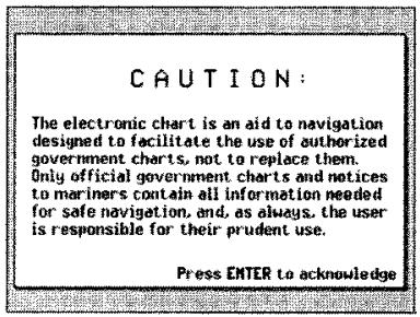
Power is turned on by briefly pressing the [PWR*] key. The "ICOM GP-360ML" screen will be displayed for a few seconds, followed by CAUTION screen. The CAUTION screen displays a warning that electronic charts are only aids to navigation, and do not replace paper charts, which contain the most complete information needed for safe navigation. After reading the warning, press [ENT] to continue.
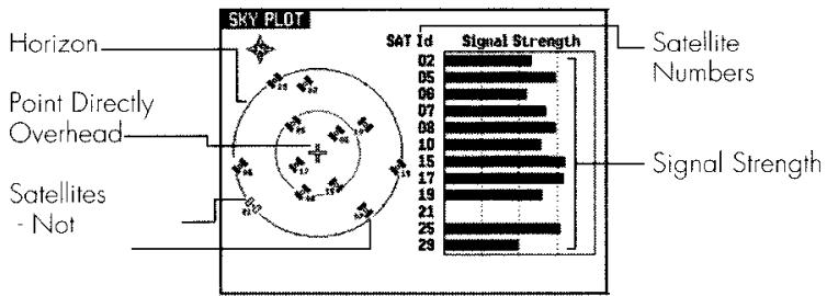
The satellite status screen will be shown next. The satellite status screen is shown until enough satellite signals are found to compute a position fix, then it will change to the PLOT screen.

NOTE: If any key is pressed prior to the GP-360 acquiring satellites, it will not automatically switch back to the PLOT screen, even if you go back to the SKY PLOT screen.
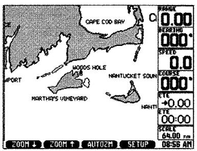
The GPS will start searching for the satellites immediately after it is turned on. The first time it is turned on, (or whenever it is moved more than 100 miles from where it was last operated) it will take two to five minutes to find the satellites and compute the first position fix. When it does, the screen will shift automatically to the PLOT screen. The GP-360ML is turned off by pressing the [PWR*] key, and holding it down for three seconds.
1.5 ADJUSTING THE BACKLIGHT
After power is turned on, the light intensity can be adjusted with the [PWR] key. Pressing this key a number of times will step the light intensity up to its maximum value, turn it off, and then increase it again.
1.6 DISPLAYING POSITION
The position screen can be brought up at any time by pressing the [NAV] key.
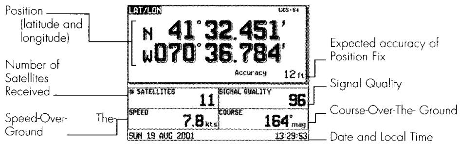
The number displayed after ACCURACY is the expected accuracy of the position fix. The actual position error will be less than the accuracy number about half of the time, and greater about half of the time.
The Quality number shown on the bottom right part of the screen tells you how reliable the position fix is likely to be.
QUALITY POSITION FIX RELIABILITY
40-99 Good position fix all the time
30-40 Occasional times of no position fix
20-30 Frequent times of no position fix
0-20 Usually no position fix
The displayed latitude and longitude can be shown on a marine chart by pressing the [PLOT] key.

NOTE: Before the GPS has had time to acquire enough satellites to compute an accurate position fix, a warning message "NAV DATA MAY BE INACCURATE" will be shown periodically. Whenever this message is shown, don't use the displayed information for navigation purposes.
1.7 THE WORLD MAP
The GP-360ML contains a world map, that shows the shorelines of most of the world. This can give you an idea of approximately where you are with respect to land.
For more accurate electronic charts, you will have to insert a NavChart cartridge in the GP-360ML. These chart cartridges are made by Navionics, cover most shorelines of the world, and are available at most large marine stores. Each cartridge includes several marine charts, and provides especially fine detail in harbors, ports, and marinas.
1.8 DISPLAYING A CHART
To display a chart, first insert the appropriate cartridge in the cartridge slot in the lower right hand corner of the case. Detailed instructions are given in Section 3.2. Then press the [PLOT] key to display the chart.
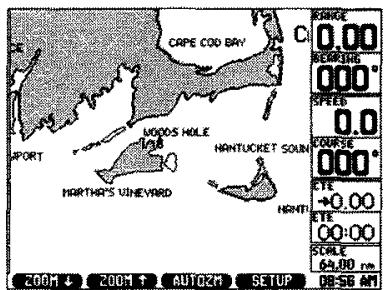
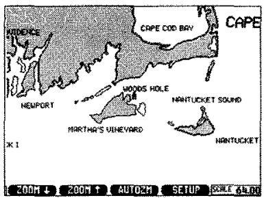
Water is white, land is gray. The chart scale, shown in the lower right hand corner, can be increased or decreased by pressing the [ZOOM IN] and [ZOOM OUT] soft keys. The position of your boat is shown by the boat symbol in the middle of the screen. The chart area can be made larger by pressing the [PLOT] key again, which will cause the numerical data to be dropped. It can be restored by pressing the [PLOT] key again.
1.9 SETTING TIME
To set the local time:
- Press the [NAV] key once, to bring up the first NAV screen.
- Press the [UP] or [DOWN] keys to highlight the time field, located in the lower right corner of the screen.
- Determine your local time accurate to within ten minutes. It must be in a 24 hour form. (IE, 2:00 pm is entered as 14:00.)
- Press [ENT] to begin the time entry.
- Key in the time using the numbered keys. For example, to key in 2:35 pm, press 1, 4, 3, 5.
- Press the [ENT] key to complete the time entry. A window will open and ask: Standard or Daylight Savings time. Make the appropriate selection. If the receiver is tracking any satellites, the approximate time you entered will change to the correct time, accurate to within one second, with hour and half hour time zones taken into account.
If you are in a time zone with 1.5 minute offsets from Greenwich time, read about GMT Offset in Section 8.1.

NOTE: When it is time to set clocks forward or back because of Daylight Saving Time, just enter the new time in the first NAV screen.
You are now ready to begin navigating.
As soon as you are more familiar with the GP-360ML, you can review all of the SETUP possibilities, and customize your GPS to give you the most useful screens. For now, we will go on and learn more about using the GPS for navigation.
1.10 ENTERING A WAYPOINT
Suppose that you're starting out from Falmouth, Massachusetts, and want to go to the harbor entrance at Edgartown, on Martha's Vineyard. You look up the latitude and longitude coordinates of the entrance on a chart, and find that they are:
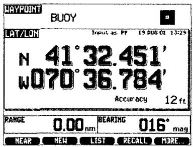
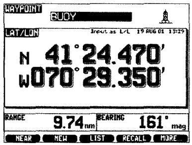
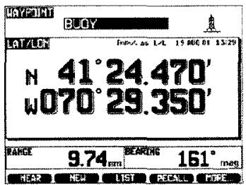
Harbor Entrance Latitude n 41^24.47' Longitude w 070^29.35'
To be able to navigate toward the buoy, you'll first have to enter the buoy coordinates into a waypoint.
- Press the [WPT] key to bring up the first waypoint screen.
- Press the NEW soft key, under the screen.
- A new waypoint will now be created. The highlight will be in the name field, which has been set to a default value of WPO01, WPO02, or a similar name. We want the new waypoint to be named BUOY. Press [ENT] to begin entry of the waypoint name. A blinking cursor will appear in the first (leftmost) character of the name.

- To set B into the first character of the name, press the key with the desired letter on it ([1ABC], in this case) a number of times until the desired letter appears on the screen.
[A] Press once
[B] Press twice
[C] Press three times
[1] Press four times
- Press the right arrow key once to move the highlight one space to the right.
- To set up the letter U, press the [7STU] key a number of times until U appears on the screen (three times, in this case).
- Press the right arrow key once to move the highlight one space to the right.
- Continue until the desired name is on the screen. If you make a mistake, you can press the left arrow key to move the cursor to the left.
- Press [ENT] to complete entry of the waypoint name.
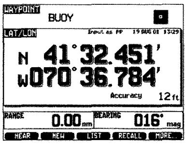
The highlight will move to the waypoint icon field. To enter an icon:
- Press [ENT] to begin entry of an icon.
- Press the four arrow keys to highlight the icon you want. Then press [ENT].
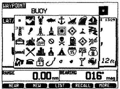
After the Icon entry, the highlight will move to the latitude field. To enter the latitude:
- Press [ENT] to start the entry process. The cursor will be on the first digit.
- The default choice is north latitude. If you want to change this to south, press the left arrow key to move the cursor to the N/S field, and then press the and keys. An S will be put in, press the key, the cursor will move to the first number to be entered.
- Key in the desired latitude, using only as many digits as you need. For example, to put in a latitude of n 41^ 24.47' , press 4, 1, 2, 4, 4, 7.
- Press [ENT] to complete the latitude entry.
The highlight will now be in the longitude field. Repeat steps 1-4 to enter the longitude.
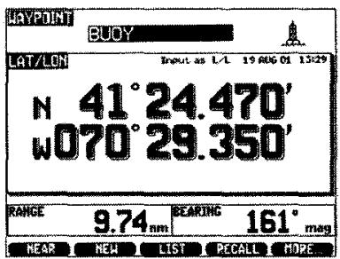
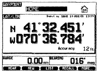
You have now entered a waypoint, and are being shown the distance and magnetic bearing angle from your present position to the waypoint! This corresponds to the following screen.
ENTERING A WAYPOINT GRAPHICALLY
You have just entered a waypoint numerically, by keying in the latitude and longitude coordinates. There is a graphical method of doing the same thing, that is often easier.
To Enter a Waypoint Graphically
- Display a chart of the area: press the [PLOT] key to show a plot on chart of the area around your vessel.
- Adjust the chart to a convenient size: press the ZOOM keys to expand or shrink the plot, so that it includes the place where you want to make a waypoint.
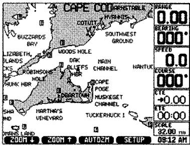
- Press any of the four arrow keys to change the plot to the PAN mode, and to begin moving the cursor to the desired place. Pressing two adjacent keys at once will move the cursor diagonally. The cursor position in lat/lon will be shown.
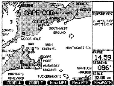
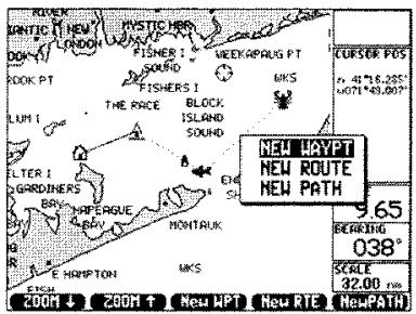
- Enter the cursor position into a new waypoint: to do this, press the [ENT] key, and a window will appear showing the choices NEW WAYPT, NEW ROUTE, NEW PATH. Move the highlight to NEW WAYPOINT with the UP or DOWN keys (if it isn't already there), and press [ENT].
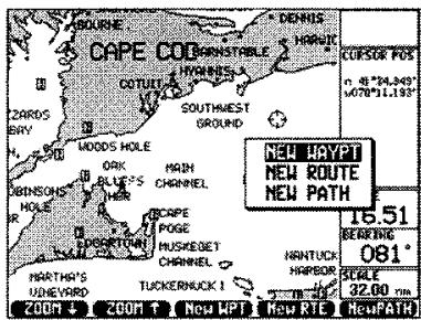
A new waypoint has now been created at the cursor location, with a default name and icon. If you want to change these, display waypoint by pressing [WPT] then press the [UP] or [DOWN] keys to move the highlight to what you want to change, press [ENT], and key in the new name or select the new icon, as previously described in 1.10, screen 9, ENTERING A WAYPOINT.
1.11 SAVING YOUR STARTING POSITION
Before starting your journey to the Edgartown buoy, which is in waypoint BUOY, it's a good idea to save your starting position. Press the SAVE key.
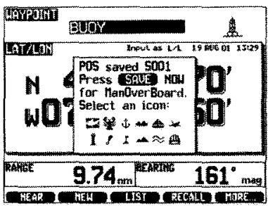
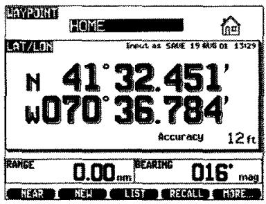
That's all there is to it! Your starting position from Falmouth Harbor is now saved in waypoint S001. (or a similar default name) Let's change the name from S001 to HOME.
- Press [WPT] to bring up the waypoint screen.
- Press RECALL to recall the last saved waypoint.
- Press the UP or DOWN keys to move the highlight to the name field.
- Press [ENT], and then key in the name HOME, just as you entered the name BUOY a few minutes ago.
- Press [ENT] to complete the entry.
1.12 STEERING TO A WAYPOINT
To go to waypoint BUOY:
- Bring up the first waypoint screen by pressing [WPT].
-
Press the LEFT or RIGHT keys a number of times, until waypoint BUOY is displayed.
-
Press the GO TO key. The GPS will now set up a courseline from your present position to waypoint BUOY, and switch to the steering screen.
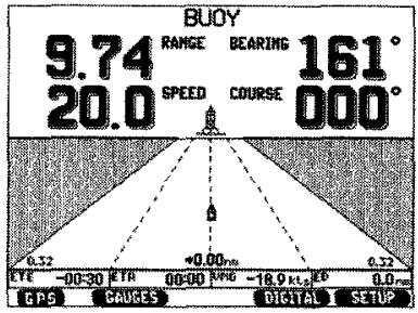
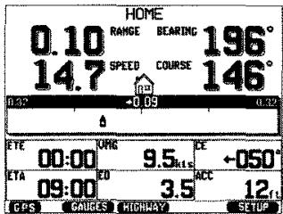
To steer towards a waypoint BUOY, start off on a compass course of about 161 degrees. Steer your vessel to keep the boat icon in the middle of the screen on the center line. This will keep you on a straight line from your starting point at Falmouth Harbor (HOME), to Edgartown buoy (BUOY).
A little while later, the steering screen reads as shown below:
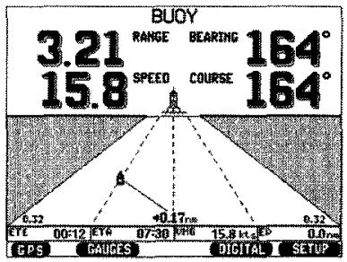
This corresponds to the following situation:
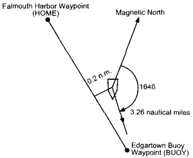
You have drifted about 0.2 miles to the left of the courseline from HOME to BUOY. Steer right to get back on course. The distance to the Edgartown buoy is 3.26 nautical miles.
Keep going until the distance shown is zero, and you will be at BUOY. (Edgartown buoy)
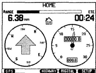
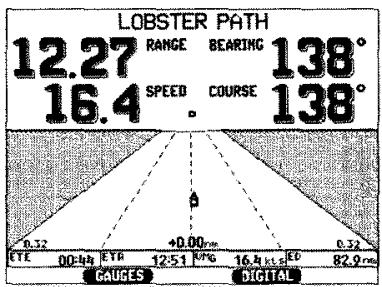
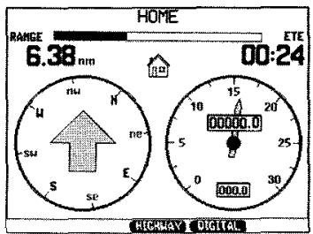
There is another, much simpler steering screen that can be used to steer to a waypoint. While displaying the "highway" steering screen shown above, press the GAUGES key once to get the simple steering screen.
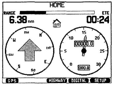
The arrow points toward the waypoint. If the arrow points to the right, turn to the right. If the arrow points to the left, steer to the left. You are on course when the arrow points straight up.
The "arrow" screen also shows the distance to the waypoint, the four major compass directions, and speed over the ground.
1.13 RETURNING HOME
If you remember, you saved your position in waypoint HOME, when you began your journey at Falmouth Harbor. To return home:
- Press [GOTO].
- A list of waypoint names will appear. Press the up or down arrow keys several times to put the highlight on HOME.
- Press [GOTO].
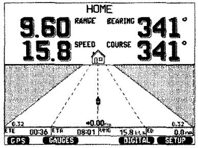
This will set up a courseline from present position to HOME, as shown below.
BASIC OPERATION
2.1 SUMMARY OF BASIC OPERATION
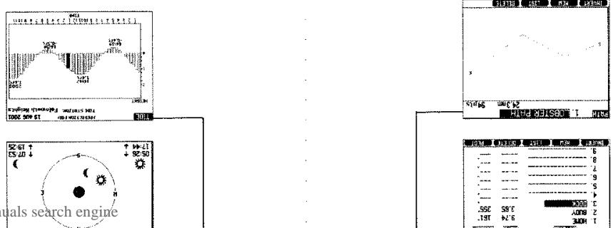
Turn power on by pressing the [PWR*] key. The "ICOM GP-360ML" screen will appear for approximately three seconds, followed by a CAUTION screen. Read the warning, and press [ENT] to acknowledge. Then the SKY PLOT screen will appear until enough satellite signals are found to compute a position fix, then the unit will automatically display the PLOT screen.
THREE SECONDS
CAUTION SCREEN
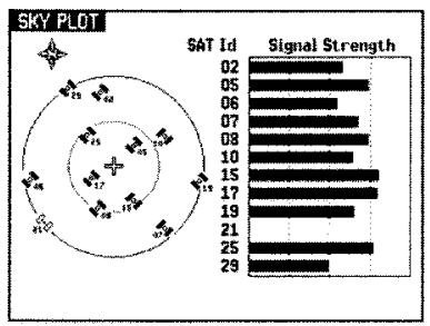
SKY PLOT
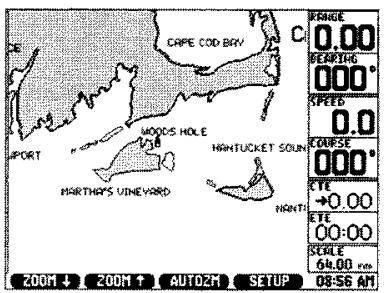
PLOT SCREEN
To save a position, simply press the SAVE/MOB (man overboard) soft key. In an emergency, to mark a man overboard, press the SAVE/MOB soft key twice in quick succession.
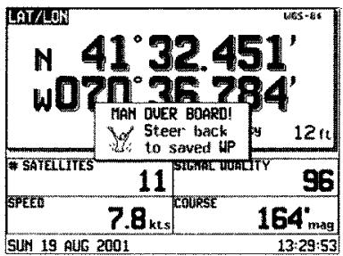
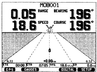
BASIC OPERATION AND DISPLAY SCREENS

Plot Screens
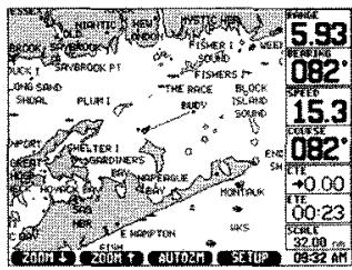
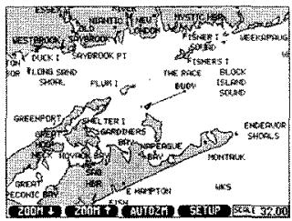

Navigation Screens
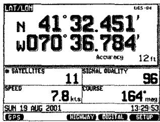
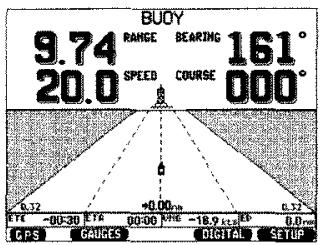

Waypoint Screen
8L
2.2
CUSTOMIZING THE GP-360ML
The operation of the GP-360ML can be customized to suit your needs, in the following ways:
- The coordinates used for input and display of position can be changed.
- The units used for input and display of navigation data can be changed.
- The parameters controlling navigation, steering, plotting, and waypoint navigation can be changed.
- Serial data input and output formats can be specified.
All of these things are controlled through the SETUP lists, which set up the operation of the GPS. All of the SETUP possibilities, and how to use them, are presented in Chapter 8.
If you have some special requirements, or if you want to customize the GP-360ML, read Chapter 8. This will enable you to set up the GPS to best suit your needs.
CHARTS
3.1 ELECTRONIC CHART CARTRIDGES
The ICOM GP-360ML contains a world map showing shorelines. This will give you a rough idea of your position with respect to land, but the level of detail is much lower than the accuracy of the GPS.
To display a more accurate electronic chart, you must insert a Navionics NavChart cartridge. With the NavChart cartridge there will be finer details, with resolution down to a few meters inside ports and marinas. NavChart cartridges are available from your ICOM Dealer, and are available for most areas of the world.
3.2 INSERTING AND REMOVING CARTRIDGES
To open the cartridge chamber door, press inward carefully on the ribbed section of the door to release the catch. The door is located on the lower right hand corner of the GPS. The door will swing down. Insert the cartridge, with the label facing forward aligning the notch and groove Press the cartridge firmly all the way in, and close the door until it clicks shut. If the door strikes the cartridge, the cartridge is not all the way in. To remove a cartridge, grasp the cartridge between your thumb and forefinger and pull it out. If this is difficult, make a tool with a paper clip, insert it into the hole in the bottom of the cartridge, and pull it out with the tool.
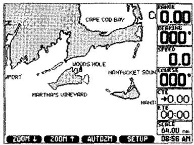
3.3 DISPLAYING A POSITION ON A CHART
You can display your present position on the electronic chart by pressing the [PLOT] key. Water is displayed in white and land is shown in gray.
3.4 ZOOM LEVELS
By pressing the ZOOM UP and ZOOM DOWN keys you can enlarge an area for a more detailed display or wider view respectively. How much detail or how wide an area you can see is a function of your cartridge. The GPS is capable of ZOOM UP as wide as 4096 nm or ZOOM DOWN as small as 0.13 nm.
3.5 AUTO ZOOM FUNCTION
After loading Waypoints, the display may not be set to the best Scale for viewing all of your Waypoints. By pressing the AUTOZM softkey from the PLOT screen, the GP-360ML will automatically zoom to the scale that will best display your Waypoints.
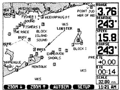
3.6 NAVAGATIONAL AIDS, LIGHTS AND BUOYS
The GPS is capable of displaying the navigational aids (LIGHTS/NAVAIDS) used throughout coastal and inland waterways included in the chart cartridge. A nav aid typically consists of lights, buoys, lighthouses and day beacons. They are drawn on the chart as little boxes surrounding a letter depicting the characteristics of the nav aid.
3.7 CHART DISPLAY SETUPS
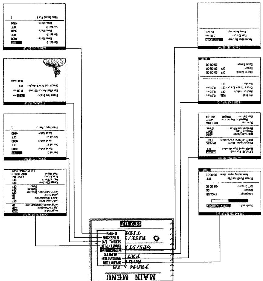
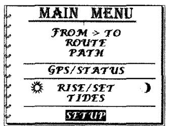
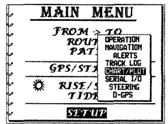
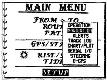
Bring up the CHART/PLOT SETUP screen, and make changes in the setup choices. Press [MENU] to bring up the MAIN MENU. Press the or keys to highlight SETUP and press [ENT]. From the SETUP submenu highlight the CHART/ PLOT field. Press [ENT] to bring up the CHART/PLOT SETUP screen. Using the (up) or (down) keys scroll through the selections. To change one of the setups, highlight the field you want to change and press [ENT].
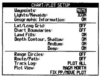
The following choices select what information appears on the plot, and how it appears.
Waypoints - Displays waypoint name, icon... options.
Lights/Navaids - Displays nav aids from chart cartridge as icon or their characteristics.
Geographic Information - Displays names of cities, harbors, channels, etc.
Lat/Long Grid - Displays Lat/Long lines on the chart
Chart Boundaries - Displays rectangular outline of the sub-charts covering areas that contain more chart details.
- Displays land masses as colored gray or just coastlines.
Depth Contour - Displays depth contour lines for shallow, medium, deep water areas.
Range Circles - Displays concentric circle around current position in the radar style to show ranges to nearby waypoints.
Route/Path - Displays current Route or Path options
Track Log - Displays amount of track log on the screen
Plot View
- Default = magn north is the default setting for north. Choices: magn north, true north, from-to up, course up.
- Default = fix pp/ move plot is the default setting for moving map.
Choices: fix pp/ move plot, to show the plot moving around a fixed point; move pp./fix plot to show the point moving through the plot.
WAYPOINTS
4.1 WAYPOINTS
While navigating, it is important to keep track of where you are going and where you have been. It is convenient to keep a list of important or often used locations, such as local buoys and places that you go to frequently.
That is the purpose of the waypoint storage in the GP-360ML - to keep a list of important locations, stored in your GPS.
The GP-360ML has room for 500 waypoints. For each waypoint, there is space for its latitude, longitude, and altitude, a sixteen character name, the date and time it was created, and how it was created.

Note: To have the Altitude displayed, the Altitude Mode in the Navigation Setup must be set to MANUAL.
4.2 CREATING A NEW WAYPOINT
To create a new waypoint:
- Press the [WPT] key to bring up the first waypoint screen.
- Press [NEW] soft key.
- A new waypoint will now be set up with a default name of WPO01, or a similar name. The lat/lon and altitude will be set to your present position, and the highlight will be on the name field.
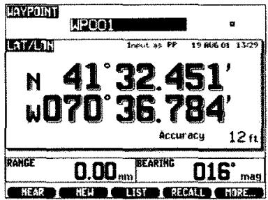
Now enter the following information: As covered on page 9 Section 1.10, ENTERING A WAYPOINT.
a. Name (up to 16 characters)
b. lcon
c. Latitude
d. Longitude
e. Altitude

Note: The Altitude Mode in the Navigational Setup must be set to MANUAL for the Altitude to be displayed.

Note: TO CHANGE A WAYPOINT NAME AFTER THE WAYPOINT HAS BEEN CREATED:
- Display the desired waypoint.
- Press several times, until the highlight is in the name field.
- Press [ENT] to start the name entry.
- Key in the desired name using the keypad.
- Press [ENT] again to complete the name entry.
4.3 DATE AND TIME OF WAYPOINT CREATION
Each time a waypoint is created, all the data you entered for the waypoint is stored in the waypoint memory for future use. In addition to the data you entered, the GPS automatically stores:
1 . The date and local time of waypoint creation
2. The way the waypoint position was entered. The possible ways are:
LL Latitude and Longitude
PP Present Position
RB Range and Bearing from another waypoint
MGRS Military Grid Reference System coordinates
UTM Universal Transverse Mercator coordinates
TDloran TD coordinates
PLOT From the position of crosshairs on the plot.
The method of waypoint creation, and the date and time of creation are shown for each waypoint on the first screen, under it's name.
4.4 FINDING A WAYPOINT
To look up a waypoint by name, press the [WPT] key to bring up the first waypoint screen. Press the LIST soft key to bring up the waypoint list.
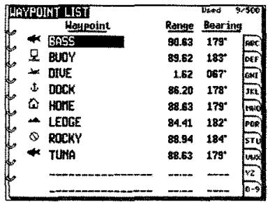
You can now press the or keys to scroll up or down through the alphabetical list of waypoint names. If you have a great many waypoints, you can press to move the highlight to the letter index, the or keys to go the first letter of your waypoint name, and [ENT] to start the list with that letter. If you have several hundred waypoints, this can speed the process.
4.5 THE LIST OF NEAREST WAYPOINTS
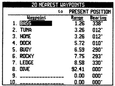
Another way to look up waypoints is to display a list of the 20 waypoints closest to present position, or closest to a specified waypoint.
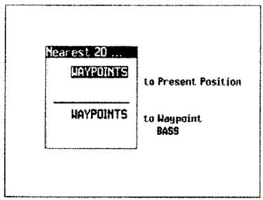
To do this, press the NEAR soft key to bring up the 20 nearest.
Now move the highlight to SELECT WAYPTs NEAREST TO PRESENT POSITION, and press [ENT].
A list of the 20 closest waypoints will come up, arranged in order of proximity, beginning with the closest waypoint
To select one of the waypoints in the list, press or to highlight the desired waypoint. You can then press [ENT] to show the data for that waypoint, or [GOTO], to go to that waypoint.
4.6 GOING TO A WAYPOINT
To go to a waypoint:
A. If the first waypoint screen is displayed:
- Press or to bring up the waypoint you want to go to.
- Press [GOTO].
B. If a waypoint list is displayed on the screen:
- Press or to highlight the waypoint you want to go to.
- Press [GOTO].
C. If neither the first waypoint screen or a waypoint list are displayed:
- Press [GOTO] to bring up the waypoint list. Then follow the instructions in B, above.
4.7 THE SAVE KEY
To save your present position, press the SAVE key. This will create a new waypoint, whose name is automatically assigned to be S001, S002, S003 etc. The number is increased by one each time your position is saved.

A pop up window will appear which tells you that your present position has been saved, and the name of the waypoint in which it was saved. An Icon can now be assigned from that screen, or you can wait until later to assign an Icon or change the name.
The list will be something like S006, S007 and S008. In this example, S008 is the last saved waypoint, S007 is the second to last, etc.
You can also examine the date and time that these waypoints were created, to find a particular saved point.
4.8 MAN OVERBOARD
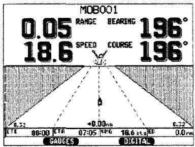
If a person falls overboard, immediately press the SAVE soft key twice in quick succession.
The first press will save your present position, and the second press will set up the steering display to show you how to steer back to the saved position.
4.9 DELETING A WAYPOINT
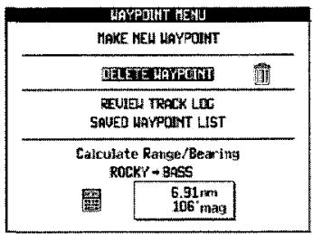
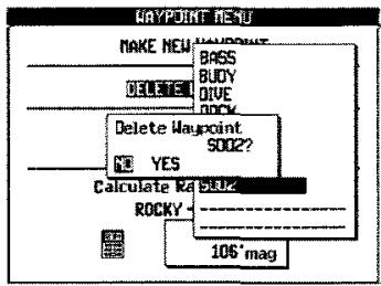
To delete a waypoint:
- Press [WPT] to bring up the first waypoint screen.
- Press the MORE soft key.
- A new screen will appear. Press to move the highlight to DELETE WAYPOINT, and press [ENT].
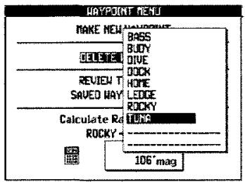
- A window with a waypoint list will appear. Press or to highlight the desired waypoint, and press [ENT].
- A window will appear, asking if you want to delete that waypoint. Press or to select YES, and press [ENT].
4.10 DELETING ALL WAYPOINTS
To delete all waypoints:
- Go to [MENU] and scroll down and highlight SETUP and press [ENT].
- Scroll up or down to OPERATION and press [ENT].
- Press the [MORE] soft key and scroll down to ERASE ALL WAYPOINTS & ROUTES and press [ENT].
- A new window will appear asking you to confirm "Erase All Waypoints & Routs?" Select YES and press [ENT] to confirm.
4.11 RANGE AND BEARING FROM ONE WAYPOINT TO ANOTHER
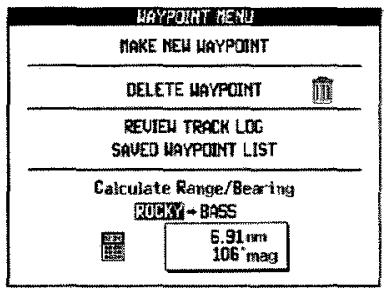
- Press [WPT] to bring up the first waypoint screen.
- Press the MORE soft key.
- The bottom portion of the screen shows CALCULATE RANGE/ BEARING and below a FROM and a TO waypoint. Press to highlight the FROM field, and press [ENT].
- Press or to select the desired FROM waypoint, and press [ENT].
- Press to move the highlight to the TO field, then press [ENT]. Press or to select the desired TO waypoint, and then press [ENT].
The display will now show the range and bearing from one waypoint to another. Setting up this screen does not change the FROM and TO waypoints used for navigation.
4.12 OTHER METHODS OF CREATING WAYPOINTS
To create waypoints using MGRS, UTM, or Loran TD coordinates, the SETUP controls that enable the GP-360ML to use these coordinate systems must be turned ON. The procedure for doing this is given in Section 8.2.
To create waypoints by methods other than Lat/Lon:
- Press [WPT] to bring up the first waypoint screen.
- Press the MORE soft key.
- Press to highlight MAKE NEW WAYPOINT. Press [ENT].
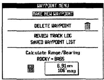
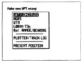
- Press or to highlight the desired method of waypoint creation, and press [ENT]. This will bring up a display screen showing the coordinates and information required for each method of creation.
TRACK PLOTTING
5.1 AUTOMATIC POSITION RECORDING
The GP-360ML periodically records its position, along with the date and time of the recording, and the position fix accuracy.
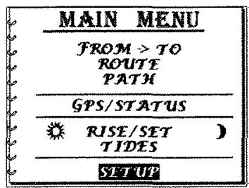
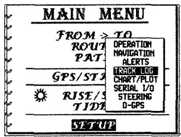
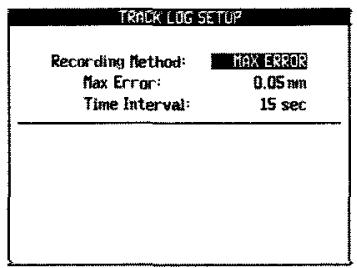
The recorded track is the sequence of recorded points, connected by straight lines. The recording can be done so that the maximum error in the recorded track is kept below a specified value, or it can be done at equal time intervals. The default setting is to limit the maximum error in the recorded track to 0.05 nautical miles (92 meters) The controls for the data recording can be found under MENU, SETUP, TRACK LOG SETUP. The recording takes place only when the GPS has a good position fix (ACC less than 2000 feet).
There is space for 500 points of recorded data. After 500 points are recorded, each new point will be recorded over the oldest point, which is lost. The memory always contains the last 500 points recorded.
Thus you can go back and look at where you've been, even if you haven't saved any waypoints or written down any of the position fixes computed by the GPS.
5.2 PLOT OF PREVIOUS TRACK
The plot of the previous track, ending in present position, can be displayed by pressing the [PLOT] key. Some numerical data is shown on the screen. The plot area can be made larger by pressing the [PLOT] key again, which will cause the numerical data area to be dropped.
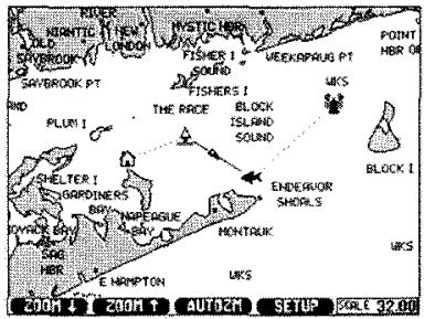
The plot scale (size of the plotted area) can be changed by zooming in or out.
To center the plot, press PLOT soft key. This will center the plot to best show the FROM waypoint, the TO waypoint, and present position.
The plot scale can be increased or decreased by pressing the ZOOM UP ▲ or ZOOM DOWN ▼ soft keys, as indicated in the bottom portion of the screen. This is called Zooming out or Zooming in.
To move the viewing area, press the or A set of crosshairs will appear, to show that you are in the pan mode. The four arrow keys can be used to pan, or move the plot area up, down, right, or left.
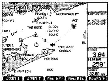
While in the pan mode, you can identify any waypoint, light, or stored track points that are in the plot. To do this, pan the crosshairs to the point of interest. As soon as the crosshairs are on a point, the point position, name and other data will immediately be displayed in the numerical data area on the screen.
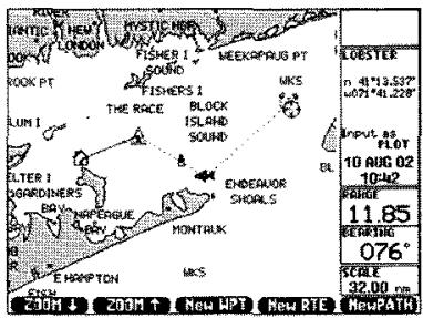
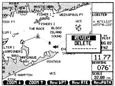
While in the pan mode, if [ENT] is pressed, a menu will appear that will enable you to make a new waypoint from the position of the crosshairs. It will also enable you to make a new path or new route from the plot, or to zoom in and out.
To exit the pan mode, press the [PLOT] key.
5.3 USING THE PREVIOUS TRACK TO RETURN HOME
Suppose that you have been on a trip, and want to return home, going back the way you came. The plot of previous track can always be used to do this, even if you haven't saved any waypoints.
Simply press the [PLOT] key, and head back the way you came. The Plot screen will be shown as MAG NORTH UP, unless it has been changed from the default setting. (TRUE NORTH UP or FROM-TO UP or COURSE UP can also be selected in the PLOT SETUP menu.)
Now steer to stay close to the track you came in on, adjusting the zoom with the ZOOM IN and ZOOM OUT soft keys to make the plot most convenient for steering.
Steering is generally easier, if the plot is changed to FROM-TO UP, or COURSE UP.
5.4 STORING AND DISPLAYING PATHS
Sections of the automatically recorded track can be picked out and stored permanently as paths. There is space for ten paths in the GP-360ML, and up to a maximum of 500 points.
To store a path:
- Press MENU to display the menu screen.
- Press to highlight the PATH field. Press [ENT].
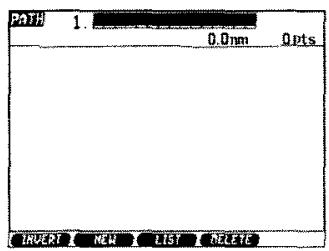
- Press NEW soft key.
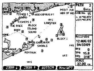
- Press a number of times, to step the cursor back along the recorded track, to the point which is to begin the path. Press [ENT] to start the path at that point.
- Press or a number of times, to move the cursor along the recorded track, and to add points to the path.
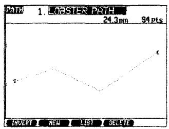
- Press [ENT] to end the path recording. A name can now be entered to identify the path.
5.5 FOLLOWING A PATH
To follow a path:
- Press [MENU] to display the Menu screen.
- Press or several times to highlight the PATH field. Press [ENT].
- Press the LIST soft key.
- Use the or key to highlight the desired path name, and press [ENT] to bring up the data screen for that path.
- To set up a courseline to the closest point in the path, press [GOTO]. When you pass that Path point, the destination will automatically be switched to the next point along the Path, until the end is reached. The crosstrack error shown in the second NAV screen and output to the autopilot will be your distance off the Path.
RUTES
6.1 COURSELINEs, LEGS, AND ROUTES
A courseline is the line between two waypoints, along which you intend to travel. A leg is the same thing, a line joining two waypoints. A route is a number of legs connected together.
| ROUTE 1. HOME-DOCK | |||
| 27.0mm | 6pts | ||
| Veupoint | Range | Bearing | |
| 1. HOME | 6.11 | 356* | |
| 2. DIVE | 4.87 | 247* | |
| 3. LEDGE | 5.47 | 200* | |
| 4. BUDY | 5.81 | 101* | |
| 5. BASS | 4.70 | 018* | |
| 6. DOCK | - | - | |
| 7. | - | - | |
| 8. | - | - | |
| 9. | - | - | |
| THUCTRET HEL List DELETE PLOT | |||
The above route goes from waypoint 1 to waypoint 6, and consists of 5 legs.
6.2 PRESENT COURSELINE
Your present courseline (or leg) can always be seen on the FROM TO screen. To bring up this screen, press [MENU], scroll to FROM TO and press [ENT].
| BUOY ↓ HOME | |
| RANGE BEARING | 6.92 nm 082° mag |
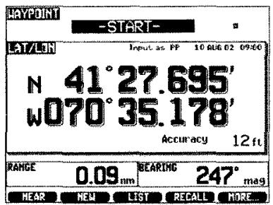
The display will always show the FROM and TO waypoint identification, and the range and bearing of the leg. Quite often, the FROM waypoint will not be a waypoint you have created, and put in the waypoint list. It will often be your position at the time you started on the leg. In this case, the FROM waypoint will be called START. The START waypoint is not kept in long term memory. It will be overwritten with a new location, every time you press [GOTO]. If you are on an active route, the route and leg information will be shown at the bottom of the screen.
6.3 ROUTE NAVIGATION
The route function allows you to set up and follow a sequence of waypoints. Once the sequence is set up, it is kept in memory, and available for use at any time. The sequence of waypoints is called a route.
A route can contain up to 50 waypoints, and the GP-360ML can store up to 50 routes.
6.4 CREATING A ROUTE
A route can be created in two ways. It can be done by selecting a sequence of waypoints in the waypoint list, or by selecting a sequence of points in a plot.
To create a route from the waypoint list:
- Press [MENU] to bring up the Menu screen.
- Use the and keys to highlight ROUTE, and then press [ENT]. This will bring up the Route screen.
- Press NEW. Use the arrow key to highlight the field for the first waypoint in the route. You are now ready to enter the sequence of waypoints that will make up the route.
- To begin the waypoint selection, press [ENT]. This will bring up a list of waypoints, in alphabetical order.
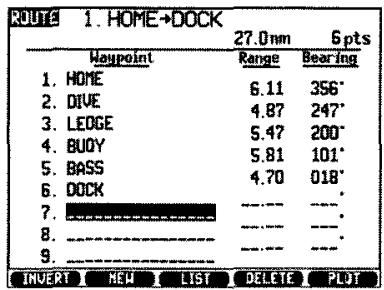
- Press and a number to times to highlight the waypoint you want to be next in the route. Then press [ENT] to make the selection. The waypoint will be entered in the route, and the highlight will move to the next waypoint field.
- Repeat steps 4 and 5 to add another waypoint to the route.
The route will be given a default name including the first and last waypoint names, such as HOME EDGAR. The route screen will show the number of waypoints in the route, and the total length of the route.
To create a route from a plot, press the PLOT soft key at the bottom of the screen.
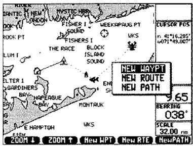
- Press NEW RTE soft key.
- Press the four arrow keys to move the crosshairs to the first desired route point. If you want that point to be an existing waypoint or light, move the crosshairs to that point, until they "snap" to the point, and the waypoint or light data appear at the top of the screen.
- Press [ENT] to bring up a sub-menu. Highlight INSERT, and press [ENT]. This will make the crosshairs location the first point in the new route.
- Press the four arrow keys to move the crosshairs to the next desired route point, as in step 5 on the previous screen.
- Press [ENT] to bring up the sub-menu. Highlight INSERT, and press [ENT] to add the point to your route.
- Repeat steps 4 and 5 to add more points to the route.
6.5 FOLLOWING A ROUTE
- Bring up the Route screen, by pressing [MENU], highlighting ROUTE, and pressing [ENT].
- If the Route shown is not the one you want, press or several times until the desired Route is displayed.
- Check the direction of the route, which is going from the first to last waypoint shown. If you want to go in the opposite direction, press INVERT soft key. This will invert the route.
- Press the [GOTO] key.
The Route is now activated, and the first leg will be from your present position to the route point closest to where you're starting from. When you pass each waypoint, the destination will automatically switch to the next waypoint along the Route.
6.6 EDITING AND DELETING ROUTES
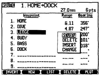
A route can be edited at any time, by highlighting a waypoint in the route, and pressing [ENT]. A menu will appear, that will allow you to highlight one of the following choices:
REVIEW Press [ENT] to review waypoint data.
DELETE Press [ENT] to delete the waypoint from the Route.
INSERT Press [ENT] to bring up a waypoint list. Highlight a waypoint in the list, and press [ENT] to insert the waypoint before the previously highlighted Route point.
CHANGE Press [ENT] to bring up a waypoint list. Highlight a waypoint in the list, and press [ENT] to insert the waypoint in place of the previously highlighted Route point.
SUNRISE, SUNSET AND TIDES
7.1 SUNRISE AND SUNSET
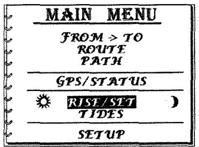
Press [MENU], and then press the key to move the highlight to the RISE/SET field. Press [ENT] to bring up the SUN RISE/SET MOON screen.
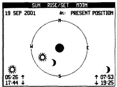
The sun and moon data are for the date and position shown at the top of the screen. The default values are the present date and position. It is possible to key in another date, and select a waypoint instead of present position. In this way, the sun and moon display can be seen for any point on Earth, and any date (within 30 years of 1996).
The local times for rise and set of the sun and moon are shown at the bottom of the screen.
The clock at the center of the screen will step one hour each second, and the positions of the sun and moon are shown on the celestial hemisphere for every hour of the day. The clock will be dark to indicate pm. Up (the top of the circle) is true north.
7.2 24 HOUR TIDE PREDICTION
Press MENU, and then press the key several times to highlight the TIDES field. Press [ENT] to bring up the 24 HR TIDE PLOT screen.
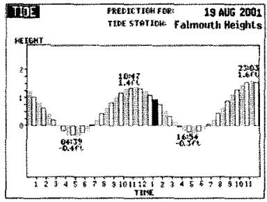
The tide plot is a prediction for the date and position shown at the top of the screen. The default values are the present date and position. It is possible to key in another date, and select a waypoint instead of present position. In this way, the tide prediction can be seen for any point on Earth, and any date (within 30 years of 1996).
The plot shown is the predicted level of the free ocean tide (without the influence of land) over a 24 hour period. The plot shows the tide height, relative to the highest tides possible, which are when the sun and moon are aligned on one side of the Earth.
The shape of the tide plot will generally be accurate, and the times of high and low tides will generally be accurate to within a half hour. The actual tide height is affected by the shape of the local ocean floor, and can change considerably over a few miles along a coast. The tide height is also affected by wind and weather.
The tide prediction used by the GPS does not take these things into account, and does not predict the actual height of the tide on a seacoast. It does show the general shape of the tide, its height relative to the highest possible tide, and the times of high and low tide.
CUSTOMIZING SETUP CHOICES
There are a large number of choices that can be made, to customize the operation of the GP-360ML. All of these choices are explained in this chapter.
8.1 OPERATION SETUP
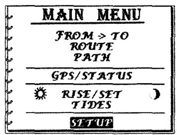
Press MENU to bring up the MAIN MENU. Press the or keys to highlight SETUP, and press [ENT]. The SETUP submenu will be shown, highlight OPERATION field. Press [ENT] to bring up the OPERATION SETUP screen.
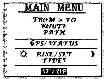
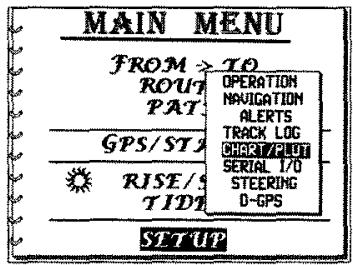
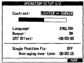
A number of operation setup choices are now shown. To change one of the operation setup:
- Use the or keys to highlight the field you want to change, and press [ENT].
- Use the keys to step through all of the choices available. When you get to the selection you want, press [ENT] to make that selection.
When the field to be changed is a numerical field, use the number keys to key in the number you want, and press [ENT], just as in any number entry.
The Operation Setup occupy two screens. To bring up the second screen, press the MORE soft key.
The following are the operation setup that can be selected, and the choices available. To make the choices, highlight the field to be changed.
SCREEN CONTRAST - Use the and keys to adjust the screen contrast. Move it across the full range, and leave it where the screen looks the best.
LANGUAGE - Default = English. Choices: English, Spanish, French, German, Italian. . .
The language used in the major display screens can be selected. Display screens that are rarely used are always in English.
BEEPER - Default = ON. Choices: ON, OFF
The beeper can be turned off, if for some reason you want silent operation.
GMT OFFSET - Default = various. Choices: -12:00:00 to +12:00:00
Normally, local time is set by keying approximate time into the first NAV screen. GMT offset is then automatically computed to the nearest half hour, which will account for all hour and half hour time zones. If you are in a time zone offset from GMT by a time that is not hours or half hours, you can key in any offset here. If you do this, don't key in local time into the first NAV screen, or the offset you keyed in here will be lost.
Example: You are in Saudi Arabia, where the local time is offset minus two hours and forty-five minutes from Greenwich time. Key -2:45:00 into GMT offset, and you will display the correct local time.
SINGLE FIX MODE - Default = OFF. Choices: ON, OFF, ONCE
The single fix mode is used to average your position over a period of time, and store the averaged position in a waypoint. To use it, set SINGLE FIX to ON, and key in the desired averaging time.
AVERAGE - Default = 15 seconds. Choices: 1 to 99,999 seconds (one day is 86,400 seconds).
Each time the GP-360ML is turned on, as soon as it has a good position fix, it will start averaging the position. When it has averaged for the specified time, it will store the averaged position in the save list, just as if you had pressed the SAVE key. The position can then be found as the last saved position.
Press the MORE soft key and press [ENT], to bring up the second screen of Operation Setup.
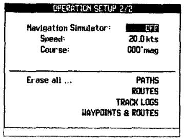
NAV SIMULATOR MODE - Default = OFF. Choices: OFF, AUTO STEER, MANU STEER, PAUSE
When the simulator is not OFF, the system lat/lon are not updated from the GPS signals. Desired initial lat/lon can be keyed into the first NAV screen. With AUTO STEER, the simulated position will move toward the TO waypoint, at the SPEED you have input. With MANU STEER, the simulated position will move at the input SPEED and COURSE. With PAUSE, the NAV screens will show the input SPEED and COURSE, but position will not move.
SPEED - Default = 0.0 knots. Choices: 0.0 to 999.9 knots
COURSE - Default = 0 degrees. Choices: 0 to 359 degrees
The simulator can be used to set up navigation examples, so that you can use all the screens just as if you were traveling. It can be used to practice navigation, and to become familiar with all of the capabilities of the GP-360ML.
ERASE PATHS, ROUTES, WAYPOINTS AND ROUTES - Selecting this choice will enable you to erase all of the paths, routes and waypoints in the GPS.
8.2 NAVIGATION SETUP
Bring up the NAVIGATION SETUP screen, and make changes in the setup choices. Use the or keys to scroll through the selections. To change one of the setups, highlight the field you want to change and press [ENT].
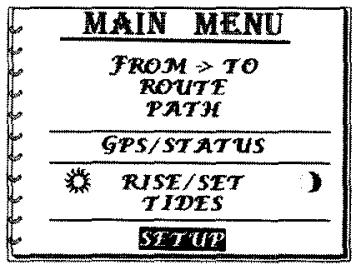
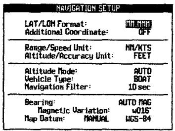
The available choices are:
$$ \begin{array}{l} \text {L / L F O R M A T - D e f a u l t = M M . M M M ^ {\prime} . C h o i c e s : M M . M M M ^ {\prime} o r} \ \text {M M ^ {\prime} S S . S} \end{array} $$
The choice of minutes and thousandths of minutes, or minutes, seconds, and tenths of seconds affects all position display, key entry, or serial data input and output.
$$ \begin{array}{l} \text {A D D I T I O N A L C O O R D - D e f a u l t = O F F . C h o i c e s : O F F L o r a n , U T M ,} \ \text {M G R S , O S G B} \end{array} $$
If another coordinate system is chosen, that coordinate system and lat/lon will be displayed on successive screens, by repeatedly pressing the NAV key.. Waypoints can be input or displayed in the additional coordinates. MGRS, UTM, and LORAN coordinates are described in Appendices B and C.
$$ \begin{array}{l} \text {R N G / S P D U N I T S - D e f a u l t = n m / k t s . C h o i c e s : n m / k t s , m i / m p h ,} \ \text {k m / k p h} \end{array} $$
$$ A L T / A C C U N I T S - D e f a u l t = f e e t. C h o i c e s: f e e t, m e t e r s $$
$$ A L T M O D E - D e f a u l t = m a n u a l. C h o i c e s: m a n u a l, a t o $$
In the manual mode, the altitude is input into the first NAV screen, and is never changed. In the auto mode, it is computed whenever it is available for navigation.
For a boat operating at a fixed altitude, the computed lat/lon are slightly more stable and accurate if the ALT MODE is manual.
$$ V E H I C L E - D e f a u l t = b o a t. C h o i c e s: b o a t, c a r, a i r c r a f t, w a l k $$
The vehicle choice is used to estimate how fast the altitude is likely to be changing, when operated in the auto ALT MODE.
$$ \text {N A V F I L T E R} - \text {D e f a u l t} = 1 0 \text {s e c o n d s . C h o i c e s :} 1 - 2 5 5 \text {s e c o n d s} $$
The nav filter is used to filter the computed speed and course. For a powerboat, 5 seconds of filtering will normally give the best results. For a sailboat, a filter time of 20 seconds is better. If the filter time is too short, the display of speed and course will be jumpy. If it is too long, the screens will be slow to respond to a maneuver, and will lag behind what the boat is doing.
BEARING - Default = auto mag. Choices: manual mag, auto mag, true north
The displayed courses and bearings include magnetic variation, if manual mag or auto mag are chosen. With auto mag, the variation is computed based on your lat/lon, and is generally accurate to one degree anywhere on earth (with the exception of very near the magnetic pole). With manual mag, the variation is keyed into the VARIATION field.
VARIATION - Default (computed automatically).
Key in the variation only if BEARING is set to manual mag.
MAP DATUM - Default = Manual. Choices: manual, auto
If auto is selected, the datum is automatically selected from the 12 most common datums, based on position. AUTO is only appropriate for land navigation.
DATUM - Default = WGS-84. Choices: 134 choices, including USER INPUT
For marine use, WGS-84 is used for almost all charts. Map datum are a complex subject, described in Appendix E.
8.3 ALERT SETUP
Bring up the ALERTS SETUP screen, and make changes in the setup choices, in a manner similar to that described in the beginning of Section 8.1. The available choices are:
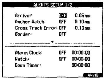
WAYPOINT ARRIVAL - Default = OFF. Choices: OFF, ON
RANGE - Default = 0.05 nm. Choices: 0.01 nm to 99.99 nm
When WAYPOINT ARRIVAL is ON, and your vessel comes within RANGE of the TO waypoint, or passes the TO waypoint, audio and visual alerts will be given. The alert is cancelled when the [ENT] key is pressed.
ANCHOR - Default = OFF. Choices: ON, OFF
RANGE - Default = 0.1 nautical miles. Choices: 0.01 nm to 99.9 nm
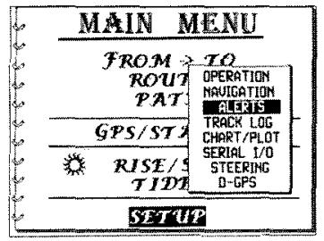
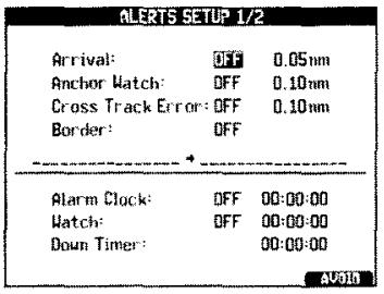
After your vessel has anchored, and come to a steady position, set ANCHOR to ON. Your vessel's position will be saved, and an alert will be given if you drift away from the anchor point, more than the allowed range. Note that setting the RANGE less than 0.10 nm is likely to result in false alarms, as the position indicated by the GPS can shift by as much as 0.15 miles over a period of time, even if you are not moving.
CROSSTRACK ERROR - Default = OFF. Choices: ON, OFF
RANGE - Default = 0.10 nm. Choices: 0.01 to 9.99 nm
When the cross track error alert is ON, an alert will be given if the cross track error magnitude exceeds the RANGE number.
BORDER - Default = OFF. Choices: OFF, LEFT, RIGHT
FROM WAYPOINT - TO WAYPOINT
To use the border alert, put the two end points of the border into the GPS, as two waypoints. Specify them as the FROM WAYPOINT and TO WAYPOINT. Enter the alert distance from the border into the cross track alert range. For example, if you want an alarm when you get within a half mile of the border, enter -0.50 into the crosstrack alert range. Now set BORDER to ON, and the border alert will be active.
CLOCK - Default = OFF. Choices: ON, OFF
Time - Default = 00:00:00, Choices: 00:00:00 to 23:59:59
This is the alarm clock alert. At the specified time when the ALARM CLOCK is ON, an alarm will sound. A visual alert will also be given, which can be cancelled with the [ENT] key.
WATCH - Default = OFF. Choices: ON, OFF
Time - Default = 00:00:00. Choices: 00:00:00 to 11:59:59
This is the watch alert. When it is ON, an internal watch timer starts from zero, and counts up. When it reaches the watch time, an alert is sounded. When [ENT] is pressed, the watch timer resets to zero, and the process is repeated. The watch time is typically set to 5 or 10 minutes, and the need to periodically clear the alert will make sure the person on watch does not go to sleep.
DOWN TIMER - Default = OFF. Choices: ON, OFF
Time - Default = 00:00:00. Choices: 00:00:00 to 23:59:59
The DOWN TIMER is also called the yacht racing timer. It is typically set to 00:10:00, and turned ON exactly 10 minutes before a race. The timer will begin counting down, and will give 5 one second beeps with 5 minutes to go, 4 beeps with 4 minutes to go, etc. When it reaches zero, it will give one 5 second beep, and shut itself off.
AVOID - Default = OFF. Choices: ON, OFF
To set up and operate the avoid alert, press the AVOID soft key at the bottom of the screen. This will bring up an AVOID screen, which shows 10 waypoints, each with its own reference range.
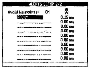
To use the avoid alert, put the coordinates of places you want to avoid (such as a barely submerged rock) into waypoints, and put the waypoint names into the AVOID list. After each waypoint name, enter the range from the avoid point, where you want to be given an alarm.
After AVOID is turned ON, if you should get closer to any of the avoid points than its avoid range, an alarm will sound, and the screen will give instructions on how to cancel the alarm.
8.4 TRACK LOG SETUP
Bring up the TRACK SETUP screen, and make changes in the setup choices, in a manner similar to that described in the beginning of Section 8.1. The available choices are:
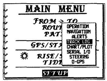
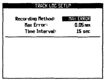
RECORD TRACK BY - Default = limit max track error. Choices: limit max track error, time interval
LIMIT MAX TRACK ERROR - Default = 0.05 nm. Choices: 0.01 to 1.00 nm
TIME INTERVAL - Default = 00:01:00. Choices: 00:00:01 to 01:00:00
If the track points are recorded to limit max track error, the recorded track points connected with straight lines will always be within the error tolerance of the actual track of the boat. If the boat travels along straight lines, this is very efficient, as only a few recorded points are necessary.
The track points can also be recorded at equal time intervals.
Track points will be recorded only if the GPS position fix is good (the accuracy number is less than 2000 feet).
8.5 SERIALI/OSETUP
The setup of the serial input and output ports is normally done by an electronics technician, and involves some complicated choices. This is described in Appendix H.
8.6 STEERING SETUP
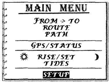
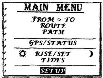
Press MENU to bring up the MAIN MENU. Press the or keys to highlight SETUP, and press [ENT]. The SETUP submenu will be shown. Use the or keys to highlight STEERING. Press [ENT], to bring up the STEERING SETUP screen.
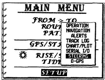
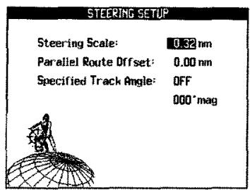
STEERING SCALE - Default = 0.32 nm. Choices: 00.02 to 99.99 nm
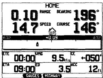
The steering scale limits the maximum cross track error that can be shown on the "highway" steering screen (second NAV screen).
PARALLEL ROUTE OFFSET - Default = 0.00 nm. Choices: 00.00 to 99.99 nm
If parallel route offset is set to 0.20, then crosstrack error will be zero along a line 0.20 nautical miles to the right of the courseline from the FROM to the TO waypoints. In other words, your course is offset 0.20 miles to the right.
SPECIFIED TRK ANGLE - Default = off. 000^ mag, Choices: ON, OFF, 000^ to 359^ mag
When the specified track angle is ON, then crosstrack error then becomes the perpendicular distance away from a line going through the TO waypoint at the specified magnetic bearing. Steering to drive the crosstrack error to zero will then take the vessel to the TO waypoint, at the specified track (bearing) angle.
While in one of the NAV steering screens, you can select the main HIGHWAY, GAUGES or DIGITAL steering screens by pressing the corresponding soft key located at the bottom of these screens.
GLOSSARY
ACC Accuracy - The expected Accuracy of a position Fix.
ALMANAC The approximate description of the orbits of all of the GPS satellites. This is received periodically from each satellite.
BEARING The angle between the direction to north, and the direction to another point. Bearings can be true or magnetic.
CE Course Error - The difference in degrees from your Track to your actual course
CONSTELLATION All of the GPS satellites, about 24 in number.
COORDINATE A number, typically about 7 digits long. (One of a pair of numbers, which define position.)
COORDINATE PAIR Two numbers,which define a position,or waypoint.
COURSE The angle from north to the direction you are traveling. Course can be true or magnetic. Note that this is not the same as heading. Course is sometimes called Course-Over-The-Ground.
COURSELINE The line from the waypoint you're coming FROM to the waypoint you're going TO. It marks the course you're supposed to be on.
CROSSTRACK ERROR The distance you are off your courseline. (CTE)
ED Elapsed Distance - The Distance traveled from your starting Point to your present position.
| EPHEMERIS | The exact description of the orbit of one of the satellites, which is necessary to use the satellite for navigation. A GPS receiver gets the ephemeris by receiving signals from the satellite. (Plural, ephemerides) |
| ETE | Estimated Time Enroute – The Estimated time it will take to travel from a Starting point to a Waypoint, based on the speed you are traveling. |
| GPS | The Global Positioning System, which consists of 24 satellites circling the Earth, transmitting radio signals which can be used to compute position, speed, and course. |
| HEADING | The direction between north, and the direction the bow of your boat is pointing. Heading can be true or magnetic. |
| LAT/LON | Short for latitude and longitude, the coordinate system used for most marine navigation. |
| LEG | The line from one waypoint to another. |
| LORAN | A navigation system dating from 1957, using land based transmitters of 1000 mile range, and covering much of the settled coastal areas of the northern hemisphere. |
| MAGNETIC NORTH | The direction toward the north magnetic pole. This is the direction the needle of a magnetic points toward. |
| MAGNETIC VARIATION | The angular difference between true north and magnetic north. Magnetic bearing is the true bearing plus the variation, if the variation is west. If the variation is east, it is minus the variation. |
| MAP DATUMS (DATUMS) | Map datum are the devices used to assign latitude/longitude, values to positions on the earths surface. There are more then one map datum. |
MGRS
Military Grid Reference System, the coordinate system used for most modern land charts.
ROUTE
A path going from a starting waypoint to an ending waypoint, formed from a number of legs joined together.
SELECTIVE AVAILABILITY (SA)
A U. S. Government policy whereby the GPS navigation signals provided for civil use are deliberately made less accurate than those provided for military use. The degree of accuracy can be changed at will by the government.
TIME TO GO
The time it will take to reach your (TTG) destination, or TO waypoint.
TD
Time Differences, the coordinate system used by LORAN receivers, and on LORAN charts.
TRUE NORTH
The direction toward the north pole, shown as up on most navigation charts.
UTM
Universal Transverse Mercator, a coordinate system used on some land charts.
VMG
Velocity Made Good is a measure of how fast the boat is currently traveling towards the finishing point.
MGRS AND UTM COORDINATES
The GP-360ML GPS can be used with Military Grid Reference System (MGRS) and Universal Transverse Mercator (UTM) coordinates. These coordinate systems are used for land navigation and charting. The GPS will display present position and waypoint position in these coordinates. Waypoints can also be input in MGRS and UTM coordinates.
In order to use MGRS or UTM coordinates, the setup item Additional COORD must be set to MGRS or UTM. This setup item is in the NAVIGATION SETUP screen, accessed by MENU, SETUPS, NAVIGATION.
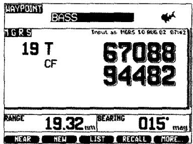
When Additional COORD is set to MGRS, additional screens showing MGRS coordinates will appear under the [NAV] and [WPT] keys.
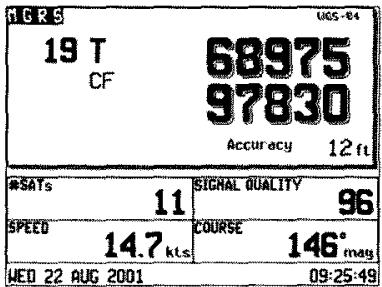
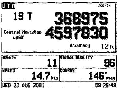
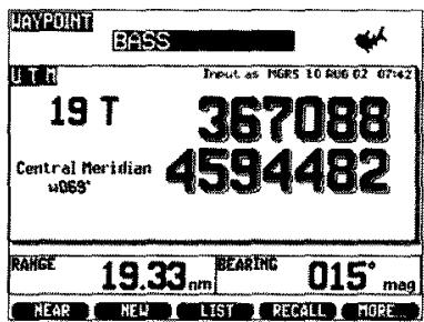
When Additional COORD is set to UTM, additional screens showing UTM coordinates will appear under the [NAV] and [WPT] keys.
Creating a Waypoint in MGRS Coordinates
To create a waypoint in MGRS coordinates, perform the following steps:
-
Set the setup item Additional COORD (in the NAVIGATION SETUP screen) to MGRS.
-
Read the bottom margin of the chart you are using, and find the map datum that was used to make the chart. Set the GPS to the same map datum. Instructions for doing this are given in Appendix D.
- Press the [WPT] key several times, until the MGRS screen comes up.
- Press the NEW soft key.
- Key in the waypoint name, just as when creating a waypoint in lat/lon.
- Key in the desired MGRS coordinates. For example:
Grid Zone 11 S
100,000 meter square designator LT
Easting 52
Northing 89656 meters
Any waypoint can be viewed in MGRS coordinates, regardless of how the waypoint was created. To do this, do steps 1-3, and use the and keys to step through the waypoint list.

Creating a Waypoint in UTM Coordinates
To create a waypoint in UTM coordinates:
- Set the setup item Additional COORD (in the NAVIGATION SETUP screen) to UTM.
- Read the bottom margin of the chart you are using, and find the map datum that was used to make the chart. Set the GPS to the same map datum. Instructions for doing this are given in Appendix D.
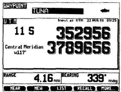
- Press the [WPT] key several times, until the UTM screen comes up.
- Press the NEW soft key.
- Key in the waypoint name, just as when creating a waypoint in lat/lon.
- Key in the desired UTM coordinates. For example:
Grid Zone
11 S
Easting
352956 meters
Northing
3789656 meters
The Grid Zone is used to automatically compute the Central Meridian. (The Central Meridian cannot be input manually.)
Any waypoint can be viewed in UTM coordinates, regardless of how the waypoint was created. To do this, do steps 1-3, and use the and keys to step through the waypoint list.
LORAN C COORDINATES
The GP-360ML GPS can be used with LORAN TD coordinates. This coordinate system is found on many marine charts, and has been extensively used to record the location of shipwrecks, underwater hangs, and fishing spots. The GPS will display present position and waypoint position in these coordinates. Waypoints can also be input in LORAN TD coordinates.
In order to use LORAN TD coordinates, the setup item OTHER COORD in the NAVIGATION SETUP screen must be set to LORAN.
When OTHER COORD is set to LORAN, additional screens showing LORAN TD coordinates will appear under the [NAV] and [WPT] keys.
Creating a Waypoint in LORAN Coordinates
If you usually use latitude and longitude, you might think to yourself "What am I going to use LORAN TDs for?" Well imagine you've invited some friends to go fishing, and one of them, crafty old fisherman that he is, has brought along his black book of never fail fishing locations. The only problem is, they're all in TDs, since they were gathered long before the age of satellite navigation. With the GP-360ML, you can enter them directly into a waypoint and go directly there.
The truth is, you can go close to there. The GPS measurement of position converted to TDs doesn't have the landpath errors of the LORAN system of navigation, so the point you go to will not be exactly the same as with a LORAN. You can expect a hundred yards of error, or more if the LORAN geometry is not good.
To create a waypoint in LORAN coordinates, perform the following steps:
- Set the setup item OTHER COORD (in the NAVIGATION SETUP screen) to LORAN.
-
Make sure the map datum is set to WGS-84, which is used for essentially all marine charts.
-
Press the [WPT] key several times, until the LORAN screen comes up.
- Press the NEW soft key.
- Key in the waypoint name, just as when creating a waypoint in lat/lon.
- Key in the desired LORAN coordinates. For example:
GRI
9960
TD1
16255.82 microseconds
TD2
27480.21 microseconds
Any waypoint can be viewed in LORAN coordinates, regardless of how the waypoint was created. To do this, do steps 1-3, and use the and keys to step through the waypoint list.
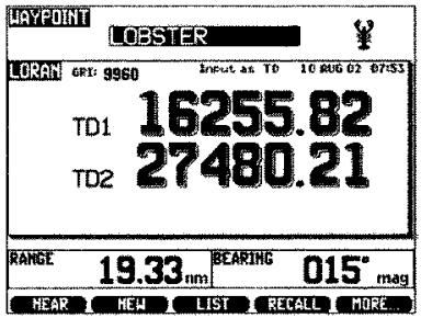
After the second TD is entered, the navigator will automatically convert the TD pair to latitude and longitude, and store it in memory.
NOTE
Not all TD pairs correspond to a geographic position! If you enter a TD pair that is not valid, or one that exists in a region of very poor loran geometry, the conversion will not take place, and you will get the following display:
TDs incorrect or have very poor geometry. Please check. Press [ENT]
If you get the above display, and you are trying to use a TD pair with poor geometry, you can sometimes get a successful conversion by entering a lat/lon that is close to the correct position, into the waypoint, before entering the TD pair.
For a TD pair entered by keyboard to be successfully converted to geographic position (so that it can be used by the GPS navigator), the following conditions must be satisfied:
-
The TD pair must correspond to an actual geographic location, and the LORAN geometry at that place must be adequate for a good position fix.
-
The four digit GRI number must correspond to the TD pair entered.
If any of these conditions are not met, the waypoint lat/lon field will be left alone and you will get a display of "TDs incorrect or have very poor geometry. Please check. Press [ENT]".
To display TD coordinates for an existing waypoint, you must enter the GRI and two 2 digit numbers, S1 and S2, into the TD display shown under the NAV key. S1 and S2 are the transmitter selector numbers, and are used to select the particular TDs that will be displayed under the [NAV] and [WPT] keys. The list on the next screen gives the transmitter selector numbers for all transmitters active in 1997.
LORAN TRANSMITTER LIST
All channel numbers are in "bold" and are in kHz.
4990
Central Pacific
10 Upolo Pt.
28 Kure
7960
Alaska Gulf
10 Narrow Cape
25 Shoacl Cove
43 Port Clarence
8990
N. Saudi Arabian
10 Salwa
24 Ar Ruqi
39 Ash Shaykh Humayd
55 Al Lith
68 Al Muwassum
5930
East Canadian
10 Nantucket
24 Cape Race
37 Fox Harbor
7970
Norwegian Sea
10Boe
25 Sylt
45 Sandur
59 Jan Mayen
9610
South Central US
10 Gillette
24 Searchlight
39 Las Cruces
51 Raymondville
64 Grangeville
5970
East Asian
10 Hokkaido
30 Hamp Yong
41 Gesashi
7980
Southeast US
10 Grangeville
22 Raymondville
10 Grangeville
22 Raymondville
42 Jupiter
58 Carolina Beach
9940
US West Coast
10 George
26 Middletown
39 Searchlight
5990
West Canadian
10 Shoal Cove
26 George
40 Port Hardy
7990
Mediterranean Sea
10 Lampedusa
28 Kargabarun
46 Estartit
9960
Northeast US
10 Caribou
24 Nantucket
38 Carolina Beach
53 Dana
9970
Northwest Pacific
10 Marcus
29 Hokkaido
54 Gesashi
80 Barrigida
6780
South China
11 Unknown
24 Unknown
8000
Western Russia
9 Petrazavodsk
24 Slonim
49 Simferopol'
64 Syzran
9980
Icelandic
10 Angissoq
29 Eide
7170
S. Saudi Arabian
10 Salwa
25 Afif
38 Al Lith
51 Al Muwassum
8290
North Central US
10 Baudette
26 Gillette
41 Williams Lake
9990
North Pacific
10 Attu
28 Port Clarence
42 Narrow Cape
7930
Labrador Sea
10 Cape Race
25 Angissoq
8970
Great Lakes
10 Malone
27 Seneca
43 Baudette
58 Boise City
7950
Eastern Russia
10 Petropavlovsk
29 Ussuriysk
45 Kuril'sk
60 Okhotsk
MAP DATUMS
The following 11 datum are the first ones in the datum list, and are available for manual or automatic selection.
WGS-72 WORLD GEODETIC SYSTEM 1972
INT'L INTERNATIONAL
GRS-67 GEODETIC REFERENCE SYSTEM 1967
CLARKE66 CLARKE 1866
CLARKE8O CLARKE 1880
EVEREST EVEREST
MEVEREST Modified EVEREST
AIRY AIRY
Mod-AIRY Modified AIRY
BESSEL BESSEL 1841
WGS-84 WORLD GEODETIC SYSTEM 1984
The following datum are available only by manual selection. The first 12 are the most common, listed in alphabetical order. They are followed by 111 less commonly used datum, also in alphabetical order.
AUSTRILIA AUSTRALIAN NATIONAL
FISCHE60 FISCHER 1960 (MERCURY)
MFISCH60 Modified FISCHER 1860 (SOUTH ASIA)
FISCHE68 FISCHER 1968
GRS-80 GEODETIC REFERENCE SYSTEM 1980
HELMERT HELMERT 1906
HOUGH HOUGH
KRASVSKY KRASSOVSKY
SAD-69 SOUTH AMERICAN DATUM 1969
WGS-60 WORLD GEODETIC SYSTEM 1960
WGS-66 WORLD GEODETIC SYSTEM 1966
WAROFFIC WAR OFFICE
ADINDAN ADINDAN / ETHIOPIA, MAli, SENEGAL, SUDAN
AFGOOYE AFGOOYE / SOMALIA
AINELABD AIN EL ABD / BAHRAIN ISLAND
AN1ASTRO ® ANNA 1 ASTRO 65 / COCOS ISLANDS
ARC-1950 ARC 1950/BOTSWANA,LESOTHO,MALAWI, SWAZILAND,ZAIRE,ZAMBIA,ZIMBABWE
ARC-1960 ARC 1960 / KENYA, TANZANIA
ASCENSION ASCENSION ISLAND 1958
AUSTR-66 AUSTRALIAN GEODETIC 1966/Australia AND TASMANIA
AUSTR-84 AUSTRALIAN GEODETIC 1984/AUSTRALIA AND TASMANIA
AZORES OBSERVATORIO / CORVO AND FLORES ISLANDS (AZORES)
BELLEVUE BELLEVUE (IGN) / EFATE AND ERROMANGO ISLANDS
BERMUDA BERMUDA ISLANDS
BOGOTA BOGOTA UNIVERSITY / COLOMBIA
BRAZIL CORREGO ALEGRE / BRAZIL
BRITAIN ORDNANCE SURVEY OF GREAT BRITAIN 1936 / MEAN VALUE (ENGLAND, ISLE OF MAN, SCOTLAND, SHETLAND ISLANDS, WALES)
BUKITRIM BUKIT RIMPAH / INDONESIA
CANARYIs PICO DE LAS NIEVES / CANARY ISLANDS
CANAYERL ® CAPE CANVERAL / FLORIDA AND BAHAMA
CARTHAGE CARTHAGE/TUNISIA
CHATHAM CHATHAM 1971 / CHATHAM ISLAND (NEW ZEALAND)
DJAKARTA DJAKARTA (BATAVIA) / SUMATRA ISLAND (INDONESIA)
DOS-1968 DOS 1968 GIZO ISLAND (NEW GEORGIA ISLANDS)
EASTERIS EASTER ISLAND 1967
EGYPTIAN 1906 OLD EGYPTIAN / EGYPT
EUROPE50 EUROPEAN 1950 MEAN VALUE / AUSTRIA, BELGIUM, DENMARK, FINLAND, FRANCE, FRG, GIBRALTER, GREECE, ITALY, LUXEMBOURG, NETHERLANDS, NORWAY, PORTUGAL, SPAIN, SWEDEN, SWITZERLAND, EUROPE 79 EUROPEAN 1979 MEAN VALUE / AUSTRIA, FINLAND, NETHERLANDS, NORWAY, SPAIN, SWEDEN, SWITZERLAND
FALKLAND SAPPER HILL / FALKLAND ISLAND
GANDAJKA GANDAJKA BASE / REPUBLIC OF THE MALDIVES
GHANA GHANA
GUAM-63 GUAM 1963
GUNANGSG
GUNANGSR
GUXIASTR
HAWAIIAN
HAWAMAUI
HAWAAOAHU
HAWAKAUA
HJORSEY
HONGKONG
HUTZUSHN
INCHAUSP
INDIA
IRELAND
ISTS-O73
IWO-JIMA
JOHNSTON
KANDAWAL
KERGULEN
KERTAU
LC5ASTRO
LIBERIA
LUZON
MAHE-Z1
MARCO As
MARCUSIs
MARSHALL
MASIRAH
MASSAWA
MERCHICH
MIDWAY61
MINDANAO
MONTIONG
NAD27ALA
NAD27BAH
NAD27CAN
NAD27CAR
GUNANG SEGARA / BORNEO
GUNANG SEGARA / BORNEO
GUX 1 ASTRO / GUADALCANAL
OLD HAWAIIAN MEAN VALUE
OLD HAWAIIAN MAUI
OLD HAWAIIAN OAHU
OLD HAWAIIAN KAUAI
HIORSEY 1955 / ICELAND
HONG KONG 1963
HU-TZU-SHAN / TAIWAN
CAMPO INCHAUSPE / ARGENTINA
INDIAN / BANGLADESH, INDIA AND NEPAL
IRELAND 1965
ISTS 073 ASTRO / DIEGO GARCIA
ASTRO BEACON "E" /IWO JIMA ISLAND
JOHNSTON ISLAND 1961
KANDAWALA / SRI LANKA
KERGUELEN ISLAND
KERTAU 1948 / WEST MALAYSIA AND
SINGAPORE
L. C. 5 ASTRO / CAYMAN BRAC ISLAND
LIBERIA 1964
LUZON PHILIPPINES (EXCLUDING MINDANAO
ISLAND)
MAHE ISLAND 1971
MARCO ASTRO / SALVAGE ISLANDS
ASTRONOMIC STATION 1952 /MARCUS
ISLAND
WAKE-ENEWETOK 1960 / MARSHALL ISLANDS
NAHRWAN / MASIRAH ISLAND (OMAN)
MASSAWA / ERITREA(ETHIOPIA)
MERCHICH / MOROCCO
MIDWAY ASTRO 1961 / MIDWAY ISLAND
MINDANAO ISLAND
MONTJONG LOWE
NORTH AMERICAN DATUM 1927 / ALASKA
NORTH AMERICAN DATUM 1927 / BAHAMAS
EXCLUDING SAN SALVADOR ISLAND
NORTH AMERICAN DATUM 1927 / CANADA
(INCLUDING NEW FOUNDLAND)
NORTH AMERICAN DATUM 1927 / CARIBBEAN
(BARBADOS, CAICOS, CUBA, DOMINICAN)
| NAD27CTR | REPUBLIC, GRAND CAYMAN, JAMAICA, LEEWARD, TURKS ISLANDS) |
| NORTH AMERICAN DATUM 1927 / CENTRAL AMERICA (BELIZE, COSTA RICA, EL SALVADOR, GUATEMALA, HONDURAS, NICARAGUA) | |
| NAD27CUB | NORTH AMERICAN DATUM 1927 / CUBA |
| NAD27GRN | NORTH AMERICAN 1927 / GREENLAND / HAYES PENINSULA |
| NAD27MEX | NORTH AMERICA 1927 / MEXICO |
| NAD27PAN | NORTH AMERICAN DATUM 1927/ CANAL ZONE (PANAMA) |
| NAD27SAL | NORTH AMERICAN DATUM 1927 / SAN SALVADOR |
| NAD27USA | NORTH AMERICAN DATUM 1927 / MEAN VALUE CONUS |
| NAD-83 | NAD 1983 / ALASKA, CANADA, CENTRAL AMERICA, CONUS, MEXICO |
| NIGERIA | MINNA / NIGERIA |
| NAMIBIA | SCHWARZECK / NAMIBIA |
| NAPARIMA | NAPARIMA / TRINIDAD AND TOBAGO |
| NWZEALND | GEODETIC DATUM 1949 / NEW ZEALAND |
| OMAN | OMAN |
| PORTRICO | PUERTO RICO / PUERTO RICO AND VIRGIN ISLANDS |
| PARAGUAY | CHUA ASTRO / PARAGUAY |
| PHOENXIs | CANTON ASTRO 1966 / PHOENIX ISLANDS |
| PITCAIRN | PITCAIRN ASTRO 1967 / PITCAIRN ISLAND |
| QATAR | QATAR NATIONAL |
| QORNOQ | QORNOQ / SOUTH GREENLAND |
| REUNION | REUNION / MASCARENE ISLAND |
| ROME-40 | ROME 1940 / SARDINIA ISLAND |
| S. AFRICA | CAPE / SOUTH AFRICA |
| S. ARABIA | NAHRWAN / SAUDI ARABIA |
| S. ASIA | SOUTH ASIA / SINAPORE |
| S. CHILE | PROVISIONAL SOUTH CHILEAN 1963 / SOUTH |
| CHILE | NEAR 53 DEGREES SOUTH |
| SAD-56 | PROVISIONAL SOUTH AMERICAN 1956 / MEAN VALUE (BOLIVIA,CHILE,COLOMBIA, ECUADOR, GUYANA, PERU, VENEZUELA) |
| SAD-69 | SOUTH AMERICAN 1969 / MEAN VALUE (AR GENTINA, BOLIVIA, BRAZIL, CHILE, COLOMBIA, ECUADOR, GUYANA, PARAGUAY, PERU, |
SantoDOS
SAO BRAZ
SE.BASE
SWV.BASE
SRRLEONE
StHELENA
TANANARV
TERMIs.
THAILAND
TIMBALAI
TOKYO
TRISTAN
U.ARAB E
VITILEVU
VOIROL
YACARE
ZANDERJI
USERDEF
VENEZUELA, TRINIDAD, TOBAGO
SANTO (DOS) / ESPIRITO SANTO ISLAND
SAO BRAZ / SAO MIGUEL SANTA MARIA ISLANDS (AZORES)
SOUTHEAST BASE / PORTO SANTO AND
MADERIA ISLANDS
SOUTHWEST BASE / FAIAL, GRACIOSA, PICO, SAO JORGE, TERCEIRA ISLANDS (AZORES)
SIERRA LEONE
ASTRO DOS 71/4 / ST. HELENA ISLAND
TANANARIVE/OBSV.1925, MADAGASCAR
ASTRO B4 / TERN ISLAND
INDIAN / THAILAND, VIETNAM
TIMBALAI 1948 / BRUNEI AND EAST MALAYSIA (SARAWAK AND SABAH)
TOKYO / MEAN VALUE (JAPAN, KOREA, OKINAWA)
TRISTAN ASTRO 1968 / TRISTAN DE CUNHA
NAHRWAN / UNITED ARAB EMIRATES
VITI LEVU 1916 / VITI LEVU ISLAND (Fiji)
VOIROL
SOUTH AMERICA / YACARE, URUGUAY
ZANDERJI/SURINAM
User defined datum. This is a special datum, which can be specified by keyboard, by entering five parameters. This feature allows the GPS to be used for surveying, using a highly specialized local datum.
USER DEFINED DATUM
The user defined datum can be input by selecting USER DEF. DATUM in the datum list.
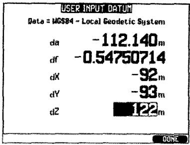
The five input parameters are as follows:
da Delta a
This is the difference in the semi-major axis from WGS-84 to the local datum, in meters.
df Delta f{x10,000}
This is the difference in flattening from the WGS-84 model to the local datum. Flattening is (a - b) / a , where a is the semi-major axis, and b is the semi-minor axis.
dX Delta X
These (dX, dY, dZ) are the differences in height from the center of the Earth from the WGS-84 model of the Earth's surface to the local datum's model of the Earth's surface in meters.
dY Delta Y
dZ Delta Z
EXAMPLE: For the MINNA / NIGERIA datum, the five parameters are as follows:
Delta a -112.14 meters
Delta f -0.54750714 (nondimensional)
Delta X -92. meters
Delta Y -93. meters
Delta Z 122. meters
To use the user defined datum just described, the datum selection USER DEF must be manually selected.
SPECIFICATIONS
SYSTEM DESCRIPTION
The GP-360ML is a fully automatic GPS receiver and navigator, providing exceptional accuracy and reliability for all navigation requirements. The standard model includes the following items:
GP-360ML GPS Navigator
Remote GPS antenna with 25 feet of cable
GP-360ML GPS Operator's Manual
Mounting Bracket with Knobs
Power / Data Cable
Warranty Card
SPECIFICATIONS
Maximum speed:
Maximum acceleration:
12 channel parallel receiver:
Position fix:
Time to first fix: Hot start:
Cold start:
First time global search:
Position update frequency:
5000 knots
6g
up to 12 satellites tracked
by Kalman filter, all satellites used
20 seconds typical
60 seconds typical
2.5 minutes typical
approximately 1 / second
Typical error
SA ON
SA OFF
Differential data, SA ON
Differential data, SA OFF
Position
50 meters
10 meters
5 meters
5 meters
Speed
0.80 knots
0.10 knots
0.50 knots
0.05 knots
PHYSICAL
Construction: JIS-4 water resistant, splashing water from any direction shall have no harmful effect (Splash resistant) Employs NMEA Version 2.0.
Width: 9.8^ , 249 mm
Height: 5.9^ , 150 mm
Depth: 3.1", 78.7 mm
Weight: 4.10 lbs, 32.8 oz, 930 g
Operating temperature: +14^ to +149^ F; -10^ to +65^ C
Input power: 10 - 32VDC , 0.9 amps
INSTALLATION AND ELECTRICAL WIRING
1. INSTALL THE RECEIVER UNIT
Although your GP-360ML is water resistant, it should be reasonably protected. Choose a receiver site free of moisture, weather, heat, shock, and vibration. The GPS should be at least 0.5 meter (20 inches) away from a magnetic compass. The receiver can be mounted on a bulkhead, overhead ceiling, or table top. Secure the tilt stand with screws or bolts.
2. HOOK UP THE POWER CABLE
A. Connect the RED wire of the power cable to +10 - 32VDC through a circuit breaker or fuse block with a current rating of 2 amperes. Connect the BLACK wire to the power ground.
B. Connect the power cable to any devices using serial data input or output, according to the following diagram. The serial output ports can drive up to three standard receiving devices.
Output Port 1: Connect YELLOW to serial data input on the device receiving data from the GPS.
Connect BLACK to serial data ground on the device receiving data from the GPS.
Output Port 2: Connect BLUE to serial data input on the device receiving data from GPS.
Connect BLACK to serial data ground on the device receiving data from GPS.
Output Port 3: Connect GREY to serial data input on the device receiving data from the GPS.
Connect BLACK to serial data ground on the device receiving data from the GPS.
Input Port 1: Connect GREEN to serial data output on the device sending data to the GPS.
Connect BLACK to serial data ground on the device sending data to the GPS.
Connect WHITE to the device receiving the timing pulse from the GPS.
Connect BLACK to the ground for the device receiving the timing pulse from the GPS.
Input Port 2: Connect WHITE to serial data output on the device sending data to the GPS.
Connect BLACK to serila data ground on the device sending data to the GPS.
CAUTION: All unused wires should be taped to prevent their contact with each other, or power, or ground.
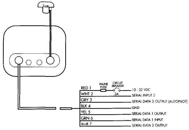
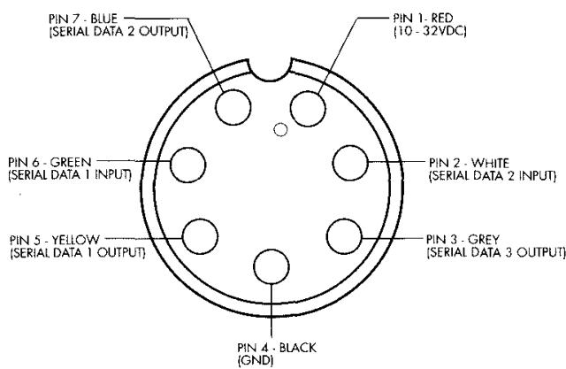
3. INSTALL THE ANTENNA
Mount the antenna vertically so it has as clear a view of the sky as possible. It should be AS LOW AS POSSIBLE while still getting a clear view of the sky, down to the horizon. If it is mounted high on the boat, the course and speed readings will respond to the antenna motion caused by pitching and rolling of the boat. If there is any question, do a temporary installation with duct tape. If performance is satisfactory, you can then install the antenna permanently. If there are problems, try another antenna location for better reception.
SUGGESTED ANTENNA LOCATIONS:
a) Two feet above the rail, at the bow or as far astern as possible.
b) Pilot house roof
c) Inside the pilot house close to the roof, if the roof is fiberglass and the antenna has a good view of the horizon from there, with no large metal structures above it.
The antenna can be mounted on a standard mast with 1" - 14 thread.
GP-360ML GPS ANTENNA
When it is necessary to cut the antenna cable to thread through a small hole, cut the connector end.

NOTE: Do not paint the GPS antenna.
Paint will reduce the GPS signals.
Connect the antenna cable to the BNC connector on the back of the GP-360ML. Mount the unit to the bracket and tighten the knobs.
Connect the power plug to the back of the GP-360ML. Turn on the unit by pressing the [PWR^] key for one second. To turn power off, hold the [PWR^] key down for three seconds until the display goes off.
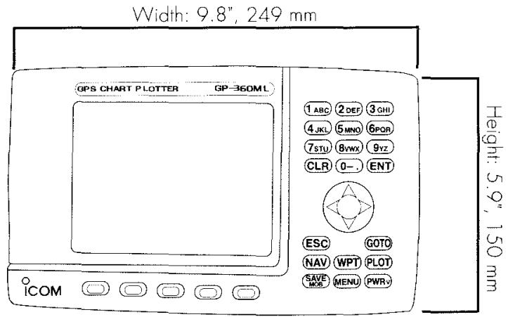
DIMENSIONS
Front of the GP-360ML
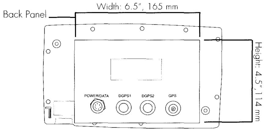
Back of the GP-360ML
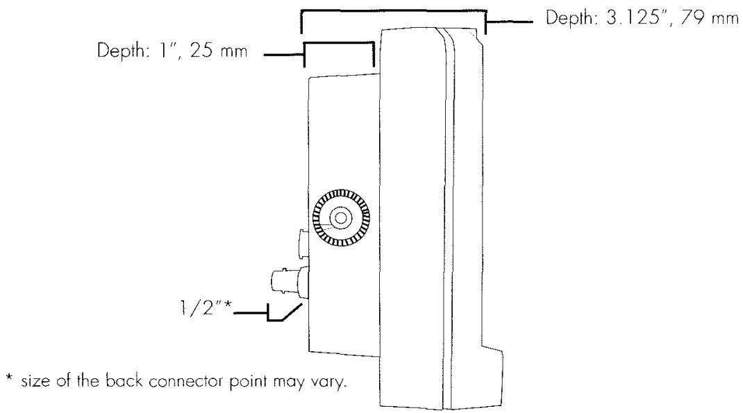
Side view of the GP-360ML
AUTOPILOT INTERFACE
To interface to an autopilot, follow these three points:
- Connect the GREY wire in the power / data cable to the autopilot signal input; and the BLACK wire to the autopilot signal ground.
- Turn the SERIAL I/O SETUP item SERIAL 3 from OFF to NMEA 0180. (NMEA 0183 on some autopilots.)
The BAUD rate is set at 4800, and the signal levels are "INVERSE TTL". If the autopilot gives a "NO DATA" or "BAD DATA" alarm, after the GPS has reached operating mode, check to make sure that steps 1-3 were done correctly.
AUTOPILOT OPERATION
- Turn the GP-360ML ON and wait for lat/lon page to appear.
- Turn the SERIAL I/O SETUP item SERIAL 3 from OFF to NMEA 0180. (NMEA 0183 on some autopilots.)
- Read the bearing to your destination from the display, and steer your vessel to until steady on that bearing.
- While looking at the "highway" display (under the NAV key), steer the vessel toward the center line until the indicated crosstrack error is at or near 0.00, and the ship's compass indicates the desired bearing.
- Follow the autopilot manufacturer's instructions for engaging the GPS to autopilot interface.
- Upon arrival at the destination, or when changing destination in mid-course, be sure to disengage the autopilot and repeat steps 2 through 5 to set your new course to a destination.
NOTE: Under the NMEA standards, 0.31 nautical miles is the largest crosstrack error that can be output through an autopilot interface. Although the GP-360ML will display up to 9.99 nm of cross track error, 0.31 nm is the largest error it can transmit to the autopilot.
MAINTENANCE
The memory of waypoints and Setup itmes is maintained by an internal lithium battery with a life that exceeds 5 years. When this battery becomes exhausted, the GPS will lose memory of waypoints and present position.
ICOM recommends that the GP-360ML be returned to ICOM Customer Service after 5 years, for the installation of a new battery. The program and software can be upgraded at the same time.
Call Customer Service (425) 454-8155, Tech Support (425) 454-7619 or E-mail: marine@icomamerica.com for instructions on how to return the unit for service.
*The memory battery is the only item requiring maintenance.
SERIAL DATA INPUT AND OUTPUT
Serial data input and output are controlled from the I/O SETUP screen.
Press MENU to bring up the main menu. Press the or keys to highlight SETUPS, and press [ENT]. The SETUPS submenu will be shown. Use the and keys to highlight SERIAL I/O. Press [ENT], to bring up the I/O SETUP screen.
| SERIAL I/O SETUP | |
| Serial 1: | OFF |
| Baud Rate: | 4800 |
| Serial 2: | OFF |
| Baud Rate: | 9600 |
| Serial 3: | OFF |
| Baud Rate: | 4800 |
| View Input Port: | 1 |
This screen will display choices to control the serial data formats and baud rates for three ports. Ports 1 & 2 have input and output lines, while port 3 has only an output line.
SERIAL 1: Default = off
BAUD RATE: Default = 4800
SERIAL 2: Default = off
BAUD RATE: Default = 4800
SERIAL 3: Default = off
BAUD RATE: Default = 4800
The choices for the data formats and baud rates are as follows:
NMEA-0183 This is the standard data format for interface to electronic charting systems, radars, and most other marine equipment.
NMEA-RMc This is the short form - high repetition rate data output, which is preferred for some electronic charting systems.
NMEA-RMa This is similar to RMc, but with a LORAN label. Some older instruments won't work unless they see a LORAN label, so they will work with this.
NAVLINK This is the NMEA0183 output, with a LORAN instead of a GPS label, provided for compatibility with older instruments that require a LORAN label.
NMEA-0180 This is the standard autopilot output. 180 + CDX This is the standard autopilot output, with additional range data that can be displayed on a Datamarine CDX.
NMEA-USER This format consists of ten NMEA sentences that are repeated about every five seconds. The sentences can be user selected, to provide compatibility with almost all equipment that use NMEA serial data input.
D-GPS This sets up the serial data input format for the SC-104 differential data input, and the output format to NMEA-USER. This is compatible with standard 285 - 325 kHz radiobeacon differential GPS data receivers.
When the format is selected, the baud rate will be set to the standard rate for the format selected. If you want a different rate, move the highlight to the baud rate field, and select one of the following rates: 150, 300, 600, 1200, 2400, 4800, 9600, and 19K2 (19,200).
When the NMEA-USER format is selected, ten different data sentences are sent in sequence, and repeated periodically about every two seconds. A display screen will appear that shows the default selection for the ten sentences, and allows you to select a different ten if desired. The default selection will work with about 90 per cent of equipment that uses serial data from a GPS or Loran.
If it is necessary that data be repeated more often than once per 3 seconds, selections can be repeated. For example, BWC and GGA are repeated in the default selection. If you wish to change the default selection, the following sentences are available.
APA APB BWC BWW GGA GLC GLL GL1 GLP GTD MLC RMA
RMB RMC SBK SCY SGD SLX SNU SNV VTG WCV XTE ZDA
ZTG ZZU — —
The NMEA user selectable data output allows the GPS to be configured to interface with almost all equipment that uses serial data input. If you are having difficulty getting the receiving equipment to work properly, call your dealer or ICOM Customer Service.
SERIAL DATA INPUT 1&2 TEST
The serial data input ports are on the following wires of the power cable:
Serial data input port 1:
GREEN Wire
Serial input port 1 return (ground):
BLACK Wire
Serial data input port 2:
BLUE Wire
Serial input port 2 return (ground):
BLACK Wire
The input data baud rate is 4800, and the data format is 8 bit no parity. The format is for NMEA 0183, and is not adjustable.
The serial input buffer 1 will now be shown.
To display the input data buffer 1 :
- Display the I/O SETUP screen.
- Highlight VIEW INPUT PORT: 1, and press [ENT].
To display the input buffer 2, highlight VIEW INPUT PORT: 2, and press [ENT].
INDEX
Alert Setup 46
Alarm Clock 47
Anchor Watch 47
Avoid 48
Border 47
Crosstrack Error (XTRACK) 47
Down Timer 48
Watch Timer 48
Waypoint Arrival 46
Almanac 52
Antenna Installation 72,76
Autopilot Interface 78, 81
Bearing 3,9,11,36,46,50,52,53,78
Beeper 43
Caution Screen 16
Charts 20-23
Chart Display Setups 21-22
Displaying a Position on a Chart 20
Inserting and Removing Caridges 20
Coordinate Systems 30,56
Courseine 52
Crosstrack Error 35,50,52,78
Course Error 52
Display Screens 17-18
Ephemeris 52
ESC, Escape 5
Estimated Time Enroute (Time-To-Go) 53
Glossary 52-54
GPS Overview 3
Heading 3,53
Installation 74
Leg 53
Light Intensity Adjustment 6
LORAN 53
LORAN Transmitter List 62-63
Magnetic North 53
Magnetic Variation 53
Maintenance 79
Man Overboard 28
Map 7,20,46,57,60,64
Map Datum Input 70
Map Datum List 64
Memory Battery 79
MGRS Coordinates 53
Name Entry 25
NAV FILTER 45-46
Navigation Setup 44-46
Navigation Screens 17
Number Entry 42
Parallel Route Offset 50
Position Display 6-7
Paths 32-35
Following a Path 35
Storing and Displaying a Path 34-35
Plot 4
Power Cable Wire List 74
PWR (Power on/off) 4
Routes 36-39
Creating a Route 37
Following a Route 38
Inverting a Route 38
Editing and Deleting a Route 39
Satellite Status 6
Saving Position 27
Screen Contrast 42
Selective Availability 54
Serial Data 49,80-83
Input Test 80, 82
Sentences (NMEA 0183) 81
Signal Quality Display 6
Specifications 72-73
Drawing of Dimensions 77
Specified Track Angle 50
Speed and Course Displays 6
Steering Displays 28
Time 8
Time Difference Coordinates TD 53
Time-To-Go (Estimated Time Enroute) 53
Track Log Setup 49
Units RNG/SPD, ALT/ACC 45
UTM Coordinates 54
Waypoints
Creating with Lat/Lon 17
Creating with LORAN TDs 30,60
Creating with MGRS Coordinates 56
Creating with UTM Coordinates 57
Date and Time of Creation 25
Deleting 28
Entering names 10
Entering Present Position 9-1
[GOTO] 4,27
List of Nearest Waypoints 26
Returning Home 15

www.icomamerica.com
MADE IN U.S.A
©2002 ICOM America, Inc. GPS-4804 10/02
- GP-360ML
- WELCOME TO ICOM AMERICA'S FAMILY OF PRODUCTS
- GPS signals most frequently receive close to 1000 msclosures under 35 and inside buildings . When the view of the sky is obscured ,
- Each of the following warning notices indicates that neglecting the suggested procedure or practices may result in death or serious personal injury.
- CAUTION
- Each of the following caution notices indicates that neglecting the suggested procedure or practices may result in personal injury or property damage.
- OTHER PRECAUTIONS
- NOTE:
- TABLE OF CONTENTS
- GETTING STARTED
- BASIC OPERATION
- CHARTS
- WAYPOINTS
- TRACK PLOTTING
- ROUTES
- SUNRISE, SUNSET, AND TIDES
- CUSTOMIZING SETUP CHOICES
- APPENDIX
- NAVIGATION
- GPS
- USING THE KEYPAD
- TURNING POWER ON AND OFF
- ADJUSTING THE BACKLIGHT
- DISPLAYING POSITION
- QUALITY POSITION FIX RELIABILITY
- THE WORLD MAP
- DISPLAYING A CHART
- SETTING TIME
- ENTERING A WAYPOINT
- ENTERING A WAYPOINT GRAPHICALLY
- SAVING YOUR STARTING POSITION
- STEERING TO A WAYPOINT
- RETURNING HOME
- BASIC OPERATION
- SUMMARY OF BASIC OPERATION
- BASIC OPERATION AND DISPLAY SCREENS
- 2.2
- CUSTOMIZING THE GP-360ML
- CHARTS
- ELECTRONIC CHART CARTRIDGES
- INSERTING AND REMOVING CARTRIDGES
- DISPLAYING A POSITION ON A CHART
- ZOOM LEVELS
- AUTO ZOOM FUNCTION
- NAVAGATIONAL AIDS, LIGHTS AND BUOYS
- CHART DISPLAY SETUPS
- WAYPOINTS
- WAYPOINTS
- CREATING A NEW WAYPOINT
- DATE AND TIME OF WAYPOINT CREATION
- FINDING A WAYPOINT
- THE LIST OF NEAREST WAYPOINTS
- GOING TO A WAYPOINT
- To go to a waypoint:
- THE SAVE KEY
- MAN OVERBOARD
- DELETING A WAYPOINT
- DELETING ALL WAYPOINTS
- RANGE AND BEARING FROM ONE WAYPOINT TO ANOTHER
- OTHER METHODS OF CREATING WAYPOINTS
- TRACK PLOTTING
- AUTOMATIC POSITION RECORDING
- PLOT OF PREVIOUS TRACK
- USING THE PREVIOUS TRACK TO RETURN HOME
- STORING AND DISPLAYING PATHS
- FOLLOWING A PATH
- RUTES
- COURSELINEs, LEGS, AND ROUTES
- PRESENT COURSELINE
- ROUTE NAVIGATION
- CREATING A ROUTE
- FOLLOWING A ROUTE
- EDITING AND DELETING ROUTES
- SUNRISE, SUNSET AND TIDES
- SUNRISE AND SUNSET
- 24 HOUR TIDE PREDICTION
- CUSTOMIZING SETUP CHOICES
- OPERATION SETUP
- NAVIGATION SETUP
- ALERT SETUP
- TRACK LOG SETUP
- SERIALI/OSETUP
- STEERING SETUP
- GLOSSARY
- MGRS AND UTM COORDINATES
- Creating a Waypoint in MGRS Coordinates
- Creating a Waypoint in UTM Coordinates
- LORAN C COORDINATES
- Creating a Waypoint in LORAN Coordinates
- NOTE
- LORAN TRANSMITTER LIST
- 4990
- 7960
- 8990
- 5930
- 7970
- 9610
- 5970
- 7980
- 9940
- 5990
- 7990
- 9960
- 9970
- 6780
- 8000
- 9980
- 7170
- 8290
- 9990
- 7930
- 8970
- 7950
- MAP DATUMS
- USER DEFINED DATUM
- SPECIFICATIONS
- SYSTEM DESCRIPTION
- PHYSICAL
- INSTALLATION AND ELECTRICAL WIRING
- INSTALL THE RECEIVER UNIT
- HOOK UP THE POWER CABLE
- INSTALL THE ANTENNA
- SUGGESTED ANTENNA LOCATIONS:
- GP-360ML GPS ANTENNA
- AUTOPILOT INTERFACE
- AUTOPILOT OPERATION
- MAINTENANCE
- SERIAL DATA INPUT AND OUTPUT
- SERIAL DATA INPUT 1&2 TEST
- INDEX
Marque : ICOM
Modèle : GP-360ML
Catégorie : Radio communication