SV12SD - Ponceuse HITACHI - Notice d'utilisation et mode d'emploi gratuit
Retrouvez gratuitement la notice de l'appareil SV12SD HITACHI au format PDF.

Questions des utilisateurs sur SV12SD HITACHI
0 question sur cet appareil. Repondez a celles que vous connaissez ou posez la votre.
Poser une nouvelle question sur cet appareil
Téléchargez la notice de votre Ponceuse au format PDF gratuitement ! Retrouvez votre notice SV12SD - HITACHI et reprennez votre appareil électronique en main. Sur cette page sont publiés tous les documents nécessaires à l'utilisation de votre appareil SV12SD de la marque HITACHI.
MODE D'EMPLOI SV12SD HITACHI
HITACHI
ORBITAL SANDER SCHWINGSCHLEIFER PONCEUSE ORBITALE LEVIGATRICE ORBITALE VLAKSCHUURMACHINE LIJADORA ORBITAL
SV 12V·SV 12SD·SV 12SE

natural_image
Line drawing of a mechanical power tool with a base plate and lever (no text or symbols)SV12V
Read through carefully and understand these instructions before use. Diese Anleitung vor Benutzung des Werkzeugs sorgfältig durchlesen und verstehen Lire soigneusement et bien assimiler ces instructions avant usage. Prima dell'uso leggere attentamente e comprendere queste istruzioni. Deze gebruiksaanwijzing s.v.p. voor gebruik zorgvuldig doorlezen. Leer cuidadosamente y comprender estas instrucciones antes del uso.

Handling instructions Bedienungsanleitung Mode d'emploi Istruzioni per l'uso Gebruiksaanwijzing Instrucciones de manejo
1

natural_image
Mechanical component diagram showing a rotating assembly with an arrow indicating rotational motion (no text or symbols)2
text_image
Technical diagram showing a hand holding a tool with numbered parts labeled 2 through 63
natural_image
Illustration of hands operating a mechanical device with a numbered label (4), no text or symbols present.4

text_image
Technical diagram showing mechanical assembly with numbered parts labeled 7 and 85

text_image
Diagram of a handheld device with numbered parts labeled ⑨ and ⑩, showing hand positioning and adjustment lines.6

natural_image
Line drawing of hands using a power tool on a workbench (no text or symbols)7
text_image
Diagram of a heat exchanger or cooling system with labeled component 118

natural_image
Technical line drawing of a power tool with labeled component (no text or symbols present)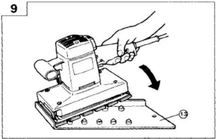
text_image
9 13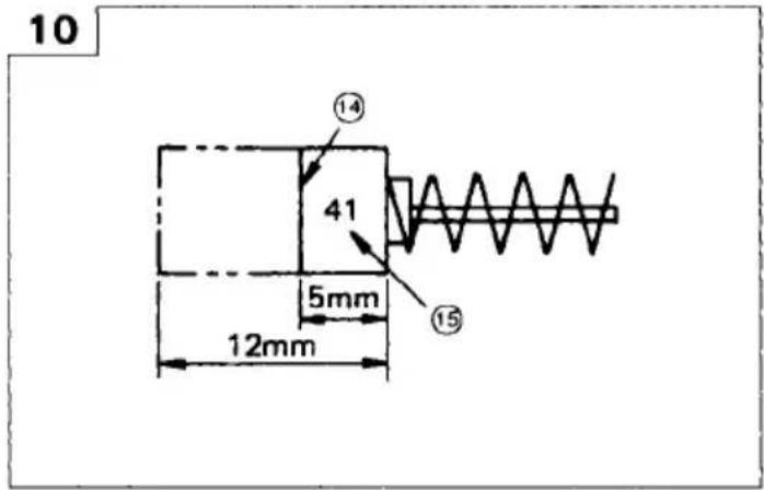
text_image
10 ⑭ 41 5mm 12mm ⑮
text_image
11 ⑯
text_image
12 21 18 17 19 20SV12V
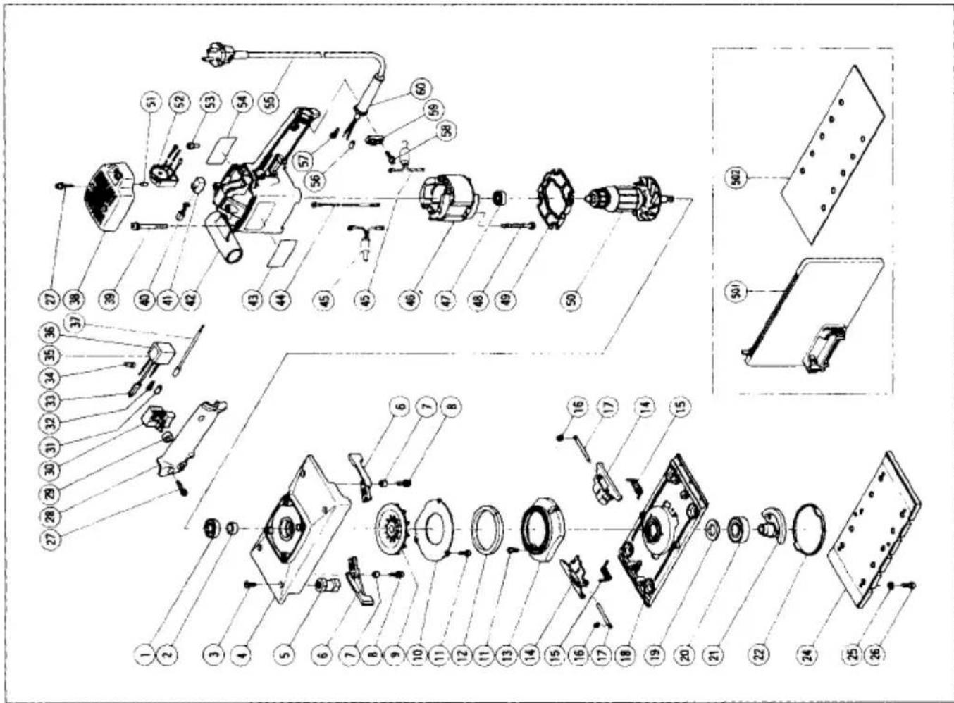
SV12V The exploded assembly drawing should be used only for authorized service facility.
| Item No. | Part Name |
| 46 | Stator |
| 47 | Ball Bearing (608VVC2) |
| 48 | Hexagon Hd. Tapping Screw D5 × 55 |
| 49 | Fan Guide |
| 50 | Armature |
| 51 | Bearing Lock |
| 52 | Speed Controller |
| 53 | Connector |
| 54 | Name Plate |
| 55 | Cord |
| 56 | Tube (D) |
| 57 | Terminal |
| 58 | Tapping Screw D4 × 16 |
| 59 | Cord Crip |
| 60 | Cord Armor |
| 501 | Dust Bag |
| 502 | Sanding Paper (Perforated) 114 × 280 AA80 |
Parts are subject to possible modification without notice due to improvements. The drawing and the list are parts structural drawing and parts list of model FSV12V. For other models refer to the drawing and the list.
| Item No. | Part Name |
| 1 | Ball Bearing (6001DDCM) |
| 2 | Sleeve |
| 3 | Flat Hd. Screw M5 × 14 |
| 4 | Frame |
| 5 | Rubber Leg |
| 6 | Lever |
| 7 | Distance Piece |
| 8 | Machine Screw M4 × 16 |
| 9 | Fan |
| 10 | Dust Fan Guide |
| 11 | Machine M4 × 10 |
| 12 | Felt (A) |
| 13 | Dust Guide |
| 14 | Paper Holder |
| 15 | Spring |
| 16 | E-Type Retaining Ring |
| 17 | Holder Bar |
| 18 | Bottom Plate |
| 19 | Felt |
| 20 | Ball Bearing (6203DDCM) |
| 21 | Balance Weight |
| 22 | Cover |
| 24 | Pad (Perforated) |
| 25 | Spring Lock Washer |
| 26 | Machine Screw M5 × 14 |
| 27 | Tapping Screw D4 × 20 |
| 28 | Handle Cover |
| 29 | Pushing Holder |
| 30 | Switch |
| 31 | Tube (D) |
| 32 | Terminal |
| 33 | Earth Terminal |
| 34 | Connector |
| 35 | Noise Suppressor |
| 36 | Support |
| 37 | Internal Wire |
| 38 | Top Cover |
| 39 | Machine Screw (+ - Hd.) M5 × 60 |
| 40 | Carbon Brush |
| 41 | Brush Holder |
| 42 | Housing |
| 43 | HITACHI Label |
| 44 | Internal Wire |
| 45 | Choke Coil |
text_image
Exploded view diagram of a mechanical assembly with numbered parts for identification| English | Deutsch | Français | |
| 1 | Clamping lever | Klemmhebel | Levier de verrouillage |
| 2 | Switch handle | Schaltergriff | Poignée de commutateur |
| 3 | Sanding paper | Schleifpapier | Papier de verre |
| 4 | Paper holder | Papierhalter | Support de papier |
| 5 | Bottom plate | Bodenplatte | Plaque inférieure |
| 6 | Pad | Polster | Tampon |
| 7 | Dust gate | Staubausgang | Volet à poussière |
| 8 | Dust bag holder | Staubbeutelhalter | Support de sac à poussière |
| 9 | Dust bag | Staubsack | Sac à poussière |
| 10 | Tab | Zapfen | Languette |
| 11 | Dial | Skala | Cadran |
| 12 | Cleaner adaptor | Reinigungsadapter | Adaptateur de nettoyeur |
| 13 | Punch plate | Stanzplatte | Plaque de poïçonnage |
| 14 | Wear limit | Verschleißgrenze | Limite d'usure |
| 15 | No. of carbon brush | Nr. der Kohlebürste | No. du balai de carbone |
| 16 | Top cover | Obere Abdeckung | Couvercle supérieur |
| 17 | Brush holder | Bürstenhalter | Porte-balai |
| 18 | Carbon brush | Kohlebürste | Balai de carbone |
| 19 | Brush terminal | Bürstenklemme | Extrémité de brosse |
| 20 | Bearing compartment | Lager Gehäuse | Logement du roulement |
| 21 | Internal wire | Innenverdrahtung | Câblage interne |
| Italiano | Nederland | Español | |
| 1 | Leva di blocco | Vergrendelingshendel | Palanca de inmovilización |
| 2 | Impugnatura interruttore | Schakelhendel | Asa del interruptor |
| 3 | Carta abrasive | Schuurpapier | Papel esmeril |
| 4 | Porta carta | Papierhouder | Portapapel |
| 5 | Piastra di fondo | Bodemmplaat | Placa inferior |
| 6 | Pannello | Stootkussen | Amortiguador |
| 7 | Uscita polvere | Stofschuif | Boca de salida del serrín |
| 8 | Sostegno porta polvere | Stofzakhouder | Soporte de la bolsa para el serrín |
| 9 | Sacca di raccolta della polvere | Stofzak | Bolsa colector de polvo |
| 10 | Linguetta | Nok | Proyección |
| 11 | Selettore | Schijf | Dial |
| 12 | Adattatore di pulizia | Reiningsadapter | Adaptador para aspiradora |
| 13 | Punzone | Doorslagplaat | Placa perforadora |
| 14 | Limite di usura | Slijtagegrens | Limite de uso |
| 15 | N. della spazzola di carbone | Nr.van de koolborstel | N. de carbón de contacto |
| 16 | Coperchio superiore | Bovendeksel | Cubierta superior |
| 17 | Portaspazzola | Borstelhouder | Portaescobillas de carbón |
| 18 | Spazzola di carbone | Koolborstel | Escobilla de carbón |
| 19 | Terminale spazzola | Borstelaansluitbus | Terminal de escobilla |
| 20 | Comparto del cuscinetto | Lagerhouder | Compartimiento del cojinete |
| 21 | Fili interni | Interne bedrading | Cableado interno |
| English | Deutsch | Français | |
| 1 | Clamping lever | Klemmhebel | Levier de verrouillage |
| 2 | Switch handle | Schaltergriff | Poignée de commutateur |
| 3 | Sanding paper | Schleifpapier | Papier de verre |
| 4 | Paper holder | Papierhalter | Support de papier |
| 5 | Bottom plate | Bodenplatte | Plaque inférieure |
| 6 | Pad | Polster | Tampon |
| 7 | Dust gate | Staubausgang | Volet à poussière |
| 8 | Dust bag holder | Staubbeutelhalter | Support de sac à poussière |
| 9 | Dust bag | Staubsack | Sac à poussière |
| 10 | Tab | Zapfen | Languette |
| 11 | Dial | Skala | Cadran |
| 12 | Cleaner adaptor | Reinigungsadapter | Adaptateur de nettoyeur |
| 13 | Punch plate | Stanzplatte | Plaque de poïçonnage |
| 14 | Wear limit | Verschleißgrenze | Limite d'usure |
| 15 | No. of carbon brush | Nr. der Kohlebürste | No. du balai de carbone |
| 16 | Top cover | Obere Abdeckung | Couvercle supérieur |
| 17 | Brush holder | Bürstenhalter | Porte-balai |
| 18 | Carbon brush | Kohlebürste | Balai de carbone |
| 19 | Brush terminal | Bürstenklemme | Extrémité de brosse |
| 20 | Bearing compartment | Lager Gehäuse | Logement du roulement |
| 21 | Internal wire | Innenverdrahtung | Câblage interne |
| Italiano | Nederland | Español | |
| 1 | Leva di blocco | Vergrendelingshendel | Palanca de inmovilización |
| 2 | Impugnatura interruttore | Schakelhendel | Asa del interruptor |
| 3 | Carta abrasive | Schuurpapier | Papel esmeril |
| 4 | Porta carta | Papierhouder | Portapapel |
| 5 | Piastra di fondo | Bodemmplaat | Placa inferior |
| 6 | Pannello | Stootkussen | Amortiguador |
| 7 | Uscita polvere | Stofschuif | Boca de salida del serrín |
| 8 | Sostegno porta polvere | Stofzakhouder | Soporte de la bolsa para el serrín |
| 9 | Sacca di raccolta della polvere | Stofzak | Bolsa colector de polvo |
| 10 | Linguetta | Nok | Proyección |
| 11 | Selettore | Schijf | Dial |
| 12 | Adattatore di pulizia | Reiningsadapter | Adaptador para aspiradora |
| 13 | Punzone | Doorslagplaat | Placa perforadora |
| 14 | Limite di usura | Slijtagegrens | Límite de uso |
| 15 | N. della spazzola di carbone | Nr.van de koolborstel | N'. de carbón de contacto |
| 16 | Coperchio superiore | Bovendeksel | Cubierta superior |
| 17 | Portaspazzola | Borstelhouder | Portaescobillas de carbón |
| 18 | Spazzola di carbone | Koolborstel | Escobilla de carbón |
| 19 | Terminale spazzola | Borstelaansluitbus | Terminal de escobilla |
| 20 | Comparto del cuscinetto | Lagerhouder | Compartimiento del cojinete |
| 21 | Fili interni | Interne bedrading | Cableado interno |
GENERAL OPERATIONAL PRECAUTIONS
- Keep work area clean. Cluttered areas and benches invite injuries.
- Consider work area environment. Don't expose power tools to rain. Don't use power tools in damp or wet locations. Keep work area well lit. Don't use tool in presence of flammable liquids or gases.
Power tools produce sparks during operation. They also spark when switching ON/OFF. Never use power tools in dangerous sites containing lacquer, paint, benzine, thinner, gasoline, gases, adhesive agents, and other materials which are combustible or explosive.
- Guard against electric shock. Prevent body contact with grounded surfaces. For example; pipes, radiators, ranges, refrigerator enclosures.
- Keep children away. Do not let visitors contact tool or extension cord. All visitors should be kept away from work area.
- Store idle tools. When not in use, tools should be stored in dry and high or locked-up place-out of reach of children.
- Don't force tool. It will do the job better and safer at the rate for which it was intended.
- Use right tool. Don't force small tool or attachment to do the job of a heavy-duty tool. Don't use tool for purpose not intended -for example -don't use circular saw for cutting tree limbs or logs.
- Dress properly. Do not wear loose clothing or jewelry. They can be caught in moving parts. Rubber gloves and non-skid footwear are recommended when working outdoors. Wear protective hair covering to contain long hair.
- Use eye protection. Also use face or dust mask if cutting operation is dusty.
- Don't abuse cord. Never carry tool by cord or yank it to disconnect from receptacle. Keep cord from heat, oil and sharp edges.
- Secure work. Use clamps or a vise to hold work. It's safer than using your hand and it frees both hands to operate tool.
- Don't overreach. Keep proper footing and balance at all times.
- Maintain tools with care. Keep tools sharp and clean for better and safer performance. Follow instructions for lubricating and changing accessories. Inspect tool cords periodically and if damaged, have repaired by authorized service facility. Inspect extension cords periodically and replace if damaged. Keep handles dry, clean, and free from oil and grease.
- Disconnect tools. When not in use, before servicing, and when changing accessories, such as blades,
bits, cutters.
- Remove adjusting keys and wrenches. Form habit of checking to see that keys and adjusting wrenches are removed from tool before turning it on.
- Avoid unintentional starting. Don't carry plugged-in tool with finger on switch. Be sure switch is off when plugging in.
- Outdoor use extension cords. When tool is used outdoors, use only extension cords intended for use outdoors and so marked.
- Stay alert. Watch what you are doing. Use common sense. Do not operate tool when you are tired.
- Check damaged parts. Before further use of the tool, a guard or other part that is damaged should be carefully checked to determine that it will operate properly and perform its intended function. Check for alignment of moving parts, binding of moving parts, breakage of parts, mounting, and any other conditions that may affect its operation. A guard or other part that is damaged should be properly repaired or replaced by an authorized service center unless otherwise indicated elsewhere in this instruction manual. Have defective switches replaced by authorized service center. Do not use tool if switch does not turn it on and off.
- Use the power tools only for applications specified in the Handling Instructions.
- To avoid personal injury, use only the accessories or attachment recommended in these handling instructions or in the HITACHI catalog.
- Let only the authorized service facility do the repairing. The manufacturer will not be responsible for any damages or injuries caused by repair by unauthorized persons or by mishandling of the tool.
- To ensure the designed operational integrity of power tools, do not remove installed covers or screws.
- Do not touch movable parts or accessories unless the power source has been disconnected.
- Use your tool at lower input than specified on the nameplate; otherwise, the finish may be spoiled and working efficiency reduced by motor overload.
- Do not wipe plastic parts with solvent. Solvents such as gasoline, thinner, benzine, carbon tetrachloride, alcohol, ammonia and oil containing chloric annex may damage and crack plastic parts. Do not wipe them with such solvent. Wipe plastic parts with a soft cloth lightly dampened with soapy water.
- Use only original HITACHI replacement parts.
- Disassemble this tool only for replacement of carbon brushes.
- Use the exploded assembly drawing on this handling instructions only for authorized servicing.
SPECIFICATIONS
| Model | SV12V | SV12SD | SV12SE |
| Voltage (by areas)* | (110V, 115V, 120V, 127V, 220V, 230V, 240V) ~ | ||
| Input* | 300W | ||
| No-Load Speed | 4000 - 10000/min. | 10000/min. | |
| Diam. of Orbit | 2.4 mm | ||
| Sanding Pad Size | 114 mm × 228 mm | ||
| Sanding Paper Size | 114 mm × 280 mm | ||
| Weight (w/o cord) | 2.8 kg | 2.8 kg | 2.6 kg |
* Be sure to check the nameplate on product as it is subject to change by areas.
STANDARD ACCESSORY
○ Sanding Paper 1
○ Dust Bag (for model SV12V, SV12SD).... 1
Standard accessories are subject to change without notice.
OPTIONAL ACCESSORIES (sold separately)
- Sanding paper
○ Perforated sanding paper for Model SV12V, SV12SD.
○ Non-perforated sanding paper for Model SV12SE.
Grain: AA40, AA60, AA80, AA100, AA120, AA150, AA180, AA220, AA240.
(1) Standard Type (Perforated or non-Perforated), 114 × 280 mm.
(2) Pressure Sensitive Type (Perforated or non-Perforated), 114 × 228 mm. - Magic Pad (Pressure Sensitive Type), 114 × 228 mm
(1) Perforated Pad (for Model SV12V, SV12SD)
(2) Non-Perforated Pad (for Model SV12SE) - Cleaner Adaptor (for Model SV12V, SV12SD).
- Punch Plate (for Model SV12V, SV12SD)
Optional accessories are subject to change without notice.
APPLICATIONS
○ Finish polishing of woodwork surfaces
○ Sanding surfaces of woodwork or sheet metal prior to painting, etc.
PRIOR TO OPERATION
- Power source
Ensure that the power source to be utilized conforms to the power requirements specified on the product nameplate.
- Power switch
Ensure that the power switch is in the OFF position. If the plug is connected to a power receptacle while the power switch is in the ON position, the power tool will start operating immediately, which could cause a serious accident.
- Extension cord
When the work area is removed from the power source, use an extension cord of sufficient thickness and rated capacity. The extension cord should be kept as short as practicable.
- Attaching sanding paper
(Start at Switch handle's side)
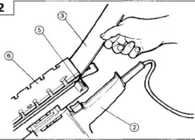
(1) Open Paper holder by turning the clamping lever (Fig.1).
(2) Place the sander as shown in Fig 2. Insert the sanding paper between the paper holder and the bottom plate until it can go no further.
(3) Match the width of the sanding paper with the width of the pad.
Return the clamping lever to its original position to secure the sanding paper.
(4)-1 When using perforated sanding paper.
To secure the other end of the sanding paper, pull the sanding paper while aligning the holes of the sanding paper with the holes of the pad.
(4)-2 When using non-perforated sanding paper.
Alig the sanding paper on the pad and pull the sanding paper to secure the other end.
CAUTION
(1) After mounting the sanding paper, return the clamping lever to its original position.
(2) The sanding paper must be precisely attached on the pad, ensuring that there is ample tension (leaving no slack). Loosely attached sanding paper could result in unevenly sanded surfaces and/or damage to the sanding paper itself.
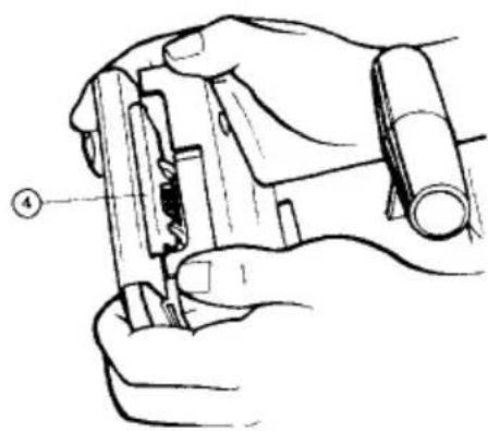
- Installing and removing the dust bag. (For models SV12V and SV12SD)
(1) Installation
As shown in Fig.4., hold the dust gate and push in the dust bag into the frame, s dust bag holder.
(2) Removal
As shown in Fig.5, push the dust gate,s tab hard and revove the dust bag from the frame.
PRACTICAL OPERATING PROCEDURES
CAUTION
Never apply water or grinding fluid when sanding. This could result in electrical shock.
- Switching the sander ON and OFF
By pulling the trigger an pushing the stopper, the switch will remain ON even when the trigger is released, promoting continuous, efficient operation. By pulling the trigger again, the stopper is released and the switch is turned OFF.
CAUTION
Never turn the power switch ON when the sander is contacting the surface to be sanded. This is necessary to preclude damage to the workpiece. The same applies when switching the power OFF.
- How to hold the Orbital Sander:
While gripping the knob with one hand and the handle with the other, lightly press the sander against the surface to be sanded so that the sanding paper uniformly contacts the surface, as shown in Fig.6. DO NOT apply excessive pressure to the sander while sanding. Excessive pressure may cause overload of the motor, reduce service life of the sanding paper, and lower sanding or polishing efficiency.
- How to move the Orbital Sander
For optimum operating efficiency, alternately move the sander forward and backward at a constant speed and balance.
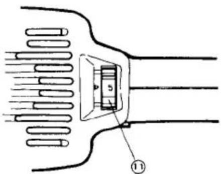
- Changing the rotating Speed (Model SV12V only) SV12V has an electronic control system which can be used to set the rotating speed between 4000 and 10,000 revolutions per minute.
As shown in Fig.7, dial position "1" is for minimum speed and position "5" for maximum speed.
MOUNTING THE OPTIONAL ACCESSORIES
- Mounting the magic pad.
Loosen the six screws.
Remove the pad and attach the magic pad.
CAUTION
Replace the pad only. Use the other parts without removing them.
2. Mounting the cleaner adapter (for Models SV12V and SV12SD) (Fig 8).
After mounting the dust collector hose onto the cleaner adapter, mouth the cleaner adapter onto the unit in the same way as mounting the dust bag.
MAINTENANCE AND INSPECTION
1. Emptying and cleaning the Dust Bag
(For models SV12V and SV12SD)
If the dust bag contains too much saw dust, dust collection will be affected. Empty the dust bag when it gets full.
Remove the dust bag, open the fastener, and dispose of the contents.
2. Inspecting the sanding paper
Since use of worn-out sanding paper will degrade efficiency and cause possible damage to the pad, replace the sanding paper as soon as excessive abrasion is noted.
3. Inspecting the mounting screws:
Regularly inspect all mounting screws and ensure that they are properly tightened. Should any of the screws be loose, retighten them immediately. Failure to do so could result in serious hazard.
4. Inspecting the carbon brushes (Fig. 10)
The motor employs carbon brushes which are consumable parts. Since an excessively worn carbon brush can result in motor trouble, replace the carbon brush with a new one having the same carbon brush No. shown in the figure when it becomes worn to or near the "wear limit". In addition, always keep carbon brushes clean and ensure that they slide freely within the brush holders.
5. Replacing carbon brushes:
○ Disassembling
(1) Loosen the two screws on the top cover, and remove the top cover. (Fig.11)
(2) Lift out the brush holder together with the carbon brush, while being very careful not to forcibly pull the internal wires within the brush holder.
(3) Remove the carbon brush from the brush holder.
○ Reassembling
(1) Insert the brush terminal into the brush holder. Turn the brush terminal 90°.
(2) While maintaining this brush terminal position as explained in (1), insert the new carbon brush into the brush holder.
(3) While pressing the carbon brush against the outside wall of the housing's bearing compartment, insert the brush holder into the housing's original position.
(4) Place the internal wire in the specified position.
Be very careful not to allow the internal wire to contact the armature or rotating parts of the motor. (Fig.12)
(5) Replace the top cover, while being careful to ensure it does not pinch the internal wire, and secure it firmly with the two screws.
CAUTION
Should the internal wire be pinched by the top cover or come in contact with the armature or rotating parts
of the motor, a serious danger of electric shock to the operator will be created. Exercise extreme caution in disassembling and reassembling the motor, following the above procedure exactly.
DO NOT attempt disassemble any parts other than those necessary to effect replacement of the carbon brush.
6. Maintenance of the motor
The motor unit winding is the very "heart" of the power tool. Exercise due care to ensure the winding does not become damaged and/or wet with oil or water.
NOTE
Due to HITACHI's continuing program of research and development, the specifications herein are subject to change without prior notice.
This appliance is produced to conform to the requirements of B.S. 800: 1977.
*This requirement is applicable to appliances for THE UNITED KINGDOM.
IMPORTANT
Correct connection of the plug
The wires of the main lead are coloured in accordance with the following code:
Blue: - Neutral
Brown: - Live
As the colours of the wires in the main lead of this tool may not correspond with the coloured markings identifying the terminals in your plug proceed as follows:
The wire coloured blue must be connected to the terminal marked with the letter N or coloured black.
The wire coloured brown must be connected to the terminal marked with the letter L or coloured red.
Neither core must be connected to the earth terminal.
NOTE
This requirement is provided according to BRITISH STANDARD 2769: 1984.
Therefore, the letter code and colour code may not be applicable to other markets except The United Kingdom.
The noise emitted by this power tool is measured in accordance with IEC 59 (CO) 11, IEC 704, DIN 45 635 Part 21, NFS 31-031 (84/537/EEC for concrete breakers).
The sound pressure level at the workplace can exceed 85 dB (A); in this case noise protection for the operator is required.