
GM-3000T - Amplificateur automobile PIONEER - Notice d'utilisation et mode d'emploi gratuit
Retrouvez gratuitement la notice de l'appareil GM-3000T PIONEER au format PDF.

| Type de produit | Amplificateur automobile 2 canaux |
| Marque | Pioneer |
| Modèle | GM-3000T |
| Alimentation | 14,4 V CC (10,8 – 15,1 V admissible) |
| Consommation de courant | 11,3 A (puissance continue, 4 Ω) |
| Fusible | 20 A (remplaçable) |
| Impédance de charge (stéréo) | 4 Ω (2 – 8 Ω admissible) |
| Impédance de charge (ponté) | 4 – 8 Ω |
| Puissance de sortie maximale | 80 W × 2 (stéréo) / 200 W × 1 (mono) |
| Puissance de sortie continue (stéréo) | 40 W × 2 (14,4 V, 4 Ω, 20-20 000 Hz, 0,08 % DHT) |
| Puissance de sortie continue (mono) | 100 W × 1 (14,4 V, 4 Ω, 20-20 000 Hz, 0,8 % DHT) |
| Réponse en fréquence | 10 – 45 000 Hz (+0 dB, -1 dB) |
| Rapport signal/bruit | 100 dB (IEC-A) |
| Distorsion harmonique totale | 0,008 % (10 W, 1 kHz) |
| Séparation des canaux | 55 dB (1 kHz) |
| Filtre passe-bas (fréquence de coupure) | 80 Hz |
| Filtre passe-bas (pente) | -12 dB/octave |
| Niveau d'entrée maximal (RCA) | 6,5 V / 22 kΩ |
| Niveau d'entrée maximal (haut-parleur) | 26 V / 40 kΩ |
| Dimensions (L × H × P) | 300 × 61 × 157 mm |
| Poids | 2,6 kg (sans câbles) |
| Système de mise à la terre | Type négatif |
| Fonctions principales | Contrôle de gain, interrupteur BFC, sélecteur LPF, indicateur d'alimentation, mode pontable, entrées RCA et haut-parleur |
| Sécurité | Circuit de protection contre les anomalies, fusible de protection, mise en garde contre le pontage incorrect |
| Pièces détachées et réparabilité | Fusible remplaçable (20 A), câbles batterie et terre spéciaux (RD-223, vendus séparément) |
FOIRE AUX QUESTIONS - GM-3000T PIONEER
Questions des utilisateurs sur GM-3000T PIONEER
0 question sur cet appareil. Repondez a celles que vous connaissez ou posez la votre.
Poser une nouvelle question sur cet appareil
Téléchargez la notice de votre Amplificateur automobile au format PDF gratuitement ! Retrouvez votre notice GM-3000T - PIONEER et reprennez votre appareil électronique en main. Sur cette page sont publiés tous les documents nécessaires à l'utilisation de votre appareil GM-3000T de la marque PIONEER.
MODE D'EMPLOI GM-3000T PIONEER
BRIDGEABLE POWER AMPLIFIER
AMPLIFICADOR DE POTENCIA EN PUENTE
Owner's Manual
GM-3000T
Manual del Propietario
PIONEER CORPORATION
4-1, MEGURO 1-CHOME, MEGURO-KU, TOKYO 153-8654, JAPAN
PIONEER ELECTRONICS (USA) INC.
P.O. Box 1540, Long Beach, California 90801-1540, U.S.A.
TEL: (800) 421-1404
PIONEER EUROPE NV
Haven 1087, Keetberglaan 1, B-9120 Melsele, Belgium
TEL: (0) 3/570.05.11
PIONEER ELECTRONICS ASIACENTRE PTE. LTD.
253 Alexandra Road, #04-01, Singapore 159936
TEL: 65-6472-1111
PIONEER ELECTRONICS AUSTRALIA PTY. LTD.
178-184 Boundary Road, Braeside, Victoria 3195, Australia
TEL: (03) 9586-6300
PIONEER ELECTRONICS OF CANADA, INC.
300 Allstate Parkway, Markham, Ontario L3R OP2, Canada
TEL: (905) 479-4411
PIONEER ELECTRONICS DE MEXICO, S.A. de C.V.
Blvd.Manuel Avila Camacho 138 10 piso
Col.Lomas de Chapultepec, Mexico, D.F. 11000
TEL: 55-9178-4270
Published by Pioneer Corporation.
Copyright © 2004 by Pioneer Corporation.
All rights reserved.
Publicado por Pioneer Corporation.
Copyright © 2004 Pioneer Corporation.
Todos los derechos reservados.
Printed in China
Impreso na China
Before Using This Product
Thank you for purchasing this PIONEER product. Before attempting operation, be sure to read this manual.
In case of trouble
When the unit does not operate properly, contact your dealer or the nearest authorized PIONEER Service Station.
CAUTION
Never replace the fuse with one of greater value or rating than the original fuse. Use of an improper fuse could result in overheating and smoke and could cause damage to the product and injury including burns.
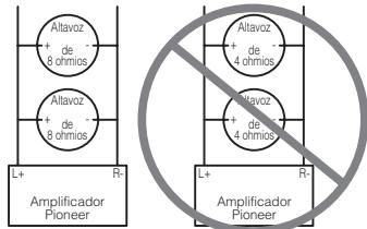
CAUTION
Diagram A - Proper
Diagram B - Improper
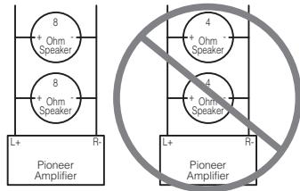
4 Ohm Bridged Mode
2 Ohm Bridged Mode
Do NOT install or use your Pioneer amplifier by wiring speakers rated at 4 Ohm (or lower) in parallel to achieve a 2 Ohm (or lower) bridged mode (Diagram B).
Amplifier damage, smoke, and overheating could result from improper bridging. The amplifier surface could also become hot to the touch and minor burns could result.
To properly install or use a bridged mode for a two-channel amplifier and achieve a 4 load, wire two 8 speakers in parallel with Left + and Right - (Diagram A) or use a single 4 speaker. For a four-channel
amplifier, follow the speaker output connection diagram for bridging as shown on the back of your amplifier, and wire two 8 speakers in parallel to achieve a 4 load or use a single 4 speaker per channel.
If you have any questions or concerns, please contact your local authorized Pioneer dealer or call Pioneer customer service.
WARNING
- Always use the special red battery and ground wire [RD-223], which is sold separately. Connect the battery wire directly to the car battery positive terminal (+) and the ground wire to the car body.
- Do not touch the amplifier with wet hands.
Otherwise you may get an electric shock. Also, do not touch the amplifier when it is wet.
- For traffic safety and to maintain safe driving conditions, keep the volume low enough so that you can still hear normal traffic sound.
- Check the connections of the power supply and speakers if the fuse of the separately sold battery wire or the amplifier fuse blows. Detect the cause and solve the problem, then replace the fuse with another one of the same size and rating.
- To prevent malfunction of the amplifier and speakers, the protective circuit will cut the power supply to the amplifier (sound will stop) when an abnormal condition occurs. In such a case, switch the power to the system OFF and check the connection of the power supply and speakers. Detect the cause and solve the problem.
- Contact the dealer if you cannot detect the cause.
- To prevent an electric shock or short-circuit during connection and installation, be sure to disconnect the negative (−) terminal of the battery beforehand.
- Confirm that no parts are behind the panel when drilling a hole for installation of the amplifier. Be sure to protect all cables and important equipment such as fuel lines, brake lines and the electrical wiring from damage.
Setting the Unit
Gain Control
If the sound level is too low, even when the volume of the car stereo used along with this power amplifier is turned up, turn gain control on the front of the power amplifier clockwise. If the sound distorts when the volume is turned up, turn the gain control counter-clockwise.
- When using with an RCA equipped car stereo (standard output of 500 mV), set to the NORMAL position. When using with an RCA equipped Pioneer car stereo with max. output of 4 V or more, adjust level to match the car stereo output level.
- If you hear too much noise when using the speaker input terminals, turn the gain control counter-clockwise.
LPF (Low-Pass Filter) Select Switch
Set the LPF select switch as follows according to the type of speaker that is connected to the speaker output connector and the car stereo system:
| LPF Select Switch | Audio frequency range to be output | Speaker Type | Remarks |
| LPF (left) | Very Low Frequency range | Subwoofer | Connect a subwoofer. |
| OFF (right) | Full range | Full range |

- Disconnect the negative (−) terminal of the battery to avoid the risk of short-circuit and damage to the unit.
- Secure the wiring with cable clamps or adhesive tape. To protect the wiring, wrap adhesive tape around it where they lie against metal parts.
-
Do not route wires where they will get hot, for example where the heater will blow over them. If the insulation heats up, it may become damaged, resulting in a short-circuit through the vehicle body.
-
Make sure that wires will not interfere with moving parts of the vehicle, such as the gearshift, handbrake or seat sliding mechanism.
- Do not shorten any wires. Otherwise the protection circuit may fail to work when it should.
- Never feed power to other equipment by cutting the insulation of the power supply wire to tap from the wire. The current capacity of the wire will be exceeded, causing overheating.
- Never replace the fuse with one of greater value or rating than the original fuse. Use of an improper fuse could result in overheating and smoke and could cause damage to the product and injury including burns.

To prevent damage and/or injury
- Do not ground the speaker wire directly or connect a negative (−) lead wire for several speakers.
- This unit is for vehicles with a 12-volt battery and negative grounding. Before installing it in a recreational vehicle, truck or bus, check the battery voltage.
- If the car stereo is kept on for a long time while the engine is at rest or idling, the battery may go dead. Turn the car stereo off when the engine is at rest or idling.
-
If the system remote control wire of the amplifier is connected to the power terminal through the ignition switch (12 V DC), the amplifier will always be on when the ignition is on— regardless of whether the car stereo is on or off. Because of this, the battery could go dead if the engine is at rest or idling.
-
Speakers to be connected to the amplifier should conform with the standards listed below. If they do not conform, they may catch fire, emit smoke or become damaged. The speaker impedance must be 2 to 8 ohms for stereo connection, and 4 to 8 ohms for monaural and other bridge connection.
- Install and route the separately sold battery wire as far away as possible from the speaker wires. Install and route the separately sold battery wire ground wire, speaker wires and the amplifier as far away as possible from the antenna, antenna cable and tuner.
- Cords for this product and those for other products may be different colors even if they have the same function. When connecting this product to another product, refer to the supplied Installation manuals of both products and connect cords that have the same function.
| Speaker Channel | Speaker Type | Power |
| Two-channel | Subwoofer | Nominal input: Min. 55 W |
| Other than subwoofer | Max. input: Min. 80 W | |
| One-channel | Subwoofer | Nominal input: Min. 125 W |
| Other than subwoofer | Max. input: Min. 200 W |
Connection Diagram
flowchart
graph TD
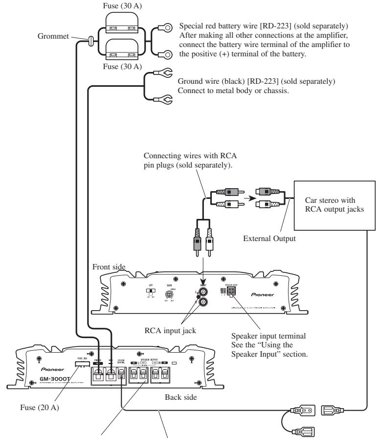
A["Fuse (30 A)"] --> B["Special red battery wire [RD-223"] (sold separately)]
A --> C["After making all other connections at the amplifier, connect the battery wire terminal of the amplifier to the positive (+) terminal of the battery."]
D["Fuse (30 A)"] --> E["Ground wire (black) [RD-223"] (sold separately)]
D --> F["Connect to metal body or chassis."]
G["Front side"] --> H["RCA input jack"]
H --> I["Speaker input terminal See the “Using the Speaker Input” section."]
J["Fuse (20 A)"] --> K["Back side"]
L["External Output"] --> M["Car stereo with RCA output jacks"]
Speaker output terminal See the “Connecting the Speaker wires” section for speaker connection instructions.
System remote control wire (sold separately)
Connect the male terminal of this wire to the system remote control terminal of the car stereo (SYSTEM REMOTE CONTROL). The female terminal can be connected to the auto-antenna relay control terminal. If the car stereo does not have a system remote control terminal, connect the male terminal to the power terminal through the ignition switch.
Connecting the Power Terminal
- Always use the special red battery and ground wire [RD-223], which is sold separately. Connect the battery wire directly to the car battery positive terminal (+) and the ground wire to the car body.
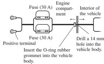
1. Pass the battery wire from the engine compartment to the interior of the vehicle.
- After making all other connections to the amplifier, connect the battery wire terminal of the amplifier to the positive (+) terminal of the battery.
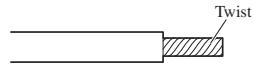
2. Twist the battery wire, ground wire and system remote control wire.
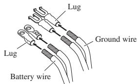
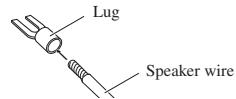
3. Attach lugs to wire ends. Lugs not supplied.
- Use pliers, etc., to crimp lugs to wires.
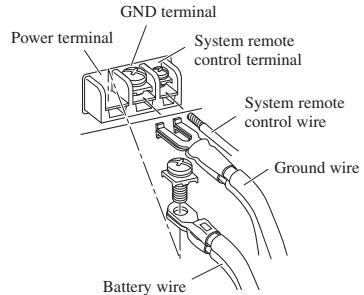
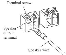
4. Connect the wires to the terminal.
- Fix the wires securely with the terminal screws.
Connecting the Speaker Output Terminals
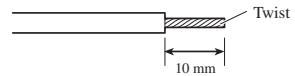
1. Expose the end of the speaker wires using nippers or a cutter by about 10 mm and twist.
2. Attach lugs to speaker wire ends. Lugs not supplied.
- Use pliers, etc., to crimp lugs to wires.
3. Connect the speaker wires to the speaker output terminals.
- Fix the speaker wires securely with the terminal screws.
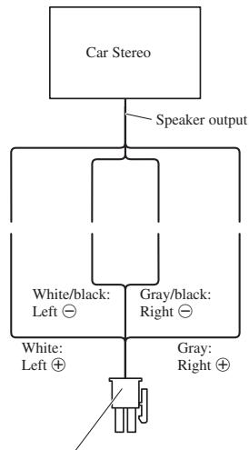
Using the Speaker Input
Connect the car stereo speaker output wires to the amplifier using the supplied speaker input connector.
- Do not connect both the RCA input and the speaker input at the same time.
■ Connections when using the speaker input
flowchart
graph TD
    A["Car Stereo"] --> B["Speaker output"]
    B --> C["White/black: Left ⊖"]
    B --> D["Gray/black: Right ⊖"]
    C --> E["White: Left ⊕"]
    D --> F["Gray: Right ⊕"]
Speaker input connector
To speaker input terminal of this unit.
Connecting the Unit
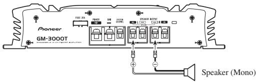
Connecting the Speaker wires
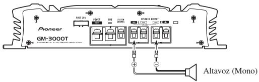
The speaker output mode can be two-channel (stereo) or one-channel (mono). Connect the speaker leads to suit the mode according to the figures shown below.
- Do not connect both the RCA input and the speaker input at the same time.
Two-channel mode (stereo)
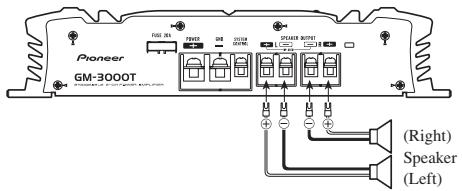
One-channel mode (mono)
Installation
CAUTION
- Do not install in:
—Places where it could injure the driver or passengers if the vehicle stops suddenly.
—Places where it may interfere with the driver, such as on the floor in front of the driver's seat. - Make sure that wires are not caught in the sliding mechanism of the seats, resulting in a short-circuit.
- Confirm that no parts are behind the panel when drilling a hole for installation of the amplifier. Protect all cables and important equipment such as fuel lines, brake lines and electrical wiring from damage.
- Install tapping screws in such a way that the screw tip does not touch any wire. This is important to prevent wires from being cut by vibration of the car, which can result in fire.
- To prevent electric shock, do not install the amplifier in places where it might come in contact with liquids.
- To ensure proper installation, use the supplied parts in the manner specified. If any parts other than the supplied ones are used, they may damage internal parts of the amplifier, or they may become loose causing the amplifier to shut down.
CAUTION:
To prevent malfunction and/or injury
- To ensure proper heat dissipation of the amplifier, be sure of the following during installation.
—Allow adequate space above the amplifier for proper ventilation.
—Do not cover the amplifier with a floor mat or carpet. - Do not install the amplifier near a door where it may get wet.
- Do not install the amplifier on unstable places such as the spare tire board.
- The best location for installation differs with the car model and installation location. Secure the amplifier at a sufficiently rigid location.
- Make temporary connections first and check that the amplifier and the system operate properly.
- After installing the amplifier, confirm that the spare tire, jack and tools can be easily removed.
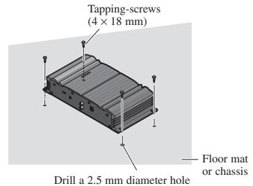
Example of installation on the floor mat or on the chassis
-
Place the amplifier where it is to be installed. Insert the supplied tapping screws (4 × 18 mm) into the screw holes. Push on the screws with a screwdriver so they make marks where the installation holes are to be located.
-
Drill 2.5 mm diameter holes at the point marked, and install the amplifier, either on the carpet or directly to the chassis.
Specifications
Power source 14.4 V DC (10.8 — 15.1 V allowable)
Grounding system ...... Negative type
Current consumption 11.3 A (at continuous power, 4 Ω)
Average current drawn* 3.8 A (4 Ω for two channels) 5.9 A (4 Ω for one channel)
Fuse 20 A
Dimensions 300 (W) × 61 (H) × 157 (D) mm
Weight 2.6 kg (Leads for wiring not included)
Maximum power output 80 W × 2 / 200 W × 1
Continuous power output 40 W × 2 (at 14.4 V, 4 Ω, 20 — 20,000 Hz, 0.08% THD)
100 W × 1 (at 14.4 V, 4 Ω, 20 — 20,000 Hz, 0.8% THD)
50 W × 2 (at 14.4 V, 2 Ω, 20 — 20,000 Hz, 0.8% THD)
Load impedance 4 Ω (2 — 8 Ω allowable)
(Bridge connection: 4 — 8 Ω allowable)
Frequency response 10 — 45,000 Hz (+0 dB, -1 dB)
Signal-to-noise ratio 100 dB (IEC-A network)
Distortion 0.008% (10 W, 1 kHz)
Separation 55 dB (1 kHz)
Low pass filter .... Cut off frequency: 80 Hz
Cut off slope: -12 dB/oct
Maximum input level/impedance .... RCA: 6.5 V/22 kΩ (0.4 — 6.5 V)
Speaker: 26 V/40 kΩ (1.6 — 26 V)
Note:
- Specifications and the design are subject to possible modification without notice due to improvements.
\*Average current drawn
- The average current drawn is nearly the maximum current drawn by this unit when an audio signal is input. Use this value when working out total current drawn by multiple power amplifiers.
Antes de usar este producto
Muchas gracias por la adquisición de este producto PIONEER. Antes de tratar de operarlo, lea atentamente este manual.
En caso de desperfectos
Si esta unidad no funciona correctamente, póngase en contacto con su distribuidor o con el Centro de Servicio PIONEER autorizado más cercano.
PRECAUCION
No reemplace nunca el fusible por uno con un valor de régimen mayor que el fusible original. El uso de un fusible inadecuado podría causar el sobrecalantamiento o humo, así como podría causar daños al producto y lesiones, incluyendo quemaduras.
PRECAUCION
Diagrama A - Correcto
Diagrama B - Incorrecto
Modo de conexión en
puente de 4 ohmios
Modo de conexión en
puente de 2 ohmios
NO instale o use el amplificador Pioneer mediante la conexión de los cables de las bocinas de 4 ohmios nominales (o menos) en paralelo para lograr un modo en puente de 2 ohmios (o menos) (Diagrama B). Realizar un puente incorrecto podría resultar en un sobrecalentamiento y daño del amplificador, así como en un desprendimiento de humo del mismo. La superficie del amplificador podría también ponerse caliente al tacto y resultar en quemaduras ligeras.
Para instalar o usar adecuadamente el modo de puente para un amplificador de dos canales y lograr una carga de 4 Ω,
conecte los cables de dos bocinas de 8 Ω en paralelo con Izquierdo + y Derecho - (Diagrama A), o use una sola bocina de 4 Ω. Para un amplificador de cuatro canales, siga el diagrama de la conexión de salida de la bocina para crear un puente como se muestra en la parte posterior del amplificador, y conecte los cables de dos bocinas de 8 Ω en paralelo para lograr una carga de 4 Ω o use una sola bocina de 4 Ω por canal. Si tiene preguntas o dudas, comuníquese con el distribuidor Pioneer autorizado en su localidad o llame al Servicio al Cliente de Pioneer.
ADVERTENCIA
- Siempre utilice el cable de batería rojo especial y el cable de tierra [RD-223], vendidos separadamente. Conecte el cable de batería directamente al terminal positivo de la batería del vehículo (+) y el cable de tierra a la carrocería del vehículo.
- No toque en el amplificador con las manos mojadas. Caso contrario, usted puede llevar un choque eléctrico. Igualmente, no toque en el amplificador cuando esté mojado.
- Para seguridad del tráfico y para mantener condiciones de conducción seguras, mantenga el volumen suficientemente bajo de manera que aun se pueda escuchar el sonido del tráfico normal.
- Verifique las conexiones del suministro de energía y altavoces para ver si el fusible del cable de batería vendido separadamente o el fusible del amplificador se queman. Detecte la causa y solu-cione el problema, y reemplace el fusible con un otro del mismo tamaño y régimen.
- Para evitar mal funcionamiento del amplificador y altavoces, el circuito de protección cortará la alimentación al amplificador (el sonido se detendrá) cuando se produzca una situación anormal. En tal caso, apague el sistema y verifique la conexión de la alimentación y altavoces. Detecte la causa y resuelva el problema.
- Contacte a su distribuidor si no puede detectar la causa.
- Para evitar choques eléctricos o cortocircuitors durante la conexión e instalación, asegúrese de desconectar el terminal negativo (–) de la batería antes de proceder.
- Confirme que ninguna parte quede detrás del panel, cuando perfore un orificio para la instalación del amplificador. Asegúrese de proteger todos los cables y equipos importantes, tales como líneas de combustibles, líneas de frenos y el cableado eléctrico.
Ajuste de esta unidad
Control de ganancia
Si el nivel del sonido está muy bajo, aún cuando se aumenta el volumen del equipo estéreo para automóvil usado con este amplificador de potencia, gire a la izquierda el control de ganancia en la parte delantera del amplificador de potencia. Si hay distorsión del sonido cuando se aumenta el volumen del equipo estéreo de automóvil, gire los controles a la izquierda.
- Cuando se usa un estéreo de automóvil equipado con RCA (salida estándar de 500 mV), ajuste a la posición NORMAL. Cuando use con un estéreo de automóvil Pioneer equipado con RCA con una salida máxima de 4 V o más, ajuste el nivel para adecuarse al nivel de salida del estéreo del automóvil.
- Si se oye ruido excesivo cuando se usan los terminales de entrada de altavoz, gire el control de nivel a la izquierda.
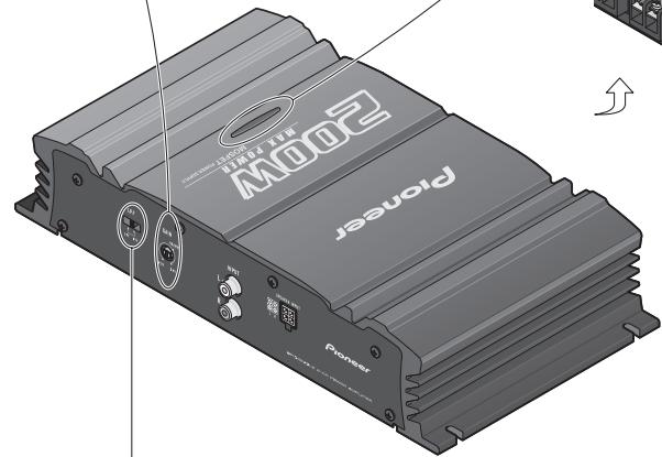
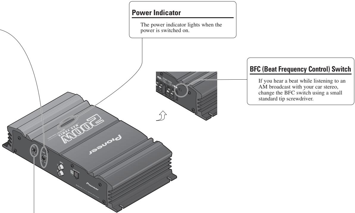
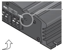
Indicador de alimentación
El indicador de alimentación se ilumina cuando la unidad se encuentra activada.
Interruptor BFC (Control de la frecuencia de batido)
Si escucha sonidos de batido mientras está recibiendo una emisora de AM con su estéreo de automóvil, cambie el interruptor BFC usando un destornillador pequeño.
Interruptor de selección LPF (Filtro de paso bajo)
Ajuste el interruptor de selección LPF de la manera siguiente, de acuerdo al tipo de altavoz que se encuentra conectado al conector de salida de altavoz y al sistema estéreo de automóvil:
| Interruptor de selección LPF | Gama de frecuencia de audio a ser generada | Tipo de altavoz | Observaciones |
| LPF (izquierda) | Gama de frecuencia muy baja | Altavoz de graves secundario | Conecte a un altavoz de graves secundario. |
| OFF (derecha) | Gama completa | Gama completa |

PRECAUCION
- Quite el terminal negativo (–) de la batería para evitar riesgo de cortocircuitos y daño a la unidad.
- Asegure el alambrado con abrazaderas de cable o cinta adhesiva. Para proteger el alambrado, envuelva cinta adhesiva alrededor de ellos en donde contacta con partes metálicas.
- No tienda cables por donde puedan calentarse, por ejemplo donde el calentador sople sobre ellos. Si la aislación se calienta, podría resultar dañada, resultando en cortocircuito a través de la carrocería del vehículo.
-
Asegúrese que los alambres no interfieran con partes móviles del vehículo como la palanca de cambios, el freno de mano o el mecanismo de deslizamiento de los asientos.
-
No corte ningún cable. De otra manera, el circuito de protección podría no funcionar cuando debiera.
- Nunca alimente otro equipo cortando la aislación del cable de alimentación y conectándolo al cable. La capacidad de corriente del cable será excedida, causando sobrecalentamiento.
- No reemplace nunca el fusible por uno con un valor de régimen mayor que el fusible original. El uso de un fusible inadecuado podría causar el sobrecalantamiento o humo, así como podría causar daños al producto y lesiones, incluyendo quemaduras.

PRECAUCION:
Para evitar daños y/o lesiones
- No conecte a tierra (masa) el cable del altavoz directamente ni conecte un cable negativo (−) a varios altavoces.
- Esta unidad es para vehículos con una batería de 12 voltios y terminal negativo a tierra. Antes de instalar en un vehículo de recreación, camión u ómnibus, verifique el voltaje de la batería.
- Si el sistema estereofónico del coche está funcionando por un largo período de tiempo mientras el motor permanece inactivo o en marcha al ralentí, la batería puede agotarse. Apague el estéreo de automóvil cuando el motor se encuentre funcionando en marcha al ralentí o permanece inactivo.
-
Si el cable del control remoto del sistema del amplificador se conecta al terminal de alimentación a través del interruptor de encendido (12 V de CC), el amplificador estará siempre activado cuando el encendido está activado, sin considerar de si el estéreo de automóvil se encuentra activado o desactivado. Debido a esto, la batería puede agotarse si deja el motor funcionando en marcha al ralentí o permanece inactivo.
-
Los altavoces a ser conectados al amplificador deben estar conforme con las normas listadas debajo. Si no cumplen con las normas, pueden combustionar, emitir humos o dañarse. La impedance del altavoz debe ser de 2 a 8 ohmios para conexiones estéreo, y de 4 a 8 ohmios para conexiones monaurales y acoplamientos en derivación.
- Instale y coloque el cable de batería vendido separadamente lo más alejado posible de los cables de los altavoces. Instale y coloque el cable de batería y cable de tierra vendidos separadamente, los cables de los altavoces, y el amplificador lo más alejados posible de la antena, cable de antena y sintonizador.
- Los cables para esta unidad y aquéllas para las unidades pueden ser de colores diferentes aun si tienen la misma función. Cuando se conecta esta unidad a otra, refiérase a los manuales de instalación de ambas unidades y conecte los cables que tienen la misma función.
| Canal de altavoces | Tipo de altavoz | Alimentación |
| Dos canales | Altavoz de graves secundario | Entrada nominal: 55 W mín. |
| Diferente a un altavoz de graves secundario | Entrada máxima: 80 W mín. | |
| Un canal | Altavoz de graves secundario | Entrada nominal: 125 W mín. |
| Diferente a un altavoz de graves secundario | Entrada máxima: 200 W mín. |
Diagrama de conexión
![Fusible (30 A) Ojal Cable de batería rojo especial [RD-223] (en venta por separado) Después de realizar todas las conexiones al amplificador, conecte el terminal del conductor de batería del amplifi- cador al terminal positivo (+) de la batería. Fusible (30 A) Cable de puesta a tierra (negro) [RD-223] (en venta por separado) Conecte a una carrocería metálica o chasis. Conexión de cables con los enchufes de conector RCA (en venta por separado). Salida externa Estéreo de automóvil con tomas con conector de salida RCA Lado delantero Pioneer Tomas de conector de entrada RCA Terminal de entrada de altavoz Vea la sección "Uso de la entrada de altavoz". Fusible (20 A) Lado trasero](/content/2025/01/119087/images/bbe3b6592104a012bea37a21e8361f7868e57a83d76f238ba37638504dde7600.jpg)
Terminal de salida de altavoz Vea la sección “Conexión de los cables de altavoces” para las instrucciones de conexión del altavoz.
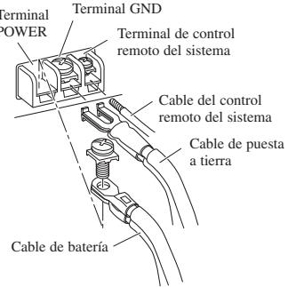
Cable del control remoto del sistema (en venta por separado) Conecte el terminal macho de este hilo al terminal de control remoto de sistema del equipo estéreo para automóvil (SYSTEM REMOTE CONTROL). El terminal hembra puede ser conectado al terminal de control del relé de antena. Si el estéreo de automóvil no tiene un terminal de control remoto del sistema, conecte el terminal macho al terminal de alimentación a través del interruptor de encendido.
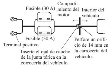
Conexión del terminal de alimentación
- Siempre utilice el cable de batería rojo especial y el cable de tierra [RD-223], vendidos separadamente. Conecte el cable de batería directamente al terminal positivo de la batería del vehículo (+) y el cable de tierra a la carrocería del vehículo.
1. Pase el cable de batería desde el compartimiento del motor al interior del vehículo.
- Luego de hacer todas las otras conexiones al amplificador, conecte el terminal del conductor de batería del amplificador al terminal positivo (+) de la bateria.
2. Tuerza el cable de batería, cable de puesta a tierra y cable de control remoto del sistema.

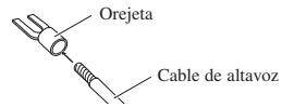
3. Fije las orejetas a los extremos de los cables. Orejetas no suministrados.
- Utilice alicates, etc. para plegar las orejetas a los cables.
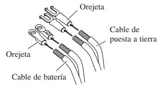
4. Conecte los cables al terminal.
- Fijar los cables firmemente utilizando los tornillos para terminales.
Terminal POWER
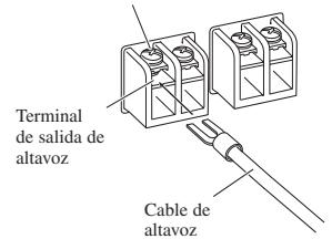
Conexión del terminal de salida de altavoz
- Desnude la extremidad de los cables de altavoces utilizando alicates o una tajadera por aproximadamente 10 mm y tuérzala.

2. Fije las orejetas a los extremos de los cables de altavoz. Orejetas no suministrados.
- Utilice alicates, etc. para plegar las orejetas a los cables.
3. Conecte los cables de altavoz al terminal de salida de altavoz.
- Fije los cables firmemente utilizando los tornillos para terminales.
Torrillo de terminal
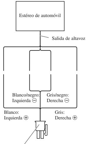
Uso de la entrada de altavoz
Conecte los hilos de la salida de altavoz del estéreo de automóvil al amplificador usando el conector de entrada de altavoz suministrado.
- No poder conectar tanto la entrada de RCA y la entrada de altavoz al mismo tiempo.
■ Conexiones cuando se usa la entrada de altavoz
flowchart
graph TD
    A["Estéreo de automóvil"] --> B["Salida de altavoz"]
    B --> C["Blanco/negro: Izquierda ⊖"]
    B --> D["Gris/negro: Derecha ⊖"]
    C --> E["Blanco: Izquierda ⊕"]
    D --> F["Gris: Derecha ⊕"]
Conector de entrada de altavoz Al terminal de entrada de altavoz de esta unidad.
Conexión de la unidad
Conexión de los cables de altavoces
El modo de salida de altavoces puede ser en dos canales (estéreo) o uno canal (mono). Conecte los cables de altavoz para ajustarse al modo según los diagramas mostrados abajo.
- No poder conectar tanto la entrada de RCA y la entrada de altavoz al mismo tiempo.
Modo de dos canales (estéreo)
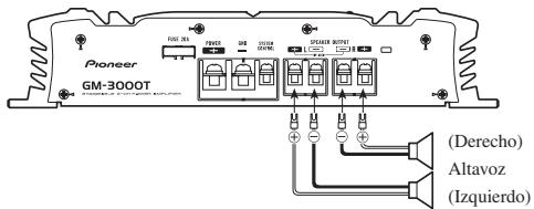
Modo de uno canal (mono)
Instalación
PRECAUCION
- No lo instale en:
—Donde podría lesionar al conductor o a los pasajeros si se detiene el vehículo brusca- mente.
—Donde podría interferir con el conductor, como por ejemplo en el piso en frente al asiento del conductor. - Asegúrese que los cables no se enganchen en el mecanismo deslizante de los asientos, resultando en cortocircuito.
- Confirme que ninguna parte quede detrás del panel, cuando perfore un orificio para la instalación del amplificador. Asegúrese de proteger todos los cables y equipos importantes, tales como líneas de combustibles, líneas de frenos y el cableado eléctrico.
- Instale los tornillos de conexión de manera tal que la punta del tornillo no toque ningún cable. Esto es importante para evitar que los cables se corten por vibración del automóvil, lo que podría causar un incendio.
- Para evitar choques eléctricos, no instale el amplificador en donde pueda entrar en contacto con líquidos.
- Para asegurar una instalación apropiada, utilice las partes suministradas de la manera especificada. Si se utiliza cualquier otra parte que no sean las suministradas, puede dañarse las partes internas del amplificador, o pueden aflojarse y el amplificador puede dejar de funcionar.
PRECAUCION:
Para evitar fallas de funcionamiento y/o lesiones
- Para asegurar la disipación de calor apropriada del amplificador, cuide de lo siguiente durante la instalación.
—Permita un espacio adecuado en la parte superior del amplificador para una ventilación apropiada.
—No cubra el amplificador con la cubierta de piso o alfombra. - No instale el amplificador cerca de una puerta en donde puede ser mojado por la lluvia.
- No instale el amplificador sobre superficies inestables como el tablero del neumático de repuesto.
- Confirme que ninguna parte quede detrás del panel, cuando perfore un orificio para la instalación del amplificador. Asegúrese de proteger todos los cables y equipos importantes, tales como líneas de combustibles, líneas de frenos y el cableado eléctrico.
- Realice primero conexiones provisorias y compruebe que el amplificador y el sistema operan adecuadamente.
- Para asegurar una instalación apropiada, utilice las partes suministradas de la manera especificada. Si se utiliza cualquier otra parte que no sean las suministradas, puede dañarse las partes internas del amplificador, o pueden aflojarse y el amplificador puede dejar de funcionar.
Ejemplo de instalación en la alfombra del piso o en el chasis
- Ubique el amplificador en la posición en donde va a ser instalado. Inserte los tornillos autoterrajantes suministrados (4 × 18 mm) en los orificios de los tornillos. Presione los tornillos con un destornillador de modo que puedan dejar puntos marcados de la posición en donde irán los orificios para la instalación.
- Perfore orificios de 2,5 mm de diámetro en el punto marcado, e instale el amplificador, ya sea en la alfombra o directamente en el chasis.
Tornillos autoterrajantes (4 × 18 mm)
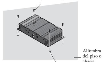
Perfore un orificio de 2,5 mm de diámetro
Especificaciones
Alimentación .... CC 14,4 V (10,8 — 15,1 V permisible)
Sistema de puesta a tierra .... Tipo negativo
Consumo de corriente 11,3 A (potencia continua, 4 Ω)
Consumo de corriente promedio* 3,8 A (4 Ω para dos canales) 5,9 A (4 Ω para uno canal)
Fusible 20 A
Dimensiones 300 (An) × 61 (Al) × 157 (Pr) mm
Peso 2,6 kg (No se incluyen los conductores para el cableado)
Potencia de salida máxima 80 W × 2 / 200 W × 1
Potencia de salida continua.... 40 W × 2 (en 14,4 V, 4 Ω, 20 — 20.000 Hz, 0,08% THD)
100 W × 1 (en 14,4 V, 4 Ω, 20 — 20.000 Hz, 0,8% THD)
50 W × 2 (en 14,4 V, 2 Ω, 20 — 20.000 Hz, 0,8% THD)
Impedancia de carga 4 Ω (2 — 8 Ω permisible)
(Acoplamiento en derivación: 4 — 8 Ω permisible)
Respuesta de frecuencia 10 — 45.000 Hz (+0 dB, -1 dB)
Relación de señal a ruido 100 dB (IEC-Red A)
Distorsión 0,008% (10 W, 1 kHz)
Separación de canales 55 dB (1 kHz)
Filtro de paso bajo ...... Frecuencia de corte: 80 Hz
Pendiente de corte: -12 dB/oct
Impedancia/nivel de entrada máxima ...... RCA: 6,5 V/22 kΩ (0,4 — 6,5 V)
Altavoz: 26 V/40 kΩ (1,6 — 26 V)
Nota:
- Las especificaciones y el diseño están sujetos a posibles modificaciones sin previo aviso debido a mejoramientos.
\*Consumo de corriente promedio
- El consumo de corriente promedio es casi el consumo de corriente máximo de esta unidad, cuando se ingresa una señal de audio. Utilice este valor cuando tenga que trabajar con la corriente total consumida por múltiples amplificadores de potencia.
- Owner's Manual
- GM-3000T
- Manual del Propietario
- PIONEER CORPORATION
- PIONEER ELECTRONICS (USA) INC.
- PIONEER EUROPE NV
- PIONEER ELECTRONICS ASIACENTRE PTE. LTD.
- PIONEER ELECTRONICS AUSTRALIA PTY. LTD.
- PIONEER ELECTRONICS OF CANADA, INC.
- PIONEER ELECTRONICS DE MEXICO, S.A. de C.V.
- Before Using This Product
- In case of trouble
- CAUTION
- WARNING
- Setting the Unit
- Gain Control
- LPF (Low-Pass Filter) Select Switch
- To prevent damage and/or injury
- Connecting the Power Terminal
- Pass the battery wire from the engine compartment to the interior of the vehicle.
- Twist the battery wire, ground wire and system remote control wire.
- Attach lugs to wire ends. Lugs not supplied.
- Connect the wires to the terminal.
- Connecting the Speaker Output Terminals
- Expose the end of the speaker wires using nippers or a cutter by about 10 mm and twist.
- Attach lugs to speaker wire ends. Lugs not supplied.
- Connect the speaker wires to the speaker output terminals.
- Using the Speaker Input
- ■ Connections when using the speaker input
- Connecting the Unit
- Connecting the Speaker wires
- Two-channel mode (stereo)
- One-channel mode (mono)
- Installation
- CAUTION:
- To prevent malfunction and/or injury
- Example of installation on the floor mat or on the chassis
- Specifications
- Note:
- \*Average current drawn
- Antes de usar este producto
- En caso de desperfectos
- PRECAUCION
- ADVERTENCIA
- Ajuste de esta unidad
- Control de ganancia
- Indicador de alimentación
- Interruptor BFC (Control de la frecuencia de batido)
- Interruptor de selección LPF (Filtro de paso bajo)
- PRECAUCION:
- Para evitar daños y/o lesiones
- Diagrama de conexión
- Conexión del terminal de alimentación
- Pase el cable de batería desde el compartimiento del motor al interior del vehículo.
- Tuerza el cable de batería, cable de puesta a tierra y cable de control remoto del sistema.
- Fije las orejetas a los extremos de los cables. Orejetas no suministrados.
- Conecte los cables al terminal.
- Conexión del terminal de salida de altavoz
- Fije las orejetas a los extremos de los cables de altavoz. Orejetas no suministrados.
- Conecte los cables de altavoz al terminal de salida de altavoz.
- Uso de la entrada de altavoz
- ■ Conexiones cuando se usa la entrada de altavoz
- Conexión de la unidad
- Conexión de los cables de altavoces
- Instalación
- Para evitar fallas de funcionamiento y/o lesiones
- Ejemplo de instalación en la alfombra del piso o en el chasis
- Especificaciones
- Nota:
- \*Consumo de corriente promedio
Marque : PIONEER
Modèle : GM-3000T
Catégorie : Amplificateur automobile