
EFA1020-1X - Aspirateur AEG-ELECTROLUX - Notice d'utilisation et mode d'emploi gratuit
Retrouvez gratuitement la notice de l'appareil EFA1020-1X AEG-ELECTROLUX au format PDF.
| Type de produit | Hotte aspirante / Purificateur d'air |
| Marque | AEG-ELECTROLUX |
| Modèle | EFA1020-1X |
| Dimensions (L x l) | 1000 x 700 mm |
| Poids | 31 kg |
| Alimentation | 230 V |
| Puissance | 272 W |
| Type de montage | Plafond, suspension par câble |
| Commandes | Télécommande et panneau 4 boutons |
| Éclairage | 2 ampoules halogènes 20 W |
| Filtre métal avec ioniseur | Oui, lavable |
| Filtre inox avec charbon actif | Oui, remplaçable |
| Lampe germicide UV-C | Oui |
| Détecteur de chaleur | Oui, arrêt automatique à 69-71°C |
| Distance minimale au plan de cuisson | 65 cm (gaz) / selon plaque |
| Niveaux de puissance | 3 niveaux + mode arrêt différé (10-40 min) |
| Entretien des filtres | Filtre métal : nettoyage toutes les 8-10 semaines ; charbon : remplacement 3-12 mois |
| Pièces détachées | Filtre charbon actif (réf. AK LRZ), ampoules halogènes |
| Garantie | 2 ans |
FOIRE AUX QUESTIONS - EFA1020-1X AEG-ELECTROLUX
Questions des utilisateurs sur EFA1020-1X AEG-ELECTROLUX
0 question sur cet appareil. Repondez a celles que vous connaissez ou posez la votre.
Poser une nouvelle question sur cet appareil
Téléchargez la notice de votre Aspirateur au format PDF gratuitement ! Retrouvez votre notice EFA1020-1X - AEG-ELECTROLUX et reprennez votre appareil électronique en main. Sur cette page sont publiés tous les documents nécessaires à l'utilisation de votre appareil EFA1020-1X de la marque AEG-ELECTROLUX.
MODE D'EMPLOI EFA1020-1X AEG-ELECTROLUX
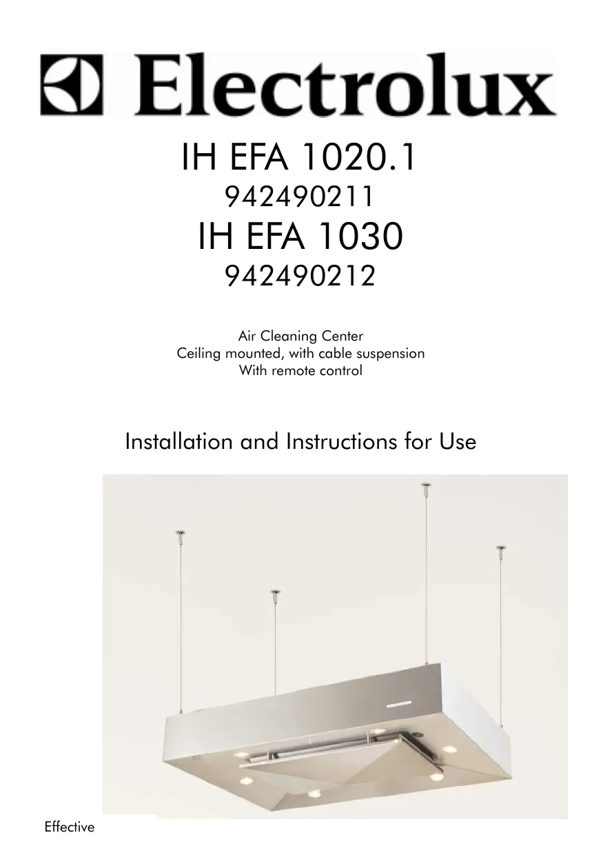
Electrolux
IH EFA 1020.1
942490211
IH EFA 1030
942490212
Air Cleaning Center
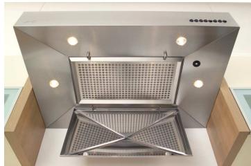
Ceiling mounted, with cable suspension
With remote control
Installation and Instructions for Use
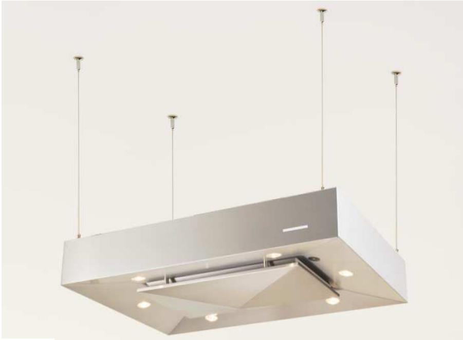
natural_image
Modern ceiling light fixture with vertical metal posts and a recessed ventilation grille (no text or symbols visible)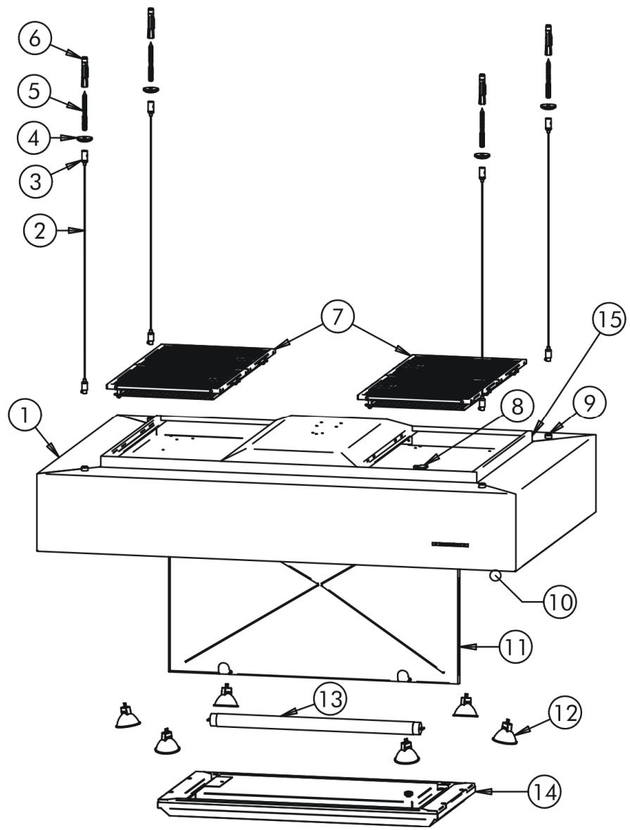
text_image
Technical diagram of a device assembly with numbered components for identification and assembly reference.- Hood body
- Cable suspension
- Cable support
- Decorative disc
- Hanger bolt
- Dowel
- Metal filter with ionizer sheet, with spring lock
- Cable for ionizer sheet
-
Receptacle for wire suspension
-
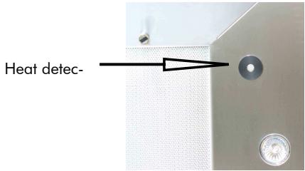
Heat detector
- Grease collector
- Halogen lamp 20 Watt
- Germicidal lamp (UV-C Lamp) EKL
- Stainless steel filter 586x324 mm incl. activated carbon
- Power cord outlet
EFA 1020.1/1030 Air Cleaning Center (Ceiling Mounted) with Cable Suspension
Installation Instructions—Instructions for Use
In order to be able to use your exhaust hood in the best possible manner, please read these intructions carefully and keep them in case they are needed.
1. Safety and General notes
- The exhaust hood can only be connected to a properly installed power outlet or connected directly by a professional. The power outlet must be as secure as possible directly in the junction box. The electrical data is found on the nameplate, after opening the grease collector (11), behind the stainless steel filter (14), in the interior of the device.
• The connection and commissioning may only be carried out by a professional. - Never use the exhaust hood without a filter (7/14) and open grease collector (11).
• Always use gas burners properly. - Accessible parts can become hot while cooking or when they are used with cooking utensils!
- The gas burner flames must always be covered with cookware. Strong heat development of open flames could damage the exhaust hood.
- The exhaust hood's power supply must be interrupted by pulling the plug before conducting any cleaning or maintenance work.
- Flambee dishes must not be prepared under the exhaust hood. The open flame could cause a fire.
- Never leave the pan unsupervised when frying food. The oil could start a fire.
- Constant maintenance ensures perfect operation and optimal performance of the exhaust hood.
- All contaminated surfaces should be cleaned of debris regularly. The filter must be removed and cleaned regularly. (see page 11).
• Incorrect halogen lamps (12) could ruin the transformer.
- The device can swing freely because it is attached to the ceiling with steel cables.
- Do not allow the heat sensor to react to a flame.
- Keep a minimum distance of 300 mm between the ceiling and the upper side of the hood.
- Minimum distance between the storage surface of the cooking vessels on the hob and the lowest part of the exhaust hood: This distance must be at least 65 cm if the exhaust hood is installed above a gas appliance. If the mounting instructions for the hob specify a greater distance, this distance is to be adhered to. This minimum distance also applies to electric stoves.
- This unit must not be used by persons, including children with reduced physical, sensory or mental abilities, or by persons without experience and knowledge unless they are supervised by a person who is responsible for their safety and has been instructed on the use of this equipment.
- Children must not be unsupervised in the vicinity of the unit and must not play with the unit under any circumstances.
• Safety Shutdown:
If one or more filters are removed, the unit switches off automatically. The unit is operational once again only after the correct positioning of the filter.
- CAUTION: Accessible parts may become hot when used with cooking appliances.
!!! Operate this unit only with inserted filters (7/14) and a closed grease collector (11) !!!
!!! Do not operate this unit without a filter (7/14) (High voltage and UV-C radiation) Do not look into the illuminated germicide lamp (13) !!!
2. Before Installation
- The following parts are in the package: hood body, stainless steel filter, accessory kit and cleaning kit (the cable suspensions are in the accessory kit).
- Check that the exhaust hood was not damaged during transport. If there is any damage, the unit must not be installed.
- Make sure that the installation and the electrical connections have been conducted by a qualified technician according to the specifications of the manufacturer and the official regulations.
- Make sure that a 3-wire power cable is present on the site which comes from the ceiling on the right side behind the cable suspension.
Caution: The electrical connection must be performed by a licensed electrician. The plug must be accessible after installation. A Type 12 or Type 13 power outlet is to be provided. The connection cable is 2.4 metres long.
Caution: If the unit is to be used with as a fixed connection rather than with the plug, a separator belonging to that only must be available.
Caution: The power supply to the hood must be unplugged before conducting maintenance work.
3. Installation
Caution!! The connection to the 230 Volt network as well as the entire installation of the exhaust hood must be at absolute zero potential and conducted by a professional.
- Workflow:
Carry the middle of the cooktop to the ceiling.
- Workflow:
Draw four drill holes on the ceiling and then drill the four holes. (Sketch 1 = IH EFA 1020.1;
Sketch 2 = IH EFA 1030)
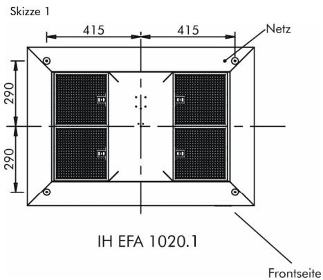
text_image
Skizze 1 415 415 Netz 290 290 IH EFA 1020.1 Frontseite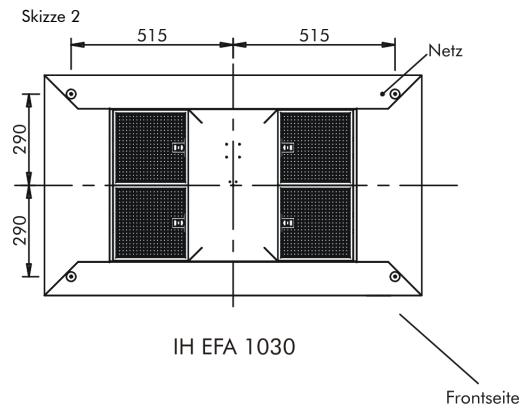
text_image
Skizze 2 515 515 Netz 290 290 IH EFA 1030 Frontseite- Workflow:
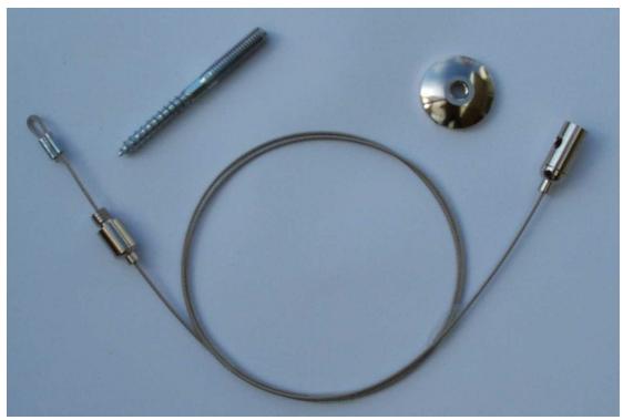
Take four dowels, four hanger bolts and four decorative discs from the accessories kit. Insert the four dowels, screw in the four hanger bolts, and screw the four decorative discs onto the hanger bolts.
- Workflow:
Now unpack the hood body.
- Workflow:
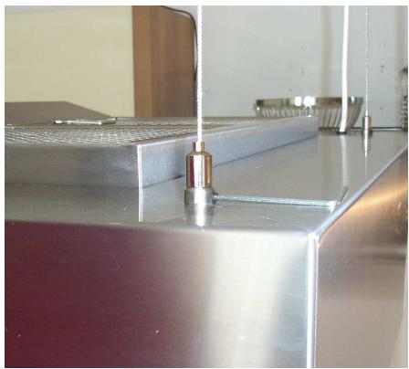
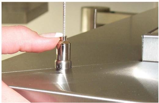
Thread the cable suspension with the cable clamp from above into the hood body. Screw the cable clamp into the mounting and secure with the set screw. One mounting per cable suspension.
- Workflow:
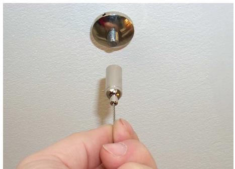
Now screw the four wire cables with the cable supports onto the hanger bolts. Now the steel cable can get twisted but it will ‘untwist’ during workflow 7.
- Workflow:
The wire cable relaxes and the length of the steel cable can be varied by exerting pressure onto the cable clamp. The hood can be aligned using a water level.
- Workflow:
Fasten the power cord of the hood to the feed line on site.
- Uncover the hood after installation only so that no dirt particles can reach the top of the hood.
The unit can be uncovered again only once the kitchen has been completely set up and the final cleaning has taken place.
Cable suspension with hanger bolt and decorative disc (located in accessories kit)
natural_image
Close-up of a metallic medical or electrical device with wires, a screw, and a circular component (no text or symbols visible)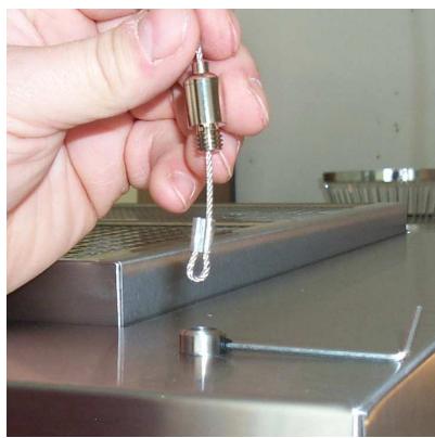
natural_image
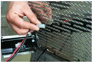
Close-up of a hand holding a metallic tool with a coiled spring attached to a metal panel (no visible text or symbols)Workflow 5
natural_image
Close-up of a metallic industrial component with a central metallic fixture and a vertical pipe inserted (no visible text or symbols)Workflow 5
natural_image
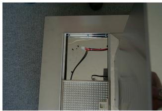
Hand inserting a cable into a wall-mounted socket (no text or symbols visible)Workflow 6
natural_image
Close-up of a hand holding a metal tool inserted into a stainless steel kitchen sink (no text or symbols visible)Workflow 7
4. Before Starting
• Make sure that the unit is disconnected from the power supply.
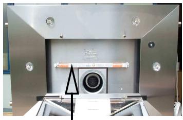
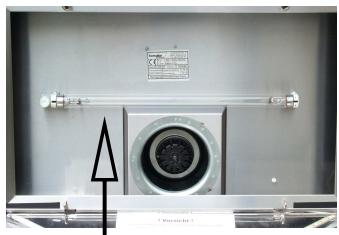
- Remove protective box from UV-C lamp (13)
- Insert the stainless steel filter (586x324 mm) (14) into the hood body (1)
Please ensure that the filter is correctly inserted! See photo below. All filters are equipped with a micro switch which interrupts the hood's electrical circuit power when it is incorrectly positioned!
- Close the drip collector (11)
The unit is now operational!
natural_image
Interior view of a stainless steel industrial enclosure with a central circular component and control panel (no visible text or symbols)UV-C Lamp with protective
natural_image
Interior view of a mechanical or electrical enclosure with a central circular component and metal fittings (no visible text or symbols)UV-C Lamp without protective carton
natural_image
Interior view of a stainless steel kitchen or oven with ventilation grilles and mounting fixtures (no visible text or symbols)Hood body with stainless steel filter
text_image
Heat detec-Insert filter correctly:
natural_image
Pure mechanical diagram showing a lever and support structure without any text, numbers, or symbols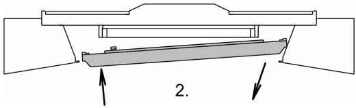
text_image
2.
text_image
3. 4.5. Operation
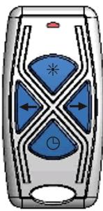
4-button control pad:

Hand transmitter:
natural_image
Diagram of a mobile phone interface with four blue X-shaped buttons and directional arrows (no text or symbols)Switch on to level 1: button →
Switch up to next level: button →
With the button, you switch the hood to level 1, pressing several times switches the hood to level 2, 3, and then off again.
With the button, you switch the hood to level 3, pressing the button several times in a row switches the hood to levels 2, 1 and 0
After run time button:

After pressing this button, the hood works with the set level in after run. There are four after run times which you can select by pressing the appropriate button. Press once = 10 minutes (the light bar/s flash/flashes once), press twice = 20 minute (the light bar/s flash/flashes twice), press three times = 30 minute (the light bar/s flash/flashes three times) and press four times = 40 minutes (the light bar/s flash/flashes four times). The fan speed can be increased or decreased during the after run time.
Light button:

By pressing once briefly, the right and left halogen lamp is switched on or off. If the button is pressed for a longer period of time, both halogen lamps at the front and the back are switched on or off.
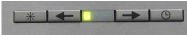
6. Programming Instructions: Hand Transmitter
4-button control pad:
Hold down simultaneously until the green LED on the control panel lights up. Then let go of both buttons at the same time.
text_image
Control panel with icons including star, left arrow, yellow square, right arrow, and clock symbolHand Transmitter:
Press the light button ✪ on the hand transmitter until the light goes on or off.
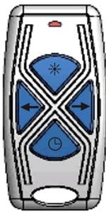
natural_image
Diagram of a stylized device with blue geometric shapes and directional arrows, no text or symbols present.The new hand transmitter is programmed to the existing exhaust hood.
7. Switching the halogen reflector lamps (12)
Take out defective halogen reflector lamps (12) and press the new lamps into the socket! Do not loosen the halogen lamps with metal objects (e.g. screwdriver or knife) because they could scratch the hood body.
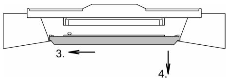
8. Removing the Metal Filter with the Ionizer Sheet (7)
The unit must be disconnected from the mains before removing the metal filter!
When removing the upper metal filter (7) the following must be noted:
In order to be able to clean the ionizer sheet, the supply cable from each filter must be detached when removing the filter. For this, the cable only must be removed (see the following photos).
natural_image
Close-up of a hand holding a small white object next to a metal panel with wires and connectors (no visible text or symbols)Supply cable is removed from ionizer sheet
natural_image
Interior view of an electronic device showing exposed wiring and components (no visible text or symbols)View after removal of metal filter
!! When inserting the metal filter, please note that the snap locks must point to the center of the hood !!
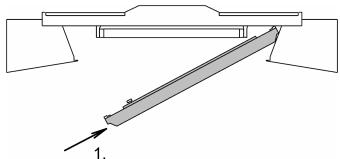
9. Removing the stainless steel filter (14)
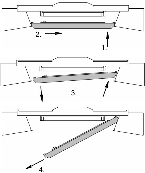
text_image
2. 1. 3. 4.Page 10
10. Filter Cleaning and Care
Cleaning the outside of the stainless steel exhaust hood:
A care lotion for cleaning and care is included with each unit. Moisten a soft cloth and apply to unit with light pressure, let dry and then polish in the brushing direction.
! It is very important to take note of the "brushing direction" when handling stainless steel devices!
Interior Cleaning:
The unit must be disconnected from the mains before it is opened!
When changing the activated carbon or cleaning the metal grease filter (7/14), clean the accessible housing parts of grease deposits. This way, the risk of fire is minimized and optimal function is maintained. Please wash with a degreasing detergent and damp cloth only.
Filter:
Caution! With increasing saturation of fatty residues, the risk of fire increases and the function of the unit can be impaired.
! Clean the metal filter (7/14) as needed!
Remove the activated carbon insert and the thumb screws before cleaning!
The metal grease filter (7/14) must be cleaned every 8 to 10 weeks under normal operating conditions (2-3 hours daily) Cleaning should be done with the cleaner which is included with the exhaust hood however the cleaning can be done in the dishwasher depending on the size of the filter. The cleaning intervals for the metal filter (7) on the top side of the hood body are shorter during the heavy pollen season. The inner layers of the metal fat filter (7) are made of aluminum. It resists chemical influences (corrosion resistance). However, it can be attacked by soda and caustic sode so that a brown discoloration can occur. The frame and the cover sheet of this metal filter is made of stainless steel.
Do not wash metal grease filters (7/14) with other dishes.
When cleaning by hand, rinse the filter several times in hot, soapy water.
Exchanging activated carbon
The unit must be disconnected from the mains before it is opened!
Activated carbon is used to bind ordorants. The frequency with which the activated carbon is to be exchanged is between three months and one year, depending on frequency of use. The used carbon can be disposed of in the normal household waste.
• Make sure unit is not connected to the mains and without current!
• Fold grease collector (11) down
- Remove stainless steel filter (14)
- Loosen the two thumb screws
- Remove stainless steel frame and then remove carbon cartridge
- Loosen the two thumb screws again on the carbon cartridge and then replace the old carbon with the new carbon
• Tighten the previously loosened thumb screws
- Insert the stainless steel filter (14) into the hood body
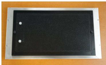
natural_image
Rectangular black perforated panel mounted on a metal frame, placed on an orange surface (no text or symbols visible)Stainless steel filter with carbon cartridge (rear side)
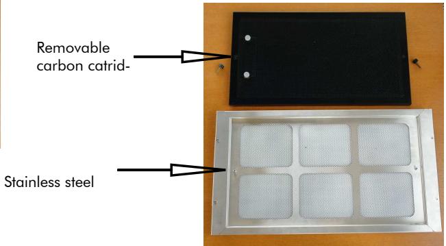
text_image
Removable carbon catrid- Stainless steel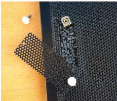
natural_image
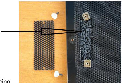
Close-up of a textured black mesh panel with small white bolts and a small square marker, placed on a wooden surface (no text or symbols visible)For loose activated carbon
natural_image
Top-down view of a perforated metal plate with embedded bolts and small components, no text or symbols visible11. What to do if...."
Hood crackles:
Sporadic hood crackling is normal. It shows that the air is being
cleaned by the ionizer. In case of prolonged crackling, the upper metal filter and ionizer sheet must be cleaned. In addition, you should check whether the extension cord plug has been connected horizontally to the ionizer sheet.
The hood cannot be shut off:
Check that all filters have been inserted correctly, that each filter is equipped with a microswitch which will interrupt the electrical circuit when incorrectly positioned.
12. Service
The well-trained customer service of Electrolux is available to all of our customers.
Before you contact customer service:
Make sure that there have not been any errors in operation.
Check your exhaust hood according to the chapter "What to do if..."
If you contact customer service:
Make note of the following information which can be found on the unit's nameplate:
- Serial number
- Model name
• Product number
Please provide this information for:
- Customer service requests
- Spare part or accessory orders
• Technical questions
The nameplate is found in the hood body behind the filter
• Making a precise note of your observations will make the preparations and the work for our
service technicians easier.
- Call the service number 0848 848 111. Your call will automatically be routed to the nearest service center.
- Please be at home when the service technician comes because he needs your information.
13. Spare Parts-Accessories:
Activated carbon refill pack 1 kg,
A.-Nr. AK LRZ (893573850)
14. Quality Control
The units are subject to the following tests according to VDE 0701 Teil 1 and EN60335-1:
- Protective wire test
• High voltage test - Insulation test
• Function and performance test
• Mechanical visual inspection
In addition, a visual inspection is conducted and the accessories are checked for completeness.
This product is in compliance with
- The security objectives of the "Low Voltage" guideline EG/73/23
- The protection requirements of the "EMC" EG/336/89 guideline as amended by EG/68/93 guideline, built and brought onto the market.
KUNDENDIENST
Electrolux
| Servicestellen | Points de service | Servizio dopo vendita | Point of service |
| 5506 Mägenwil/Zürich Industriestr. 10 | |||
| 9000 St. Gallen Zürcherstrasse 204 e | |||
| 4052 Basel St. Jakob-Turm Birsstrasse 320B | |||
| 6020 Emmenbrücke Seetalstrasse 11 | |||
| 7000 Chur Comercialstrasse 19 | |||
| 3018 Bern Morgenstrasse 131 | |||
| 1028 Préverenges Le Trési 6 | |||
| 6916 Grancia Zona Industriale E |
Ersatzteilverkauf / Point de vente de rechange / Vendita pezzi di ricambio / spare parts service
| 5506 Mägenwil, Industriestrasse 10, Tel. 0848 848 023 | |
| Fachberatung, Verkauf/Demonstration, Vente/Consulente (cucina), Vendita/consulting, sales | |
| 8048 Zürich, Badenerstrasse 587, Tel. 044 405 81 11 | |
| Garantie | Für jedes Produkt gewähren wir ab Verkauf bzw. Lieferdatum an den Endverbraucher eine Garantie von 2 Jahren. (Ausweis durch Garantieschein, Faktura oder Verkaufsbeleg).Die Garantieleistung umfasst die Kosten für Material, Arbeits- und Reisezeit.Die Garantieleistung entfällt bei Nichtbeachtung der Gebrauchsanweisung und Betriebsvorschriften, unsachgerechter Installation, sowie bei Beschädigung durch äussere Einflüsse, höhere Gewalt, Eingriffe Dritter und Verwendung von Nicht-Original Teilen. |
| Garantie | Nous octroyons sur chaque produit 2 ans de garantie à partir de la date de livraison ou de la mise en service au consommateur (documenté au moyen d'une facture, d'un bon de garantie ou d'un justificatif d'achat). Notre garantie couvre les frais de mains d'œuvres et de déplacement, ainsi que les pièces de rechange.Les conditions de garantie ne sont pas valables en cas d'intervention d'un tiers non autorisé, de l'emploi de pièces de rechange non originales, d'erreurs de maniement ou d'installation dues à l'inobser-vation du mode d'emploi, et pour des dommages causés par des influences extérieures ou de force majeure. |
| Garanzia | Per ogni prodotto concediamo una garanzia di 2 anni a partire dalla data di consegna o dalla sua messa in funzione. (fa stato la data della fattura, del certificato di garanzia o dello scontrino d'acquisto) Nella garanzia sono comprese le spese di manodopera, di viaggio e del materiale.Dalla copertura sono esclusi il logoramento ed i danni causati da agenti esterni, intervento di terzi, utilizzo di ricambi non originali o dalla inosservanza delle prescrizioni d'installazione ed istruzioni per l'uso. |
| Warranty | For each product we provide a two-year guarantee from the date of purchase or delivery to the consumer (with a guarantee certificate, invoice or sales receipt serving as proof).The guarantee covers the costs of materials, labour and travel.The guarantee will lapse if the operating instructions and conditions of use are not adhered to, if the product is incorrectly installed, or in the event of damage caused by external influences, force majeure, intervention by third parties or the use of non-genuine components. |
16. Information
Information on the Heat Detector (10):
We care about your safety. For this reason, we have installed a heat detector into the air cleaning center which functions as follows.
If a temperature between 69^ C and 71^ C is reached under the exhaust hood, the alarm rings automatically and the unit's power supply is interrupted. Once it cools down to approx. 30^-35^ C the alarm is again silenced automatically.
Ionizer Information:
The ionizer makes the air fresher. The negative ions clean the air of very fine dust particles, from bacteria which is suspended in the air on positive ions, floating viruses and fungal spores. The airstream produced by the built-in motor leads particles to a metal filter and settles them there. These deposits are removed with regular cleaning of the upper metal filter (3).
The use of the ionizer is not dangerous! Even a high dose of negative ions is not damaging to health. A high dose of positive ions, however, can make one ill, tired, weak, and in many cases even irritable and aggressive.
Germicidal Lamp Information (13):
Germicidal lamps are special low-pressure mercury lamps with short wavelength ultraviolote radiation whose disinfecting effect of natural sunlight is far superior. It destroys all effective microorganisms such as bacteria, viruses, spores. Yeasts, algae, protozoa and mildews...and all of this without ozone!
!! Never look into a lamp which is switched on because UV C radiation damages the eyes!!
WARNING:
Touching with bare hands causes stains. Always use a clean cloth or clean gloves!
If the quartz glass comes into contact with the hands, it must be cleaned with a little alcohol before bringing the lamp back into use.
17. Notes for the Correct Disposal of the Product
DISPOSAL
Packaging Material

Packaging materials are environmentally friendly and recyclable. The plastic parts are labelled, e. g. >PE<, >PS< etc. Dispose of the packaging materials at the community waste collection point in the collection containers provided according to their labelling.
Old Device

The symbol 📋 on the product or the product's packaging indicates that this product is not to be 📋 treated as normal household waste but must be given up to a collection point for the recycling of electrical and electronic equipment. Your contribution to the proper disposal of this product protects the environment and human health. The environment and health are put at risk by incorrect disposal. More information about recycling this product can be found at your city hall, refuse collection or the business where this product was purchased.

Where does the old equipment go?
Anywhere where new equipment is sold or disposal at the official S.EN.S collection points or official S.EN.S-Recyclers.
The list of the official S.EN.S-Recyclers can be found at www.sens.ch.

Warning: In order to ensure that used equipment is no longer hazardous, render it unusable before disposal. Remove the equipment from the mains supply also and remove the power supply cable from the equipment.
18. Technical Data
Outside dimensions:
Minimum distance to cooking surface:
Supply voltage:
Power consumption:
Total weight:
1000 x 700 mm or 1200 x 700 mm
700 mm
230 Volts
272 Watts
IH EFA 1020.1—31 kg
ICH EFA 1030—34 kg