MODE D'EMPLOI DSP-A3090 YAMAHA
YAMAHA
DSP.A3090
DIGITAL SOUND FIELD PROCESSING AMPLIFIER
AMPLIFICATEUR DE TRAITEMENT DE CHAMP SONORE NUMERIQUE
text_image
YAMAHA NATURAL SOUND DIGITAL SOUND FIELD PROCESSING AMPLIFIER DSP-A3050
CINEMA DIP 7.16
TALW BIRNING
SP-45 VOLTAGE
POWER
PROCESSOR
STOCK
THIRD LIME
DISP
OUT 5 kHz
AC-2 PCM
TYPE 2
MONITOR
INPUT TRIM
SET MENU
PROGRAM
EFFECT INPUT MODE
PHONES
VIDEO AUX
BASS EXTENSION
DASS
TREBLE
BALANCE
REC OUT
VBR 1
VBR 2
VBR 3
VBR 4
VBR 5
VBR 6
VBR 7
VBR 8
VBR 9
VBR 10
VBR 11
VBR 12
VBR 13
VBR 14
VBR 15
VBR 16
VBR 17
VBR 18
VBR 19
VBR 20
VBR 21
VBR 22
VBR 23
VBR 24
VBR 25
VBR 26
VBR 27
VBR 28
VBR 29
VBR 30
VBR 31
VBR 32
VBR 33
VBR 34
VBR 35
VBR 36
VBR 37
VBR 38
VBR 39
VBR 40
VBR 41
VBR 42
VBR 43
VBR 44
VBR 45
VBR 46
VBR 47
VBR 48
VBR 49
VBR 50
VBR 51
VBR 52
VBR 53
VBR 54
VBR 55
VBR 56
VBR 57
VBR 58
VBR 59
VBR 60
VBR 61
VBR 62
VBR 63
VBR 64
VBR 65
VBR 66
VBR 67
VBR 68
VBR 69
VBR 70
VBR 71
VBR 72
VBR 73
VBR 74
VBR 75
VBR 76
VBR 77
VBR 78
VBR 79
VBR 80
VBR 81
VBR 82
VBR 83
VBR 84
VBR 85
VBR 86
VBR 87
VBR 88
VBR 89
VBR 90
VBR 91
VBR 92
VBR 93
VBR 94
VBR 95
VBR 96
VBR 97
VBR 98
VBR 99
VBR 100
OPERATION MANUAL
MODE D'EMPLOI
PRECAUTIONS & SAFETY INSTRUCTIONS
text_image
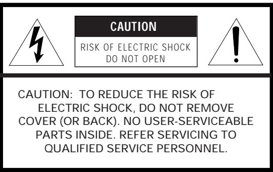
CAUTION
RISK OF ELECTRIC SHOCK
DO NOT OPEN
CAUTION: TO REDUCE THE RISK OF
ELECTRIC SHOCK, DO NOT REMOVE
COVER (OR BACK). NO USER-SERVICEABLE
PARTS INSIDE. REFER SERVICING TO
QUALIFIED SERVICE PERSONNEL.
- Explanation of Graphical Symbols
The lightning flash with arrowhead symbol, within an equilateral triangle, is intended to alert you to the presence of uninsulated “dangerous voltage” within the product’s enclosure that may be of sufficient magnitude to constitute a risk of electric shock to persons.

The exclamation point within an equilateral triangle is intended to alert you to the presence of important operating and maintenance (servicing) instructions in the literature accompanying the appliance.
WARNING
TO REDUCE THE RISK OF FIRE OR ELECTRIC SHOCK, DO NOT EXPOSE THIS UNIT TO RAIN OR MOISTURE.
IMPORTANT!
Please record the serial number of this unit in the space below.
Model:
Serial No.:
The serial number is located on the rear of the unit.
Retain this Owner's Manual in a safe place for future reference.
SAFETY INSTRUCTIONS
1 Read Instructions – All the safety and operating instructions should be read before the unit is operated.
2 Retain Instructions – The safety and operating instructions should be retained for future reference.
3 Heed Warnings – All warnings on the unit and in the operating instructions should be adhered to.
4 Follow Instructions – All operating and other instructions should be followed.
5 Water and Moisture – The unit should not be used near water – for example, near a bathtub, washbowl, kitchen sink, laundry tub, in a wet basement, or near a swimming pool, etc.
6 Carts and Stands – The unit should be used only with a cart or stand that is recommended by the manufacturer.
6A A unit and cart combination should be moved with care. Quick stops, excessive force, and uneven surfaces may cause the unit and cart combination to overturn.
7 Wall or Ceiling Mounting – The unit should be mounted to a wall or ceiling only as recommended by the manufacturer.

8 Ventilation – The unit should be situated so that its location or position does not interfere with its proper ventilation. For example, the unit should not be situated on a bed, sofa, rug, or similar surface, that may block the ventilation openings; or placed in a built-in installation, such as a bookcase or cabinet that may impede the flow of air through the ventilation openings.
9 Heat – The unit should be situated away from heat sources such as radiators, stoves, or other appliances that produce heat.
10 Power Sources – The unit should be connected to a power supply only of the type described in the operating instructions or as marked on the unit.
11 Power-Cord Protection – Power-supply cords should be routed so that they are not likely to be walked on or pinched by items placed upon or against them, paying particular attention to cords at plugs, convenience receptacles, and the point where they exit from the unit.
12 Cleaning – The unit should be cleaned only as recommended by the manufacturer.
13 Nonuse Periods – The power cord of the unit should be unplugged from the outlet when left unused for a long period of time.
14 Object and Liquid Entry – Care should be taken so that objects do not fall into and liquids are not spilled into the inside of the unit.
15 Damage Requiring Service – The unit should be serviced by qualified service personnel when:
A. The power-supply cord or the plug has been damaged;
or
B. Objects have fallen, or liquid has been spilled into the unit;
or
C. The unit has been exposed to rain;
or
D. The unit does not appear to operate normally or exhibits a marked change in performance;
or
E. The unit has been dropped, or the cabinet damaged.
16 Servicing – The user should not attempt to service the unit beyond those means described in the operating instructions. All other servicing should be referred to qualified service personnel.
17 Power Lines – An outdoor antenna should be located away from power lines.
18 Grounding or Polarization – Precautions should be taken so that the grounding or polarization is not defeated.
- IMPORTANT NOTICE : DO NOT MODIFY THIS UNIT!
This product, when installed as indicated in the instructions contained in this manual, meets FCC requirements. Modifications not expressly approved by Yamaha may void your authority, granted by the FCC, to use the product.
-
IMPORTANT : When connecting this product to accessories and/or another product use only high quality shielded cables. Cable/s supplied with this product MUST be used. Follow all installation instructions. Failure to follow instructions could void your FCC authorization to use this product in the USA.
-
NOTE : This product has been tested and found to comply with the requirements listed in FCC Regulations, Part 15 for Class “B” digital devices. Compliance with these requirements provides a reasonable level of assurance that your use of this product in a residential environment will not result in harmful interference with other electronic devices.
This equipment generates/uses radio frequencies and, if not installed and used according to the instructions found in the users manual, may cause interference harmful to the operation of other electronic devices.
Compliance with FCC regulations does not guarantee that interference will not occur in all installations. If this product is found to be the source of interference, which can be determined by turning the unit “OFF” and “ON”, please try to eliminate the problem by using one of the following measures:
Relocate either this product or the device that is being affected by the interference.
Utilize power outlets that are on different branch (circuit breaker or fuse) circuits or install AC line filter/s.
In the case of radio or TV interference, relocate/reorient the antenna. If the antenna lead-in is 300 ohm ribbon lead, change the lead-in to coaxial type cable.
If these corrective measures do not produce satisfactory results, please contact the local retailer authorized to distribute this type of product. If you can not locate the appropriate retailer, please contact Yamaha Electronics Corp., U.S.A. 6660 Orangethorpe Ave, Buena Park, CA 90620.
The above statements apply ONLY to those products distributed by Yamaha Corporation of America or its subsidiaries.
PRECAUTIONS
- AVOID EXCESSIVE HEAT, HUMIDITY, DUST AND VIBRATION
Keep the unit away from locations where it is likely to be exposed to high temperatures or humidity—such as near radiators, stoves, etc. Also avoid locations which are subject to excessive dust accumulation or vibration which could cause mechanical damage.
- INSTALL THE UNIT IN WELL-VENTILATED CONDITION
The openings on the cabinet assure proper ventilation of the unit. If these openings are obstructed, the temperature inside the cabinet will rise rapidly. Therefore, avoid placing objects against these openings, and install the unit in well-ventilated condition. Make sure to allow a space of at least 10 cm behind and on the both sides and at least 20 cm above the top panel of the unit. Otherwise it may not only damage the unit, but also cause fire.
- KEEP THE AC POWER PLUG
DISCONNECTED DURING VACATION ETC.
When not planning to use this unit for long periods of time (ie., vacation, etc.), disconnect the AC power plug from the wall outlet.
- AVOID PHYSICAL SHOCKS
Strong physical shocks to the unit can cause damage. Handle it with care.
- DO NOT OPEN THE UNIT OR ATTEMPT REPAIRS OR MODIFICATIONS YOURSELF
This product contains no user-serviceable parts. Refer all maintenance to qualified Yamaha service personnel. Opening the unit and/or tampering with the internal circuitry will make servicing difficult and will endanger you and your unit.
- DO NOT OPERATE THE UNIT UPSIDE-DOWN
Do not operate the unit upside-down. It may overheat, possibly causing damage.
- HANDLE THE UNIT GENTLY AND CAREFULLY
Do not use force on switches, knobs or cords. When moving the set, first turn the unit off. Then gently disconnect the power plug and the cords connecting to other equipment. Never pull the cord itself.
- ALWAYS SET THE VOLUME CONTROL TO MINIMUM
Always set the volume control to “ - ” before starting audio source play. Increase the volume gradually to an appropriate level after playback has been started.
- MAKE SURE POWER IS OFF BEFORE MAKING OR REMOVING CONNECTIONS
Always turn power OFF prior to connecting or disconnecting cables. This is important to prevent damage to the unit itself as well as other connected equipment.
- HANDLE CABLES CAREFULLY
Always plug and unplug cables—including the AC cord—by gripping the connector, not the cord.
- CLEAN WITH A SOFT DRY CLOTH
Never use solvents such as benzine or thinner to clean the unit. Wipe clean with a soft, dry cloth.
- KEEP AWAY FROM TUNERS
Digital signals generated by the unit may interfere with other equipment such as tuners, receivers or TVs. Move the system farther away from such equipment if interference is observed.
- READ THE "TROUBLESHOOTING" SECTION
Be sure to read the “Troubleshooting” section on common operating errors before concluding that your unit is faulty.
- ABOUT THE AC OUTLETS
Do not connect audio equipment to the AC outlets on the rear panel if that equipment requires more power than the outlets are rated to provide.
We Want You Listening For A Lifetime (for US customers only)
YAMAHA and the Electronic Industries Association's Consumer Electronics Group want you to get the most out of your equipment by playing it at a safe level.
One that lets the sound come through loud and clear without annoying blaring or distortion – and, most
importantly, without affecting your
sensitive hearing. Since hearing damage from loud sounds is often undetectable until it is too late,
YAMAHA and the Electronic Industries
Association's Consumer Electronics
Group recommend you to avoid
prolonged exposure from excessive volume levels.

LISTENING For A Lifetime
CAUTION (FOR CANADA MODEL)
TO PREVENT ELECTRIC SHOCK, MATCH WIDE BLADE OF PLUG TO WIDE SLOT AND FULLY INSERT.
FOR CANADIAN CUSTOMER
THIS CLASS B DIGITAL APPARATUS MEETS ALL REQUIREMENTS OF THE CANADIAN INTERFERENCE-CAUSING EQUIPMENT REGULATIONS.
This product complies with the radio frequency interference requirements of the Council Directive 82/499/EEC and/or 87/308/EEC.
The apparatus is not disconnected from the AC power source as long as it is connected to the wall outlet, even if the apparatus itself is turned off.
Congratulations!
You are the proud owner of a Yamaha Digital Sound Field Processing (DSP) System—an extremely sophisticated audio component. The DSP system takes full advantage of Yamaha’s undisputed leadership in the field of digital audio processing to bring you a whole new world of listening experiences. Follow the instructions in this manual carefully when setting up your system, and the DSP system will sonically transform your room into a wide range of listening environments—anything from a famous concert hall to a cozy jazz club. In addition, you get incredible realism from Dolby-Surround encoded video sources using the built-in Dolby Pro Logic Surround Decoder and Dolby Surround AC-3 Decoder.
Seven built-in channels of amplification on the DSP-A3090 mean that no additional amplifiers are required to enjoy advanced digital sound field processing.
Rather than tell you about the wonders of digital sound field processing, however, let's get right down to the business of setting up the system and trying out its many capabilities. Please read this operation manual carefully and store it in a safe place for later reference.
CONTENTS
PRECAUTIONS & SAFETY INSTRUCTIONS
...Inside the front cover
GETTING STARTED....3
FEATURES....5
SPEAKER SETUP ....10
CONTROLS & THEIR FUNCTIONS....13
FRONT PANEL....13
REMOTE CONTROL UNIT....16
CONNECTIONS 18
REAR PANEL PARTS AND THEIR FUNCTIONS....18
REAR PANEL SWITCH AND CONTROL SETTINGS ....21
GENERAL INSTRUCTIONS FOR CONNECTIONS......21
CONNECTING AUDIO/VIDEO SOURCE EQUIPMENT
TO THIS UNIT....22
CONNECTING SPEAKER SYSTEMS 26
SELECTING THE OUTPUT MODES SUITABLE FOR YOUR SPEAKER SYSTEM....30
ADJUSTMENTS BEFORE OPERATION ....33
MAIN/CENTER/EFFECT SPEAKER LEVEL BALANCE
ADJUSTMENT....33
INPUT LEVEL ADJUSTMENT 35
ADJUSTMENTS IN THE "SET MENU" MODE ....36
GENERAL OPERATION......45
PLAYING A SOURCE....45
RECORDING A SOURCE TO AUDIO/VIDEO TAPE (OR DUBBING FROM A TAPE TO ANOTHER)......48
SELECTING SOUND FIELD PROGRAMS....49
MUTING THE EFFECT SOUND....51
SUPERIMPOSED VIDEO PROGRAM/PARAMETER
DISPLAY ....51
DESCRIPTIONS OF THE SOUND FIELD PROGRAMS......52
CREATING YOUR OWN SOUND FIELDS ....58
SELECTING AND EDITING PROGRAM PARAMETERS ....58
DESCRIPTIONS OF THE DIGITAL SOUND FIELD PARAMETERS....60
REMOTE CONTROL LEARNING FUNCTION....64
TROUBLESHOOTING....66
SPECIFICATIONS......68
GETTING STARTED
Unpacking
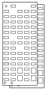
If you haven't already done so, carefully remove this unit and its accessories from the box and wrapping material. You should find the unit itself and the following accessories.
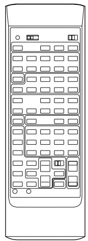
natural_image
Front view of a remote control panel with multiple slots and buttons (no text or symbols)
Remote control
natural_image
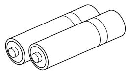
Line drawing of two cylindrical batteries (no text or symbols)
Batteries
natural_image
Pure electrical circuit lines without any symbols
User program sheets
Installing the Remote Control Unit Batteries
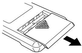
Since the remote control unit will be used for many of this unit's control operations, you should begin by installing the supplied batteries.
- Turn the remote control unit over and slide the battery compartment cover downward in the direction of the arrow.
natural_image
Diagram of a vehicle's rearview and side profile showing a triangular component with an arrow indicating direction (no text or symbols)
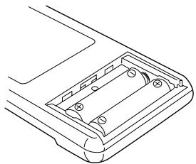
- Insert the batteries (LR6, AA, UM-3 type), being careful to align them with the polarity markings on the inside of the battery compartment.
natural_image
Line drawing of a mechanical component with internal cavities and mounting holes (no text or symbols)
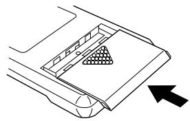
- Close the battery compartment cover.
natural_image
Diagram of a car interior showing a triangular grille and directional arrow (no text or symbols)
Notes about the Remote Control Unit
- When you notice that remote control operation has become erratic, or the distance from which the remote control will function has decreased, it's time to replace the batteries. Always replace all batteries at the same time.
* If you have exchanged batteries in the remote control unit with new ones, press the RESET button before using the remote control unit.
- Make sure that the YPC/USER/LEARN switch on the remote control unit is set to the YPC or USER position for normal operation.
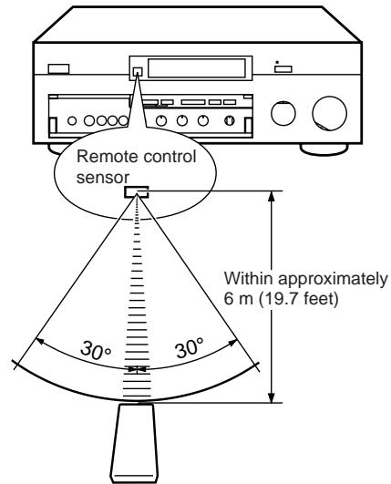
- This remote control uses an advanced, highly directional infrared beam. Be sure to aim the remote control directly at the remote control sensor on the main unit when operating.
Remote control transmitter operation range
text_image
Remote control
sensor
Within approximately
6 m (19.7 feet)
30°
30°
Notes
- There should be no large obstacles between the remote control transmitter and the main unit.
- If the remote control sensor is directly illuminated by strong lighting (especially an inverter type of fluorescent lamp etc.), it might cause the remote control transmitter to work incorrectly. In this case, reposition the main unit to avoid direct lighting.
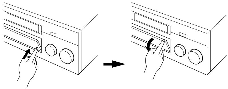
Open/close the control door
When it is not necessary to operate controls inside the control door, close the door.
To open the door
text_image
Diagram showing hand positioning of a device with labeled buttons and directional arrows indicating movement or adjustment.
To close the door
natural_image
Line drawing of a hand inserting a button into a rack-mounted device (no text or symbols)
FEATURES
This unit incorporates a sophisticated, multi-program digital sound field processor. The processor allows you to electronically expand and change the shape of the audio sound field from both audio and video sources, creating a theater-like experience in your listening room. This unit has a total of 12 digital sound field processor (DSP) modes. You can create an excellent audio sound field by selecting a suitable sound field (this will, of course, depend on what you will be listening to), and adding desired adjustments.
In addition, this unit incorporates a Dolby Pro Logic Surround decoder and Dolby Surround AC-3 decoder for multi-channel sound reproduction of Dolby Surround encoded video sources. The operation of the Dolby Pro Logic Surround or Dolby Surround AC-3 decoder can be controlled by selecting a corresponding DSP program including combined operations of the Yamaha DSP and the Dolby Pro Logic Surround or Dolby Surround AC-3 decoder.
Digital Sound Field Processing
What is it that makes live music so good? Today's advanced sound reproduction technology lets you get extremely close to the sound of a live performance, but chances are you'll still notice something missing, the acoustic environment of the live concert hall. Extensive research into the exact nature of the sonic reflections that create the ambience of a large hall has made it possible for Yamaha engineers to bring you this same sound in your own listening room, so you'll feel all the sound of a live concert. What's more, our technicians, armed with sophisticated measuring equipment, have even made it possible to capture the acoustics of a variety of actual concert halls, jazz clubs, theaters, etc. from around the world, to allow you to accurately recreate any one of these live performance environments, all in your own home.
Dolby Pro Logic Surround
This unit employs a Dolby Pro Logic Surround decoder similar to professional Dolby Stereo decoders used in many movie theaters. By using the Dolby Pro Logic Surround decoder, you can experience the dramatic realism and impact of Dolby Surround movie theater sound in your own home. Dolby Pro Logic employs a four channel five speaker system. The Pro Logic Surround system divides the input signal into four levels: the left and right main channels, the center channel (used for dialog), and the rear surround sound channels (used for sound effects, background noise, and other ambient noises). The center channel allows listeners seated in even less-than-ideal positions to hear the dialog originating from the action on the screen while experiencing good stereo imaging. Dolby Surround is encoded on the sound track of pre-recorded video tapes, laser discs, and some TV/cable broadcasts. When you play a source encoded with Dolby Surround on this unit, the Dolby Pro Logic Surround decoder decodes the signal and distributes the surround-sound effects.
This Dolby Pro Logic Surround Decoder employs a digital signal processing system. This system improves the stability of sound at each channel and crosstalk between channels, so that positioning of sounds around the room is more accurate compared with conventional analog signal processing systems.
In addition, this unit features a built-in automatic input balance control. This always assures you the best performance without manual adjustment.
Dolby Surround AC-3
The built-in Dolby Surround AC-3 Decoder leads you into a totally new sound experiences.
Dolby Surround AC-3 is a new generation of multi-channel digital audio technology, or the newest spatial sound processing format developed for 35 mm film-movies by employing a new kind of low bit-rate audio coding.
Dolby Surround AC-3 is a digital surround sound system that provides completely independent multi-channel audio to consumers. In multi-channel form, Dolby Surround AC-3 provides five full range channels in what is sometimes referred to as a “3/2” configuration: three front channels (left, center and right), plus two surround channels. A sixth bass-only effect channel is also provided for output of LFE (low frequency effect), or low bass effects that are independent of other channels. This channel is counted as 0.1, thus giving rise to the term 5.1 channels in total.
Compared to Dolby Pro Logic that is referred to a “3/1” system (left front, center, right front and just one surround channel), Dolby Surround AC-3 features two surround channels, called stereo or split surrounds, each offering the same full range fidelity as the three front channels.
Sound of wide dynamic range reproduced by the five full range channels presents listeners much excitement that has never been experienced before. Precise sound orientation by the discrete digital sound processing expands realism that the original movie possesses.
Laser Disc is a home audio format that could benefit from Dolby AC-3. In the near future, Dolby AC-3 will also be applied to DBS, CATV, DVD and HDTV. The ongoing release of Dolby Stereo Digital theatrical films now underway will provide an immediate source of AC-3 encoded video software.
DO DOLBY SURROUND AC-3 PRO·LOGIC
Manufactured under license from Dolby Laboratories Licensing Corporation. “Dolby”, “AC-3”, “Pro Logic”, and the double-D symbol are trademarks of Dolby Laboratories Licensing Corporation. Copyright 1992 Dolby Laboratories, Inc. All rights reserved.
The following original functions make the surround-sound effect of Dolby Surround AC-3 become the most suitable for your audio system and the listening conditions.
- Dynamic range (sound scale) of source can be changed so that it will be suitable for the listening conditions.
- Output of low bass from any channel can be assigned to either the MAIN SPEAKERS terminals or SUBWOOFER terminals to maximize system performance.
- Output of LFE can be assigned to either the MAIN SPEAKERS terminals or SUBWOOFER terminals to maximize system performance.
Dolby Surround + DSP (CINEMA DSP)
Dolby Surround sound system shows its full ability in a large movie theater, because movie sounds are originally designed to be reproduced in a large movie theater using many speakers. It is difficult to create a sound environment similar to that of a movie theater in your listening room, because the room size, materials of inside walls, the number of speakers, etc. of your listening room is much different from those of a movie theater.
Yamaha DSP technology made it possible to present you with nearly the same sound experience as that of a large movie theater in your listening room by compensating for lack of presence and dynamics in your listening room with its original digital sound fields combined with Dolby Surround sound field.
CINEMA DSP 7ch
The YAMAHA “CINEMA DSP” logo indicates those programs are created by the combination of Dolby Surround and YAMAHA DSP technology.
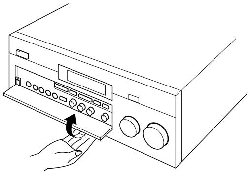
Dolby Pro Logic + 2 Digital Sound Fields
A digital sound field is created on the presence side and the rear surround side of the Dolby Pro Logic Surround-processed sound field individually. They create a wide acoustic environment and emphasize surround-effect in the room, letting you feel much presence as if you are watching a movie in a popular Dolby Stereo theater.
This combination is used on sound field programs No. 7 through No. 11, and “PROLOGIC/Enhanced” of No. 12.
natural_image
Abstract diagram with a central rectangular block and three circular elements above, enclosed in a symmetrical gray oval shape (no text or symbols)
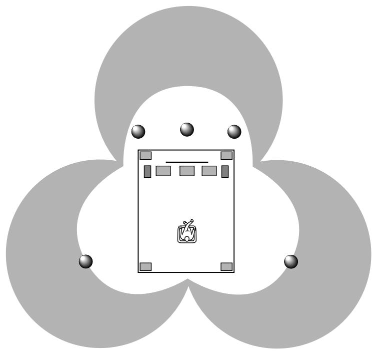
Dolby Surround AC-3 + 3 Digital Sound Fields
A digital sound field is created on the presence side and the independent left and right surround sides of the Dolby Surround AC-3-processed sound field individually. They create a wide acoustic environment and much surround effect in the room without losing high channel separation. With wide dynamic range of AC-3 sound, this sound field combination lets you feel as if you are watching a movie in the newest Dolby Stereo Digital theater. This will be the most ideal home theater sound at the present time.
This combination is available on the sound field programs No. 7 through No. 11 and “AC-3/Enhanced” of No. 12 when playing a source with the Dolby Surround AC-3 decoded.
natural_image
Abstract diagram with three overlapping circles and a central icon (no text or symbols)
Video superimpose
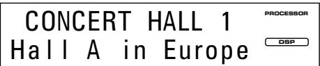
If you connect your video cassette recorder, LD player, video monitor, etc. to this unit, you can take advantage of this unit's capability to display program titles, parameter data and information for various setting changes and adjustments on your video monitor's screen. This information will be superimposed over the video image.
If there is no video source connected or it is turned off, the information will be displayed over a blue colored background.
PØ1 CONCERT HALL 1
→ Hall A in Europe
EFCT TRIM···0dB
INIT.DLY···30ms
ROOM SIZE···1.0
LIVENESS···5
S.DELAY···--ms
NOTE: The program titles, parameter data and other information are also displayed on the display panel of this unit.
text_image
CONCERT HALL 1
Hall A in Europe
PROCESSOR
DSP
SPEAKER SETUP
Setting Up Your Speaker System
This unit has been designed to provide the best sound field quality with a full seven-speaker system setup, using two extra pairs of effect speakers to generate the sound field plus one center speaker for dialog. We therefore recommend that you use a seven-speaker setup. A four-speaker system using only one pair of effect speakers for the sound field will still provide impressive ambience and effects, however, and may be a good way to begin with this unit. You can always upgrade to the full seven speaker system later. In the 4 or 5 speaker system, the Digital Sound Field Processing is still performed, but the main speakers are used for both the main channels and the front effect channels.
Use of the Center Dialog Speaker Is Recommended
When playing back a source with the “CINEMA DSP” programs No. 7 through No. 12, or when the Dolby Surround AC-3 is decoded with any DSP program used, dialog, vocals etc. are output from the center channel. Therefore, if you want to maximize the performance of your Audio/Video home theater system, it is recommended that you use a center channel speaker.
If for some reason it is not practical to use a center speaker, it is possible to enjoy movie viewing without it. Best results, however, are obtained with the full system.
Use of a Subwoofer Expands Your Sound Field
It is also possible to further expand your system with the addition of a subwoofer and amplifier. The use of a subwoofer is effective not only for reinforcing bass frequencies from any or all channels, but also for reproducing the LFE (low frequency effect) sound with high fidelity when playing back a source with the Dolby Surround AC-3 decoded. You may wish to choose the convenience of a Yamaha Active Servo Processing Subwoofer System, which has its own built-in power amp.
Four Possible Types of Speaker System Configurations Recommended
4 Speaker System
natural_image
Simple diagram of a robot with motion lines and a central device (no text or symbols)
Simplest system.
You can enjoy widely diffused sound by only adding two additional speaker units at the rear.
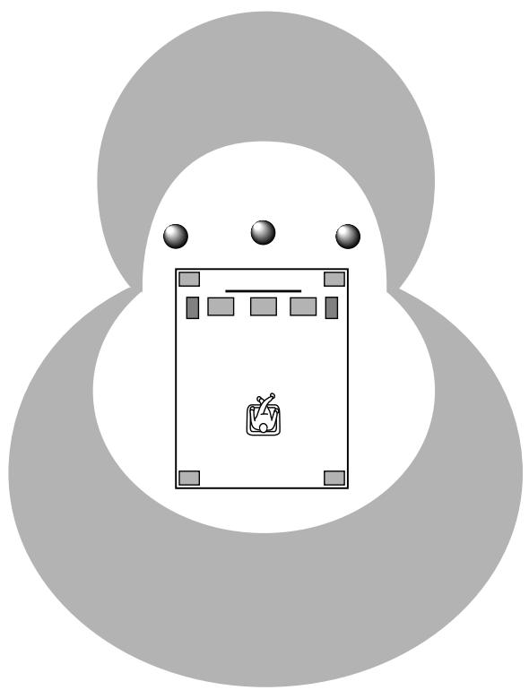
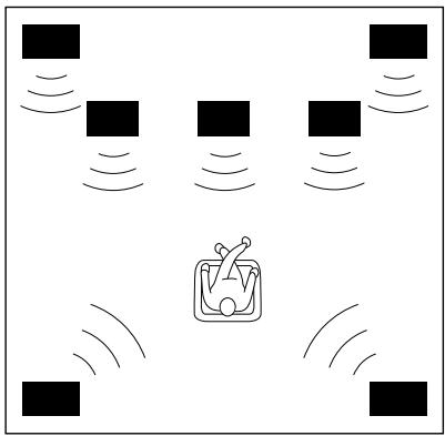
5 Speaker System
natural_image
Simple diagram of a device with four black square blocks and a central icon emitting sound waves (no text or symbols)
Good for Audio/Video sources.
By the use of center speaker, center sounds (dialog, vocals etc.) are precisely localized.
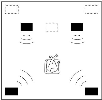
6 Speaker System
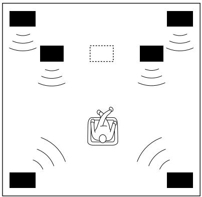
natural_image
Diagram showing a central container with a fork and surrounding square markers, surrounded by sound waves (no text or symbols)
Good for sound fields from 2-channel stereo sources.
When a normal stereo source is played back with the sound field programs No. 1 through No. 6, a sound effect matching that of a 7-speaker system can be obtained. The addition of front left and right effect speakers produces a more effective sound field.
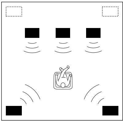
7 Speaker System
natural_image
Diagram showing four black square blocks with sound waves surrounding a central icon resembling a coffee cup or container (no text or symbols)
This is the recommended speaker system, providing the best sound effects.
When a normal stereo source is played back with the sound field programs No. 1 through No. 6, using both sets of effect speakers (front and rear), reproduces the most effective sound field. When using the sound field programs No. 7 through No. 12 or when decoding the Dolby Surround AC-3 with any program used, the center speaker provides precise center localization.
FRONT MIX switch—Set to ON.
(See page 21.)
CENTER SP—Set to PHNTM.
(See page 30.)
FRONT MIX switch—Set to ON.
(See page 21.)
CENTER SP—Set to NRML or WD.
(See page 30.)
FRONT MIX switch—Set to OFF.
(See page 21.)
CENTER SP—Set to PHNTM.
(See page 30.)
FRONT MIX switch—Set to OFF.
(See page 21.)
CENTER SP—Set to NRML or WD.
(See page 30.)
Speakers and Speaker Placement
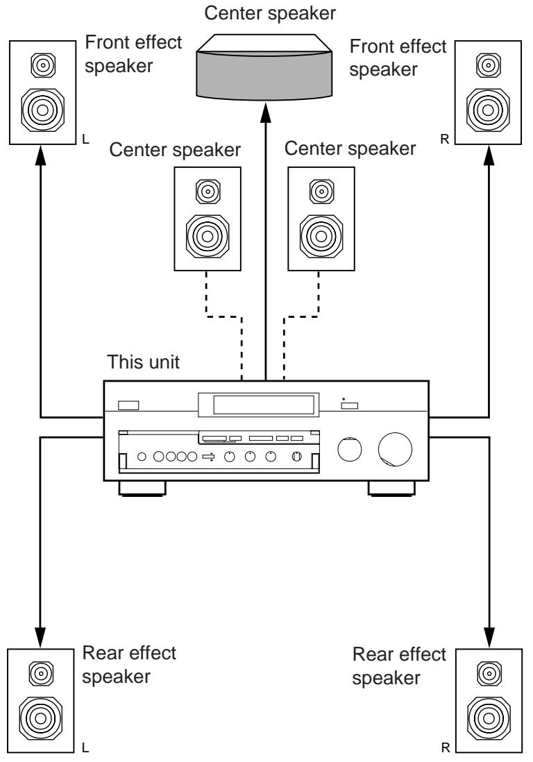
Your full seven-speaker system will require three speaker pairs: the MAIN SPEAKERS (your normal stereo speakers), the FRONT EFFECT SPEAKERS and the REAR EFFECT SPEAKERS, plus the CENTER SPEAKER. You may also be using a subwoofer.
The MAIN SPEAKERS should be high performance models and have enough power handling capacity to accept the maximum output of your audio system.
Other speakers do not have to be equal to the MAIN SPEAKERS. For precise sound localization, however, it is ideal to use high performance models that can reproduce sounds in full range for the CENTER SPEAKER and the FRONT and REAR EFFECT SPEAKERS.
Place the MAIN SPEAKERS in the normal position.
Place the FRONT EFFECT SPEAKERS further apart than the MAIN SPEAKERS, on either side of and a few feet behind and above the MAIN SPEAKER pair.
Place the REAR EFFECT SPEAKERS behind your listening position. They should be nearly six feet up from the floor.
Place the CENTER SPEAKER precisely between the two MAIN SPEAKERS. (To avoid interference, keep the speaker above or below the television monitor, or use a magnetically shielded speaker.)
If using a SUBWOOFER, such as a Yamaha Active Servo Subwoofer System, the position of the speaker is not so critical because low bass tones are not highly directional.
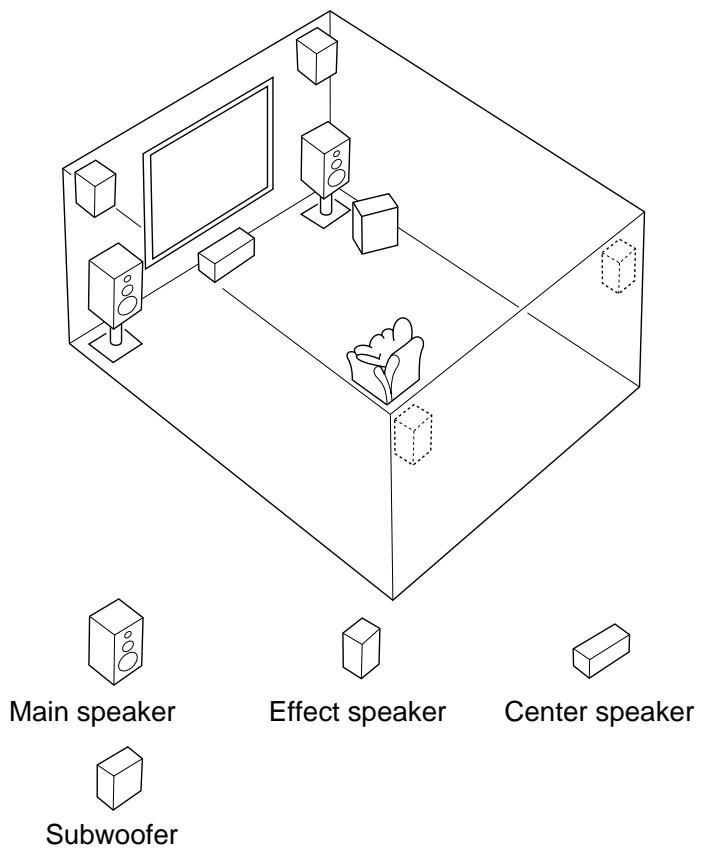
text_image
Main speaker
Effect speaker
Center speaker
Subwoofer
CONTROLS & THEIR FUNCTIONS
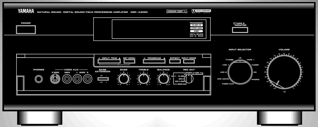
FRONT PANEL
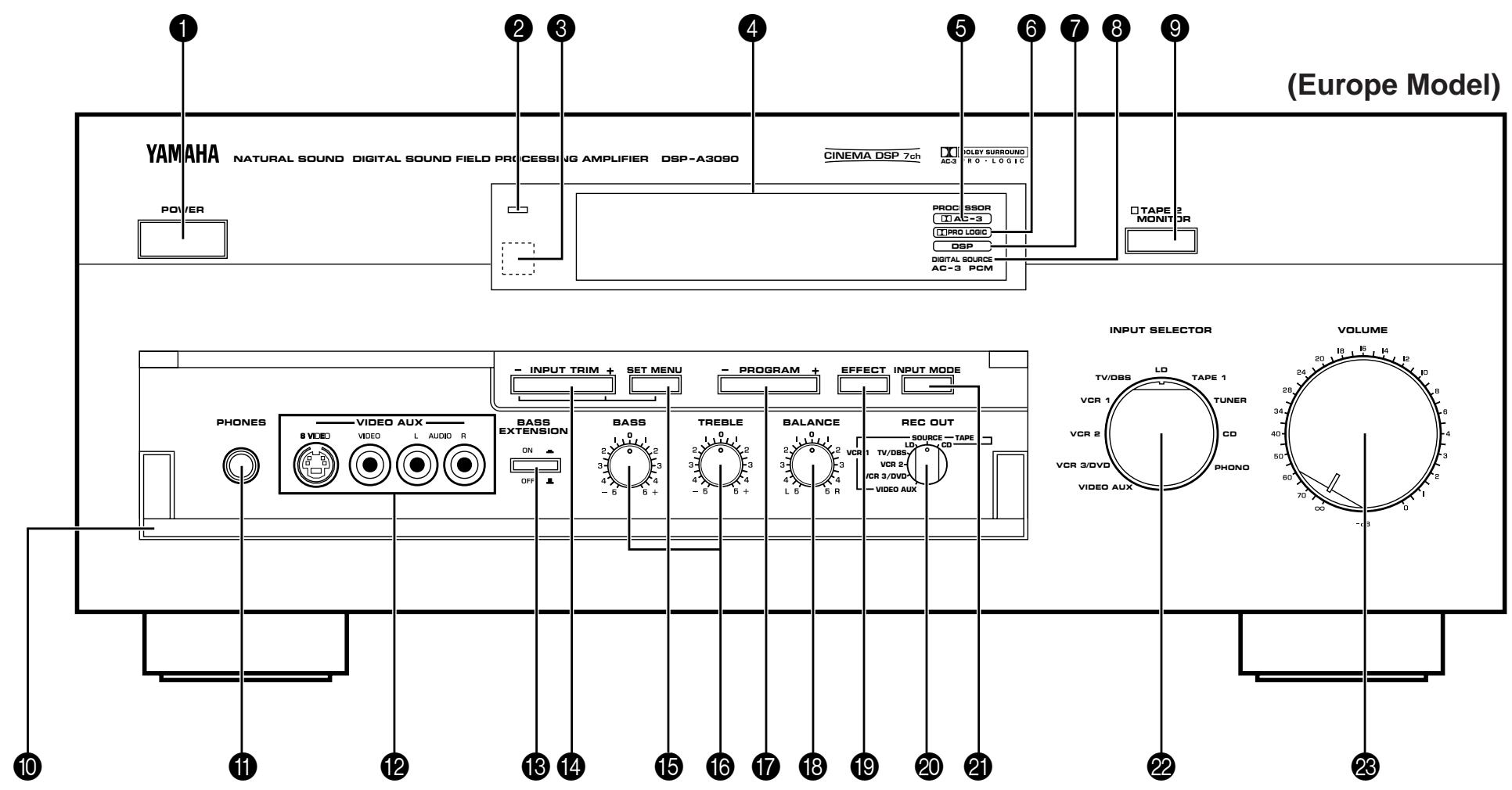
text_image
YAMAHA
NATURAL SOUND DIGITAL SOUND FIELD PROCESSING AMPLIFIER DSP-A3090
CINEMA DSP 7ch
OLBY SURROUND
AC-3
POWER
PROCESOR
TI AC-3
TI PRO LOGIC
DSP
DIGITAL SOURCE
AC-3 PCM
TAPE 2
MONITOR
(Europe Model)
PHONES
VIDEO AUX
BASS EXTENSION
INPUT TRIM +
SET MENU
PROGRAM +
EFFECT INPUT MODE
BASS
TREBLE
BALANCE
REC OUT
SOURCE - TAPE
ON
OFF
5 VCR 1
TV/DBS
VCR 2
VCR 3/DVD
VIDEO AUX
INPUT SELECTOR
VOLUME
TV/DBS
LD
TAPE 1
TUNER
CO
PHONO
24
28
34
40
50
60
70
80
90
10
11
12
13
14
15
16
17
18
19
20
21
22
23
1 POWER Switch
Turns this unit on and off.
② Standby Indicator (Europe, U.K. and Australia models only)
While the power of this unit is on, pressing the POWER key on the remote control unit switches this unit to the standby mode. In this mode, the standby indicator is half illuminated.
3 Remote Control Sensor
Signals from the remote control unit are received here.
4 Display Panel
Shows program names, parameters and information for various setting changes and adjustments.
5 AC-3 Indicator
Lights up while the built-in Dolby Surround AC-3 Decoder is functioning.
6 PRO LOGIC Indicator
Lights up while the built-in Dolby Pro Logic Surround Decoder is functioning.
7 DSP Indicator
Lights up while the built-in Digital Sound Field Processor is functioning.
8 DIGITAL SOURCE AC-3/PCM Indicator
“AC-3” lights up when a Dolby Surround AC-3 encoded signal is input to this unit. “PCM” lights up when a digital signal other than Dolby Surround AC-3 encoded signals is input to this unit.
9 TAPE 2 MONITOR Switch
Used when you have connected a second tape deck to this unit's AUDIO SIGNAL TAPE 2 jacks to select that tape as the source.
10 Control Door
See page 4 for how to open and close the control door.
11 PHONES Jack
Plug in headphones here for private listening. Sound signals from the main channels only are output here. However, if the Dolby Surround AC-3 is decoded, signals at all channels are distributed to the main channels and output here.
12 Auxiliary Input Jacks (VIDEO AUX)
Connect an auxiliary video or audio unit such as a camcorder to these jacks. If the connected video unit has a S video output terminal, connect it to the S VIDEO jack to obtain a high resolution picture. The unit connected to these jacks can be selected by the INPUT SELECTOR and REC OUT selector.
13 BASS EXTENSION Switch
When pressed inward (ON), boosts bass frequency response at the main left and right channels while maintaining overall tonal balance. If you do not have a subwoofer, the use of this switch will be effective to reinforce the bass frequencies.
* The use of this switch will not be so effective if you set the function “1. SPEAKER SET” in the SET MENU mode to output low bass signals at the main channels from the subwoofer only. (See pages 30–32 for details.)
14 INPUT TRIM Control
Adjusts the input level of each source respectively. Moreover, performs setting changes and adjustments for functions selected in the SET MENU mode.
15 SET MENU Switch
Whenever pressed, selects functions in the SET MENU mode.
16 BASS and TREBLE Controls
Adjust low and high frequency response respectively for the left main, right main and center channels only.
* Increasing low frequency response with the BASS control will not be so effective if you set the function “1. SPEAKER SET” in the SET MENU mode to output low bass signals at the main channels and/or the center channel from the subwoofer. (See pages 30–32 for details.)
17 PROGRAM Selector
Sequentially selects the digital sound field processing programs in the + or - direction.
18 BALANCE Control
Adjusts the left and right output volume to the Main Speakers to compensate for sound imbalance caused by speaker positions or listening room conditions.
19 EFFECT Switch
Normally ON, this switch can be turned OFF to disable output from the center and effect speakers so that the sound becomes normal 2-channel stereo.
* Even if this switch is off, when the Dolby Surround AC-3 is decoded, signals at all channels are distributed to the main channels and output from the main speakers.
20 RET OUT Selector
Selects the source to be recorded to a tape deck 1 or VCR 1 independently of the setting of the INPUT SELECTOR. However, when set to the SOURCE position, the setting of the INPUT SELECTOR decides the source to be recorded to a tape deck or VCR.
Switches the mode of selecting input signals between “AUTO” and “ANALOG” modes for sources that input two or more types of signals to this unit. (See page 46 for details.)
* For LD source, this switches among “AUTO”, “AC-3 RF”, “DIGITAL” and “ANALOG” modes.
Selects the input source that you want to listen to (and watch).
23 Master VOLUME Control
Simultaneously controls volume level at all outputs: front effect, main, rear effect, center, and subwoofer. (This does not affect TAPE REC OUT level.)
* When the volume is decreased by pressing the MUTING key on the remote control unit, the indicator on the master VOLUME control flashes on and off.
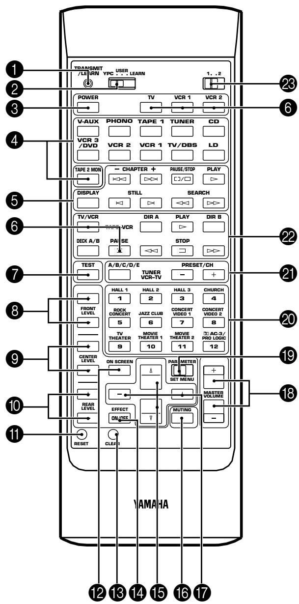
REMOTE CONTROL UNIT
text_image
TRANSMIT
/LEURN
YPC ... LEARN
USER
1..2
POWER
TV
VCR 1
VCR 2
V-AUX
PHONO
TAPE 1
TUNER
CD
VCR 3
/DVD
VCR 2
VCR 1
TV/DBS
LD
TAPE 2 MON
CHAPTER +
PAUSE/STOP
PLAY
DISPLAY
STILL
SEARCH
TV/VCR
DIR A
PLAY
DIR B
VCR
DECK A/B
PAUSE
STOP
TEST
A/B/C/D/E
TUNER
VCR-TV
PRESET/CH
FRONT
LEVEL
HALL 1
HALL 2
HALL 3
CHURCH
ROCK
CONCERT
JAZZ CLUB
CONCERT
VIDEO 1
CONCERT
VIDEO 2
5
6
7
8
TV THEATER
MOVIE THEATER 1
MOVIE THEATER 2
AC-3/
PRO LOGIC
9
10
11
12
CENTER LEVEL
ON SCREEN
PAR METER
SET MENU
+ -
REAR LEVEL
EFFECT
ON/OFF
MUTING
- -
RESET
CLEAR
12 13 14 15 16 17 YAMAHA
1 TRANSMIT/LEARN Indicator
In “LEARN” mode, lights to indicate that the key just pressed is ready for learning input. In “USER” mode, blinks when a learned key is pressed to show that a control signal has been sent to your equipment.
② YPC/USER/LEARN Switch
Set to YPC for operating this unit and Yamaha Audio/Video units. Set to USER for using learned key functions. Set to LEARN for learning new control functions. (See page 64.) ("YPC" is the abbreviation of YAMAHA Preset Code.)
③ POWER Key
Turns this unit on and off.
* (Europe, U.K. and Australia models only)
Turns the power on mode to the standby mode and vice versa.
4 Input Selector Keys
Select the input source. Pressing the key for the currently selected source will change its input mode. (See page 45 for details.)
5 CD/LD Function Keys
Operate functions on your Yamaha CD player and LD player. When the 1/2 Switch is set to 1, they operate the CD player, and when set to 2, they operate the LD player.
6 Blank Keys
Have no preset functions, so are used for learning other remote controller's functions only.
7 TEST Switch
When pressed, sends a signal to the main left, center, main right, rear right effect and rear left effect speaker in turn, and when pressed once again, sends a signal to the main and front effect speakers in turn for easy comparison of level settings.
8 FRONT LEVEL +/- Keys
Increase (+) or decrease (−) the volume level of the front effect speakers.
⑨ CENTER LEVEL +/- Keys
Increase (+) or decrease (−) the volume level of the center speaker(s).
10 REAR LEVEL +/- Keys
Increase (+) or decrease (−) the volume level of the rear effect speakers. Pressing these keys change both of the right and left effect speaker's levels at the same time with the level balance between them unchanged. To change the level balance between the right and left effect speakers, follow the instruction on page 33.
11 RESET Button
Press this button to “reset” the internal microcomputer which controls remote control operations. Microcomputer “reset” is necessary when the remote control freezes. If you have exchanged batteries in the remote control unit with new ones, press the RESET button before using the remote control unit.
* Pressing the RESET button will not erase learned functions.
12 ON SCREEN Display Key
Changes the type of display showing the program name and parameters, or information for various setting changes and adjustments on the connected monitor's screen. Whenever pressed, the screen changes to a full display, a simple display and no display in turn.
13 CLEAR Button
Used in USER or LEARN mode to erase a learned function. (See page 65.)
14 EFFECT ON/OFF Key
Normally ON, this key can be turned OFF to disable output from the center and effect speakers so that the sound becomes normal 2-channel stereo.
15 Parameter Select Keys
Select DSP program parameters, or titles of the functions in the SET MENU mode.
16 MUTING Key
Decreases the master volume level by 20 dB. While muting, the indicator on the master VOLUME control flashes on and off continuously.
17 Parameter +/- Keys
Edit DSP program parameters or used for setting changes and adjustments in the SET MENU mode.
18 MASTER VOLUME +/- Keys
Increase (+) or decrease (−) the master volume level.
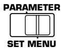
19 PARAMETER/SET MENU Switch
When set to the PARAMETER position, the Parameter Select Keys and Parameter +/- Keys will select and edit DSP program parameters. When set to the SET MENU position, the Parameter Select Keys and Parameter +/- Keys are used for setting changes and adjustments in the SET MENU mode.
20 Program Select Keys (1 through 12)
Select DSP programs 1 through 12.
21 Tuner Function Keys
Operate Yamaha tuner functions.
22 Tape Deck Function Keys
Operate Yamaha tape deck functions.
23 1/2 Switch
When the YPC/USER/LEARN Switch is set to YPC, this switches the CD/LD Function Keys to keys for use with either the CD player or LD player. ("1" for the CD player and "2" for the LD player.) When the YPC/USER/LEARN Switch is set to USER or LEARN, this switch selects the group 1 or 2 of the learnable function keys. (See page 64.)
CONNECTIONS
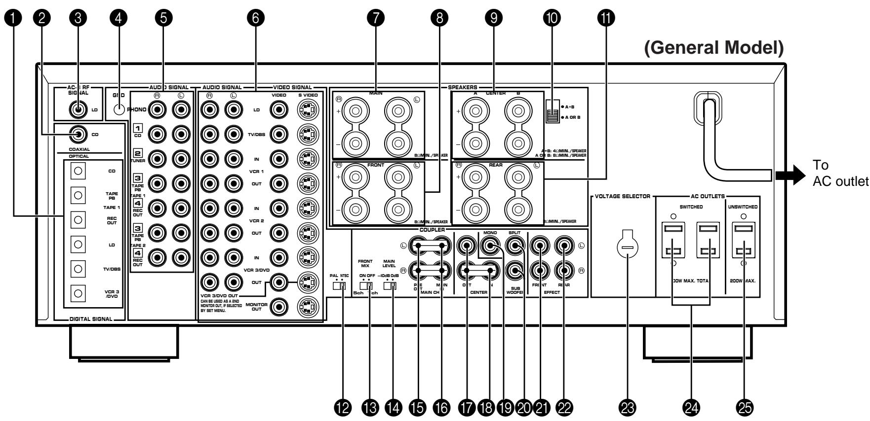
REAR PANEL PARTS AND THEIR FUNCTIONS
Before you start making connections make sure all related electronic components are turned OFF.
text_image
(General Model)
AC-1 RF
SIGNAL
LD
GND
PHONO
1
CD
COAXIAL
OPTICAL
CD
TAPE PB
TAPE 1
REC OUT
LD
TV/DBS
VCR 3 /DVD
AUDIO SIGNAL
AUDIO SIGNAL
VIDEO SIGNAL
VIDEO S VIDEO
MAIN
TV/DBS
IN
VCR 1
OUT
TAPES PAE 1
4
REC OUT
3
TAPE PB TAPE 2
4
REC OUT
VCR 3/DVD OUT +
CAN BE USED AS A DVD MONITOR OUT, P SELECTED BY SET MENU.
MONITOR OUT
SPEAKERS
A CENTER B
B:MIN./SPAKER
A OR B
A+B: 4:MIN./SPAKER
B:MIN./SPAKER
REAR
B:MIN./SPAKER
COUPLER
Palo NTSC
Sch ch
FRONT MIX MAIN LEVEL
ON OFF -IDdB QUB +
P E M IN
O T
CENTER SUB WOOFEI FRI VT RE R EFFECT
SPLIT
SUB WOOFEI
VOLTAGE SELECTOR AC OUTLETS
SWITCHED UNSWITCHED
DOW MAX. TOTA 200W MAX.
Digital Signal
To AC outlet
① OPTICAL Digital Input and Output Jacks
Can be connected with audio/video units that have optical digital signal output (and input) jacks.
② COAXIAL Digital Input Jack (for CD Player)
Can be connected with a CD player that has a coaxial digital signal output jack.
③ AC-3 RF SIGNAL Input Jack (for LD player)
Can be connected with an LD player that has an AC-3 RF audio signal output jack.
4 GND Terminal
Connects the ground wire of the turntable to produce minimum hum. In some cases, however, better results may be obtained with the ground wire disconnected.
5 AUDIO SIGNAL Connection Jacks (for Audio Source Equipment) Connect the inputs and/or outputs of your audio equipment.
6 AUDIO/VIDEO SIGNAL Connection Jacks (for Video Source Equipment)
Connect the audio and video inputs and/or outputs of your video equipment. In place of the VIDEO jacks, the S VIDEO jacks can be used for higher resolution and improved picture quality if your VCR, monitor, etc. are equipped with S-VIDEO connectors.
7 MAIN SPEAKERS Terminals
When using this unit's built-in main-channel amplifier, connect the main speakers here. The jumper bars must be plugged in to connect the MAIN IN jacks to the PRE OUT jacks.
8 FRONT SPEAKERS Terminals
When using the built-in front-channel amplifier, connect the front effect speakers here.
9 CENTER SPEAKERS Terminals
When using the built-in center-channel amplifier, connect one or two center speakers here.
10 Center Speaker Impedance Switch
Set to “A + B” when using two center speakers, or to “A OR B” when using only one center speaker.
11 REAR SPEAKERS Terminals
When using the built-in rear-channel amplifier, connect the rear effect speakers here.
12 Video NTSC/PAL Switch (General Model only)
Set this switch to the position corresponding to the standard that your video equipment employs.
13 FRONT MIX Switch
Set to “OFF (7ch)” when setting up a full 7 or 6 speaker system, or to “ON (5ch)” when setting up a 5 or 4 speaker system.
14 MAIN LEVEL Switch
Normally set to “0 dB”. If desired, you can decrease the main-channel output level at the MAIN SPEAKERS terminals by 10 dB by setting this switch to “-10 dB”.
15 PRE OUT Jacks
Main-channel line output. Connected with jumper bars to MAIN IN jacks when the built-in amplifier is used. Connected to input jacks of external stereo power amplifier (MAIN IN or TAPE PLAY jacks of integrated amplifier or receiver) when using external amplification.
16 MAIN IN Jacks
Line input to built-in main-channel amplifier. Connected with jumper bars to PRE OUT jacks when the built-in amplifier is used. Not connected when using an external power amplifier.
17 CENTER OUT Jacks
Center-channel line outputs. The CENTER OUT jack at the lower part is connected with the jumper bar to the CENTER IN jack when the built-in amplifier is used. Can be connected to input jack(s) of one or two external power amplifier(s) to drive the center speaker(s).
18 CENTER IN Jack
Line input to built-in center-channel amplifier. Connected with the jumper bar to CENTER OUT jack when the built-in amplifier is used. Not connected when using an external power amplifier.
19 MONO SUBWOOFER Jack
When using a subwoofer, connect its amplifier input to this jack. Frequencies below 90 Hz distributed from the main, center and/or rear channels are output to this jack. Signals of LFE (low frequency effect) generated when the Dolby Surround AC-3 is decoded are also output if they are assigned to this jack.
20 SPLIT SUBWOOFER Jacks
When using two subwoofers, connect their amplifiers to these jacks. Low bass signals that are output to the MONO SUBWOOFER jack are also output to these jacks. However, signals from the left main and left rear channels are output to the SPLIT L jack, and signals from the right main and right rear channels are to the SPLIT R jack separately.
21 FRONT EFFECT Out Jacks
Front-channel line output. Not connected when the built-in amplifier is used. Can be connected to input jacks of an external stereo power amplifier driving the front effect speakers.
22 REAR EFFECT Out Jacks
Rear-channel line output. Not connected when the built-in amplifier is used. Can be connected to input jacks of an external stereo power amplifier driving the rear effect speakers.
23 VOLTAGE SELECTOR (General Model only)
Be sure to set to the line voltage in your area before applying power. Consult your dealer if unsure of the correct setting.
24 SWITCHED AC OUTLETS
You may plug other audio/video units into these sockets as long as their combined power consumption does not exceed the specified value shown. “Switched” means that these components are turned on and off by this unit’s power switch.
25 UNSWITCHED AC OUTLET (U.S.A., Canada and General Models only)
The total power consumption of audio/video units plugged into this socket should not exceed the specified value shown. "Unswitched" means that power is available even when this unit is off.
NOTE: If an external power amplifier is connected to the FRONT EFFECT or REAR EFFECT output jacks, the corresponding internal amplifier will be turned off and no output will be available at the SPEAKERS terminals.
REAR PANEL SWITCH AND CONTROL SETTINGS
There are several switches and controls on the rear panel that you'll have to check before operating your system, and it's a good idea to do it before you connect cables. Locate the MAIN LEVEL slide switch (14) and FRONT MIX slide switch (13). Make sure the MAIN LEVEL switch is set to "0 dB" and the FRONT MIX switch is set to "OFF" for 7 or 6 speaker driving.
In a 5 or 4 speaker system, set the FRONT MIX switch to "ON".
Next, set the NTSC/PAL switch (12) to the position corresponding to the standard which your video equipment employs. (General Model only)
GENERAL INSTRUCTIONS FOR CONNECTIONS
Make sure that you have the left (L) and right (R) channels correctly connected. That means that jacks marked “L” on this unit must be connected to jacks marked “L” on other units. Likewise with the “R” jacks. This is easy if you remember to always use the red plug for the “R” jacks and the white plug for the “L” jacks.
For connections with audio/video source equipment, use RCA type pin plug cables with the exception described later.

natural_image
Line drawing of a bundled cable with multiple connectors (no text or symbols)
With speaker connections you must also be sure that the polarity is correct. For each amplifier and each channel, connect the plus (+) terminal of the amplifier to the plus terminal of the speaker, and connect the minus (−) terminal of the amplifier to the minus terminal of the speaker. To keep track of polarity, use a speaker cable that has one of the two wires marked by a stripe or a different color.
CONNECTING AUDIO/VIDEO SOURCE EQUIPMENT TO THIS UNIT
BASIC CONNECTIONS
* If you have YAMAHA audio/video unit numbered as 1, 2, 3, etc. on the rear panel, connections can be made easily by making sure to connect the output (or input) terminals of each unit to the same-numbered terminals of this unit.

flowchart
graph TD
    A["Turntable"] -->|OUTPUT GND| B["AC-3 RF SIGNAL"]
    C["CD player"] -->|OUTPUT| B
    D["Tuner"] -->|OUTPUT| B
    E["Tape deck 1 (DAT)"] -->|LINE OUT LINE IN| B
    F["Tape deck 2"] -->|LINE OUT LINE IN| B
    B -->|AUDIO OUT| G["VIDEO OUT"]
    B -->|AUDIO OUT| H["VIDEO OUT"]
    B -->|AUDIO OUT| I["VIDEO OUT"]
    B -->|AUDIO OUT| J["VIDEO OUT"]
    B -->|AUDIO OUT| K["VIDEO OUT"]
    B -->|AUDIO OUT| L["VIDEO OUT"]
    B -->|AUDIO OUT| M["VIDEO OUT"]
    B -->|AUDIO OUT| N["VIDEO OUT"]
    B -->|AUDIO OUT| O["VIDEO OUT"]
    B -->|AUDIO OUT| P["VIDEO OUT"]
    B -->|AUDIO OUT| Q["VIDEO OUT"]
    B -->|AUDIO OUT| R["VIDEO OUT"]
    B -->|AUDIO OUT| S["VIDEO OUT"]
    B -->|AUDIO OUT| T["VIDEO OUT"]
    B -->|AUDIO OUT| U["VIDEO OUT"]
    B -->|AUDIO OUT| V["VIDEO OUT"]
    B -->|AUDIO OUT| W["VIDEO OUT"]
    B -->|AUDIO OUT| X["VIDEO OUT"]
    B -->|AUDIO OUT| Y["VIDEO OUT"]
    B -->|AUDIO OUT| Z["VIDEO OUT"]
    B -->|AUDIO OUT| AA["VIDEO OUT"]
    B -->|AUDIO OUT| AB["VIDEO OUT"]
    B -->|AUDIO OUT| AC["VIDEO OUT"]
    B -->|AUDIO OUT| AD["VIDEO OUT"]
    B -->|AUDIO OUT| AE["VIDEO OUT"]
    B -->|AUDIO OUT| AF["VIDEO OUT"]
    B -->|AUDIO OUT| AG["VIDEO OUT"]
    B -->|AUDIO OUT| AH["VIDEO OUT"]
    B -->|AUDIO OUT| AI["VIDEO OUT"]
    B -->|AUDIO OUT| AJ["VIDEO OUT"]
    B -->|AUDIO OUT| AK["VIDEO OUT"]
    B -->|AUDIO OUT| AL["VIDEO OUT"]
    B -->|AUDIO OUT| AM["VIDEO OUT"]
    B -->|AUDIO OUT| AN["VIDEO OUT"]
    B -->|AUDIO OUT| AO["VIDEO OUT"]
    B -->|AUDIO OUT| AP["VIDEO OUT"]
    B -->|AUDIO OUT| AQ["VIDEO OUT"]
    B -->|AUDIO OUT| AR["VIDEO OUT"]
    B -->|AUDIO OUT| AS["VIDEO OUT"]
    B -->|AUDIO OUT| AT["VIDEO OUT"]
    B -->|AUDIO OUT| AU["VIDEO OUT"]
    B -->|AUDIO OUT| AV["VIDEO OUT"]
    B -->|AUDIO OUT| AW["VIDEO OUT"]
    B -->|AUDIO OUT| AX["VIDEO OUT"]
    B -->|AUDIO OUT| AY["VIDEO OUT"]
    B -->|AUDIO OUT| AZ["VIDEO OUT"]
    B -->|AUDIO OUT| BA["VIDEO OUT"]
    B -->|AUDIO OUT| BB["VIDEO OUT"]
    B -->|AUDIO OUT| BC["VIDEO OUT"]
    B -->|AUDIO OUT| BD["VIDEO OUT"]
    B -->|AUDIO OUT| BE["VIDEO OUT"]
    B -->|AUDIO OUT| BF["VIDEO OUT"]
    B -->|AUDIO OUT| BG["VIDEO OUT"]
    B -->|AUDIO OUT| BH["VIDEO OUT"]
    B -->|AUDIO OUT| BI["VIDEO OUT"]
    B -->|AUDIO OUT| BJ["VIDEO OUT"]
    B -->|AUDIO OUT| BK["VIDEO OUT"]
If you wish to connect a second monitor TV (or a projector) to this unit, you can switch the VCR 3/DVD VIDEO OUT jack (and S VIDEO jack also) to a second monitor out jack for the connection with another monitor TV. (See page 43.)
* For shaded parts, see pages 23 to 25.
CONNECTING TO DIGITAL (OPTICAL AND COAXIAL) JACKS
If your CD player, video cassette recoder, LD player, etc. are equipped with optical digital audio signal output (and input) jacks, they can be connected to this unit's OPTICAL digital signal input (and output) jacks.
To make a connection between optical digital audio signal jacks, remove the cover from each jack, and then connect them by using a commercially available optical fiber cable that conforms to EIAJ standards. Other cables might not function correctly.
Additionally, this unit is equipped with a COAXIAL type of digital audio signal input jack for the connection with the CD player only, so you can select either the OPTICAL or the COAXIAL jack for a digital connection with the CD player.
Even if you connect an audio/video unit to the OPTICAL (or COAXIAL) jack of this unit, you must keep the unit connected with the same named analog audio signal jacks of this unit, because digital signal cannot be recorded by a tape deck or VCR other than the tape deck connected to the OPTICAL TAPE 1 REC OUT jack of this unit. You can switch the selection of input signals between “digital” and “analog” easily. (See page 46 for details.)
NOTE: When connecting an audio/video unit to both of the digital and analog jacks of this unit, make sure to connect to both jacks of the same name.
NOTE: Be sure to attach the covers when the OPTICAL jacks are not being used, in order to protect the jacks from dust.
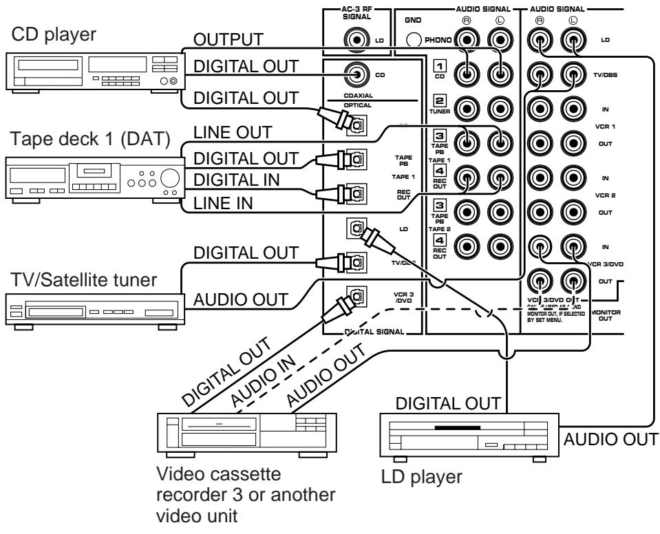
text_image
CD player
OUTPUT
DIGITAL OUT
DIGITAL OUT
LINE OUT
DIGITAL OUT
DIGITAL IN
LINE IN
Tape deck 1 (DAT)
TV/Satellite tuner
DIGITAL OUT
AUDIO OUT
DIGITAL OUT
AUDIO IN
AUDIO OUT
Video cassette recorder 3 or another video unit
AC-3 RF SIGNAL
GND
PHOND
AUDIO SIGNAL
AUDIO SIGNAL
LD
1
CD
2
TUNER
3
TAPE PB
TAPE 1
4
REC OUT
3
TAPE PB
TAPE 2
4
REC OUT
VCR 3 /DVD
Digital Signal
TV/OBS
IN
VCR 1
OUT
IN
VCR 2
OUT
IN
VCR 3/DVD
OUT
MONITOR OUT
AUDIO OUT
LD player
NOTE: All digital audio signal input jacks are applicable to the sampling frequency of 32 kHz, 44.1 kHz and 48 kHz.
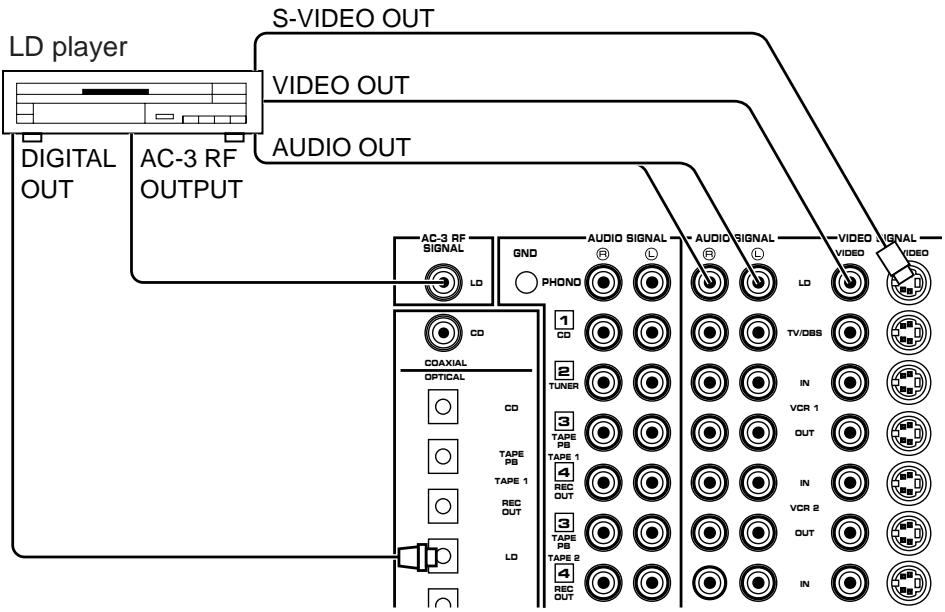
CONNECTING TO AC-3 RF OUTPUT OF THE LD PLAYER
If your LD player has an AC-3 RF signal output jack, connect it to this unit's AC-3 RF SIGNAL input jack. Audio signals encoded with the Dolby Surround AC-3 are input to this unit by this connection.
* To play back an LD source decoding its AC-3 RF signal, set the input mode of LD player to “AUTO” or “AC-3 RF”. (See page 46 for details.)
It is also necessary to connect the LD player to this unit's OPTICAL digital audio signal input jack and/or analog audio signal input jacks regardless of the AC-3 RF signal connection, for playing back an LD source with the Dolby Pro Logic Surround decoded or in normal stereo (or monaural).
NOTE: AC-3 RF audio input signal cannot be recorded by a tape deck or VCR. To record an LD source, the LD player must be connected to the OPTICAL digital audio signal input jack and/or analog audio signal input jacks of this unit.
flowchart
graph TD
    A["LD player"] --> B["S-VIDEO OUT"]
    A --> C["VIDEO OUT"]
    A --> D["AUDIO OUT"]
    E["DIGITAL OUT"] --> F["AC-3 RF OUTPUT"]
    G["AC-3 RF SIGNAL"] --> H["LD"]
    I["GND"] --> J["PHONO"]
    K["AUDIO SIGNAL"] --> L["LD"]
    M["VIDEO SIGNAL"] --> N["TV/DBS"]
    O["COAXIAL"] --> P["CD"]
    Q["TAPE PB"] --> R["OPTICAL"]
    S["TAPE 1"] --> T["CD"]
    U["REC OUT"] --> V["LD"]
    W["TAPE PB"] --> X["TOPE"]
    Y["TAPE 2"] --> Z["TOPE"]
    AA["RECO OUT"] --> AB["LD"]
    AC["IN"] --> AD["VCR 1"]
    AE["VCR 2"] --> AF["VCR 1"]
    AG["VCR 2"] --> AH["VCR 1"]
    AI["VCR 2"] --> AJ["VCR 1"]
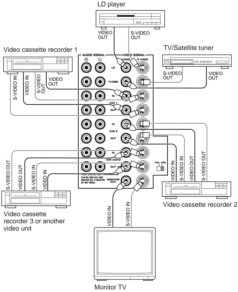
CONNECTING TO S VIDEO JACKS
If your video cassette recorder, LD player, etc. and your monitor are equipped with “S” (high-resolution) video terminals, connect them to this unit’s S VIDEO jacks, and connect this unit’s
S VIDEO MONITOR OUT jack to the “S” video input of your monitor. Otherwise, connect the composite video jacks from your video cassette recorder, LD player, etc. to the VIDEO jacks of this unit, and connect this unit’s VIDEO MONITOR OUT jack to the composite video input of your monitor.
NOTE: If video signals are sent to both S VIDEO input and VIDEO input jacks, the signals will be sent to their respective output jacks independently.
NOTE: If your unit is the General Model, be sure the NTSC/PAL switch has been correctly set to the standard that your video equipment employs. U.S.A. and Canada models have no switch and use the NTSC standard, while other models without a switch use the PAL standard.
Notes about the Video superimpose
- If you watch a video source that is connected to both S VIDEO and VIDEO input jacks of this unit, signals of screen display information are output from only the S VIDEO MONITOR OUT jack.
- When no video signal is input to either S VIDEO or VIDEO input jacks of this unit, signals of screen display information are output from both S VIDEO MONITOR OUT and VIDEO MONITOR OUT jacks with a color background.
* For the General Model, if the NTSC/PAL switch on the rear panel is set to “PAL”, nothing will be output from either S VIDEO MONITOR OUT or VIDEO MONITOR OUT jack in this case.
flowchart
graph TD
    A["LD player"] -->|VIDEO OUT| B["TV/Satellite tuner"]
    A -->|S-VIDEO OUT| B
    C["Video cassette recorder 1"] -->|S-VIDEO IN| D["Monitor TV"]
    C -->|VIDEO OUT| D
    E["Video cassette recorder 2"] -->|S-VIDEO IN| D
    E -->|VIDEO OUT| D
    F["Video cassette recorder 3 or another video unit"] -->|S-VIDEO IN| D
    F -->|VIDEO OUT| D
    G["Monitor TV"] -->|S-VIDEO IN| D
    H["Audio SIGNAL"] --> I["LD"]
    H --> J["IN"]
    H --> K["VCR 1"]
    H --> L["VCR 2"]
    H --> M["VCR 3/DVD"]
    H --> N["MONITOR OUT"]
    H --> O["PAL NTSC"]
    H --> P["S-VIDEO OUT"]
    H --> Q["S-VIDEO OUT"]
    style A fill:#f9f,stroke:#333
    style C fill:#ccf,stroke:#333
    style E fill:#cfc,stroke:#333
    style F fill:#fcc,stroke:#333
    style G fill:#ffc,stroke:#333
    style H fill:#fcc,stroke:#333
Make a connection as figured below with a commercially available scart-plug connector cable.
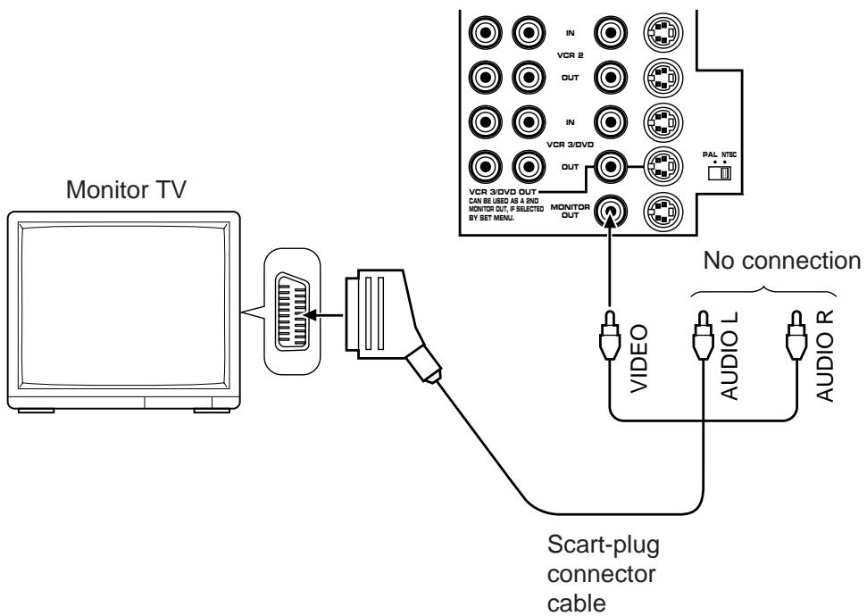
flowchart
graph TD
    A["Monitor TV"] --> B["Scart-plug connector cable"]
    B --> C["Video"]
    B --> D["AUDIO L"]
    B --> E["AUDIO R"]
    C --> F["Monitor OUT"]
    D --> G["VCR 3/DVD OUT CAN BE USED AS A AND MONITOR OUT, IF SELECTED BY SET MENU."]
    E --> H["VCR 2 OUT"]
    F --> I["VCR 3/DVD OUT"]
    G --> J["VCR 3/DVD OUT"]
    H --> K["VCR 3/DVD OUT"]
    I --> L["VCR 3/DVD OUT"]
    J --> M["VCR 3/DVD OUT"]
    K --> N["VCR 3/DVD OUT"]
    L --> O["VCR 3/DVD OUT"]
    M --> P["VCR 3/DVD OUT"]
    N --> Q["VCR 3/DVD OUT"]
    O --> R["VCR 3/DVD OUT"]
    P --> S["VCR 3/DVD OUT"]
CONNECTING SPEAKER SYSTEMS
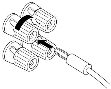
Connect the SPEAKERS terminals to your speakers with wire of the proper gauge, cut as short as possible. If the connections are faulty, no sound will be heard from the speakers. Make sure that the polarity of the speaker wires is correct, that is, + and – markings are observed. If these wires are reversed, the sound will be unnatural and will lack bass. Do not let the bare speaker wires touch each other or any other metal part as this could damage this unit and/or speakers.
NOTE: Use speakers with the specified impedance shown on the rear of this unit.

text_image
Diagram showing a tool interacting with three cylindrical components labeled 1, 2, and 3, with arrows indicating movement or assembly.
Red: positive (+)
Black: negative (−)
① Unscrew the knob.
② Insert the bare wire.
[Remove approx. 5mm (1/4") insulation from the speaker wires.]
③ Tighten the knob and secure the wire.
NOTE: Banana Plug connections are also possible (U.S.A., Canada, Australia and General models only). Simply insert the Banana Plug connector into the corresponding terminal.
natural_image
Diagram of three cylindrical connectors connected to a cable, showing internal structure and wiring (no text or symbols)
CONNECTING THE MAIN SPEAKERS TO THIS UNIT
Connect the MAIN speakers to the MAIN SPEAKERS terminals of this unit. Make sure that the jumper bars between the PRE OUT and MAIN IN jacks on the rear panel are in place. It is also possible to use an external power amplifier if more power is desired. In this case, remove the jumper bars and connect the PRE OUT jacks to the INPUT jacks of a stereo power amplifier with a stereo pin cable—making sure to connect the left and right channels correctly. Connect the MAIN speakers to the speaker output terminals of the power amplifier.
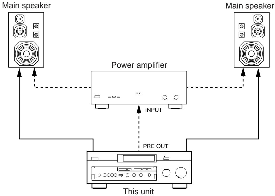
flowchart
graph TD
    A["Main speaker"] --> B["Power amplifier"]
    C["Main speaker"] --> B
    B --> D["This unit"]
    D --> E["PRE OUT"]
    E --> B
    B --> F["INPUT"]
CONNECTING THE EFFECT SPEAKERS AND THE CENTER SPEAKER(S) TO THIS UNIT
Connect the FRONT effect speakers to the FRONT SPEAKERS terminals of this unit.
If the FRONT effect speakers are not used, the FRONT MIX switch should be set to "ON".
Connect the REAR effect speakers to the REAR SPEAKERS terminals of this unit.
Connect the CENTER speaker to the CENTER SPEAKERS terminals. If you will be using one CENTER speaker, connect it to either the A or B terminals and set the CENTER speaker impedance switch to “A OR B” (bottom position). If using two CENTER speakers, connect them to the A and B terminals, and set the switch to “A + B” (top position). If, however, you will not be using a CENTER speaker, be sure to set the CENTER SP mode to “PHNTM” (phantom). (See page 30.)
NOTE: The speaker connections above are fine for most applications. If for some reason, however, you wish to use an external power amp for any or all of the effect and center channels, connect the line level output jack(s) for each channel to the INPUT jacks of the external amp and connect the corresponding speaker pair to the speaker terminals of the external amp.
NOTE: If the pin plug is inserted in the FRONT/REAR EFFECT jacks, the speaker output from the built-in amplifier will be cut off.
flowchart
graph TD
    A["Speaker L"] --> B["Central Unit"]
    C["Speaker R"] --> B
    D["Speaker L"] --> B
    E["Speaker R"] --> B
    F["Speaker L"] --> B
    G["Speaker R"] --> B
    H["Speaker L"] --> B
    I["Speaker R"] --> B
    J["Speaker L"] --> B
    K["Speaker R"] --> B
    L["Speaker L"] --> B
    M["Speaker R"] --> B
    N["Speaker L"] --> B
    O["Speaker R"] --> B
    P["Speaker L"] --> B
    Q["Speaker R"] --> B
    R["Speaker L"] --> B
    S["Speaker R"] --> B
    T["Speaker L"] --> B
    U["Speaker R"] --> B
    V["Speaker L"] --> B
    W["Speaker R"] --> B
    X["Speaker L"] --> B
    Y["Speaker R"] --> B
    Z["Speaker L"] --> B
    AA["Speaker R"] --> B
    AB["Speaker L"] --> B
    AC["Speaker R"] --> B
    AD["Speaker L"] --> B
    AE["Speaker R"] --> B
    AF["Speaker L"] --> B
    AG["Speaker R"] --> B
    AH["Speaker L"] --> B
    AI["Speaker R"] --> B
    AJ["Speaker L"] --> B
    AK["Speaker R"] --> B
    AL["Speaker L"] --> B
    AM["Speaker R"] --> B
    AN["Speaker L"] --> B
    AO["Speaker R"] --> B
    AP["Speaker L"] --> B
    AQ["Speaker R"] --> B
    AR["Speaker L"] --> B
    AS["Speaker R"] --> B
    AT["Speaker L"] --> B
    AU["Speaker R"] --> B
    AV["Speaker L"] --> B
    AW["Speaker R"] --> B
    AX["Speaker L"] --> B
    AY["Front effect speaker"]
    AZ["Center speaker"]
    BA["Front effect speaker"]
    BB["Center speaker"]
    BC["Center speaker"]
    BD["Center speaker"]
    BE["Center speaker"]
    BF["Center speaker"]
    BG["Center speaker"]
    BH["Center speaker"]
    BI["Center speaker"]
    BJ["Center speaker"]
    BK["Center speaker"]
    BL["Center speaker"]
    BM["Center speaker"]
    BN["Center speaker"]
    BO["Center speaker"]
    BP["Center speaker"]
    BPB["Center speaker"]
    BPC["Center speaker"]
    BPD["Center speaker"]
    BPE["Center speaker"]
    BPF["Center speaker"]
    BPG["Center speaker"]
    BPH["Center speaker"]
    BPI["Center speaker"]
    BPJ["Center speaker"]
    BPK["Center speaker"]
    BPL["Center speaker"]
    BPM["Center speaker"]
    BPN["Center speaker"]
    BPO["Center speaker"]
    BPP["Center speaker"]
    BPQ["Center speaker"]
    BP_R["Center speaker"]
    BP_S["Center speaker"]
    BP_T["Center speaker"]
    BP_U["Center speaker"]
    BP_V["Center speaker"]
    BP_W["Center speaker"]
    BP_X["Center speaker"]
    BP_Y["Center speaker"]
    BP_Z["Center speaker"]
ADDING A SUBWOOFER
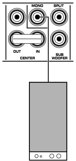
You may wish to add a subwoofer to reinforce the bass frequencies.
This unit provides line-level subwoofer outputs. If you use one subwoofer, connect the MONO SUBWOOFER jack to the INPUT jack of the subwoofer amplifier, and connect the speaker terminals of the subwoofer amplifier to the subwoofer.
text_image
MONO
SPLIT
OUT
IN
CENTER
SUB
WOOFER
Subwoofer system
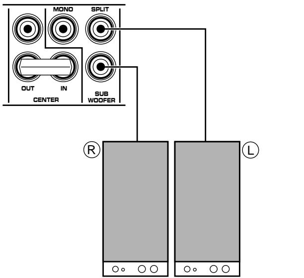
If you wish to obtain more presence in your listening room, the use of two subwoofers is recommended. To connect two subwoofers to this unit, connect the “left” SPLIT SUBWOOFER jack to the INPUT jack of the amplifier driving the left subwoofer, and the “right” SPLIT SUBWOOFER jack to the INPUT jack of the amplifier driving the right subwoofer, and then connect each subwoofer to the corresponding amplifier.
text_image
MOND
SPLIT
OUT
IN
SUB
WOOFER
CENTER
R
L
Subwoofer system
Subwoofer system
With some subwoofers, including the Yamaha Active Servo Processing Subwoofer System, the amplifier and subwoofer are in the same unit.
SELECTING THE OUTPUT MODES SUITABLE FOR YOUR SPEAKER SYSTEM
This unit provides you the following four functions to determine the method of distributing output signals to speakers suitable for your audio system. When speaker connections are all completed, select a proper position on each function to make the best use of your speaker system.
1. SPEAKER SET
1A. CENTER SPEAKER(S)
1B. REAR SPEAKERS *
1C. MAIN SPEAKERS *
1D. LFE/BASS OUT *
Note
Functions with “*” are provided only for better sound reproduction with the Dolby Surround AC-3 decoding.
DESCRIPTION OF EACH FUNCTION
1A. CENTER SPEAKER(S)
Choices: NRML/WD/PHNTM
Preset position: NRML
NRML: Select this position when you use a center speaker that is smaller than the main speakers. In this position, low bass signals (below 90 Hz) at the center channel are output from the main speakers (or the SUBWOOFER jacks if the SW or BOTH position is selected on “1D. LFE/BASS OUT”).
WD: Select this position when your center speaker is approximately the same size as the main speakers.
PHNTM (Phantom):
Select this position when you do not have a center speaker. The center channel sound will be output from the left and right main speakers.
1B. REAR SPEAKERS
Choices: SMALL/LARGE
Preset position: SMALL
SMALL:
Select this position if your rear effect speakers do not have a high ability for bass reproduction.
In this position, low bass signals (below 90 Hz) at the rear surround channels are output from the main speakers (or the SUBWOOFER jacks if the SW or BOTH position is selected on “1D. LFE/BASS OUT”).
LARGE:
Select this position if your rear effect speakers have a high ability for bass reproduction, or a subwoofer is connected to the rear effect speaker in parallel.
In this position, full range signals are output from the rear effect speakers.
1C. MAIN SPEAKERS
Choices: SMALL/LARGE
Preset position: LARGE
SMALL:
Select this position if your main speakers do not have a high ability for bass reproduction. However, if your system does not include a subwoofer, do not select this position. In this position, low bass signals (below 90 Hz) at the main channels are output from the SUBWOOFER jacks (if the SW or BOTH position is selected on “1D. LFE/BASS OUT”).
LARGE:
Select this position if your main speakers have a high ability for bass reproduction.
In this position, full range signals present at the main channels are output from the main speakers.
1D. LFE/BASS OUT
Choices: MAIN/SW/BOTH
Preset position: SW
MAIN: Select this position if your system does not include a subwoofer.
In this position, full range signals present at the main channels, signals from the LFE channel and other low bass signals that are selected on 1A to 1C to be distributed from other channels are output from the main speakers.
SW/BOTH:
Select either the SW or BOTH position if your system includes a subwoofer.
In either position, signals at LFE channel and other low bass signals that are selected on 1A to 1C to be distributed from other channels are output from the SUBWOOFER jacks.
When the LARGE position is selected on “1C. MAIN SPEAKERS”, in the SW position, no signal is distributed from the main channels to the SUBWOOFER jacks, however in the BOTH position, low bass signals from the main channels are output to both of the main speakers and the SUBWOOFER jacks.
METHOD OF CHANGING SELECTIONS
The use of the remote control unit is recommended for simple operation. Operations should be made watching information on this unit's display panel or the monitor screen.
- Turn the power of this unit on. (If you want to display information on the monitor, turn the power of the monitor on.)
Front panel
or
Remote control

- Set the PARAMETER/SET MENU switch to the SET MENU position on the remote control unit.
Remote control
- Press ▽ once so that “1. SPEAKER SET” lights up on the display.
Remote control
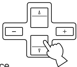
flowchart
graph TD
    A["Δ"] --> B["−"]
    A --> C["+"]
    B --> D["▽"]
    C --> D
    D --> E["ce"]
- Press “+” or “−” once.
Remote control
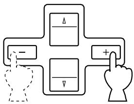
flowchart
graph TD
    A["Δ"] --> B["-"]
    C["Δ"] --> D["-"]
    E["Δ"] --> F["+"]
    G["Δ"] --> H["+"]
    I["Δ"] --> J["+"]
    K["Δ"] --> L["+"]
    M["Δ"] --> N["+"]
    O["Δ"] --> P["+"]
    Q["Δ"] --> R["+"]
    S["Δ"] --> T["+"]
    U["Δ"] --> V["+"]
    W["Δ"] --> X["+"]
    Y["Δ"] --> Z["+"]
    AA["Δ"] --> AB["+"]
    AC["Δ"] --> AD["+"]
    AE["Δ"] --> AF["+"]
    AG["Δ"] --> AH["+"]
    AI["Δ"] --> AJ["+"]
    AK["Δ"] --> AL["+"]
    AM["Δ"] --> AN["+"]
    AO["Δ"] --> AP["+"]
    AQ["Δ"] --> AR["+"]
    AS["Δ"] --> AT["+"]
    AU["Δ"] --> AV["+"]
    AW["Δ"] --> AX["+"]
    AY["Δ"] --> AZ["+"]
    BA["Δ"] --> BB["+"]
    BC["Δ"] --> BD["+"]
    BE["Δ"] --> BF["+"]
    BG["Δ"] --> BH["+"]
    BI["Δ"] --> BJ["+"]
    BK["Δ"] --> BL["+"]
    BM["Δ"] --> BN["+"]
    BO["Δ"] --> BP["+"]
    BQ["Δ"] --> BR["+"]
    BS["Δ"] --> BT["+"]
    BU["Δ"] --> BV["+"]
    BW["Δ"] --> BX["+"]
    BY["Δ"] --> BZ["+"]
- Press (or ) once or more until the title of function on which you will change the selection appears on the display.
Remote control
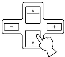
flowchart
graph TD
    A["Δ"] --> B["−"]
    A --> C["+"]
    D["▽"] --> E["↓"]
- Press "+" or "-" once or more so that the arrow points the position you will select. Remote control
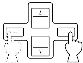
flowchart
graph TD
    A["Δ"] --> B["+"]
    C["-"] --> B
    D["▽"] --> B
    B --> E["Hand Icon"]
- Repeat step 5 and 6 to change selections on other functions in the same way.
NOTE: The same operations can also be made on the front panel. First press the SET MENU switch and then INPUT TRIM control. Select the title of function by pressing the SET MENU switch, and change the choice by pressing the INPUT TRIM control.
MAIN/CENTER/EFFECT SPEAKER LEVEL BALANCE ADJUSTMENT
This operation uses an internal test-tone generator for balancing the levels of the main, center and effect speakers.
- Depress the TEST switch on the remote control so that “TEST DOLBY SUR.” appears on the display panel to enter test mode. A hiss-like calibration signal should be heard from the left main speaker, center speaker(s), right main speaker, right rear effect speaker and left rear effect speaker in turn (see diagram). Adjust the master VOLUME to a normal listening level.
* The state of test-tone output is shown by the display panel and the monitor screen. (On the monitor screen, it is shown by an image of audio listening room.) This is convenient for adjusting each speaker level.
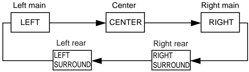
flowchart
graph LR
    A["LEFT"] --> B["CENTER"]
    B --> C["RIGHT"]
    D["LEFT SURROUND"] --> E["RIGHT SURROUND"]
    style A fill:#f9f,stroke:#333
    style B fill:#ccf,stroke:#333
    style C fill:#cfc,stroke:#333
    style D fill:#fcc,stroke:#333
    style E fill:#cff,stroke:#333
- Adjust the center and rear level by using the CENTER and REAR LEVEL +/- keys on the remote control so that the sound coming from the corresponding speaker seems to be at the same level as that from the main speakers when you are at a normal listening position. The REAR LEVEL +/- keys adjust the right rear level if pressed while the test-tone is output from the right rear effect speaker, and adjust the left rear level if pressed while the test-tone is output from the left rear effect speaker. If the REAR LEVEL + or - key is pressed while the test-tone is output from other than the right or left rear effect speaker, the key adjusts either the right or left rear level that has been adjusted last time.
* If there is insufficient volume from the effect speakers, you may decrease the main speaker volume level by setting the MAIN LEVEL switch on the rear panel to “-10 dB”, and adjust the center and rear level again. Volume controls on external power amplifiers may also be adjusted if necessary to achieve proper balance.
* Pressing the Parameter + or – key (only when the PARAMETER/SET MENU switch is set to the PARAMETER position) transfers the test-tone from the speaker that is currently outputting the test-tone to the right or left rear effect speaker. Pressing “+” transfers the test-tone to the right rear effect speaker, and “−” to the left rear effect speaker.
* Pressing and holding the Parameter Select ▽ or △ key (only when the PARAMETER/SET MENU switch is set to the PARAMETER position) fixes the test-tone on the speaker that is currently outputting the test-tone.
NOTE: If not using a center speaker, be sure to set the CENTER SP mode to the PHNTM (phantom) position. You will then hear the center channel test tone from the left and right main speakers.