MODE D'EMPLOI X7 PIAGGIO
SERVICE STATION MANUAL
XXXXXX
X7 250ie
X7 250ie
The descriptions and illustrations given in this publication are not binding. While the basic specifications as described and illustrated in this manual remain unchanged, PIAGGIO-GILERA reserves the right, at any time and without being required to update this publication beforehand, to make any changes to components, parts or accessories, which it considers necessary to improve the product or which are required for manufacturing or construction reasons.
Not all versions shown in this publication are available in all Countries. The availability of single versions should be checked at the official Piaggio sales network.
Copyright 2007 - PIAGGIO & C. S.p.A. Pontedera. All rights reserved. Reproduction of this publication in whole or in part is prohibited."
PIAGGIO & C. S.p.A. - After-Sales
V.Le Rinaldo Piaggio, 23 - 56025 PONTEDERA (Pi)
SERVICE STATION MANUAL X7 250ie
This service station manual has been drawn up by Piaggio & C. Spa to be used by the workshops of Piaggio-Gilera dealers. It is assumed that the user of this manual for maintaining and repairing Piaggio vehicles has a basic knowledge of mechanical principles and vehicle repair technique procedures. Any significant changes to vehicle characteristics or to specific repair operations will be communicated by updates to this manual. Nevertheless, no mounting work can be satisfactory if the necessary equipment and tools are unavailable. It is therefore advisable to read the sections of this manual concerning special tools, along with the special tool catalogue.
N.B. Provides key information to make the procedure easier to understand and carry out.
CAUTION Refers to specific procedures to carry out for preventing damages to the vehicle.
WARNING Refers to specific procedures to carry out to prevent injuries to the repairer.

Personal safety Failure to completely observe these instructions will result in serious risk of personal injury.

Safeguarding the environment Sections marked with this symbol indicate the correct use of the vehicle to prevent damaging the environment.

Vehicle intactness The incomplete or non-observance of these regulations leads to the risk of serious damage to the vehicle and sometimes even the invalidity of the guarantee.
INDEX OF TOPICS
CHARACTERISTICS
CHAR
TOOLING
TOOL
MAINTENANCE
MAIN
TROUBLESHOOTING
TROUBL
ELECTRICAL SYSTEM
ELESYS
ENGINE FROM VEHICLE
ENGVE
ENGINE
ENG
INJECTION
INJEC
SUSPENSIONS
SUSP
BRAKING SYSTEM
BRAK SYS
COOLING SYSTEM
COOL SYS
CHASSIS
CHAS
PRE-DELIVERY
PRE DE
TIME
TIME
INDEX OF TOPICS
CHARACTERISTICS
CHAR
This section describes the general specifications of the vehicle.
Rules
This section describes general safety rules for any maintenance operations performed on the vehicle.
Safety rules
- If work can only be done on the vehicle with the engine running, make sure that the premises are wellventilated, using special extractors if necessary; never let the engine run in an enclosed area. Exhaust fumes are toxic.
- The battery electrolyte contains sulphuric acid. Protect your eyes, clothes and skin. Sulphuric acid is highly corrosive; in the event of contact with your eyes or skin, rinse thoroughly with abundant water and seek immediate medical attention.
- The battery produces hydrogen, a gas that can be highly explosive. Do not smoke and avoid sparks or flames near the battery, especially when charging it.
- Fuel is highly flammable and it can be explosive given some conditions. Do not smoke in the working area, and avoid open flames or sparks.
- Clean the brake pads in a well-ventilated area, directing the jet of compressed air in such a way that you do not breathe in the dust produced by the wear of the friction material. Even though the latter contains no asbestos, inhaling dust is harmful.
Maintenance rules
- Use original PIAGGIO spare parts and lubricants recommended by the Manufacturer. Non-original or non-conforming spares may damage the vehicle.
- Use only the appropriate tools designed for this vehicle.
- Always use new gaskets, sealing rings and split pins upon refitting.
- After removal, clean the components using non-flammable or low flash-point solvent. Lubricate all the work surfaces except the tapered couplings before refitting.
- After refitting, make sure that all the components have been installed correctly and work properly.
- For removal, overhaul and refit operations use only tools with metric measures. Metric bolts, nuts and screws are not interchangeable with coupling members with English measurement. Using unsuitable coupling members and tools may damage the scooter.
- When carrying out maintenance operations on the vehicle that involve the electrical system, make sure the electric connections have been made properly, particularly the ground and battery connections.
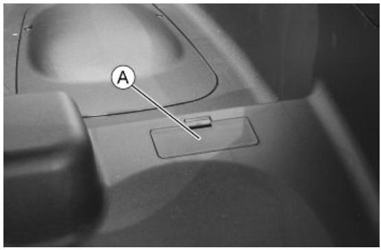
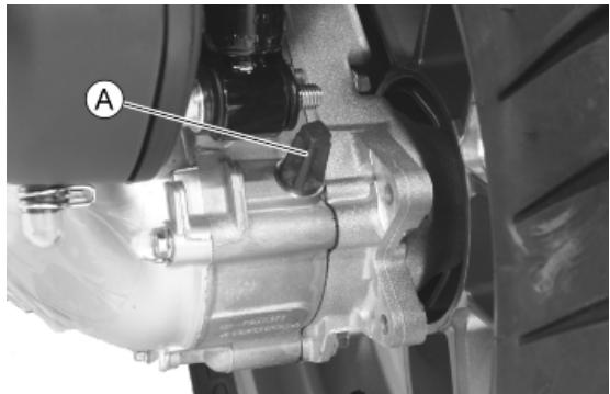
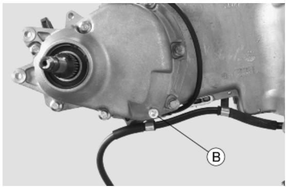
Vehicle identification
To read the chassis prefix, lift the saddle and remove the lid «A».
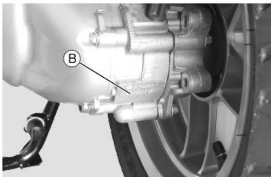
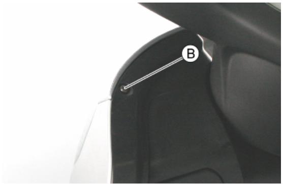
The engine prefix «B» is stamped near the lower support of the rear left shock absorber.
VEHICLE IDENTIFICATION
| Specification | Desc./Quantity |
| Chassis prefix | M62200 |
| Engine prefix | M622M |
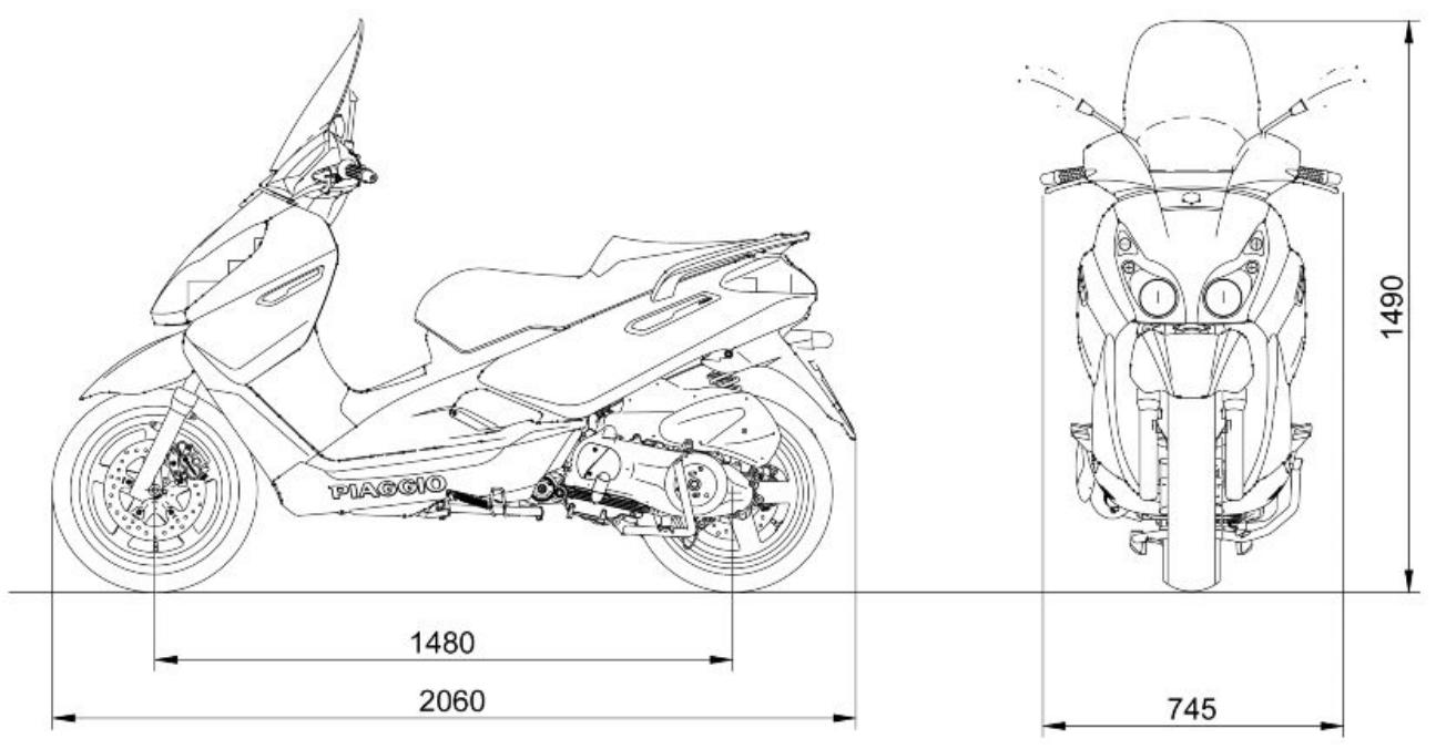
Dimensions and mass
VEHICLE EARTHING
| Specification | Desc./Quantity |
| Kerb weight | 162 kg |
| Maximum weight allowed | 360 kg |
Engine
| Specification | ENGINE Desc./Quantity |
| Type | Single-cylinder, 4-stroke |
| Cubic capacity | 244 cm³ |
| Bore x Stroke | 72 x 60 mm |
| Compression ratio | 11 ± 0.5 : 1 |
| Engine idle speed | 1,700 ± 100 rpm |
| Timing system | 4 valves, single overhead camshaft, chain-driven. |
| Valve clearance | Inlet: 0.10 mm Outlet: 0.15 mm |
| Max. Power | 16.3 kW at 8,750 rpm |
| MAX. torque | 11.2 Nm at 8,500 rpm |
| Lubrication | Engine lubrication with lobe pump (inside crank-case) controlled by a chain with double filter: mesh and paper. |
| Lubrication pressure | 4 bar |
CHAR - 4
| Specification | Desc./Quantity |
| Minimum lubrication pressure (100°C) | 0.8 bar |
| Fuel supply | Electronic injection with Ø 32-mm throttle body and electric fuel pump. |
| Cooling | Forced coolant circulation system. |
| Fuel | Unleaded petrol (95 RON) |
| Exhaust muffler | Absorption-type exhaust muffler with 3-way catalytic converter and lambda probe. |
| Emission regulations | EURO 3 |
Transmission
| Transmission | TRANSMISSION |
| Specification | Desc./Quantity |
| Transmission | Automatic expandable pulley variator with torque server, V belt, dry self-ventilating automatic cen-trifugal clutch and transmission housing with forced air circulation. |
| Final reduction | Gear reduction unit in oil bath. |
Capacities
| CAPACITY |
| Specification | Desc./Quantity |
| Engine oil | 1.3 l |
| Transmission oil | 250 cm³ |
| Cooling system fluid | ~ 2 l |
| Fuel tank (reserve) | ~ 12 l (~2 l) |
| Fork oil (quantity per stem) | 133 cm³ |
Electrical system
| ELECTRICAL SYSTEM |
| Specification | Desc./Quantity |
| Start-up | Electric |
| Ignition | Electronic inductive discharge ignition, high efficiency, with separate HV coil. |
| Ignition advance | α/N three-dimensional map managed by control unit |
| Spark plug | CHAMPION RG 4 PHP |
| Alternative spark plug | - |
| Battery | 12V-12Ah |
| Generator | In alternating current |
Frame and suspensions
FRAME AND SUSPENSIONS
| Specification | Desc./Quantity |
| Chassis | Tubular and sheet steel. |
| Front suspension | Hydraulic telescopic fork with Ø 35 mm stem |
| Front suspension travel | 94 mm |
| Rear suspension | Two double-acting shock absorbers, adjustable to four positions at preloading. |
| Rear suspension travel | 89 mm |
Brakes
BRAKES
| Specification | Desc./Quantity |
| Front brake | Ø 260 disc brake with hydraulic control activated by handlebar right lever. |
| Rear brake | Ø 240 mm disc brake with hydraulic control activated by the handlebar left-side lever. |
Wheels and tyres
WHEELS AND TYRES
| Specification | Desc./Quantity |
| Wheel rim type | Light alloy rims. |
| Front rim | 14" x 3.50 |
| Rear rim | 13" x 3.50 |
| Front tyre | Tubeless, 120/70-14" 55P |
| Rear tyre | Tubeless, 140/60 - 13" 63P |
| Front tyre pressure (with passenger) | 2 bar (2 bar) |
| Rear tyre pressure (with passenger) | 2.2 bar (2.5 bar) |
Tightening Torques
STEERING
| Name | Torque in Nm |
| Fixing screws for handlebar control assembly U-bolts | 7 ÷ 10 |
| Steering tube upper ring nut | 40 ÷ 45 |
| Steering tube lower ring nut | 14 ÷ 17 |
| Handlebar fixing screw | 43 ÷ 47 |
CHASSIS
| Name | Torque in Nm |
| Stand fixing bolt | 40 ÷ 45 |
| Engine and vehicle side swinging arm junction bolt | 33 ÷ 41 |
| Engine-swinging arm bolt | 64 - 72 |
| Body shell - Swinging arm pin | 76 ÷ 83 |
| Screw fixing the silent-block support plate to the body | 42 ÷ 52 |
FRONT SUSPENSION
| Name | Torque in Nm |
| Fork leg screw | 6 ÷ 7 |
| Front wheel shaft | 45 ÷ 50 |
| Fork plate screw | 25 ÷ 34 |
| Hydraulic rod fixing screw | 25 ÷ 35* |
| Stem support clamp tightening screws | 20 ÷ 25 |
| Fork locking screws cap | 15 ÷ 30 |
FRONT SUSPENSION
| Product | Description | Specifications |
| (*) Loctite 243 | Medium strength threadlock | Apply LOCTITE 243 medium-strength threadlock |
REAR SUSPENSION
| Name | Torque in Nm |
| Upper shock absorber clamp | 33 ÷ 41 |
| Shock absorber lower clamp | 33 ÷ 41 |
| Shock absorber-crankcase attachment bracket | 20 ÷ 25 |
| Rear wheel axle | 104 ÷ 126 |
| Muffler arm clamping screws | 27 ÷ 30 |
| Silencer - muffler supporting arm fixing screws | 24 ÷ 27 |
| Lambda probe clamp on exhaust manifold | 40 ÷ 50 |
| Manifold - muffler diaphragm tightening clamp | 16 ÷ 18 |
FRONT BRAKE
| Name | Torque in Nm |
| Oil bleed screw | 12 - 16 |
| Brake disc screws | 8 ÷ 10 |
| Brake fluid pipe-calliper fitting | 20 ÷ 25 |
| Brake fluid pump - hose fitting | 16 ÷ 20 |
| Screw tightening calliper to the support | 20 ÷ 25 |
| Tightening screw for calliper support to the fork | 41 ÷ 51 |
REAR BRAKE
| Name | Torque in Nm |
| Oil bleed screw | 12 - 16 |
| Brake disc screws | 8 ÷ 10 |
| Rear brake calliper-pipe fitting | 20 ÷ 25 |
| Rear brake pump-pipe fitting | 16 ÷ 20 |
| Screw tightening calliper to the support | 42 ÷ 52 |
REAR BRAKE
| Product | Description | Specifications |
| (°) Loctite 243 | Medium strength threadlock | Apply LOCTITE 243 medium-strength threadlock |
FLYWHEEL
| Name | Torque in Nm |
| Flywheel cover screw | 11 ÷ 13 |
| Stator assembly screws | 3 - 4 (Apply LOCTITE 242 medium-strength threadlock) |
| Flywheel nut (250) | 94 ÷ 102 |
| Pick-Up clamping screws | 3 ÷ 4 |
| Screw fixing freewheel to flywheel | 13 ÷ 15 |
LUBRICATION
| Name | Torque in Nm |
| Hub oil drainage plug | 15 ÷ 17 |
| Oil filter on crankcase fitting | 27 ÷ 33 |
| Engine oil drainage plug/mesh filter | 24 ÷ 30 |
| Oil filter | 4 ÷ 6 |
| Oil pump cover screws | 7 ÷ 9 |
| Screws fixing oil pump to the crankcase | 5 - 6 |
| Oil pump control crown screw | 10 ÷ 14 |
| Oil pump cover plate screws | 4 ÷ 6 |
| Oil sump screws | 10 ÷ 14 |
| Minimum oil pressure sensor | 12 ÷ 14 |
CYLINDER HEAD
| Name | Torque in Nm |
| Spark plug | 12 ÷ 14 |
| Head cover screws | 6 ÷ 7 |
| Nuts fixing head to cylinder | 7±1 + 10±1 + 270° |
| Head fixing side screws | 11 ÷ 12 Nm |
| Starter ground screw | 7 ÷ 8.5 |
| Tappet set screw lock nut | 6 ÷ 8 |
| Inlet manifold screws | 11 ÷ 13 |
| Timing chain tensioner slider screw | 10 ÷ 14 |
| Starter ground support screw | 11 ÷ 15 |
| Timing chain tensioner support screw | 11 ÷ 13 |
| Timing chain tensioner central screw | 5 - 6 |
| Camshaft retention plate screw | 4 ÷ 6 |
TRANSMISSION
| Name | Torque in Nm |
| Belt support roller screw | 11 ÷ 13 |
| Clutch unit nut on driven pulley | 45 ÷ 50 |
| Drive pulley nut | 75 ÷ 83 |
| Transmission cover screws | 11 ÷ 13 |
| Driven pulley shaft nut | 54 ÷ 60 |
| Rear hub cap screws | 24 ÷ 27 |
CRANKCASE AND CRANKSHAFT
| Name | Torque in Nm |
| Internal engine crankcase bulkhead (transmis-sion-side half shaft) screws | 4 ÷ 6 |
| Engine-crankcase coupling screws | 11 ÷ 13 |
| Starter motor screws | 11 ÷ 13 |
| Crankcase timing cover screws | 3.5 - 4.5 (Apply LOCTITE 242 medium-strength threadlock) |
COOLING
| Name | Torque in Nm |
| Water pump rotor cover | 3 ÷ 4 |
| Thermostat cover screws | 3 ÷ 4 |
| Bleed screw: | 3 |
Overhaul data
Assembly clearances
Cylinder - piston assay.
ENGINE COUPLING CATEGORY
| Name | Initials | Cylinder | Piston | Play on fitting |
| Cylinder | M | 72.01 ÷ 72.017 | 71.953 ÷ 71.960 | 0.050 - 0.064 |
| Cylinder | N | 72.017 ÷ 72.024 | 71.960 ÷ 71.967 | 0.050 - 0.064 |
| Piston | O | 72.024 ÷ 72.031 | 71.967 ÷ 71.974 | 0.050 - 0.064 |
| Piston | P | 72.031 ÷ 72.038 | 71.974 ÷ 71.981 | 0.050 - 0.064 |
Crankcase - crankshaft - connecting rod
CRANKSHAFT
| Titolo | Durata/Valore | Testo Breve (< 4000 car.) | Indirizzo Imagine |
| Crankshaft | | Crankshaft to crankcase axial clearance | |
Crankshaft to crankcase axial clearance
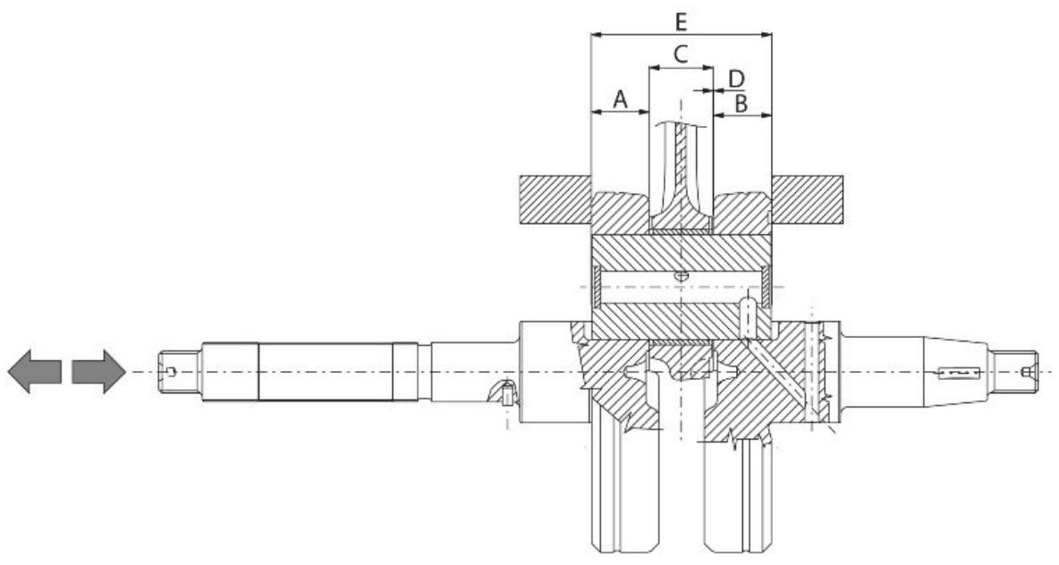
CRANKSHAFT/ CRANKCASE AXIAL CLEARANCE
| Name | Description | Dimensions | Initials | Quantity |
| Half-shaft, trans-mission side | | 16.6 +0-0.05 | A | D = 0.20 - 0.50 |
| Flywheel-side half-shaft | | 16.6 +0-0.05 | B | D = 0.20 - 0.50 |
| Connecting rod | | 18 -0.10 -0.15 | C | D = 0.20 - 0.50 |
| Spacer tool | | 51.4 +0.05 | E | D = 0.20 - 0.50 |
Slot packing system
Characteristic
Compression ratio
$$
1 0. 5 \div 1 1. 5: 1
$$
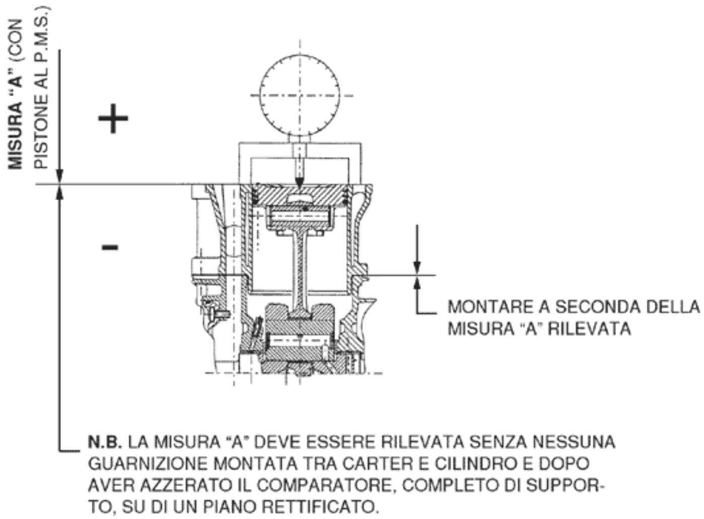
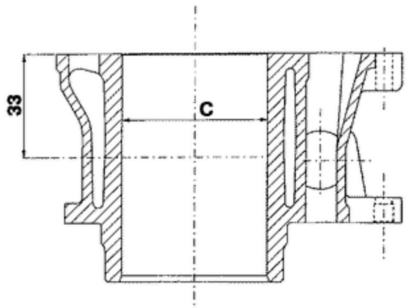
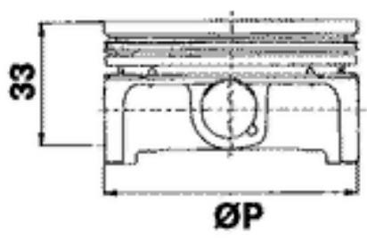
Measurement "A" to be taken is a value of piston re-entry, it indicates by how much the plane formed by the piston crown falls below the plane formed by the top of the cylinder. The further the piston falls inside the cylinder, the less the base gasket to be applied (to recover the compression ratio) and vice versa.
N.B.
MEASUREMENT "A" MUST BE TAKEN WITHOUT ANY GASKET FITTED BETWEEN THE CRANKCASE AND CYLINDER AND AFTER RESETTING THE GAUGE, EQUIPPED WITH A SUPPORT, ON A GROUND PLANE
ENGINE 250 SHIMMING
| Name | Measure A | Thickness |
| shimming | 3.70 - 3.60 | 0.4 ± 0.05 |
| shimming | 3.60 - 3.40 | 0.6 ± 0.05 |
| shimming | 3.40 - 3.30 | 0.8 ± 0.05 |
Products
RECOMMENDED PRODUCTS TABLE
| Product | Description | Specifications |
| AGIP ROTRA 80W-90 | Rear hub oil | SAE 80W/90 Oil that exceeds the requirements of API GL3 specifications |
| AGIP CITY HI TEC 4T | Oil to lubricate flexible transmissions (throttle control) | Oil for 4-stroke engines |
| AGIP FILTER OIL | Oil for air filter sponge | Mineral oil with specific additives for increased adhesiveness |
| AGIP GP 330 | Grease for brake levers, throttle | White calcium complex soap-based spray grease with NLGI 2; ISO-L-XBCIB2 |
| AGIP CITY HI TEC 4T | Engine oil | SAE 5W-40, API SL, ACEA A3, JASO MA Synthetic oil |
| AGIP BRAKE 4 | Brake fluid | FMVSS DOT4 Synthetic fluid |
| SPECIAL AGIP PERMANENT fluid | coolant | Monoethylene glycol-based anti-freeze fluid, CUNA NC 956-16 |
UNIT OF MEASUREMENT - CONVERSION - ENGLISH SYSTEM AND INTERNATIONAL SYSTEM (IS).
| Specification | Desc./Quantity |
| 1 Inch (in) | 25.4 Millimetres (mm) |
| 1 Foot (ft) | 0.305 Meter (m) |
| 1 Mile (mi) | 1.609 Kilometre (km) |
| 1 US Gallon (USgal) | 3.785 Litre (l) |
| 1 Pound (lb) | 0.454 Kilogram (kg) |
| 1 Cubic inch (in³) | 16.4 Cubic centimetres (cm³) |
| 1 Foot pound (ft lb) | 1.356 Newton meter (Nm) |
| 1 Miles per hour (mi/h) | 1.602 Kilometres per hour (km/h) |
| 1 Pound per square inch (PSI) | 0.069 (bar) |
| 1 Fahrenheit (°F) | 32+(9/5) Celsius (°C) |
INDEX OF TOPICS
TOOLING
TOOL
APPROPRIATE TOOLS
| Stores code | Description |
| 001330Y | Tool for fitting steering seats | |
| 001467Y014 | Pliers to extract ø 15-mm bearings | |
| 005095Y | Engine support | |
| 002465Y | Pliers for circlips | |
| 006029Y | Punch for fitting fifth wheel seat on steering tube | |
| 020004Y | Punch for removing fifth wheels from headstock | |
| 020055Y | Wrench for steering tube ring nut | |
| Stores code | Description |
| 020074Y | Support base for checking crank-shaft alignment |
| 020150Y | Air heater support |
| 020151Y | Air heater |
| 020193Y | Oil pressure gauge |
| 020262Y | Crankcase splitting strip |
| 020263Y | Sheath for driven pulley fitting |
| 020306Y | Punch for assembling valve seal rings |
| 020329Y | MityVac vacuum-operated pump |
| 020330Y | Stroboscopic light for timing control |
| 020331Y | Digital multimeter |
| 020332Y | Digital rev counter |
| 020648Y | Single battery charger |
| 020335Y | Magnetic support for dial gauge |
| 020357Y | 32 x 35 mm adaptor |
| 020359Y | 42x47-mm adaptor |
| 020360Y | Adaptor 52 x 55 mm |
| 020363Y | 20 mm guide |
| 020375Y | Adaptor 28 x 30 mm |
| 020376Y | Adaptor handle |
| 020382Y | Valve coters equipped with part 012 removal tool |
| 020382Y011 | adapter for valve removal tool |
| 020393Y | Piston fitting band |
| 020412Y | 15 mm guide |
| Stores code | Description | |
| 020423Y | driven pulley lock wrench | |
| 020424Y | Driven pulley roller casing fitting punch | |
| 020426Y | Piston fitting fork | |
| 020431Y | Valve oil seal extractor | |
| 020434Y | Oil pressure control fitting | |
| 020444Y | Tool for fitting/ removing the driv-en pulley clutch | |
| Stores code | Description |
| 020456Y | Ø 24 mm adaptor |
| 020477Y | Adaptor 37 mm |
| 020483Y | 30 mm guide |
| 020489Y | Hub cover support stud bolt set |
| 020428Y | Piston position check support |
| 020460Y | Scooter diagnosis and tester |
| Stores code | Description | |
| 020621Y | HV cable extraction adaptor | |
| 020481Y | Control unit interface wiring | |
| 001467Y035 | Belle for OD 47-mm bearings | |
| 020626Y | Driving pulley lock wrench | |
| 001467Y013 | Pliers to extract ø 15-mm bearings | |
| 020627Y | Flywheel lock wrench | |
| 020467Y | Flywheel extractor | |
| 020454Y | Tool for fitting piston pin stops (200 - 250) | |
| 020622Y | Transmission-side oil guard punch | |
| 020480Y | Petrol pressure check set | |
| 020244Y | 15-mm diameter punch | |
| 020115Y | Ø 18 punch | |
| 020271Y | Tool for removing-fitting silent bloc | |
| 020638Y | 250 I. E. ENGINE - ABS SOFT-WARE | |
| 020469Y | Reprogramming kit for scooter diagnosis tester | |
| 020487Y | Fork oil seal extractor | |
| 020458Y | Puller for lower bearing on steering tube | |
INDEX OF TOPICS
MAINTENANCE
MAIN
Maintenance chart
EVERY 2 YEARS
60
Action
Coolant - change
Brake fluid - change
AFTER 5,000 KM; 25,000 KM; 35,000 KM; 55,000 KM; 65,000 KM
10'
Action
Engine oil - level check/ top-up
Brake pads - check condition and wear
AFTER 10,000 KM; 50,000 KM; 70,000 KM
Action
Driven pulley roller casing - Greasing
Safety locks - check
Driving belt - Check
Throttle lever - adjustment
Air filter - clean
Engine oil - change
Electrical system and battery - check
Coolant level - check
Brake fluid level - check
Engine oil - replacement
Brake pads - check condition and wear
Sliding block / variable speed rollers - change
Tyre pressure and wear - check
Vehicle and brake test - road test
Hub oil - check
Suspensions - check
Steering - Check
AFTER 15,000 KM; 45,000 KM; 75,000 KM
45'
Action
Engine oil - level check/ top-up
Brake pads - check condition and wear
AFTER 20,000 KM; 40,000 KM; 80,000 KM
150
Action
Driven pulley roller casing - Greasing
Spark plug - replacement
Driving belt - replacement
Throttle lever - adjustment
Air filter - clean
Engine oil - change
Valve clearance - check
Electrical system and battery - check
MAIN - 2
Action
30,000 KM
| Coolant level - check |
| Brake fluid level - check |
| Engine oil - replacement |
| Brake pads - check condition and wear |
| Sliding block / variable speed rollers - change |
| Tyre pressure and wear - check |
| Vehicle and brake test - road test |
| Hub oil - change |
| Suspensions - check |
| Steering - Check |
140
Action
60,000 KM
| Driven pulley roller casing - Greasing |
| Safety locks - check |
| Throttle lever - adjustment |
| Driving belt - Check |
| Air filter - clean |
| Engine oil - change |
| Electrical system and battery - check |
| Coolant level - check |
| Brake fluid level - check |
| Engine oil - replacement |
| Hub oil - check |
| Brake pads - check condition and wear |
| Sliding block / variable speed rollers - change |
| Tyre pressure and wear - check |
| Vehicle and brake test - road test |
| Suspensions - check |
| Steering - Check |
190
Action
| Driven pulley roller casing - Greasing |
| Spark plug - replacement |
| Driving belt - replacement |
| Throttle lever - adjustment |
| Air filter - clean |
| Engine oil - change |
| Valve clearance - check |
| Electrical system and battery - check |
| Coolant level - check |
| Brake fluid level - check |
| Engine oil - replacement |
| Hub oil - change |
| Brake pads - check condition and wear |
| Sliding block / variable speed rollers - change |
| Tyre pressure and wear - check |
| Vehicle and brake test - road test |
| Suspensions - check |
Steering - Check
Checking the spark advance
The ignition advance is determined electronically on the basis of parameters known by the control unit. For this reason it is not possible to declare the reference values based on the engine rpm. The ignition timing value is detectable any time using the diagnostic tester. It is possible to check whether the ignition advance determined by the system does in fact correspond with the value actually activated on the engine, by means of the stroboscopic light.
Proceed as follows:
- Remove the spark plug.
- Remove the transmission crankcase.
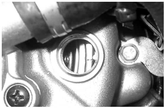
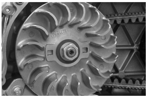
- Rotate the driving pulley fan until the reference marks between the flywheel and flywheel cover coincide as shown in the photograph.
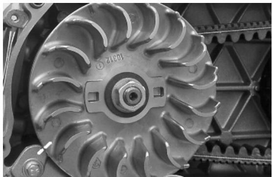
- Bring the reference mark onto the transmission side between the fan and the transmission cover as shown in the photograph.
- Refit the spark plug.
- Refit the plastic cap on the flywheel cover.
- Adjust the spark gap to the contact position (no reference mark visible) and install it on engine between the spark plug and spark plug cap
- Connect the induction calliper on the spark gap cable respecting the proper polarity (the arrow on the calliper must be pointing at the spark plug).
- Connect the diagnostic tester.
- Start the engine.
- Select the «parameter» function in this menu.
- Select the stroboscopic light command in the traditional four-stroke engine position (1 spark 2 revs).
- Check that the real values of rpm and ignition advance match those measured using the diagnostic tester.
If the values do not correspond, check:
- distribution timing
- revolution-timing sensor
- Injection control unit
020460Y Scooter diagnosis and tester
020330Y Stroboscopic light for timing control
020621Y HV cable extraction adaptor
Spark plug
To service the spark plug the engine must be cold; proceed as follows:
- Remove the spark plug inspection lid placed on the right side of the vehicle by undoing the specified screw.
- Remove the spark plug cap.
- Remove the spark plug with the supplied wrench.
- Examine it carefully and replace it if the insulator is chipped or cracked.
- Measure electrode gap with a thickness gauge and, if necessary, adjust the gap by carefully bending the outer electrode forward or away.
- Make sure the sealing washer is in good conditions.
- Fit the spark plug, screw it manually and lock it to the prescribed torque with a spark plug spanner.
- Refit the spark plug inspection lid.
CAUTION
THE SPARK PLUG MUST BE REMOVED WHEN THE ENGINE IS COLD. REPLACE THE SPARK PLUG AS INDICATED IN THE SCHEDULED MAINTENANCE TABLE. USING NON-COM-PLYING IGNITION CONTROL UNITS OR
SPARK PLUGS OTHER THAN THOSE PRE-SCRIBED MAY SERIOUSLY DAMAGE THE ENGINE.
Characteristic
Spark plug
CHAMPION RG 4 PHP
Electrode gap
0.7-0.8 mm
Locking torques (N^*m)
Spark plug 12 ÷ 14
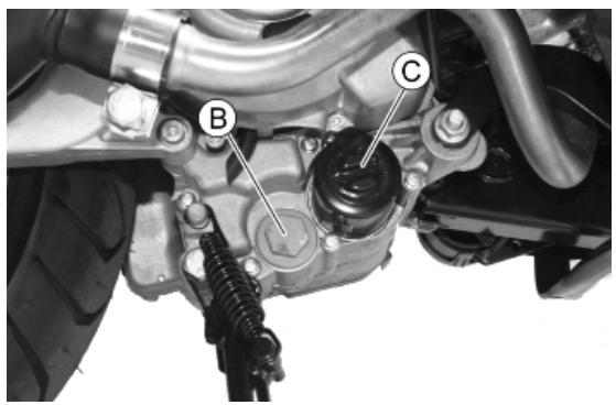
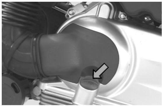
Hub oil
Check
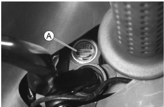
-Park the vehicle on its centre stand on flat ground;
- Remove the oil dipstick «A», dry it with a clean cloth and put it back into its hole tightening it
completely;
- Remove the dipstick and check that the oil level is slightly over the notch; if the level is below the notch indicated by the arrow, refill the hub with the right amount of oil.
-Screw up the oil dipstick again and make sure it is locked properly into place.
Replacement
- Unscrew the oil drainage cap "B" and drain out all the oil.
- Screw in the drainage plug again and fill the hub with the recommended oil.
Recommended products
AGIP ROTRA 80W-90 Rear hub oil
SAE 80W/90 Oil that exceeds the requirements of API GL3 specifications
Characteristic
Transmission oil
250 cm³
Locking torques (N^*m)
Hub oil drainage plug 15 ÷ 17

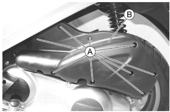
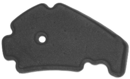
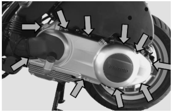
Air filter
To reach the air filter:
- Undo the nine screws «A».
- Remove the air-box cover «B»
Cleaning:
- Wash the sponge with water and mild soap.
- Dry it with a clean cloth and short blasts of compressed air.
- Soak it in a mixture of 50% petrol and 50% specified oil.
- Gently squeeze the filtering element with your hands but do not wring it; allow it to drip dry and then refit.
CAUTION

IF THE VEHICLE IS USED ON DUSTY ROADS IT IS NECESSARY TO CARRY OUT MAINTENANCE CONTROLS OF THE AIR FILTER TO AVOID DAMAGING THE ENGINE.
Recommended products
AGIP FILTER OIL Oil for air filter sponge
Mineral oil with specific additives for increased adhesiveness
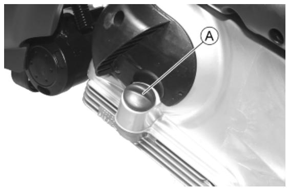
Engine oil
Replacement
Change oil and replace filter as indicated in the scheduled maintenance table.
- In order to facilitate oil drainage, unscrew the cap/ dipstick «A».

- Unscrew the mesh pre-filter drainage plug «B» on the flywheel side and let the oil drain off.
- Once all the oil has drained through the drainage hole, unscrew and remove the oil cartridge filter «C ».
Make sure the pre-filter and drainage plug O-rings are in good conditions. Lubricate them and refit the mesh filter and oil drainage plug, screwing them up to the specified torque.
Refit the new cartridge filter being careful to lubricate the O-ring before fitting it.
Add the recommended engine oil through plug «A». Then start up the vehicle, let it run for a few
minutes and shut it off. After five minutes check the level and if necessary top up without exceeding the MAX level. The cartridge filter must be replaced every time the oil is changed.
N.B.
THE ENGINE MUST BE HOT WHEN THE OIL IS CHANGED.
Recommended products
AGIP CITY HI TEC 4T Engine oil
SAE 5W-40 Synthetic oil that exceed the requirements of API SL, ACEA A3, JASO MA specifications
Characteristic
Engine oil
1.31
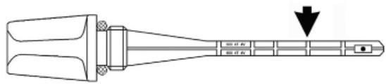
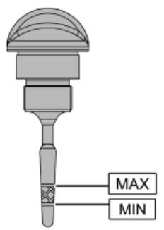
Check
This operation must be carried out with the engine cold and following the procedure below:
- Place the vehicle on its centre stand and on flat ground.
- Make sure the adjustment of the rear suspension is set to the minimum preloading position.
- Unscrew the cap/dipstick «A», dry it with a clean cloth and reinsert it, by screwing it in completely.
- Remove the cap/dipstick «A» again and check that the level is between the MAX and MIN marks. top-up, if required.
If the check is carried out after the vehicle has been used, and therefore with a hot engine, the level line will be lower; in order to carry out a correct check, wait at least 10 minutes after the engine has been stopped so as to get the correct level.
Oil top up
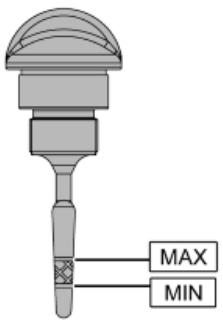
The oil should be topped up after having checked the level and in any case by adding oil without exceeding the MAX level indicated on the cap/ dipstick. Restoring the level from MIN to MAX requires approximately 400~cm^3 of oil.
Engine oil filter
The cartridge filter must be replaced every time the oil is changed. Use new oil of the recommended type for topping up and changing purposes.
Make sure the pre-filter and drainage plug O-rings are in good conditions. Lubricate them and refit the mesh filter and oil drainage plug, screwing them up to the specified torque. Refit the new cartridge filter being careful to lubricate the O-ring before the fitting. Change the engine oil.
Recommended products
AGIP CITY HI TEC 4T Engine oil
SAE 5W-40 Synthetic oil that exceed the requirements of API SL, ACEA A3, JASO MA specifications
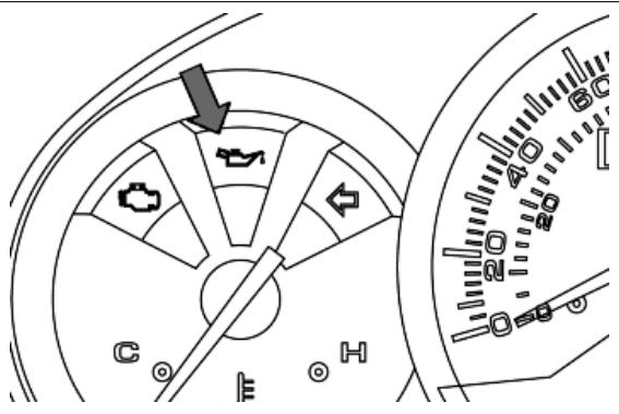
Oil pressure warning light
The vehicle is equipped with a warning light on the instrument panel that lights up when the key is turned to the «ON» position. However, this light should switch off once the engine has been started.
If the light turns on during braking, at idling speed or while turning a corner, it is necessary to check the oil level and the lubrication system.
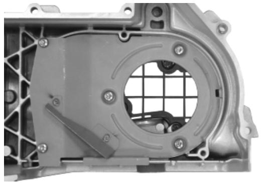
Checking the ignition timing
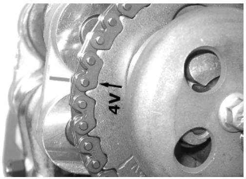
- Remove the plastic cap on the flywheel cover
- Turn the flywheel until the reference mark «T» on the rotor matches the reference mark on the fly-wheel cover as shown in the figure (TDC). Make sure that the 4V reference point on the camshaft control pulley is aligned with the reference point on the head as shown in the second figure. If the reference is opposite the indicator on the head, turn the crankshaft once more.

For the use of this reference mark, remove the spark plug and turn the engine in the direction that is the reverse of the normal direction using a calliper spanner applied to the camshaft command pulley casing.
Cooling system
Level check
Check coolant when the engine is cold and as indicated in the scheduled maintenance tables, following the steps below.
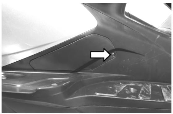
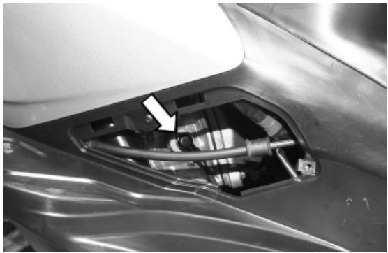
- Set the vehicle upright on the stand and remove the cover by undoing screw «A».
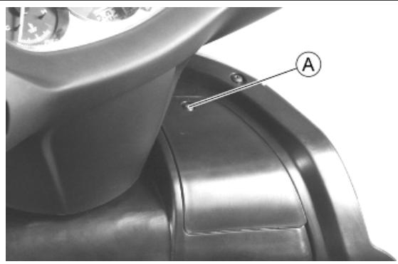
- Remove the expansion tank cover «B» by turning it anticlockwise.
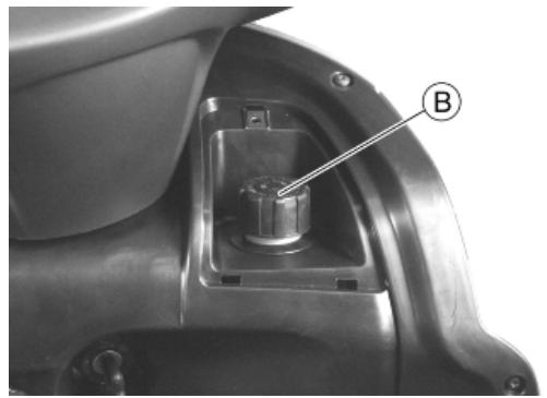
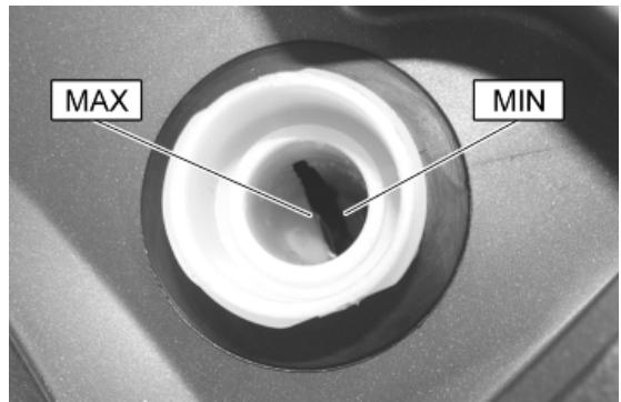
- Look inside the expansion tank and check that the level is between MIN and MAX. Top up if the coolant is below the MIN level.
If the level is not correct, proceed to top-up when the engine is cold. If it is necessary to top up the coolant frequently, or if the expansion tank is completely dry, you should look for the cause in the cooling system.
WARNING

IN ORDER TO AVOID BURNS, DO NOT UNSCREW THE EXPANSION TANK CAP WHILE THE ENGINE IS STILL HOT.
WARNING

IN ORDER TO AVOID HARMFUL FLUID LEAKS WHILE RIDING, IT IS IMPORTANT TO MAKE SURE THAT THE LEVEL DOES NOT EXCEED THE REFERENCE TONGUE TOO MUCH. IN ORDER TO GUARANTEE THE PROPER FUNCTION OF THE ENGINE, IT IS NECESSARY TO KEEP THE RADIATOR GRILLE CLEAN.
Recommended products
SPECIAL AGIP PERMANENT fluid coolant
Monoethylene glycol-based antifreeze fluid, CU-NA NC 956-16
Braking system
Level check
The front and rear brake fluid reservoirs are both positioned on the handlebars. Proceed as follows:
- Rest the vehicle onto the centre stand, with the handlebar centred.
- Check the fluid level through the sight glass «A».
A certain lowering of the level is caused by wear on the pads.
Top-up
Proceed as follows:
- Remove the rear-view mirrors.
- Working from both sides of the vehicle, undo the three screws «A» and remove the front frame.
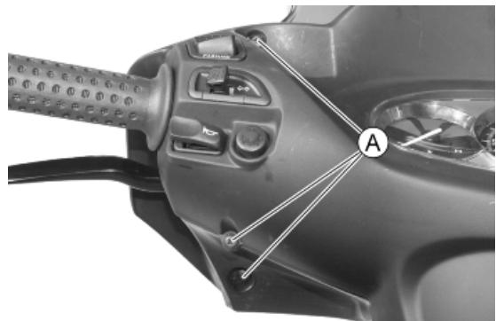
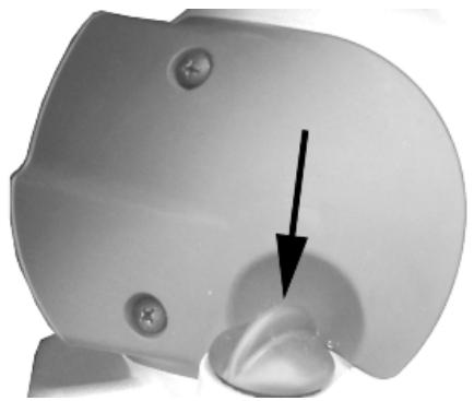
- Remove the windshield.
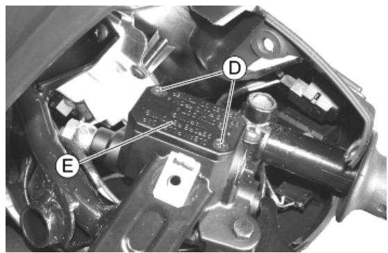
- Undo the screw «B» and remove the front handlebar cover «C» partially.
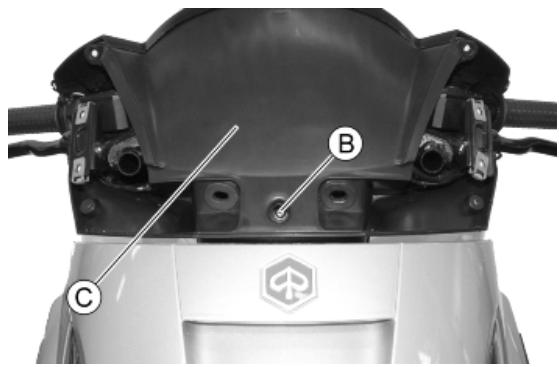
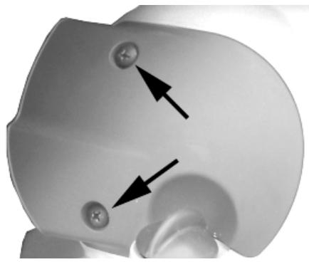
- Remove the cap «E» by loosening the two screws «D» and restore the fluid level by adding prescribed fluid type only, without exceeding the maximum level.
This operation applies to top up the rear brake pump. Follow the same procedure for the front one.
WARNING

ONLY USE DOT 4 CLASS BRAKE FLUIDS. COOLING SYSTEM FLUIDS ARE HIGHLY CORROSIVE. MAKE SURE THAT IT DOES NOT COME INTO CONTACT WITH THE PAINTWORK.
CAUTION

AVOID CONTACT OF BRAKE FLUID WITH EYES, SKIN, AND CLOTHING. IN CASE OF CONTACT, RINSE WITH WATER. THE BRAKING CIRCUIT FLUID IS HYGROSCOPIC, THAT IS, IT ABSORBS HUMIDITY FROM THE SURROUNDING AIR. IF THE HUMIDITY IN THE BRAKING FLUID EXCEEDS A CERTAIN VALUE, IT WILL LEAD TO INEFFICIENT BRAKING. NEVER USE BRAKING FLUID KEPT IN CONTAINERS THAT HAVE ALREADY BEEN OPENED, OR PARTIALLY USED.
Recommended products
AGIP BRAKE 4 Brake fluid
FMVSS DOT4 Synthetic fluid
Headlight adjustment
Proceed as follows:
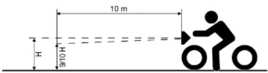
- Position the unloaded vehicle, in running order and with the tyres inflated to the prescribed pressure, onto a flat surface, 10 m away from a half-lit white screen; make sure the vehicle axis is perpendicular to the screen.
- Turn on the headlight and check that the borderline of the projected light beam should be lower than 9/10 of the distance from the ground to the centre of the vehicle's headlight, and higher than 7/10.
- Otherwise, adjust the headlight.
N.B.
THE ABOVE PROCEDURE COMPLIES WITH THE EUROPEAN STANDARDS REGARDING MAXIMUM AND MINIMUM HEIGHT OF LIGHT BEAMS. REFER TO THE STATUTORY REGULATIONS IN FORCE IN EVERY COUNTRY WHERE THE vehicle IS USED.
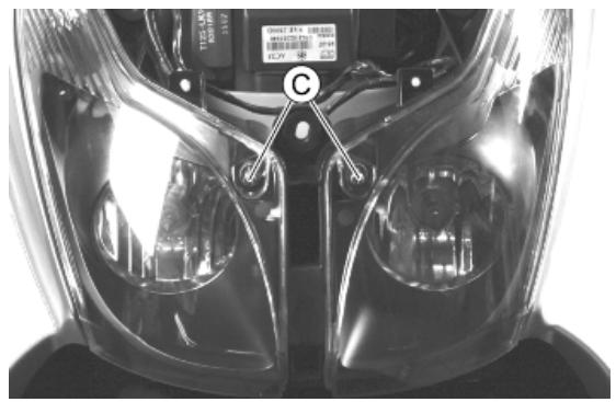
In order to adjust the light beams:
- Remove the PIAGGIO clip-on badge and undo the screw «A».
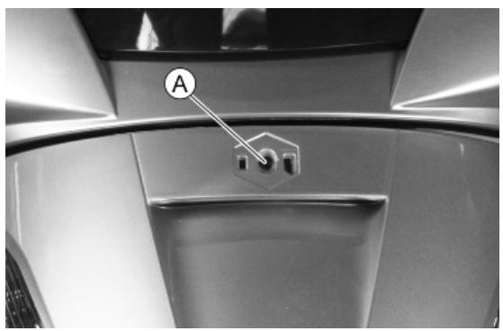
- Working on both sides of the vehicle, undo the screw «B» and remove the front headlight cover.
- Act on the screws «C» in order to aim the light properly.
INDEX OF TOPICS
TROUBLESHOOTING
TROUBL
This section makes it possible to find what solutions to apply when troubleshooting.
For each breakdown, a list of the possible causes and respective interventions is given.
Engine
POOR PERFORMANCE
| Possible Cause | Operation |
| Fuel pump | Check the injection load relay |
| Excess of encrustations in the combustion cham-ber | Descale the cylinder, the piston, the head and the valves |
| Incorrect timing or worn timing system elements | Time the system again or replace the worn parts |
| Muffler obstructed | Replace |
| Air filter blocked or dirty. | Remove the sponge, wash with water and car shampoo, then soak it in a mixture of 50% petrol and 50% specific oil. Press with your hand without squeezing, allow it to drip dry and refit. |
| Oil level exceeds maximum | Check for causes and fill to reach the correct level |
| Lack of compression parts, cylinder and valves wear | Replace the worn parts |
| Transmission belt worn | Replace |
| Inefficient automatic transmission | Check the rollers, the pulley movement and make sure the drive belt is in good conditions; replace the damaged parts and lubricate the moveable driven pulley with specific grease. |
| Clutch slipping | Check the clutch system and/or the bell and replace if necessary |
| Overheated valves | Remove the head and the valves, grind or replace the valves |
| Wrong valve adjustment | Adjust the valve clearance properly |
| Valve seat distorted | Replace the head assembly |
Starting difficulties
DIFFICULT STARTING
| Possible Cause | Operation |
| Rpm too low at start-up or engine and start-up system damaged | Check the starter motor, the system and the torque limiter |
| Incorrect valve sealing or valve adjustment | Inspect the head and/or restore the correct clearance |
| - Engine flooded. | Try starting-up with the throttle fully open. If the engine fails to start, remove the spark plug, dry it and before refitting, make the motor turn so as to expel the fuel excess taking care to connect the cap to the spark plug, and this in turn to the ground. If the fuel tank is empty, refuel and start up. |
| Air filter blocked or dirty. | Remove the sponge, wash with water and car shampoo, then soak it in a mixture of 50% petrol and 50% specific oil. Press with your hand without squeezing, allow it to drip dry and refit. |
TROUBL-2
| Possible Cause | Operation |
| Faulty spark plug or incorrect ignition advance | Replace the spark plug or check the ignition circuit components |
| Battery flat | Check the charge of the battery, if there are any sulphur marks, replace and use the new battery following the instructions shown in the chapter |
| Intake coupling cracked or clamps incorrectly tightened | Replace the intake coupling and check the clamps are tightened |
Excessive oil consumption/Exhaust smoke
EXCESSIVE CONSUMPTION
| Possible Cause | Operation |
| Wrong valve adjustment | Adjust the valve clearance properly |
| Overheated valves | Remove the head and the valves, grind or replace the valves |
| Misshapen/worn valve seats | Replace the head assembly |
| Worn cylinder, Worn or broken piston rings | Replace the piston cylinder assembly or piston rings |
| Worn or broken piston rings or piston rings that have not been fitted properly | Replace the piston cylinder unit or just the piston rings |
| Oil leaks from the couplings or from the gaskets | Check and replace the gaskets or restore the coupling seal |
| Worn valve oil guard | Replace the valve oil guard |
| Worn valve guides | Check and replace the head unit if required |
Insufficient lubrication pressure
POOR LUBRICATION PRESSURE
| Possible Cause | Operation |
| By-Pass remains open | Check the By-Pass and replace if required. Carefully clean the By-Pass area. |
| Oil pump with excessive clearance | Perform the dimensional checks on the oil pump components |
| Oil filter too dirty | Replace the cartridge filter |
| Oil level too low | Restore the level adding the recommended oil type |
Transmission and brakes
IRREGULAR CLUTCH PERFORMANCE OR SLIPPAGE
| Possible Cause | Operation |
| Faulty clutch | Check that there is no grease on the masses. Check that the clutch mass contact surface with the casing is mainly in the centre with equivalent characteristics on the three masses. Check that the clutch casing is not scored or worn in an anomalous way |
Insufficient braking
INEFFICIENT BRAKING SYSTEM
| Possible Cause | Operation |
| Inefficient braking system | Check the pad wear (1.5 min). Check that the brake discs are not worn, scored or warped. Check the correct level of fluid in the pumps and replace brake fluid if necessary. Check there is no air in the circuits; if necessary, bleed the air. Check that the front brake calliper moves in axis with the disc. |
| Fluid leakage in hydraulic braking system | Failing elastic fittings, plunger or brake pump seals, replace |
| Brake disc slack or distorted | Check the brake disc screws are locked; measure the axial shift of the disc with a dial gauge and with wheel mounted on the scooter. |
Brakes overheating
BRAKES OVERHEATING
| Possible Cause | Operation |
| Defective sliding of pistons | Replace the calliper. |
| Brake disc slack or distorted | Check the brake disc screws are locked; use a dial gauge and a wheel mounted on the vehicle to measure the axial shift of the disc. |
| Clogged compensation holes on the pump | Clean carefully and blast with compressed air |
| Re-inflated or glued rubber gaskets | Replace the calliper. |
Steering and suspensions
Heavy steering
STEERING HARDENING
| Possible Cause | Operation |
| Steering hardening | Check the tightening of the top and bottom ring nuts. If irregularities continue in turning the steering even after making the above adjustments, check the rotation seats and the steering fifth wheels. |
Excessive steering play
EXCESSIVE STEERING CLEARANCE
| Possible Cause | Operation |
| Torque not conforming | Check the tightening of the top and bottom ring nuts. If irregularities continue in turning the steering even after making the above adjustments, check the rotation seats and the steering fifth wheels. |
TROUBL - 4
Noisy suspension
NOISY SUSPENSION
| Possible Cause | Operation |
| Malfunctions in the suspension system | If the front suspension is noisy, check: locking tor-ques, headstock components, inspect forks. |
Suspension oil leakage
OIL LEAKAGE FROM SUSPENSION
| Possible Cause | Operation |
| Seal fault or breakage | Replace the shock absorber |
INDEX OF TOPICS
ELECTRICAL SYSTEM
ELESYS
Components arrangement
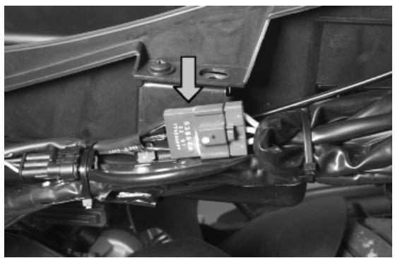
- Injection ECU: Remove the inspection flap placed in the helmet compartment to reach it.
- Stator: Remove the left side fairing to reach the connector.
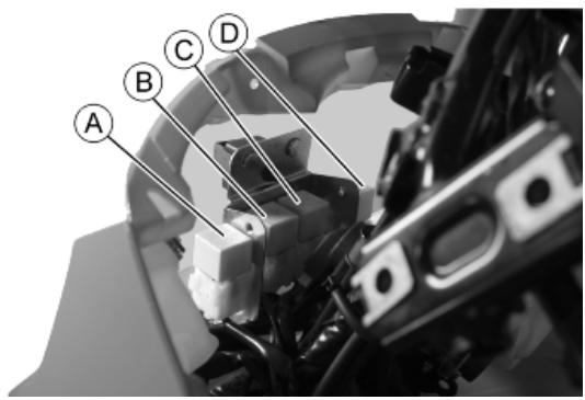
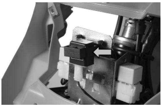
- Remote control switches: Remove the shield back plate to reach them.
KEY
A. Injection load remote control switch
B. Stop light remote control switch
C. Remote control switch for electric fan
D. Headlight remote control switch
- Turn indicators control device: Remove the front shield to reach it.
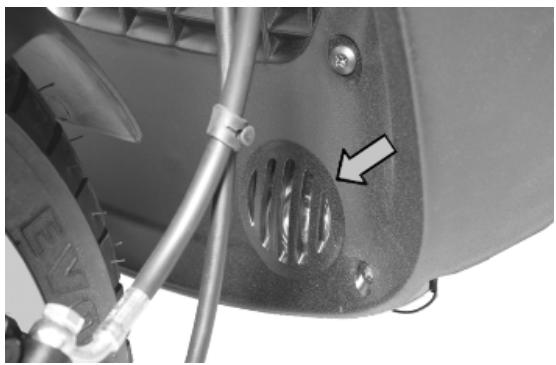
- Horn: Remove the left footrest to reach it.
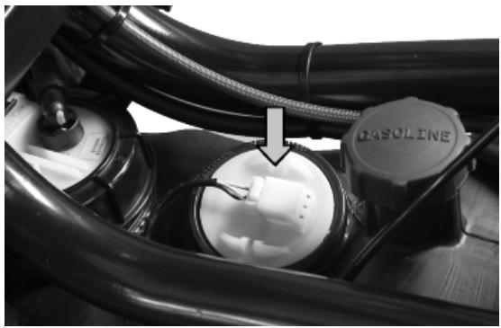
- Fuel level transmitter: Remove the central cover to reach it.
- Spark plug: Remove the lid placed on the right side fairing to reach it.
Characteristic
Spark plug
CHAMPION RG 4 PHP
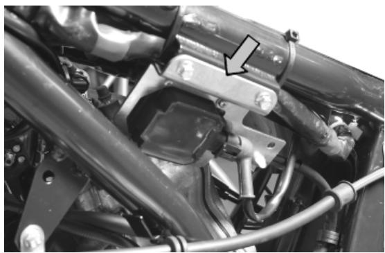
- HV coil: Remove the right side fairing to reach it.
Characteristic
HV coil resistance primary value:
0.9
HV coil secondary resistance value
3.4k
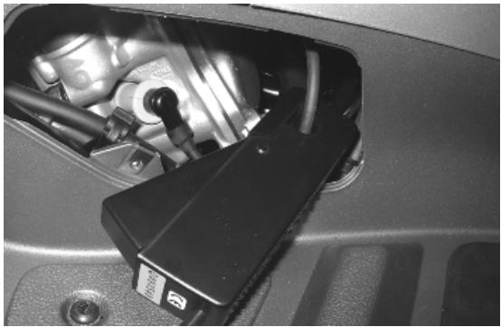
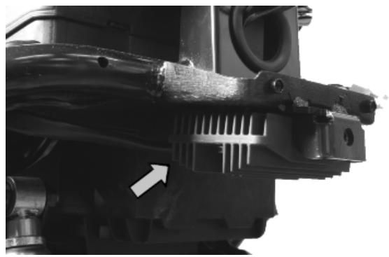
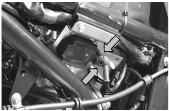
- Oil pressure sensor: Placed at the bottom at the back of the right side fairing.
- Start-up remote control switch: Remove the right side fairing to reach it.
- Voltage regulator: Remove the side fairings to reach it.
- Battery: Remove the battery cover placed in the helmet compartment to reach it.
Electric characteristic
Battery
12V 12Ah
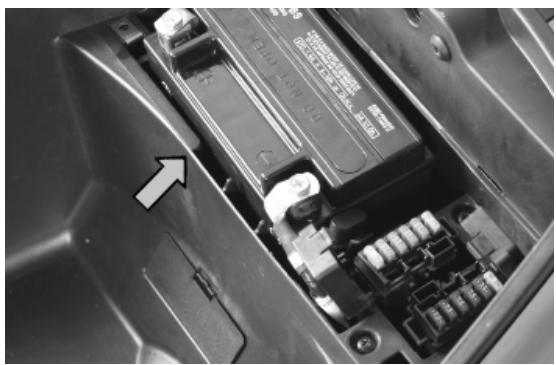
- Diagnostics socket: Remove the battery cover placed in the helmet compartment to reach it.
- Fuses: Remove the battery cover placed in the helmet compartment to reach it.
Punti di massa
There are three ground points in the electrical system:
A. Ground point on the chassis. Remove the left footrest to reach it.
B. Ground point on the chassis. Remove the left footrest to reach it.
C. Ground point on the engine. Placed at the bottom at the back of the left side fairing.
Checks and inspections
This section is devoted to the checks on the electrical system components.
Ignition circuit
No spark plug
WARNING ALL CONTINUITY TESTS MUST BE CARRIED OUT WITH THE CORRESPONDING CONNECTORS DISCONNECTED.
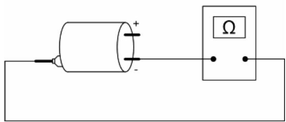
HV coil primary resistance value:
Disconnect the connector of the HV coil and measure the resistance between the two terminals.
Characteristic
HV coil resistance primary value:
0.9
HV coil secondary resistance value:
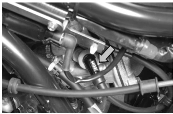
1) Disconnect the HV cable from the spark plug and measure the resistance between the spark plug cap and the HV coil negative terminal.
2) Disconnect the spark plug cap from the HV cable and measure the resistance between the HV cable end and the HV coil negative terminal (see figure).
3) Measure the resistance between the 2 ends of the spark plug cap.
Characteristic
HV coil secondary resistance value with spark plug cap
8.4 k
HV coil secondary resistance value:
3.4 k
Spark plug cap resistance value
5 k
Battery recharge circuit
The recharge system is provided with a three-phase alternator with permanent magneto flywheel.
The alternator is directly connected to the voltage regulator.
This, in its turn, is connected directly to the ground and the battery positive terminal passing through the 30A protective fuse.
The three- phase generator provides good recharge power and at low revs, a good compromise is achieved between generated power and idle stability.
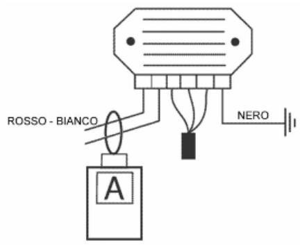
Stator check
WARNING
THE CHECK-UP CAN BE MADE WITH THE STATOR PROPERLY INSTALLED.
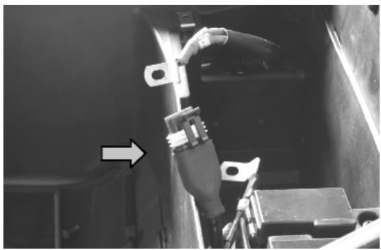
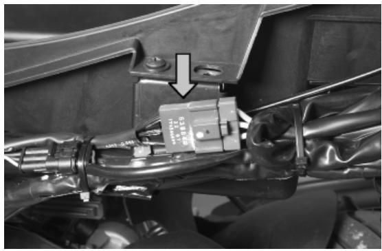
1) Disconnect the connector between stator and regulator with the three yellow cables as shown in the photograph.
2) Measure the resistance between each of the yellow terminals and the other two.
Characteristic
Stator phase resistance value
0.6
3) Check that there is insulation between the each yellow cable and the ground.
Voltage regulator check
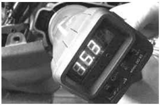
With a perfectly charged battery and lights off, measure voltage at the battery poles with a high running engine.
Voltage should not exceed 15 Volt.
In case higher voltages are detected, replace the regulator.
In case of voltage values lower than 14 Volt, check the stator and the corresponding cable harness.
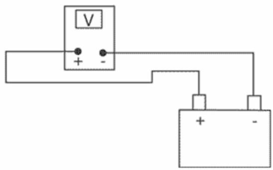
Electric characteristic
Control voltage
14÷ 15 V to 1500÷ 12000 rpm
Recharge system voltage check
Connect an ammeter induction clamp to the voltage regulator positive terminal, measure the battery voltage and, turning on the vehicles lights with engine off, wait for the voltage to set at about 12 V. Start the engine and measure the current generated by the system with lights on and a high running engine.
In case the generated current value is lower than 10A, repeat the test using a new regulator and/ or stator alternatively.
Starter motor
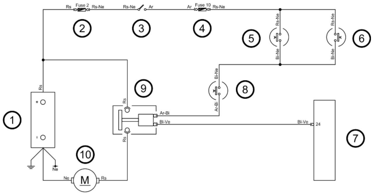
KEY
- Battery
- Fuse No. 2
- Key switch contacts
- Fuse No. 10
- Stop button on rear brake
- Stop button on front brake
- Injection ECU
- Starter button
- Start-up remote control switch
- Starter motor
WARNING
ALL CONTINUITY TESTS MUST BE CARRIED OUT WITH THE CORRESPONDING CONNECTORS DISCONNECTED.
If the starter motor does not operate correctly, proceed as follows:
1) Check the continuity of the Red cable between the battery and the start-up remote control switch.
Also check continuity between the latter and the starter motor.
2) Check the starter motor ground connection.
3) Check fuses No. 2 and No. 10.
4) Check key switch contacts.
5) Check stop buttons and the starter button.
6) Check the start-up remote control switch.
7) Check wiring continuity.
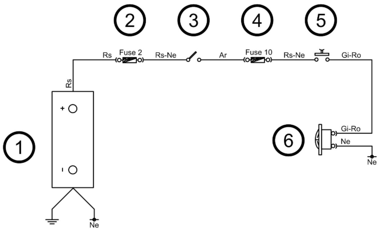
Horn control
KEY
- Battery
- Fuse No. 2
- Key switch contacts
- Fuse No. 10
- Horn button
- Horn
WARNING
ALL CONTINUITY TESTS MUST BE CARRIED OUT WITH THE CORRESPONDING CONNECTORS DISCONNECTED.
In case the horn does not operate correctly, proceed as follows:
1) Check fuses No. 2 and No. 10.
2) Check key switch contacts and horn button.
3) Check wiring continuity.
4) Check the horn ground connection.
Turn signals system check
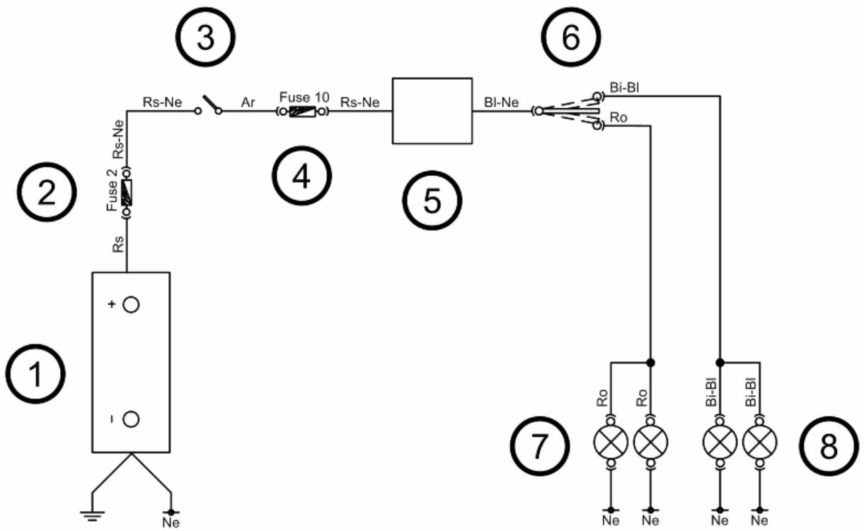
KEY
- Battery
- Fuse No. 2
- Key switch contacts
- Fuse No. 10
- Turn indicators control device
- Turn indicator switch
- Left turn indicator bulbs
- Right turn indicator bulbs
WARNING
ALL CONTINUITY TESTS MUST BE CARRIED OUT WITH THE CORRESPONDING CONNECTORS DISCONNECTED.
If the circuit does not work properly, proceed as follows:
1) Check that bulbs operate properly.
2) Check fuses No. 2 and No. 10.
3) Check key switch contacts.
4) With the key switch set to «ON», check if there is intermittent voltage between the output Blue-Black cable from the turn indicator control device and the ground lead.
5) If no voltage is detected, check cable harness continuity and, if necessary, restore it. If it is not damaged, replace the turn indicator control device.
6) Check the turn indicator switch.
7) Check turn indicator switch cable harness continuity.
8) Check the bulbs ground connection.
level indicators
WARNING
ALL CONTINUITY TESTS MUST BE CARRIED OUT WITH THE CORRESPONDING CONNECTORS DISCONNECTED.
If faults are detected:
1) With a multimeter, check resistance values between the White-Green cable and the Black cable of the fuel level transmitter by moving the arm with the float.
2) If the transmitter operates correctly but the indication on the instrument panel is not exact, check that the cable harnesses between them are not interrupted.
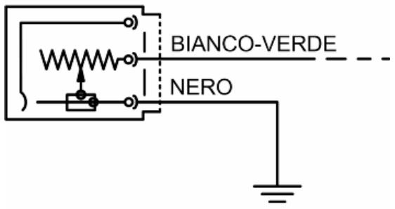
Electric characteristic
Resistance value when the tank is full
$$
< = 7 \Omega
$$
Resistance value when the tank is empty
$$
9 0 + 1 3 / - 3 \Omega
$$
Lights list
LIGHT BULB TABLE
| Specification | Desc./Quantity |
| 1 | High-beam light bulb | Type: HALOGEN (H7)
Power: 12V - 55W
Quantity: 1 |
| 2 | Low-beam bulb | Type: HALOGEN (H1)
Power: 12V - 55W
Quantity: 1 |
| 3 | Front tail light bulb | Type: ALL GLASS
Power: 12V - 5W
Quantity: 2 |
| 4 | Instrument panel bulb | Type: ALL GLASS
Power: 12V - 1.2W
Quantity: 3 |
| 5 | Front turn indicator bulb | Type: ALL GLASS
Power: 12V - 10W
Quantity: 1 RHS + 1 LHS |
| 6 | Rear turn indicator light bulb | Type: SPHERICAL
Power: 12V - 10W
Quantity: 1 RHS + 1 LHS |
| 7 | Tail light and stop light bulb | Type: SPHERICAL, TWIN-FILAMENT |
ELE SYS - 12
| Specification | Desc./Quantity |
| | Power: 12V - 5/21W
Quantity: 2 |
| 8 | License plate light bulb | Type: ALL GLASS
Power: 12V - 5W
Quantity: 1 |
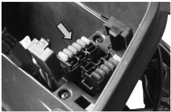
Fuses
The electrical system is fitted with twelve fuses divided between two fuse boxes, located in the battery compartment, for the protection of the various circuits in the system.
The chart shows the position and specifications of the fuses in the vehicle.
CAUTION

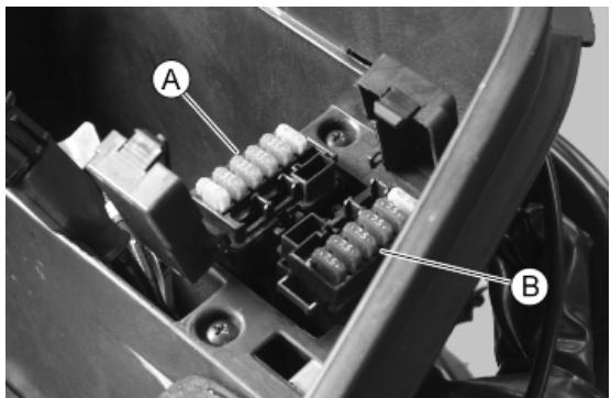
BEFORE REPLACING THE BLOWN FUSE, FIND AND SOLVE THE FAILURE THAT CAUSED IT TO BLOW. NEVER TRY TO REPLACE THE FUSE WITH ANY OTHER MATERIAL (E.G., A PIECE OF ELECTRIC WIRE).
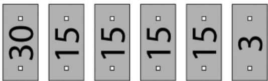
FUSES
| Specification | Desc./Quantity |
| 1 | Fuse No. 1 | Capacity: 30 A
Protected circuits: Battery recharge circuit. |
| 2 | Fuse No. 2 | Capacity: 15A
Protected circuits (live):Headlight remote control switch, high-beam light in flashing mode, fuses No. 7-8-9-10. |
| 3 | Fuse No. 3 | Capacity:15A |
| | Protected circuits: Light switch (via remote control) |
| 4 | Fuse No. 4 | Capacity: 15A
Protected circuits: Electric fan (via remote control) |
| 5 | Fuse No. 5 | Capacity: 15A
Protected circuits: Injection load (via remote control), injection ECU. |
| 6 | Fuse No. 6 | Capacity:3A
Protected circuits: Clock, pre-installation for antitheft device. |
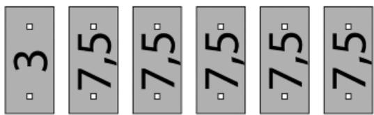
| 7 | Fuse No. 7 | Capacity:3A
Protected circuits (live): Pre-installation for antitheft device, instrument panel. |
| 8 | Fuse No. 8 | Capacity: 7.5 A
Protected circuits (live): ECU remote control, injection ECU, electric fan remote control. |
| 9 | Fuse No. 9 | Capacity: 7.5 A
Protected circuits (live): Position lights, license plate light, instrument panel lighting. |
| 10 | Fuse No. 10 | Capacity: 7.5 A
Protected circuits (live): Stop lights, start-up circuit, horn, turn indicators. |
| 11 | Fuse No. 11 | Capacity: 7.5 A
Protected circuits (live): High-beam light. |
| 12 | Fuse No. 12 | Capacity:7.5 A
Protected circuits (live):Low-beam light. |
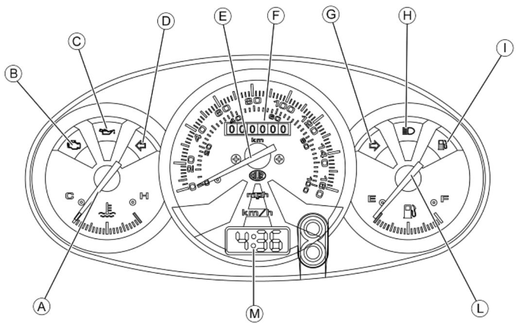
Dashboard
A = Coolant temperature gauge
B = Engine control telltale light and injection system failure warning light
F = Low oil pressure warning light
D = Left turn indicator warning light
E = Speedometer with twin scale (km/h and mph)
F = Odometer
G = Right turn indicator warning light
H = High-beam warning light
I = Low fuel warning light
L = Fuel gauge
M = Digital clock
Sealed battery
If the vehicle is provided with a sealed battery, the only maintenance required is the check of its charge and recharging, if necessary.
These operations should be carried out before delivering the vehicle, and on a six-month basis while the vehicle is stored in open circuit.
Besides, upon pre-delivery it is therefore necessary to check the battery charge and recharge it, if required, before storing the vehicle and, afterwards, every six months.
INSTRUCTIONS FOR THE RENEWAL RECHARGE AFTER OPEN-CIRCUIT STORAGE
1) Voltage check up
Before installing the battery on the vehicle, check the open circuit voltage with a regular tester.
- If voltage exceeds 12.60 V ,the battery can be installed without any renewal recharge.
- If voltage is below 12.60V , a renewal recharge is required as explained in 2).
2) Constant voltage battery charge mode
- Constant voltage charge equal to 14.40 ÷ 14.70V
-Initial charge voltage equal to 0.3 ÷ 0.5 for Nominal capacity
- Charge time:
10 to 12 h recommended
Minimum 6 h
Maximum 24 h
3) Constant current battery charge mode
- Charge current equal to 1/10 of the battery rated capacity
- Charge time: Maximum 5 h
Dry-charge battery
COMMISSIONING A NEW DRY-CHARGED BATTERY
- Remove the battery air pipe stop cap and each single element caps.
- Fill the battery with electrolyte of 1.270 + / - 0.01 kg / l density (corresponding to 31 + / - 1 Bé ) with an ambient temperature not below 15^ C , until it reaches the upper level indicated on the block.
- Tilt the battery slightly to remove any air bubbles formed during filling.
- Place the caps on each single element filling holes without screwing them and leave the battery to rest. During this stage, the battery is subjected to a gasification phenomenon and temperature increases.
- Let it rest until it reaches ambient temperature (this stage can take up to 60 minutes).
- Tilt the battery slightly to facilitate the elimination of any gas bubbles present inside; restore the level using the same filling electrolyte
Note: This is the last time that electrolyte can be added. Future top-ups should be done only with distilled water;
- Before 24 hours elapse, recharge the battery following these steps:
- Connect the battery charger terminals observing the correct polarity;
- Wit the battery charger drw. 020333Y and/or drw. 020334Y operate the battery charger control by selecting the position corresponding to that capacity;
- Otherwise, charge the battery with direct current equal to 1/10 of rated capacity (e.g. for a battery with a 9Ah rated capacity, the charging current should be 0.9-1.0A) for approximately a 4-6 hour charge.
Note: Batteries that have been stored for a long time may take a longer charging time. The battery chargers drw. 020333Y and drw. 020334Y have an automatic protection which interrupts the recharge after 12 hours to avoid battery harmful heating. In this case, a green LED turns on to indicate the activation of the safety system and not the end of the charge.
- Let the open circuit battery rest for approximately 4-6 hours; then check the off-load voltage using a standard tester.
- If the open-circuit voltage is higher or equal to 12.6V, the battery is charged adequately. Slightly shake or tilt the battery to eliminate any air bubbles formed during recharging.
- Check the electrolyte levels again, fill them with distilled water up to the upper level line if necessary, clean battery properly, close each single cell cap tightly and install it on the vehicle.
- If the voltage indicated is low, charge the battery another 4-6 hours in the way described above.
Note: With the battery charger drw. 020334Y, it is possible to check the battery charge level with the Check function. The value indicated on the display must be higher than the value indicated on the chart; otherwise, recharge the battery again in the same way indicated above.
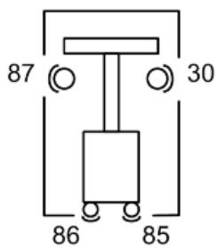
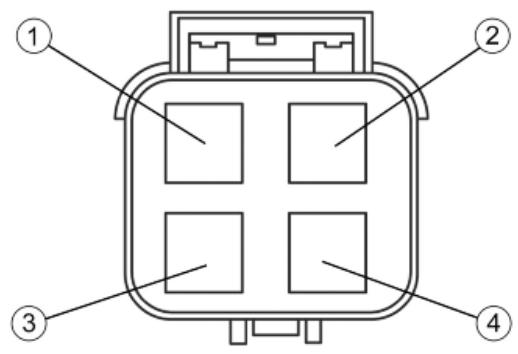
Controllo teleruttori
To check the operation of a remote control:
1) Check that, given regular conditions, there is no continuity between terminals 87 and 30.
2) Apply a 12V voltage to power terminals 86 and 85 of the remote control.
3) With the remote control fed, check that there is continuity between terminals 87 and 30.
4) If these conditions are not met, the remote control is surely damaged and, therefore, it should be replaced.
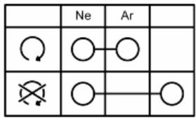
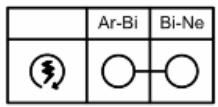
Controllo interruptori
To check buttons and switches, check that, according to their position, the continuity of contacts is correct as indicated in the following charts.
KEY
Ar: Orange Az: Sky Blue Bi: White Bl: Blue Gi: Yellow Gr: Grey Ma: Brown Ne: Black Ro: Pink Rs: Red Ve: Green Vi: Purple
ENGINE STOP SWITCH
LIGHT SWITCH
| Gr | Bi-Rs | Vi | Ma |
| ∅ | ○ | | ○ | |
| ∅ | ○ | | | ○ |
| ∅ FLASH | | ○ | ○ | |
TURN INDICATOR SWITCH
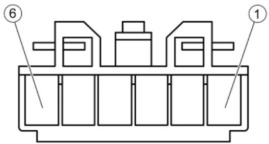
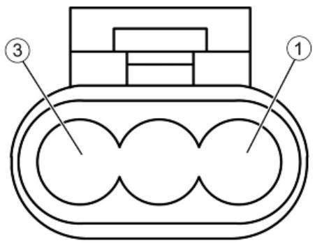
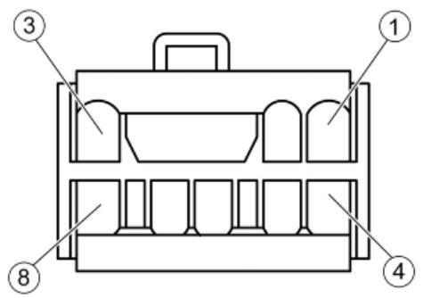
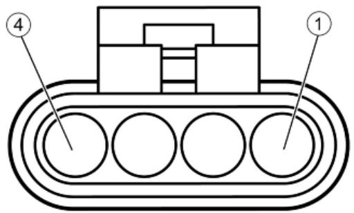
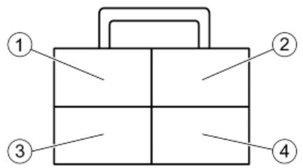
Connectors
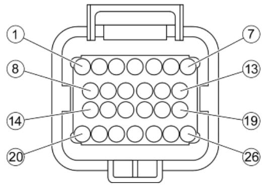
INSTRUMENT PANEL CONNECTOR «A»
- Low fuel warning light (Yellow-Green)
- Live supply (White-Red)
- High-beam warning light (Purple)
- Right turn indicator warning light (White-Blue)
- Fuel level indicator (White-Green)
- Instrument panel lighting (Yellow-Black)
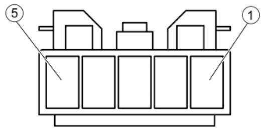
INSTRUMENT PANEL CONNECTOR «B»
- Ground (Black)
- Left turn indicator warning light (Pink)
- Coolant temperature signal (Blue-Black)
- Live supply (White-Red)
- Injection telltale light (Brown-Black)
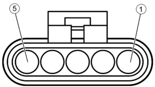
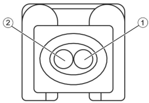
FUEL PUMP CONNECTOR
- Not connected
- Ground (Black)
- Not connected
- Not connected
- power via remote control (Black-Green)
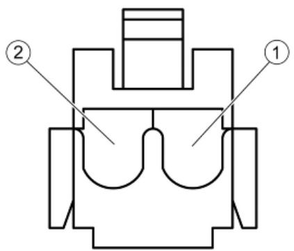
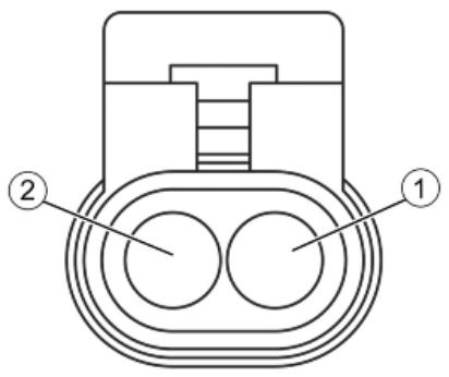
ELECTRIC FAN CONNECTOR
- Power via remote control (Red)
- Ground (Black)
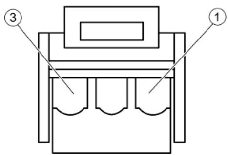
MAGNETO FLYWHEEL CONNECTOR
- Engine revolution sensor ECU positive (Red)
- Engine revolution sensor ECU negative (Brown)
- Oil pressure sensor (White-Pink)
ANTITHEFT DEVICE PRE-INSTALLATION CONNECTOR
- LHS Turn indicator bulbs (Pink)
- RHS Turn indicator bulbs (White-Blue)
- Ground (Black)
- Battery-powered (Blue-Red)
- Live supply (White-Red)
- Not connected
- Not connected
- Not connected
LAMBDA PROBE CONNECTOR
- Lambda probe ECU positive (Sky blue-Yellow)
- Lambda probe ECU negative (Sky blue-Black)
- Heater ECU negative (Sky blue-Red)
- Heater power via remote control (Black-Green)
VOLTAGE REGULATOR CONNECTOR
- Battery positive (Red)
- Ground (Black)
- Battery positive (Red)
- Ground (Black)
INJECTION ELECTRONIC CONTROL UNIT
- Injection telltale light (Brown-Black)
- Not connected
- Not connected
- Lambda probe negative (Sky blue-Black)
- Live supply (Red-Green)
- Battery-powered (Orange-Blue)
- Not connected
- Electric fan remote control (Green-White)
- Coolant temperature sensor (Yellow-Pink)
- Not connected
- Lambda probe positive (Sky blue-Yellow)
- Engine stop switch (Orange)
- Engine revolution sensor positive (Red)
- Injector negative (Yellow-Red)
- Engine revolution sensor negative (Brown)
- Diagnostics socket (Orange-Black)
- Not connected
- Ground (Black)
- Lights remote control (Black)
- Injection load remote control (Black-Purple)
- Lambda heater negative (Sky blue-Red)
- HV coil negative (Pink-Black)
- Not connected
- Start-up remote control switch (Blue-Green)
- Not connected
- Ground (Black)
INJECTOR CONNECTOR
- Power via remote control (Black-Green)
- Control unit negative (Yellow-Red)
HV COIL CONNECTOR
- Control unit negative (Pink-Black)
- Power via remote control (Black-Green)
FUEL LEVEL TRANSMITTER CONNECTOR
- Low fuel warning light (Yellow-Green)
- Ground (Black)
- Fuel level indicator (White-Green)
COOLANT TEMPERATURE SENSOR CONNECTOR
- Ground (Grey-Green)
- Ground (Black)
- Injection ECU (Yellow-Pink)
- Instrument panel (Sky blue-Black)
INDEX OF TOPICS
ENGINE FROM VEHICLE
ENGVE
This section describes the operations to carry out when removing the engine from the vehicle.
Exhaust assay. Removal
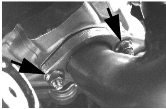
- Remove the Lambda probe from its support and disconnect it.
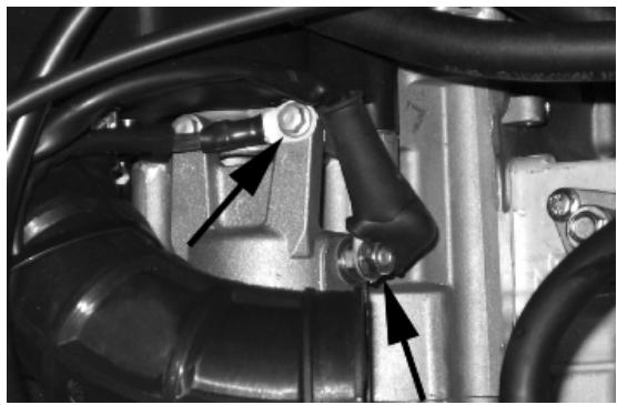
- Undo the two exhaust manifold fixings on the head. To undo the nuts fixing the muffler flange to the head properly, you must use a jointed wrench that enables you to get at the right nut as well, according to the direction of travel, that is difficult to get at with a traditional straight wrench.
- Undo the three screws fixing the muffler to the support arm.
Remove the full muffler unit.
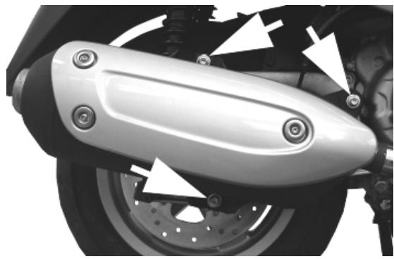
Remove the lambda probe from the manifold.
CAUTION: SHOULD IT BE NECESSARY TO REMOVE ONLY THE MUFFLER TIP, ALWAYS REPLACE THE GRAPHITE GASKET BETWEEN STUB AND TIP.
Removal of the engine from the vehicle
- Disconnect the battery
- Remove the engine cover inside the helmet compartment
- Remove the side panels
Remove the full muffler assembly.
CAUTION
THIS OPERATION MUST BE CARRIED OUT WHEN THE ENGINE IS COLD.
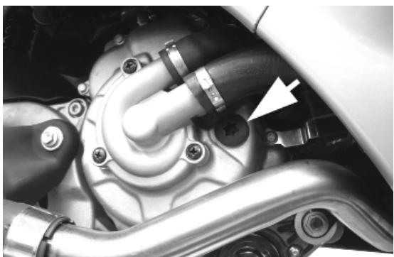
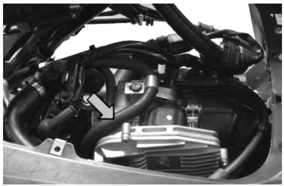
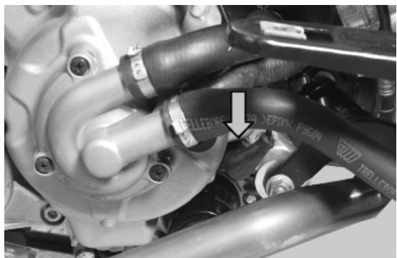
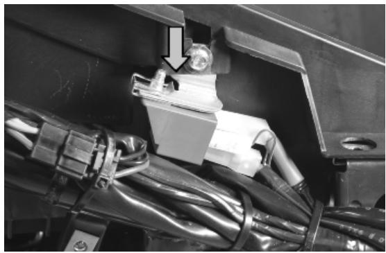
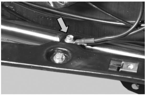
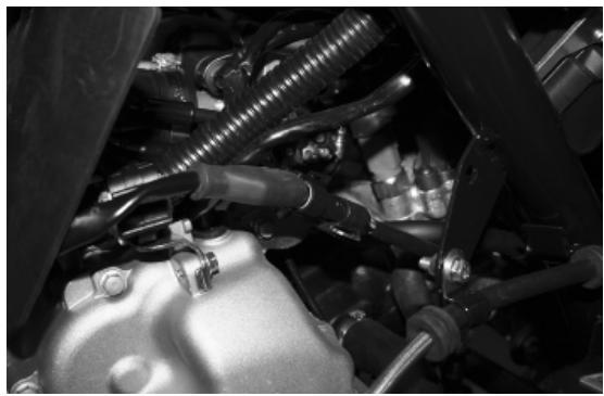
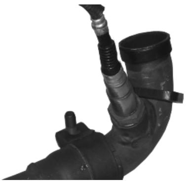
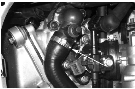
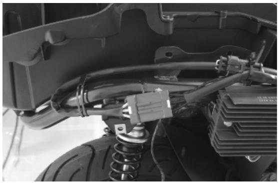
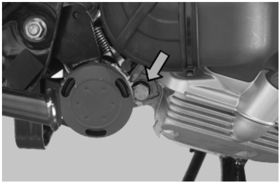
- Remove the pipe feeding coolant into the pump as shown in the photograph and then empty the system.
- Remove the engine-chassis ground lead.
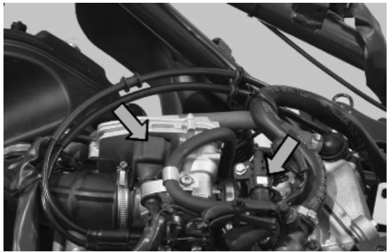
- Disconnect the fuel delivery and return pipes from the injector by removing the screw locking the retaining clamp.
- Disconnect the injector wiring and the throttle body control unit wiring.
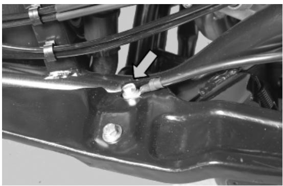
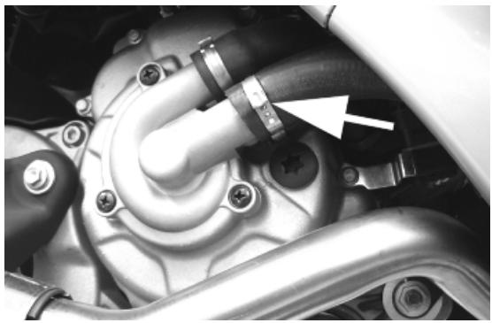
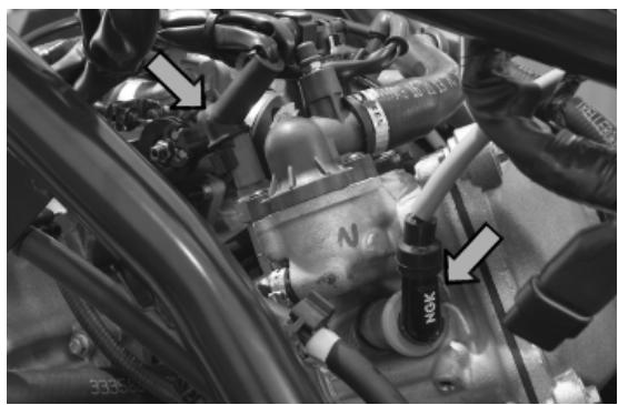
- Remove the coolant outlet pipe from the motor as indicated.
- Remove the spark plug cap.
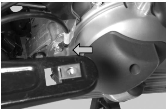
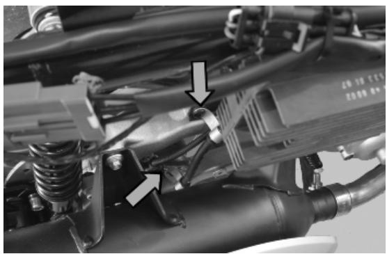
- Remove the coolant temperature sensor connector indicated in the photo.
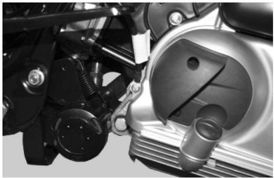
- Remove the throttle cables from the throttle body by undoing the nuts indicated in the photograph.
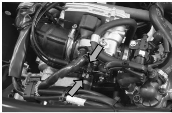
- Remove the positive and negative wiring from the starter motor as shown in the photo.
- Disconnect the connectors from the flywheel wiring as shown in the photo.
- Remove the cable from the retaining clip on the flywheel cover.
- Undo the fixing screw of the locking clamps of the brake pipe from the muffler supporting arm.
Muffler supporting arm removal
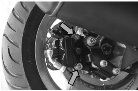
- Unscrew and remove the screw fixing the right-hand shock absorber to the supporting plate.
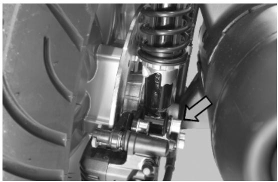
- Remove the cotter pin, the cap and unscrew the wheel axle nut. Operate the rear brake by pulling the left lever on the handlebar so that the axle does not turn.
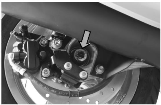
- Undo the 2 screws fixing the rear brake calliper.
- Remove the calliper and its pipes from the muffler supporting arm.
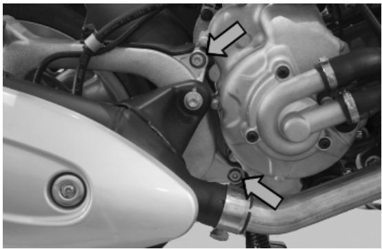
- Undo the 2 screws fixing the swinging arm to the engine.
- Remove the muffler support arm
-
Slide off the entire wheel with its disc from the wheel axle. Move the right shock absorber backwards to facilitate removing the wheel.
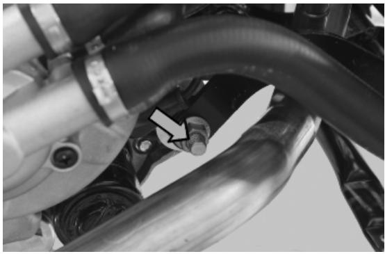
-
Use a jack to support the vehicle properly. Remove the engine-swinging arm fixing pin by undoing the nut and the head of the pin as shown in the photograph.
-
The engine is now free.
When refitting the engine onto the scooter, carry out the removal operations but in reverse order and respect the tightening torques shown in the Specifications Chapter.
-Check the engine oil level and if necessary top it up with the recommended type.
- Fill and bleed the cooling circuit.
- Check the functioning of the accelerator and the electrical devices.
CAUTION
PAY PARTICULAR ATTENTION TO POSITIONING THE THROTTLE COMMAND TRANSMISSION PROPERLY.
INDEX OF TOPICS
ENGINE
ENG
This section describes the operations to be carried out on the engine and the tools to be used.
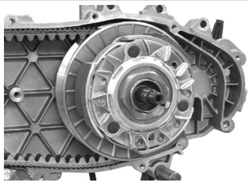
Automatic transmission
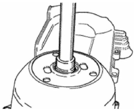
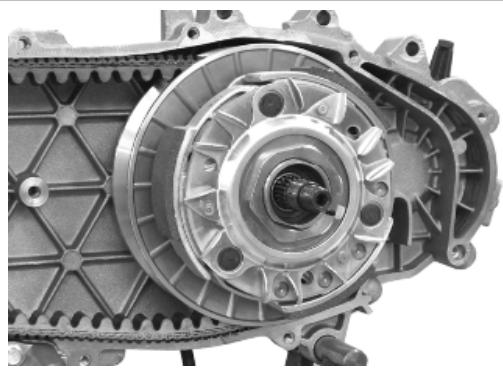
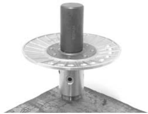
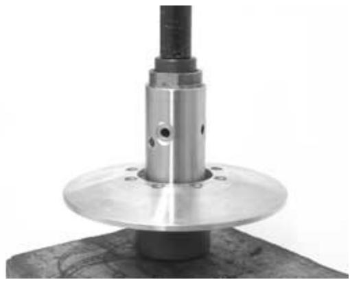
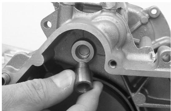
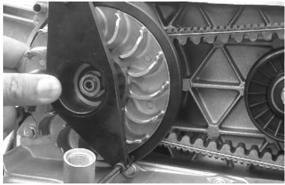
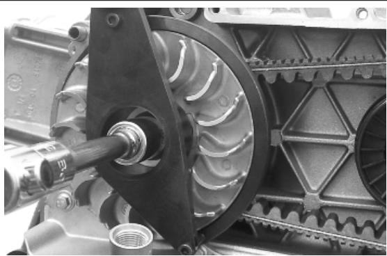
Transmission cover
- To remove the transmission cover it is necessary to remove the plastic cover first, by inserting a screwdriver in the slotted holes. Using the clutch bell lock wrench shown in the figure, remove the driven pulley shaft locking nut and washer.
020423Y driven pulley lock wrench

- Remove the transmission cover.
N.B.
WHEN YOU ARE REMOVING THE TRANSMISSION COVER YOU MUST BE CAREFUL NOT TO DROP THE CLUTCH BELL.
Air duct
- Remove the transmission compartment air intake cover shown in the photograph.
- Remove the five screws on two different levels as well as the small casing.
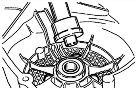
Removing the driven pulley shaft bearing
- Remove the clip from the inside of the cover.
- Remove the bearing from the crankcase by means of:
Specific tooling
020376Y Adaptor handle
020375Y Adaptor 28 × 30 ~mm
020412Y 15 mm guide
Refitting the driven pulley shaft bearing
- Slightly heat the crankcase from the inside so as not to damage the painted surface.
- Insert the bearing in its seat.
- Refit the seeger ring.
CAUTION
USE AN APPROPRIATE REST SURFACE TO AVOID DAMAGING THE COVER PAINT. N.B.
ALWAYS REPLACE THE BEARING WITH A NEW ONE UPON REFITTING.
Specific tooling
020376Y Adaptor handle
020357Y 32 x 35 mm adaptor
020412Y 15 mm guide
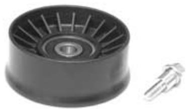
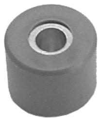
Baffle roller
Plastic roller
- Check that the roller does not show signs of wear and that it turns freely.
- Remove the special clamping screws as indicated in the photograph
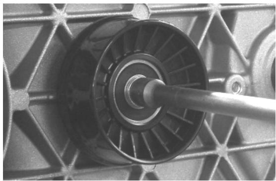
- Check the outer diameter of the roller does not have defects that could jeopardise belt functioning
- For refitting, place the roller with the belt containment edge on the engine crankcase side
- Tighten the wrench to the prescribed torque.
Locking torques (N^*m)
Anti-flapping roller 12 - 16
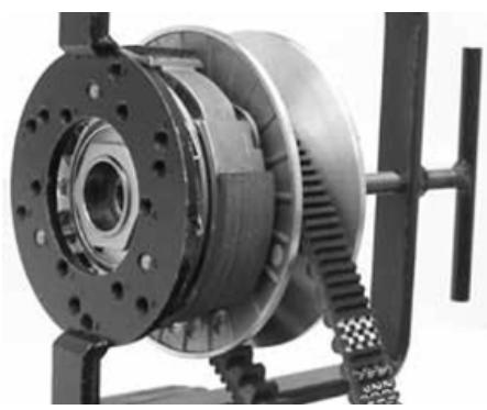
Removing the driven pulley
- Remove the clutch bell housing and the driven pulley assembly.
N.B.
THE UNIT CAN ALSO BE REMOVED WITH THE DRIVING PULLEY MOUNTED.
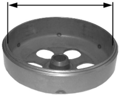
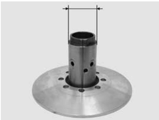
Inspecting the clutch drum
- Check that the clutch bell is not worn or damaged.
- Measure the clutch bell inside diameter.
Characteristic
Max. value clutch bell
Max. value: 0 134.5 mm
Clutch bell standard value
Standard value: 0 134 - 134.2 mm
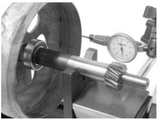
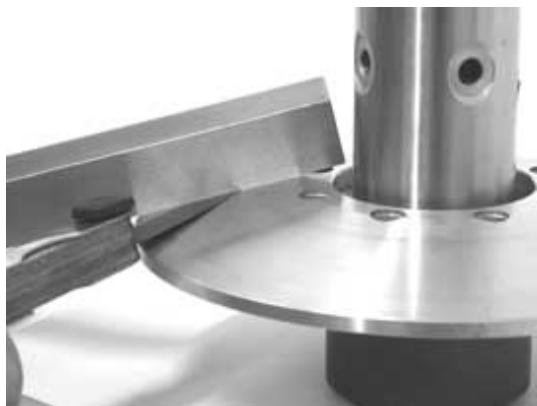
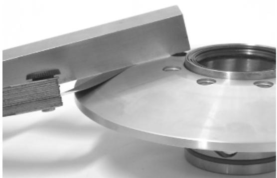
Checking the bell working surface eccentricity
- Install the bell on a driven pulley shaft using 2 bearings (inner diameter 15 and 17mm ).
- Lock with the original spacer and nut.
- Place the bell/shaft assembly on the support to check the crankshaft alignment.
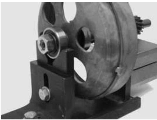
- Using a feeler pin gauge and the magnetic base, measure the bell eccentricity.
- Repeat the measurement in 3 positions (Central, internal, external).
- If faults are found, replace the bell.
020074Y Support base for checking crankshaft alignment
020335Y Magnetic support for dial gauge
Characteristic
clutch bell inspection: Limit eccentricity.
Admissible limit eccentricity: 0.15 mm
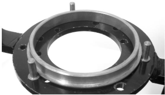
Removing the clutch
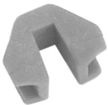
Fit the driven pulley spring compressor specific tool with medium length pins screwed in position «C» on the tool internal side.
- Introduce the adapter ring No. 11 with the cham-fering facing the inside of the tool.
- Fit the driven pulley unit on the tool with the insertion of the 3 pins in the ventilation holes in the mass holder support.
- Make sure that the clutch is perfectly inserted into the adapter ring before proceeding to loosen/tighten the clutch nut.
- Use the special 46x55 wrench component No. 9 to remove the nut fixing the clutch in place.
- Dismantle the driven pulley components (Clutch and spring with its plastic holder)
CAUTION
THE TOOL MUST BE FIRMLY FIXED IN THE CLAMP AND THE CENTRAL SCREW MUST BE BROUGHT INTO CONTACT WITH THE TOOL. EXCESSIVE TORQUE CAN CAUSE THE SPECIFIC TOOL TO BUCKLE.
020444Y011 adapter ring
020444Y009 46x55 Wrench
020444Y Tool for fitting/ removing the driven pulley clutch
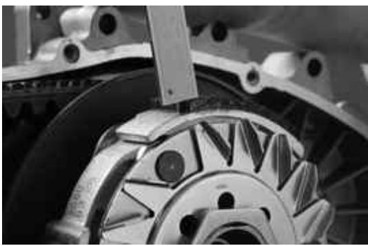
Inspecting the clutch
- Check the thickness of the clutch mass friction material.
- The masses must not show traces of lubricants; otherwise, check the driven pulley unit seals.
N.B.
UPON RUNNING-IN, THE MASSES MUST EXHIBIT A CENTRAL CONTACT SURFACE AND MUST NOT BE DIFFERENT FROM ONE ANOTHER.
VARIOUS CONDITIONS CAN CAUSE THE CLUTCH TO TEAR.
CAUTION
DO NOT OPEN THE MASSES USING TOOLS TO PREVENT A VARIATION IN THE RETURN SPRING LOAD.
Characteristic
Check minimum thickness
1 mm
Pin retaining collar
- Simultaneously turn and pull the collar manually to remove it.
N.B.
USE TWO SCREWDRIVERS IF YOU HAVE DIFFICULTY.
N.B.
BE CAREFUL NOT TO PUSH THE SCREW DRIVERS IN TOO FAR TO AVOID DAMAGE THAT COULD ENDANGER THE O-RING SEAL.
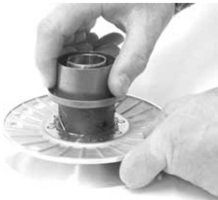
- Remove the four torque server pins and pull the pulley halves apart.
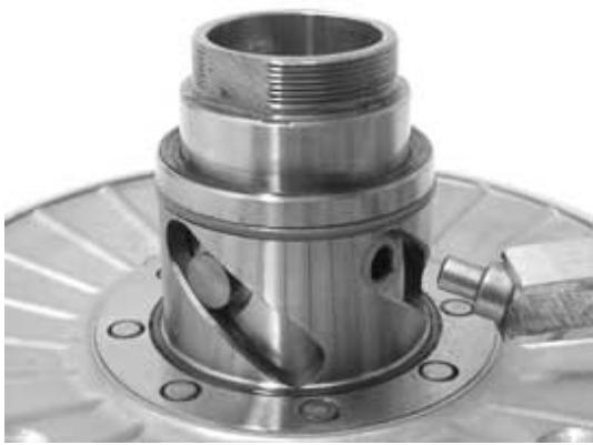
Removing the driven half-pulley bearing
- Check there are no signs of wear and/or noisiness; - Replace with a new one if there are.
- Remove the retaining ring using two flat blade screwdrivers.
- Support the pulley bushing adequately from the threaded side using a wooden surface.
- Using a hammer and pin, knock the ball bearing out as shown in the figure.
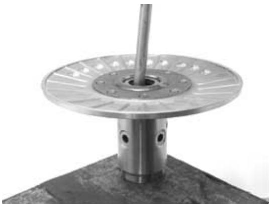
- Support the pulley properly using the bell as shown in the figure.
001467Y035 Belle for OD 47-mm bearings
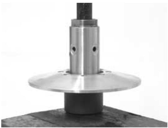
- Remove the roller bearing using the modular punch.
020376Y Adaptor handle
020456Y 0 24 mm adaptor
020363Y 20 mm guide
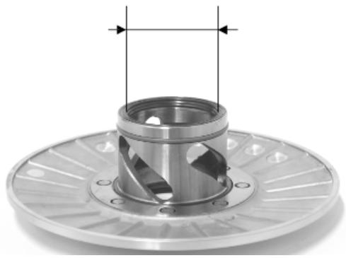
Inspecting the driven fixed half-pulley
- Measure the outer diameter of the pulley bushing.
- Check the contact surface with the belt to make sure there are no flaws.
- Check the riveted joints are functional.
- Check the evenness of the belt contact surface.
Characteristic
Half-pulley minimum diameter
Minimum admissible diameter 40.96mm
Half-pulley standard diameter
Standard diameter: 0.40985mm
Wear limit
0.3 mm
Inspecting the driven sliding half-pulley
- Remove the two internal grommets and the two O-rings.
- Measure the movable half-pulley bushing inside diameter.
- Check the contact surface with the belt to make sure there are no flaws.
- Check the riveted joints are functional.
- Check the evenness of the belt faying surface.
MOVABLE DRIVEN HALF-PULLEY DIMENSIONS
| Specification | Desc./Quantity |
| Wear limit | 0.3 mm |
| standard diameter | Diameter 41.000 - 41.035 mm |
| maximum allowable diameter | Ø 41.08 mm |
Refitting the driven half-pulley bearing
- Support the pulley bushing adequately from the threaded side using a wooden surface.
- Fit a new roller sleeve as in the figure.
- For the fitting of the new ball bearing, follow the example in the figure using a modular punch.
Fit the retention ring
WARNING
N.B.
FIT THE BALL BEARING WITH THE VISIBLE SHIELD
Specific tooling
020376Y Adaptor handle
020375Y Adaptor 28 × 30 ~mm
020424Y Driven pulley roller casing fitting punch
Refitting the driven pulley
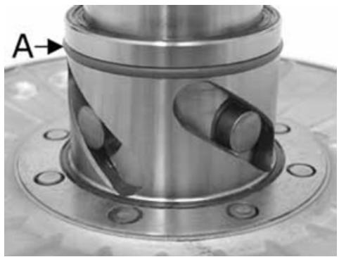
- Insert the new oil guards and O-rings on the movable half-pulley.
- Lightly grease the O-rings «A» shown in the figure.
- Fit the half-pulley over the bushing using the spe-cific tool.
- Check that the pins are not worn and proceed to refitting them in their slots.
- Refit the torque server closure collar.
- Using a curved-spout grease gun, lubricate the driven pulley unit with approximately 6 gr. of
grease. Apply the grease through one of the holes in the bushing until it comes out through the hole on the opposite side. This operation is necessary to avoid the presence of grease beyond the O-rings.
N.B.
THE TORQUE SERVER CAN BE GREASED
WHETHER WITH BEARINGS FITTED OR
WHEN THEY ARE BEING REPLACED; UNDER-
TAKING THE OPERATION WHEN THE BEAR
INGS ARE BEING SERVICED MIGHT BE EAS-
IER.
Specific tooling
020263Y Sheath for driven pulley fitting
Recommended products
AGIP GREASE SM 2 Grease for the tone wheel revolving ring
Soap-based lithium grease containing NLGI 2 Mo
lybdenum disulphide; ISO-L-XBCHB2, DIN
KF2K-20
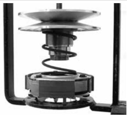
Inspecting the clutch spring
- Measure the length of the spring, while it is relaxed.
Characteristic
Standard length
123 mm
acceptable limit after use:
118 mm
Refitting the clutch
- Support the driven pulley spring compressor appropriate tool with the control screw in vertical axis.
- Arrange the tool with the medium length pins screwed in position "C" on the inside.
- Introduce the adapter ring No. 11 with the cham-fering facing upwards.
- Insert the clutch on the adapter ring.
- Lubricate the end of the spring that abuts against the servo-system closing collar.
- Insert the spring with its plastic holder in contact with the clutch.
- Insert the driving belt into the pulley unit according to their direction of rotation.
- Insert the pulley unit with the belt into the tool.
- Slightly preload the spring.
- Make sure that the clutch is perfectly inserted into the adapter ring before proceeding to tighten the clutch nut.
- Place the tool in the clamp with the control screw on the horizontal axis.
- Fully preload the spring.
- Apply the clutch fixing nut and tighten it to the prescribed torque using the special 46x55 wrench.
- Loosen the tool clamp and insert the belt according to its direction of rotation.
- Lock the driven pulley again using the specific tool.
- Preload the clutch return spring with a traction/rotation combined action and place the belt in the smaller diameter rolling position.
- Remove the driven pulley /belt unit from the tool.
N.B.
DURING THE SPRING PRELOADING PHASE, BE CAREFUL NOT TO DAMAGE THE PLASTIC SPRING STOP AND THE BUSHING THREADING.
N.B.
FOR DESIGN REASONS, THE NUT IS SLIGHTLY ASYMMETRIC; THE FLATTEST SURFACE
SHOULD BE MOUNTED IN CONTACT WITH THE CLUTCH.
Specific tooling
020444Y Tool for fitting/ removing the driven pulley clutch
020444Y011 adapter ring
020444Y009 46x55 Wrench
Locking torques (N^*m)
Clutch unit nut on driven pulley 45 ÷ 50
Refitting the driven pulley
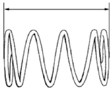
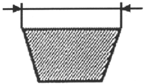
Drive-belt
- Check that the driving belt is not damaged.
- Check the width of the belt.
Characteristic
Driving belt -
Standard width: 21.3 ± 0.2 ~mm
Driving belt -
Minimum width: 19.5 mm
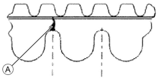
During the wear checks foreseen in the scheduled maintenance, check that the rim bottom of the toothing does not show signs of incisions or cracking (see figure); otherwise, replace the belt.
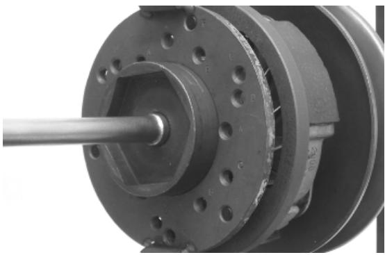
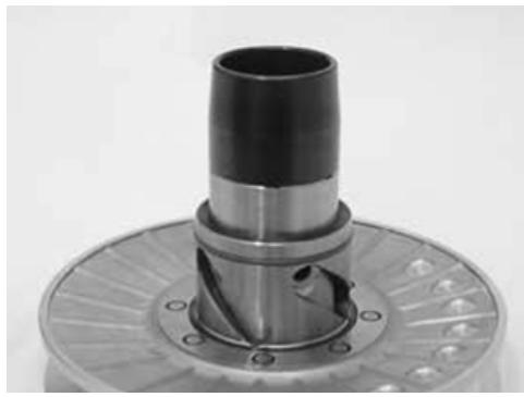
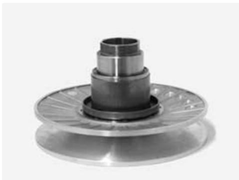
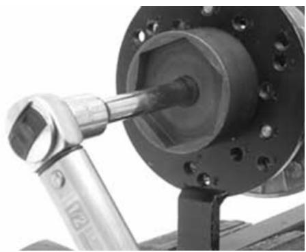
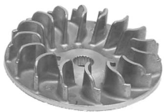
Removing the driving pulley
- Turn the crankshaft until the ropes of the pulley are on a horizontal axis
- Insert the adaptor sleeve of the appropriate tool in the hole shown in the photograph
- Insert the tool in the hollows and apply the retention ring
- Bring in the ring's clamping screws while keeping the tool to support the pulley
020626Y Driving pulley lock wrench
- Remove the fixing nut and the washer
- Remove the stationary drive pulley half.
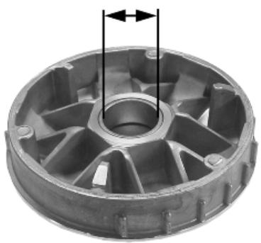
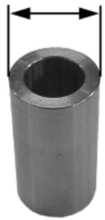
Inspecting the rollers case
- Check that the internal bushing shown in the figure is not abnormally worn and measure inner diameter A.
- Measure outer diameter B of the pulley sliding bushing shown in the figure.
- Check that the rollers are not damaged or worn.
- Check the guide shoes for the variator back-plate are not worn.
- Check the wear of the roller housings and of the belt contact surfaces on both pulley halves.
- Check that stationary driving pulley does not show signs of abnormal wear on the grooved edge and on the surface in contact with the belt.
- Check that the O-ring is not pushed out of shape.
CAUTION
DO NOT LUBRICATE OR CLEAN SINTERED BUSHINGS
Characteristic
Movable driving half-pulley bushing: Standard Diameter
26.000 - 26.021 mm
Movable driving half-pulley bushing: Maximum allowable diameter
0 26.12 mm
Sliding bushing: Standard Diameter
25.959÷25.98mm
Sliding bushing: Minimum admissible diameter
25.95 mm
Roller: Standard Diameter
Diameter 20.5 - 20.7 mm
Roller: Minimum diameter permitted
0 20 mm
Refitting the driving pulley
- Preassemble the movable half-pulley with the roller contrast plate by putting the rollers in their housings with the larger support surface touching the pulley according to the direction of rotation.
- Check that the roller contact plate does not have flaws and is not damaged on the grooved edge.
- Mount the complete bushing unit on the driving shaft.
- Fit the driven pulley/Clutch/belt unit on the engine.


- Fit the steel shim in contact with the bushing and the stationary drive pulley.
- Install the appropriate tool as described in the removal phase.
-Tighten the nut with washer to the prescribed torque.
Specific tooling
020626Y Driving pulley lock wrench
Locking torques (N^*m)
Drive pulley nut 75 ÷ 83
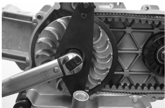
Refitting the transmission cover
- Check the presence of the 2 centring dowels and the correct installation of the sealing gasket for the oil sump on the transmission cover.
- Replace the cover tightening the 10 screws at the specified torque.
- Refit the oil loading cap/bar.
- refit the steel washer and the driven pulley nut.
- Tighten the nut to the prescribed torque using the lock wrench and the torque wrench tools.
- Replace the plastic cover.
020423Y driven pulley lock wrench
Locking torques (N^*m)
Transmission cover screws 11 ÷ 13 Driven pulley shaft nut 54 ÷ 60
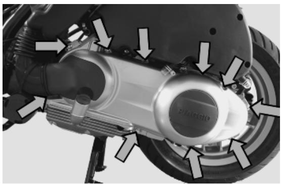
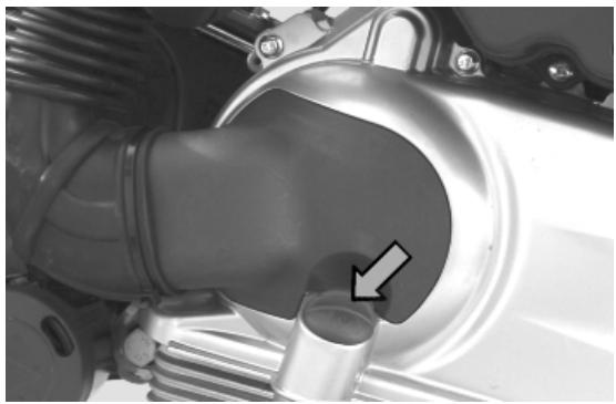
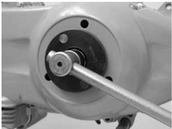
End gear
Removing the hub cover
- Empty the rear hub through the oil drainage plug.
- Remove the 7 flanged screws indicated in the figure.
- Remove the hub cover and its gasket.
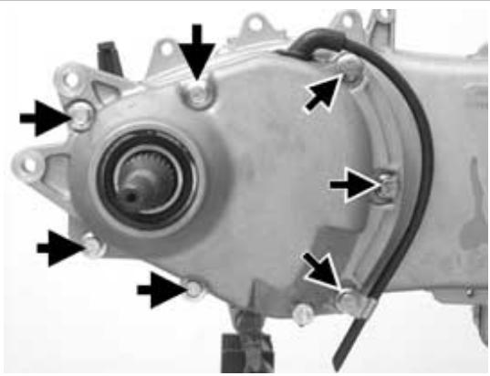
Removing the wheel axle
- Remove the wheel axis complete with gear.
- Remove the intermediate gear.
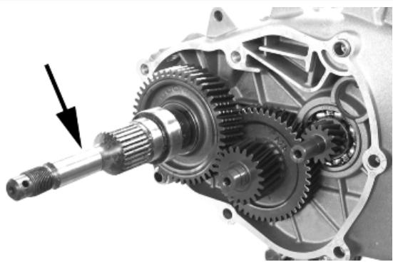

Removing the hub bearings
- Check the state of the bearings being examined (wear, clearance and noisiness). If faults are detected, do the following.
- Use the specific bearing extractor to remove the three 15 ~mm bearings (2 in the crankcase and 1 in the hub cover).
001467Y013 Pliers to extract 15-mm bearings
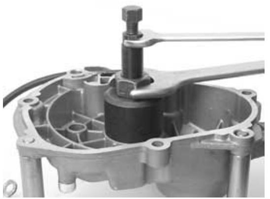
Removing the wheel axle bearings
- Take out the clip on the outside of the gearbox cover.
- Support the hub cover and expel the bearing. By means of the appropriate tools, remove the oil guard as in the figure.
020376Y Adaptor handle
020477Y Adaptor 37 mm
020483Y 30 mm guide
020359Y 42x47-mm adaptor
020489Y Hub cover support stud bolt set
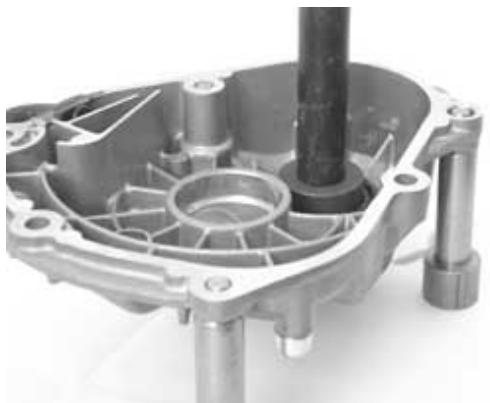
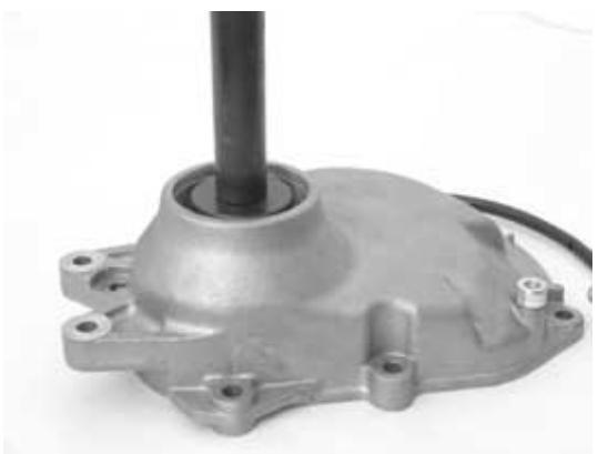
Removing the driven pulley shaft bearing
- As you need to remove the driven pulley shaft, its bearing and oil guard, remove the transmission cover as described above.
- Extract the driven pulley shaft from its bearing.
- Remove the oil guard using a screwdriver, working from inside the bearing and being careful not to damage the housing, make it come out of the belt transmission side.
- Remove the seeger ring shown in the figure
Remove the driven pulley shaft bearing using the modular punch.
020376Y Adaptor handle
020375Y Adaptor 28 x 30 mm
020363Y 20 mm guide
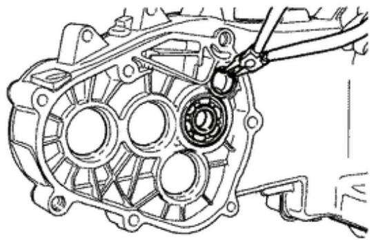
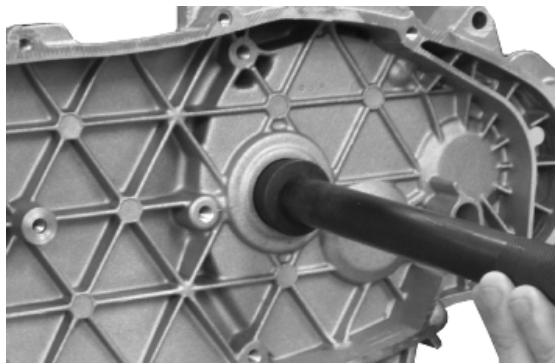
Inspecting the hub shaft
- Check the three shafts for wear or distortion of the toothed surfaces, the bearing housings, and the oil seal housings.
- In case of anomalies, replace the damaged components.
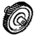
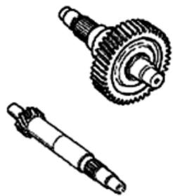
Inspecting the hub cover
- Check that the fitting surface is not dented or distorted.
- Check the bearing bearings.
- In case of anomalies, replace the damaged components.
Refitting the wheel axle bearing
- Support the hub cover on a wooden surface.
- Heat the crankcase cover with the specific heat gun.
- Fit the wheel shaft bearing with a modular punch as shown in the figure.
- Fit the seeger ring.
- Fit the oil guard with seal lip towards the inside of the hub and place it flush with the internal surface by means of the appropriate tool used from the 52 mm side.
The 52 mm side of the adapter must be turned towards the bearing.
020376Y Adaptor handle
020360Y Adaptor 52 × 55 ~mm
020483Y 30 mm guide
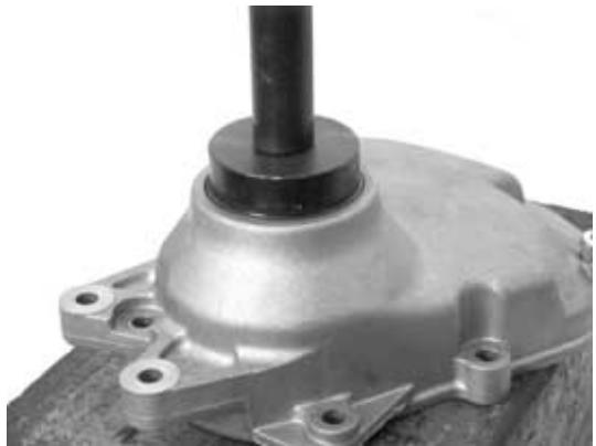
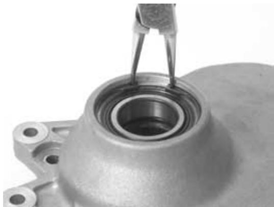
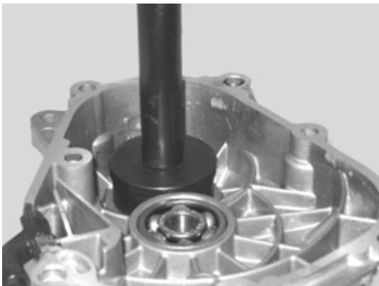
Refitting the hub cover bearings
For the fitting of the hub box bearings the engine crankcase and the cover must be heated with the special heat gun.
- The three 15mm bearings must be fitted using the appropriate tools.
- The 42-mm side of the adapter must be turned towards the bearing.
020150Y Air heater support
020151Y Air heater
020376Y Adaptor handle
020359Y 42x47-mm adaptor
020412Y 15 mm guide
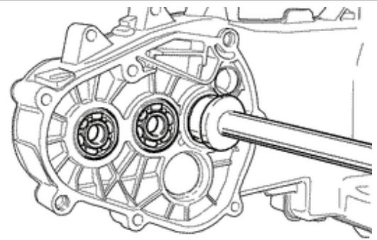
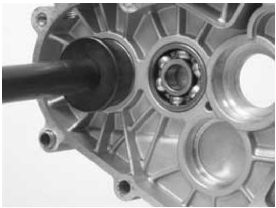
N.B.
TO FIT THE BEARING ON THE COVER, SUPPORT THE COVER WITH THE STUD BOLT SET.
- Refit the driven pulley shaft bearing with a modular punch as shown in the figure.
N.B.
IF THE BEARING HAS AN ASYMMETRICAL BALL RETainer, PLACE IT SO THAT THE BALLS ARE VISIBLE FROM THE HUB INNER SIDE.
020376Y Adaptor handle
020359Y 42x47-mm adaptor
020363Y 20 mm guide
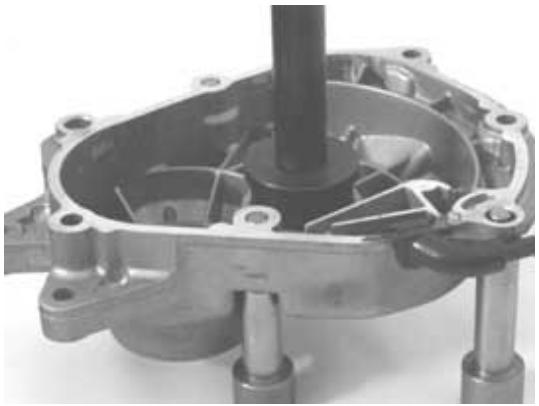
N.B.
WHEN FITTING THE BEARINGS ON THE ENGINE CRANKCASE, SUPPORT THE CRANKCASE PREFERABLY ON A SURFACE TO ALLOW THE BEARINGS TO BE DRIVEN VERTICALLY.
- Refit the seeger ring with the opening facing the bearing and fit a new oil guard flush with the crankcase from the pulley side.
Refitting the hub bearings
- Install the three shafts in the engine crankcase as shown in the figure.
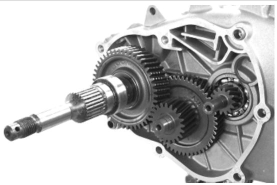
Refitting the ub cover
- Fit a new gasket together with the centring dowels.
- Seal the gasket of the breather pipe using black silicone sealant.
- Fit the gearbox cover, making sure the breather pipe is in the correct position.
- Position the shorter screw that can also be recognised from the different colour as shown in the figure.
- Fix the breather tube support by means of the lower screw.
- Fit the remaining screws and tighten the seven screws to the prescribed torque.
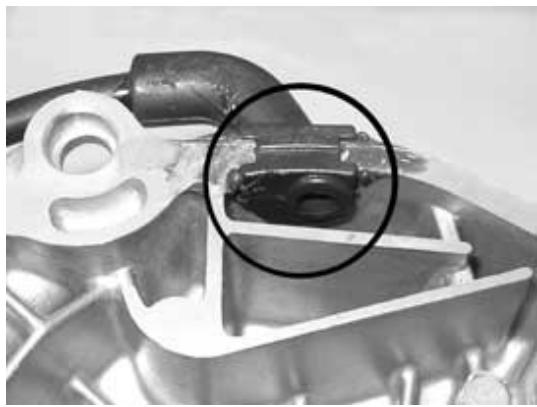
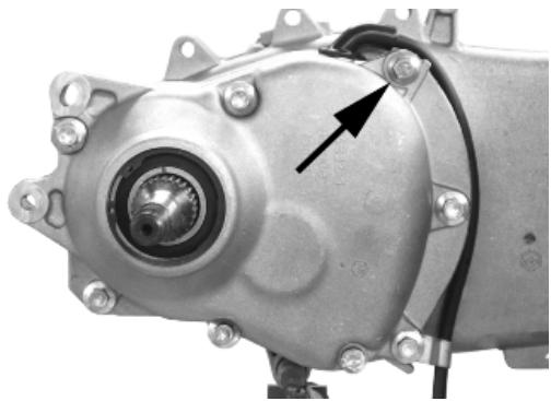
Flywheel cover
Removing the hub cover
- Remove the clamp fixing the sleeve to the cylinder and detach the sleeve.
- Remove the 10 fixings
- Remove the flywheel cover.
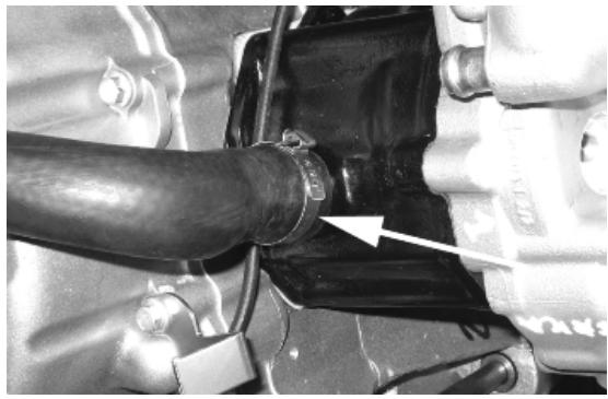
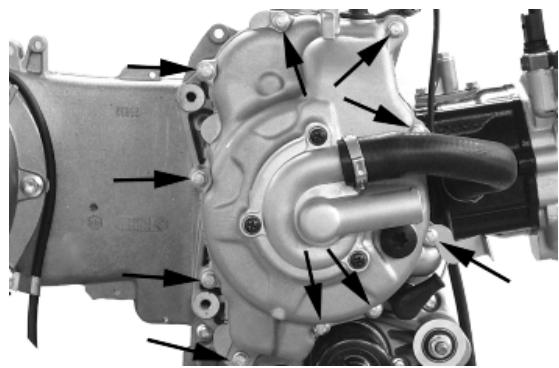
Removing the stator
- Remove the two pickup screws and the screw holding the wiring support and the three stator clamping screws shown in the figure.
- Remove the stator and its wiring.

Refitting the stator
- Refit the stator and flywheel carrying out the removal procedure in reverse, tightening the retainers to the specified torque.
Locking torques (N^*m)
Stator assembly screws (^) 3 ÷ 4
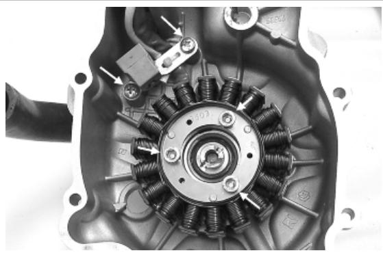
Refitting the flywheel cover
- Position the spline clip on the crankshaft and orient the end as shown in the figure.
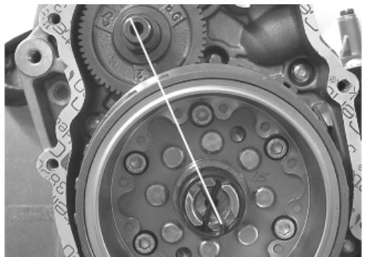
- Orient the water pump shaft with reference to the transmission gear seat as shown in the photo.
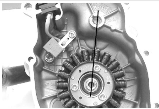
- Refit the cover over the engine and tighten the screws to the prescribed torque.
- Carry out the steps in the reverse order from the dismantling procedure.
CAUTION
TAKE CARE TO CORRECTLY POSITION THE FLYWHEEL CONNECTOR. MAKE SURE THE CENTRING DOWELS ARE PRESENT.
Locking torques (N^*m)
Flywheel cover screws 11 - 13
Flywheel and starting
Removing the starter motor
- Remove the two screws indicated in the figure.
- Take the starter motor out of its seat

Removing the flywheel magneto
- Remove the water pump shaft and crankshaft spline clip
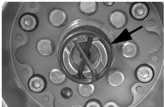
- Line up the two holes in the flywheel as shown in the photo
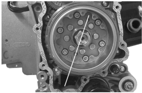
- Screw in the guide bushing that is part of the special flywheel stop tool on the flywheel as shown in the photo.
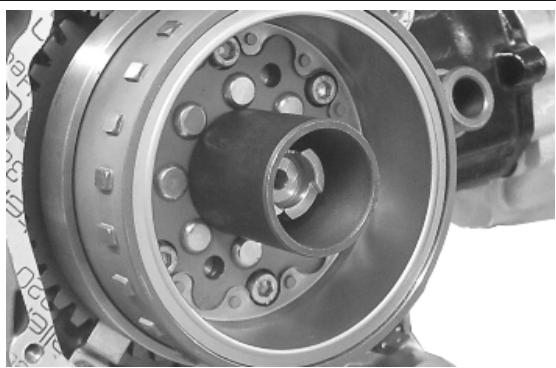
- Insert the special flywheel stop tool on the fly-wheel as shown in the photo
Specific tooling
020627Y Flywheel lock wrench
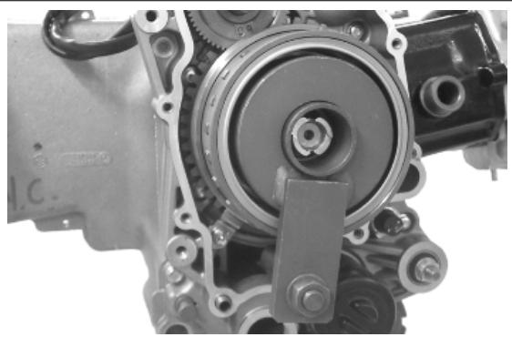
- Remove the plate indicated in the photo.
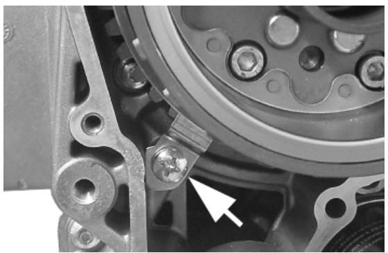
- Remove the flywheel nut with its washer
- Do up the flywheel nut by three or four threads so that the flywheel does not fall accidentally on extraction
- Screw the extractor onto the flywheel and extract it as shown in the photograph
Specific tooling
020467Y Flywheel extractor
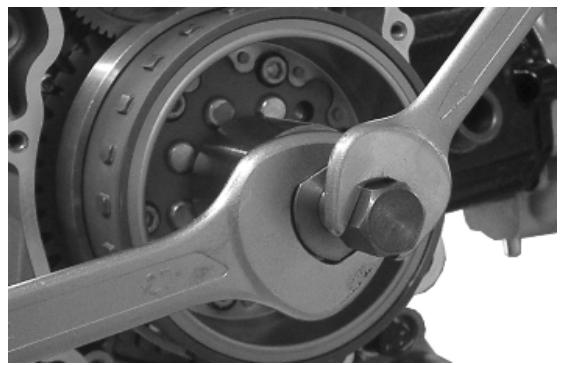
Inspecting the flywheel components
- Check the integrity of the internal plastic parts of the flywheel and the Pick-Up control plate.
Refitting the free wheel
- Make sure the free wheel contact surfaces are in good condition.
- Thoroughly clean the free wheel to remove LOCTITE residue.
- Degrease the threading of the holes in the free wheel and the clamping screws.
- Apply the recommended product to the end of the screws.
Recommended products
Loctite 243 Medium strength threadlock
Loctite 243 medium-strength threadlock
- Fit the freewheel on the magneto flywheel making sure that the ground side is in contact with the flywheel itself, i.e. with wheel seeger ring visible.
- Lock the six clamping screws in criss-cross fashion to the prescribed torque.
Locking torques (N^*m)
Screw fixing freewheel to flywheel 13 ÷ 15
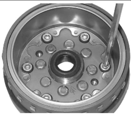
- Oil the free wheel "rollers".
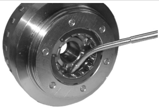
Refitting the flywheel magneto
- Remove the freewheel retaining plate indicated in the photograph
- Remove the transmission gear and the freewheel
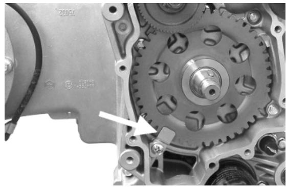
- Insert the free wheel on the flywheel as shown in the photo
- Then refit the flywheel with free wheel and transmission gear
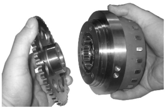
- Using the special flywheel stop tool, tighten up the flywheel fixing nut to the prescribed torque
-Refit the retention plate
Specific tooling
020627Y Flywheel lock wrench
Locking torques (N^*m)
Flywheel nut 94 ÷ 102

Refitting the starter motor
- Fit a new O-ring on the starter motor and lubricate it.
- Fit the starter on the crankcase, locking the two screws to the prescribed torque.
Locking torques (N^*m)
Starter motor screws 11 ÷ 13
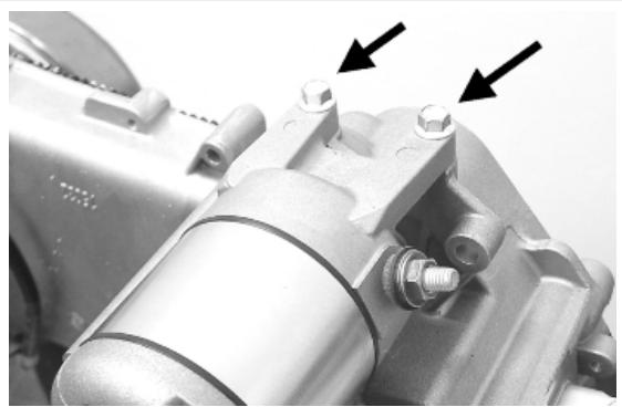
Cylinder assay. and timing system
Removing the intake manifold
Loosen the three screws and remove the air intake manifold.
- When refitting, secure to the specified torque.
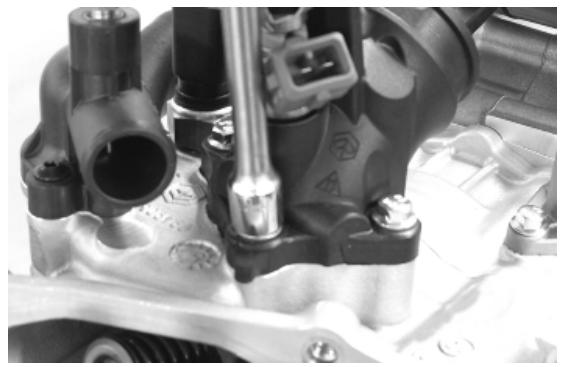
Removing the rocker-arms cover
- Remove the 5 screws indicated in the figure
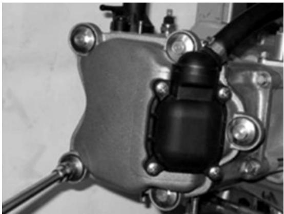
Removing the timing system drive
- Remove the parts listed below first: transmission cover, drive pulley with belt, oil sump with spring and by-pass piston, oil pump pulley cover, O-ring on the crankshaft and the sprocket wheel separation washer.
- Remove the tappet cover.
- Remove the central screw fastener and the automatic valve-lifter retaining cover, as shown in the figure.
- Remove the return spring of the automatic valve lifter unit and the automatic valve lifter unit and its end of stroke washer.
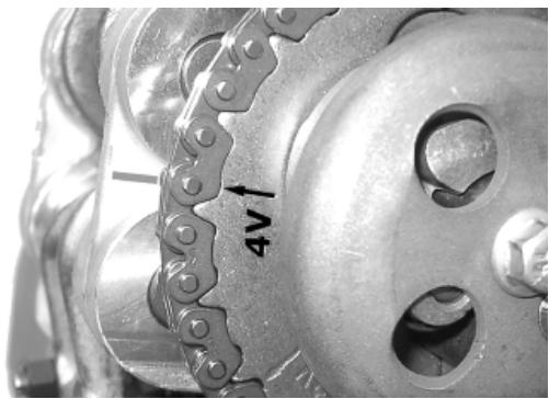
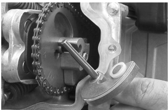
- Loosen the central screw on the tensioner first.
- Remove the two fixings shown in the figure.
- Remove the tensioner with its gasket.
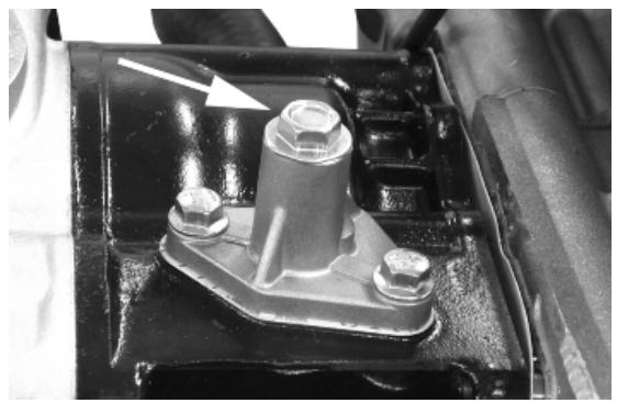
- Remove the internal hex screw and the counterweight shown in the figure.
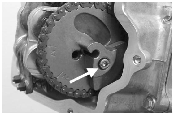
- Remove the camshaft control pulley with its washer.
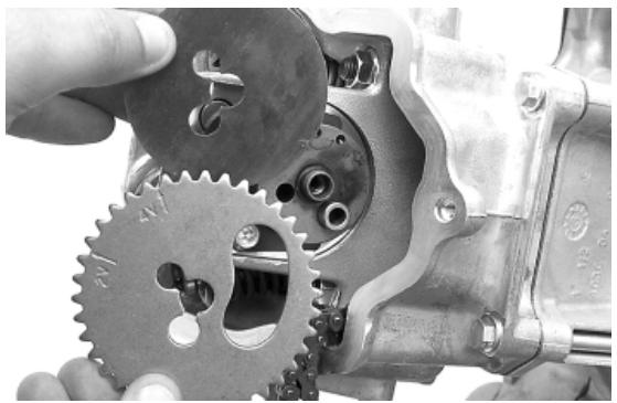
- Remove the command sprocket wheel and the timing chain.
- Remove the screws indicated in the figure, the spacer bar and the tensioner slider.
The chain tensioning pad must be removed from the transmission side. As regards the lower chain guide pad, it may only be removed after the head has been removed.
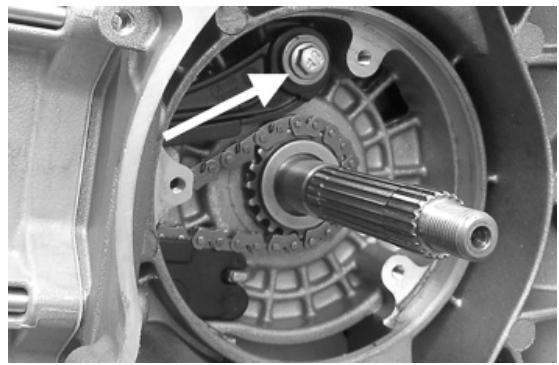
N.B.
IT IS ADVISIBLE TO MARK THE CHAIN IN ORDER TO ENSURE THAT THE INITIAL DIRECTION OF ROTATION IS MAINTAINED.
Removing the cam shaft
- Remove the two screws and the cam shaft retainer shown in the diagram.
- Remove the pins and the rocker arms from the flywheel side holes.
- Remove the cam shaft.
N.B.
IN CASE OF NEED, THE HEAD MAY BE REMOVED WITH THE CAMSHAFT, PINS, ROCKING LEVERS AND FIXING BRACKET. THE HEAD CAN ALSO BE REMOVED WITHOUT REMOving THE CHAIN AND THE DRIVING SHAFT CHAIN TIGHTENER.
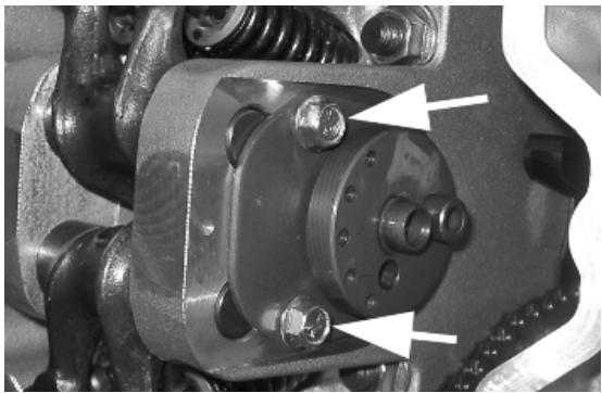
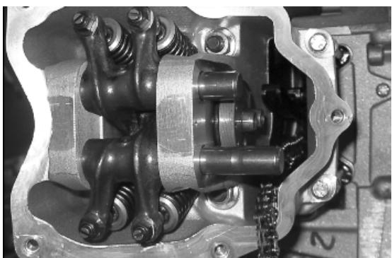
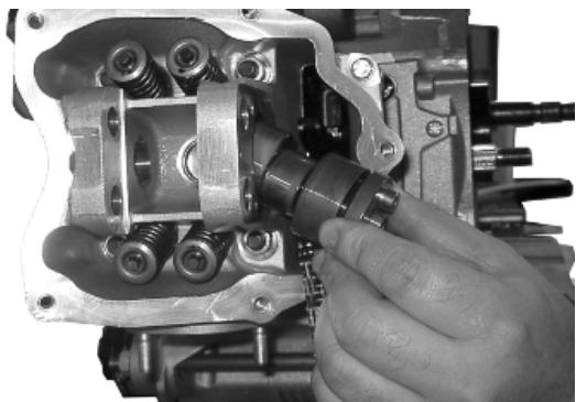
Removing the cylinder head
- Remove the spark plug.
- Remove the 2 side fixings shown in the figure.
- Loosen the 4 head-cylinder fastening nuts in two or three stages and in criss-cross fashion.
- Remove the head, the two centring dowels and the gasket.
N.B.
IN CASE OF NEED, THE HEAD MAY BE REMOVED WITH THE CAMSHAFT, PINS, ROCKING LEVERS AND FIXING BRACKET. THE HEAD CAN ALSO BE REMOVED WITHOUT RE
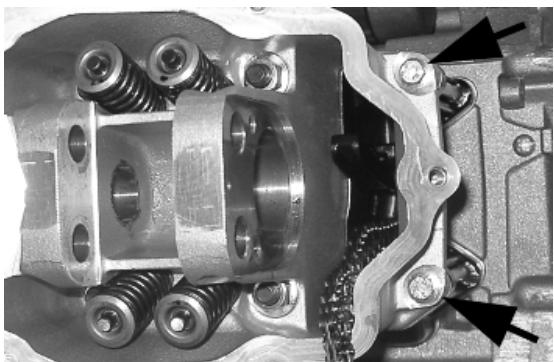
MOVING THE CHAIN AND THE DRIVING SHAFT CHAIN TIGHTENER.
Removing the valves
- Using the appropriate tool fitted with an adaptor, remove the cotters, caps, springs and valves.
- Remove the oil guards with the appropriate tool.
- Remove the lower spring supports.
CAUTION
REPLACE THE VALVES IN SUCH A WAY AS TO RECOGNISE THEIR ORIGINAL POSITION ON THE HEAD.
020382Y011 adapter for valve removal tool
020382Y Valve coters equipped with part 012 removal tool
020431Y Valve oil seal extractor
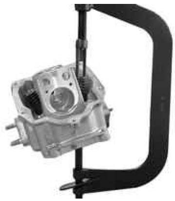
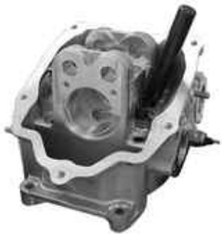
Removing the cylinder - piston assay.
Removing cylinder and piston
- Remove the chain guide pad.
- Remove the 4 O-rings on the stud bolts.
- Pull out the cylinder.
- Remove the cylinder base gasket.
- Remove the two stop rings, the wrist pin and the piston.
- Remove the piston seals.
CAUTION
TO AVOID DAMAGING THE PISTON, SUPPORT IT WHILE REMOVIDING THE CYLINDER. N.B.
BE CAREFUL NOT TO DAMAGE THE SEALING RINGS DURING REMOVAL.
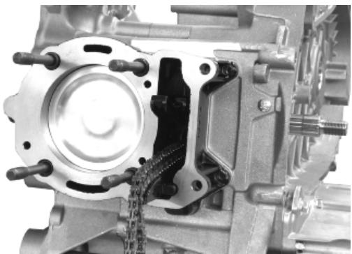
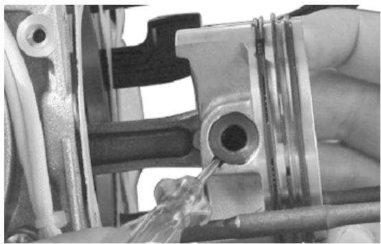
Inspecting the small end
- Measure the internal diameter of the small end using an internal micrometer.
N.B.
REPLACE THE CRANKSHAFT IF THE DIAMETER OF THE ROD SMALL END EXCEEDS THE STANDARD DIAMETER OR IT SHOWS SIGNS OF WEAR OR OVERHEATING.
Characteristic
Checking the connecting rod small end: Maximum diameter
15.030 mm
Checking the connecting rod small end: Standard diameter
15 +0.015+0.025 mm
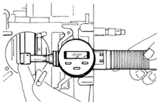
Inspecting the wrist pin
- Measure the outer diameter of the gudgeon pin.
- Calculate the coupling clearance between pin and connecting rod end.
Characteristic
Pin diameter: Standard clearance
0.015 ÷ 0.029 ~mm
Pin diameter Standard diameter
14.996 - 15.000 mm
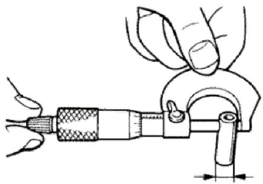
Inspecting the piston
- Measure the diameter of the wrist pin seat on the piston.
- Calculate the piston pin coupling clearance.
- Measure the outside diameter of the piston, perpendicular to the gudgeon pin axis.
- Take the measurement at 5mm from the base in the position shown in the figure.
- Carefully clean the seal housings.
- Measure the coupling clearance between the seal rings and the grooves using suitable sensors, as shown in the diagram.
- If the clearance is greater than that indicated in the table, replace the piston.
N.B.
MEASURE THE CLEARANCE BY INSERTING THE BLADE OF THE FEELER GAUGE FROM THE SECOND SEAL SIDE.
N.B.
THE PIN HOUSINGS HAVE 2 LUBRICATION CHANNELS. FOR THIS REASON MEASUREMENT OF THE DIAMETER MUST BE CARRIED OUT ACCORDING TO THE AXIS OF THE PISTON.
Characteristic
Wrist pin seat on the piston: Standard diameter
15.001 ÷ 15.006 ~mm
Diameter of the wrist pin seat on the piston: Standard clearance
0.001 ÷ 0.010 ~mm
piston diameter
71.953 - 71.981 mm
Fitting clearance
Top piston ring - standard coupling clearance 0.015 - 0.06 mm Top piston ring - maximum clearance allowed after use 0.07 mm Middle piston ring - standard coupling clearance 0.015 - 0.06 mm Middle piston ring - maximum clearance allowed after use 0.07 mm oil scraper ring - standard coupling clearance 0.015 - 0.06 mm oil scraper ring - maximum clearance allowed after use 0.07 mm
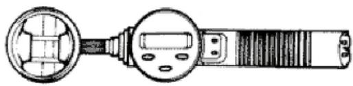
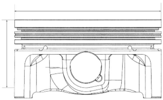
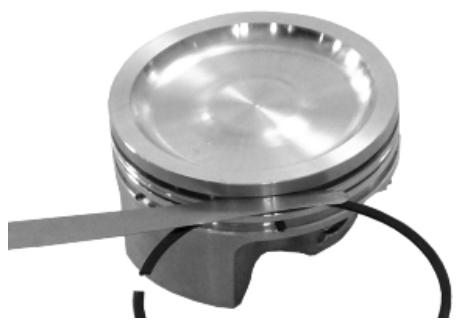
Inspecting the cylinder
- Using a bore meter, measure the inner cylinder diameter at three different points according to the directions shown in the figure.
- Check that the head coupling surface is not worn or misshapen.
- Pistons and cylinders are classified according to diameter. The coupling must be made with those of the same type (M-M, N-N, O-O, P-P).
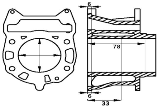
Characteristic
cylinder: standard diameter
71.990 - 72.018 mm (at 33 mm)
Maximum allowable run-out:
0.05 mm
Inspecting the piston rings
Sealing rings
- Alternately insert the three sealing rings into the cylinder, in the area where it retains its original diameter. Using the piston, insert the rings perpendicularly to the cylinder axis.
- Measure the opening (see figure) of the sealing rings using a feeler gauge.
- If any measurements are greater than specified, replace the piston rings.
N.B.
BEFORE REPLACING ONLY THE PISTON RINGS, ENSURE THAT THE CLEARANCE BETWEEN THE PISTON RINGS AND THE PISTON RING GROOVES, AND BETWEEN THE PISTON AND THE CYLINDER, IS AS SPECIFIED. IN ANY CASE, NEW PISTON RINGS USED IN COMBINATION WITH A USED CYLINDER MAY HAVE DIFFERENT BEDDING CONDITIONS THAN THE STANDARD.
Characteristic
Top piston ring
Standard opening: 0.15 ÷ 0.30 ~mm
Middle piston ring
Standard opening: 0.20 ÷ 0.40 ~mm
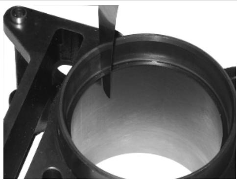
scaper ring
Standard opening: 0.20 ÷ 0.40 ~mm
Removing the piston
- Install piston and wrist pin onto the connecting rod, aligning the piston arrow the arrow facing towards the exhaust.
- Fit the wrist pin stop ring onto the appropriate tool
- With opening in the position indicated on the tool S = left
D= right
- Place the wrist pin stop ring into position using a punch
- Fit the wrist pin stop using the plug as shown in the figure
N.B.
THE TOOL FOR INSTALLING THE STOP RINGS MUST BE USED MANUALLY.
CAUTION
USING A HAMMER MIGHT DAMAGE THE STOPS' HOUSING.
Specific tooling
020454Y Tool for fitting piston pin stops (200 - 250)
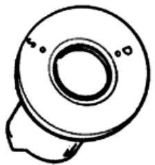
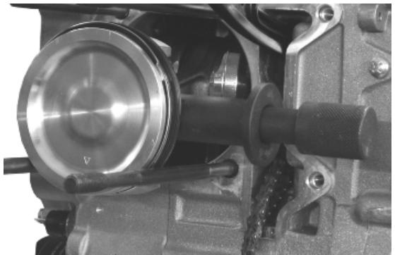
Choosing the gasket
Characteristic
Compression ratio
11± 0.5:1
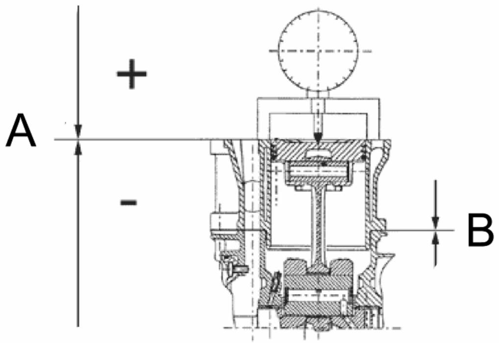
Measurement «A» to be taken, is a value of piston re-entry. It indicates by how much the plane formed by the piston crown descends below the plane formed by the upper part of the cylinder. The further the piston travels into the cylinder, the thinner the thickness «B» of the base gasket to be applied (to obtain the required compression ratio) and vice versa.
N.B.
MEASUREMENT «A» MUST BE TAKEN WITH NO GASKET FITTED BETWEEN THE CRANKCASE AND CYLINDER AND AFTER RESETTING THE GAUGE, EQUIPPED WITH A SUPPORT, ON A GROUND PLANE.
SHIMMING
| Name | Measure A | Thickness |
| shimming | 3.70 - 3.60 | 0.4 ± 0.05 |
| shimming | 3.60 - 3.40 | 0.6 ± 0.05 |
| shimming | 3.40 - 3.30 | 0.8 ± 0.05 |
Refitting the piston rings
Fitting the sealing rings
- Place the oil scraper spring on the piston.
- Refit the oil scraper ring with the join of spring ends on the opposite side from the ring gap and the word 'TOP' towards the crown of the piston. The champered side of the oil scraper ring should always be facing the piston crown.
- Fit the middle piston ring with the identification letter facing the crown of the piston. In any case, the step must be facing opposite the piston top.
- Fit the top piston ring with the word 'TOP' or the reference mark facing the crown of the piston.
- Offset the piston ring gaps on the three rings by 120^ to each other as shown in the figure.
- Lubricate the components with engine oil.
- The top piston ring on the engine has an L-shaped cross-section.
N.B.
THE TWO PISTON RINGS ARE MADE WITH A TAPERED CYLINDRICAL CONTACT CROSSSECTION. THIS IS TO ACHIEVE A BETTER BEDDING.
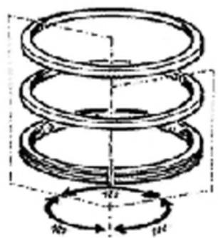
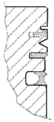
Refitting the cylinder
- Insert the cylinder base gasket with the thickness determined above.
- Using the fork support and the piston ring retaining band, refit the cylinder as shown in the figure.
N.B.
BEFORE FITTING THE CYLINDER, CAREFULLY BLOW OUT THE LUBRICATION DUCT AND OIL THE CYLINDER BARREL.
Specific tooling
020426Y Piston fitting fork
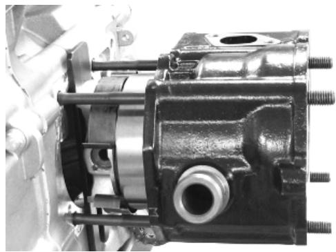
020393Y Piston fitting band
Inspecting the cylinder head
- Using a trued bar and feeler gauge check that the cylinder head surface is not worn or distorted.
Maximum allowable run-out: 0.05mm
- Check that the camshaft and the rocker pin capacities exhibit no wear.
- Check that the cylinder head cover surface, the intake manifold and the exhaust manifold are not worn.
Characteristic
bearing «A»
0 12.000 - 12.018 mm
bearing «B»
0 20.000 ÷ 20.021 mm
bearing «C»
0 37.000 - 37.025 mm
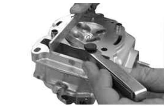
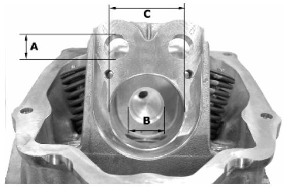
Inspecting the timing system components
- Check that the guide shoe and the tensioner shoe are not worn out.
- Ensure that the camshaft control pulley chain assembly and the sprocket wheel are not worn.
- If you encounter wear, replace the parts or, if the chain, sprocket wheel and pulley are worn replace the whole assembly.
- Remove the centre screw with the washer and the tensioner spring. Check that the one-way mechanism is not worn.
- Check the condition of the tensioner spring.
- If examples of wear are found, replace the whole assembly.
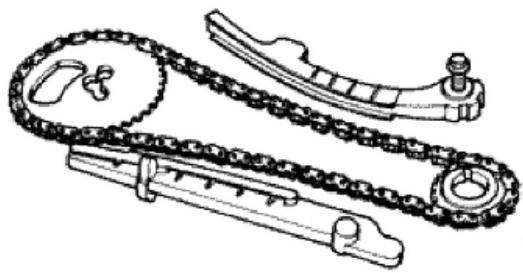
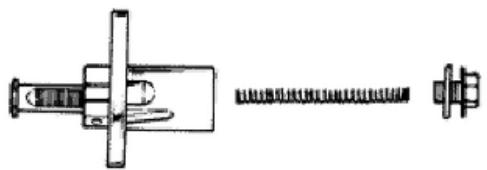
Inspecting the valve sealings
- Insert the valves into the cylinder head.
- Alternatively check the intake and exhaust valves.
- The test is carried out by filling the manifold with petrol and checking that the head does not ooze through the valves when these are just pressed with the fingers.
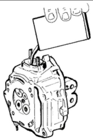
Inspecting the valve housings
- Check the width of the imprint on the valve seat «V» wear limit max. 1.6 mm.
- Remove any carbon formation from the valve guides.
- Measure the inside diameter of each valve guide.
- Take the measurement at three different heights in the rocker arm push direction.
- If the width of the impression on the valve seat or the diameter of the valve guide exceed the specified limits, replace the cylinder head.
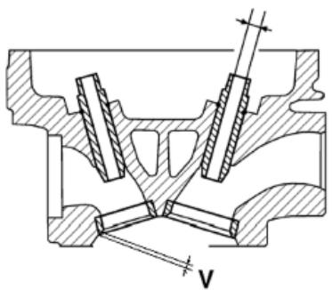
Characteristic
Valve seat wear Intake guide
limit accepted: 5.022
Valve seat wear Intake guide
Standard diameter: 5.000 ÷ 5.012 ~mm
Valve seat wear Exhaust guide
Accepted limit 5.022
Valve seat wear Exhaust guide
Standard diameter: 5.000 ÷ 5.012 ~mm
Inspecting the valves
- Measure the width of the sealing surface on the valve seats and on the valves.
Characteristic
Sealing surface length: after use:
Intake and exhaust: 1.6mm
- If any of the sealing surfaces on the valves is wider than the specified limit or is damaged in one or more points, or curved, replace the valve with a new one.
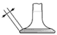
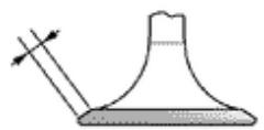
CAUTION
DO NOT REVERSE THE FITTING POSITIONS OF THE VALVES (RIGHT - LEFT).
Characteristic
Valve wear check Standard: Intake and exhaust:
0.99 - 1.27 mm
- Measure the diameter of the valve stems in the three positions indicated in the diagram.
- Calculate the clearance between valve and valve guide.
- Check that there are no signs of wear on the surface of contact with the articulated register terminal.
- If the checks above give no failures, you can use the same valves. For best sealing results, it is advisable to grind the valves. Grind the valves gently with a fine-grained lapping compound. During the grinding, keep the cylinder head with the valve axes in a horizontal position. This will prevent the lapping compound residues from penetrating between the valve stem and the guide (see figure).
CAUTION
TO AVOID SCORING THE FAYING SURFACE, DO NOT KEEP ROTATING THE VALVE WHEN NO LAPPING COMPOUND IS LEFT. CAREFULLY WASH THE CYLINDER HEAD AND THE VALVES WITH A SUITABLE PRODUCT FOR THE TYPE OF LAPPING COMPOUND BEING USED.
N.B.
DO NOT CHANGE THE POSITIONS THE VALVES ARE FITTED IN
Characteristic
Valve check standard length
Outlet: 94.4 mm
Valve check standard length
Inlet: 94.6 mm
Valve check Maximum admissible clearance
Outlet: 0.072mm
Valve check Maximum admissible clearance
Inlet: 0.062 mm
Valve check standard clearance
Outlet: 0.025 ÷ 0.052 ~mm
Valve check standard clearance
Inlet: 0.013 ÷ 0.040 mm
Valve check Minimum admissible diameter
Outlet: 4.95 mm
Valve check Minimum admissible diameter
Inlet: 4.96 mm
Valve check Standard diameter:
Inlet: 4.972 ÷ 4.987 ~mm
Valve check Standard diameter:
Outlet: 4.96 ÷ 4.975 ~mm
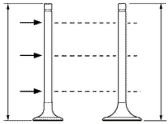
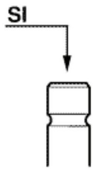
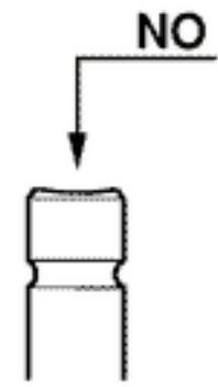
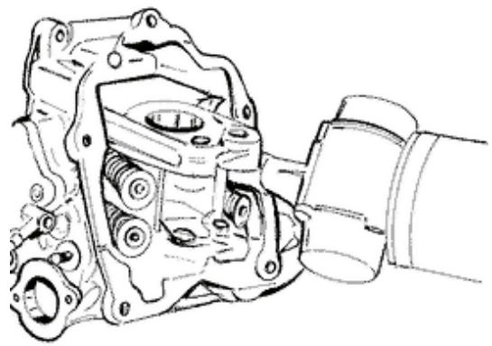
Inspecting the springs and half-cones
- Check that the upper and lower supporting washers of the springs, the cotters and the oil seal do not show signs of abnormal wear.
- Replace the components when worn.
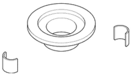
Refitting the valves
- Lubricate the valve guides with engine oil.
- Place the valve spring supports on the head.
- Using the special punch, fit the four valve seals.
- Fit the valves, the springs and the caps. Using the appropriate tool with adapter, compress the springs and insert the cotters in their seats.
N.B.
DO NOT CHANGE THE VALVE FITTING POSITION. FIT THE VALVE SPRINGS WITH THE REFERENCE COLOUR ON COTTER SIDE (TURNS WITH GREATER PITCH).
Specific tooling
020306Y Punch for assembling valve seal rings
020382Y Valve coters equipped with part 012 removal tool
020382Y011 adapter for valve removal tool
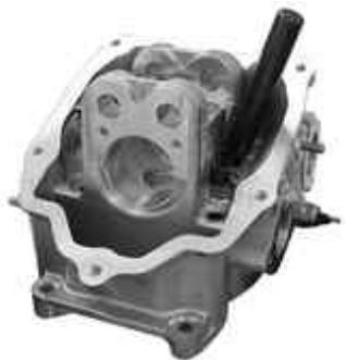
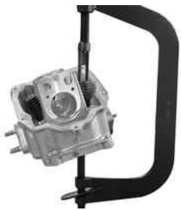
Inspecting the cam shaft
- Inspect the cam shaft for signs of abnormal wear on the caps.
- Check the cam height.
- Check there is no wear on the cam shaft retaining plate and its associated groove on the cam shaft.
- If any of the above dimensions are outside the specified limits, or there are signs of excessive
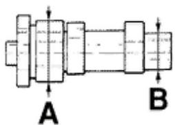
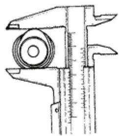
wear, replace the defective components with new ones.
-
Check there are no signs of wear on the automatic valve-lifter cam, or the end-of stroke roller, or the rubber buffer on the automatic valve-lifter retaining cover.
-
Check that the valve lifting spring has not yielded.
- Replace any defective or worn components.
- Check the rocker pins do not show signs of wear or scoring.
- Measure the internal diameter of each rocker arm.
Check there are no signs of wear on the pad from contact with the cam and on the jointed adjustment plate.
Characteristic
Internal rocker arm diameter: Standard diameter
Diameter 12.000 - 12.011 mm
Rocker arm pin diameter: Standard diameter
Diameter 11.977 - 11.985 mm
Cam shaft check: Maximum admissible axial clearance
0.42 mm
Cam shaft check: Standard axial clearance:
0.11 - 0.41 mm
Cam shaft check: Standard height
Outlet: 29.209 mm
Cam shaft check: Standard height
Inlet: 30.285 mm
Cam shaft check: Minimum admissible diameter
Bearing B diameter: 19.950 mm
Cam shaft check: Minimum admissible diameter
Bearing A Ø: 36.94 mm
Cam shaft check: Standard diameter
Bearing B diameter: 19.959 ÷ 19.98 ~mm
Cam shaft check: Standard diameter
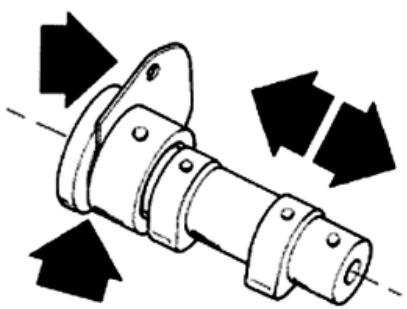
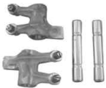
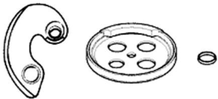
Bearing A : 36.95÷ 36.975mm
Refitting the head and timing system components
- Fit the timing chain guide pad.
- Insert the centring dowel between the cylinder head to the cylinder, fit the cylinder head gasket and the cylinder head.
- Lubricate the stud bolt threading.
- Tighten up the nuts to an initial pre-torque of 7 ± 1 N·m
- Tighten up the nuts to a second pre-torque of 10 ±1 N·m
- Rotate by an angle of 270^
- To carry out the operations described above, follow the tightening sequence in the figure.
- Fit the two screws on the outside of the timing chain side and tighten them to the specified torque.
N.B.
BEFORE INSTALLING THE HEAD, MAKE SURE THAT THE LUBRICATION CHANNEL IS CLEAN USING A COMPRESSED AIR JET.
Locking torques (N^*m)
Timing chain tensioner support screw 11 ÷ 13
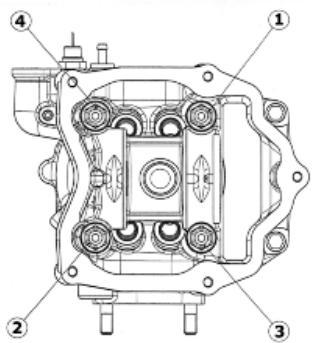
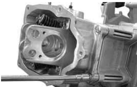
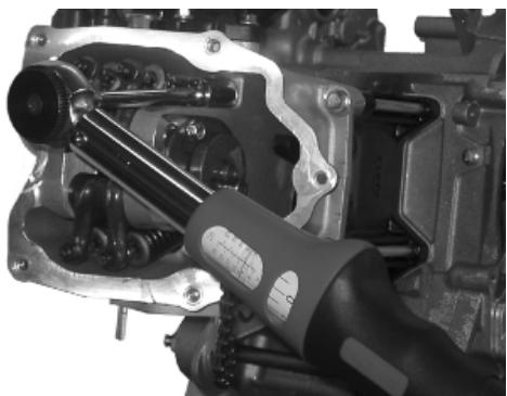
- Refit the lower timing chain sprocket wheel on the crankshaft, with the chamfer facing the insertion side.
- Loop the timing chain around the sprocket on the crankshaft.
- Fit the chain tensioner slider from the cylinder head side.
- Fit the spacer and the screw fastener.
- Tighten the screws to the prescribed torque.
- Fit the pins and rocker arms.
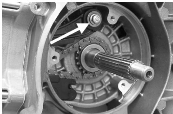
- Lubricate the two rocking levers through the holes at the top.
- Lubricate the 2 bearings and insert the cam shaft in the cylinder head with the cams corresponding to the rockers.
- Insert the retention plate and tighten the two screws shown in the figure to the prescribed torque.
- Refit the spacer on the cam shaft.
- Rotate the engine so that the piston is at top dead centre, using the reference marks on the flywheel and the crankcase.
- Holding this position insert the chain on the camshaft control pulley.
- Insert the pulley on the cam shaft while keeping the reference 4V in correspondence with the reference mark on the head.
- Fit the counterweight and tighten the fixing screw to the prescribed torque.
-Fit the end-stop ring on the automatic valve-lifter cam and fit the automatic valve-lifter cam to the cam shaft.
- Fit the automatic valve-lifter return spring.
- During this operation the spring must be loaded by approximately 180^ .
- Fit the automatic valve-lifter retaining dish, using the counterweight screw fastener as a reference.
- Tighten the clamping screw to the prescribed torque.
- Set the tensioner cursor in the rest position.
- Fit the chain tensioner on the cylinder, using a new gasket, and tight the two screws to the prescribed torque.
- Insert the chain tensioning screw, together with the spring and washer, tightening it to the prescribed torque.
- Adjust the valve clearance.
- Fit the spark plug.
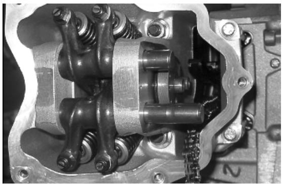
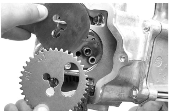
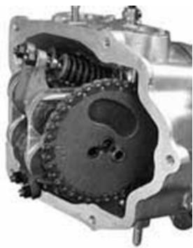
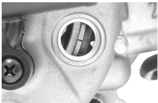
Electrode distance 0.8mm
N.B.
GREASE THE END STOP RING TO PREVENT IT COMING OUT AND FALLING INTO THE ENGINE.
Locking torques (N^*m)
Timing chain tensioner support screw 11 ÷ 13 Spark plug 12 ÷ 14 Starter ground screw 7 ÷ 8.5 Timing chain tensioner slider screw 10 ÷ 14 Starter ground support screw 11 ÷ 15 Timingchain tensioner central screw 5 - 6 Camshaftretention plate screw 4 ÷ 6
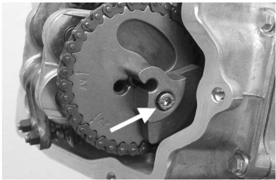
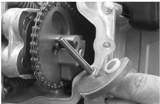
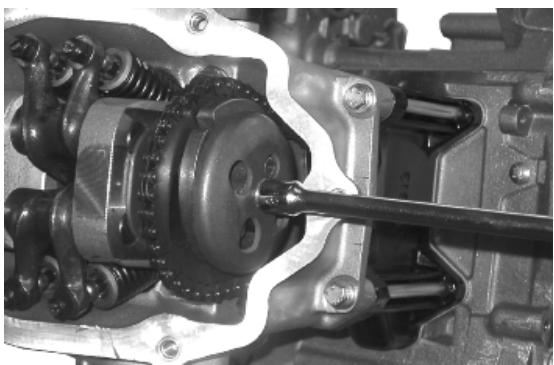
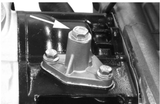
Refitting the rocker-arms cover
- Refit the cylinder head cover, tightening the 5 clamping screws to the prescribed torque.
- Make sure the gasket is positioned properly.
Locking torques (N^*m)
Tappet cover screws 6 - 7 Nm

Refitting the intake manifold
Fit the intake manifold and do up the three screws.
Locking torques (N^*m)
Inlet manifold screws 11 ÷ 13
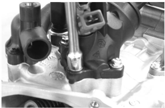
Crankcase - crankshaft
Splitting the crankcase halves
- Before opening the crankcase, it is advisable to check the axial clearance of the crankshaft. To do this, use a plate and a support with appropriate tool dial gauge.
- Upper clearances are an indication of wear on the surfaces of the crankshaft casing support.
- Remove the 10 crankshaft coupling screws.
- Separate the crankcase while keeping the crankshaft in one of the two halves of the crankcase.
- Remove the crankshaft.
- Remove the half crankcase coupling gasket.
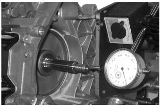
- Remove the two screws and the internal cover shown in the diagram.
- Remove the oil guard on the flywheel side.
- Remove the oil filter fitting shown in the diagram.
- Check the axial clearance on the connecting rod.
-
Check the radial clearance on the connecting rod.
-Check the surfaces that limit the axial free-play are not scored and measure the width of the crankshaft between these surfaces, as shown in the diagram.
-
If the axial clearance between crankshaft and crankcase is exceeding and the crankshaft does not have any defect, the problem must be due to either excessive wear or wrong machining on the crankcase.
- Check the diameters of both the bearings of the crankshaft in accordance with the axes and surfaces shown in the figure. The half-shafts are classified in two categories Cat. 1 and Cat. 2 as shown the chart below.
CAUTION
THE CRANKSHAFT CAN BE REUSED WHEN THE WIDTH IS WITHIN THE STANDARD VALUES AND THE SURFACES SHOW NO SIGNS OF SCORING.
CAUTION
WHILE OPENING THE CRANKCASES AND REMoving THE DRIVING SHAFT, CHECK THAT THE THREADED SHAFT ENDS DO NOT INTERFERE WITH THE MAIN BUSHINGS. FAILURE TO OBSERVE THIS PRECAUTION CAN DAMAGE THE MAIN BUSHINGS.
CAUTION
KEEP THE CRANKSHAFT IN ONE OF THE TWO HALVES OF THE CRANKCASE WHEN SEPARATING IT. IF YOU FAIL TO DO THIS, THE CRANKSHAFT MIGHT ACCIDENTALLY FALL. N.B.
WHEN MEASURING THE WIDTH OF THE CRANKSHAFT, MAKE SURE THAT THE MEASUREMENTS ARE NOT MODIFIED BY THE RADIUSES OF FITTINGS WITH THE CRANKSHAFT BEARINGS.
Specific tooling
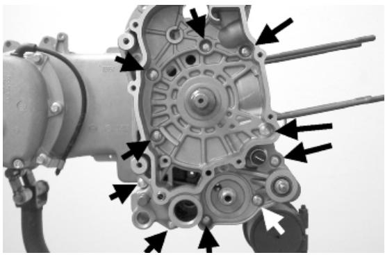
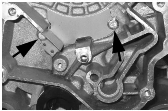
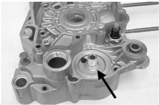
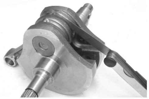
020262Y Crankcase splitting strip
020335Y Magnetic support for dial gauge
Characteristic
Axial crankshaft/crankcase clearance: Standard clearance
0.15 - 0.40 mm (when cold)
Axial connecting rod - crankshaft clearance Standard clearance
0.20 ÷ 0.50 ~mm
Radial connecting rod - crankshaft clearance Standard clearance
0.036 ÷ 0.054 ~mm
Width of crankshaft with integral washers: standard measurements
55.67 ÷ 55.85 ~mm
Crankshaft bearings: Standard diameter: Cat. 1
28.994÷29.000
Crankshaft bearings: Standard diameter: Cat. 2
29.000÷29.006
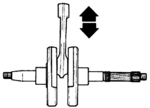
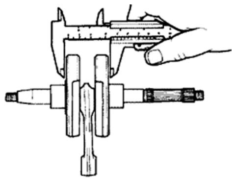
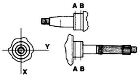
Inspecting the crankshaft alignment
To install the drive shaft on the support and to measure the misalignment in the 4 points indicated in figure.
- Check that the driving shaft cone, the tab seat, the oil seal capacity, the toothed gear and the threaded tangs are in good working order.
- In case of failures, replace the crankshaft.
The connecting rod head bushings cannot be replaced. For the same reason, the connecting rod may not be replaced and, when cleaning the
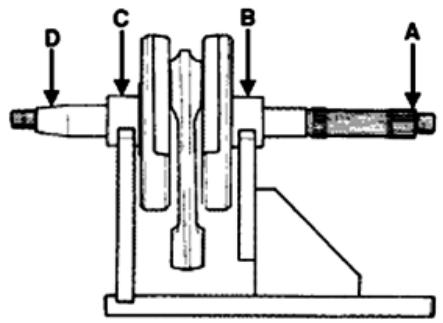
crankshaft, be very careful that no impurities get in through the shaft's lubrication holes.
In order to prevent damaging the connecting rod bushings, do not attempt cleaning the lubrication duct with compressed air.
- Make sure that the 2 caps on the crankpin are properly fitted.
- A wrong installation of a cap can seriously affect the bushing lubrication pressure.
N.B.
THE MAIN BEARINGS ARE NOT GRINDABLE
Specific tooling
020074Y Support base for checking crankshaft alignment
Characteristic
Off-line maximum admitted
A = 0.15 mm
B = 0.01 mm
C = 0.01 ~mm
D=0.10mm
Inspecting the crankcase halves
- Before proceeding to check the crankcase halves, thoroughly clean the all surfaces and oil ducts.
- On the transmission-side crankcase half, take particular care when handling the oil pump compartment and the oil ducts, the by-pass duct, the main bushings and the cooling jet on the transmission side (see diagram).
- Take particular care, also, that there are no signs wear in the oil by-pass valve housing (see Chapter Lubrication), as this could prevent a good seal in the valve, which regulates the oil pressure.
- On the flywheel side crankcase half, take particular care cleaning the oil ducts for the main bushings, the oil duct for the jet that lubricates the cylinder head and the oil drainage duct at the flywheel side oil seal.
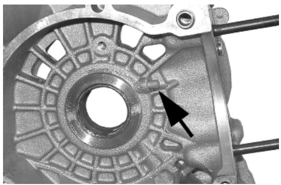
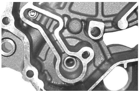
- Inspect the coupling surfaces on the crankcase halves for scratches or deformation, taking particular care with the cylinder/crankcase surfaces and the crankcase halves surfaces.
- Defects in the crankcase coupling gasket between the crankcase halves or the mating surfaces shown in the diagram, could cause a drop in the oil pressure lubricating the main bearings and connection rod.
- Check the main bearing seats that limit axial clearance in the crankshaft show no signs of wear. The dimension between these seats is measured by way of the procedure described previously for measuring the crankshaft axial clearance and dimensions.
N.B.
THE JET IS FED THROUGH THE MAIN BUSHINGS. PROPER OPERATION OF THIS COMPONENT IMPROVES THE PISTON TOP COOLING. CLOGGING HAS EFFECTS THAT ARE DIFFICULT TO DETECT (PISTON TEMPERATURE INCREASE). FAILURE OR LEAK CAN CONSIDERABLY DECREASE THE MAIN BUSHING AND CONNECTING ROD LUBRICATION PRESSURE.
N.B.
THE HEAD LUBRICATION CHANNEL IS PROV- DED WITH A SHUTTER JET; THIS GIVES A "LOW PRESSURE" HEAD LUBRICATION; THIS CHOICE WAS MADE TO REDUCE THE OIL TEMPERATURE IN THE SUMP. THE JET CLOGGING IMPAIRS THE HEAD LUBRICA- TION AND THE TIMING MECHANISMS. A JET FAILURE CAUSES A DECREASE OF THE MAIN BUSHING AND CONNECTING ROD LUBRICA- TION PRESSURE.
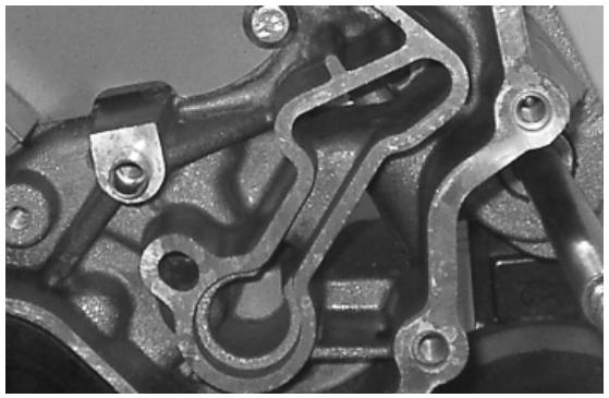
Inspecting the crankshaft plain bearings
-T
o obtain a good bushing lubrication it is necessary to have both an optimal lubricating pressure (3,2 bar) and a good oil flow rate; the bushings must be correctly positioned so as not to obstruct the oil supply channels.
-
The main bushings are comprised of two halfbearings, one with holes and channels for lubrication whereas the other is solid.
-
The solid half-bearing is intended to stand the thrusts caused by combustion, and for this reason it is arranged opposite the cylinder.
-
To prevent obstructions in the oil feeding channels, the matching surface of the two half-bearings must be perfectly perpendicular to the cylinder axis, as shown in the figure.
-
The oil feeding channel section is also affected by the bushings driving depth compared with the crankshaft axial clearance of the limiting surface.
-
Check the inside diameter of the main bushings in the three directions indicated in the diagram.
-
Repeat the measurements for the other bushing half. see diagram.
-
There are three crankcase versions: with RED main bushings, with BLUE main bushings and with YELLOW main bushings.
-
There is only one type of main bushing housing hole in the crankcase
The standard bushing diameter after driving is variable on the basis of a coupling selection.
-
The bushing housings in the crankcase are available in two categories, Cat. 1 and Cat. 2, as are the crankshafts.
-
The main bushings are available in three thickness categories, identified by colour markings, as shown in the table below.
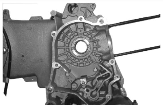
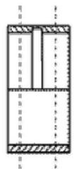
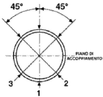
| TYPE | IDENTIFICATION |
| A | RED |
| B | BLUE |
| C | YELLOW |
| Type "A" - RED | Type "B" - BLUE | Type "C" - YEL- LOW |
| Main half- bearing | 1.970 ÷ 1.973 | 1.9703 ÷ 1.976 | 1.976 ÷ 1.979 |
| Bush- ing cat- egy | Crank- case halves category | Internal bush- ing diameter after fitting | Possible fitting |
| A | 1 | 29.025 ÷ 29.040 | Original |
| B | 1 | 29.019 ÷ 29.034 | Original and spare |
| 2 | 29.028 ÷ 29.043 | |
| C | 2 | 29.022 ÷ 29.037 | Original |
Match the shaft with two category 1 crank webs with the category 1 crankcase (or cat. 2 with cat.
2) Furthermore a replacement crankcase cannot be matched with a crankshaft with mixed categories. The replacement crankshaft has half-shafts of the same category.
| Crankcase halves | Engine half-shaft | Bushing |
| Cat. 1 | Cat. 1 | B |
| Cat. 2 | Cat. 2 | B |
| Cat. 1 | Cat. 2 | A |
| Cat. 2 | Cat. 1 | C |
N.B.
TO KEEP THIS POSITION OF THE BUSHINGS ON THE CRANKCASE, FITTING IS FORCED ON STEEL RINGS INSERTED IN THE CASTING OF BOTH CRANKCASE HALVES.
N.B.
DO NOT TAKE THE MEASUREMENT ON THE TWO HALF-SHELL COUPLING SURFACE SINCE THE ENDS ARE RELIEVED TO ALLOW BENDING DURING THE DRIVING OPERATION. N.B.
CRANKCASES FOR REPLACEMENTS ARE SELECTED WITH CRANKCASE HALVES OF THE SAME CATEGORY AND ARE FITTED WITH CATEGORY B BUSHINGS (BLUE)
Characteristic
Standard driving depth
1.35 ÷ 1.6
Diameter of crankcase without bushing
32.953 ÷ 32.963
Refitting the crankcase halves
- Fit the internal bulkhead by locking the two screws to the prescribed torque.
- Fit the oil filter fitting and tighten it to the specified torque.
- Position the oil pre-filter element as shown in the photograph.
- Place a new gasket on one of the crankcase halves, preferably on the transmission side, together with the locating dowels.
- Lubricate the main bushings and insert the crankshaft in the transmission side crankcase half.
- Reassemble the two crankcase halves.
- Fit the 10 screws and tighten them to the prescribed torque.
- Fit a new O-ring on the pre-filter and lubricate it.
- Insert the filter on the engine with the relative cap.
Tighten to the prescribed torque.
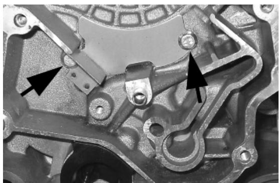
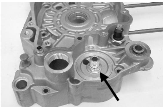
Locking torques (N^*m)
Internal engine crankcase bulkhead (transmission-side half shaft) screws 4 ÷ 6 Engine-crankcase coupling screws 11 ÷ 13 Oil filter on crankcase fitting 27 ÷ 33 Engine oil drainage plug/mesh filter 24 ÷ 30
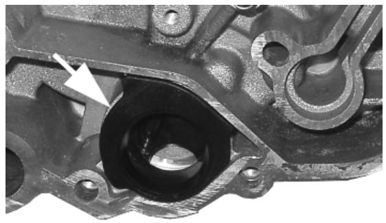
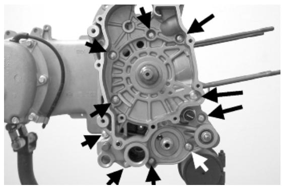
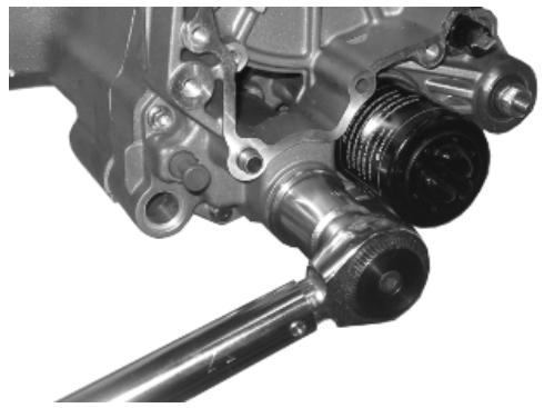
Studs
Check that the stud bolts have not worked loose from their seat in the crankcase.
Check the depth of stud bolt driving with a gauge, as indicated in the photograph. If it varies significantly from the driving depth indicated, it means that the stud bolt has yielded.
In this case, replace it.
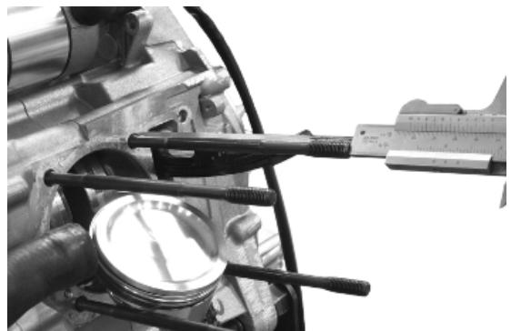
By working on two fitted cylinder head fixing nuts, nut and lock nut, as shown in the photograph, remove the stud bolt from its seat.
Clean the threaded seat on the carter thoroughly. Refit a new stud bolt and apply the special product on the threading crankcase side.
Tighten up to the depth of the driving indicated.
Recommended products
Loctite 'Quick Set' Strong 270 threadlock
Strong 270 threadlock
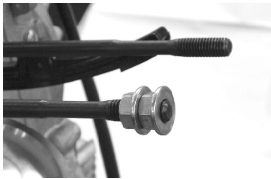
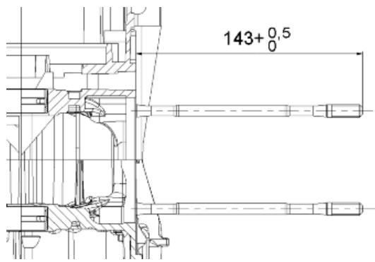
Lubrication
Conceptual diagrams
LUBRICATION CIRCUIT
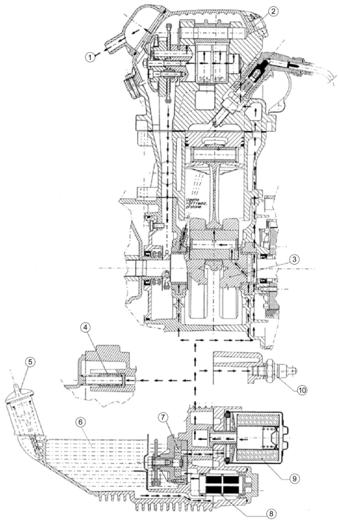
- Engine throttle recovery
- Tappet cover
- Crankshaft
- By-pass valve
- Oil filler
- Oil level in the sump
- Oil pump
- Mesh pre-filter
- Cartridge filter
- Minimum pressure switch
Oil pressure check
- Remove the electrical minimum oil pressure switch connection and remove the switch.
- Connect the coupling and the pressure gauge to check the oil pressure to the hole on the minimum pressure sensor.
- Check the oil pressure reading is between 0.5 and 1.2 atm with the engine idling at 1650 rpm and the oil at the required temperature (wait for at least one electric ventilation).
- Check the oil pressure is between 3.2 and 4.2 atm with the engine running at a speed 6000 rpm and the oil at the required temperature.
- Remove the appropriate tools once the measurement is complete, refit the oil pressure switch and washer, tightening it to the specified torque and fit the fan cover.
- If the oil pressure is not within the specified limits, in the following order, check: the oil filter, the oil by-pass valve, the oil pump and the crankshaft seals.
N.B.
THE CHECK MUST BE CARRIED OUT WITH OIL AT THE CORRECT LEVEL AND WITH AN OIL FILTER IN GOOD CONDITION.
Specific tooling
020193Y Oil pressure gauge
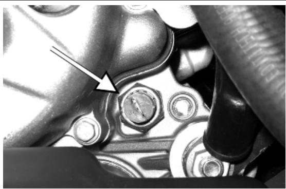
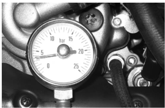
Characteristic
Oil pressure
Minimum pressure admitted at 6000 rpm: 3.2 atm.
Locking torques (N^*m)
Minimum oil pressure sensor 12 ÷ 14
Crankshaft oil seals
Removal
- Remove the transmission cover and the complete driving pulley beforehand
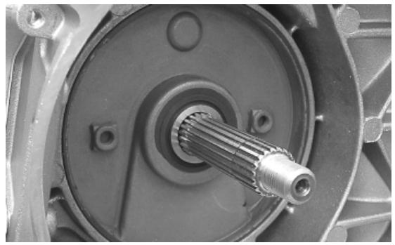
- Install the base of the appropriate tool on the oil guard using the screws provided.
020622Y Transmission-side oil guard punch
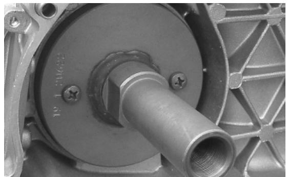
- Screw the threaded bar onto the base of the tool and extract the oil guard.
020622Y Transmission-side oil guard punch
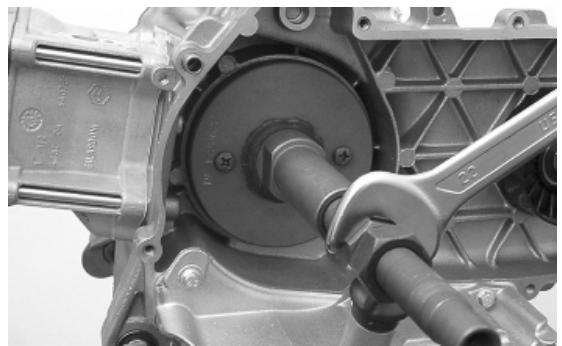
Refitting
- Use a new oil guard for the refitting
- Prepare the new oil guard, lubricating the sealing lip.
- Preassemble the oil seal with the specific tool, positioning the screws.
- Insert the sheath over the crankshaft.
- Insert the tool with the oil seal on the crankshaft until it comes into contact with the crankcase.
- Insert the adaptor bushing of the tool in the hole on the crankcase.
- Orientate the oil guard by inserting the bracket which is part of the appropriate tool
- Tighten the threaded bar onto the crankshaft as far as it will go.
- Use the nut to move the base of the tool until you can see end of the oil guard driving stroke
- Remove all of the tool components following the inverse procedure
CAUTION
DO NOT LUBRICATE THE SURFACE FOR KEYING ONTO THE ENGINE CRANKCASE.
CAUTION
ORIENT THE OIL GUARD BY POSITIONING THE CHAIN HOUSING CHANNEL FACING DOWNWARDS. WHEN THE POSITION IS REACHED, DO NOT RETRACT THE OIL GUARD. FAILURE TO COMPLY WITH THIS RULE CAN CAUSE A WRONG POSITIONING OF THE OIL GUARD SHEATH.
CAUTION
FAILURE TO COMPLY WITH THIS ASSEMBLY PROCEDURE CAN SERIOUSLY DAMAGE THE ENGINE DUE TO THE WRONG TENSIONING OF THE OIL PUMP CONTROL CHAIN.
Specific tooling
020622Y Transmission-side oil guard punch
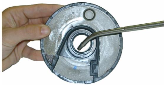
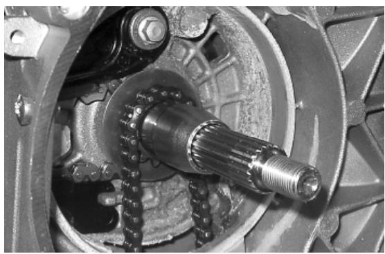
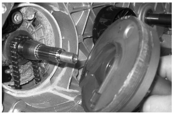
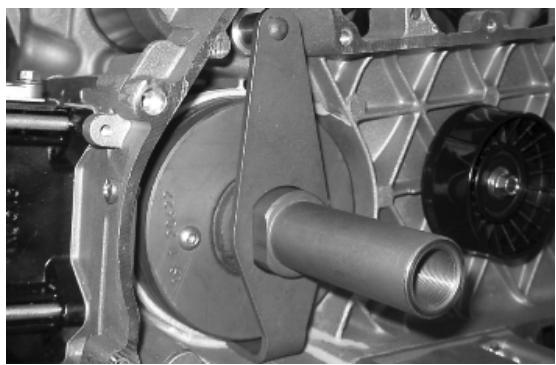
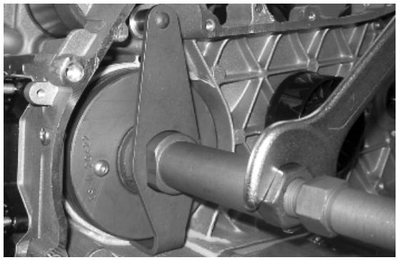
Oil pump
Removal
- Undo the two clamping screws in the figure and remove the cover over the pump control crown.
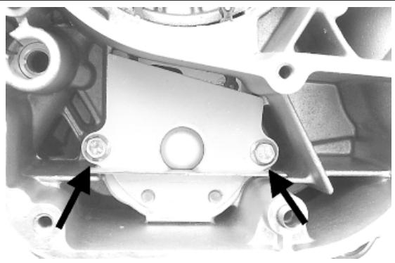
- Block the rotation of the oil pump control pulley with a screwdriver inserted through one of its two holes.
- Remove the central screw with Belleville washer, as shown in the diagram.
- Remove the chain with the crown.
- Remove the control sprocket with relative O-ring.
- Remove the oil pump by unscrewing the two screws in the figure.
- Remove the oil pump seal.
N.B.
IT IS ADVISIBLE TO MARK THE CHAIN IN ORDER TO ENSURE THAT THE INITIAL DIRECTION OF ROTATION IS MAINTAINED.
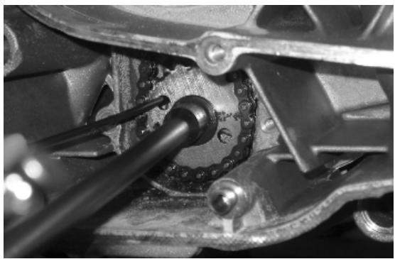
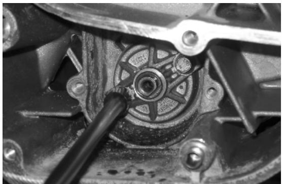
Inspection
- Remove the two screws and the oil pump cover.
- Remove the clip retaining the innermost rotor.
- Remove and wash the rotors thoroughly with petrol and compressed air.
- Reassemble the rotors in the pump body, keeping the two reference marks visible Replace the clip.
- Check the clearance between the rotors in the position shown in the diagram.
Measure the distance between the outer rotor and the pump body (see figure).
- Check the axial clearance of the rotors using a trued bar as shown in the figure.
Characteristic
Axial rotor clearance
Limit values admitted: 0.09mm
Distance between the outer rotor and the pump body
Admissible limit clearance: 0.20mm
Distance between the rotors
Admissible limit clearance: 0.12 mm
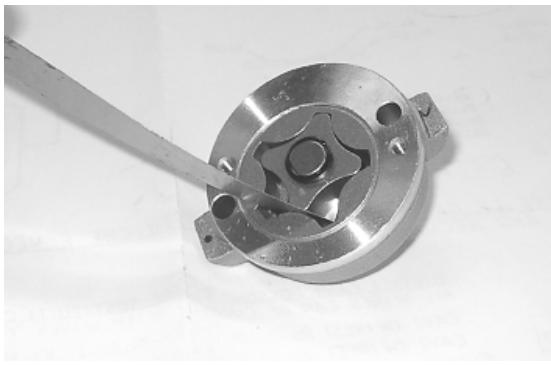
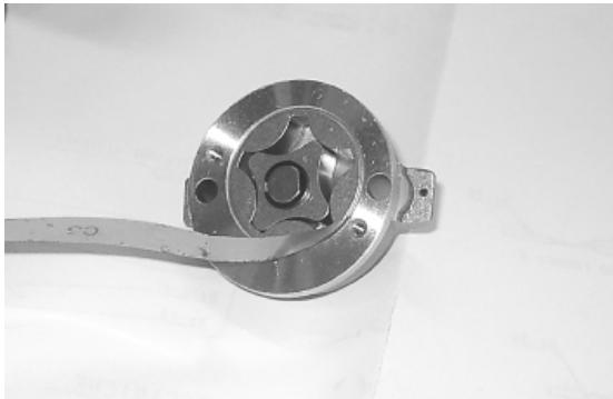
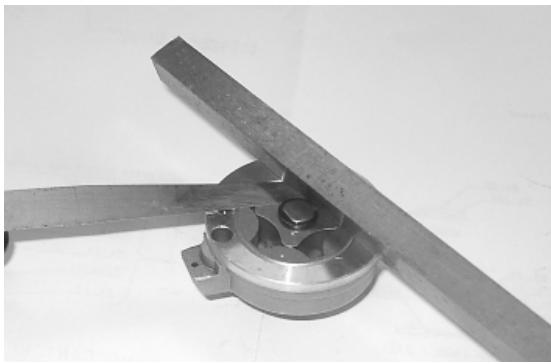
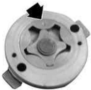
Refitting
- Check there are no signs of wear on the oil pump shaft or body.
- Check there are no signs of scoring or wear on the oil pump cover.
- If you detect non-conforming measurements or scoring, replace the faulty parts or the unit.
- Fit the pump cover in the position that permits the crankcase fixing screws to be aligned.
- Make sure the gasket is positioned properly and refit the pump on the engine crankcase. The pump can only be fitted in one position. - Tighten the screws to the prescribed torque.
- Fit the sprocket wheel with a new O-ring.
- Fit the chain.
- Fit the central screw and the belleville washer.
Tighten to the prescribed torque.
- Fit the oil pump cover by tightening the two screws to the prescribed torque.
N.B.
FIT THE BELLEVILLE WASHER SO THAT ITS OUTER RIM TOUCHES THE PULLEY. MAKE SURE THAT THE PUMP TURNS FREELY.
Locking torques (N^*m)
Screws fixing oil pump to the crankcase 5 - 6 Oil pump control crown screw 10 ÷ 14 Oil pump cover screws 0.7 ÷ 0.9
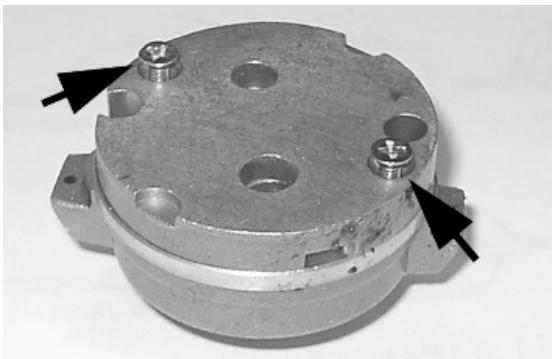
Removing the oil sump
- Remove the oil filler plug, the transmission cover, the complete driving pulley assembly with belt and the sprocket wheel, as described in the "Transmission" chapter.
- Drain the oil as described previously.
- Remove the seven screws, shown in the diagram, and the two rear brake fluid pipe fixing brackets.
- Remove the screw, the by-pass piston, the gasket and centring dowels shown in the figure.
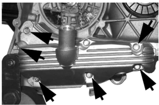
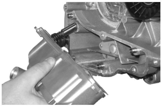
Inspecting the by-pass valve
- Check the unloaded spring length.
- Check that the small piston is not scored.
- Ensure that it slides freely on the crankcase and that it guarantees a good seal.
- If not, eliminate any impurities or replace defective parts.
Characteristic
By-pass check up: Standard length
54.2 mm

Refitting the oil sump
- Refit the by-pass valve plunger in its housing.
- Insert the pressure-regulating spring.
- Fit a new sump seal.
- Refit the two centring dowels.
- Refit the sump, taking care to locate the spring in the appropriate recess machined into the inside of the sump.
- Refit the rear brake cable brackets and the screws in the reverse order from which they were removed.
- Tighten the screws to the prescribed torque.
- Refit the drive pulley assembly, the drive belt, the sprocket wheel and the transmission cover, as described in the "Transmissions" chapter.
N.B.
WHEN CHECKING THE LUBRICATION SYSTEM, REFER TO THE «CRANKCASE AND
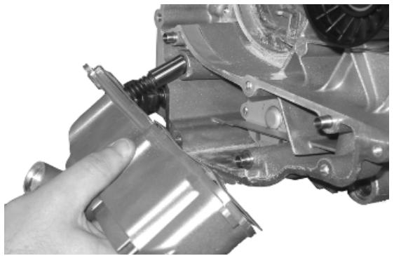
CRANKSHAFT》 CHAPTER ON LUBRICATING THE CRANKSHAFT AND CONNECTING ROD.
Locking torques (N^*m)
Oil sump screws 10 ÷ 14
INDEX OF TOPICS
INJECTION
INJEC

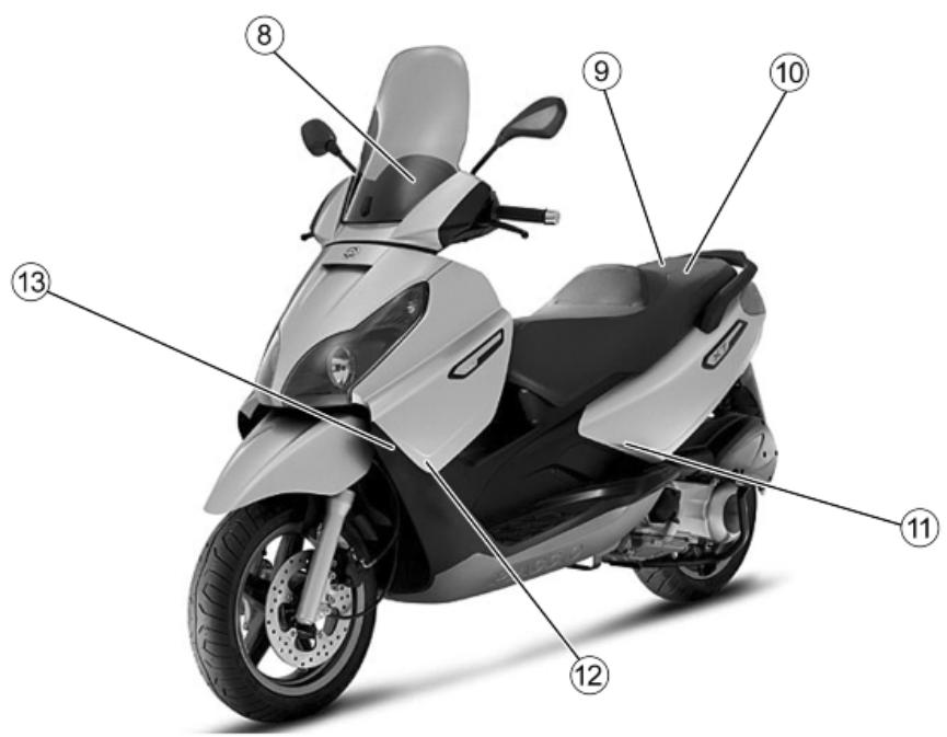
INJECTION COMPONENTS
| Specification | Desc./Quantity |
| 1 | Throttle body and electronic injection control unit (MIU) | |
| 2 | Fuel injector | |
| 3 | Injection load remote control | |
| 4 | Electric fan starter | |
| 5 | HV coil | |
| 6 | Lambda sensor | |
| 7 | Water temperature sensor | |
| 8 | Instrument panel | |
| 9 | Battery | 12V - 12 Ah |
| 10 | Diagnostics socket connector | |
| 11 | Engine rpm sensor | |
| 12 | Fuel pump | |
| 13 | Electric fan | |
MIU injection system
This vehicle is fitted with an integrated injection and ignition system.
Injection is indirect in the manifold through an electro-injector.
The injection and ignition are timed on the four-stroke cycle by means of a tone wheel keyed on to the crankshaft (24-2 teeth) and pick-up sensor.
Combustion and ignition are managed on the basis of engine revs and throttle valve opening. Further corrections are made according to the following parameters:
- Coolant temperature.
- Intake air temperature
- Lambda probe strength
The system implements an idle feeding correction with cold engine through a Stepper motor on a bypass circuit of the throttle valve. The control unit manages the Stepper motor and the injector opening time, thereby ensuring the idle steadiness and the proper combustion.
In all conditions of use, mixture preparation is managed by modifying the injector opening time.
The fuel supply circuit consists of:
-Fuel pump
-Fuel filter
-Injector
- Pressure regulator
The pump, the filter and the regulator are placed inside the fuel tank on a single support.
The injector is connected by a delivery pipe.
The fuel pump is controlled by the MIU control unit ; this ensures the scooter safety
The ignition circuit consists of:
-HV coil
- HV cable
- Shielded cap
- MIU control unit
- Spark plug
The MIU control unit manages ignition with the best advance ensuring four-stroke timing (ignition only in the compression phase) at the same time.
The MIU injection-ignition system controls engine functions by means of a pre-set program.
Should any input signals fail, an acceptable working order of the engine is ensured to allow the user to reach a service station.
Of course, this cannot happen when the rev counter signal is missing, or when the failure involves the control circuits:
-Fuel pump
- HV coil
-Injector
The control unit is provided with a self-diagnosis system connected to an indicator light in the instrument panel.
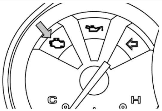
Failures are detected and restored by the diagnostic tester.
In any case, when the fault is no longer present, the data storage is automatically cleared after 16 cycles of use (cold start, running at regular engine temperature, stop).
The diagnostic tester is also required to adjust the idle mixture.

020460Y Scooter diagnosis and tester
The MIU injection-ignition system carries out checks on the rpm counter and the electric fan for radiator cooling.
The MIU control unit power supply is furthermore controlled by the emergency switch; that is to provide further safety for the scooter.
Precautions
Troubleshooting hints
1 - A failure of the EMS system is more likely to be due to the connections than to the components.
Before troubleshooting the MIU system, carry out the following checks:
A: Electrical power supply
a. Battery voltage
b. Blown fuse
c. Remote controls
d. Connectors
B: Chassis earthing
C. Fuel supply
a. Broken fuel pump
b. Dirty fuel filter
D: Ignition system
a. Faulty spark plug
b. Broken coil
c. Broken shielded cap
E: Intake circuit
a. Dirty air filter
b. Dirty by-pass circuit
c. Faulty Stepper motor
F: Other
a. Incorrect distribution timing
b. Wrong idle mixture
c.Incorrect reset of the throttle valve position sensor
2 - MIU system faults may be caused by loose connectors. Make sure that all connections are properly implemented.
Check the connectors being careful of the following:
-
check that the terminals are not bent.
-
check that the connectors have been connected up properly.
-
check whether the failure changes making the connector vibrate slightly.
3 - check the entire system thoroughly before replacing the MIU control unit. If the fault is fixed by replacing the MIU control unit, install the original control unit again and check if the fault occurs again.
4 - Use a multimeter with an internal resistance of more than 10K Ohm/V when troubleshooting. Instruments that are not suitable might damage the MIU central control unit. Use instruments with definitions over 0.1V and 0.5W, the precision must be greater than 2% .
- Before fixing any part of the injection system, check to see if there are any registered faults. Do not disconnect the battery before checking for faults.
-
The fuel feed system is pressurised at 250kPa (2.5 BAR). Before disconnecting the quick coupler of a pipe in the fuel supply system, check that there are no naked flames, and do not smoke. Act with caution to prevent spraying in the eyes.
-
When fixing electric components, operate with battery connected only when actually required.
- When functional checks are performed, check that the battery voltage is more than 12V.
- Before trying to start up, check to make sure there is at least two litres of fuel in the tank. Failure to respect this norm will damage the fuel pump.
- If the scooter is expected to remain unused for a long time, refill the tank up to a little over half the level. This will ensure the pump will be covered by fuel.
- When washing the vehicle, be careful with the electric components and wiring.
- When an ignition fault is detected, start the checks from the battery and the injection system connections.
-
Before disconnecting the MIU control unit connector, perform the following steps in the order shown:
-
Set the switch to «OFF»
-
Disconnect the battery
Failure to respect this norm may damage the control unit.
- Do not invert the polarity when fitting the battery.
- To avoid damage, only disconnect and reconnect the MIU system connectors if required. Before reconnecting, check that the connectors are dry.
- When carrying out electric inspections, do not force the tester probes into the connectors. Do not take measurements not specifically foreseen by the manual.
- At the end of every check performed with the diagnostic tester, protect the system connector with its cap. Failure to do this may damage the MIU control unit.
- Before reconnecting the quick couplers of the power supply system, check that the terminals are perfectly clean.
Terminals setup
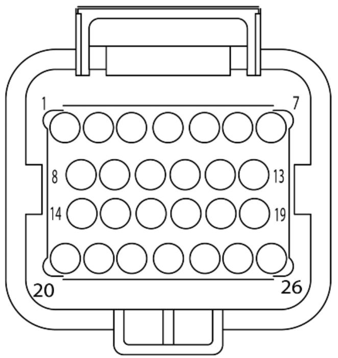
TERMINAL LAYOUT
| Specification | Desc./Quantity |
| 1 | Injection warning light | |
| 2 | - | |
| 3 | - | |
| 4 | Lambda probe negative | |
| 5 | Live supply | |
| 6 | Battery-powered | |
| 7 | - | |
| 8 | Electric fan starter | |
| 9 | Water temperature sensor | |
| 10 | - | |
| 11 | Lambda probe positive | |
| 12 | Engine stop switch | |
| 13 | R.P.M. sensor (+) | |
| 14 | Fuel injector | |
| 15 | R.P.M. sensor (-) | |
| 16 | Diagnostics socket output | |
| 17 | - | |
| 18 | Ground lead | Connected with: water temperature sensor, engine stop switch. |
| 19 | Headlight remote control | |
| 20 | Injection load remote control | |
| 21 | Lambda probe heater | |
| 22 | HV coil | |
| 23 | - | |
| 24 | Start up enabling | |
| 25 | - | |
| 26 | Ground lead | Connected with: water temperature sensor, engine stop switch. |
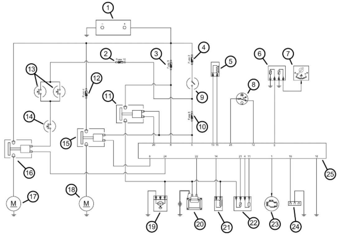
EMS circuit diagram
SYSTEM SCHEMATIC
| Specification | Desc./Quantity |
| 1 | Battery | 12V - 12 Ah |
| 2 | Fuse | 7.5 A |
| 3 | Fuse | 15A |
| 4 | Fuse | 15A |
| 5 | Engine rpm sensor | |
| 6 | Water temperature sensor | |
| 7 | Water temperature gauge | |
| 8 | Engine stop switch | |
| 9 | Key switch contacts | |
| 10 | Fuse | 7.5 A |
| 11 | Injection load remote control | |
| 12 | Fuse | 15A |
| 13 | Stop button | |
| 14 | Starter button | |
| 15 | Electric fan starter | |
| 16 | Starter remote control | |
| 17 | Starter motor | |
| 18 | Electric fan | |
| 19 | Fuel pump | |
| 20 | HV coil | |
| 21 | Fuel injector | |
| 22 | Lambda sensor | |
INJEC-8
| Specification | Desc./Quantity |
| 23 | "WARNING" light | |
| 24 | Diagnostics socket connector | |
| 25 | Injection ECU | |
Troubleshooting procedure
Engine does not start
ENGINE DOES NOT START IF ONLY PULLED
| Possible Cause | Operation |
| Presence of faults detected by the self diagnosis | Pump relay
HV coil
Injector
revolution timing sensor |
| Fuel supply | Fuel in the tank
Fuel pump activation
Fuel pressure (low)
Injector capacity (low) |
| Power to the spark plug | Shielded spark-plug cap HV coil (secondary insulation) |
| Parameter reliability | Coolant temperature
Distribution timing - injection ignition
Intake air temperature |
| End of compression pressure | End of compression pressure |
Starting difficulties
ENGINE START-UP PROBLEMS
| Possible Cause | Operation |
| Presence of faults detected by the self diagnosis | Pump relay
HV coil
Injector
revolution timing sensor
Air temperature
Coolant temperature |
| Start up engine speed | Starter motor and remote control
Battery
Ground connections
Stepper |
| End of compression pressure | End of compression pressure |
| Power to the spark plug | Spark plug
Shielded cap
HV coil
Revolution timing sensor
Ignition advance |
| Fuel supply | Fuel in the tank
Fuel pressure (low)
Injector capacity (low)
Injector seal (poor) |
| Correctness of the parameters | Coolant temperature |
| Stepper throttle valve position intake air temperature (steps and actual opening) |
| Cleaning of the auxiliary air pipe and throttle valve; air filter efficiency |
Engine stops at idle
ENGINE DOES NOT HOLD IDLING/ IDLING IS UNSTABLE/ IDLING TOO LOW
| Possible Cause | Operation |
| Presence of faults detected by the self diagnosis | Pump relay
HV coil
Injector
revolution timing sensor
Air temperature
Coolant temperature |
| Ignition efficiency | Spark plug
Ignition timing |
| Correctness of the parameters | Throttle valve position sensor
Stepper
Coolant temperature sensor
Intake air temperature sensor |
| Intake system cleaning | Air filter
Diffuser and throttle valve
Additional air pipe and Stepper |
| Intake system sealing (infiltrations) | Intake manifold - head
Throttle body - manifold
Intake sleeve
Filter box |
| Fuel feed (low pressure) | Fuel pump
Pressure regulator
Fuel filter
Injector capacity |
Engine does not rev down
ENGINE DOES NOT RETURN TO THE IDLING SPEED/IDLING SPEED TOO HIGH
| Possible Cause | Operation |
| Presence of faults detected by the self diagnosis | Pump relay
HV coil
Injector
revolution timing sensor
Air temperature
Coolant temperature |
| Ignition efficiency | Ignition timing |
| Correctness of the parameters | Throttle valve position sensor
Stepper
Coolant temperature sensor
Intake air temperature sensor |
| Intake system sealing (infiltrations) | Intake manifold - head
Throttle body - manifold
Intake sleeve
Filter box |
| Fuel feed (low pressure) | Fuel pump
Pressure regulator
Fuel filter
Injector capacity |
Exhaust backfires in deceleration
EXHAUST BACKFIRESH WHEN DECELERATING
| Possible Cause | Operation |
| Presence of faults detected by the self diagnosis | Pump relay
HV coil
Injector
revolution timing sensor
Air temperature
Coolant temperature
Lambda sensor |
| Correctness of the parameters | Throttle valve position sensor
Stepper
Coolant temperature sensor
Intake air temperature sensor |
| Intake system sealing (infiltrations) | Intake manifold - head
Throttle body - manifold
Intake sleeve
Filter box |
| Fuel feed (low pressure) | Fuel pump
Pressure regulator
Fuel filter
Injector capacity |
| Exhaust system sealing (infiltrations) | Manifold - head
Manifold - muffler
Muffler welding |
Engine revs irregularly
ENGINE IRREGULAR PROGRESS WITH VALVE SLIGHTLY OPEN
| Possible Cause | Operation |
| Intake system cleaning | Air filter
Diffuser and throttle valve
Additional air pipe and Stepper |
| Intake system seal | Intake sleeve
Filter box |
| Ignition system | Spark plug wear check |
| Parameter reliability | Throttle valve position signal
Coolant temperature indicator
Intake air temperature indicator
Ignition advance |
| TPS reset successful | TPS reset successful |
| Presence of faults detected by the self diagnosis | Pump relay
HV coil
Injector
revolution timing sensor
Air temperature |
| Coolant temperature
Lambda sensor |
POOR ENGINE PERFORMANCE AT FULL POWER/ ENGINE IRREGULAR PROGRESS ON PICKUP
| Possible Cause | Operation |
| Presence of faults detected by the self diagnosis | Pump relay
HV coil
Injector
revolution timing sensor
Air temperature
Coolant temperature
Lambda sensor |
| Spark plug power supply | Spark plug
Shielded cap
HV cable
HV coil |
| Intake system | Air filter
Filter box (sealing)
Intake sleeve (sealing) |
| Parameter reliability | Throttle valve position signal
Coolant temperature indicator
Intake air temperature indicator
Ignition advance |
| Fuel supply | Fuel level in the tank
Fuel pressure
Fuel filter
Injector capacity |
Engine knocking
PRESENCE OF KNOCKING (HEAD KNOCKING)
| Possible Cause | Operation |
| Presence of faults detected by the self diagnosis | Pump relay |
| HV coil |
| Injector |
| revolution timing sensor |
| Air temperature |
| Coolant temperature |
| Lambda sensor |
| Ignition efficiency | Spark plug |
| Parameter reliability | Throttle valve position signal |
| Coolant temperature indicator |
| Intake air temperature indicator |
| Ignition advance |
| Intake system seal | Intake sleeve |
| Filter box |
| TPS reset successful | TPS reset successful |
| Fuel supply | Fuel pressure |
| Fuel filter |
| Injector capacity |
| Fuel quality |
| Selection of the cylinder base gasket thickness | Selection of the cylinder base gasket thickness |
Fuel supply system
The fuel supply circuit includes the electric pump, the filter, the pressure regulator, the electro-injector and the fuel delivery pipes.
The electrical pump is located in the tank from which the fuel is pumped and sent to the injector through the filter.
The pressure is controlled by the pressure regulator situated in the pump assembly in the tank.
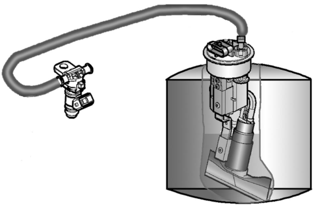
Removing the butterfly valve
Remove the fuel piping clamping screw indicated in the figure.
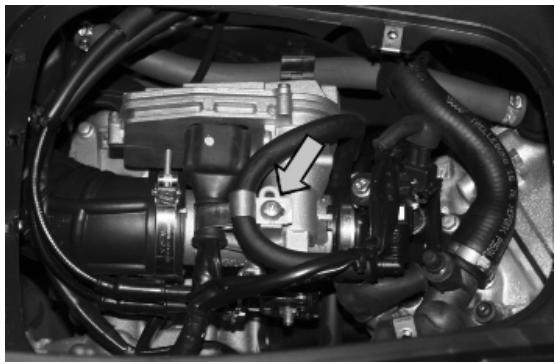
Remove the fast-release fitting from the injector support
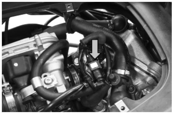
Remove the injector connector
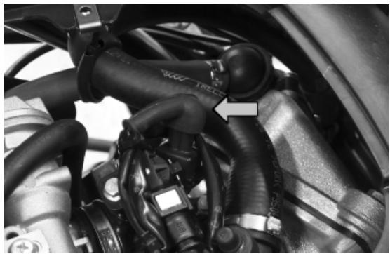
Remove the three screws fixing the manifold to the cylinder head and the clip fixing the throttle body to the manifold.
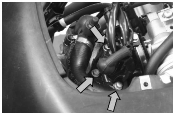
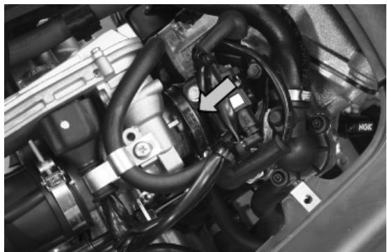
Remove the MIU connector
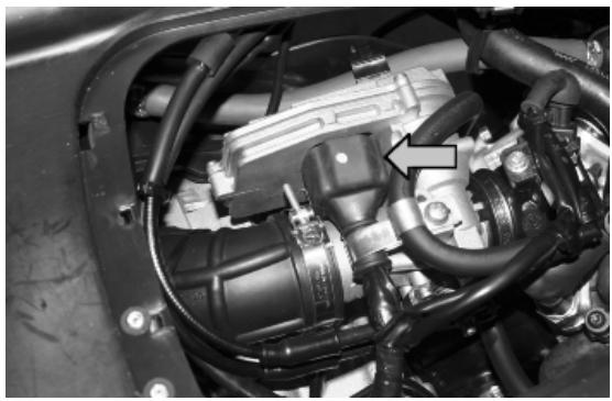
Remove the clip fixing the throttle body to the purifier bellows
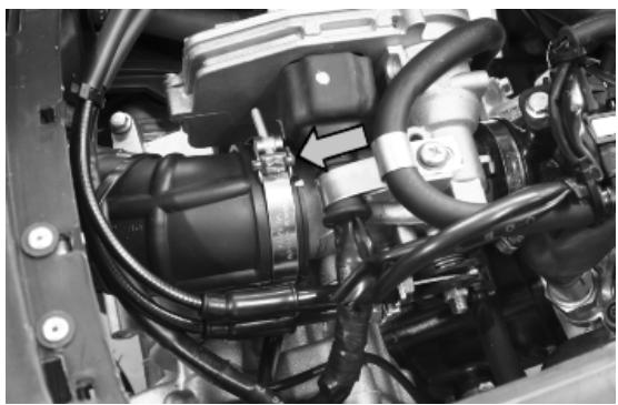
Remove the gas control retainers as indicated in the photograph
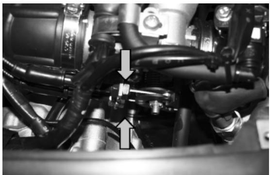
Refitting the butterfly valve
To refit, perform the operations in the reverse order from the removal operations being careful to position the clip fixing the throttle body to the air filter bellows at 45^ as shown in the photograph.

Pump supply circuit
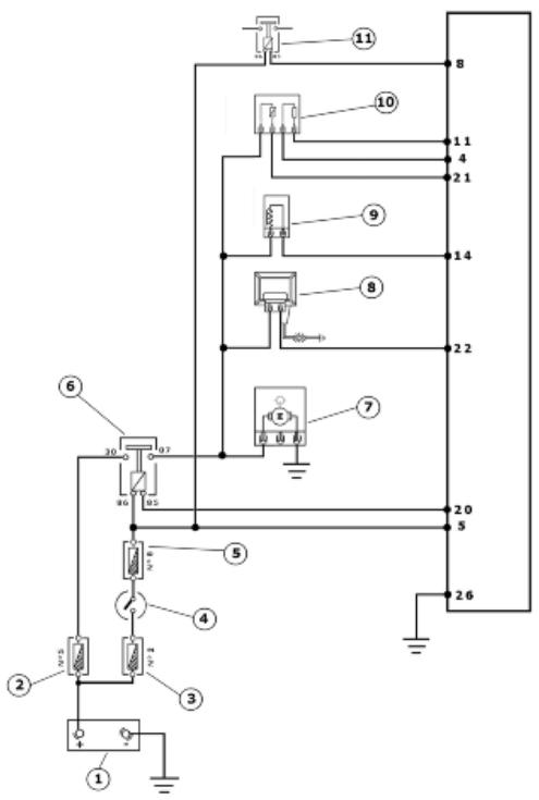
INJECTION LOADS
| Specification | Desc./Quantity |
| 1 | Battery | 12V - 12 Ah |
| 2 | Fuse | 15A |
| 3 | Fuse | 15A |
| 4 | Key switch contacts | |
| 5 | Fuse | 7.5 A |
| 6 | Injection load remote control | |
| 7 | Fuel pump | |
| 8 | HV coil | |
| 9 | Fuel injector | |
| 10 | Lambda sensor | |
| 11 | Electric fan starter | |
When switched to "ON", the fuel pump starts to rotate for two seconds and then stops. When the engine starts up, in the presence of rpm timing signal the pump is continuously supplied.
ELECTRICAL DATA
- Pump winding resistance ~ 1.5 Ohm
- Input current during normal functioning 1.4 ÷ 1.8 A
- Input current to the closed hydraulic circuit 2 A (to be checked with specific tool for fuel pressure control, choking the circuit on the return pipe)
Check the efficiency of 15A fuse No. 5 (injection load).
Check the efficiency of 7.5A fuse No. 8 (live ECU power).
Check the efficiency of the injection load remote control: measure the resistance of the drive coil between pins 86 and 85.
Characteristic
Drive coil resistance
40÷ 80
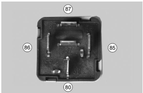
Apply a voltage of 12V to pins 86 and 85; make sure that there is continuity between pins 30 and 87 of the remote control.
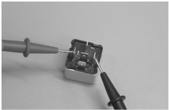

Check the power supply line of the injection load remote control energising coil: after switching to «ON», make sure there is battery voltage, for 2 seconds, between the Red-Green cable and the Black-Purple cable of the remote control base. If there is not, check the continuity of the Red-Green cable between the fuse box (fuse No. 8) and the remote control base and of the Black-Purple cable between pin 20 of the ECU and the remote control base.
N.B.
CONTINUITY TESTS MUST BE CARRIED OUT WITH THE COMPONENTS DISCONNECTED. (REMOTE CONTROLS, CONTROL UNIT, FUSES ETC.).


Check if there is steady voltage between the Orange-Blue cable of the remote control base and the ground lead. If there is not, check the continuity of the Orange-Blue cable between the fuse box (15A fuse No. 5) and the remote control base.
N.B.
CONTINUITY TESTS MUST BE CARRIED OUT WITH THE COMPONENTS DISCONNECTED. (REMOTE CONTROLS, CONTROL UNIT, FUSES ETC.).
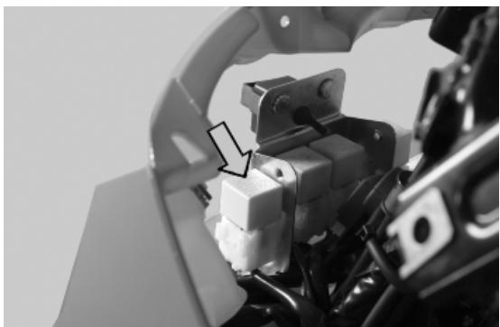
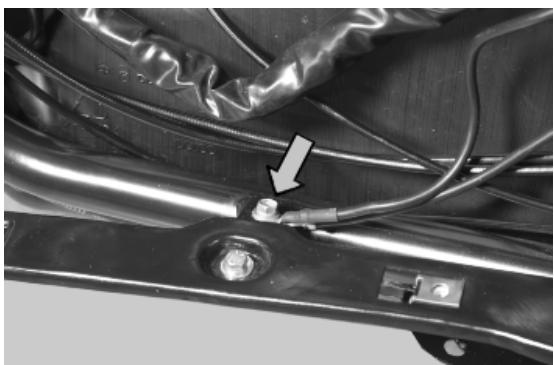
After switching to «ON», check that there is battery voltage, for about 2 seconds, between the Black-Green cable of the pump connector and the ground lead with the pump connector disconnect- ted. Otherwise, check the continuity of the Black- Green cable between the pump connector and the remote control base.
Check the efficiency of the earth line of the fuel pump by measuring the continuity between the pump connector black cable, system side, and the ground lead.
If, when switching to «ON», the pump continues to turn after 2 seconds of activation, check, with the
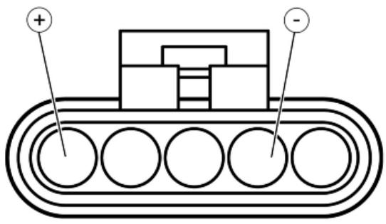
control unit disconnected and the injection load remote control disconnected, that the Black-Purple cable (pin 20 on the interface wiring) is insulated from the ground.
020331Y Digital multimeter
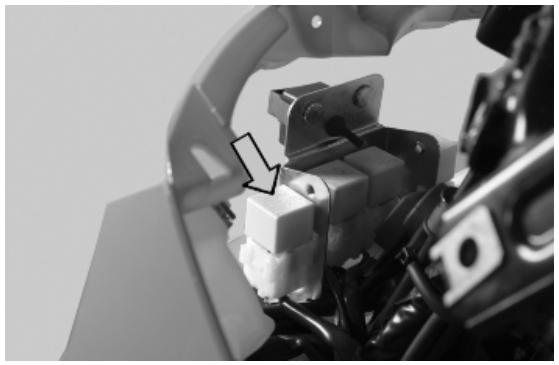
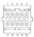
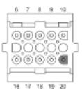
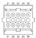
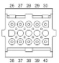
Circuit leak test
Install the appropriate tool for fuel pressure control with the pipe fitted with the pressure gauge on the delivery pipe..

Check during regular operation by placing the appropriate tool between the pump and the injector. With the battery voltage >12~V check that the fuel pressure is 2.5 BAR and that the input current is 1.4 to 1.8 A

With the battery voltage >12~V , check the pump flow rate by disconnecting from the injector the pipe equipped with the pressure gauge of the appropriate tool. Make a graded burette available with a flow rate of approximately 1 L. Rotate the pump using the active diagnosis of the palm top computer. Using
a pair of long flat needle-nose pliers, choke the fuel pipe making the pressure stabilise at approx. 2.5 BAR. Check that, in fifteen seconds, the pump has a flow rate of around 110~cm^3
020480Y Petrol pressure check set
Fuel filter check
Disconnect the terminals from the electric pump
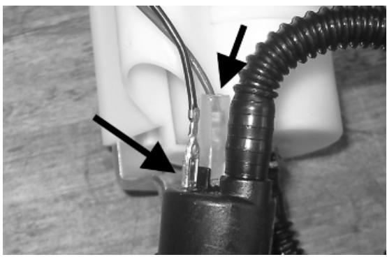
Remove the screw shown in the photograph
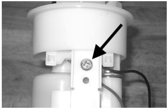
Remove the clip fixing the piping to the filter shown in the photograph
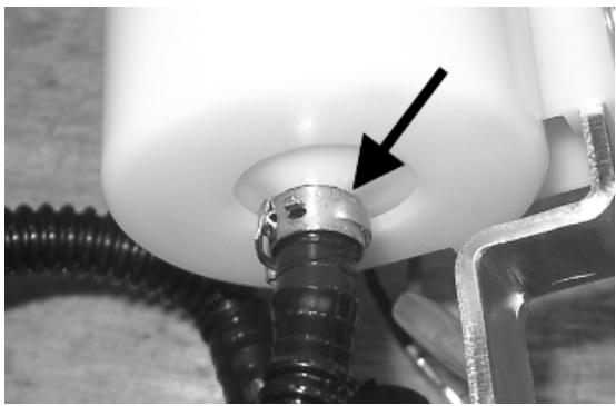
Separate the lower part of the pump support as shown in the photograph.
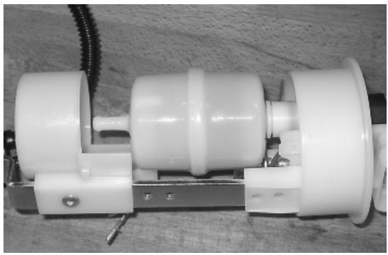
Remove the filter from the pump support
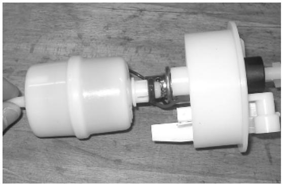
Inspecting the injector circuit

INJECTION LOADS
| Specification | Desc./Quantity |
| 1 Battery | 12V - 12 Ah |
| Specification | Desc./Quantity |
| 2 | Fuse | 15A |
| 3 | Fuse | 15A |
| 4 | Key switch contacts | |
| 5 | Fuse | 7.5 A |
| 6 | Injection load remote control | |
| 7 | Fuel pump | |
| 8 | HV coil | |
| 9 | Fuel injector | |
| 10 | Lambda sensor | |
| 11 | Electric fan starter | |
Check the resistance at the injector ends: 14.5 ± 5% Ohm
Check the efficiency of 15A fuse No. 5 (injection load).
Check the efficiency of 7.5A fuse No. 8 (live ECU power).
Check the efficiency of the injection load remote control: measure the resistance of the drive coil between pins 86 and 85.
Characteristic
Drive coil resistance
$$
4 0 \div 8 0 \Omega
$$
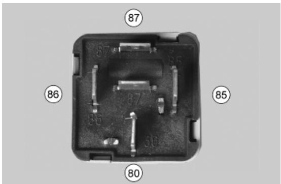
Apply a voltage of 12V to pins 86 and 85; make sure that there is continuity between pins 30 and 87 of the remote control.

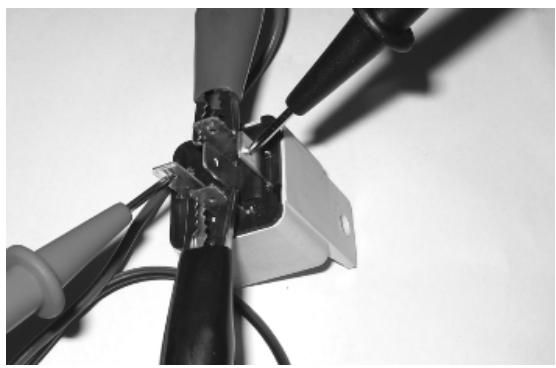
Check the power supply line of the injection load remote control energising coil: after switching to «ON», make sure there is battery voltage, for 2 seconds, between the Red-Green cable and the Black-Purple cable of the remote control base. If there is not, check the continuity of the Red-Green cable between the fuse box (fuse No. 8) and the remote control base and of the Black-Purple cable between pin 20 of the ECU and the remote control base.
N.B.
CONTINUITY TESTS MUST BE CARRIED OUT WITH THE COMPONENTS DISCONNECTED. (REMOTE CONTROLS, CONTROL UNIT, FUSES ETC.).

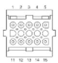
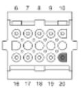
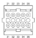
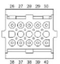
Check if there is steady voltage between the Orange-Blue cable of the remote control base and the ground lead. If there is not, check the continuity of the Orange-Blue cable between the fuse box (15A fuse No. 5) and the remote control base.
N.B.
CONTINUITY TESTS MUST BE CARRIED OUT WITH THE COMPONENTS DISCONNECTED. (REMOTE CONTROLS, CONTROL UNIT, FUSES ETC.).
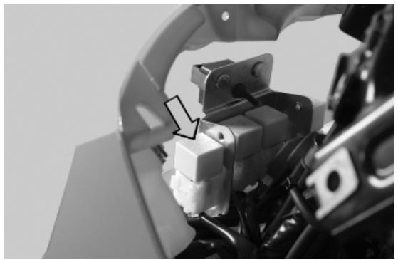
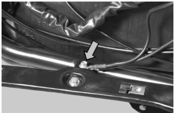
With the control unit and the injector disconnected, check the continuity of the Red-Yellow cable between pin 14 of the interface wiring and the injector connector
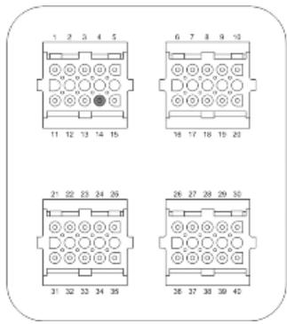
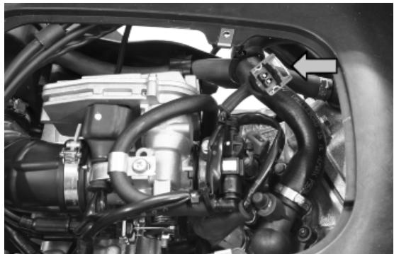
Switch to "ON" and check if there is voltage, with injector disconnected and control unit connected, between the Black-Green cable of the injector connector and the ground lead

With injector disconnected and the injector load remote control disconnected, check the continuity of the Black-Green cable between the injector connector and remote control base.

Inspecting the injector hydraulics
To carry out the injector check, remove the intake manifold by removing the three clamping screws at the head and the clip connecting the control unit to the manifold.
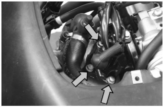
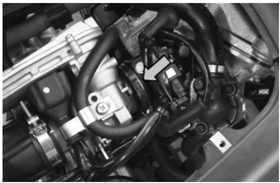
Install the appropriate tool for checking fuel pressure and position the manifold over a container graduated by at least 100~cm^3 . Connect the injector with the cable making up part of the supply for the injection tester. Connect the clamps of the cable to an auxiliary battery. Activate the fuel pump with the active diagnosis. Check that, in fifteen seconds, approximately 40 cc of fuel is dispensed with a regulation pressure of approximately 2.5 BAR.
Specific tooling
020480Y Petrol pressure check set
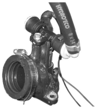
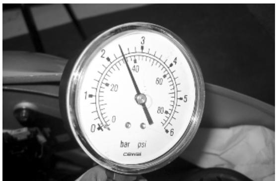
Proceed with the injector seal test.
Dry the injector outlet with a blast of compressed air. Activate the fuel pump. Wait for one minute, making sure there are no leaks coming from the injector. Slight oozing is normal.
Value limit = 1 drop per minute
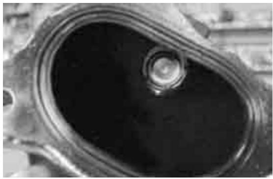
Components location
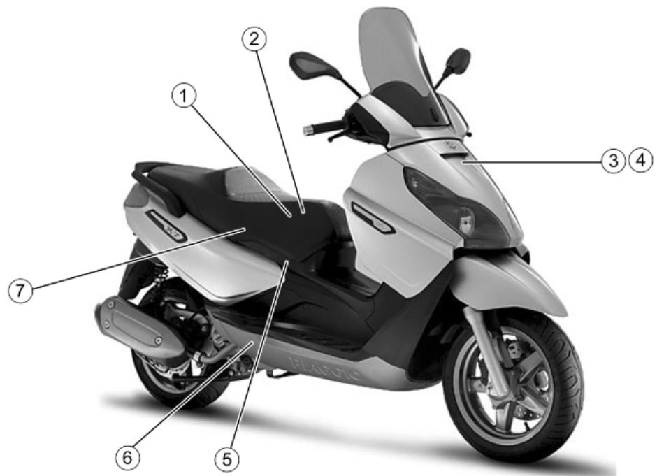
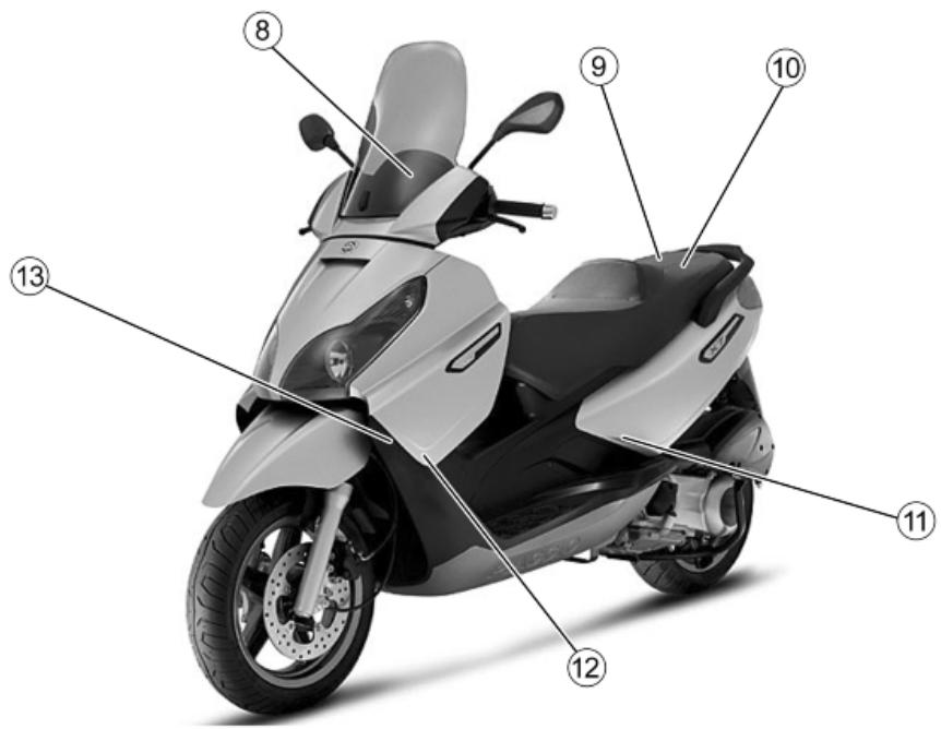
INJECTION COMPONENTS
| Specification | Desc./Quantity |
| 1 | Throttle body and electronic injection control unit (MIU) | |
| 2 | Fuel injector | |
| 3 | Injection load remote control | |
| 4 | Electric fan starter | |
| 5 | HV coil | |
| 6 | Lambda sensor | |
| 7 | Water temperature sensor | |
| 8 | Instrument panel | |
| 9 | Battery | 12V - 12 Ah |
| 10 | Diagnostics socket connector | |
| 11 | Engine rpm sensor | |
| 12 | Fuel pump | |
| 13 | Electric fan | |
Tachometer
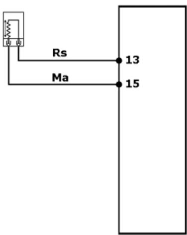
With wiring disconnected from the control unit and connected to the system, check that the sensor resistance between pins 13 - 15 is between 100 and 150 Ohm at an engine temperature of approximately 20^
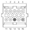

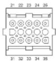
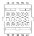
Disconnect the fuel pipe connector. Start up the engine and wait for it to stop. With the wiring connected to the control unit and system try to start up the engine and check that the voltage between pins 13 and 15 is around 2.8V
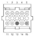

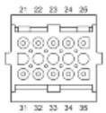
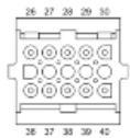
With the interface cable harness disconnected from the control unit, check continuity between pin 13 and the red cable of the rpm sensor connector and between pin 15 and the brown cable of the rpm sensor connector
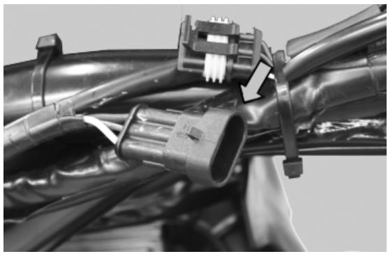
With the interface wiring disconnected from the control unit and rpm sensor connector, check that the red and brown cables (pin 13 - 15) are isolated from each other and insulated from the earth.
Specific tooling
020481Y Control unit interface wiring
020331Y Digital multimeter
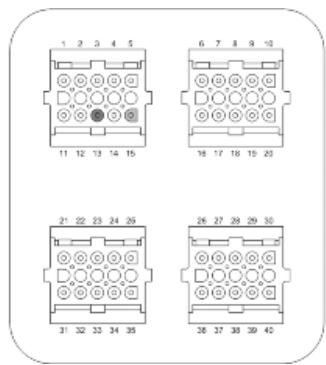
HT coil
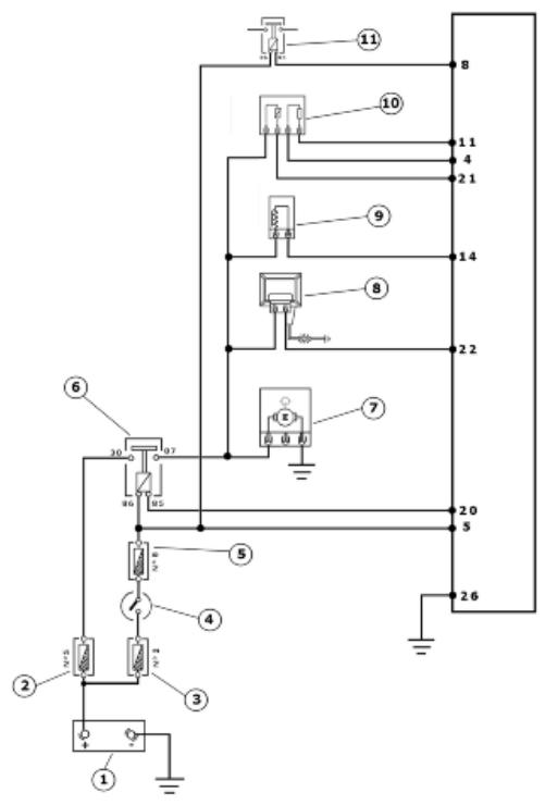
INJECTION LOADS
| Specification | Desc./Quantity |
| 1 Battery | 12V - 12 Ah |
| Specification | Desc./Quantity |
| 2 | Fuse | 15A |
| 3 | Fuse | 15A |
| 4 | Key switch contacts | |
| 5 | Fuse | 7.5 A |
| 6 | Injection load remote control | |
| 7 | Fuel pump | |
| 8 | HV coil | |
| 9 | Fuel injector | |
| 10 | Lambda sensor | |
| 11 | Electric fan starter | |
The ignition system is integrated with the injection and is of the inductive high efficiency type.
The control unit manages two important parameters:
This is optimised according to the engine rpm, to the engine load, temperature and ambient pressure. With idle engine, it is optimised to obtain the stabilisation of the speed at 1450 ± 50 R / 1' .
The coil magnetisation time is controlled by the control unit. The ignition power is increased during the engine start-up.
The injection system recognises the 4-stroke cycle and therefore, ignition is only controlled during compression.
020331Y Digital multimeter
Check the efficiency of 15A fuse No. 5 (injection load).
Check the efficiency of 7.5A fuse No. 8 (live ECU power).
Check there is voltage between pins 22 and 26 of the interface wiring for around two seconds when switching to «ON».
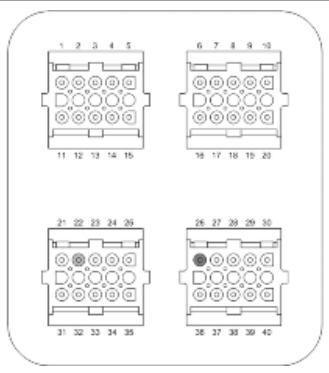
Check the resistance of the primary coil between pin 22 of the interface wiring and the Black-Green cable of the injection load remote control base, with the control unit disconnected and the remote control disconnected.
Characteristic
HV coil resistance primary value:
0.9
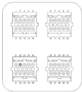
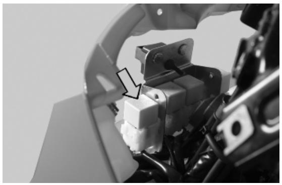
Check the efficiency of the injection load remote control: measure the resistance of the drive coil between pins 86 and 85.
Characteristic
Drive coil resistance
40÷ 80

Apply a voltage of 12V to pins 86 and 85; make sure that there is continuity between pins 30 and 87 of the remote control.


Check the power supply line of the injection load remote control energising coil: after switching to «ON», make sure there is battery voltage, for 2 seconds, between the Red-Green cable and the Black-Purple cable of the remote control base. If there is not, check the continuity of the Red-Green cable between the fuse box (fuse No. 8) and the remote control base and of the Black-Purple cable between pin 20 of the ECU and the remote control base.
N.B.
CONTINUITY TESTS MUST BE CARRIED OUT WITH THE COMPONENTS DISCONNECTED. (REMOTE CONTROLS, CONTROL UNIT, FUSES ETC.).
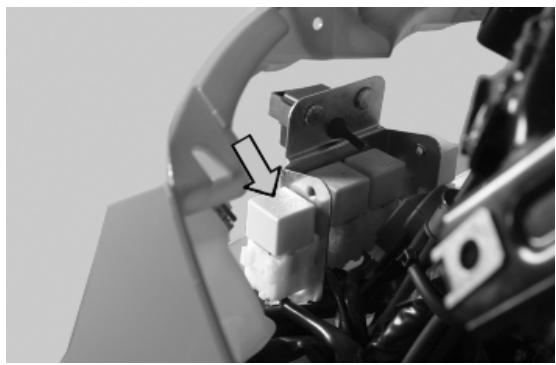
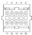
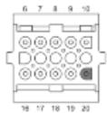
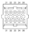
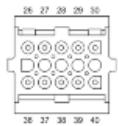
Check if there is steady voltage between the Orange-Blue cable of the remote control base and the ground lead. If there is not, check the continuity of the Orange-Blue cable between the fuse box (15A fuse No. 5) and the remote control base.
N.B.
CONTINUITY TESTS MUST BE CARRIED OUT WITH THE COMPONENTS DISCONNECTED. (REMOTE CONTROLS, CONTROL UNIT, FUSES ETC.).
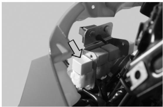
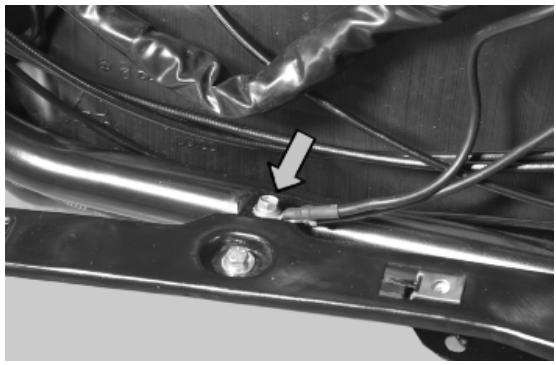
Coolant temperature sensor
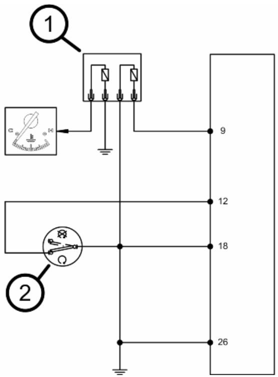
TEMPERATURE SENSOR 1
| Specification | Desc./Quantity |
| 1 | Water temperature sensor | |
| 2 | Engine stop switch | |
With the connector on the control unit side disconnected and the coolant temperature sensor connector connected, check that the resistance values between pins 9 and 18 correspond to the engine temperature.
$$
2 0 ^ {\circ} = 2 5 0 0 \pm 1 0 0 \Omega
$$
$$
8 0 ^ {\circ} = 3 0 8 \pm 6 \Omega
$$
With the connector on the control unit side disconnected and the coolant temperature sensor connector disconnected, check the insulation between the two Grey-Green and Yellow-Pink cables.
With the connector on the control unit side disconnected and the coolant temperature sensor connector disconnected, check the continuity between pin 9 of the interface wiring and the Yellow-Pink cable of the connector, and between pin 18 of the interface wiring and the Grey-Green cable of the connector.
020481Y Control unit interface wiring 020331Y Digital multimeter
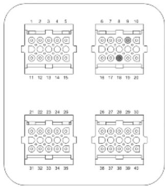
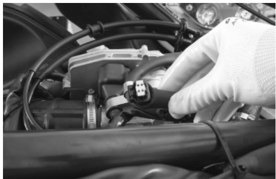
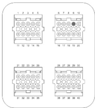
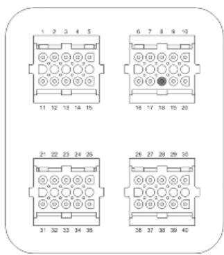
Zeroing the throttle
Resetting the throttle valve position signal (TPS reset)
The MIU control unit is supplied with a throttle valve position sensor that is pre-calibrated.
Pre-calibration entails regulating the minimum opening of the throttle valve to obtain a certain flow of air under pre-set reference conditions.
Pre-calibration ensures optimal air flow to control idling.
This regulation must not be tampered with in any way whatsoever.
The injection system will complete the management of the idling through the Stepper motor and the variation of the ignition advance.
The throttle body after the pre-calibration has an opened valve with an angle that can vary depending on the tolerances of the machining of the pipe and the valve itself.
The valve position sensor can also assume various fitting positions. For these reasons the mV of the sensor with the valve at idle can vary from one throttle body to another.
To obtain the optimum fuel mixture, especially at small openings of the throttle valve, it is essential to match the throttle body with the control unit following the procedure known as TPS resetting.
With this operation we inform the control unit, as the starting point, of the mV value corresponding to the pre-calibrated position.
To reset, proceed as follows.
Connect the diagnostic tester.
Switch to «ON».
Select the functions of the diagnostic tester on «TPS RESET».
020460Y Scooter diagnosis and tester

Make sure that the throttle valve with the control is supporting the stop screw.
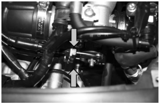
Guaranteeing that this position will be kept, send a confirmation for the TPS reset procedure.
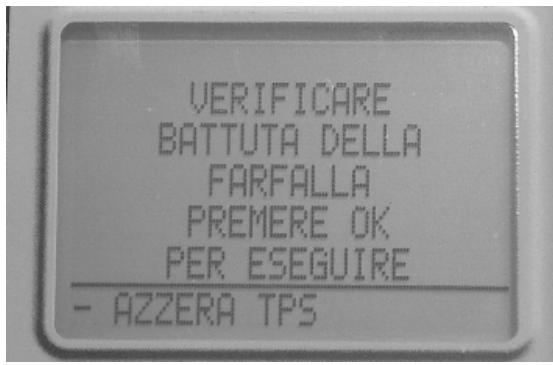


Reset should be performed in the following cases:
-on first fitting.
- if the injection control unit is replaced.
N.B.
THE TPS RESETTING PROCEDURE MUST NOT BE CARRIED OUT WITH A USED THROTTLE BODY BECAUSE POSSIBLE VALVE WEAR AND STOP WEAR FOR THE MINIMUM OPENING MAKE THE AIR FLOW DIFFERENTLY FROM THAT OF PRE-CALIBRATION.
Given that the TPS resetting is also done when the control unit is replaced, place the control unit - filter box bellows at 45^ during the refitting operation as shown in the photograph.
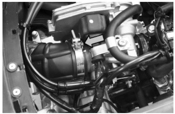
Lambda probe

INJECTION LOADS
| Specification | Desc./Quantity |
| 1 | Battery | 12V - 12 Ah |
| 2 | Fuse | 15A |
| 3 | Fuse | 15A |
| 4 | Key switch contacts | |
| 5 | Fuse | 7.5 A |
| 6 | Injection load remote control | |
| 7 | Fuel pump | |
| 8 | HV coil | |
| 9 | Fuel injector | |
| 10 | Lambda sensor | |
| 11 | Electric fan starter | |
| The Lambda sensor or oxygen sensor is a sensor which provides indications concerning the oxygen content in the exhaust gas. The signal generated is not of the proportional type but of the ON/OFF type, |
i.e. there is oxygen or there is not. The sensor is positioned on the exhaust manifold before the catalytic converter in an area where the gas temperature is always high. The temperature at which the sensor works is at least 350^ at 600^ and it has a reaction time of just 50 milliseconds. The signal generated passes from a high value to a low value with a mixture with lambda =1 . Since the sensor only works at high temperatures, it has an electric preheating element inside it, controlled by the control unit, to take it quickly to the functioning state.
020481Y Control unit interface wiring
020331Y Digital multimeter
Check the efficiency of 15A fuse No. 5 (injection load).
Check the efficiency of 7.5A fuse No. 8 (live ECU power).
Check there is voltage between pins 21 and 26 of the interface wiring, for around two seconds, when switching to «ON».
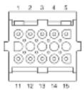
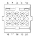
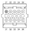
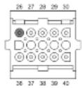
With the engine cold, check the resistance of the Lambda sensor heater between pin 21 of the interface wiring and the black green cable of the injection load remote control base, with the control unit disconnected and the remote control disconnected.
Resistance of the heater at approximately 20^ = 9 Ohm ± 20%
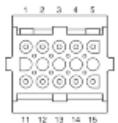
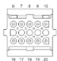
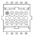
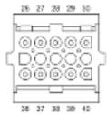

Check the efficiency of the injection load remote control: measure the resistance of the drive coil between pins 86 and 85.
Characteristic
Drive coil resistance
40÷ 80

Apply a voltage of 12V to pins 86 and 85; make sure that there is continuity between pins 30 and 87 of the remote control.
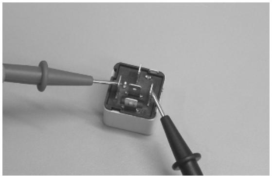
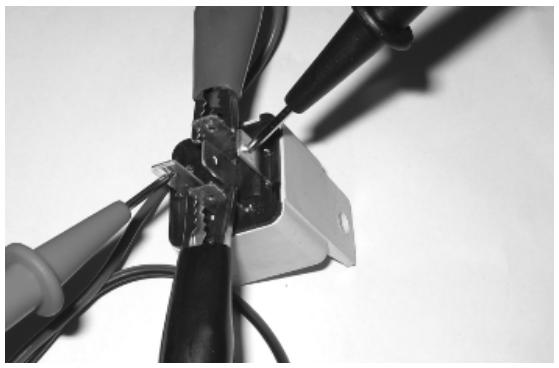
Check the power supply line of the injection load remote control energising coil: after switching to «ON», make sure there is battery voltage, for 2 seconds, between the Red-Green cable and the Black-Purple cable of the remote control base. If there is not, check the continuity of the Red-Green cable between the fuse box (fuse No. 8) and the remote control base and of the Black-Purple cable between pin 20 of the ECU and the remote control base.
N.B.
CONTINUITY TESTS MUST BE CARRIED OUT WITH THE COMPONENTS DISCONNECTED. (REMOTE CONTROLS, CONTROL UNIT, FUSES ETC.).

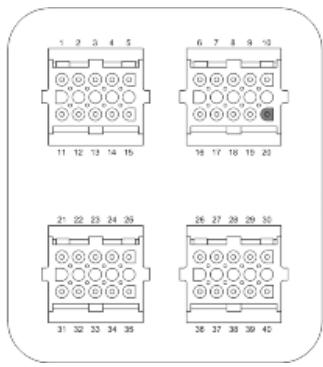
Check if there is steady voltage between the Orange-Blue cable of the remote control base and the ground lead. If there is not, check the continuity of the Orange-Blue cable between the fuse box (15A fuse No. 5) and the remote control base.
N.B.
CONTINUITY TESTS MUST BE CARRIED OUT WITH THE COMPONENTS DISCONNECTED. (REMOTE CONTROLS, CONTROL UNIT, FUSES ETC.).


SIGNAL CONTROL
Install the electronic control unit interface wiring.
Start the engine and warm up until the electric fan switches on.
Use an analogue multimeter with a direct voltage scale measuring down to 2V .
Place the tips of the multimeter between pins 4 (-) and 11 (+)
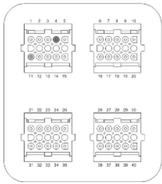
With the engine running at idle speed, check that the voltage oscillates between 0V and 1V
With the throttle valve completely open, the voltage is approx. 1V
During the closing phase, the voltage is approx. 0V.
If the voltage remains constant, the sensor may be damaged. Remove the sensor and check that there are no oil or carbon deposits inside it..
INDEX OF TOPICS
SUSPENSIONS
SUSP
This section is devoted to operations that can be carried out on the suspension.
Front
Removing the front wheel
- Remove the fixing nut from the wheel axle on the left side of the vehicle.
- Loosen the two screws fixing the wheel axle clamp and remove the clamp.
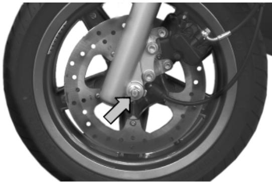
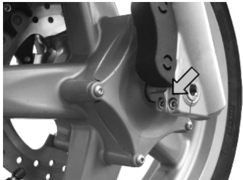
Front wheel hub overhaul
Check that the wheel bearings do not show signs of wear.
If you have to replace the wheel bearings, proceed as follows:
- Remove the two bearings on the brake disc side using pliers 14 and the special bell 9.
- Remove the internal spacer.
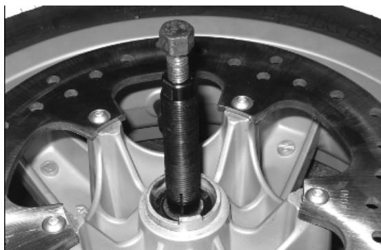
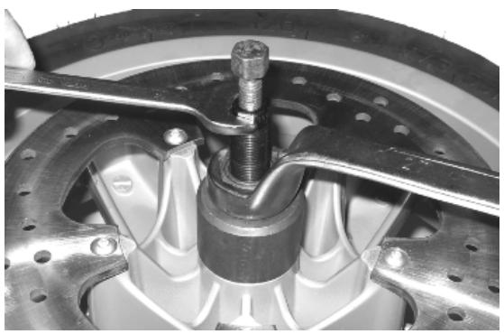
- Support the front wheel with two wooden shims that make it possible to avoid scratching in the case of contact with the rim.
- Insert the punch (consisting of adaptor handle, 24mm adaptor and 15mm guide) from the brake disc side to permit the removal of the opposite side bearing and the spacer bushing.
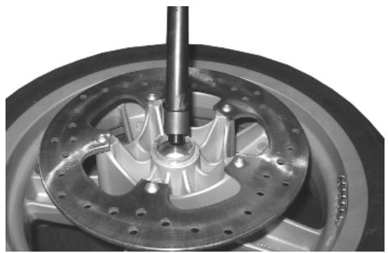
020376Y Adaptor handle
020456Y 0 24 mm adaptor
020412Y 15 mm guide
- Heat the bearing seat on the side opposite the brake disc with the heat gun.
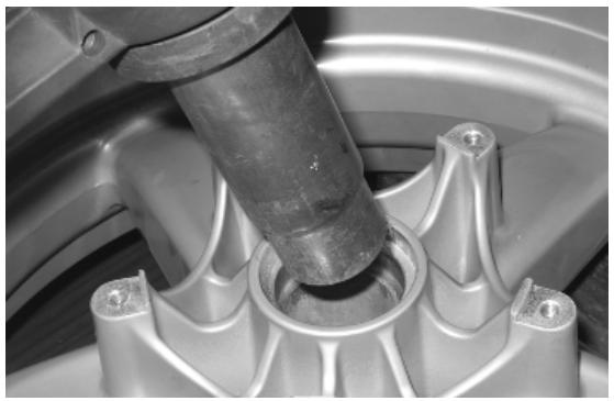
- Insert the bearing using the punch consisting of adaptor handle, 40 × 37 ~mm adaptor and 15 ~mm guide, and take it to the stop.
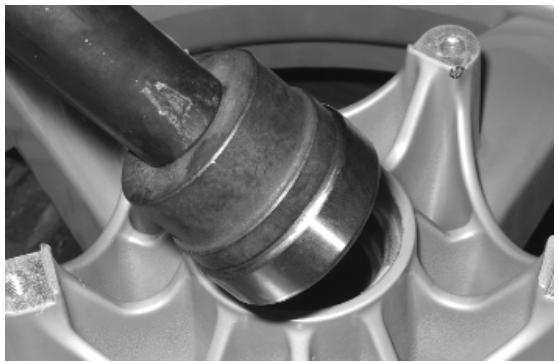
- Reinsert the spacer bushing on the brake disc side using the appropriate tool and take it to the stop.
020376Y Adaptor handle
020359Y 42x47-mm adaptor
020412Y 15 mm guide
020201Y Spacer bushing driving tube
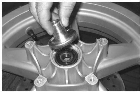
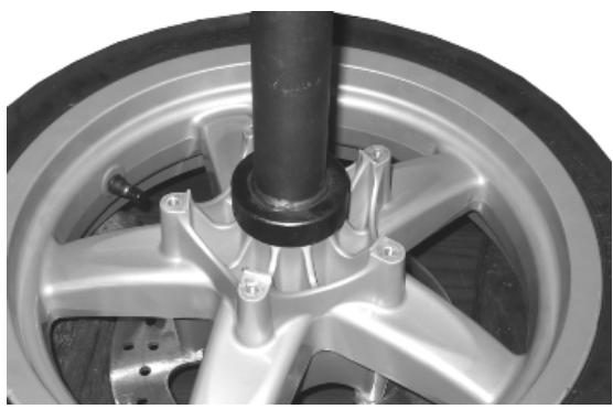
- Refit the cap and tighten the five fixing screws.
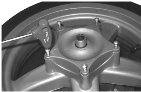
- Turn over the wheel and insert the internal spacer with the part fitted with the seeger ring facing the bearing on the brake disc side.
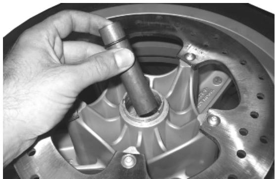
- Heat the bearing seat on the side the brake disc with the heat gun.
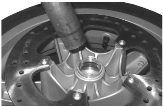
2 - Insert the two bearings one at a time using the punch consisting of adaptor handle, 32x35 mm adaptor and 15 mm guide, and take it to the stop.
020376Y Adaptor handle
020357Y 32 x 35 mm adaptor
020412Y 15 mm guide
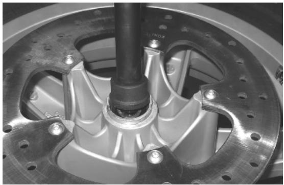
Refitting the front wheel
- Carry out the operations described in the «removal» section but in reverse order.
Locking torques (N^*m)
Wheel axle nut 45 ÷ 50 Wheel axle clamp screws 6 - 7 Nm
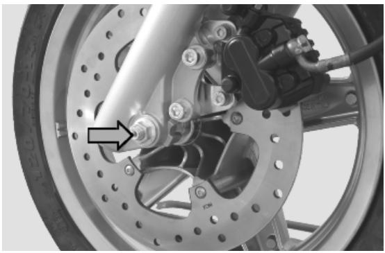
Handlebar
Removal
- Remove the handlebar covers as explained in the «Bodywork» Chapter.
- Remove the handlebar wiring retaining straps and disconnect the electric connectors from the brake levers.
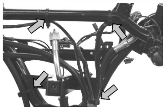
- Unscrew the clamps of the U-bolts and release the brake pumps.
- Remove the flexible transmission of the throttle grip and remove the throttle control.
- Loosen the clamp fixing the handlebar to the steering tube and remove the handlebar by pulling it upwards.
N.B.
IF THE HANDLEBAR IS BEING REMOVED TO REMOVE THE STEERING, IT IS ONLY NECESSARY TO TILT THE HANDLEBAR FORWARD ONTO THE FRONT PART OF THE VEHICLE WITHOUT REMOVING THE PARTS FITTED SO AS TO AVOID DAMAGING THE SHAFTS.
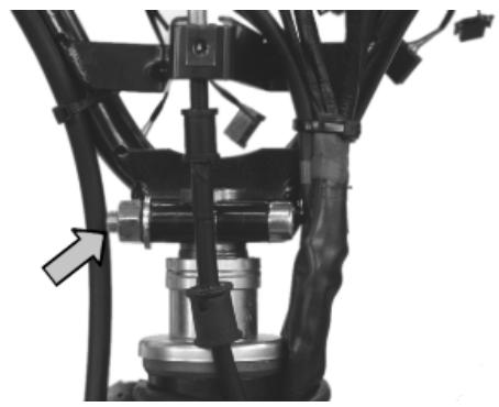
Refitting
Carry out the above operations by following the removal steps but in reverse order, respecting the handlebar-steering tube alignment as shown in the figure.
Locking torques (N^*m)
Handlebar fixing screw (^*) 43÷47
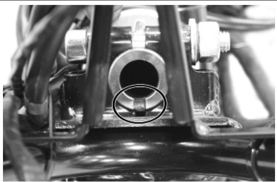
Front fork
Removal
See also
SUSP-6
Removal
Overhaul
- Support the fork in a vice.
- Loosen the two tightening screws of the stem supporting clamp.
- Unscrew the stem closing cap and slide off the complete fork leg from the corresponding support.
CAUTION
THE STEM CLOSING CAP KEeps THE MAIN SPRING PRELOADED. KEEP THE CAP PROPERLY FITTED DURING THE REMOVAL FINAL STAGE TO AVOID ACCIDENTS.
- Support the fork leg properly, remove the main spring and drain off the fork leg oil.
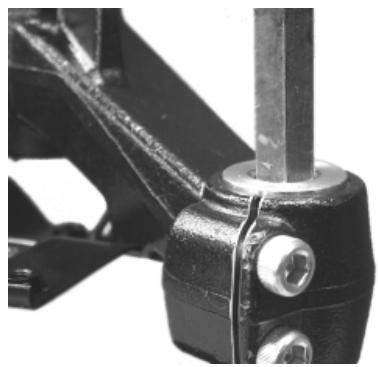
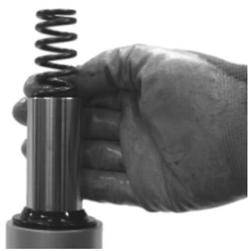
- Remove the hydraulic rod fixing screw with the corresponding sealing gasket:
- With a 19-mm hexagonal spanner, lock hydraulic rod rotation.
- Undo the fixing screw and collect the copper washer.
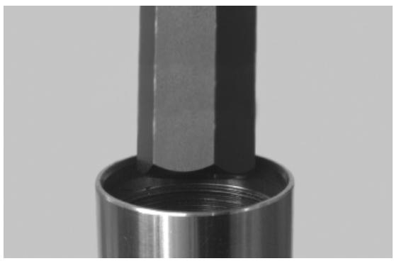
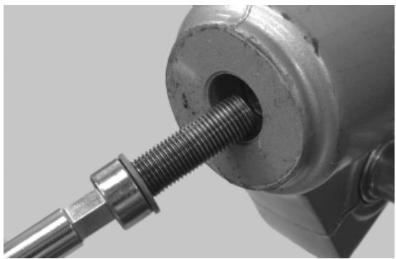
- Remove the stem dust guard with a screwdriver.
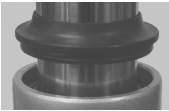
- Remove the circlip retaining the oil seal.
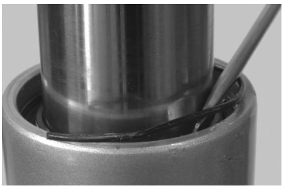

- Check there are no signs of wear or seizing between the stem and the fork leg. Otherwise, replace the damaged parts.
Characteristic
Maximum leg diameter
35.10 mm
Minimum stem diameter
34.90 mm
- Take out the oil seal using the appropriate tools.
- Fit the tie rod into the oil seal.
- Insert in sequence the two half-rings per 0 mm stems.
020487Y Fork oil seal extractor
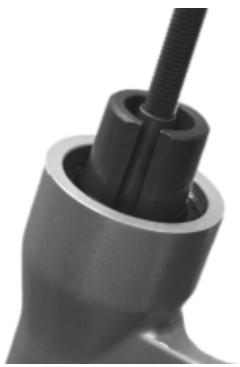
020487Y Fork oil seal extractor
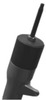
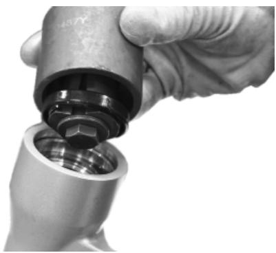
- Remove the hydraulic rod with the corresponding sealing gasket, the spring and the stop bushing.
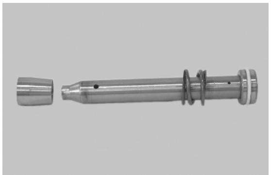
COMPONENT CHECK
CAUTION
CLEAN ALL THE COMPONENTS THOROUGHLY.
- Check that the fork leg is not cracked or broken in the attachments.
- Check that the stem is not scored, dented or distorted.
- Check that the stop bushing for the hydraulic rod is correctly fixed through caulking.
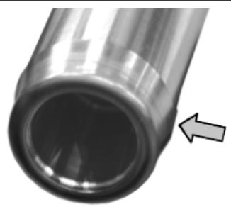
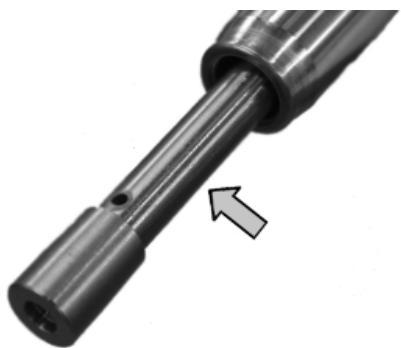
- Check that hydraulic rod caulkings, the contrast spring to the unloaded the end of stroke and the hydraulic rod sealing ring are in good conditions.
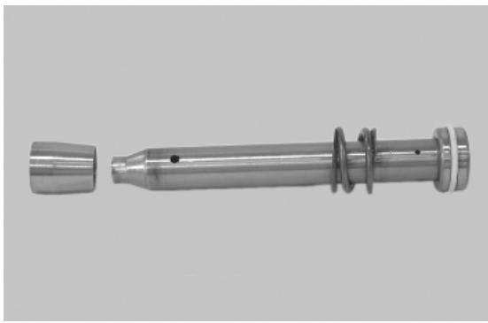
- Check that the main spring exhibits no signs of yielding or abnormal wear.
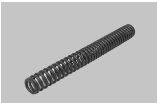
- Check that the closing cap O-ring of the stem is in good conditions.
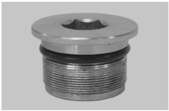
Refitting
- First grease the splitting chamber of the two sealing lips of a new oil seal.
- Fit the sealing ring on the stem and keep the identification words facing upwards.
- Drive the oil seal as far as it will go using the appropriate tool.
020376Y Adaptor handle
020359Y 42x47-mm adaptor
- Pre-fit the stem with the hydraulic rod, the spring and the stop bushing.
- Fit the pre-assembled components inside the fork leg.
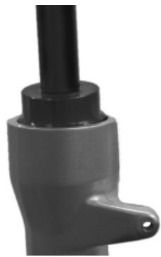
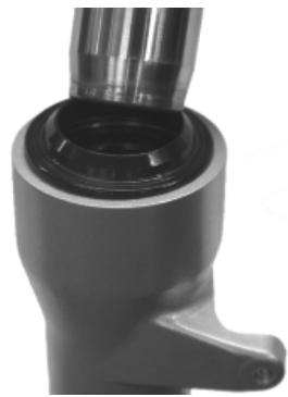
- Fit the hydraulic rod fixing screw with the copper sealing washer and tighten to the prescribed torque using the recommended product.
CAUTION
ALWAYS USE NEW COPPER WASHER.
Locking torques (N^*m)
Hydraulic rod fixing screw 25 ÷ 35^*
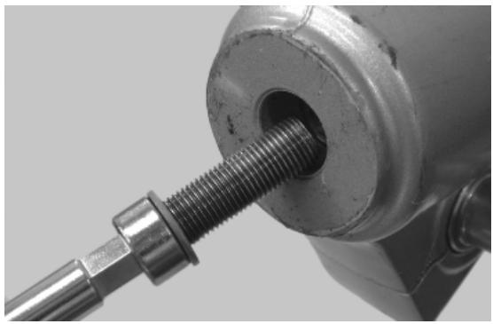
(°) Apply LOCTITE 243 threadlock
- Lock hydraulic rod rotation using a 19-mm hexagonal spanner.
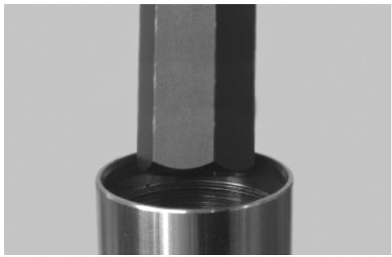
- Fit the oil seal retaining circlip.
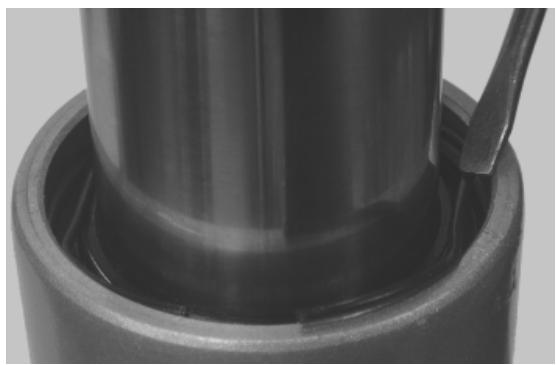
- Grease and fit a new dust guard.
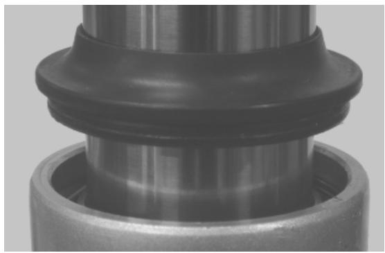
- Fit the fork leg together with the stem on the fork supporting clamp until it stops.
- Tighten the two screws to the prescribed torque in the sequence indicated in the photograph.
Locking torques (N^*m)
Stem support clamp tightening screws 20 ÷ 25
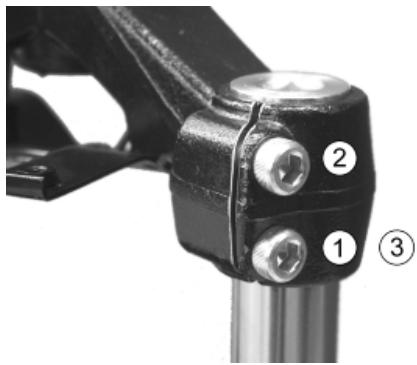
- Refill the fork leg with the recommended product to the prescribed amount.
Recommended products
AGIP FORK 7.5 W Oil for front fork
Hydraulic fluid SAE 7.5 W
Characteristic
Oil quantity per stem
133± 3~cm^3
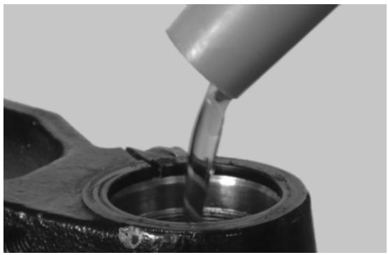
- Bleed the hydraulic rod by actuating the stem repeatedly.
- Fit the spring into the stem.
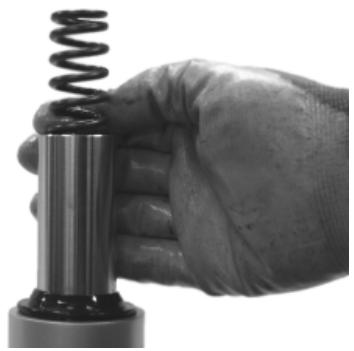
- Lubricate the stem closing cap O-ring.
- Preload the spring, fit the closing cap and tighten to the prescribed torque.
Locking torques (N^*m)
Fork locking screws cap 15 ÷ 30
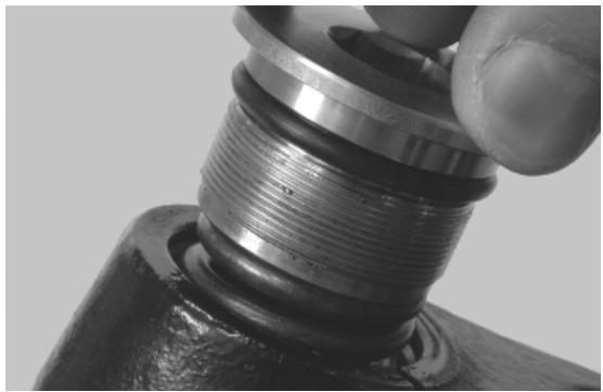
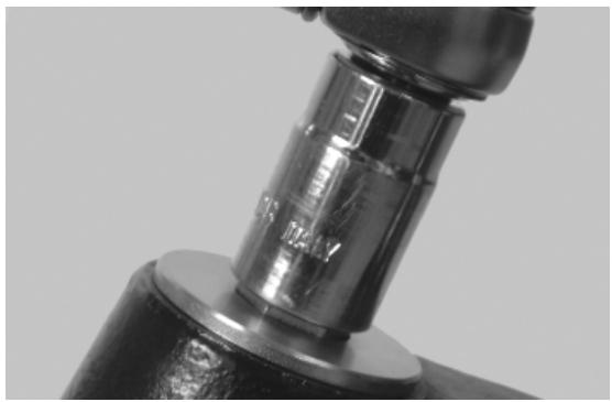
- Repeat the procedure for the other fork leg.
N.B.
IF BOTH FORK LEGS ARE SERVICED AT THE SAME TIME, BE CAREFUL NOT TO INVERT THE RIGHT FORK LEG WITH THE LEFT ONE.
Steering column
Removal
- Remove the front wheel.
- Remove the handlebar and tip it onto the shield back plate being careful not to damage the plate.
- Release the front brake pipe from the fork by undoing the screws indicated.
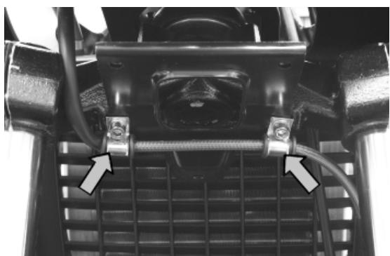
- Using the appropriate tool, loosen and remove the upper ring nut, the space washer, the counter ring nut and the spacer ring.
- Extract the fork.
N.B.
TAKE CARE TO SUPPORT THE FORK SO AS TO PREVENT IT FROM COMING OFF ABRUPTLY
Specific tooling
020055Y Wrench for steering tube ring nut
See also
Removing the front wheel
Removal
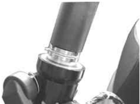
Refitting
- Fit the lower steering fifth wheel on the steering tube.
- Fit the fork together with the lower steering fifth wheel on the headstock and hold it so that it does not fall.
N.B.
LUBRICATE THE STEERING FIFTH WHEEL TRACKS WITH RECOMMENDED GREASE BEFORE USE.
Recommended products
AGIP GREASE PV2 Grease for steering bearings, bolt seatings for swinging arms and fay-ing surface of driven pulley spring (only pulley side)
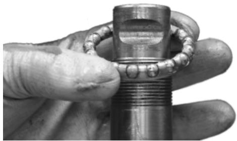
Soap-based lithium and zinc oxide grease containing NLGI 2; ISO-L-XBCIB2
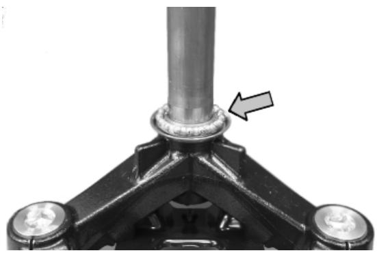
- Fit the upper steering fifth wheel.
CAUTION
INSERT THE UPPER FIFTH WHEEL WITH THE CAGE FACING UPWARDS.
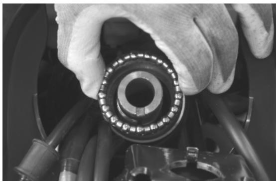
- Fit the steering fifth wheel upper seat.
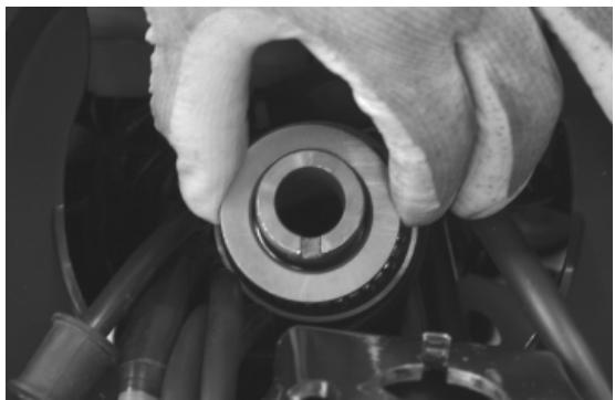
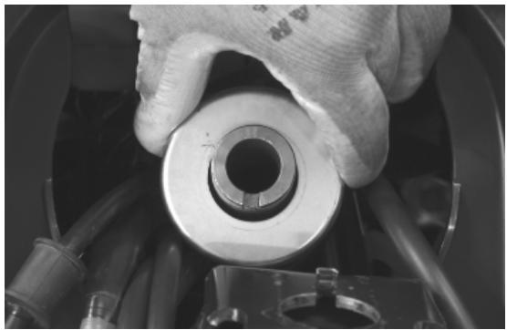
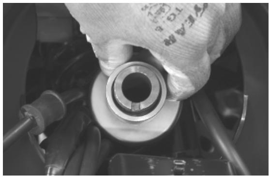
- Insert the lower tightening ring nut, screw until it stops and, with the specific tool, tighten to the prescribed torque.
Specific tooling
020055Y Wrench for steering tube ring nut
Locking torques (N^*m)
Steering tube lower ring nut 14 ÷ 17
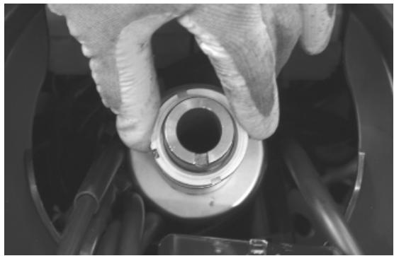
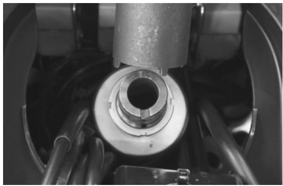
- Fit the spacer between the two ring nuts on the steering tube in the position indicated.
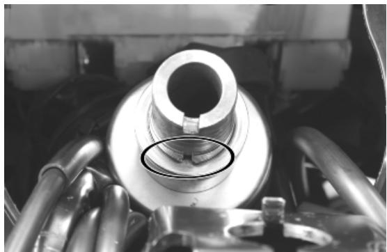
- Insert the upper tightening ring nut, screw until it stops and, with the specific tool, tighten to the indicated torque.
Specific tooling
020055Y Wrench for steering tube ring nut
Locking torques (N^*m)
Steering tube upper ring nut 40 ÷ 45
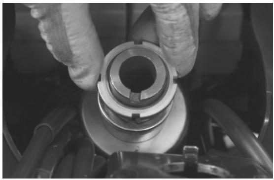
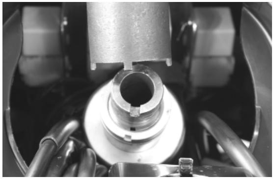
- Fasten the two retainer clamps of the front brake pipe to the fork plate.
Locking torques (N^*m)
Screw fixing the front brake pipe to the fork plate 5 ÷ 7

Steering bearing
Removal
- Clean thoroughly and visually inspect if the components are in good conditions.
- Check the upper steering fifth wheel for wear.
- Check the lower steering fifth wheel for wear.
- Visually inspect that the steering fifth wheel tracks, the headstock and the steering tube exhibit no scores or abnormal wear. Otherwise, replace them.
STEERING FIFTH WHEEL TRACK REMOVAL
- Remove the steering fifth wheel tracks on the chassis with the specific tool, following the indicated procedure.
- Fit the specific tool from the lower part of the headstock until it makes contact with the upper track.
- Hit with force the specific tool, placing it at different points diametrically opposed so as to remove the upper track.
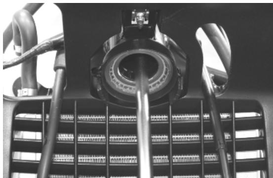
020004Y Punch for removing fifth wheels from headstock

020004Y Punch for removing fifth wheels from headstock
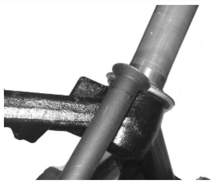
Refitting
STEERING FIFTH WHEEL TRACK FITTING
- Thoroughly clean the track seats on the headstock and the steering tube.
- Fit the new tracks of the headstock with the specific tool.
- Screw the nut until the tracks are fully inserted.
N.B.
LUBRICATE THE STEERING FIFTH WHEEL TRACKS WITH RECOMMENDED GREASE BEFORE USE.
001330Y Tool for fitting steering seats
001330Y014 Tool for fitting steering seats
001330Y015 Tool for fitting steering seats
Recommended products
AGIP GREASE PV2 Grease for steering bearings, bolt seatings for swinging arms and fay-ing surface of driven pulley spring (only pulley side)
Soap-based lithium and zinc oxide grease containing NLGI 2; ISO-L-XBCIB2
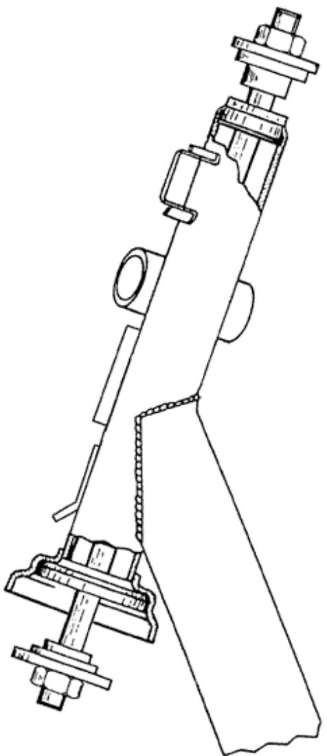
- Fit the lower fifth wheel seat on the steering tube.
- With a tube of the indicated sizes, fit the lower seat until it stops. Inside Ø: 35.5 mm; Outside Ø: 38 mm; Length: 350 mm.
N.B.
LUBRICATE THE STEERING FIFTH WHEEL TRACKS WITH RECOMMENDED GREASE BEFORE USE.
Recommended products
AGIP GREASE PV2 Grease for steering bearings, bolt seatings for swinging arms and fay-ing surface of driven pulley spring (only pulley side)
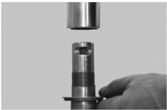
Soap-based lithium and zinc oxide grease containing NLGI 2; ISO-L-XBCIB2
Rear
Removing the rear wheel
- Remove the muffler supporting bracket.
- Remove the rear mudguard.
- Remove the tapered spacer.
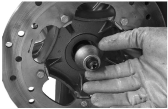
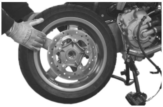
Refitting the rear wheel
To fit, follow the removal steps but in the reverse sequence, being careful to fit the spacers on the wheel axle as shown in the photograph.
Locking torques (N^*m)
Muffler arm clamping screws 27 ÷ 30 Rear wheel axle nut 104 ÷ 126 Shock absorbercrankcase attachment bracket 20 ÷ 25 Lower shock absorber clamping screw 33 ÷ 41 Nm Rear brake calliper fixing screws 25 ÷ 30 Nm
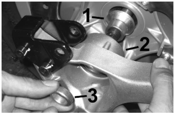
Swing-arm
Removal
- Place the scooter on its centre stand;
- Remove the swinging arm/engine fitting shown in the photo
- Move the engine back
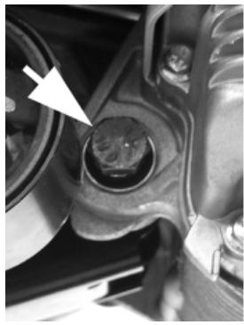
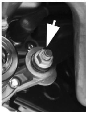
- remove the spring anchoring the swinging arm to the frame as shown in the photo
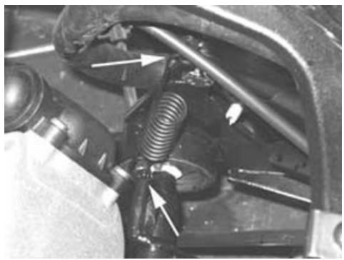
- Remove the two screws fixing the buffer support bracket to the frame
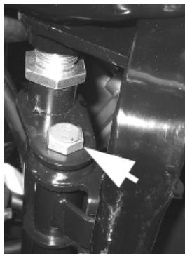
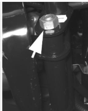
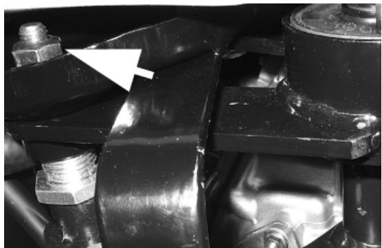
- Check the entire swinging arm assembly.
- Check all the centring bushing components and silent block rubber buffers.
- Replace the work components that cause excessive clearance on the rear suspension.
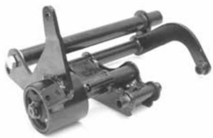
Overhaul
- Check there is no sticking in the movement of the connection of the swinging arm on the engine side to the swinging arm on the frame side.
- Check the axial clearance between the two swinging arms using a feeler gauge
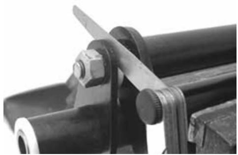
Characteristic
Standard clearance
0.40 ÷ 0.60 ~mm
Allowable limit after use:
1.5 mm
- To check the clearance on the frame-side arm, mount the retainer using the pin fixing the swinging arm to the frame and two adaptor rings of the appropriate tool 020229Y. Alternatively use two washers with inner diameter for 12-mm pins, min. outer diameter: 30 mm: min. thickness: 4 mm.
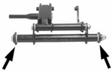
- Check there is no sticking in the rotation.
- Check the axial clearance of the swinging arm on the frame side
Characteristic
Standard clearance
0.40 ÷ 0.60 ~mm
Allowable limit after use:
1.5 mm
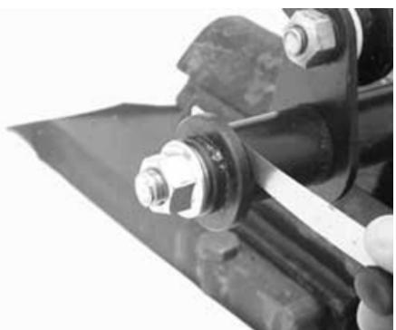
- Separate the swinging arm on the engine side from the vehicle side arm.
- Remove the plastic bushings and the internal spacer shown in the photo.
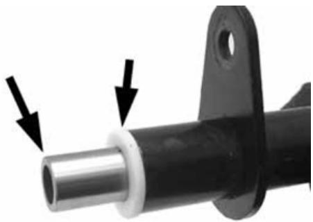
- Using a suitable pin remove the roller casings as shown in the photographs
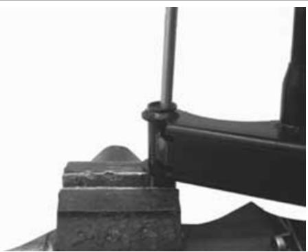
- Using an appropriate tool plant new roller casings, being careful to position the bearings with the O-rings facing outwards
020244Y 15-mm diameter punch
020115Y 0 18 punch
Characteristic
Length of the swinging arm tube on the engine side:
175.3 ± 0.3 ~mm
Length of the internal swinging arm spacer on the engine side:
183± 0.3mm
Engine side swinging arm plastic bushing shim:
3.5 ± 0.05 ~mm
Frame-side swinging arm plastic bushing shim:
3.5 ± 0.05 ~mm
Length of the internal swinging arm spacer on the frame side:
290 ± 0.1 ~mm
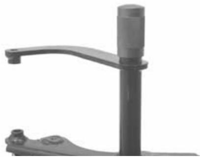
Length of the swinging arm tube on the frame side:
283± 0.1mm
- Lubricate roller casings and the plastic bushings with grease
- Insert the spacers
- Assemble the two arms with the relative bolt in the position shown in the photograph
- Adjust the bolt as shown in the photograph
- Position the frame side swinging arm with the most protruding part pointing towards the silent block side as shown in the photograph
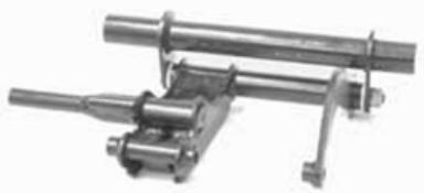
Recommended products
AGIP GREASE PV2 Grease for the steering bearings, pin seats and swinging arm
Soap-based lithium and zinc oxide grease containing NLGI 2; ISO-L-XBCIB2 of the swinging arm
- Make sure the silent bloc is not broken. If there is, replace it.
- Remove the seeger ring shown in the photograph
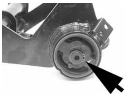
- Remove the full silent bloc bracket
- Undo the silent bloc ring shown in the photograph
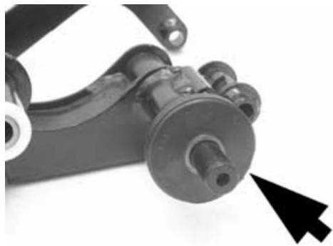
- Hold the full silent bloc bracket in the clamp
- Using the appropriate tool, remove the silent bloc from the bracket from the side corresponding to the inside of the vehicle. This is to guarantee the tool is centred properly on the support
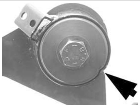
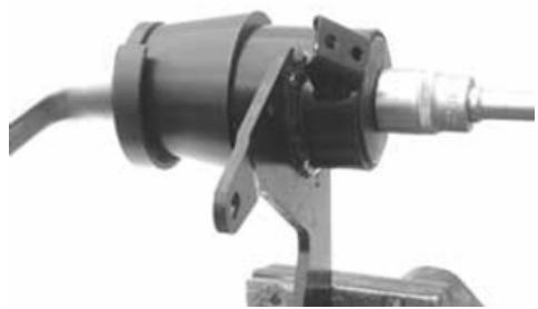
- Install a new silent bloc, making sure it aligns properly with the reference tooth.
- Fit the silent blocs, making sure the chamfered part of the silent bloc matches the chamfered part of the bracket
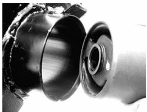
- Using the appropriate tool, fit the silent bloc as shown in the photo
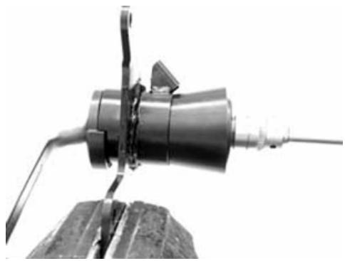
Refitting
Locking torques (N^*m)
Engine and vehicle side swinging arm junction bolt 33 ÷ 41 Nm Swinging arm pin - Engine 64 - 72 Body shell - Swinging arm pin 76 ÷ 83 Screw fixing the silent-block support plate to the body 42 ÷ 52
Shock absorbers
Removal
- Rest the scooter on its centre stand.
- Slightly lift the engine using a jack to free both shock absorbers.
- Remove the silencer.
- Unscrew the shock absorber spring unit fixing screw from the support fixed to the engine on one side, and from that fixed to the muffler support on the other.
- Undo the two upper nuts (one on each side) fixing the shock absorber spring unit to the frame and remove the shock absorbers themselves.
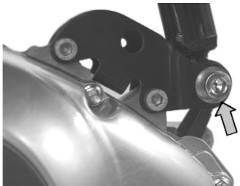
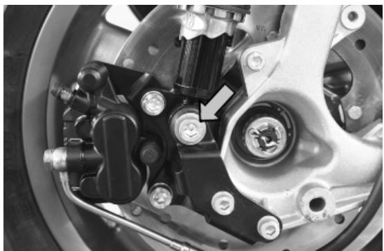
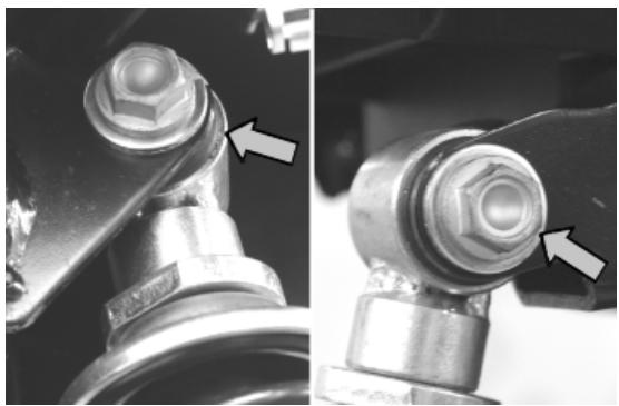
Refitting
Carry out the previous operations but in reverse order.
Locking torques (N^*m)
Shock absorber lower clamp 33 ÷ 41 Upper shock absorber clamp 33 ÷ 41
Exhaust bracket
Removal
- Remove the exhaust silencer.
- Remove the rear brake calliper, release the rear brake pipes from the retainer clamp and undo the screw fixing the rear mudguard.
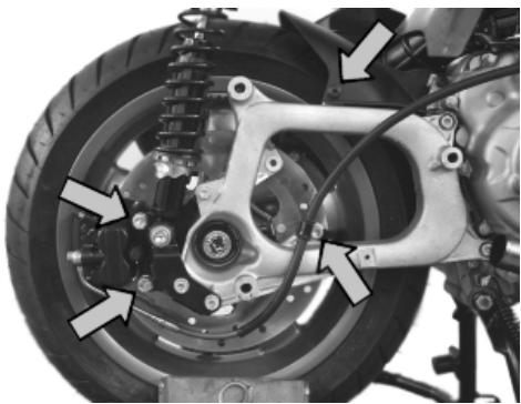
- Release the cotter pin and remove the cap.
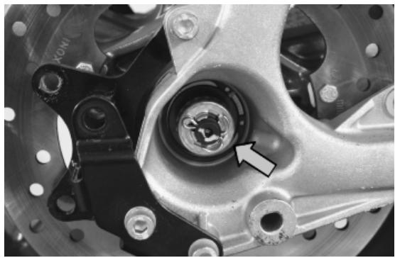
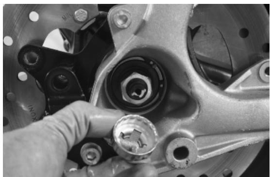
- Unscrew the rear wheel fixing nut and remove the spacer.
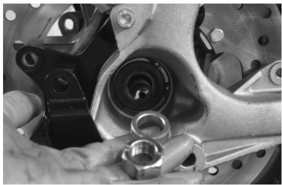
- Undo the two fixing screws to the engine crank-case.
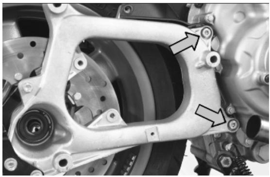
- Remove the muffler supporting bracket.
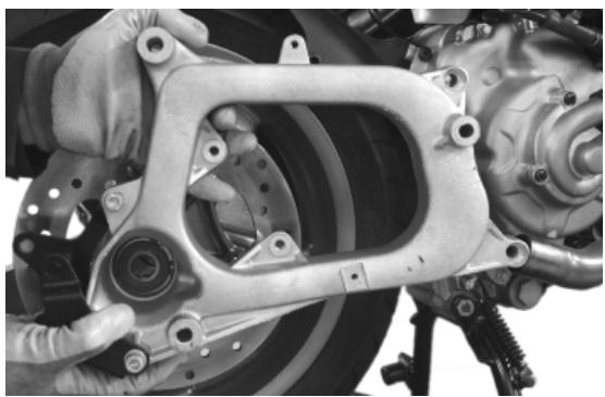
Overhaul

- With the appropriate tools, remove the bearing from the inside.
Specific tooling
020376Y Adaptor handle
020439Y 17 mm guide
020358Y 37x40-mm adaptor
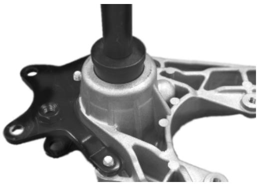
- Check that the bearing seat is not abnormally worn.
- Heat the bearing seat with the appropriate tool.
020151Y Air heater
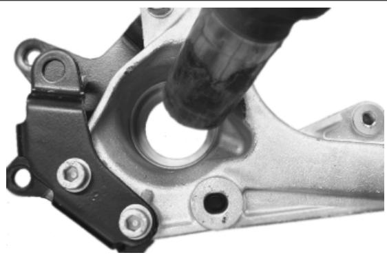
- Drive a new bearing as far as it will go using the appropriate tool.
020376Y Adaptor handle
020439Y 17 mm guide
020359Y 42x47-mm adaptor
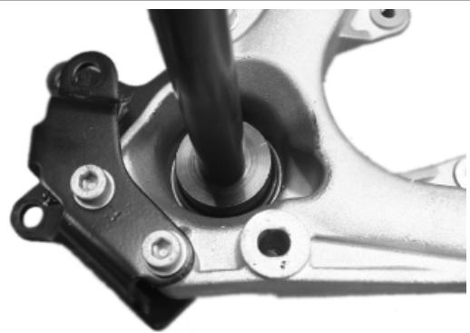
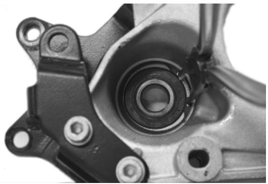
Refitting
- Follow the removal procedures but in reverse order and tighten to the prescribed torques.
- Lubricate the rear wheel axle with the recommended product.
Recommended products
AGIP GREASE PV2 Grease for steering bearings and spindle seats
Soap-based lithium and zinc oxide grease containing NLGI 2; ISO-L-XBCIB2 of the swinging arm
Locking torques (N^*m)
Muffler arm clamping screws 27 ÷ 30 Rear wheel axle 104 ÷ 126
See also
Refitting
Refitting the rear wheel
Refitting
Centre-stand
REMOVAL
- Use a jack to support the vehicle properly.
- Remove the two stand return springs.
- Undo the nut shown in the figure.
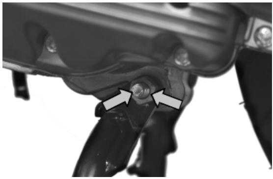
- Remove the bolt from the right side.
- Remove the centre stand.
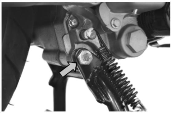
FITTING
- Install the sealing rings on the support tube of the stand;
- Carry out the operations described above in reverse order, then insert the sealing rings into their seats.
CAUTION
LUBRICATE THE FOLLOWING PARTS WITH GREASE: SPRING COUPLING PINS, BUSHINGS ON STAND FIXING BRACKETS.
Recommended products
AGIP GREASE PV2 Grease for control levers on the engine
White anhydrous-calcium based grease to protect roller bearings; temperature range between -20 °
C and +120 °C; NLGI 2; ISO-L-XBCIB2
Locking torques (N^*m)
Stand fixing bolt 40 ÷ 45
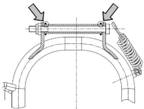
Side stand
REMOVAL
- Uncouple the centre stand return spring;
Remove the screw shown in the photograph
FITTING
To refit, carry out the removal operations in reverse order and comply with the specified torque.
Locking torques (N^*m)
Side stand fixing bolt 35 ÷ 40
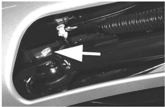
INDEX OF TOPICS
BRAKING SYSTEM
BRAK SYS
This section is devoted to the description of the braking system components.
Rear brake calliper
Removal
- Remove the muffler.
- Remove the two rear brake calliper devices fastening them to the support as shown in the photograph.
N.B.
SHOULD THE BRAKE CALLIPER BE REPLACED, BEFORE REMOving THE FITTINGS FIXING THE CALLIPER TO THE SUPPORTING BRACKET, FIRST LOOSEN THE OIL HOSE FITTING AFTER HAVING EMPTIED THE SYSTEM OF THE CIRCUIT BEING INSPECTED.
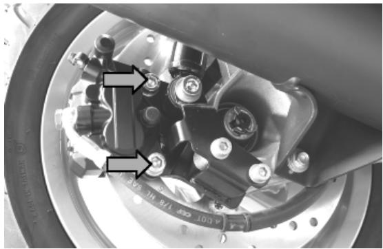
Refitting
- Follow the removal procedures but in reverse order and tighten to the prescribed torques with the recommended product.
Recommended products
Loctite 243 Medium strength threadlock
Loctite 243 medium-strength threadlock
Locking torques (N^*m)
Screw tightening calliper to the support 42 ÷ 52
If the calliper is replaced:
CAUTION
ONCE REFITTING IS FINISHED, BLEED THE SYSTEM.
CAUTION
ALWAYS USE NEW COPPER WASHERS.
Locking torques (N^*m)
Rear brake calliper-pipe fitting 20 ÷ 25
See also
Rear - combined
Front brake calliper
Removal
- Remove the two retainers fastening the front brake calliper to the support as shown in the photograph.
N.B.
SHOULD IT BE NECESSARY TO REPLACE THE CALLIPER, FIRST LOOSEN THE FITTING CONNECTING THE PIPE TO THE BRAKE CALLIPER.
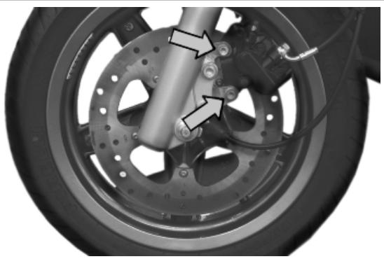
Refitting
- To fit the calliper, follow the above operations but in reverse order.
Locking torques (N^*m)
Screw tightening calliper to the support 24 ÷ 27
If the caller is replaced:
CAUTION
ALWAYS USE NEW COPPER WASHERS.
CAUTION
ONCE REFITTING IS FINISHED, BLEED THE SYSTEM.
Locking torques (N^*m)
Brake fluid pipe-calliper fitting 20 ÷ 25
See also
Front
Rear brake disc
Removal
- Remove the rear wheel.
- Act on the disc five fixing screws shown in the photograph.
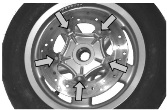
Refitting
For fitting, position the disc correctly using the arrow stamped on it as reference.
N.B.
THE ARROW STAMPED ON THE DISC INDICATING THE RUNNING DIRECTION MUST BE FITTED TOWARDS THE OUTSIDE OF THE VEHICLE.
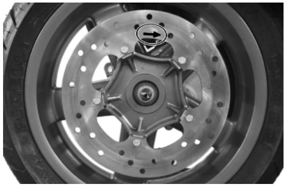
- Tighten the screws to the prescribed torque and apply the recommended product.
Recommended products
Loctite 243 Medium strength threadlock
Loctite 243 medium-strength threadlock
Locking torques (N^*m)
Brake disc screws 8 ÷ 10
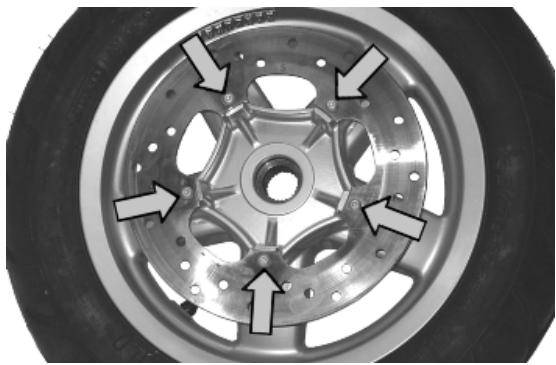
Disc Inspection
- Remove the rear brake calliper
- Check disc thickness with a micrometer, repeat the measurement at no fewer than six points on the disc.
Characteristic
Standard thickness:
$$
5 \pm 0. 2 \mathrm {m m}
$$
Disc thickness at wear limit
4.5 mm
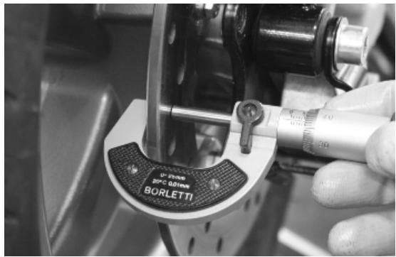
-
Check the brake disc rotates regularly using the appropriate tool fixed onto the brake calliper support.
-
In order to be able to anchor the specific tool properly use a metal plate with an M8 threaded hole and fix it to one of the two rear brake calliper attachment points.
N.B.
SO AS NOT TO GET A DISTORTED READING, CAUSE THE DRIVEN PULLEY SHAFT TO TURN IN ORDER TO ROTATE THE DISC.
020335Y Magnetic support for dial gauge
Characteristic
Max. deviation allowed:
0.1 mm
- If you detect incorrect values, replace the disc.
- If the fault continues, repeat the test.
- If the problem persists, replace the wheel.
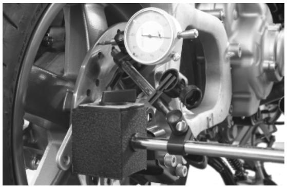
Front brake disc
Removal
- Remove the front wheel.
- Undo the five clamping screws shown in the photograph
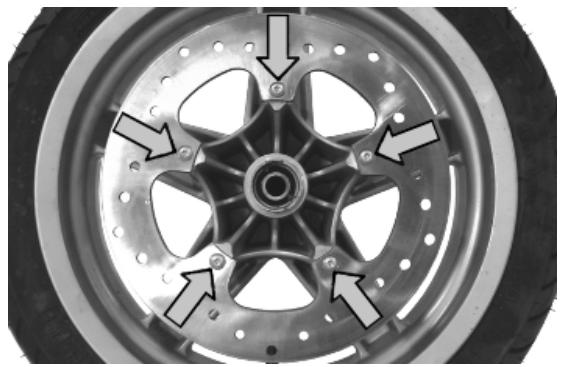
Refitting
For fitting, position the disc correctly using the arrow stamped on it as reference.
N.B.
THE ARROW STAMPED ON THE DISC INDICATING THE RUNNING DIRECTION MUST BE FITTED TOWARDS THE OUTSIDE OF THE VEHICLE.
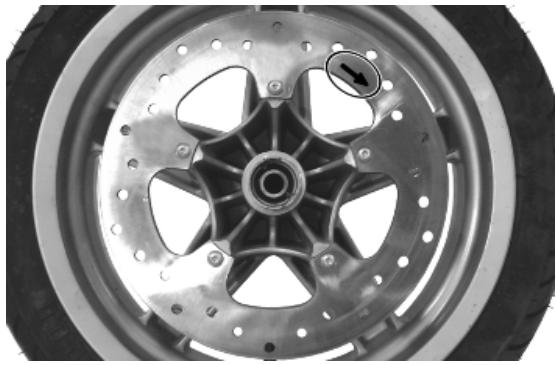
- Tighten the screws to the prescribed torque and apply the recommended product.
Recommended products
Loctite 243 Medium strength threadlock
Loctite 243 medium-strength threadlock
Locking torques (N^*m)
Brake disc screws 8 ÷ 10
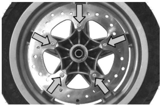
Disc Inspection
- Remove the front calliper.
- Check disc thickness with a micrometer, repeat the measurement at no fewer than six points on the disc.
Characteristic
Standard thickness:
$$
5 \pm 0. 2 \mathrm {m m}
$$
Disc thickness at wear limit
4.5 mm
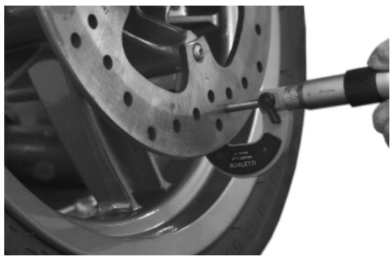
-
Check the brake disc rotates regularly using the appropriate tool fixed onto the brake calliper support.
-
In order to secure the specific tool adequately use a metal plate with an M8 threaded hole and fix it to one of the two front brake calliper attachment points.
020335Y Magnetic support for dial gauge
Characteristic
Max. deviation allowed:
0.1 mm
- If you detect incorrect values, replace the disc.
- If the fault continues, repeat the test.
- If the problem persists, replace the wheel.
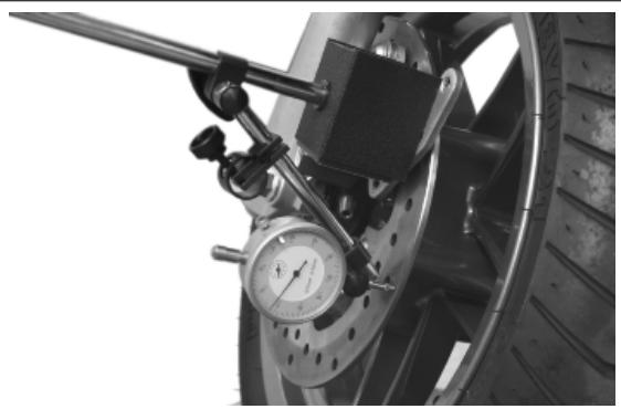
Front brake pads
Removal
Proceed as follows:
- Remove the front calliper.
- Loosen the two pins shown in the figure that lock the two pads.
- Remove the pads, being careful with the pad spring clamp.
- Check the thickness of the friction material of the pads.
- Replace the pads if the thickness is below the minimum value.
- The replacement must be made with greater residual thickness if the pad has not worn evenly. A 0.5 ~mm thickness difference in the residual friction material is permitted.
Characteristic
Minimum value
1.5 mm
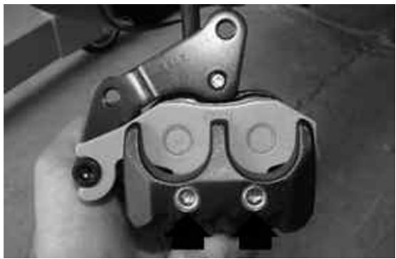
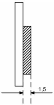
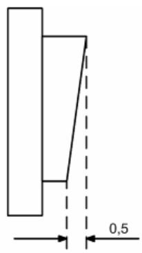
See also
Front brake calliper
Refitting
To fit, proceed as follows:
- Insert the two pads in the callipers.
- Screw the two pad lock pins to the correct torque, and apply the recommended product.
- Fit the calliper on its support, tightening the two screws to the prescribed torque.
N.B.
IF IT IS NOT POSSIBLE TO CORRECTLY POSITION THE CALLIPER ON THE DISC DURING FITTING, GENTLY EXPAND THE PADS.
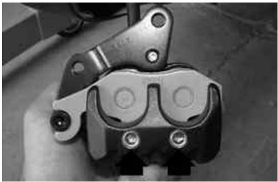
Recommended products
Loctite 243 Medium strength threadlock
Loctite 243 medium-strength threadlock
Locking torques (N^*m)
Screw tightening calliper to the support 24 ÷ 27 Pad fastening pin 19.6 ÷ 24.5
Rear brake pads
Removal
- Remove the rear brake calliper
- Loosen the two pins shown in the figure that lock the two pads; be careful with the pad spring clamp.
- Remove the brake pad and check there are no faults or warping. Replace it if such anomalies are present.
- Check the thickness of the friction material is more than 1.5 ~mm . If it is not, replace it
- The replacement must be made with greater residual thickness if the pad has not worn evenly. A 0.5 ~mm thickness difference in the residual friction material is permitted.
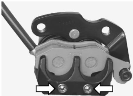
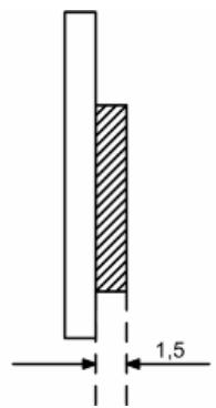
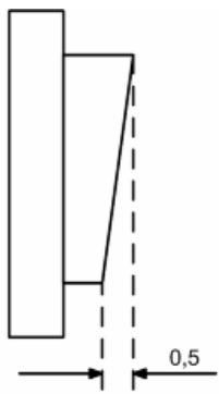
See also
Rear brake calliper
Refitting
To fit, proceed as follows:
- Insert the two pads in the callipers.
- Screw the two pad lock pins to the correct torque, and apply the recommended product.
- Fit the calliper on its support, tightening the two screws to the prescribed torque.
N.B.
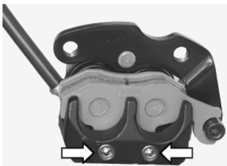
IF IT IS NOT POSSIBLE TO CORRECTLY POSITION THE CALLIPER ON THE DISC DURING FITTING, GENTLY EXPAND THE PADS.
Recommended products
Loctite 243 Medium strength threadlock
Loctite 243 medium-strength threadlock
Locking torques (N^*m)
Screw tightening calliper to the support 24 ÷
27 Pad fastening pin 19.6 ÷ 24.5
Fill
Rear - combined
- Remove the rubber hood from the bleed screw.
- Insert a rubber pipe in the bleed screw to permit the brake fluid to be recovered.
- With the brake lever, load the system and bring it up to the required pressure.
- Keeping the brake lever pulled, loosen the bleed screw to purge the air in the system. Then tighten the bleed screw
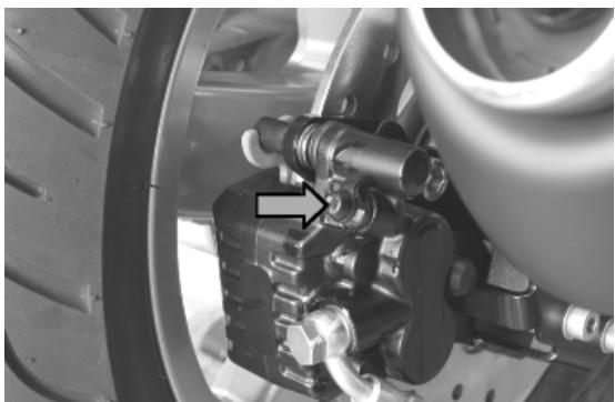
- Repeat the operation until only brake fluid comes out of the rubber pipe.
- Remove the fluid recovery pipe and refit the rubber cap over the bleed screw.
- Top up the brake fluid to the right level in the reservoir.
If necessary, bleeding can be done using a special vacuum pump
N.B.
DURING THE BLEEDING OPERATIONS, MAKE SURE THE BRAKE FLUID DOES NOT COME INTO CONTACT WITH THE BODYWORK SO AS NOT TO DAMAGE IT. FURTHERMORE, DURING THE BLEEDING OPERATIONS REGARDING THE BRAKE CALLIPERS, MAKE SURE THE BRAKE FLUID DOES NOT COME INTO CONTACT WITH THE DISC BRAKES AND WITH THE BRAKE PADS. FAILURE TO COMPLY WITH THIS NORM WILL ENDANGER THE PROPER WORKING AND EFFICIENCY OF THE BRAKING SYSTEM
Specific tooling
020329Y MityVac vacuum-operated pump
Locking torques (N^*m)
System bleed calliper fitting: 12 ÷ 16 Nm
Front
- Remove the rubber hood from the bleed screw.
- Insert a rubber pipe in the bleed screw to permit the brake fluid to be recovered.
- With the brake lever, load the system and bring it up to the required pressure.
- Keeping the brake lever pulled, loosen the bleed screw to purge the air in the system. Then tighten the bleed screw
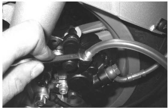
- Repeat the operation until only brake fluid comes out of the rubber pipe.
- Remove the fluid recovery pipe and refit the rubber cap over the bleed screw.
- Top up the brake fluid to the right level in the reservoir.
If necessary, bleeding can be done using a special vacuum pump
N.B.
DURING THE BLEEDING OPERATIONS, MAKE SURE THE BRAKE FLUID DOES NOT COME INTO CONTACT WITH THE BODYWORK SO AS NOT TO DAMAGE IT. FURTHERMORE, DURING THE BLEEDING OPERATIONS REGARDING THE BRAKE CALLIPERS, MAKE SURE THE BRAKE FLUID DOES NOT COME INTO CONTACT WITH THE DISC BRAKES AND WITH THE BRAKE PADS. FAILURE TO COMPLY WITH THIS NORM WILL ENDANGER THE PROPER WORKING AND EFFICIENCY OF THE BRAKING SYSTEM
Specific tooling
020329Y MityVac vacuum-operated pump
Locking torques (N^*m)
System bleed calliper fitting: 12 ÷ 16 Nm
Brake fluid level check
The front and rear brake fluid reservoirs are both positioned on the handlebars. Proceed as follows:
- Rest the vehicle onto the centre stand, with the handlebar centred.
- Check the fluid level through the sight glass «A».
A certain lowering of the level is caused by wear on the pads.
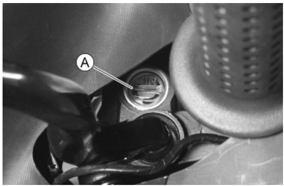
Front brake pump
Removal
- Remove the front and rear handlebar cover.
- Place a suitable container to collect the oil, disconnect the oil pipe from the calliper and operate the brake lever until no more oil comes out.
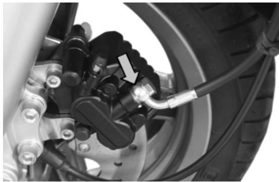
- Disconnect the oil pipe from the pump.
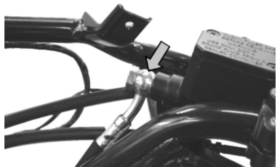
- Unscrew the two clamps of the U-bolt and remove the pump.
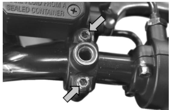
Refitting
- Upon refitting, perform the operation but in reverse order.
- Tighten the hydraulic line to the prescribed torque and purge the system.
- When the operation is over, tighten the brake fluid bleed screw to the prescribed torque.
WARNING
THE BRAKE FLUID IS HYGROSCOPIC, THAT IS, IT ABSORBS MOISTURE FROM THE SURROUNDING AIR. IF THE LEVEL OF MOISTURE IN THE FLUID EXCEEDS A GIVEN VALUE, BRAKING EFFICIENCY WILL BE REDUCED. THEREFORE, ALWAYS USE FLUID FROM SEATED CONTAINERS. UNDER NORMAL DRIVING AND CLIMATIC CONDITIONS YOU SHOULD CHANGE THIS LIQUID EVERY TWO YEARS. IF THE BRAKES ARE USED INTENSELY AND/OR IN HARSH CONDITIONS, CHANGE THE FLUID MORE FREQUENTLY.
CAUTION
WHEN CARRYING OUT THE OPERATION, BRAKE FLUID MAY LEAK FROM BETWEEN THE BLEED SCREW AND ITS SEAT ON THE CALLIPER. CAREFULLY DRY THE CALLIPER AND DEGREASE THE DISC SHOULD THERE BE BRAKE FLUID ON IT.
CAUTION
ALWAYS USE NEW COPPER WASHERS.
Locking torques (N^*m)
Oil bleed screw 12 - 16 Rear brake calliper-pipe fitting 20 ÷ 25 Rear brake pump-pipe fitting 16 ÷ 20 Fixing screws for handlebar control assembly U-bolts 7 ÷ 10
See also
Front
Rear brake pump - combined
Removal
- Remove the front and rear handlebar cover.
- Place a suitable container to collect the oil, disconnect the oil pipe from the calliper and operate the brake lever until no more oil comes out.
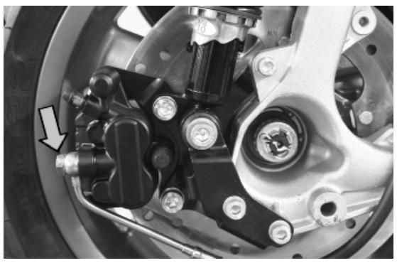
- Disconnect the oil pipe from the pump.
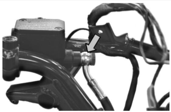
- Unscrew the two clamps of the U-bolt and remove the pump.
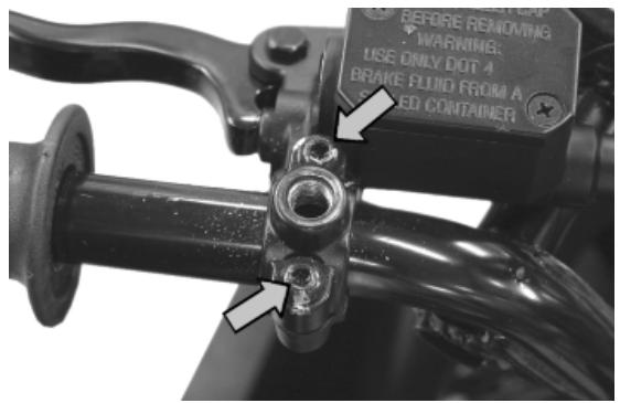
Refitting
- Upon refitting, perform the operation but in reverse order.
- Tighten the hydraulic line to the prescribed torque and purge the system.
- When the operation is over, tighten the brake fluid bleed screw to the prescribed torque.
WARNING
THE BRAKE FLUID IS HYGROSCOPIC, THAT IS, IT ABSORBS MOISTURE FROM THE SURROUNDING AIR. IF THE LEVEL OF MOISTURE IN THE FLUID EXCEEDS A GIVEN VALUE, BRAKING EFFICIENCY WILL BE REDUCED. THEREFORE, ALWAYS USE FLUID FROM SEATED CONTAINERS. UNDER NORMAL DRIVING AND CLIMATIC CONDITIONS YOU SHOULD CHANGE THIS LIQUID EVERY TWO YEARS. IF THE BRAKES ARE USED INTENSELY AND/OR IN HARSH CONDITIONS, CHANGE THE FLUID MORE FREQUENTLY.
CAUTION
WHEN CARRYING OUT THE OPERATION, BRAKE FLUID MAY LEAK FROM BETWEEN THE BLEED SCREW AND ITS SEAT ON THE CALLIPER. CAREFULLY DRY THE CALLIPER AND DEGREEASE THE DISC SHOULD THERE BE BRAKE FLUID ON IT.
CAUTION
ALWAYS USE NEW COPPER WASHERS.
Locking torques (N^*m)
Oil bleed screw 12 - 16 Rear brake calliper-pipe fitting 20 ÷ 25 Rear brake pump-pipe fitting 16 ÷ 20 Fixing screws for handlebar control assembly U-bolts 7 ÷ 10
See also
Rear - combined
INDEX OF TOPICS
COOLING SYSTEM
COOL SYS
Circuit diagram
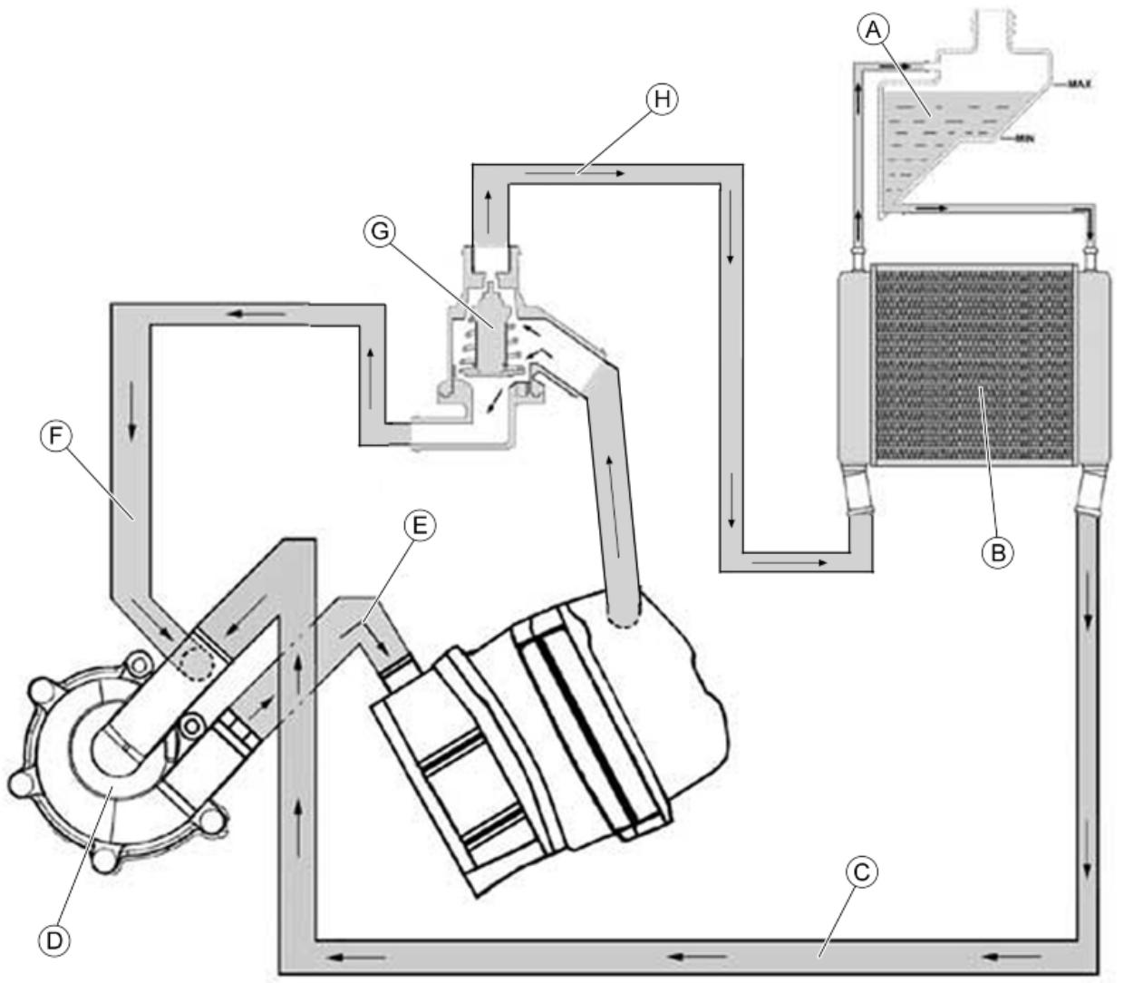
KEY
A = Expansion tank
B = Radiator
C = Radiator intake pipe
D = Water pump
E = Delivery pipe to cylinder
F = By-Pass pipe
G = Thermostat
H = Radiator delivery pipe
Electric fan check
- Check the correct battery voltage and restore, if necessary.
Characteristic
Battery voltage
12V
- Check that the electric ventilation relay is working properly.
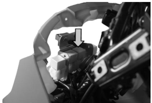
- If the relay is not working, replace it.
- If the relay is working, remove it and jump the red
- red black (85 - 86) wires. The electric ventilation starts if the key switch is set to «ON» and all components are working.
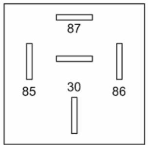
- For checking the coolant temperature sensor, see the «Injection» chapter.
See also
Controllo teleruttori
System bleed
- Start up the engine until the operating temperature is reached.
- Remove the rubber hood over the bleed valve
- Obtain a rubber tube that is of the right length to connect the valve to the expansion tank
- Place one end of the pipe on the bleed valve and the other in the expansion tank
- Loosen the screw by two turns until the communication hole is revealed with the head as shown in the photo
- Wait until only coolant comes out of the rubber pipe so as to eliminate any air bubbles inside the circuit.
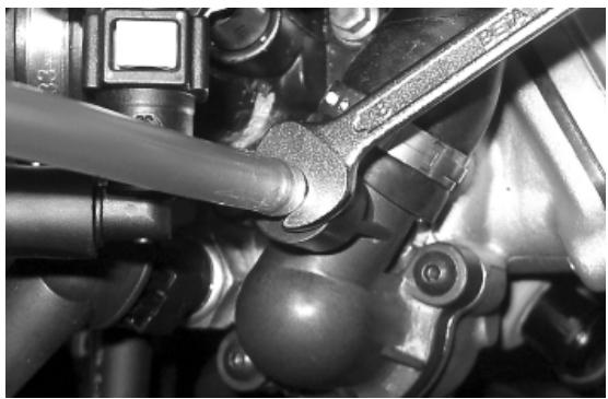
- Tighten the bleed valve respecting the maximum torque.
- Bring the coolant up to the correct level inside the expansion tank
Locking torques (N^*m)
Bleed screw: 3
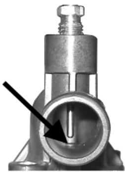
Removal
- Loosen the two screws indicated in the figure and remove the thermostat cover.
- Remove the thermostat with its gasket.
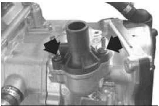
Check
- Visually check that the thermostat is not damaged.
- Prepare a metal container with approx. 1 litre of water.
- Immerse the thermostat, keeping it in the centre of the container.
- Immerse the multimeter temperature probe, near the thermostat.
- Warm up the container using the heat gun.
- Check the temperature when the thermostat starts to open:
- Warm up until the thermostat opens completely.
- Replace the thermostat if it does not work properly.
CAUTION
TO EXECUTE THE TEST CORRECTLY, MAKE SURE NEITHER THE THERMOSTAT NOR THE THERMOMETER TOUCHES THE CONTAINER.
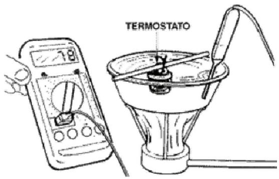
020331Y Digital multimeter
020151Y Air heater
Characteristic
Thermostat check: Opening start temperature
85 ÷ 1.5^ C
Refitting
- Place the thermostat with the bleeding hole at the highest point.
- Make sure that the rubber gasket is positioned properly.
- Fit the thermostat cover with the connection for the carburettor heating pipe facing the flywheel.
- Tighten the two screw to the torque indicated below.
Locking torques (N^*m)
Thermostat cover screws 3 ÷ 4
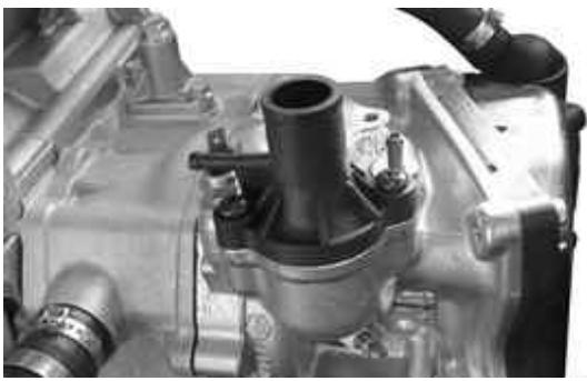
INDEX OF TOPICS
CHASSIS
CHAS
Seat
- Lift the saddle and undo the three screws indicated.
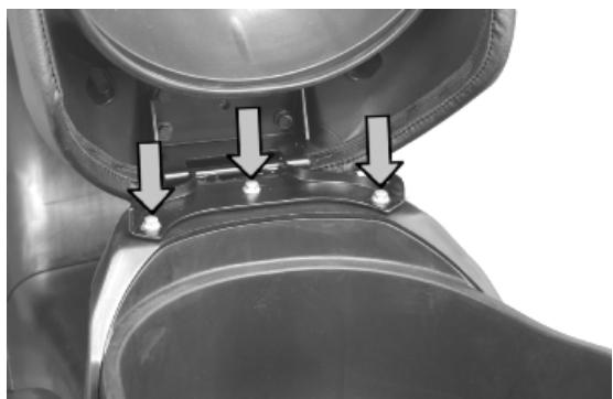
Driving mirrors
- Unscrew the lock-nut and slide off the rear-view mirror stem.
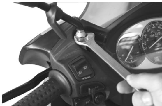
Rear handlebar cover
- Remove the front handlebar cover.
- Undo the two screws indicated.
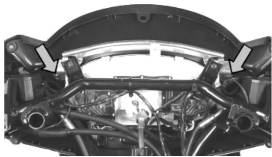
- Undo the two screws and disconnect the connections of the electrical controls.
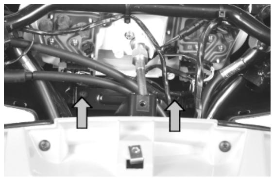
See also
Front handlebar cover
Instrument panel
- Remove the rear handlebar cover.
- Disconnect the odometer transmission cable.
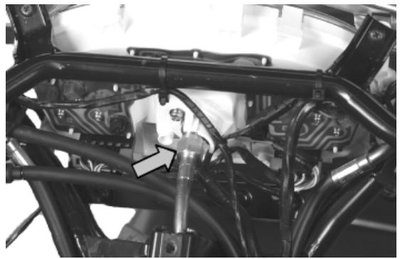
- Undo the two screws indicated.
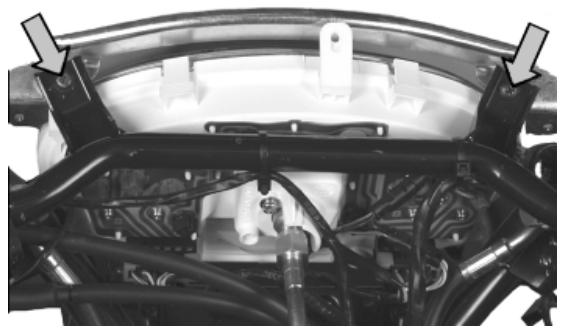
- Undo the two screws indicated and disconnect the connectors.
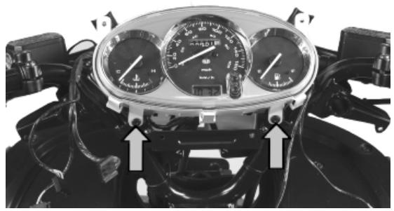
See also
Rear handlebar cover
Front handlebar cover
- Remove the windshield and the front central cover.
- Undo the screw indicated from both sides of the vehicle.
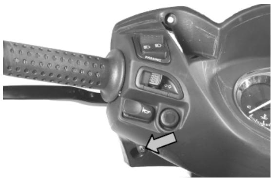
- Undo the screw indicated and remove the front handlebar cover.
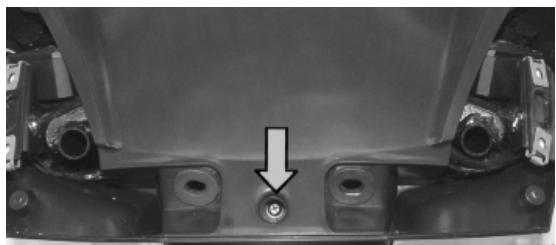
See also
Front central cover
Flyscreen
Headlight assay.
- Remove the front central cover.
- Undo the three screws indicated.
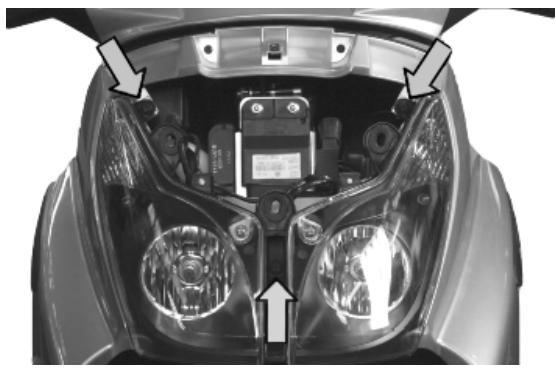
- Undo the screw indicated in the front wheel housing on both sides.
- Disconnect the connectors from the low-beam, high-beam and turn indicators bulbs.
- Slide off the tail light rubber bulb holders.
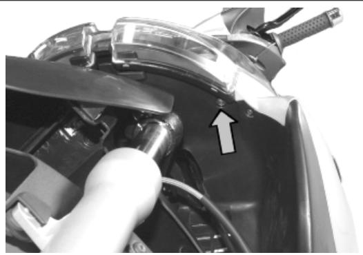
See also
Front central cover
Frame central cover
- Remove the saddle.
- Undo and remove the screw indicated from both sides of the vehicle and free the retainers.
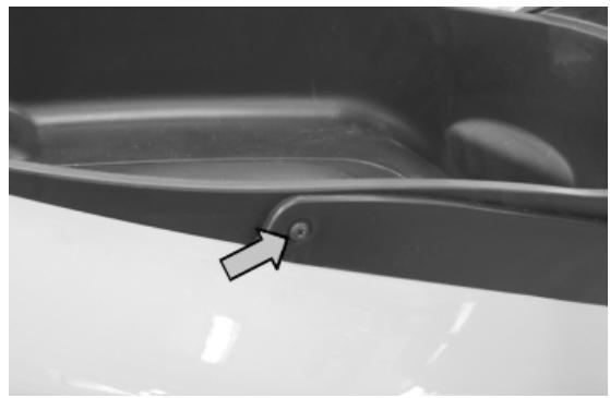
- Unscrew the fuel tank cap.
- Undo the two screws indicated.
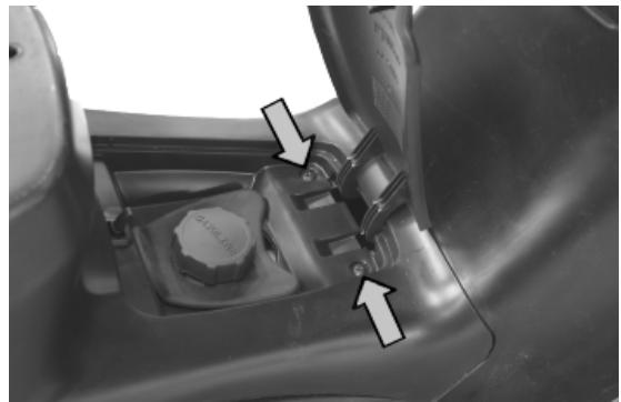
- Free the central cover from its retainers.
- Disconnect the fuel tank cap opening transmission.
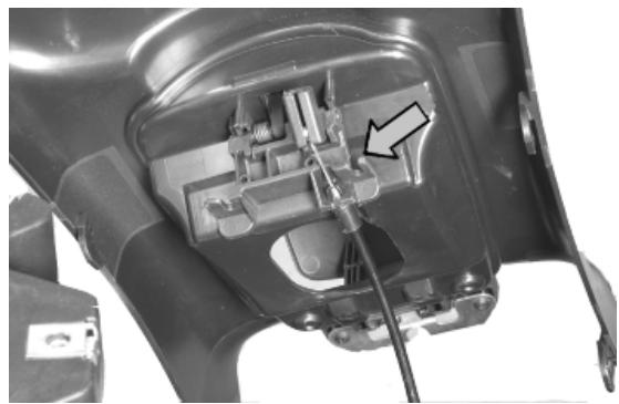
See also
Seat
Legshield
- Remove the shield back plate.
- Remove the headlight assembly.
- Undo the four screws indicated.
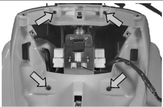
- Undo the screw indicated in the front wheel housing on both sides.
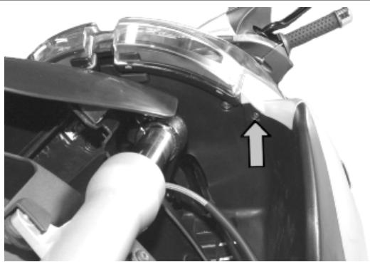
- Undo the two screws indicated on both sides of the vehicle.
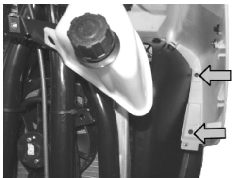
See also
Knee-guard
Headlight assay.
Knee-guard
- Remove the footrest.
- Undo the four screws on both sides.
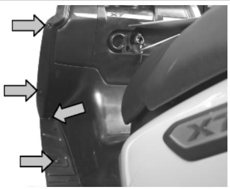
- Undo the screw indicated on both sides of the vehicle.
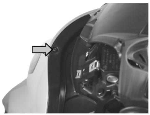
- Undo the screw indicated.
- Remove the lid and unscrew the expansion tank cap.
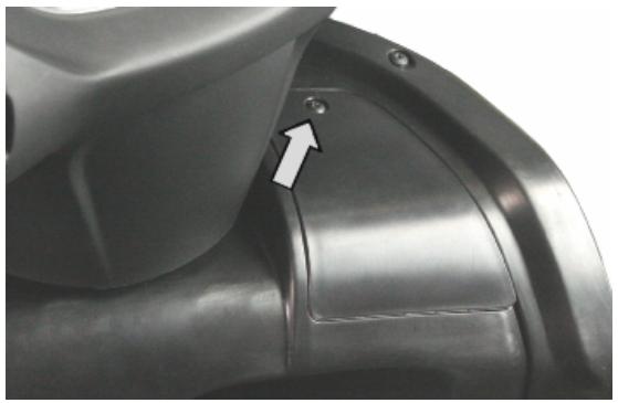
- Undo the screw indicated.
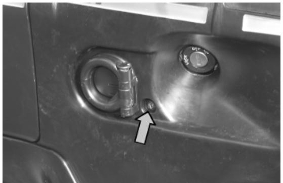
- Undo the screw indicated on both sides of the vehicle.
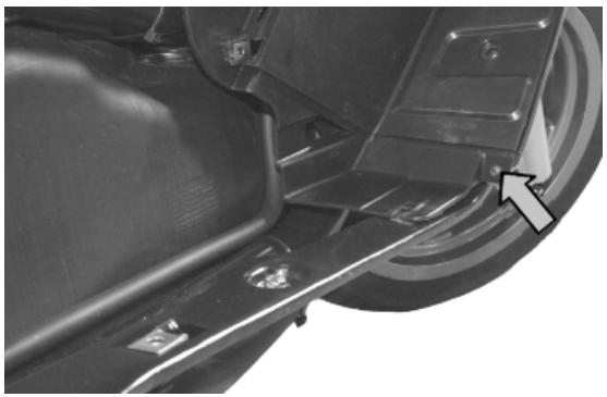
See also
Front wheel housing
- Remove the front shield.
- Remove the fork
- Undo the screw indicated.
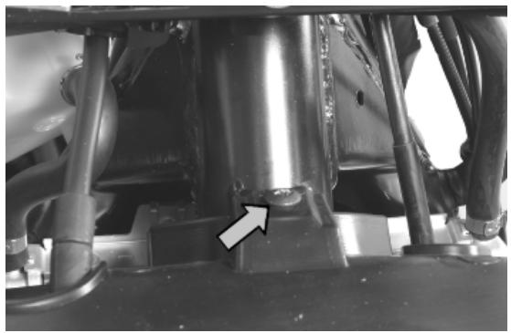
- Undo the screw indicated from both sides of the vehicle.
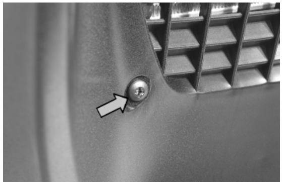
See also
Legshield
Taillight assay.
- Undo the two screws indicated.
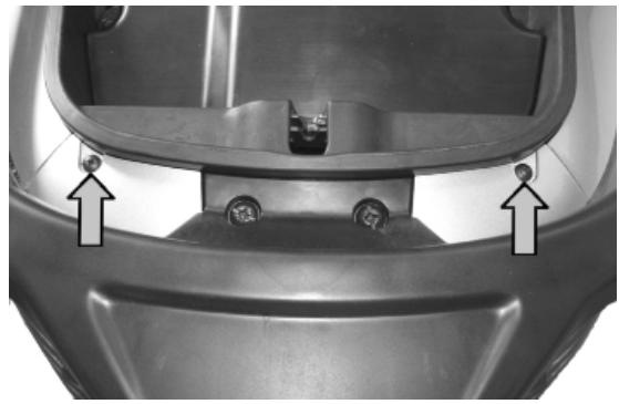
- With the aid of a flat screwdriver, remove the cover indicated.
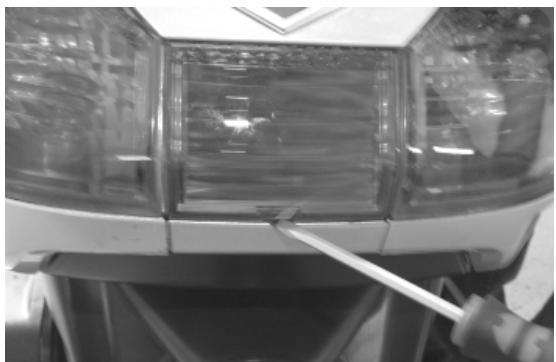
- Undo the two screws indicated.
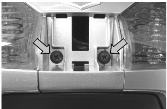
- Extract the light units and disconnect the bulb connectors.
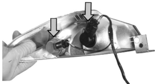
License plate light
- Undo the screw indicated and slide off the rubber bulb holder.
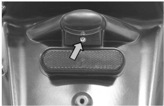
- Remove the rear light unit and disconnect the electrical connection indicated.
See also
Taillight assy.
- Remove the side fairing.
- Undo the three screws indicated.
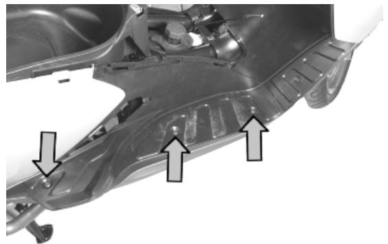
- Remove the two screws indicated in the front wheel housing.
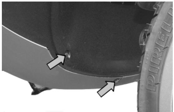
- Undo the two screws indicated.
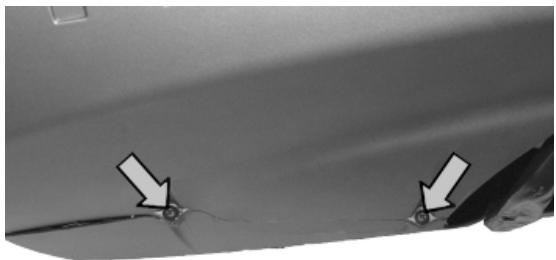
See also
Side fairings
Side fairings
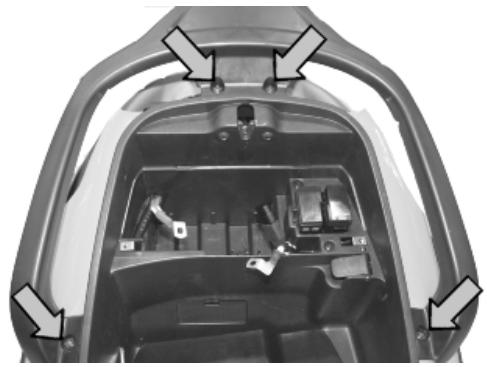
- Undo the two screws indicated.
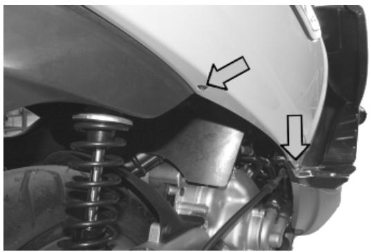
- Undo the screw indicated and remove the inspection door.
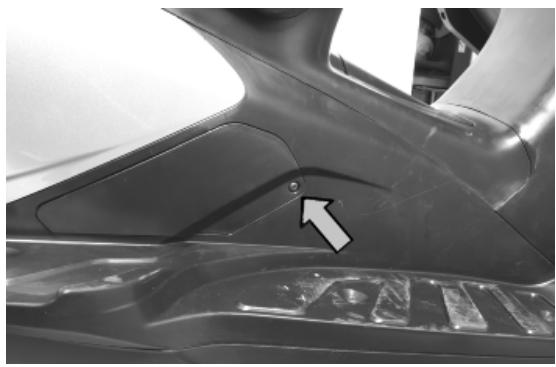
- Undo the two screws indicated.
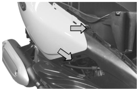
See also
Frame central cover
Taillight assy.
License plate holder
- Remove the side fairings.
- Undo the two screws indicated on both sides of the vehicle.
- Disconnect the license plate light connection.
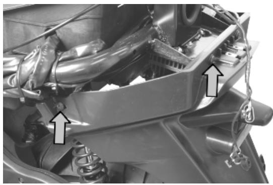
See also
Side fairings
Air filter
- Undo the two screws indicated.
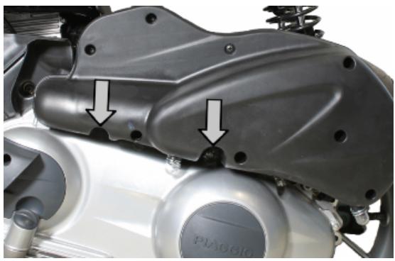
- Loosen the tightening screw of the carburettor sleeve to the filter.
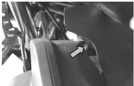
Rear mudguard
- From the right side of the vehicle, undo the screw indicated.
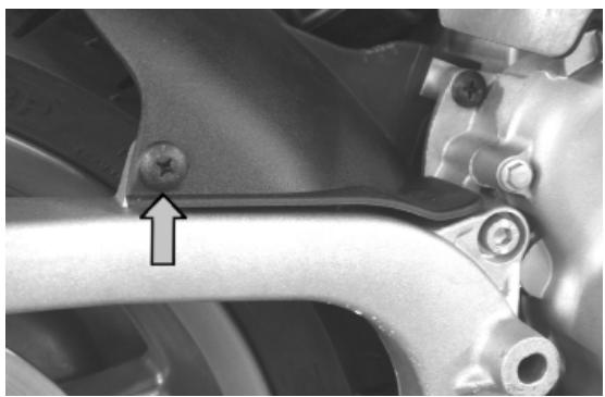
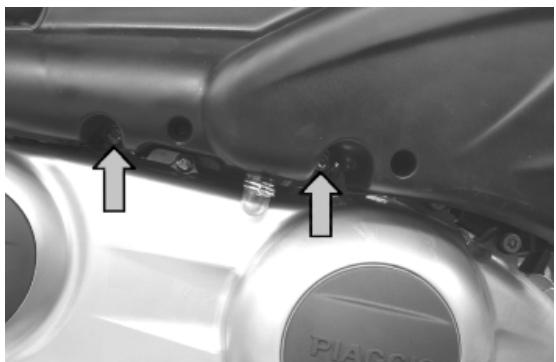
Helmet bay
- Remove the central frame cover.
- Remove the side fairings.
- Undo the three screws indicated on both sides of the vehicle.
- Release the wiring from the helmet compartment.
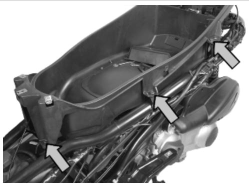
See also
Side fairings
Frame central cover
Fuel tank
- Remove the footrests.
- Disconnect the fuel delivery pipe.
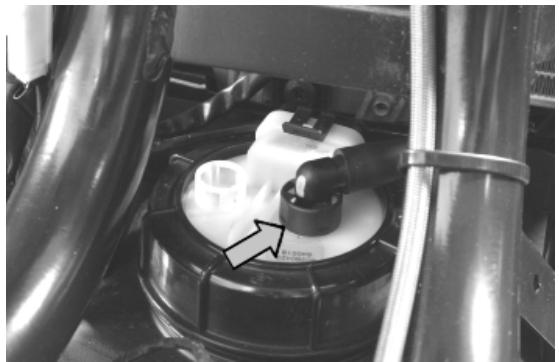
- Disconnect the power connector from the fuel pump.
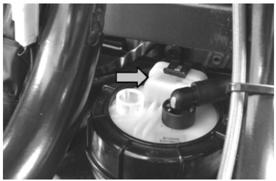
- Disconnect the connector of the probe checking fuel level.
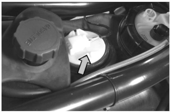
- Undo the screw indicated.
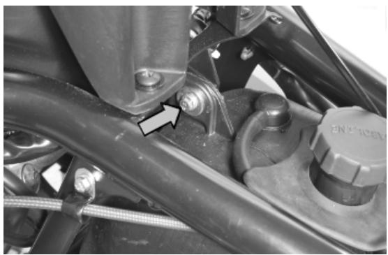
- Undo the screw indicated, placed under the vehicle at the back of the tank.
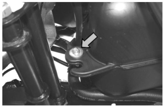
- Undo the screw indicated, placed under the vehicle at the front of the tank.
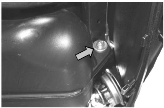
See also
Footrest
Front mudguard
- Undo the three screws indicated inside the mudguard.
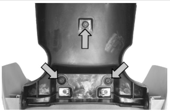
Radiator fan
- Remove the wheel housing.
- Disconnect the connector of the electric fan.
- Get a container of suitable capacity and disconnect the feeding and return cooling circuit pipes.
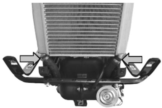
- Disconnect the feeding and return pipes from the expansion tank.
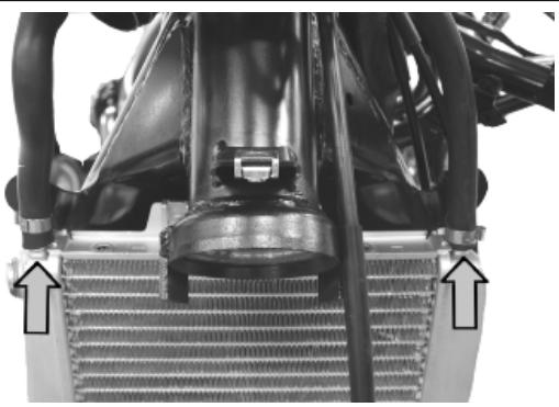
- Undo the fixing screw to the frame.
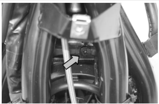
- Disconnect the radiator together with the electric fan from the chassis retainers.
- Once the radiator is removed, undo the three fixing screws to remove the electric fan.
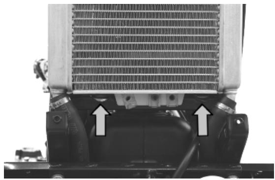
Expansion tank
- Remove the shield back plate.
- Disconnect the circuit de-aeration pipe.
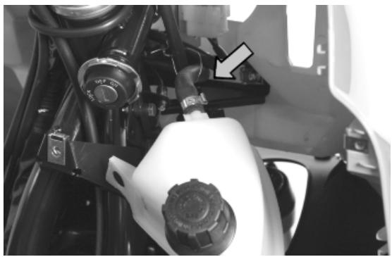
- Disconnect the circuit refill pipe.
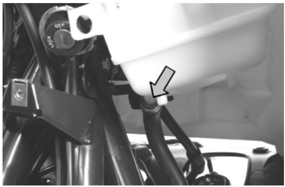
See also
Knee-guard
Front central cover
- Undo the screw indicated from both sides of the vehicle.
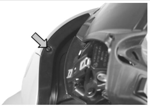
- Remove the PIAGGIO clip-on badge and undo the screw indicated.
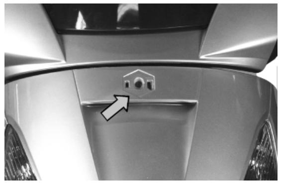
Flyscreen
- Remove both rear-view mirrors.
- Undo both rear-view mirrors supports.
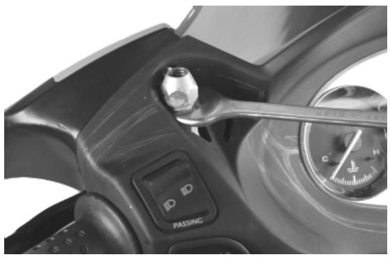
- Undo the screws indicated on both sides of the handlebar and remove the front frame.
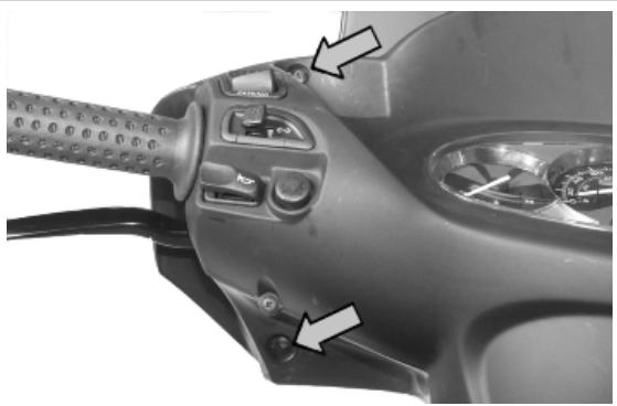
- Undo the four screws indicated and remove the windshield.
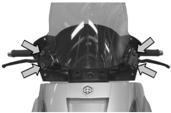
See also
Driving mirrors
Battery
- Lift the saddle
- Undo the two screws and remove the battery cover.
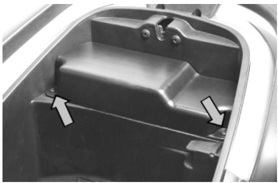
- Unscrew the two terminals and remove the battery.
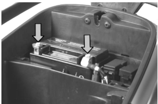
INDEX OF TOPICS
PRE-DELIVERY
PRE DE
Carry out the listed tests before delivering the vehicle.
Warning- be very careful when handling fuel.
Aesthetic inspection
Appearance checks:
- Paintwork
- Fitting of plastics
-Scratches
-Dirt
Tightening torques inspection
- Check visually that the following clamps are marked in yellow:
FRONT SUSPENSION
- Front wheel pin nut
- Screw fixing wheel pin on right fork leg
FRONT BRAKE
- Screws fixing front brake callipers to forks
- Brake pipes to front brake callipers couplings
REAR SUSPENSION
- Shock absorbers lower fixing screw
- Shock absorbers upper fixing screw
REAR BRAKE
- Screws fixing rear brake calliper to supporting plate
- Brake pipe to rear brake calliper coupling
SWINGING ARM
Swinging arm to engine pin locknut
STAND
Central stand bolt nuts
- Screw fixing muffler to muffler supporting arm
Electrical system
CAUTION
TO ENSURE MAXIMUM PERFORMANCE, THE BATTERY MUST BE CHARGED BEFORE USE. INADEQUATE CHARGING OF THE BATTERY WITH A LOW LEVEL OF ELECTROLYTE BEFORE IT IS FIRST USED SHORTENS THE LIFE OF THE BATTERY.
CAUTION
WHEN INSTALLING THE BATTERY, ATTACH THE POSITIVE LEAD FIRST AND THEN THE NEGATIVE LEAD.
-BATTERY ELECTROLYTE IS TOXIC AND IT MAY CAUSE SERIOUS BURNS. IT CONTAINS SULPHURIC ACID. AVOID CONTACT WITH EYES, SKIN AND CLOTHING.
IN CASE OF CONTACT WITH EYES OR SKIN, RINSE WITH ABUNDANT WATER FOR ABOUT 15 MINUTES AND SEEK MEDICAL ATTENTION AT ONCE.
IF IT IS SWALLOWED, IMMEDIATELY DRINK LARGE QUANTITIES OF WATER OR VEGETABLE OIL. SEEK IMMEDIATE MEDICAL ATTENTION.
THE BATTERIES PRODUCE EXPLOSIVE GAS; KEEP THEM AWAY FROM NAKED FLAMES, SPARKS AND CIGARETTES. VENTILATE THE AREA WHEN RECHARGING INDOORS.
ALWAYS WEAR EYE PROTECTION WHEN WORKING IN THE PROXIVITY OF BATTERIES.
KEEP OUT OF THE REACH OF CHILDREN
CAUTION
NEVER USE FUSES WITH A CAPACITY HIGHER THAN THE RECOMMENDED CAPACITY. USING A FUSE OF UNSUITABLE RATING MAY SERIOUSLY DAMAGE THE VEHICLE OR EVEN CAUSE A FIRE.
Levels check
Level check:
- Hydraulic brake system liquid level.
Rear hub oil level
- Engine coolant level
- Engine oil level
Road test
Test ride
Static test
Static control after the test ride:
Hot engine restart
- Minimum seal (turning the handlebar)
Uniform steering rotation
Possible losses
- electric radiator fan operation
CAUTION
CHECK AND ADJUST TYRE PRESSURE WITH TYRES AT AMBIENT TEMPERATURE.
CAUTION
NEVER EXCEED THE RECOMMENDED INFLATION PRESSURES OR TYRES MAY BURST.
Functional inspection
Functional check up:
- Hydraulic braking system: lever travel
- Clutch: proper functioning check
- Engine: proper general functioning and no abnormal noise check
- Other: papers check, frame and engine number check, tools and equipment, licence plate fitting, lock check, tyre pressure check, rear-view mirror and any accessory fitting
INDEX OF TOPICS
TIME
TIME
This section is devoted to the time necessary to carry out repairs.
For each operation, the description, code and time envisages are specified.
Engine
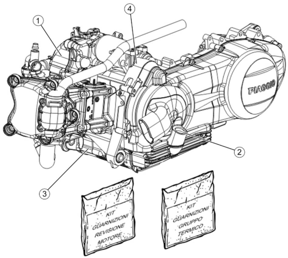
ENGINE
| Code | Action | Duration |
| 1 | 001001 | Engine from frame - Removal and refit. | |
| 2 | 003064 | Engine oil - change | |
| 3 | 001127 | Engine - Complete service | |
| 4 | 003057 | Engine retainer - Tighten nuts | |
Crankcase
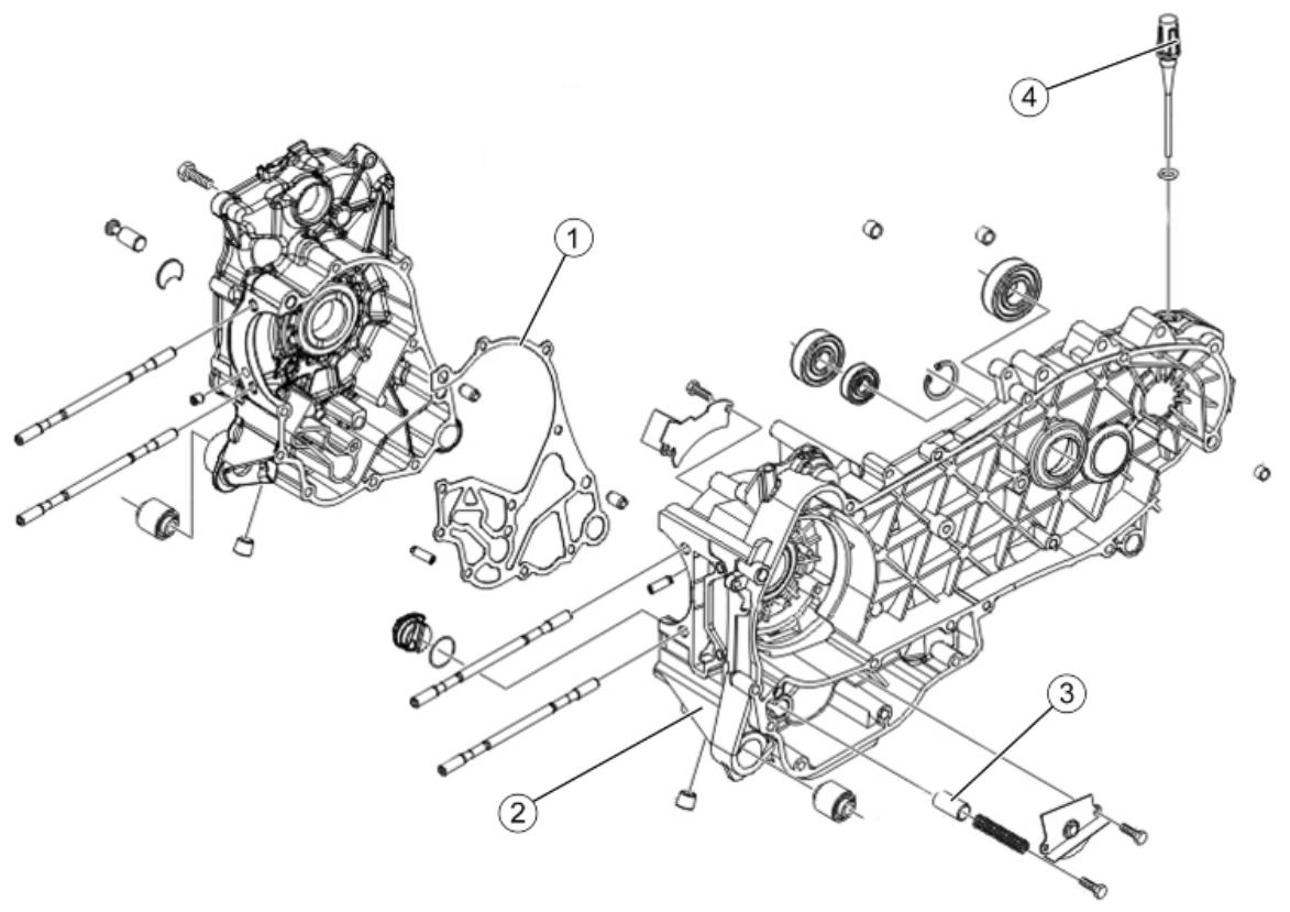
CRANKCASE
| Code | Action | Duration |
| 1 | 001153 | Crankcase halves gasket - Replacement | |
| 2 | 001133 | Engine crankcase- Replacement | |
| 3 | 001124 | Lubrication by-pass - Re- placement | |
| 4 | 002028 | Rear wheel hub - Replacement | |
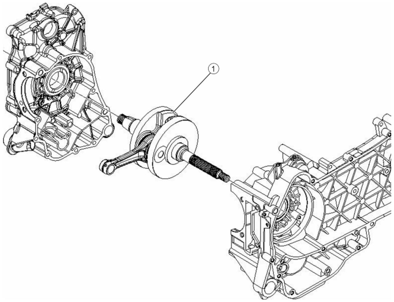
Crankshaft
CRANKSHAFT
| Code | Action | Duration |
| 1 | 001117 | Crankshaft - Replacement | |
Cylinder assay.
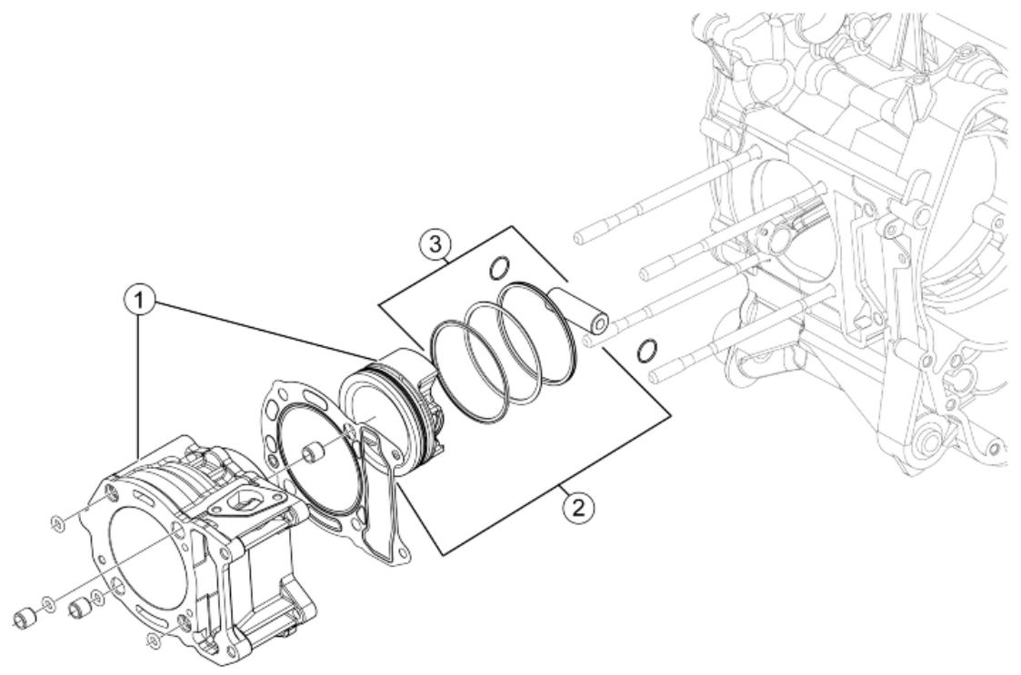
CYLINDER- PISTON
| Code | Action | Duration |
| 1 | 001002 | Cylinder-Piston - Replacement | |
| 2 | 001154 | Pin ring piston unit - Service | |
| 3 | 001176 | Rings / Pin - Replacement | |
Cylinder head assay.
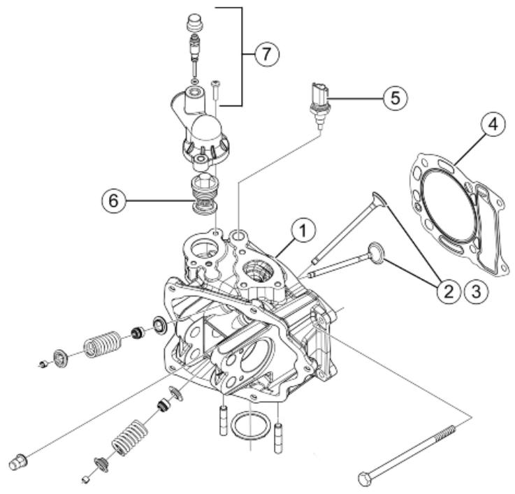
VALVE HEAD
| Code | Action | Duration |
| 1 | 001126 | Head - Replacement | |
| 2 | 001045 | Valves - Replacement | |
| 3 | 001049 | Valves - Adjustment | |
| 4 | 001056 | Head gasket - Replacement | |
| 5 | 000235 | Coolant temperature sensor -Replac. | |
| 6 | 001057 | Thermostat - Replacement | |
| 7 | 007012 | Coolant bleed valve - Re-placement | |
Rocker arms support assy.
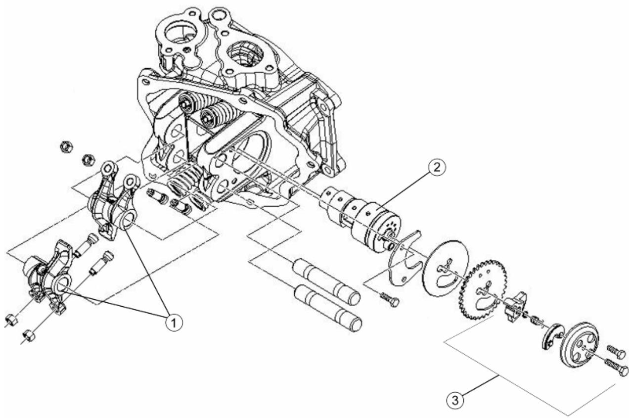
CAM SHAFT
| Code | Action | Duration |
| 1 | 001148 | Rocking lever valve - Re-placement | |
| 2 | 001044 | Camshaft - Replacement | |
| 3 | 001169 | Decompressor - Replacement | |
Cylinder head cover
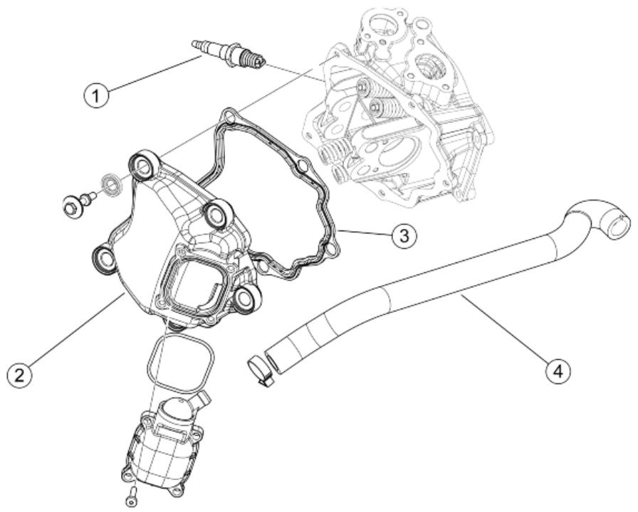
HEAD COVER
| Code | Action | Duration |
| 1 | 001093 | Spark plug - Replacement | |
| 2 | 001089 | Head cover - Replacement | |
| 3 | 001088 | Head cover gasket - Replacement | |
| 4 | 001074 | Oil vapour recovery pipe - Replacement | |
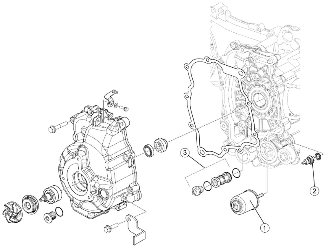
Oil filter
OIL FILTER
| Code | Action | Duration |
| 1 | 001123 | Oil filter -Replacement | |
| 2 | 001160 | Oil pressure sensor - Re-placement | |
| 3 | 001102 | Net oil filter - Replacement / Cleaning | |
Flywheel cover
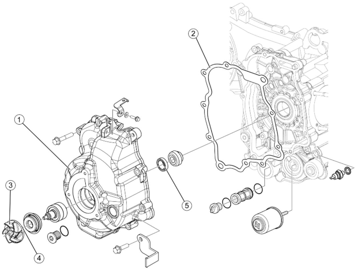
FLYWHEEL COVER
| Code | Action | Duration |
| 1 | 001087 | Flywheel cover - replace | |
| 2 | 001150 | Flywheel cover gasket - Replacement | |
| 3 | 007007 | Water pump rotor cover | |
| 4 | 001113 | Water pump / Pump rotor - Replacement | |
| 5 | 001099 | Oil seal, flywheel side - Replacement | |
Driven pulley
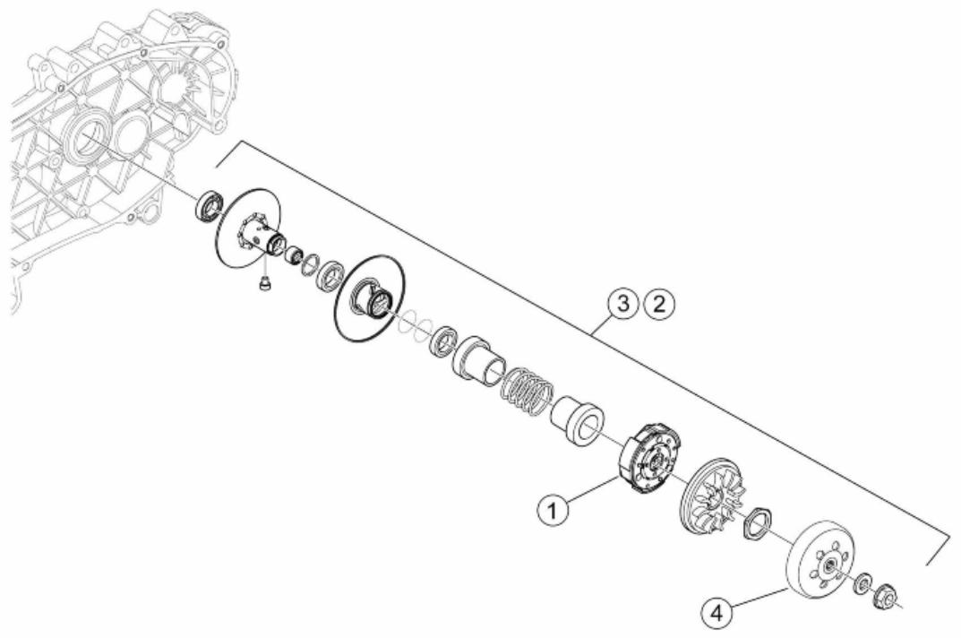
DRIVEN PULLEY
| Code | Action | Duration |
| 1 | 001022 | Clutch - Replacement | |
| 2 | 001012 | Driven pulley - Service | |
| 3 | 001110 | Driven pulley - Replacement | |
| 4 | 001155 | Clutch bell - Replacement | |
Oil pump
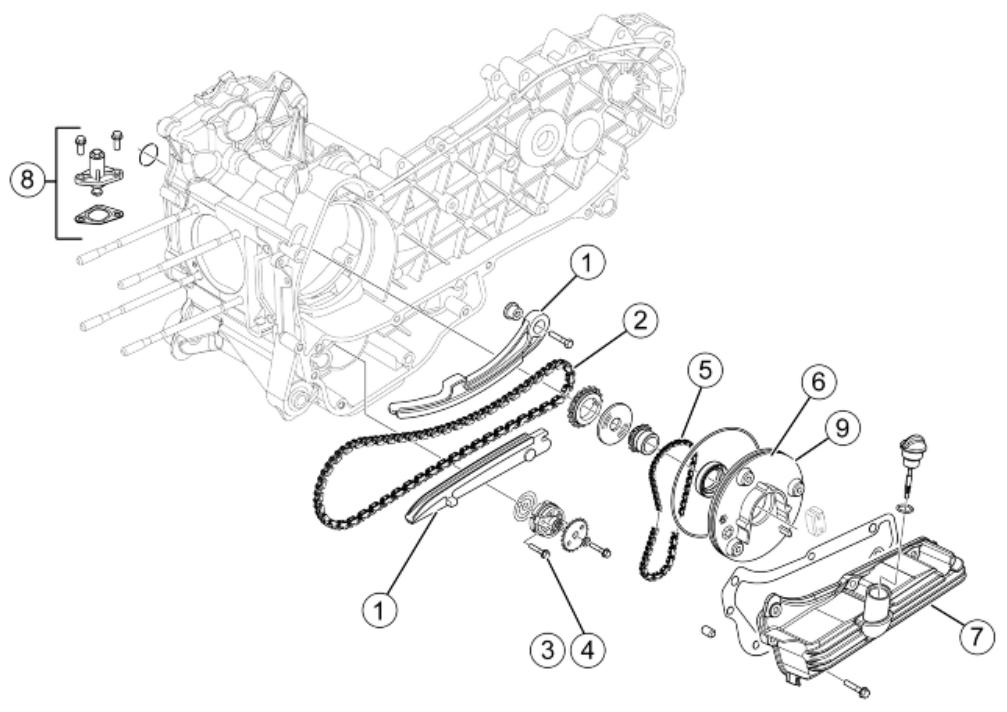
OIL PUMP
| Code | Action | Duration |
| 1 | 001125 | Chain guide pads - change | |
| 2 | 001051 | Belt - Distribution chain - Re-placement | |
| 3 | 001042 | Oil pump - overhaul | |
| 4 | 001112 | Oil pump - change | |
| 5 | 001122 | Oil pump chain - Replacement | |
| 6 | 001172 | Chain cover flap - change | |
| 7 | 001130 | Oil sump - change | |
| 8 | 001129 | Chain tightener - Overhaul and replacement | |
| 9 | 888133 | Chain cover flap - Check / replacement | |
Final gear assay.
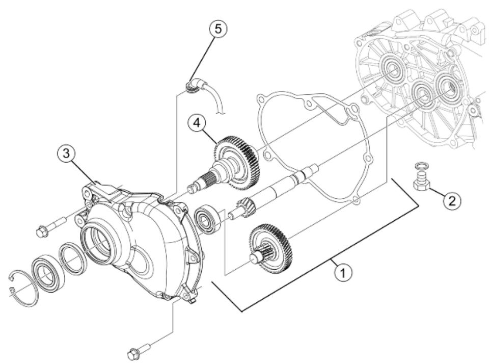
FINAL REDUCTION
| Code | Action | Duration |
| 1 | 001010 | Reduction gear - Replacement | |
| 2 | 003065 | Gear box oil - Replacement | |
| 3 | 001156 | Geared reduction unit cover - Replacement | |
| 4 | 004125 | Rear wheel axle - Replacement | |
| 5 | 004180 | Reduction gear pipe - Re- placement | |
Driving pulley
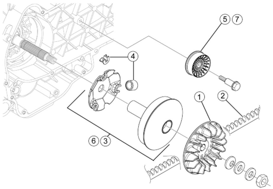
DRIVING PULLEY
| Code | Action | Duration |
| 1 | 001086 | Driving half-pulley - Replacement | |
| 2 | 001011 | Driving belt - Replacement | |
| 3 | 001066 | Driving pulley - Removal and Refitting | |
| 4 | 001177 | Variator rollers / shoes - Replacement | |
| 5 | 001141 | Belt anti-flapping roller - Replacement | |
| 6 | 001006 | driving pulley - Service | |
| 7 | 001175 | Anti-flapping roller/ Belt - Service | |
Transmission cover
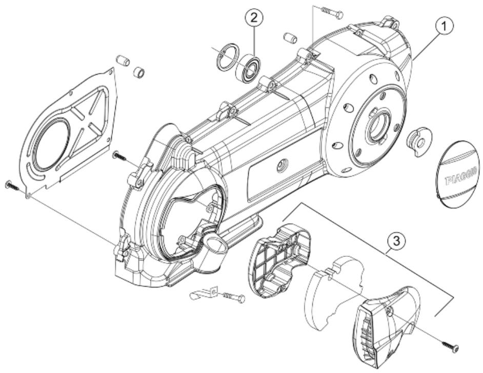
TRANSMISSION COVER
| Code | Action | Duration |
| 1 | 001096 | Transmission crankcase cover - Replacement | |
| 2 | 001135 | Transmission cover bearing - Replacement | |
| 3 | 001170 | Air duct - Replacement | |
Water pump
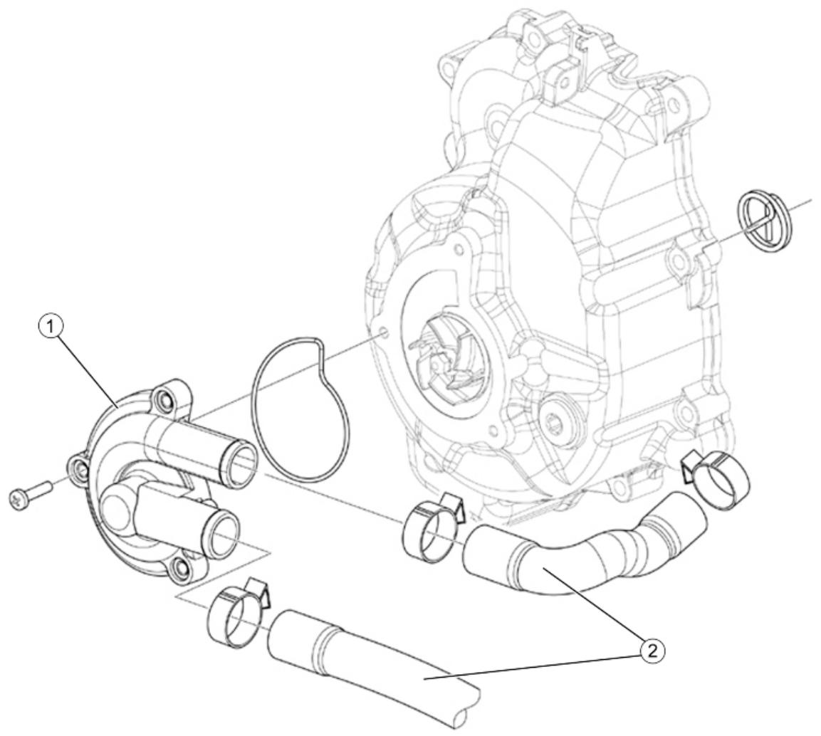
WATER PUMP
| Code | Action | Duration |
| 1 | 007017 | Water pump cover - Replacement | |
| 2 | 007003 | Coolant delivery and return pipe - Replacement | |
Starter motor
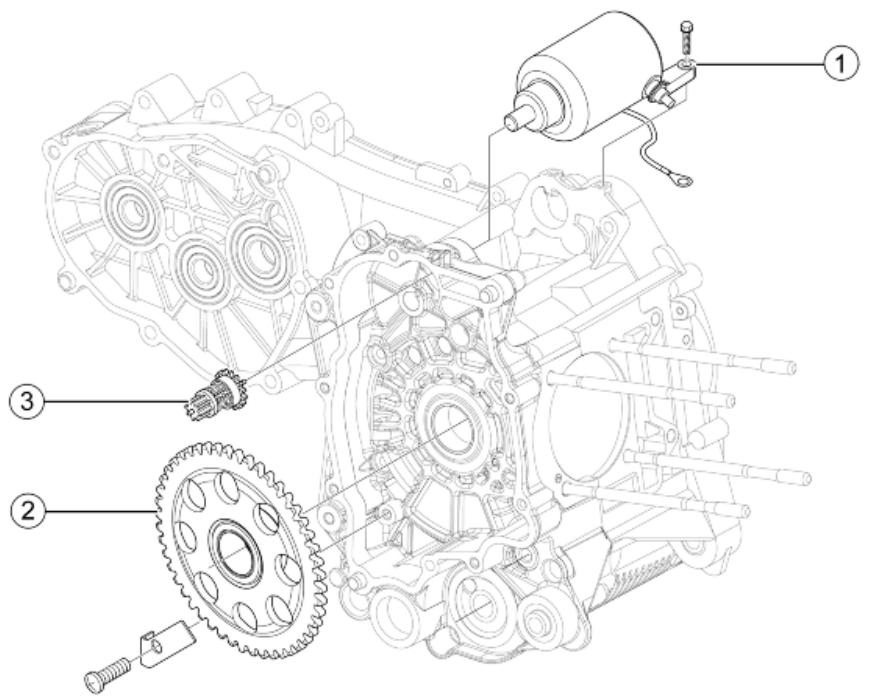
ELECTRICAL START-UP
| Code | Action | Duration |
| 1 | 001020 | Starter motor - Replacement | |
| 2 | 001151 | Start-up driven gearing - Re-placement | |
| 3 | 001017 | Start-up pinion - Replace-ment | |
Flywheel magneto
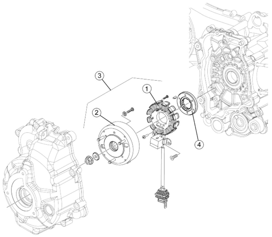
MAGNETO FLYWHEEL
| Code | Action | Duration |
| 1 | 001067 | Stator - Removal and Refit- ting | |
| 2 | 001173 | Rotor - Replacement | |
| 3 | 001058 | Complete flywheel - Replace- ment | |
| 4 | 001104 | Start-up freewheel - Replace- ment | |
Butterfly valve
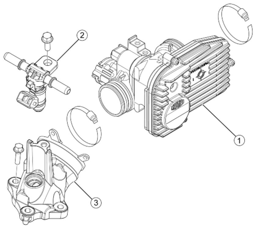
THROTTLE BODY
| Code | Action | Duration |
| 1 | 001166 | Throttle body - Replacement | |
| 2 | 001047 | Injector - Replacement | |
| 3 | 001013 | Intake manifold - change | |
Exhaust pipe
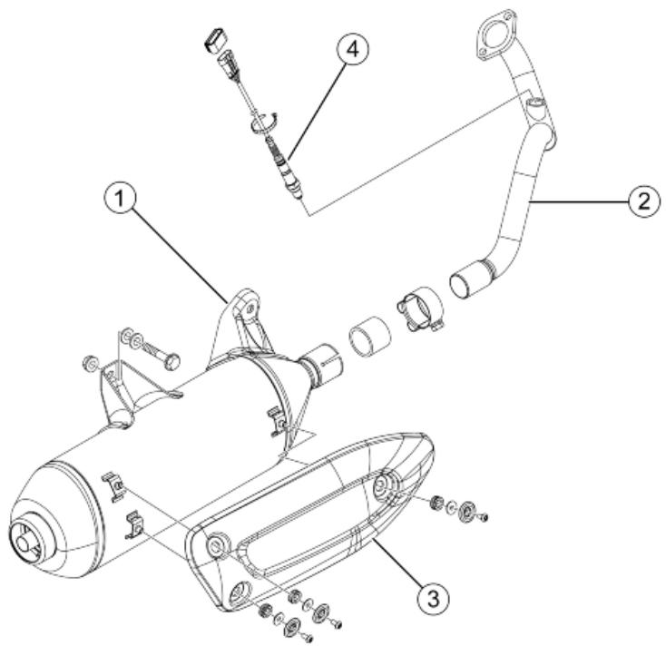
MUFFLER
| Code | Action | Duration |
| 1 | 001009 | Muffler - Replacement | |
| 2 | 001092 | Exhaust manifold - Replacement | |
| 3 | 001095 | Muffler guard - Replacement | |
| 4 | 005138 | Lambda probe - Replacement | |
Air cleaner
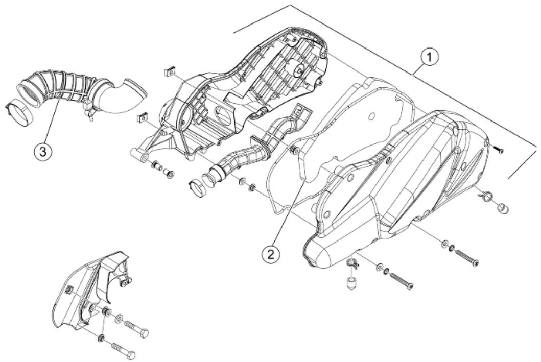
AIR CLEANER
| Code | Action | Duration |
| 1 | 001015 | Air filter box - Replacement | |
| 2 | 001014 | Air filter - Replacement / cleaning | |
| 3 | 004122 | Air cleaner/ carburettor fitting
- Replacement | |
Frame
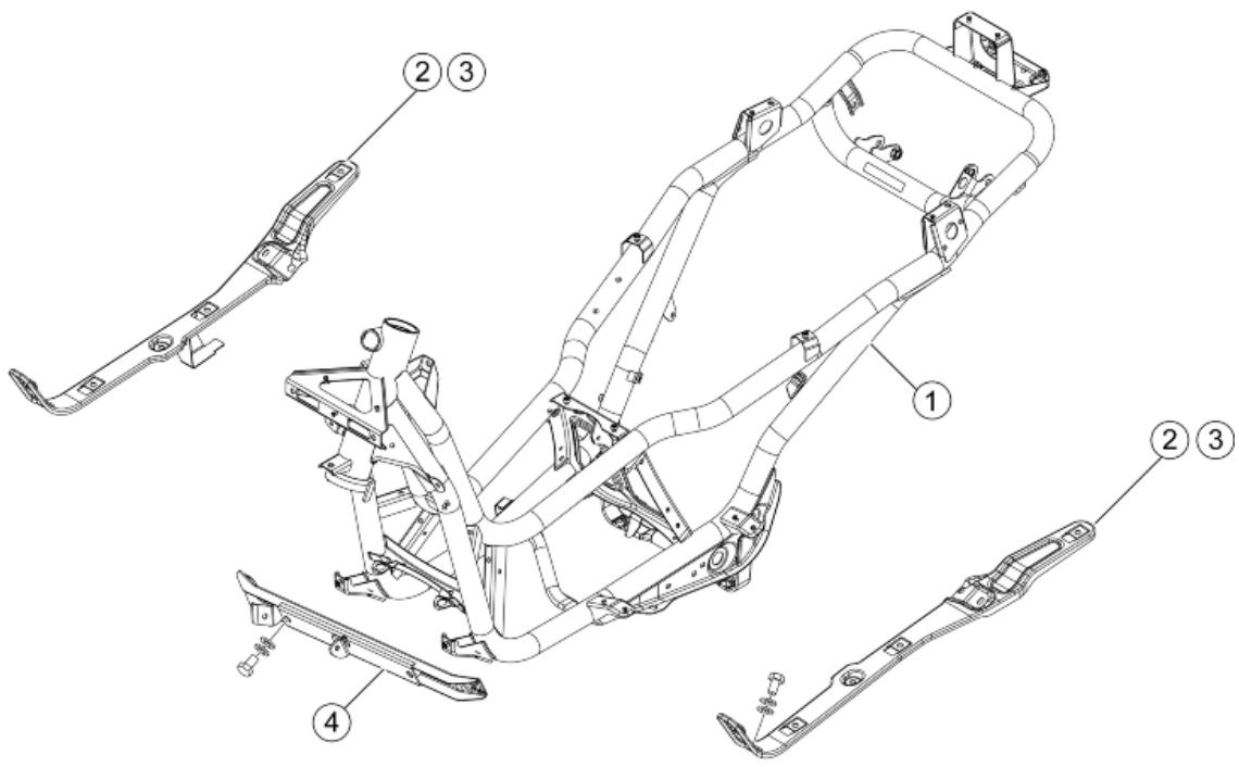
CHASSIS
| Code | Action | Duration |
| 1 | 004001 | Chassis - Replacement | |
| 2 | 004147 | Footrest support bracket, one side - Replacement | |
| 3 | 004148 | footrest support bracket, both sides - Replacement | |
| 4 | 004146 | Front frame - Replacement | |
Centre-stand
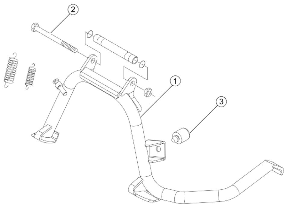
STAND
| Code | Action | Duration |
| 1 | 004004 | Stand - Replacement | |
| 2 | 001053 | Stand bolt - Replacement | |
| 3 | 004179 | Stand buffer - Replacement | |
Legshield spoiler
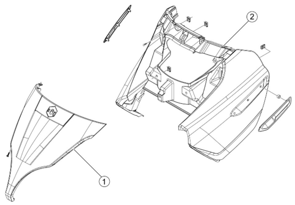
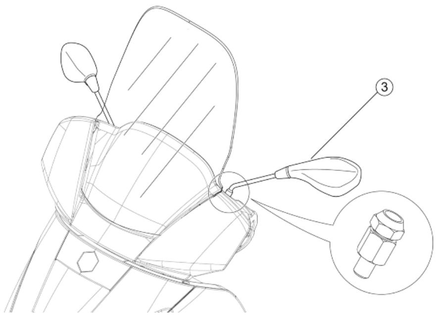
FRONT SHIELD
| Code | Action | Duration |
| 1 | 004020 | Headlight frame - Replacement | |
| 2 | 004064 | Front shield, front section - Replacement | |
| 3 | 004066 | Driving mirror - Replacement | |
Side fairings
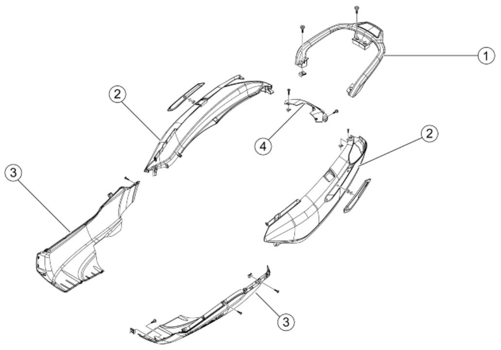
SIDE COVERS
| Code | Action | Duration |
| 1 | 004068 | Passenger handgrip - Re-placement | |
| 2 | 004085 | Fairing (1) - Replacement | |
| 3 | 004053 | Spoiler - Replacement | |
| 4 | 004036 | Frame cover - Replacement | |
Rear cover
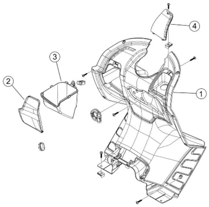
SHIELD BACK PLATE
| Code | Action | Duration |
| 1 | 004065 | Shield back plate - Replacement | |
| 2 | 004156 | Glove box flap and/or support - Replacement | |
| 3 | 004145 | Glove box - Replacement | |
| 4 | 007024 | Expansion tank cap - Replacement | |
Central cover
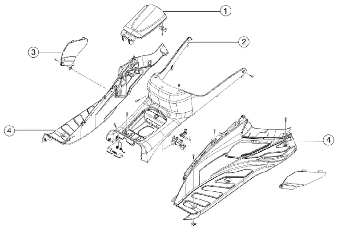
CENTRAL COVER
| Code | Action | Duration |
| 1 | 004135 | Fuel tank port - Replacement | |
| 2 | 004011 | Central chassis cover - Re-placement | |
| 3 | 004059 | Spark plug inspection flap - Replacement | |
| 4 | 004015 | Footrest - Replacement | |
Mudguard
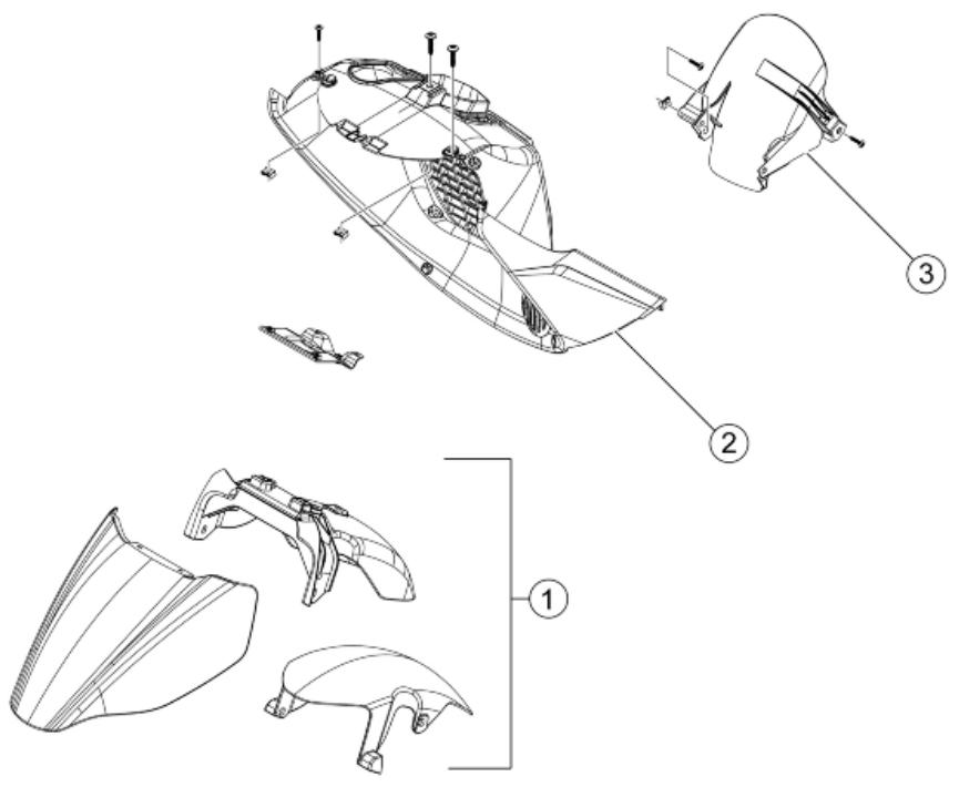
MUDGUARDS
| Code | Action | Duration |
| 1 | 004002 | Front mudguard - Replacement | |
| 2 | 004167 | Grill / radiator cover - Replacement | |
| 3 | 004009 | Rear mudguard - Replacement | |
Fuel tank
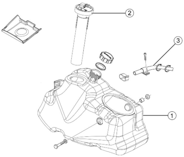
FUEL TANK
| Code | Action | Duration |
| 1 | 004005 | Fuel tank - Replacement | |
| 2 | 005010 | Tank float - Replacement | |
| 3 | 004109 | Fuel tank breather - Replacement | |
Rear shock-absorber
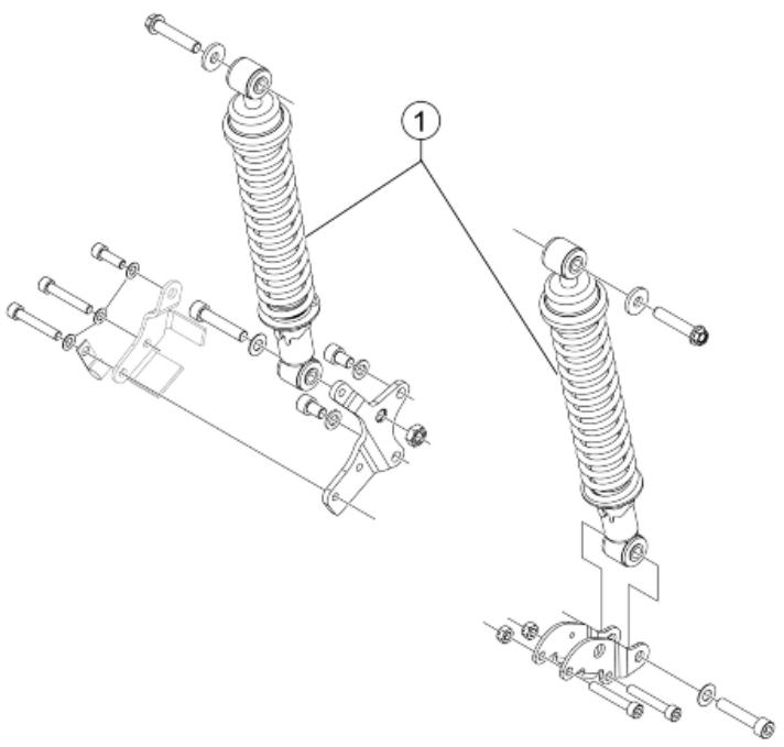
REAR SHOCK ABSORBER
| Code | Action | Duration |
| 1 | 003007 | Rear shock absorber - Re-placement | |
Handlebar covers
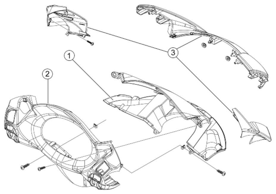
HANDLEBAR COVERS
| Code | Action | Duration |
| 1 | 004018 | Front handlebar covers - Replacement | |
| 2 | 004019 | Rear handlebar covers - Replacement | |
| 3 | 004101 | Windshield - Replacement | |
Handlebar components
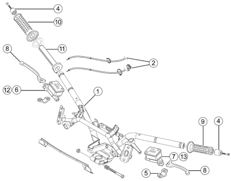
HANDLEBARCOMPONENTS
| Code | Action | Duration |
| 1 | 003001 | Handlebar - Replacement | |
| 2 | 002063 | Complete throttle control - Replacement | |
| 3 | 003061 | Accelerator transmission - Adjustment | |
| 4 | 003059 | Counterweight - Replacement | |
| 5 | 004162 | Mirror support and/or brake pump fitting U-bolt - Replacement | |
| 6 | 002024 | Front brake pump - Replacement | |
| 7 | 002067 | Rear brake pump - Replacement | |
| 8 | 002037 | Brake lever - Replacement | |
| 9 | 002071 | Left knob - Replacement | |
| 10 | 002059 | Right-hand knob - change | |
| 11 | 002060 | Complete throttle control - Replacement | |
| 12 | 002047 | Front brake fluid and air bleeding system - Replacement | |
| 13 | 002080 | Rear brake oil bleeding system - Replacement | |
Swing-arm
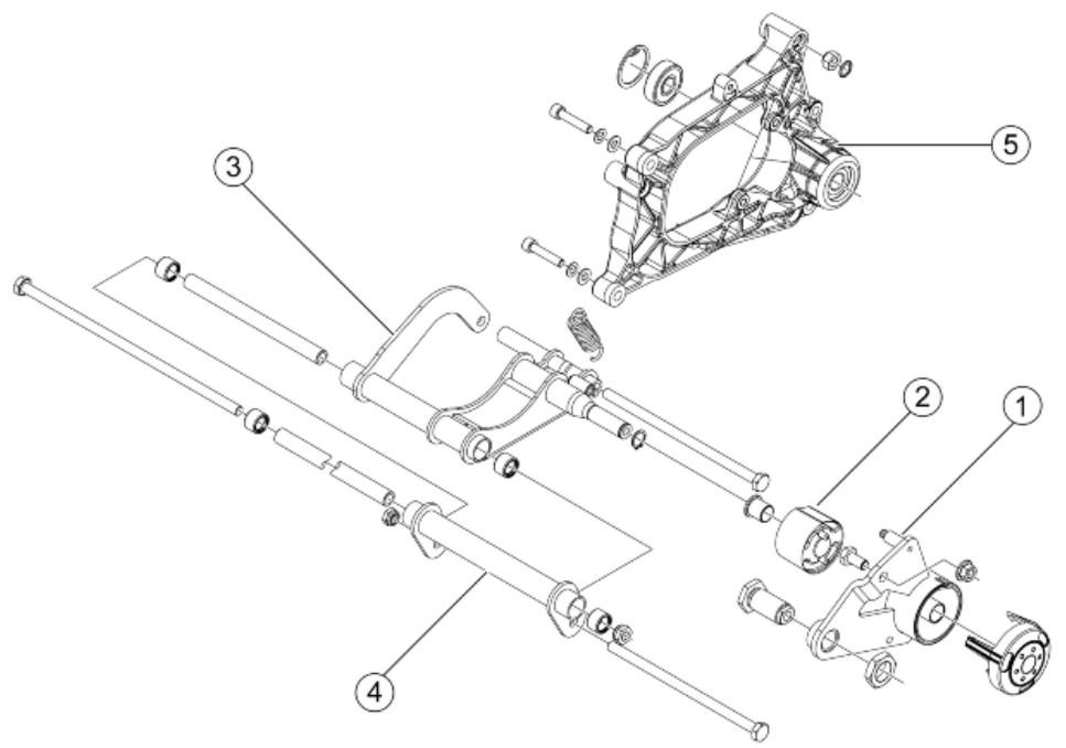
SWINGING ARM
| Code | Action | Duration |
| 1 | 003081 | Swinging arm support flange - replace | |
| 2 | 004058 | Silent-block - replace | |
| 3 | 001072 | Engine /frame swinging arm attachment - replace | |
| 4 | 003080 | Swinging arm on frame - Replacement | |
| 5 | 003077 | Muffler supporting arm/ rear shock absorber - Replacement | |
Seat
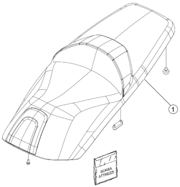
SADDLE
| Code | Action | Duration |
| 1 | 004003 | Saddle - Replacement | |
Instrument panel
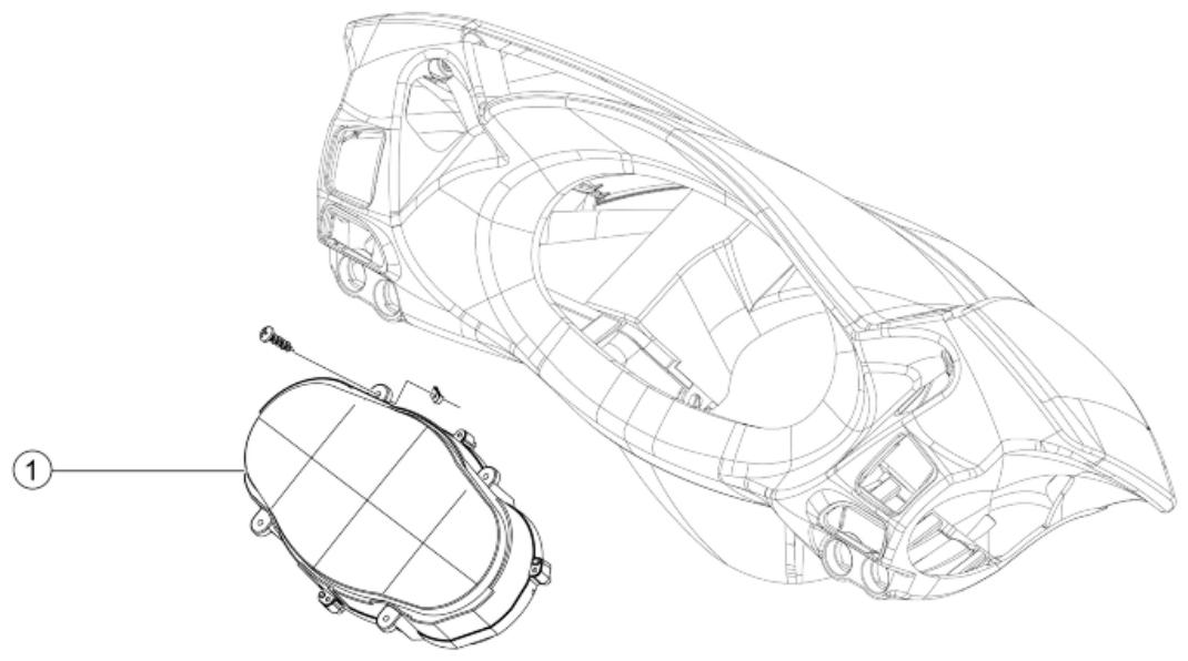
INSTRUMENT PANEL
| Code | Action | Duration |
| 1 | 005014 | Odometer - Replacement | |
Locks
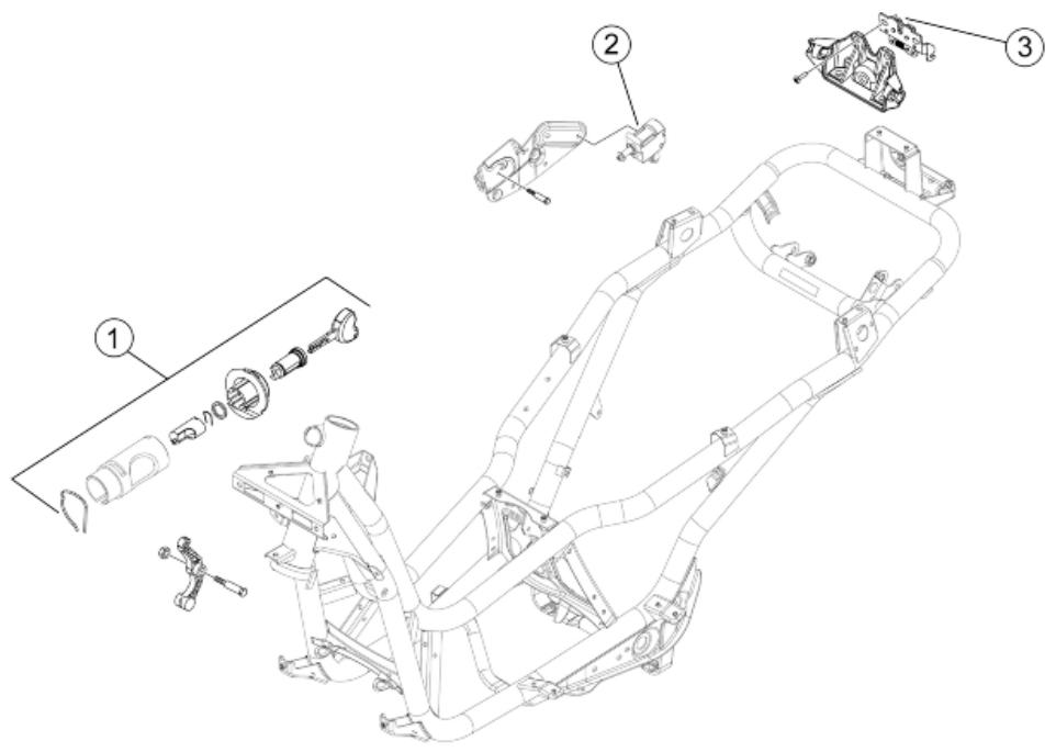
LOCKS
| Code | Action | Duration |
| 1 | 004010 | Anti-theft lock - Replacement | |
| 2 | 005099 | Electric saddle opening device - Replacement | |
| 3 | 004054 | Saddle lock catch - Replacement | |
Turn signal lights
Rear lights
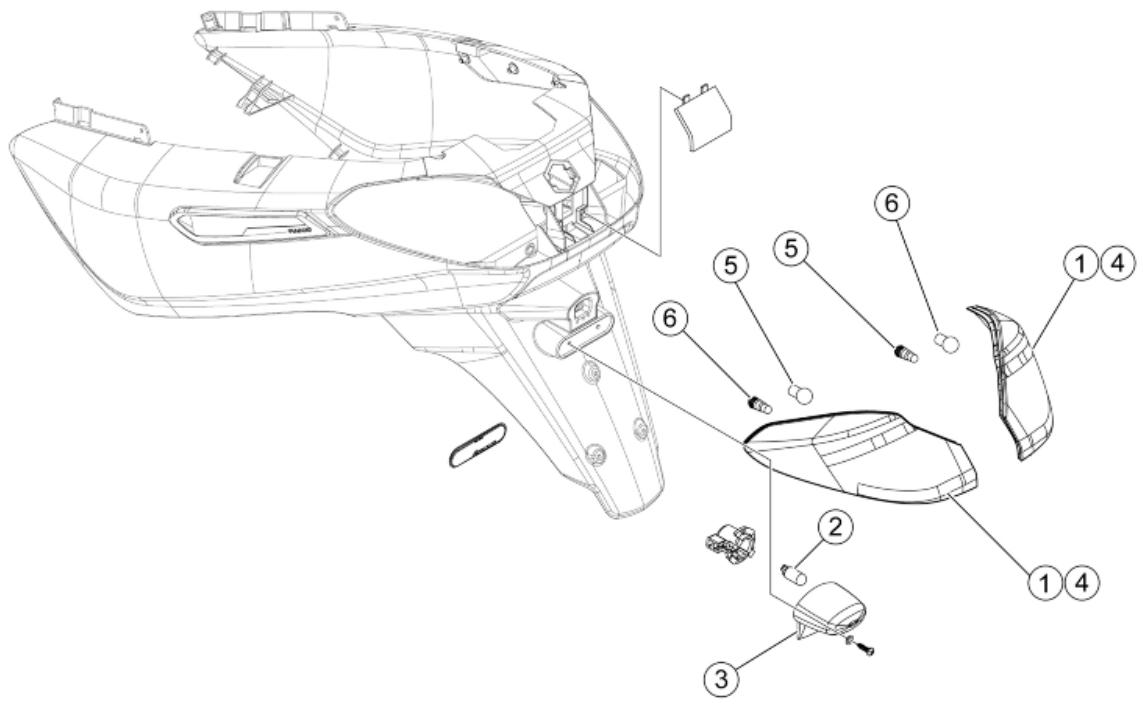
REAR LIGHTS
| Code | Action | Duration |
| 1 | 005005 | Taillight - Replacement | |
| 2 | 005031 | Licence plate light bulb - Re- placement | |
| 3 | 005032 | Transparent licence plate cover - replace | |
| 4 | 005022 | Rear turn indicators - Re- placement | |
| 5 | 005066 | Rear light bulbs - Replacement | |
| 6 | 005068 | Rear turn indicator bulb - Re- placement | |
Front lights
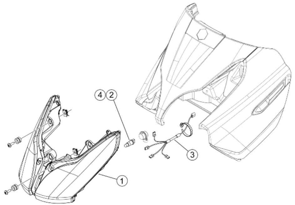
TURN INDICATOR LIGHTS
| Code | Action | Duration |
| 1 | 005002 | Front light - Replacement | |
| 2 | 005008 | Light bulbs - Replacement | |
| 3 | 005044 | Front lights cable unit- Replacement | |
| 4 | 005067 | Front direction indicator bulb - Replacement | |
Front wheel
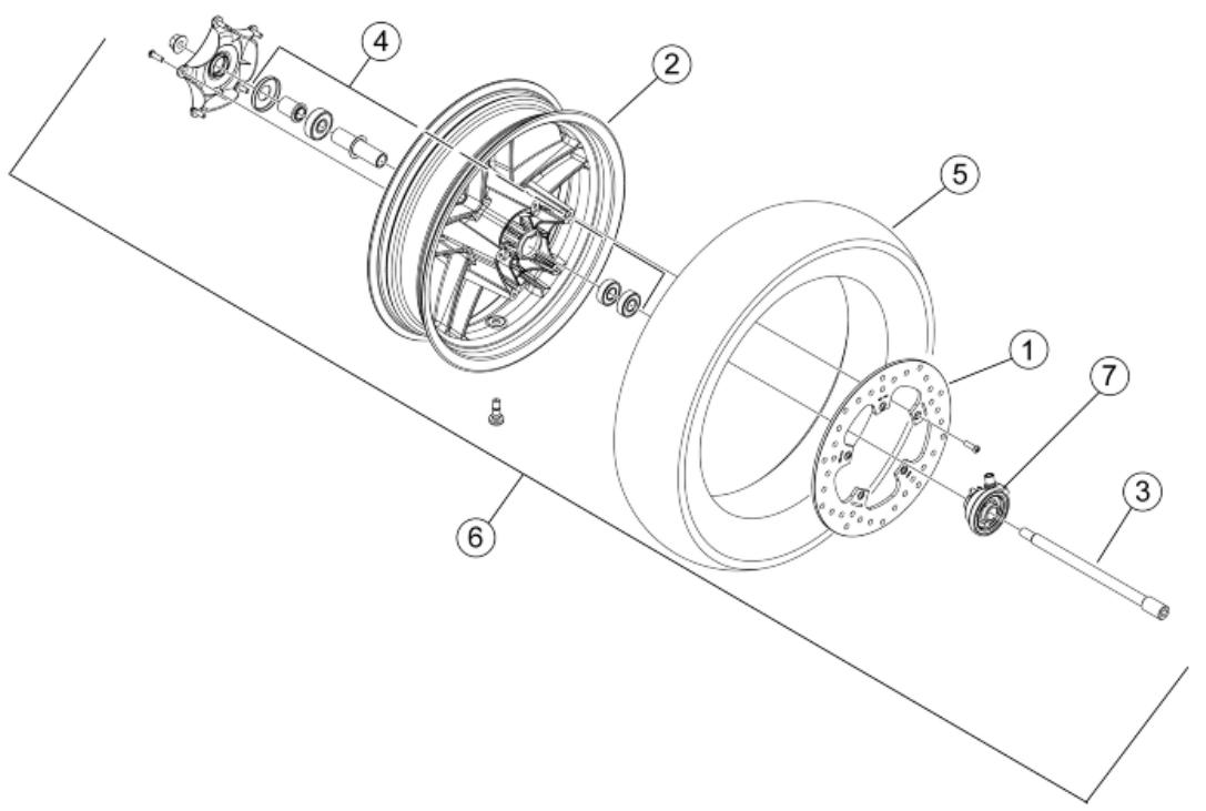
FRONT WHEEL
| Code | Action | Duration |
| 1 | 002041 | Front brake disc - Replacement | |
| 2 | 003037 | Front wheel rim- Replacement | |
| 3 | 003038 | Front wheel axle - Replacement | |
| 4 | 003040 | Front wheel bearings - Replacement | |
| 5 | 003047 | Front tyre - replace | |
| 6 | 004123 | Front wheel - Replacement | |
| 7 | 002011 | Odometer drive- Replacement | |
Rear wheel
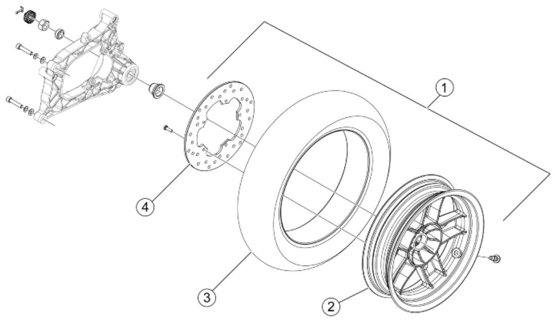
REAR WHEEL
| Code | Action | Duration |
| 1 | 001016 | Rear wheel - Replacement | |
| 2 | 001071 | Rear wheel rim - replace | |
| 3 | 004126 | Rear wheel tyre - Replacement | |
| 4 | 002070 | Rear brake disc - Replacement | |
Fuel pump
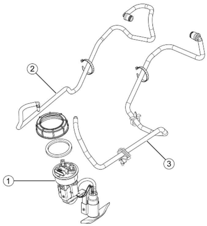
FUEL PUMP
| Code | Action | Duration |
| 1 | 004073 | Fuel pump - Replacement | |
| 2 | 004137 | Pump/ injector pipe - Re- placement | |
Electric devices
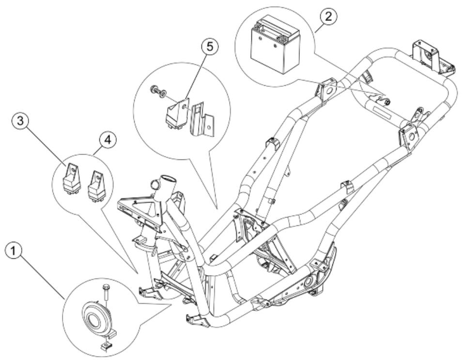
REMOTE CONTROLS
| Code | Action | Duration |
| 1 | 005003 | Horn - Replacement | |
| 2 | 005007 | Battery - Replacement | |
| 3 | 005075 | Stop remote control - Re-placement | |
| 4 | 005035 | Headlight remote control -Replacement | |
| 5 | 005011 | Start-up remote controlswitch - Replacement | |
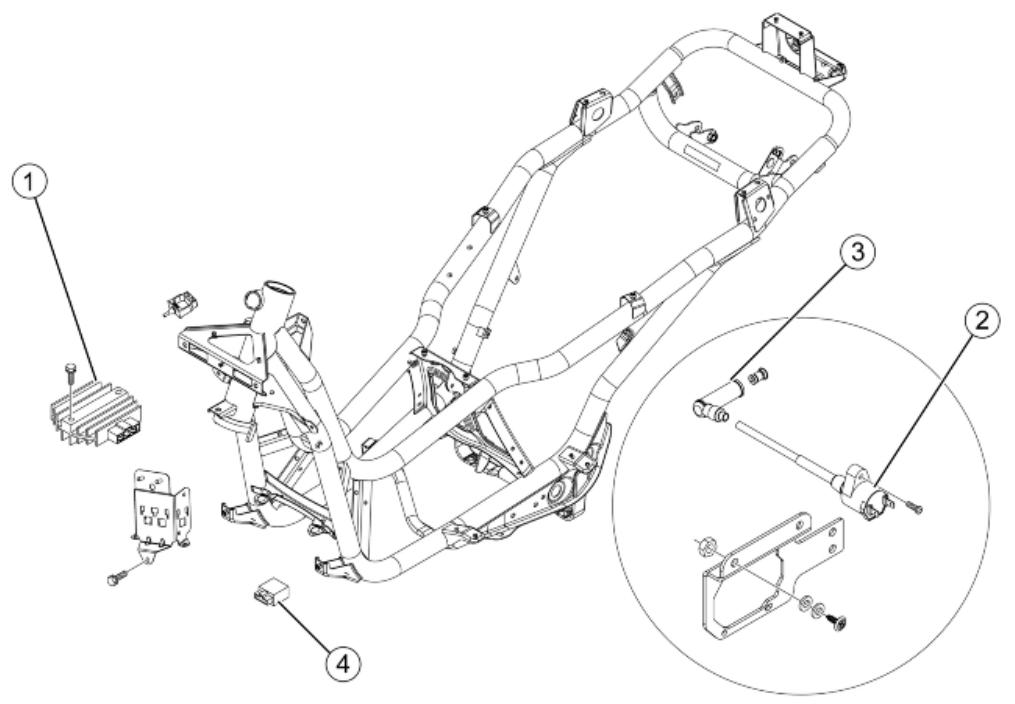
VOLTAGE REGULATOR
| Code | Action | Duration |
| 1 | 005009 | Voltage regulator - Replacement | |
| 2 | 001069 | HV coil - Replacement | |
| 3 | 001094 | Spark plug cap - Replacement | |
| 4 | 005119 | Fuel pump remote control - Replacement | |
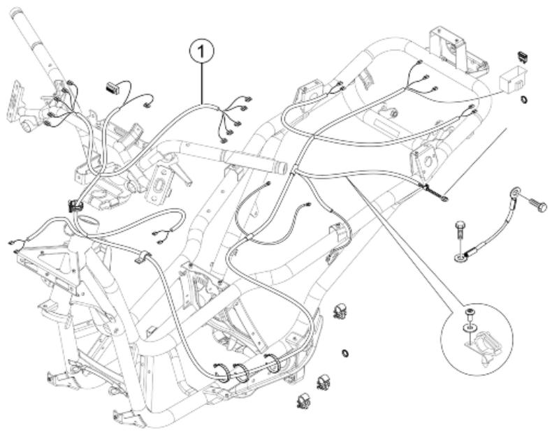
WIRE UNIT
| Code | Action | Duration |
| 1 | 005001 | Electrical system - Replacement | |
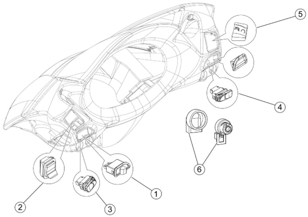
Electronic controls
ELECTRIC CONTROLS
| Code | Action | Duration |
| 1 | 005006 | Light switch or turn indicators - Replacement | |
| 2 | 005039 | Headlight switch - replace | |
| 3 | 005040 | Horn button - Replacement | |
| 4 | 005041 | Starter button - Replacement | |
| 5 | 005077 | Emergency stop switch - Re- placement | |
| 6 | 005016 | Key switch - Replacement | |
Transmissions
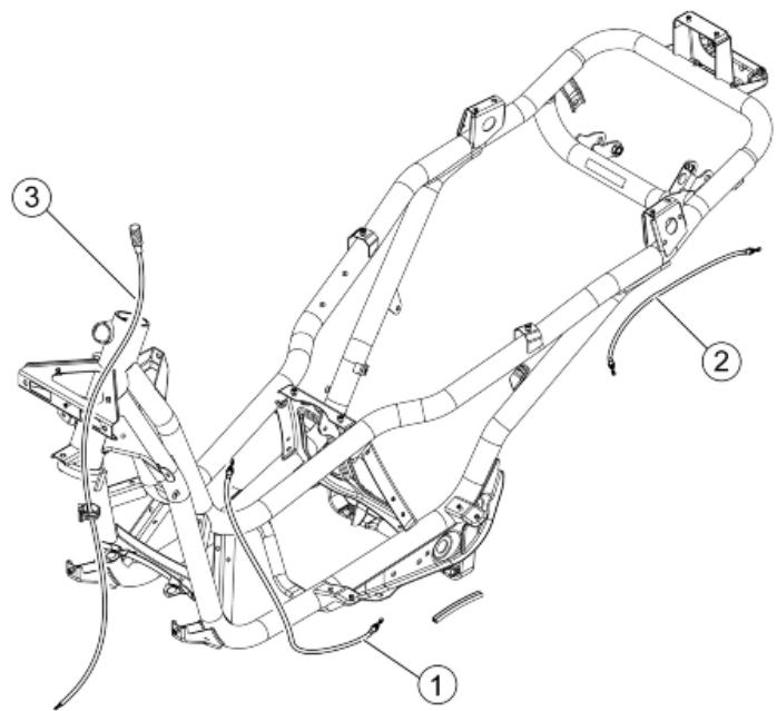
TRANSMISSIONS
| Code | Action | Duration |
| 1 | 002082 | Fuel tank cap opening drive - Replacement | |
| 2 | 002083 | Saddle opening transmission - Replacement | |
| 3 | 002049 | Odometer cable - Replacement | |
Helmet bay
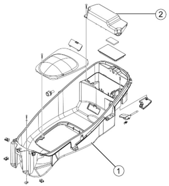
HELMET COMPARTMENT
| Code | Action | Duration |
| 1 | 004016 | Helmet compartment - Re-placement | |
| 2 | 005046 | Battery cover - change | |
Rear side fairings
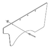
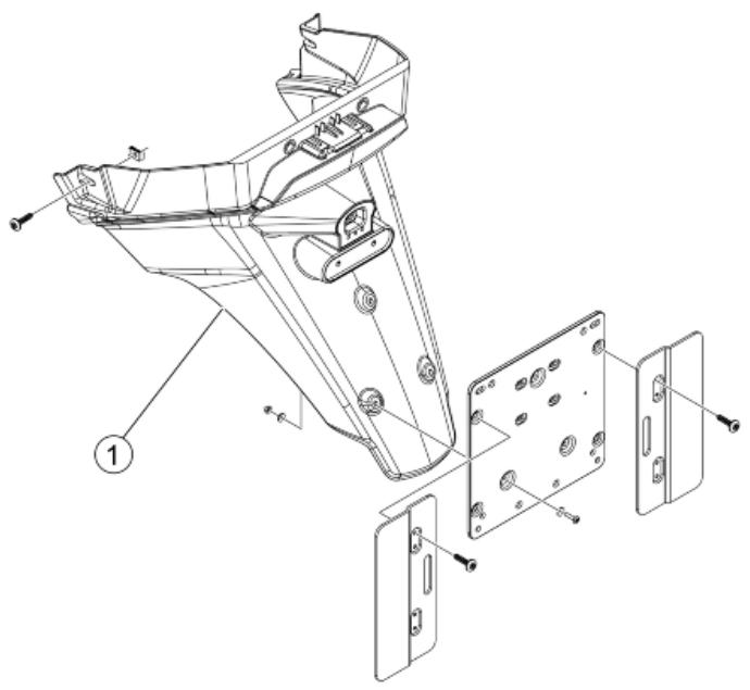
REAR COVERS
| Code | Action | Duration |
| 1 | 005048 | Licence plate holder - Re-placement | |
Front suspension
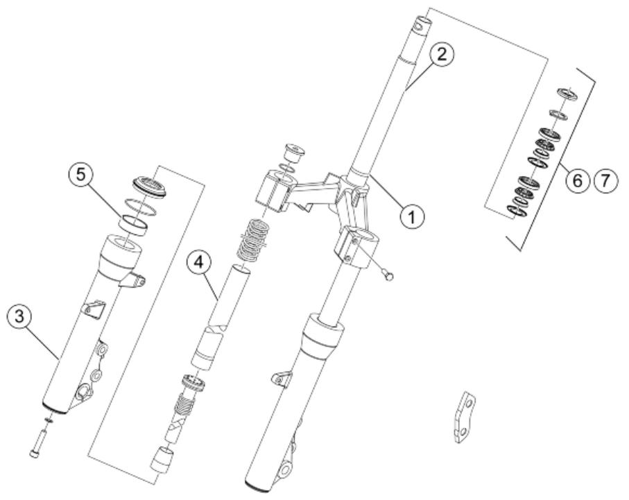
FRONT SUSPENSION
| Code | Action | Duration |
| 1 | 003051 | Complete fork - replace | |
| 2 | 003010 | Front suspension - Service | |
| 3 | 003076 | Fork sheath - Replacement | |
| 4 | 003079 | Fork stem - Replacement | |
| 5 | 003048 | Fork oil seal - Replacement | |
| 6 | 003002 | Steering thrust washer - Re-placement | |
| 7 | 003073 | Steering clearance - Adjust-ment | |
Cooling system
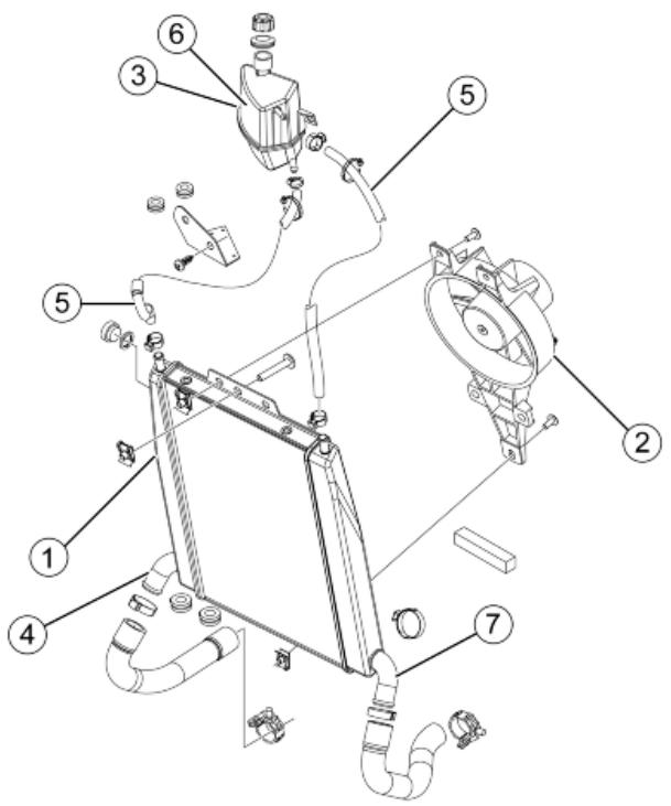
COOLING SYSTEM
| Code | Action | Duration |
| 1 | 007002 | Water radiator - replacement | |
| 2 | 007016 | Fan with support - Replacement | |
| 3 | 007001 | Expansion tank - Replacement | |
| 4 | 007022 | Coolant delivery pipe - Replacement | |
| 5 | 007013 | Radiator expansion tank con- nection pipe - Replacement | |
| 6 | 001052 | Coolant and air bleed - Re- placement | |
| 7 | 007019 | Connection water pump pipe / return pipe - Replace- ment | |
Braking system
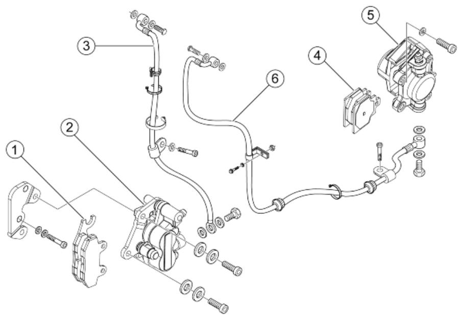
BRAKE SYSTEM
| Code | Action | Duration |
| 1 | 002007 | Front brake pads - Replacement | |
| 2 | 002039 | Front brake calliper - Replacement | |
| 3 | 002021 | Front brake piping - Replacement | |
| 4 | 002002 | Rear brake pads - Replacement | |
| 5 | 002048 | Rear brake calliper - Replacement | |
| 6 | 002020 | Rear brake disc piping - Replacement | |
Windscreen
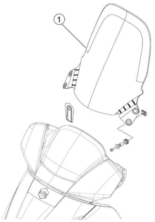
WINDSHIELD
| Code | Action | Duration |
| 1 | 004101 | Windshield - Replacement | |
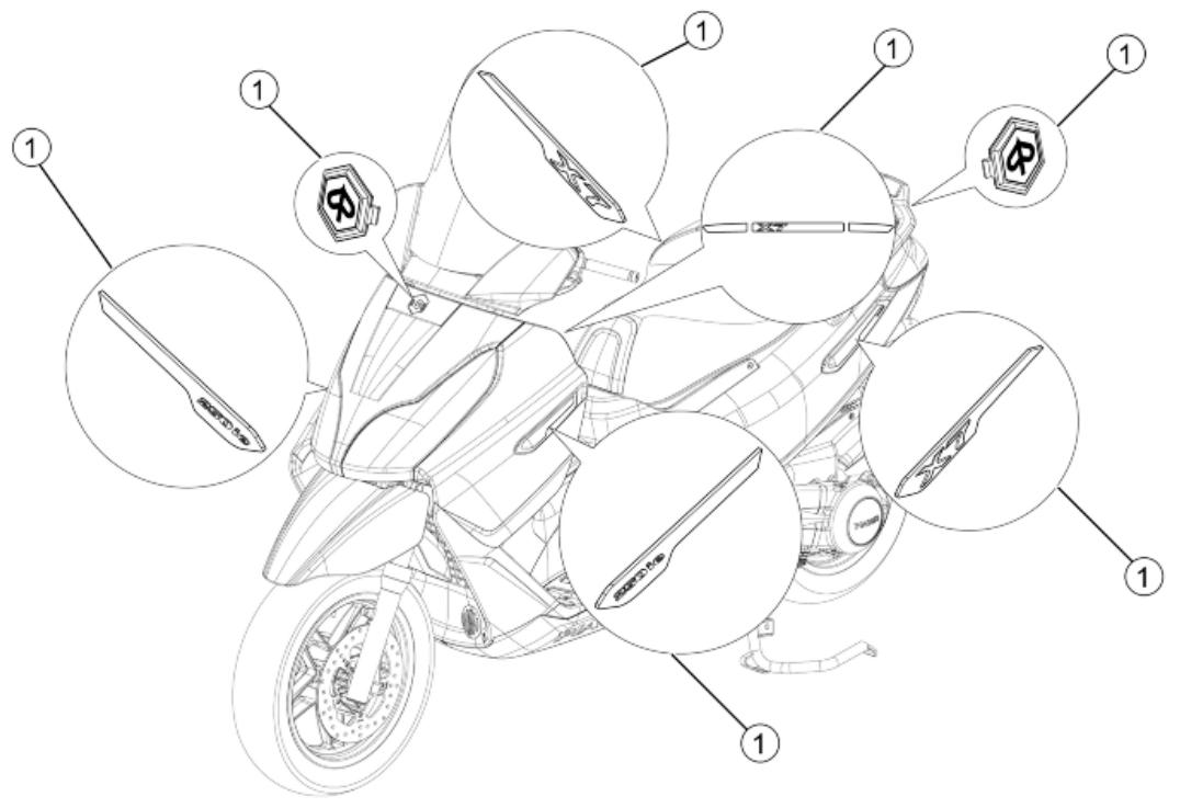
Stickers
TRANSFERS
| Code | Action | Duration |
| 1 | 004159 | Plates / Stickers - Replacement | |