MODE D'EMPLOI LIBERTY PIAGGIO
WORKSHOP MANUAL
633112

WORKSHOP MANUAL
Liberty 50 Catalyzed
The descriptions and illustrations supplied in this publication are not binding. PIAGGIO therefore reserves the right to make any changes to pieces, parts or accessory supplies, which it believes to be appropriate for improvement purposes or any requirement of a constructive or commercial nature, at any time, without the obligation to up-dating this publication before time, the essential characteristics of the type described and illustrated here remaining valid.
Not all versions reported in this publication are available in all Countries. The availability of single versions should be checked at the official Piaggio sales network.
Copyright 2003 - PIAGGIO & C. S.p.A. Pontedera. All rights reserved. No part of this publication may be reproduced."
PIAGGIO & C. S.p.A. - After Sales Service
www.piaggio.com
V.le R. Piaggio, 23 - 56025 PONTEDERA (Pi)
WORKSHOP MANUAL
Liberty 50 Catalyzed
This workshop manual has been drawn up by Piaggio & C. Spa to be used by the workshops of Piaggio-Gilera dealers. This manual is addressed to Piaggio service mechanics who are supposed to have a basic knowledge of mechanics principles and of vehicle fixing techniques and procedures. Any important changes made to the vehicles or to specific fixing operations will be promptly reported by updates to this manual. Nevertheless, no fixing work can be satisfactory if the necessary equipment and tools are unavailable. It is therefore advisable to read the sections of this manual relating to specific tools, along with the specific tool catalogue.
N.B. Provides key information to make the procedure easier to understand and carry out.
CAUTION Refers to specific procedures to carry out for preventing damages to the vehicle.
WARNING Refers to specific procedures to carry out to prevent injuries to the repairer.

Personal safety Failure to completely observe these instructions will result in serious risk of personal injury.

Safeguarding the environment Sections marked with this symbol indicate the correct use of the vehicle to prevent damaging the environment.

Vehicle intactness The incomplete or non-observance of these regulations leads to the risk of serious damage to the vehicle and sometimes even the invalidity of the guarantee.

INDEX OF TOPICS
| CHARACTERISTICS | CAR |
| |
| TOOLING | ATT |
| |
| MAINTENANCE | MAN |
| |
| TROUBLESHOOTING | RIC GUA |
| |
| ELECTRICAL SYSTEM | IMP ELE |
| |
| ENGINE FROM VEHICLE | MOT VE |
| |
| ENGINE | MOT |
| |
| SUSPENSIONS | SOSP |
| |
| BRAKING SYSTEM | IMP FRE |
| |
| CHASSIS | CARROZ |
| |
| PRE-DELIVERY | PRECON |
| |
| TIME | TEMP |
INDEX OF TOPICS
CHARACTERISTICS
CAR
Rules
This section describes general safety rules for any interventions to be performed on the vehicle.
Safety rules
- Should it be necessary to keep the engine running while servicing, make sure that the area or room is well ventilated, and use special exhaust fans, if required. Never let the engine running in closed rooms. In fact, exhaust gases are toxic.
- The battery electrolyte contains sulphuric acid. Protect your eyes, cloths and skin. Sulphuric acid is highly corrosive; in the event of contact with your eyes or clothes, rinse thoroughly with water and consult a doctor immediately.
- The battery produces hydrogen, a gas that can be highly explosive. Do not smoke and avoid sparks and flames when close to the battery, especially during recharge.
- Fuel is highly flammable, and in some conditions it can be explosive. Do not smoke in the working area, and avoid free flames or sparks.
- Clean the brake pads in a well ventilated environment, directing the compressed air jet so as to not intake the dust produced by the wear of the friction material. Even though the latter contains no asbestos, dust inhalation is harmful.
Safety rules
- Use original PIAGGIO spare parts and lubricants recommended by the Manufacturer. Non-original or non-conforming spares may damage the vehicle.
- Use only the specific tools designed for this vehicle.
- Always use new gaskets, sealing rings and split pins upon reassembly.
- After removal, clean the components using non-flammable or low fire-point solvent. Lubricate all working surfaces before reassembly, except for conical couplings.
- After reassembly, check that all components have been installed properly and that they are in good working order.
- For removal, overhaul and reassembly operations use only tools provided with metric measures. Metric bolts, nuts and screws are not interchangeable with coupling members with English measurement. Using improper coupling members and tools may impair the vehicle.
- Should any interventions to the vehicle electric system be required, check that the electrical connections - especially earth and battery connections - have been implemented properly.
Vehicle identification
FRAME/ENGINE Prefix
| Specification | Desc./Quantity |
| Frame prefix | ZAPC42100÷1001 |
| Engine prefix | C421M÷1001 |
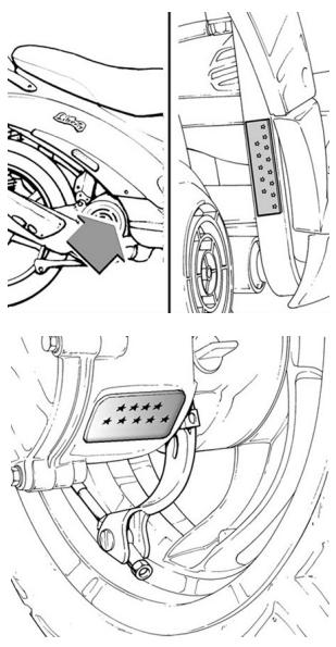
Dimensions and mass
WEIGHT AND DIMENSIONS
| Specification | Desc./Quantity |
| Dry weight | 88 Kg |
| Width | 670 mm |
| Length | 1.930 mm |
| Wheel base | 1.330 mm |
| Seat height | 775 mm. |
Engine
ENGINE
| Specification | Desc./Quantity |
| Engine type | Piaggio Hi-PER2, 2-stroke, single-cylinder |
| Bore x stroke | 40 x 39,3 mm |
| Displacement | 49,40 cm³ |
| Compression ratio | 10,3 :1 |
| Carburettor | DELLORTO PHVA 17,5 |
| CO adjustment | 3,5% ± 0,5 |
| Engine idle | 1800 ÷ 2000 g/min. |
| Air filter | Sponge, impregnated with mixture (50% Selenia Air Filter Oil and 50% lead-free fuel). |
| Starter system | starter motor/kick-start. |
| Lubrication | Guaranteed by oil from fuel-oil mixture and varied |
| with engine speed and throttle opening through a pump driven by the crankshaft via toothed belt. |
| Fuel system | Gravity, unleaded petrol (minimum octane number 95), through carburettor. |
| Cooling system | forced air |
Transmission
| TRASMISSIONS |
| Specification | Desc./Quantity |
| Transmission | Expanding pulley type automatic speed variator with vee belt, automatic clutch and gear final drive. |
Capacities
| CAPACITY |
| Specification | Desc./Quantity |
| Rear hub oil | Quantity : ~ 85 cc |
| Mixer oil | 1.2 litres |
| Fuel tank | 6 litres (including 1-litre reserve) |
Electrical system
Frame and suspensions
| ELECTRICAL COMPONENTS |
| Specification | Desc./Quantity |
| Ignition type | capacitive discharge electronic ignition with incor- porated high-voltage coil. |
| Ignition advance variable, with microprocessor (before T.D.C.) | Fixed 17° ± 1 |
| Reccomended spark plug | CHAMPION RGN2C |
| Battery | 12V-4Ah |
| Main fuse | 7,5 A |
| Generator | In alternate current with three-second output |
FRAME AND SUSPENSION
| Specification | Desc./Quantity |
| Type | Welded steel pipes with pressed sheet metal stiff-ening |
| Front suspension | mechanical telescopic steering tube |
| Front suspension stroke | 66,8 mm |
| Trail | 100 mm |
| Rear suspension | Single double-acting hydraulic shock absorber with coaxial spiral spring. Engine-frame mount by swinging arm. |
| Rear suspension bump position | 70 mm |
Brakes
BRAKE
| Specification | Desc./Quantity |
| Front brake | 220 mm disc brake with hydraulic linkage (r.h. brake lever). |
| Rear brake | drum brake (Ø 140 mm) with mechanical linkage.(l.h. brake lever). |
Wheels and tyres
WHEELS AND TYRES
| Specification | Desc./Quantity |
| Front tyre | Tubeless 90/80-16" |
| Front wheel rim | Die-cast aluminium alloy 2.15 x16" |
| Rear tyre | Tubeless 110/80-14" |
| Rear wheel rim | Die-cast aluminium alloy 2.75 x14" |
| Tyre pressure (front wheel) | 2 bar |
| Tyre pressure (rear wheel) | 2,2 bar |
| Tyre pressure (rear wheel driver and luggage) | 2,5 bar |
| N.B. |
CHECK AND ADJUST TYRE PRESSURE WITH TYRES AT AMBIENT TEMPERATURE. ADJUST PRESSURE ACCORDING TO THE WEIGHT OF THE RIDER AND ACCESSORIES.
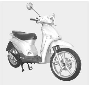
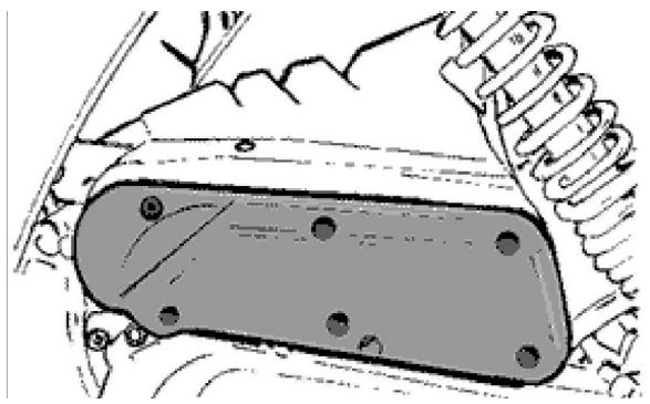
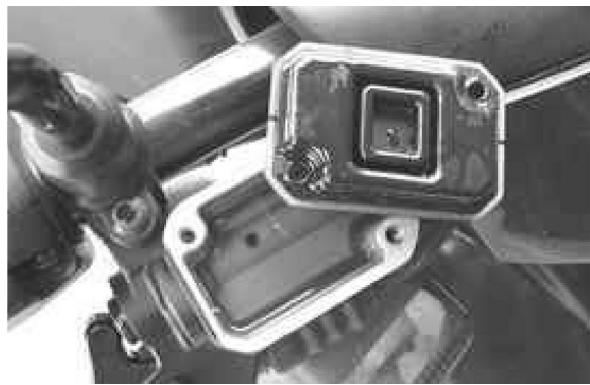
Secondary air
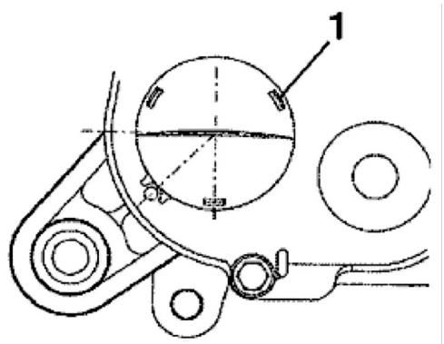
In order to clean the sponge filters of the secondary air system, please proceed as follows:
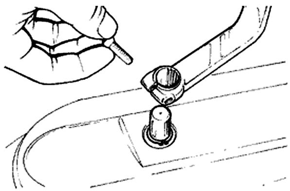
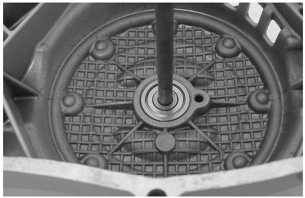
1) Remove the plastic cap (1) from the transmission cover by inserting a small screwdriver through one of the three slits and pressing against the retaining spline, to release it.
2) Wash the polyurethane sponge filter with soap and water, then dry it with compressed air and relocate it in its housing. Refit the intake cover minding the angle reference.
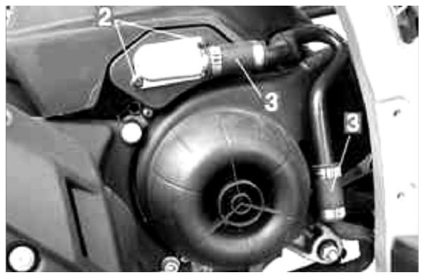
3) Loosen the two screws (2) fixing the SAS aluminium cover in order to reach the polyurethane sponge located inside the box; clean the sponge as indicated in 2) and refit each component, after having in the meantime ensured that the steel plate is not deformed or unable to guarantee a perfect sealing when shut; replace if necessary.
N.B.
WHEN REFITTING THE VALVE COMPONENTS, ENSURE TO CORRECTLY PLACE THE STEEL LATH IN THE HOUSING MACHINED ON THE PLASTIC AND ALUMINIUM COVERS.
CAUTION
DURING THE OPERATION 3) ALWAYS CHECK THE LEAK TIGHTNESS OF THE TWO RUBBER SLEEVES (3) LOCATED AT THE END OF THE SECONDARY AIR DUCT; REPLACE IF NECESSARY; USE NEW ZIP TIES.
Carburettor
50cc Version
Dell'Orto
DELLORTO CARBURETTOR
| Specification | Desc./Quantity |
| Type | PHVA 17,5 RD |
| Choke diameter | Ø 17,5 |
| Adjustments reference number | 8423 |
| Maximum thrust: | 53 |
| Maximum air thrust (on body): | Ø1,5 |
| Tapered pin stamping: | A22 |
| Needle position (notches from top): | 1 |
| Jet mixer: | 209 HA |
| Minimum thrust: | 32 |
| Minimum air thrust (on body): | Free |
| Initial minimum mixture screw opening: | 1 1/2 |
| Starter jet | 50 |
| Starter air thrust (on body) | Ø 1,5 |
| Starter pin stroke | 11 mm |
| Choke maximum cone | Ø 1,5 |
Overhaul data
Assembly clearances
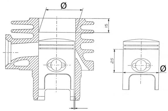
Cylinder - piston assay.
CONNECTION PISTON AND CYLINDER
| Name | Play | Initials | Cylinder | Piston | Play on fitting |
| Cylinder | ∅40+0,033+0,005 | M | 40,005 - 40,012 | 39,943 - 39,95 | 0,055 - 0,069 |
| Cylinder | ∅40+0,033+0,005 | N | 40,012 - 40,019 | 39,95 - 39,957 | 0,055 - 0,069 |
| Piston | ∅40-0,029-0,057 | O | 40,019 - 40,026 | 39,957 - 39,964 | 0,055 - 0,069 |
| Piston | ∅40-0,029-0,057 | P | 40,026 - 40,033 | 39,964 - 39,971 | 0,055 - 0,069 |
| Cylinder first uprat | ∅40+0,033+0,005 | M1 | 40,205 - 40,212 | 40,143 - 40,15 | 0,055 - 0,069 |
| Cylinder first uprat | ∅40+0,033+0,005 | N1 | 40,212 - 40,219 | 40,15 - 40,157 | 0,055 - 0,069 |
| Piston first up- | ∅ | O1 | 40,219 - | 40,157 - | 0,055 - 0,069 |
| rat. | 40-0,029-0,057 | | 40,226 | 40,164 | |
| Piston first up-rat. | Ø | P1 | 40,226 - 40,233 | 40,164 - 40,171 | 0,055 - 0,069 |
| Cylinder second uprat. | Ø | M2 | 40,405 - 40,412 | 40,343 - 40,35 | 0,055 - 0,069 |
| 40+0,033+0,005 |
| Cylinder second uprat. | Ø | N2 | 40,412 - 40,419 | 40,35 - 40,357 | 0,055 - 0,069 |
| 40+0,033+0,005 |
| Piston second uprat. | Ø | O2 | 40,419 - 40,426 | 40,357 - 40,364 | 0,055 - 0,069 |
| 40-0,029-0,057 |
| Piston second uprat. | Ø | P2 | 40,426 - 40,433 | 40,364 - 40,371 | 0,055 - 0,069 |
| 40-0,029-0,057 |
Piston rings
UPRATING TABLE
| Name | Dimensions | Initials | Quantity |
| Compression lining | 40 | A | 0,10 ÷ 0,25 |
| Compression lining 1° greater | 40,2 | A | 0,10 ÷ 0,25 |
| Compression lining 2° greater | 40,4 | A | 0,10 ÷ 0,25 |
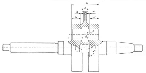
Crankcase - crankshaft - connecting rod
END PLAY BETWEEN DRIVING SHAFT AND CONNECTING ROD
| Name | Dimensions | Initials | Quantity |
| Connecting rod | 11,750-0,05 | A | E = 0,25 ÷ 0,50 |
| Packing washer | 0,5 ± 0,03 | G | E = 0,25 ÷ 0,50 |
| Half shaft transmission side | 13,75+0,040 | C | E = 0,25 ÷ 0,50 |
| Half shaft flywheel side | 13,75+0,040 | D | E = 0,25 ÷ 0,50 |
| Spacing tool | 40,64 | H | E = 0,25 ÷ 0,50 |
| Cage | 11,80-0,35 | B | F = 0,20 ÷ 0,75 |
| Packing washer | 0,5 ± 0,03 | G | F = 0,20 ÷ 0,75 |
| Half shaft transmission side | 13,75+0,040 | C | F = 0,20 ÷ 0,75 |
| Half shaft flywheel side | 13,75+0,040 | D | F = 0,20 ÷ 0,75 |
| Spacing tool | 40,64 | H | F = 0,20 ÷ 0,75 |
Slot packing system
- Fit the cylinder without positioning the base gasket
- Position a dial gauge on the special tool and zero it on rectified surface.
- Fix the tool on the top of the cylinder using two nuts to fix it to the studs and then bring the piston to T.D.C.
- The gasket thickness to be adopted varies with the measurement. For this reason gaskets with three different thicknesses are available as
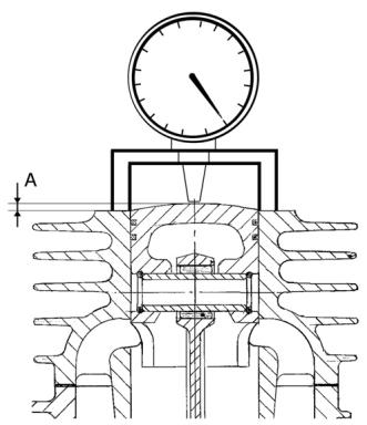
spares.
020272Y Tool for checking the position of the piston
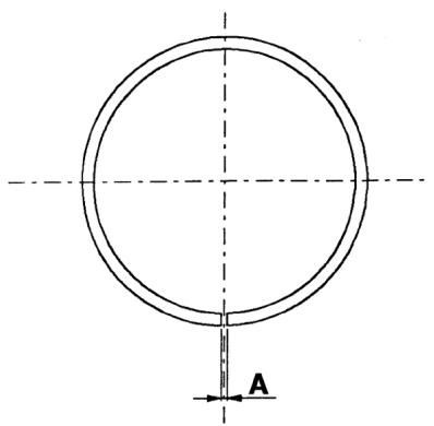
PACKING SYSTEM
| Name | Measure A | Thickness |
| Packing | 2,80 ÷ 3,04 | 0,4 |
| Packing | 3,04 ÷ 3,24 | 0,6 |
| Packing | 3,25 ÷ 3,48 | 0,8 |
Products
TABLE OF RECOMMENDED PRODUCTS
| Product | Description | Specifications |
| TUTELA ZC 90 | Rear hub oil | SAE 80W/90 Oil that passes API GL3 specifications |
| SELENIA HI Scooter 2 Tech | Oil for flexible transmission lub-rication (acceleration control, mixer and km counter) | Oil for two-stroke motors |
| SELENIA Air Filter Oil | Oil for air filter sponge | Mineral oil with specific additive for ingreasing the ISO VG 150 |
| SYSTEM TW 249 AREXONS | Grease (brake/acceleration command levers) | Compound calcium soap grease NGLI 1-2 |
| SELENIA HI Scooter 2 Tech | Mixer Oil | Synthetic oil that passes API TC ++ specifications |
| TUTELA TOP 4 | Brake fluid | Synthetic fluid SAE J1703, NHTSA 116 DOT 4, ISO 4925 |
| MONTBLANC MOLYBDENUM GREASE | Grease for driven pulley shaft compensating ring and mobile driven pulley sliding seat | Molybdenum bisulphide grease |
| TUTELA ZETA 2 | Grease for steering, seats of pin and swing arm | Lithium soap and zinc oxide grease NLG12 |
| TUTELA MRM2 | Grease for driven pulley bushing and mobile driven pulley seat | Bisulphide soap grease with Mo-lybdenum NLGI2 |
INDEX OF TOPICS
TOOLING
ATT
TOOLS
| Stores code | Description |
| 001330Y | Steering seat installer, to be fitted with parts: 001330Y009-For lower seat, 001330Y013-For upper seat |
| 001467Y006 | 20-mm pliers |
| 001467Y007 | Bell for bearings external Ø 54 mm |
| 001467Y009 | Bell for bearings external Ø 50 mm |
| 001467Y013 | 15-mm pliers |
| 001467Y014 | 15 mm pliers |
| 001467Y017 | Bell for bearings external Ø 39 mm |
| 001467y021 | 11 mm bearing clip |
| 002465Y | Pliers for snap rings |
| 006029y | Drift for fitting thrust ring seats on steering tube |
| 020004Y | Drift for removing thrust rings from steering head tube |
| 020055Y | Steering tube ring nut spanner |
| 020150Y | Support for air heater "METABO HG 1500/2" |
| 020151Y | Air heater "METABO HG 1500/2" |
| 020162y | Flywheel extractor |
| 020163y | Crankcase splitting plate |
| 020164y | Half-pulleys fixing sheath |
| 020165y | Starter sprocket retainer |
| 020166y | Piston rings fixing tool |
| 020261Y | Kick-starter spring assembler |
| 020262Y | Crankcase detachment plate |
| 020265y | Bearing fitting stand |
| 020325y | Pliers for brake-shoe springs |
| 020329Y | Pump MITYVAC |
| 020330Y | Stroboscopic gun for two- and four-stroke engines |
| 020331Y | Digital multimeter |
| 020332Y | Digital rpm counter |
| 020333Y | Single battery charger |
| 020334Y | Multiple battery charger |
| 020335Y | Magnetic stand and comparator |
| 020350y | Electric system diagnostic device |
| 020357Y | 32 x 35 mm adaptor |
| 020359Y | 42 x 47 mm hub bearing fitting adaptor |
| 020376Y | Handle for punches |
| 020412Y | 15 mm guide |
| 020456Y | Ø 24 mm adaptor |
| 020483Y | 30 mm guide |
| 020487Y | Fork oil seal removing tool |
| 020565Y | Compass flywheel stop spanner |
| 494929 | Exhaust gas analyser |
INDEX OF TOPICS
MAINTENANCE
MAN
Maintenance chart
EVERY2 YEARS
Action
Brake fluid - Change
AT 1000 KM OR 4 MONTHS
Action
Hub Oil - Replacement
Oil mixer/throttle linkage - Adjust
Speedometer cable - Grease
Steering - Adjust
Brake levers - Grease
Brake fluid level - Check
Nuts, bolts and fasteners - Check
Electrical system and battery - Check
Tires-inflation and wear - Check
Vehicle and brake test - Road test
AT 5000 KM OR 12 MONTHS, 25000 KM, 35000 KM AND 55000 KM
Action
Hub oil level - Check
Spark plug/Electrode gap - Change
Air filter - cleaning
Oil mixer/throttle linkage - Adjust
Brake levers - Grease
Brake pads - Check condition + wear
Brake fluid level - Check
Electrical system and battery - Check
Tires-inflation and wear - Check
Vehicle and brake test - Road test
AT 10000 KM OR 24 MONTHS AND 50000 KM
Action
Hub Oil - Replacement
Spark plug/spark gap - replacement
Air filter - cleaning
Idle speed/Fuel (^*) - Adjust
Action
| Oil mixer/throttle linkage - Adjust |
| Variator rollers - Change |
| Speedometer cable - Grease |
| Transmission Belt - Check |
| Steering - Adjust |
| Brake levers - Grease |
| Brake pads - Check condition + wear |
| Brake fluid level - Check |
| Transmissions - Lubricate |
| Nuts, bolts and fasteners - Check |
| Suspensions - Check |
| Electrical system and battery - Check |
| Headlight - Adjust |
| Tires-inflation and wear - Check |
Vehicle and brake test - Road test
(*) See CO regulation in the «Adjusting the engine idle» section
AT 15000 KM AND 45000 KM
Action
AT 20000 KM AND 40000 KM
| Hub oil level - Check |
| Spark plug/spark gap - replacement |
| Air filter on carburetor - Clean |
| Oil mixer/throttle linkage - Adjust |
| Transmission Belt - Replacemen |
| Brake levers - Grease |
| Brake pads - Check condition + wear |
| Brake fluid level - Check |
| Electrical system and battery - Check |
| Tires-inflation and wear - Check |
| Vehicle and brake test - Road test |
| SAS box (sponge) (**)- Clean |
SAS suction cap (sponge) (^**) - Clean
(**) See rules in the «Secondary Air System» section
Action
AT 30000 KM
| Hub Oil - Replacement |
| Spark plug/Electrode gap - Change |
| Air filter - cleaning |
| Idle speed/Fuel (*) - Adjust |
| Cylinder cooling system - Check/Clean |
| Oil mixer/throttle linkage - Adjust |
| Transmission Belt - Check |
| Variator rollers - Change |
| Fule-oil mixer belt - Change |
| Speedometer cable - Grease |
| Steering - Adjust |
| Brake levers - Grease |
| Brake pads - Check condition + wear |
| Brake fluid level - Check |
| Transmissions - Lubricate |
| Nuts, bolts and fasteners - Check |
| Suspensions - Check |
| Electrical system and battery - Check |
| Headlight - Adjust |
| Tires-inflation and wear - Check |
| Vehicle and brake test - Road test |
| (*) See CO regulation in the «Adjusting the engine idle» section |
Action
| Hub Oil - Replacement |
| Spark plug/spark gap - replacement |
| Air filter - cleaning |
| Idle speed/Fuel (*) - Adjust |
| Oil mixer/throttle linkage - Adjust |
| Transmission Belt - Check |
| Transmission Belt - Replacemen |
| Variator rollers - Change |
| Speedometer cable - Grease |
| Steering - Adjust |
Action
AT 60000 KM
| Brake levers - Grease |
| Brake pads - Check condition + wear |
| Braking circuit hose - Replacement |
| Brake fluid level - Check |
| Transmissions - Lubricate |
| Nuts, bolts and fasteners - Check |
| Suspensions - Check |
| Electrical system and battery - Check |
| Headlight - Adjust |
| Tires-inflation and wear - Check |
| Vehicle and brake test - Road test |
| SAS box (sponge) (**)- Clean |
| SAS suction cap (sponge) (**)- Clean |
| (*) See CO regulation in the «Adjusting the engine idle» section (**). See rules in the «Secondary Air System» section |
Action
| Hub Oil - Replacement |
| Spark plug/spark gap - replacement |
| Air filter - cleaning |
| Idle speed/Fuel (*) - Adjust |
| Cylinder cooling system - Check/Clean |
| Oil mixer/throttle linkage - Adjust |
| Transmission Belt - Check |
| Transmission Belt - Replacemen |
| Variator rollers - Change |
| Fule-oil mixer belt - Change |
| Speedometer cable - Grease |
| Steering - Adjust |
| Brake levers - Grease |
| Brake pads - Check condition + wear |
| Braking circuit hose - Replacement |
| Brake fluid level - Check |
| Transmissions - Lubricate |
| Nuts, bolts and fasteners - Check |
Action
| Suspensions - Check |
| Electrical system and battery - Check |
| Headlight - Adjust |
| Tires-inflation and wear - Check |
| Vehicle and brake test - Road test |
| SAS box (sponge) (**)- Clean |
| SAS suction cap (sponge) (**)- Clean |
| (*) See CO regulation in the «Adjusting the engine idle» section (**). See rules in the «Secondary Air System» section |
Carburettor
Disassemble all carburettor components, accurately wash them in solvent, then dry them with compressed air. To ensure thorough cleaning, pay special attention to the passages in the carburettor body.
- Carefully check the condition of all components.
- The throttle must slide freely in the chamber, if the play is excessive because or wear, replace the throttle.
- Replace the carburettor if the chamber shows signs of wear as to prejudice the valve's regular seal or free sliding (though it is new).
- When reassembling the carburettor, it is a good rule to replace the gaskets.
WARNING
PETROL IS HIGHLY EXPLOSIVE. ALWAYS FIT NEW SEALS AND GASKETS TO PREVENT LEAKAGE.
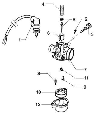
- Automatic choke device - 2. Idle air adjusting screw - 3. Idle adjusting screw - 4. Throttle valve spring - 5. Conical needle - 6. Throttle valve - 7. Carburettor body - 8. Needle - 9. Idle jet - 10. Float - 11. Main jet - 12. Float bowl.
Checking the spark advance
- The check must be carried out at over 4,000 rpm with a strobe light. The spark advance must be 17^ before the T.D.C.
- This value is correct when the reference mark shown on the flywheel cover is aligned with that machined on the cooling fan and the phase-shifter on the strobe light is set onto 17^ .
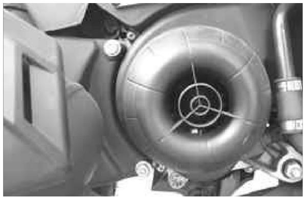
N.B.
IN THE EVENT OF IRREGULAR OPERATION, PERFORM THE CHECKS LISTED IN THE ELECTRICAL CIRCUIT CHAPTER.
CAUTION
BEFORE PERFORMING THE ABOVE MENTIONED INSPECTIONS, CHECK THE FLYWHEEL IS CORRECTLY KEYED ONTO THE CRANKSHAFT
020330Y Stroboscopic gun for two- and four-stroke engines
Spark plug
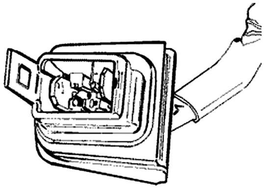
-Rest the vehicle on its centre-stand;
-Remove the central flap, shown in the figure, by loosening the two fixing screws;
-Detach the H.T. cable cap from the spark plug;
-Remove the spark plug using the supplied box spanner;
-Examine the spark plug conditions, the insulator integrity, and measure the spark gap using a suitable feeler gauge;
-Proceed by adjusting the spark gap by carefully bending the outer electrode.
If defective, replace the spark plug with new of the prescribed model;
- Insert the spark plug in with the correct inclination, screwing it in by hand, hence tighten it using
the supplied box
-spanner at the prescribed torque; -Reattach the
spark plug cap; -Refit the central flap.
CAUTION
THE SPARK PLUG REMOVAL MUST BE CARRIED OUT WITH THE ENGINE COLD. THE SPARK PLUG MUST BE REPLACED EVERY 5,000 KM. THE USE OF NON APPROVED ELECTRONIC IGNITION DEVICES OR SPARK PLUGS OTHER THAN THE PRESCRIBED MODEL MAY SERIOUSLY DAMAGE THE ENGINE.
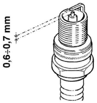
Characteristic
Reccomended spark plug
CHAMPION RGN2C
Electric characteristic
Electrode gap
0,6÷ 0,7mm
Locking torques (N^*m)
Spark plung 25 - 30 Nm
Hub oil
Check
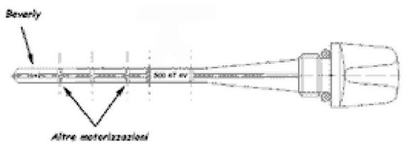
A new hub oil dipstick (item no. 832019) has been introduced. This dipstick differs from the previous one in that it is 5 ~mm longer and has a cube on the lower end with a dot at the centre of two of its four side faces. Such dot is the reference for the engine oil level check on the Beverly; (see figure).
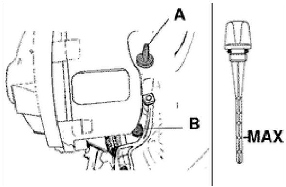
To check the correct oil level, proceed as follows:
1) Place the vehicle on the stand on level ground.
2) Unscrew oil dipstick «A», wipe it with a clean rag, reinsert it and screw it in fully.
3) Pull out the dipstick and check that the oil level
is in the middle (two-notch dipstick) or reaches the middle notch (three-notch dipstick).
4) Reinsert the dipstick and screw it in fully.
Recommended products
TUTELA ZC 90 Rear hub oil
SAE 80W/90 Oil that passes API GL3 specifications
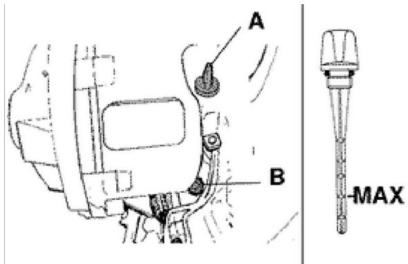
Replacement
- Remove the oil filler cap «A».
- Loosen the oil draining cap «B» and let the oil completely drain the tank.
- Tighten the draining cap and refill the hub with oil (approx. 75 cc).
Air filter
- Remove the cleaner plug by unloosing the 6 fixing screws. Remove the filtering element.
Cleaning:
-Wash with water and neutral soap.
-Dry with a clean cloth and small jets of compressed air.
-Soak with a 50% fuel/oil mixture.
- Let the filtering element drain and then squeeze it with your hands without crushing it.
- Let it dry and refit it. Mineral oil with special additives to increase its adhesiveness ISO VG 150
CAUTION
NEVER RUN THE ENGINE WITHOUT THE AIR FILTER, THIS WOULD RESULT IN AN EXCESSIVE WEAT OF THE PISTON AND CYLINDER
Recommended products
Selenia Air Filter Oil Air filter sponge oil
Mineral oil with specific additives to increase ad
hesion ISO VG 150
Checking the ignition timing
-Adjust the control cables:
Mixer cable: see "Mixer timing" procedure, below.
Throttle cable: adjust the screw on the carburettor so that there is no play on the sheath.
Splitter control cable: adjust the screw on the
throttle grip on the handlebar so that there is no play on the twist grip.
All cables must be adjusted so that there is no play on their sheaths.
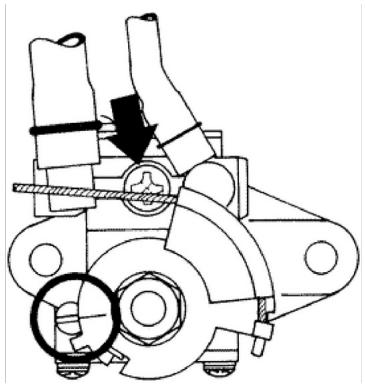
Mixer timing
- Adjust via the transmission screw on the crank-case, with the throttle cable released, the reference machined on the rotating plate which must be aligned to that shown on the mixer body as indicated in the figure. While performing this operation the engine must be fed with a 2% oil-fuel mixture (at least 0.5 litres if the tank is empty).
CAUTION
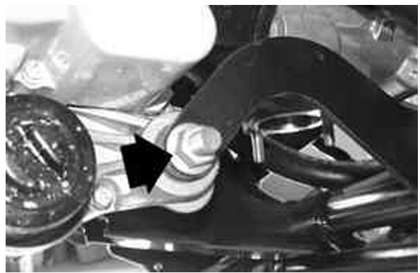
WHEN RUNNING OUT OF OIL OR REMOVING THE OIL TANK, FOLLOW THE MIXER BLEEDING OPERATIONS AS FOLLOWS: REFILL THE OIL TANK, WITH THE MIXER FITTED ONTO THE ENGINE, AND THE ENGINE NOT RUNNING, DETACH THE MIXER TUBE FROM THE CARBURETTOR AND LOOSEN THE BLEED SCREW (SEE ARROW IN FIGURE) UN- TIL OIL STARTS FLOWING OUTWARDS. RECON- NECT THE INLET TUBE TO THE CARBURETTOR, FIXING IT WITH THE APPROPRIATE METALLIC CLAMP.
Recommended products
SELENIA HI Scooter 2 Tech Mixer Oil
Synthetic oil that passes API TC ++ specifications
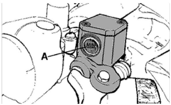
Braking system
Level check
Proceed as follows:
- Rest the vehicle onto its centre-stand and align the handlebars;
- Check the liquid level through the inspection hole «A».
A certain decrease in the liquid level is due to the wear of the pads.
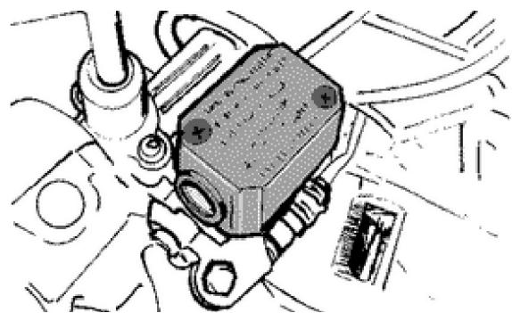
Top-up
Use the following procedure:
Loosen the two screws, remove the reservoir cap, remove the gasket and top up only with the prescribed fluid without exceeding the maximum level.
CAUTION
BRAKE FLUID TYPE TUTELA TOP 4
CAUTION
KEEP THE BRAKE FLUID AWAY FROM THE SKIN, THE EYES AND CLOTHING. IN CASE OF CONTACT, RINSE GENEROUSLY WITH WATER.
CAUTION
THE BRAKE FLUID IS HIGHLY CORROSIVE. TAKE CARE NOT TO SPILL IT ON THE PAINTWORK.
CAUTION
THE BRAKE FLUID IS HYGROSCOPIC, I.E. IT ABSORBS HUMIDITY FROM THE AIR. IF THE HUMIDITY CONTAINED IN THE FLUID EXCEEDS A GIVEN CONCENTRATION, THE BRAKING ACTION BECOMES INSUFFICIENT. NEVER DRAW THE FLUID FROM OPEN OR PARTLY EMPTY CONTAINERS.
UNDER NORMAL CLIMATIC CONDITIONS THE FLUID SHOULD BE RENEWED EVERY 20,000 KM, OR IN ANY CASE EVERY TWO YEARS.
N.B.
CHANGE THE BRAKE FLUID AND BLEED THE SYSTEM AS DESCRIBED IN CHAPTER BRAKING SYSTEM
Recommended products
TUTELA TOP 4 Brake fluid
Synthetic fluid SAE J1703, NHTSA 116 DOT 4, ISO 4925
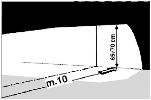
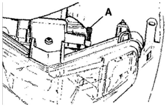
Headlight adjustment
Place the unloaded vehicle on flat ground 10 m away from a half-lit white wall and ensure the vehicle axis is perpendicular to the wall.
Mark a horizontal line on the wall at 65 ÷ 70 cm from the ground.
Start the engine, turn on the headlight and set it on high-beam, then adjust the headlight so that the line separating the lit and the non lit regions stays below the line marked on the wall. To adjust the headlight it is necessary to remove the front top cover (see Bodywork Chapter) and act upon screw «A» located behind the headlight, as shown in the picture.
Before carrying out the adjustment operation, check the tyres are inflated at the prescribed pressure.
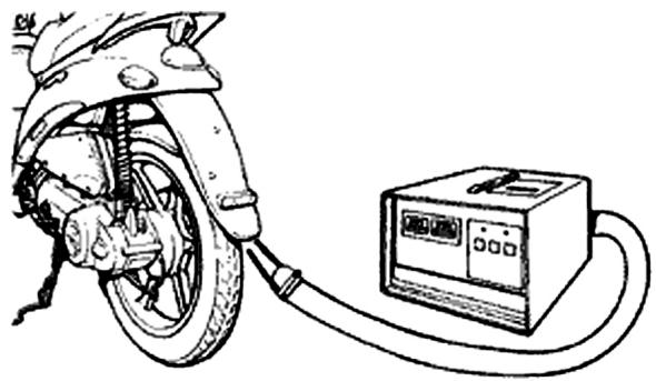
CO check
The check must be carried out after having carefully cleaned all carburettor components, with the air filter clean and the spark plug in good conditions.
1) Warm up the engine riding the vehicle at 45 Km/h for 10 min.; this is necessary to disengage the automatic choke device.
2) Shut down the engine in order to carry out operations 3) and 4).
3) Insert a ~ 50 cm extension duct to the exhaust gas outlet on the silencer.
4) Carefully ensure leak tightness between the exhaust and the duct. Insert the analyser sensor in the duct.
5) Start the engine.
6) Switch on the high-beam.
7) Wait for a few moments, until the idle speed settles.
8) Without ever twisting the throttle and using the appropriate flux screw, bring the engine up to 1800 ± 100 rpm.
9) Adjust the flux screw so to have a "CO" value equal to 3.5% ± 0.5% .
10) Slowly twist the throttle grip until the engine reaches 4,000 rpm, then shut it back down; ensure the idle speed goes back to the initial value, otherwise repeat the operation starting from point (3).
020332Y Digital rpm counter
494929 Exhaust gas analyser
INDEX OF TOPICS
TROUBLESHOOTING
RIC GUA
This section is for finding solutions to solve problems.
A list of possible causes is provided for each problem and related operations.
Engine
POOR PERFORMANCE
| Possible Cause | Work |
| Carburettor jets or fuel cock clogged or dirty | Remove, wash in solvent and dry with compressed air |
| Excessive carbon deposits on cylinder ports and in combustion chamber | Decoke |
| Poor compression: worn compression rings or cylinder | Check parts and replace if necessary |
| Silencer clogged by excessive carbon deposits | Replace silencer and check carburation and mixer timing |
| Air filter clogged or dirty | Clean |
| Choke failure (it remains inserted) | Check mechanical sliding, circuit continuity, power supply, and electrical connections |
| Clutch slippage | Check and if necessary replace the centrifugal weights and/or clutch housing |
| Defective sliding of movable pulleys | Check parts and replace if necessary. Lubricate the driven pulley with Montblanc-Molibdenum Grease (drg. 498345). |
| Worn driving belt | Replace |
| Carburettor jets clogged or dirty | Remove, wash in solvent and dry with compressed air |
| Fuel filter on vacuum cock obstructed | Replace cock filter |
| Worn rollers; presence of oil; dirt | Check presence of the plug with filter on the transmission cover; clean the speed variator; replace worn rollers |
Rear wheel spins at idle
REAR WHEEL
| Possible Cause | Work |
| Idle speed set too high | Adjust slow running speed and C.O, if necessary. |
| Faulty clutch | Check springs/weight of friction and clutch hous- ing pan |
| Air filter box not sealed | Refit filter box. Replace if it is damaged |
Starting difficulties
STARTING DIFFICULTIES
| Possible Cause | Work |
| Carburettor jets clogged or dirty | Remove, wash in solvent and dry with compressed air |
| Fuel cock failure | Check that the fuel comes through the feed pipe when the engine is started, with the throttle closed; if not, replace the vacuum cock |
| Choke failure | Check: electrical connections, circuit continuity, mechanical sliding and power supply |
| Spark plug faulty or electrodes gap incorrect | Check spark plug and electrodes gap. Replace if necessary |
| Battery is down | Check the battery charge condition. If the battery shows signs of sulfation, replace it. Before installing the new battery, charge it for eight hours with a current corresponding to 1/10 of the capacity of the battery |
| Engine flooding | Open the throttle wide and try to start the engine. If the engine does not start, remove the spark plug, run the engine with throttle open making sure the cap is connected to the spark plug and the spark plug is earthed, far from the hole. Fit a dry spark plug and start the engine. |
| Wrong fuel specifications | Drain the fuel and then refuel |
| Spark plug defective | Brush clean and restore the correct gap between electrodes, or replace with a plug of recommended type. Remember that many engine problems are attributable to the use of an unsuitable spark plug |
| Intake manifold cracked or clips not tightened | Renew intake manifold and check sealing on head |
| Cleaner-carburettor union damaged | Replace |
Excessive oil consumption/Exhaust smoke
EXCESSIVE CONSUMPTION
| Possible Cause | Work |
| Excessive carbon deposits on cylinder ports and in combustion chamber | Decoke |
Engine tends to cut-off at full throttle
ENGINE TENDS TO CUT OUT AT FULL THROTTLE
| Possible Cause | Work |
| Maximum jet dirty - lean carburetion | Wash with solvent and dry with compressed air |
| Fuel cock failure | Check that the fuel comes through the feed pipe when the engine is started, with the throttle closed; if not, replace the vacuum cock |
| Water in the carburettor | Empty the basin by the special drain |
| Float valve faulty | Check float sliding and needle valve operation |
| Float valve defective | Check float and needle sliding |
| Fuel vent pipe clogged | Restore the proper tank aeration |
Engine tends to cut-off at idle
ENGINE TENDS TO STOP WHEN IDLING
| Possible Cause | Work |
| Idle nozzle dirty | Wash with solvent and dry with compressed air |
| The choke stays open | Check: electrical connections, circuit continuity, mechanical sliding and power supply |
| The reed valve does not close | Check / replace the reed pack |
| Slow running incorrectly tuned up | Tune up slow running and check C.O. level |
| Spark plug faulty | Replace spark plug with an equivalent part having the prescribed heat grade. Check electrodes gap |
High fuel consumption
EXCESSIVE CONSUMPTION
| Possible Cause | Work |
| Air filter clogged or dirty | Clean |
| Inefficient starter | Check: electric connections, circuit continuity, mechanical sliding, and presence of power |
Excessive exhaust noise
INCREASED EXHAUST NOISE
| Possible Cause | Work |
| Secondary air metal pipeline is worn | Check pipeline sealing on crankcase and box, check presence and correct assembly of plug with filter on transmission cover. |
| Secondary air circuit components faulty | Check components and pipeline, check correct assembly. Replace components if they are damaged |
SAS malfunctions
LOOSENESS OF RUBBER UNION OF SECONDARY AIR TUBE TO SILENCER
| Possible Cause | Work |
| Secondary air reed blocking | Replace |
| Secondary air filter clogged | Clean filter and box |
| Secondary air union to silencer clogged | Decoke the union taking care not to let the carbon deposits fall inside the silencer |
Transmission and brakes
CLUTCH DEFECTIVE
| Possible Cause | Work |
| Jerky or irregular operation | Check that the weights shift and return smoothly. Check that there is no grease on the weights. Check that the contact surface of the clutch weights with the housing is at the centre, and that the 3 weights have the same specifications. Check that the clutch housing is not scored or does not show anomalous signs of wear. Never run the engine without the clutch housing. Check that the plug with filter on the transmission cover is there |
Insufficient braking
BRAKING SYSTEM FAILURE
| Possible Cause | Work |
| Insufficient braking force | The rear brake (drum brake) is adjusted by setting the relative registers (on the wheel), remem-
bering that the wheels must turn freely when the brake levers are fully released.
The braking action should start when brake levers are pulled at 1/3 of their travel.
Check wear of brake pads. If there are problems that cannot be overcome simply by normal adjust-
ment of the control linkages, proceed to inspect the pads and front brake disc, the shoes and the rear drum.
If surfaces are excessively worn or scored, re-
place the affected parts as necessary |
| Air bubbles in the braking hydraulic system | Carefully bleed the hydraulic system (spring ac- |
Possible Cause
Work
| tion of the brake lever should not be felt) |
| Fluid leakage | Spring connections, piston gaskets or brake pump failure. Replace |
| Worn fluid | Change the front brake fluid and restore correct level in the pump |
| Cables not sliding properly in sheaths | Lubricate or replace |
| Noisy brake | Check pads and/or shoes wear |
Brakes overheating
BRAKES OVERHEATING
Possible Cause
Work
| Defective piston sliding | Check the caliper and replace any damaged parts |
| Brake disc or drum deformed | Check by means of a dial gauge the disc level-ness with the wheel correctly mounted, or con-centricity of the rear drum |
Electrical system
Battery
BATTERY
Possible Cause
Work
| Battery | This one component of the system needs checking more frequently and servicing more carefully than any other. If the vehicle is to stand idle for any length of time (one month or longer), the battery will need recharging periodically. The battery discharges completely over a period of around 5 - 6 months. When fitting the battery to the vehicle, take care not to switch the connections: the black earth lead is connected to the negative terminal and the red lead to the positive terminal marked +. To charge the battery, follow the instructions described in Chapter ELECTRICAL EQUIPMENT. |
Steering and suspensions
Rear wheel
REAR WHEEL
| Possible Cause | Work |
| Idle speed set too high | Adjust idle speed. Adjust C.O. if necessary |
| Faulty clutch | Check springs / frictional weights and clutch housing. |
Heavy steering
STEERING STIFF
| Possible Cause | Work |
| Unacceptable tightening | Check the tightening torque of the upper and lower collar.
If the steering fails to turn smoothly even when correctly tightened, inspect the bearing races and replace if they show signs of uneven wear |
Excessive steering play
EXCESSIVE STEERING PLAY
| Possible Cause | Work |
| Excessive steering play | Check the tightening torque of the upper and lower collar.
If the steering fails to turn smoothly even when correctly tightened, inspect the bearing races and replace if they show signs of uneven wear |
Noisy suspension
NOISY SUSPENSION
| Possible Cause | Work |
| Noisy suspension | If the front suspension is noisy, check: efficiency of front suspension; condition of the ball bearings and relative locking nuts; rubber stroke end bumbers; sliding bushes |
Suspension oil leakage
OIL LEAKING FROM SUSPENSION
| Possible Cause | Work |
| Oil leaking from suspension | Check pumping elements and condition of sleeves and sealing rings. Replace if damaged. |
INDEX OF TOPICS
ELECTRICAL SYSTEM
IMP ELE
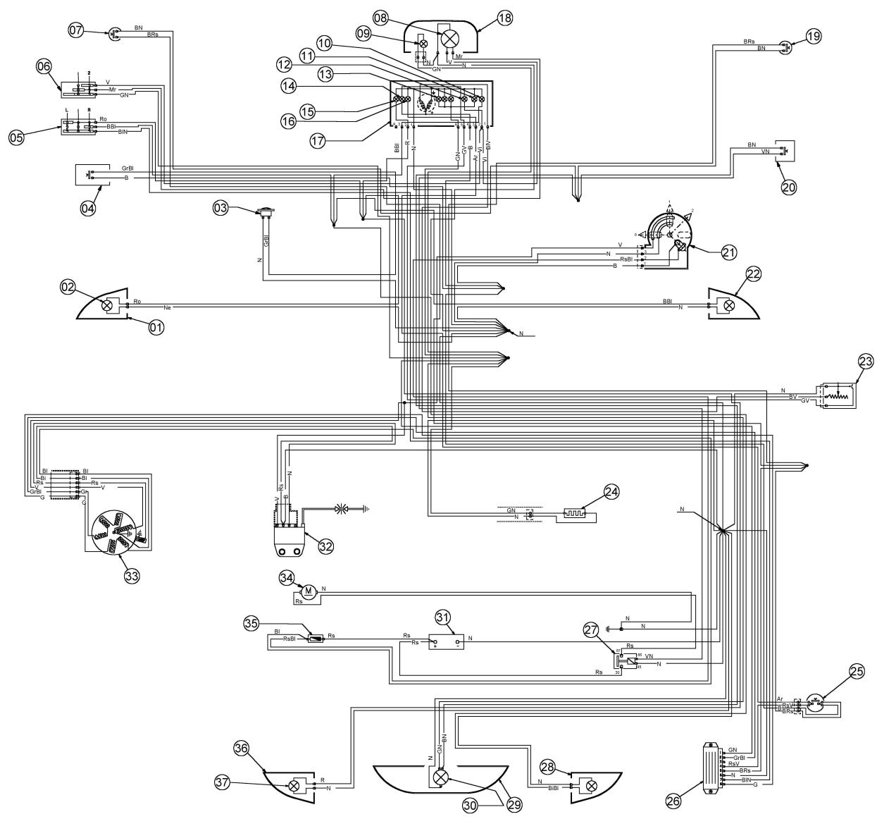
Legend:
- Front LHS turn signal light; 2 light bulbs for each turn signal light
- 2 amber light bulbs for turn signal light
- Horn
- Horn button
- Turn signal switch 6. Headlight switch
- Stop light switch on rear brake
- Light bulb
- Headlight bulb
- RHS turn signal warning light
- Headlamp warning light
- High-beam warning light
-
Instrument panel light bulbs
-
Low fuel warning light
- LHS turn signal warning light
- Low oil warning light
- Odometer level gauges with warning lights, 7 light bulbs
- 2 light bulbs for headlamp
- Stop switch on front brake
- Starter button
- Key-switch
- Front RHS turn signal light
- Fuel level sender
- Automatic choke device
- Mixer oil warning light sender
- Voltage regulator
- Starter relay
- Rear RHS turn signal light
- Taillight assembly
- Stop and taillight bulb
- Battery
- Electronic ignition device (CDI)
- Flywheel magneto
- Starter motor
- Fuse holder with 7.5 A fuse
- Rear LHS turn signal light
- 2 amber light bulbs for turn signal light
Colour coding for electrical wires:
B = White
BI = Blue
G = Yellow
Mr = Brown
N = Black
GN = Yellow-Black
Gr = Grey
Rs = Pink
R = Red
Vi = Purple
V = Green
BN = White-Black
BBI = White-Blue
GV = Yellow-Green
Ar=Orange
GrBI = Yellow-Blue
RsBI = Pink-Blue
BIV = Blue-Green
BRs = White-Pink
Conceptual diagrams
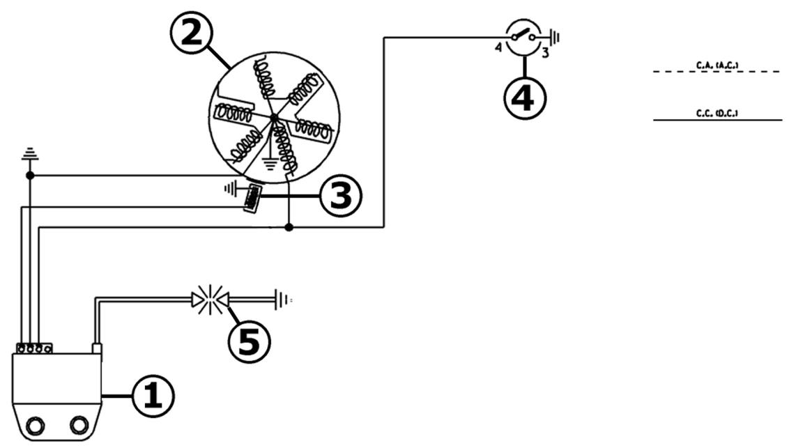
Ignition
IGNITION
| Specification | Desc./Quantity |
| 1 | Electronic controller | |
| 2 | Magneto flywheel | |
| 3 | Pick - up | |
| 4 | Key switch | |
| 5 | Spark plug | |
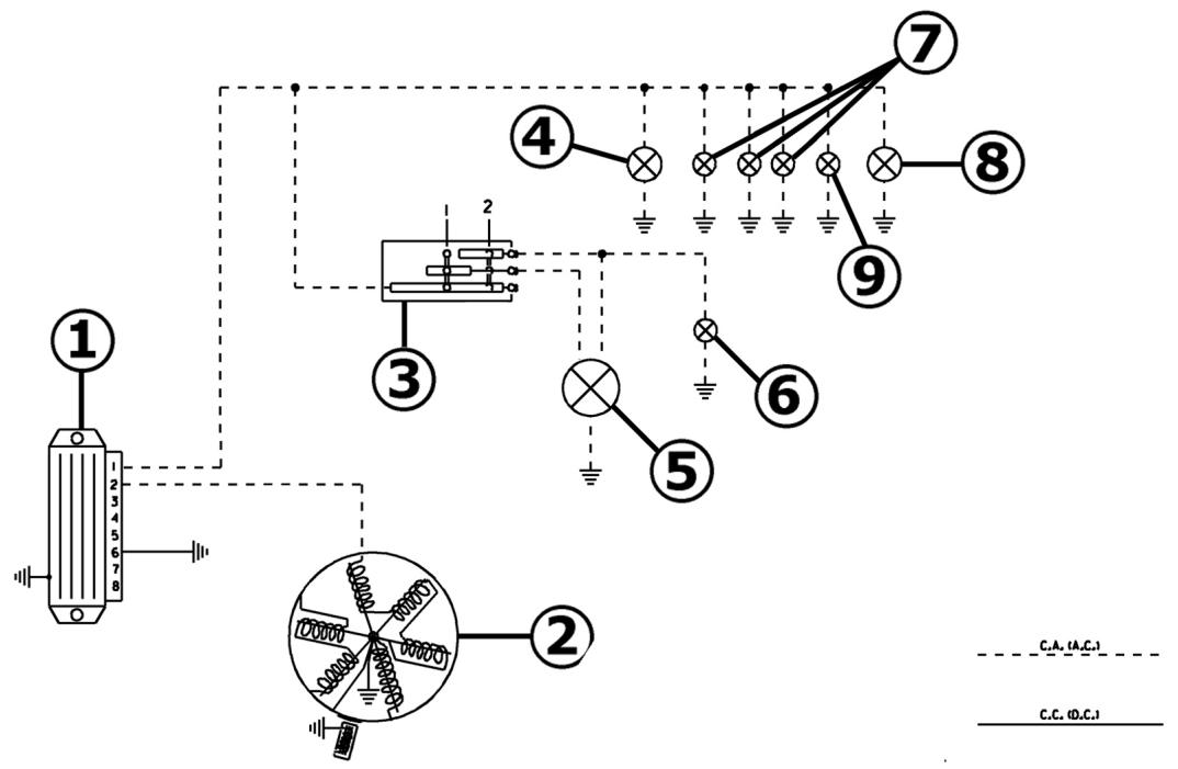
Lights
LIGHTS
| Specification | Desc./Quantity |
| 1 | Voltage regulator | |
| 2 | Magneto flywheel | |
| 3 | Light switch with flash | |
| 4 | Rear light bulb | 12V - 5W |
| 5 | Headlight bulb | 12V-35/35W |
| 6 | High beam warning light bulb | 12V-1,2W |
| 7 | N°3 instrument lighting bulbs | 12V - 1.2W |
| 8 | Taillight bulb | 12V - 5W |
| 9 | Headlight warning light | 12V - 1.2W |
Battery recharge and starting
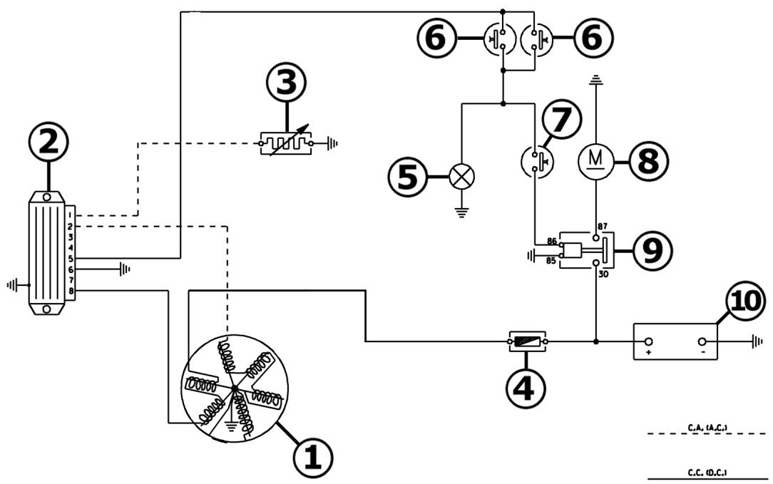
BATTERY RECHARGE AND STARTING SECTION
| Specification | Desc./Quantity |
| 1 | Magneto flywheel | |
| 2 | Voltage regulator | |
| 3 | Automatic starter | |
| 4 | Main fuse | 7,5A |
| 5 | Brake light filament | 12V - 21W |
| 6 | Front and rear brake light button | |
| 7 | Start up button | |
| 8 | Starter motor | |
| 9 | Remote starter switch | |
| 10 | Battery | 12V - 4Ah |
Safety switches
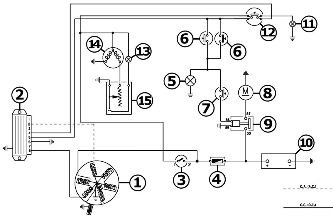
START PERMISSIVE BUTTONS AND LEVEL INDICATORS
| Specification | Desc./Quantity |
| 1 | Magneto flywheel | |
| 2 | Voltage regulator | |
| 3 | Key switch | |
| 4 | Main fuse | 7,5A |
| 5 | Brake light filament | 12V - 21W |
| 6 | Front and rear brake light button | |
| 7 | Start up button | |
| 8 | Starter motor | |
| 9 | Remote starter switch | |
| 10 | Battery | 12V - 4Ah |
| 11 | Stop light bulb | 12V - 1.2W |
| 12 | Oil level sender | |
| 13 | Reserve fuel light | 12V-1,2W |
| 14 | Fuel Level Transmitter | |
| 15 | Fuel level thermistor | |
Turn signal lights
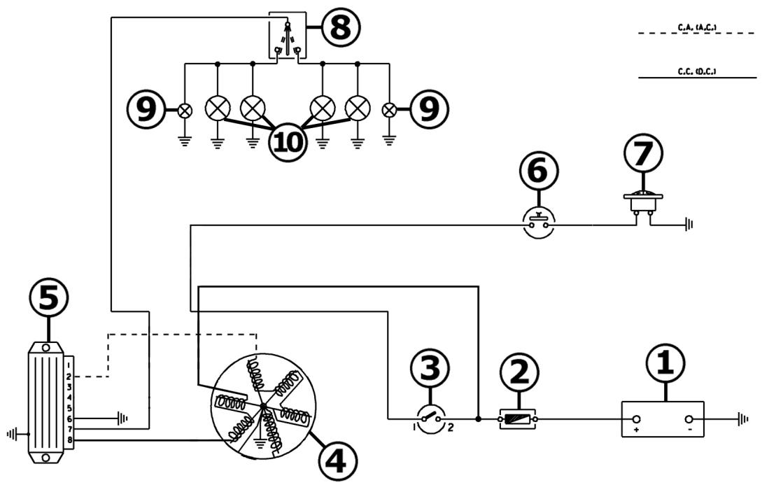
TURN INDICATORS AND HORN
| Specification | Desc./Quantity |
| 1 | Battery | 12V - 4Ah |
| 2 | Main fuse | 7,5A |
| 3 | Magneto flywheel | |
| 4 | Voltage regulator | |
| 5 | Horn button | |
| 6 | Horn | |
| 7 | Indicators switch | |
| 8 | Two (2) turn signal warning light bulbs | 12V - 2W |
| 9 | 4 Turn indicator bulbs | 12V-10W |
| 10 | Key switch | |
Checks and inspections
In case of faulty or failed operation of the ignition system and if the cause cannot be found by a simple visual inspection, replace the C.D.I. module with another of the same type and certainly working.
Remember that the disconnections needed to replace the C.D.I. module are to be carried out
while the engine is switched off.
If the replacement restores the ignition system to
proper operation, the fault is to be found in the
C.D.I. module, which will have to be replaced.
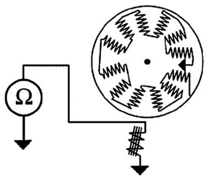
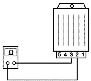
If faulty or failed operation persists, conduct the following checks on the generator and on the stator components:
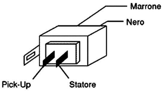
After a visual inspection of the electrical connections, it is possible to perform measurements on the stator winding and pick-up (see table), using the specific multimeter.
If, during the checks on the charge coil and the pick-up, anomalies are found, replace the stator and other faulty parts.
Disconnect the connector on the flywheel housing and measure the resistance between each of the two contacts and the earth.
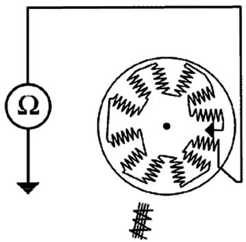
020331Y Digital multimeter
PICK-UP TEST
| Specification | Desc./Quantity |
| 1 | 1) Brown and ground cable | ~ 170 Ω |
| STATOR WINDING CHECK | |
| Specification | Desc./Quantity |
| 1 | 1) Black and ground cable | ~ 1 Ω |
1) No-load test: the starter motor, when unloaded, must absorb no more than 10A with a supply voltage ≥ 12V and must rotate at ≥ 15,000 rpm.
2) Load test: when the starter motor is so braked that it absorbs 47A with supply voltage ≥ 10V , torque of ≥ 0.2 N·m must be obtained at 10,000 rpm.
3) Static torque test: when the rotor is locked and the supply voltage is < 7V , the absorbed current must not exceed 130A and the torque must be at least 0.55 N·m
Specifications
- Rated voltage 12V.
- Rated power 0.25kW
- Left-hand rotation view from pinion side.
- Connected to the engine by pinion and crown wheel on crankshaft, transmission side.
- Push-button control.
- Battery used for the test:12V-3,6Ah.
N.B.
THE ABOVE CHARACTERISTICS MUST BE MEASURED WITH A CHARGED BATTERY AND AFTER RUNNING THE STARTER MOTOR FOR 30 SECONDS IN THE CONDITIONS DESCRIBED AT POINT 1.
Ignition circuit
All checks on the electrical equipment involving the disconnection of cables (checks on ignition circuit connections and devices) are to be carried out while the engine is switched off. Should the engine be running, the C.D.I. module could suffer irreparable damage.
Stator check
- Using a tester check the resistance between the brown-ground and black-ground terminal.
N.B.
THE VALUES ARE STATED FOR AMBIENT TEMPERATURE. CHECKING THE STATOR AT OPERATING TEMPERATURE WILL BRING THE VALUES ABOVE THE STATED ONES.
Electric characteristic
Stator : brown - ground
170 (Pick-Up)
Stator : black-ground
1 (Stator)
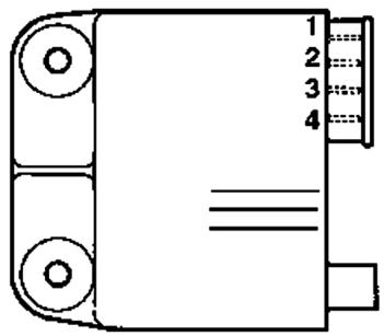
Voltage regulator check
If the voltage regulator is faulty, the following problems may occur depending on the type of regulator malfunction:
1) Bulbs burnt out (regulator in short circuit).
2) The lighting and electrical starter system do not work (regulator interrupted).
3) Battery fails to charge
4) Turn indicators failure
The regulator is provided with earth supplied from the electrical equipment, therefore the regulator body does not supply earth to the internal circuits. Check the insulation between each terminal of the regulator and its body, using the specific tester.
1) BURNING OUT OF BULBS
The regulator must be replaced, as it is certainly faulty.
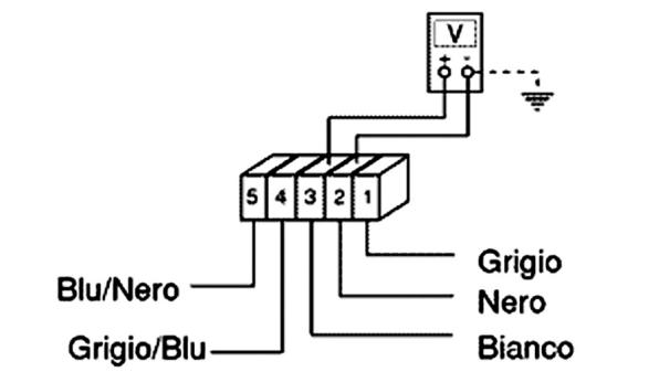
2) LIGHTS AND STARTING DEVICE FAILURE
Expose the voltage regulator by removing the plastic cover from the front shield, start the engine and let it idle. Keep all vehicle lights out.
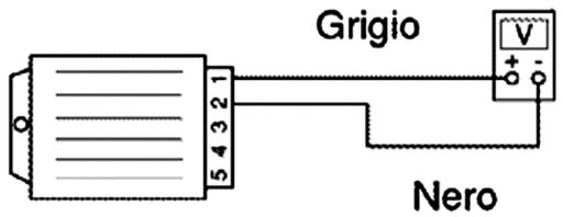
Fit the positive prod of the multimeter (set for measuring alternating voltages) to terminal no. 1 (grey wire) and the negative prod to terminal no. 2 (black wire). Check if voltage is present (see fig-
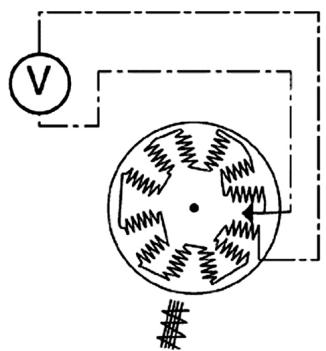
ure).
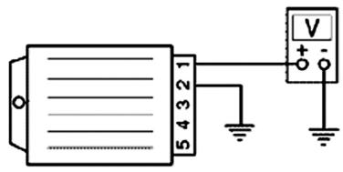
If there is no voltage, fit the negative prod directly on earth; if voltage is measured, check the regulator's earth cables; otherwise replace the regulator because it is certainly broken.
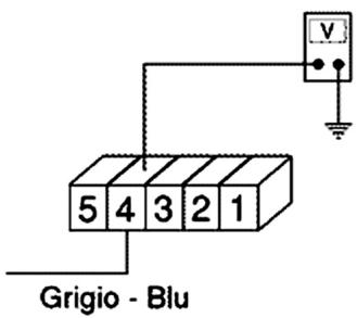
Finally, you may measure the voltage supplied by the stator:
- Disconnect the regulator connector, fit a multimeter between the grey-blue cable (4) and the earth to measure alternate voltages (see figure).
- Voltage delivered at 2000 revs/min shoud be about 25 - 35V.
If also in this case no values are obtained, replace the regulator because it is damaged.
N.B.
FOR THE ABOVE MEASUREMENTS, USE AN ANALOGUE MULTIMETER FOR ALTERNATING VOLTAGES AND KEEP THE ENGINE IDLING SO AS TO OBTAIN AN ALTERNATING VOLTAGE WITH A FREQUENCY AS CLOSE AS POSSIBLE TO 50 HZ AND MEASURE THE ACTIVE TENSION SUPPLIED BY THE REGULATOR (APPROX. 12 V).
12V a 1900÷ 2000 giri/min.
12V a 1900 ÷ 2000 giri/min.
25 ÷ 35 ~V a 1900 ÷ 2000 giri/min.
3)BATTERY FAILS TO CHARGE
A fault on the direct current section of the regulator can result in the following problems, depending on the type of fault:
a) Blowing of the protecting fuse due to an overvoltage condition (regulator shorted) preventing the battery from being recharged.
b) Battery fails to recharge (regulator circuit interrupted).
Interventions
a) Fuse blow (regulator short-circuited).
Check that the wiring that connects the protecting
8 M
fuse to the ignition switch is not damaged, which would cause a short circuit to earth and rule out possible regulator damage; if the related fuse blows only after the ignition switch has been turned to "ON" and if the regulator connector is detached, check that the wiring and devices following the ignition switch are not shorted to earth. Measure the resistance between contacts 3 (White) and 2 (Black) on the voltage regulator (the connector must be disconnected).
The resistance should be approximately 8 MW. If the measurement differs greatly from the prescribed value, the regulator is shorted and needs to be replaced.
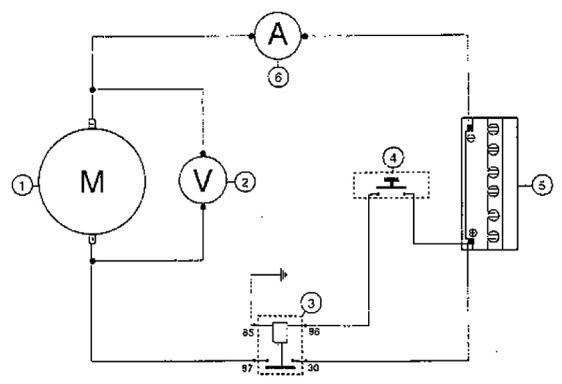
b) Battery fails to recharge (regulator circuit interrupted).
To check the voltage regulator recharge section, first connect 2 multimeters (one to measure the voltage and the other one to measure the current) as shown in the second figure and use the following procedure:
Start the engine (temporarily connect the red cable to the positive terminal to avoid damaging the instrument).
Check that voltage is at least 13V while engine is idling (battery charged), and that the recharge current is 1.5 - 2A with lights off. By increasing the engine revs number, the recharge voltage and current progressively increase, at speeds higher than 4000 revs/min. the recharge current should be about 4.5A; by turning on the lights, the stoplight and using the horn, the current values may be ≥ 5A and the voltage value 14 - 14.5V (regulator threshold value).
If different values are obtained, replace the
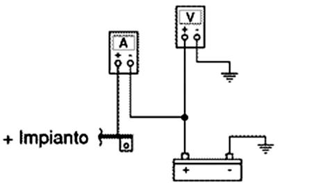
2000 giri/min 1,3V / 1,5÷ 2A >4000 giri/min 14÷ 14,5V > 4A
regulator, otherwise check the wires and connections.
Electric characteristic
Replace the regulator since
8 M
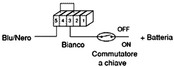
4) TURN INDICATORS FAIL TO OPERATE In case of turn indicators fault, proceed as follows:
-
Remove the regulator connector and insert the multimeter prods between white wire (3) and black wire (2).
-
Turn the key switch to ON and check that the battery is powered. If no voltage is measured, repeat the test between the earth and white cable. If the check is still unsuccessful, check the cables and the contacts on the key switch and battery. If the battery voltage is measured, check the regulator earth cables (black cable)
-
If the above checks are successful, jump contacts 5 (blue/black) and 3 (white) on the connector, turn the key switch to ON and turn the flashlights switch to the left and to the right to check if lights goes on (these are directly fed by the battery).
If the flashlights do not go on, check the cables and the switch operation; otherwise, replace the regulator since it is faulty.
020331Y Digital multimeter
Sealed battery
Putting a sealed battery into service If the vehicle is equipped with a sealed battery, servicing is lim
ited to checking the charge level and, if necessary, recharging the battery.
These operations must be performed during predelivery, and every six months of open-circuit storage.
Therefore, in addition to checking and, if necessary, charging the battery before delivery, it is necessary to carry out these operations before storing the vehicle, and subsequently every six months.
RECHARGING THE BATTERY FOLLOWING OPEN-CIRCUIT STORAGE
1) Checking the voltage
Before installing the battery on the vehicle, measure the open-circuit voltage with an ordinary multimeter.
- If the voltage exceeds 12.60V , the battery can be installed without recharging.
- If the voltage is less than 12.60V , recharge the battery as described at item 2).
2) Constant-voltage charging method
- Constant voltage: 14.40-14.70 V
- Initial charging current: 0.3 - 0.5 × rating
- Charging time:
- Recommended 10-12 hrs
Minimum 6 hrs
Maximum 24 hrs
3) Constant-current charging method
- Initial charging current: 1/10 of rating
- Charging time: Maximum 5 hrs
WARNING
WHEN THE BATTERY IS DEEPLY DISCHARGED (FAR BELOW 12.6V), 5 HOURS' RECHARGING MAY NOT BE ENOUGH TO OBTAIN OPTIMUM PERFORMANCE. IN THESE CONDITIONS, HOWEVER, TO AVOID DAMAGING THE BATTERY BEYOND
REPAIR, IT IS ESSENTIAL NOT TO RE-CHARGE IT FOR MORE THAN 8 CONSECUTIVE HOURS.
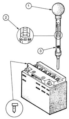
1 hold the tube upright
2 visually check the level
3 the float must be released
Dry-charge battery
1) - Remove the short closed tube and the plugs. Fill the cells to the upper level with battery acid, specific gravity 1.26 corresponding to 30^ Bé at 15^ C.
2) - Leave the battery to stand for about 2 hours and then top up once again with battery acid.
3) - Within 24 hours, recharge the battery using the specific battery charger 020333Y (single) or 020334Y (multiple). Apply an intensity equivalent to about 1/10 of the battery rating until the acid density is approximately 1.27, corresponding to 31^ Bé, and these values stabilize.
4) - When the battery is fully charged, top up with distilled water, refit the plugs and clean the battery case.
5) - After completing the above operations, proceed to install the battery on the vehicle, taking care to observe the connections between the wiring and the battery terminals.
WARNING
AFTER INSTALLING THE BATTERY AND IN ORDER TO PROVIDE A VENT FOR THE GASES FORMING INSIDE IT, REPLACE THE SHORT CLOSED TUBE NEXT TO THE POSITIVE (+) TERMINAL WITH THE CORRESPONDING LONG OPEN TUBE WHICH IS PRESENT ON THE VEHICLE. CHECK THAT THE TUBE SLOTS ARE TURNED TO THE BATTERY SIDE
020333Y Single battery charger
020334Y Multiple battery charger
The battery is the electrical component which requires the most constant care and accurate maintenance. The main maintenance rules are as follows:
1) Checking the electrolyte level
Frequently check that the electrolyte reaches the upper level. To top up, only use distilled water. If you need to top up the battery too frequently, check the vehicle electrical equipment as the battery is certainly working in overload conditions, which will lead to rapid deterioration.
2) Checking the battery charge
After restoring the electrolyte level, check its density with the special hydrometer (see figure).
When the battery is charged, electrolyte density must be between 30 and 32 Bé, corresponding to specific gravity of 1.26-1.28 at a temperature not lower than 15^ .
If density has fallen below 20^ Bé, the battery is completely discharged and needs recharging.
At the end of the charging, check the level and density of the electrolyte in each cell. If the vehicle is not used for some time (1 month or more) the battery must be periodically recharged.
In three months the battery runs down completely.
When reinstalling the battery on the vehicle, take care not to invert the connections. The black (-) earth wire must be connected to the negative (-) terminal whereas the two red (+) wires must be connected to the positive (+) terminal.
Normal bench charging must be carried out with the specific battery charge (single) or (multiple).
Choose the charger setting corresponding to the type of battery to be recharged. Ensure you connect up to the battery with the correct polarity (+ to + and - to -). The plugs must be removed from the battery throughout the charging procedure.
4) Cleaning the battery
Keep the battery clean, especially the top; coat the terminals with Vaseline.
WARNING
BEFORE CHARGING THE BATTERY REMOVE ALL CELL PLUGS. KEEP FREE FLAMES OR SPARKS AWAY FROM THE BATTERY DURING RECHARGE.
WHEN THE BATTERY HAS TO BE REMOVED FROM THE VEHICLE, DISCONNECT THE NEGATIVE TERMINAL FIRST.
CAUTION
NEVER USE FUSES HAVING A GREATER CAPACITY THAN THE ONE RECOMMENDED. THE USE OF A FUSE OF UNSUITABLE CAPACITY MAY RESULT IN SERIOUS DAMAGE TO THE WHOLE VEHICLE OR EVEN CAUSE A FIRE.
CAUTION
NORMAL DRINKING WATER CONTAINS SALTS THAT ARE HARMFUL FOR BATTERIES. USE ONLY DISTILLED WATER.
CAUTION
TO ENSURE MAXIMUM PERFORMANCE THE BATTERY MUST BE CHARGED BEFORE USING THE VEHICLE.
INSUFFICIENT BATTERY CHARGE OR LOW ELECTROLYTE LEVEL WHEN FIRST USED WILL RESULT IN PREMATURE FAILURE OF THE BATTERY.
020333Y Single battery charger
020334Y Multiple battery charger
WARNING
BATTERY ELECTROLYTE IS POISONOUS AND CAN CAUSE SERIOUS BURNS AS IT CONTAINS SULPHURIC ACID. AVOID CONTACT WITH THE EYES, THE SKIN AND GARMENTS. IN CASE OF CONTACT WITH THE EYES OR SKIN RINSE ABUNDANTLY WITH WATER FOR ABOUT 15 MINUTES AND SEEK IMMEDIATE MEDICAL ASSISTANCE.
IF THE LIQUID IS INGESTED IMMEDIATELY DRINK LARGE QUANTITIES OF WATER OR MILK. SUBSEQUENTLY DRINK MILK OF MAGNESIA, BEATEN EGG OR VEGETABLE OIL. CALL A DOCTOR WITHOUT DELAY.
BATTERIES PRODUCE EXPLOSIVE GASES. KEEP AWAY OPEN FLAMES, SPARKS AND CIGARETTES. WHEN A BATTERY IS CHARGED IN CLOSED PLACES ENSURE ADEQUATE VENTILATION.
ALWAYS PROTECT THE EYES WHEN WORKING IN THE PROXIVITY OF BATTERIES. POSITION THE TUBE BETWEEN THE MUDGUARD AND THE FILTER. KEEP OUT OF REACH OF CHILDREN.
Connectors
Dashboard
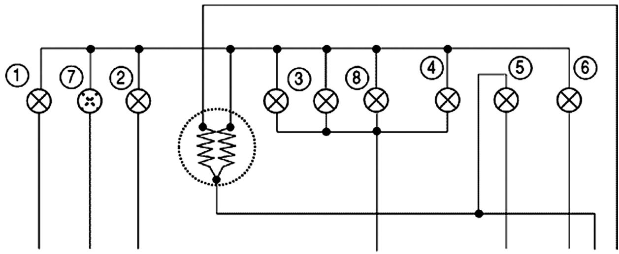
INSTRUMENT PANEL
| Specification | Desc./Quantity |
| 1 | left turn indicator warning light | 12V-2W |
| 2 | High beam warning light bulb | 12V-1,2W |
| 3 | Instrument panel lighting bulb | 12V-1,2W |
| 4 | Headlight warning light | 12V - 1.2W |
| 5 | Reserve fuel light | 12V-1,2W |
| 6 | Right turn indicator warning light | 12V-2W |
| 7 | Available warning light | |
| 8 | Instrument panel lighting bulb | 12V-2W |
INDEX OF TOPICS
ENGINE FROM VEHICLE
MOTVE
Exhaust assay. Removal
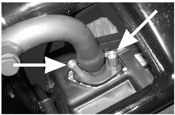
- Remove the two nuts securing the manifold to the head
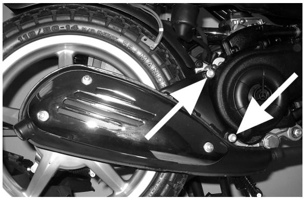
- Unscrew the two screws securing the silencer to the crankcase then remove the complete muffler paying attention to the interference between its support bracket and the cooling casing.
Removal of the engine from the vehicle Reassembling engine to frame
Perform the disassembly steps in reverse order. Observe the prescribed tightening torques.
Locking torques (N^*m)
Swing-arm/engine hinge nut 33 ÷ 41 Engine/shock absorber 33 ÷ 41 ~N · m
Removing the engine/connecting arm pivot pin
Remove the nut shown in the figure and then withdraw the pin.
Removing the engine/shock absorber pivot pin
Remove the nut shown in the figure and then withdraw the pin.
Disassembling engine from frame
- Disconnect the battery.
- Disassemble the complete exhaust unit.
- Remove the rear wheel.
- Disassemble the rear brake linkage.
- Disconnect the electrical terminals.
- Disassemble the throttle and mixer control cables.
- Disconnect the pipelines (fuel - oil - vacuum tap control).
WARNING
HANDLE PETROL WITH THE UTMOST CARE.
CAUTION
WHEN INSTALLING THE BATTERY ALWAYS CONNECT THE POSITIVE LEAD BEFORE THE NEGATIVE LEAD.
WARNING
WEAR PROTECTIVE GOGGLES WHEN USING HAMMERING TOOLS.
INDEX OF TOPICS
ENGINE
MOT
Automatic transmission
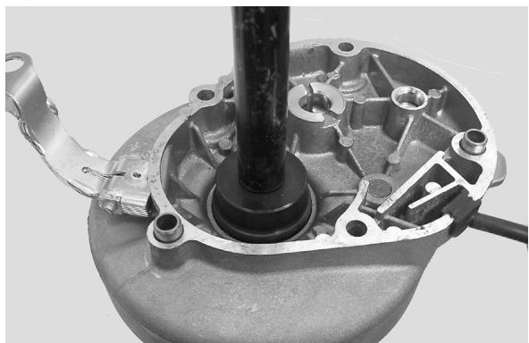
Transmission cover
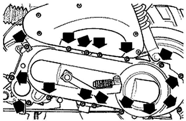
- Loosen the 15 screws and remove the transmission cover with the aid of a mallet.
N.B.
THE CRANKCASE IS RESTRAINED BY THE TIGHT FITTING BETWEEN THE SHAFT OF THE DRIVEN HALF-PULLEY AND THE BEARING HOUSED ONTO THE CRANKCASE.
Kickstart
- Remove the screw shown in the figure and detach the kick-start lever.
- When refitting, follow the above operations in the reverse order, tightening the screw to the prescribed torque.
Locking torques (N^*m)
Kick-start lever replacement: 12 ÷ 13 N·m
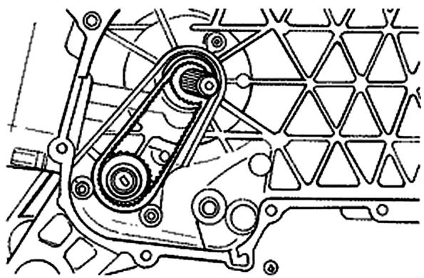
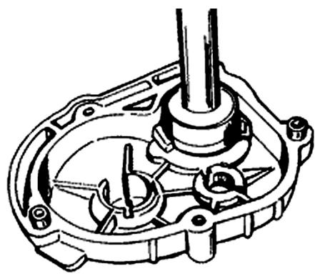
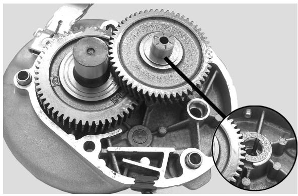
- Remove the split ring positioned on the external side of the transmission cover.
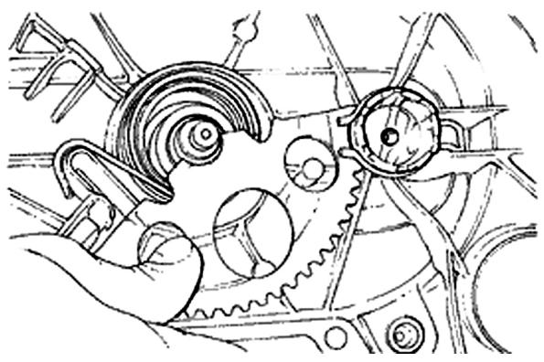
- Remove the drive gear from its housing, decreasing the tension that the toothed segment applies via the spring; to do so, it is necessary to slightly rotate the toothed segment (see figure).
CAUTION
WHEN REMOVIDING THE GEAR, PAY PARTICULAR ATTENSION TO THE LOADING OF THE SPRING AS THIS MAY BE DANGEROUS FOR THE OPERATOR.
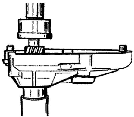
- During the reassembly, apply some of the re
commended grease on the bushing, the spring, and the toothed segment.
- To load the spring, use the special tool as shown in the figure.
- Refit the split ring after checking its condition.
020261Y Kick-starter spring assembler
Recommended products
JOTA 3 FS Speedometer transmission
Lithium soap grease NLGI 33
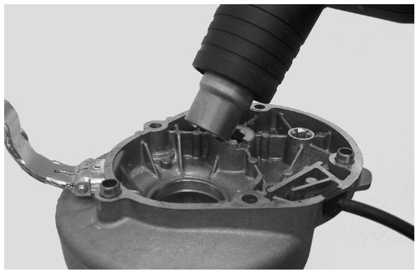
Removing the driven pulley shaft bearing
- Slightly heat the crankcase on the inside to avoid damaging the painted surface. Remove the bearing using the driven pulley shaft or a pin of the same diameter.
N.B.
IF THIS IS DIFFICULT A GENERIC 8 MM EXTRACTOR FOR INNER PARTS CAN BE USED.
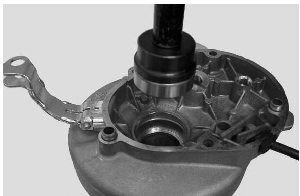
Refitting the driven pulley shaft bearing
- After slightly heating the crankcase on the inside, fit the bearing using a bush of the same diameter as the bearing outer race.
N.B.
WHEN REFITTING, ALWAYS REPLACE THE BEARING WITH A NEW ONE.
CAUTION
WHEN REMOVIDING/REFITTING THE BEARING, TAKE CARE NOT TO DAMAGE THE PAINTED SURFACE.
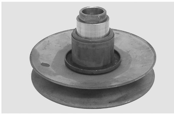
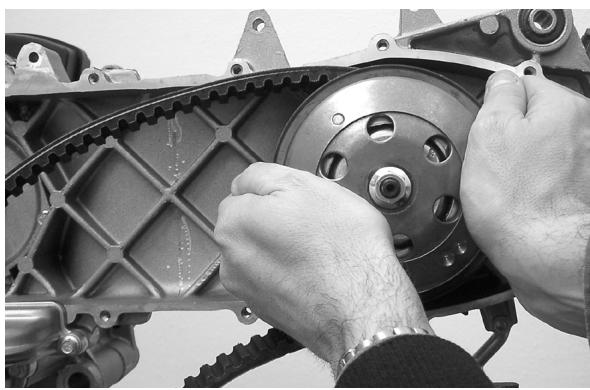
Removing the driven pulley
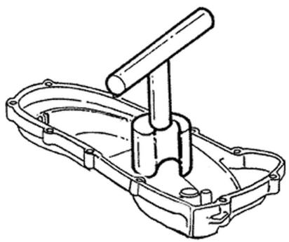
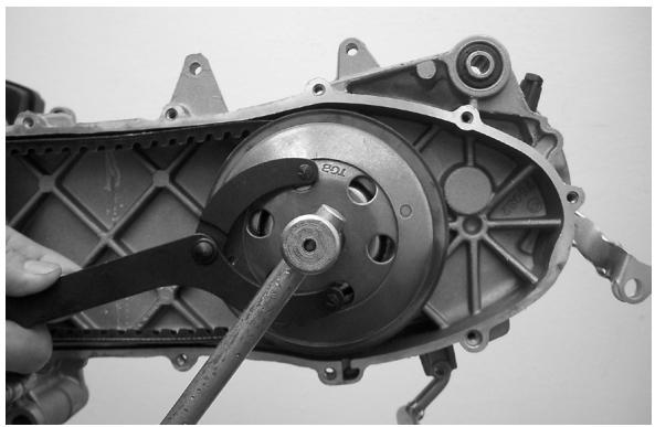
- Lock the clutch bell housing with the specific tool.
- Remove the nut, the clutch bell housing and the
whole of the driven pulley assembly.
N.B.
THE ASSEMBLY CAN ALSO BE REMOVED WITH THE DRIVE PULLEY IN PLACE.
Specific tooling
020565Y Compass flywheel stop spanner
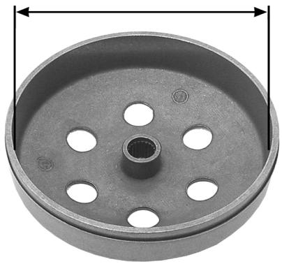
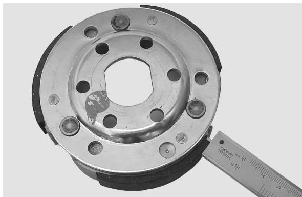
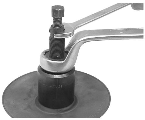
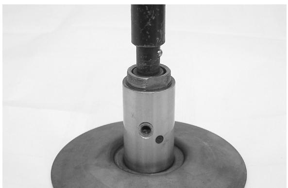
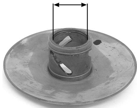
Inspecting the clutch drum
- To verify that the bell clutch is not usurata or damaged.
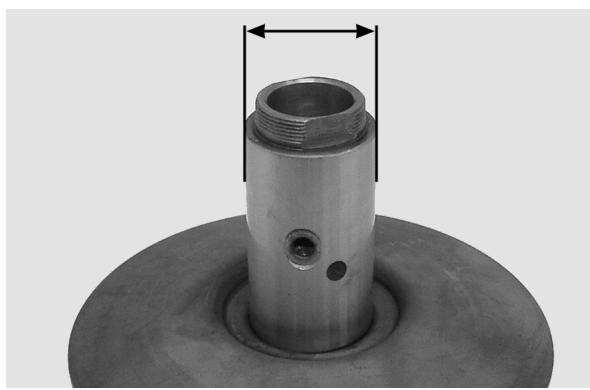
- To measure the inner diameter of the bell clutch.
Characteristic
Clutch bell diameter/standard value
0 107+0,2 +0 mm
Clutch bell diameter/max. value allowed after use
0 107,5 mm
Found eccentricity /max.
0,20 mm
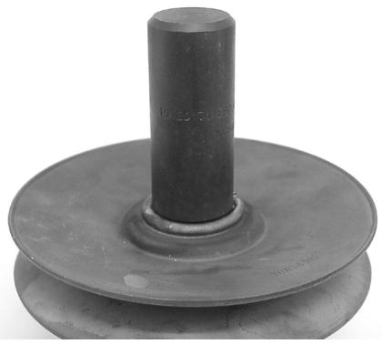
Removing the clutch
- Fit the tool with the long pins screwed on from the outside in positions «A». Insert the driven pulley assembly into the tool and tighten the central screw.
CAUTION
OVERTIGHTENING OF THE CENTRAL SCREW CAUSES THE DISTORTION OF THE TOOL.
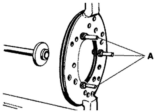
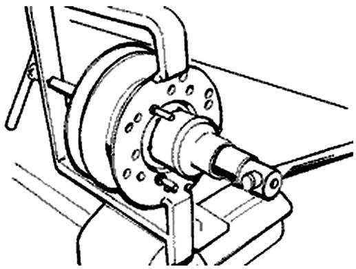
- Using a 34 mm socket wrench, remove the clutch locknut.
- Loosen the central screw, unloading the spring
of the driven pulley assembly.
020444Y Driven half pulley spring compressor tool
Inspecting the clutch
- Check the thickness of the clutch mass friction material.
- The masses must exhibit no traces of lubricants; in that case, check the driven pulley unit seals.
N.B.
UPON RUNNING-IN, THE MASSES MUST EXHIBIT A CENTRAL CONTACT SURFACE AND MUST NOT BE DIFFERENT FROM ONE ANOTHER.
DIFFERENT CONDITIONS MAY CAUSE THE CLUTCH TEARING.
CAUTION
DO NOT OPEN THE MASSES USING TOOLS TO PREVENT A VARIATION IN THE RETURN SPRING LOAD.
Characteristic
Check. Minimum thickness
1 mm
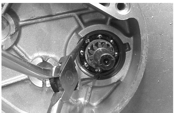
Pin retaining collar
- Remove the collar with the aid of two screw-drivers.

- Remove the three guide pins and the movable half pulley.
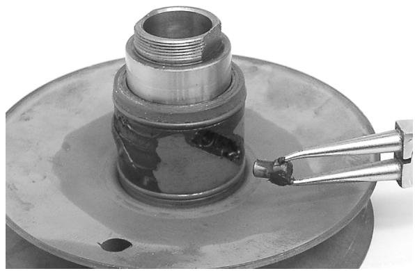
Removing the driven half-pulley bearing
- Remove the roller bearing using the specific extractor inserted from the lower side of the stationary half pulley
CAUTION
POSITION THE SEALING EDGE OF THE EXTRAC- TION PLIERS BETWEEN THE END OF THE BEAR- ING AND THE BUILT-IN SEAL RING.
001467y029 Bell
- Remove the snap ring from the roller bearing.
- Remove the roller bearing from the side of the clutch using the specific device.
N.B.
ADEQUATELY SUPPORT THE HALF PULLEY TO PREVENT THE DRIVE BELT SLIDING SURFACE FROM BEING DISTORTED.
020376Y Handle for punches
020363Y 20mm guide
Inspecting the driven fixed half-pulley
- Make sure there are no signs of wear on the work surface of the belts, if there are replace the half pulley.
- Make sure the bearing do not show signs of unusual wear.
- Measure the external diameter of the pulley bushing.
Characteristic
Standard diameter
033,965÷33,985mm
Stationary driven half pulley/ Minimum diameter allowed after use
033,96 mm
Inspecting the driven sliding half-pulley
- Remove the two inner seal rings and the two O-rings.
- Measure the inside diameter of the movable half pulley bushing.
Characteristic
Maximum allowable diameter
034,08mm
- Check the belt contact surfaces.
- Insert the new oil guards and O-rings on the mobile half pulley.
- Assemble the half pulley on the bushing.
Recommended products
TUTELA MRM 2 Grease for the phonic wheel turning ring
Molybdenum disulphide grease and lithium soap
- Make sure the pins and collar are not worn, reassemble the pins and collar.
- Use a greaser with a curved spout to lubricate the driven pulley unit with around 6 gr. of grease, this operation must be carried out through one of the holes inside the bushing until grease comes out of the opposite hole. This operation is necessary to avoid the presence of grease beyond the O-rings.
Recommended products
TUTELA MRM 2 Grease for the phonic wheel turning ring
Molybdenum disulphide grease and lithium soap
Refitting the driven half-pulley bearing
- Fit a new ball bearing with the specific tools.
- Fit the ball bearing circlip.
- Fit the new roller bearing so that the lettering is visible from the outside.
CAUTION
ADEQUATELY SUPPORT THE HALF PULLEY TO AVOID DAMAGING THE THREADED END WHILE FITTING THE BEARINGS.
020376Y Handle for punches
020456Y Ø 24 mm adaptor
020362y 12 mm guide
020171y Roller bearing drift
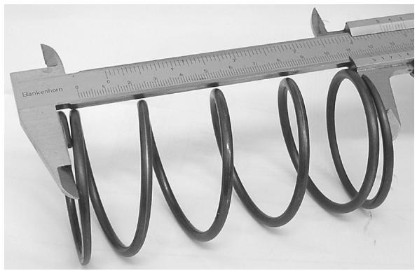
Inspecting the clutch spring
- Make sure that the driven pulley contrast spring is not deformed.
- Minimum length allowed after use
Characteristic
Standard length
118mm
Limit after use
XXXX
Refitting the clutch
- Preassemble the driven pulley unit with spring, sheathing and clutch.
- Position the spring with the plastic shielding supporting the clutch
- Insert the parts in the device and preload the spring, being careful not to damage the plastic sheathing and the end of the threaded shank.
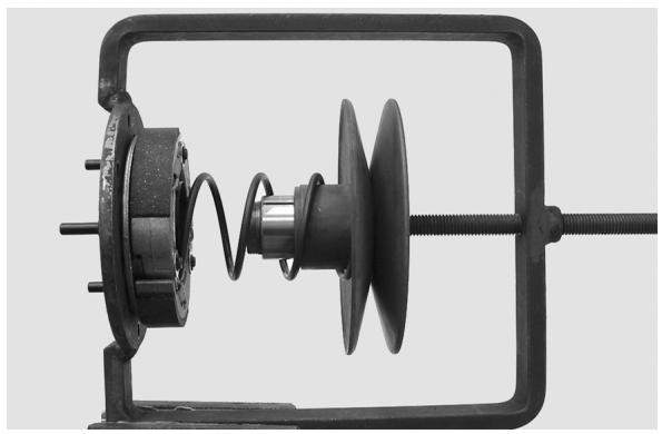
- Reassemble the nut securing the clutch and tighten to the prescribed torque.
CAUTION
TO AVOID DAMAGING THE CLUTCH NUT, USE A SOCKET WRENCH WITH A SMALL BEVEL.
CAUTION
POSITION THE UNBEVELLED SURFACE OF THE NUT IN CONTACT WITH THE CLUTCH.
Locking torques (N^*m)
Nut locking clutch assembly on pulley 55 ÷ 60 Nm
Refitting the driven pulley
- Fit the driven pulley assembly, the clutch bell housing and the nut using the specific tool.
020565Y Compass flywheel stop spanner
Locking torques (N^*m)
Driven pulley shaft nut 40 ÷ 44 Nm
Drive-belt
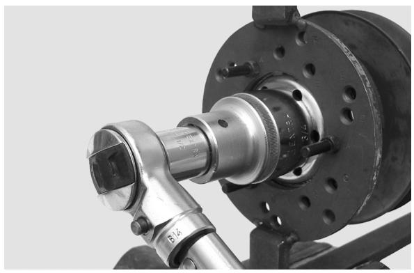
- Make sure the transmission belt is not damaged and does not have cracks in the toothed grooves.
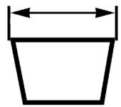
- Check the width of the belt.
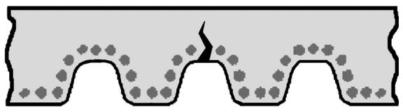
Characteristic
transmission belt/Minimum width
17,5 mm
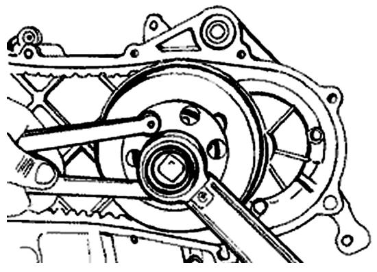
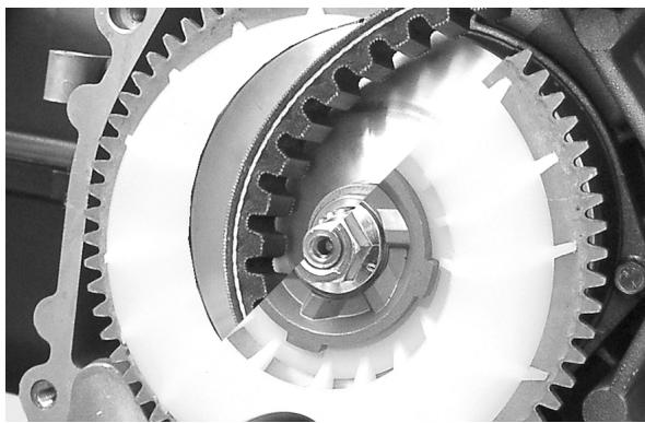
Removing the driving pulley
- Lock the pulley with the specific tool.
- Remove the central nut with the related washer, then remove the drive and the plastic fan.
- Remove the fixed half pulley.
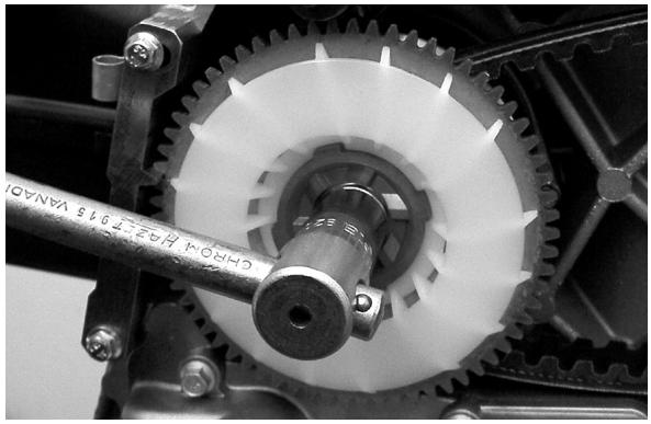
- Remove the belt, washer and remove the mobile half pulley with its bushing, being careful of the rollers and contrast plate fitted loosely on it.
020451y Drive pulley stop spanner
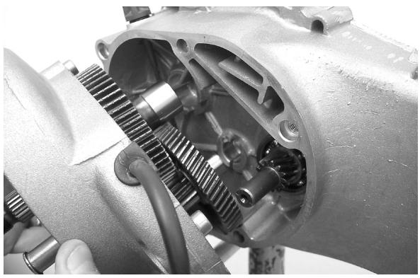
Mixer gears and belt
CAUTION
DO NOT TWIST THE BELT
CAUTION
DO NOT TWIST OR BEND THE BELT WHEN REFITTING IT
CAUTION
BEFORE REFITTING THE BELT, CAREFULLY LUBRICATE THE PIN AND THE MIXER DRIVE GEAR BUSHING WITH OIL, MAKING SURE THIS IS FREE FROM ANY LOAD.
N.B.
REPLACE THE BELT EVERY 20,000 KM.
Recommended products
CONSTANT GLY 2100 product description
oil
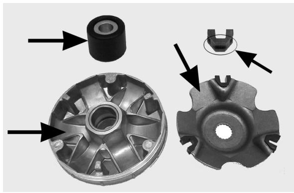
Inspecting the rollers case
1) Make sure that the bushing and sliding rings on the mobile pulley are not lined or deformed.
2) Check the track where the rollers slide on the contact pulley, there should not be any signs of wear and check the conditions of the belt contact surfaces on the half pulleys (mobile and stationary).
3) Make sure that the rollers do not have marked facing on the sliding surfaces and that the metal insert does not protrude from the edges of the plastic cover.
4) Make sure that the contact plate sliding blocks are intact.
CAUTION
DO NOT LUBRICATE OR CLEAN THE BRONZE BUSHING.
Characteristic
Maximum allowable diameter:
20,12 mm
Standard diameter:
20,021 mm
Sliding pulley brass/ Diameter maximum:
XXX mm
Sliding pulley brass/ Standard diameter:
XXX mm
Refitting the driving pulley
- Manually move the mobile driven pulley by pulling it towards the clutch unit and insert the belt keeping the rotation direction of the first assembly.
N.B.
IT IS ALWAYS A GOOD IDEA TO FIT THE BELT SO THAT THE WORDS ARE LEGIBLE IN CASE THE BELT DOES NOT SHOW AN ASSEMBLY DIRECTION.
- Reassemble the unit parts (roller housing unit with bushing, washer, stationary half pulley, belt cooling fan with intake, washer and nut).
- Tighten the nut to a torque of 20 Nm and then finally tighten 90^ with the specific tool preventing rotation of the drive pulley.
N.B.
REPLACE THE NUT WITH A NEW ONE EVERY TIME THE PARTS ARE REASSEMBLED
CAUTION
IT IS VERY IMPORTANT THAT WHEN THE DRIVE PULLEY IS SECURED THAT THE BELT IS FREE INSIDE IT, TO AVOID INCORRECTLY TIGHTENING IT WITH LATER DAMAGE TO THE ENGINE SHAFT MM SCALE.
Specific tooling
020451y Drive pulley stop spanner
Locking torques (N^*m)
Tightening torque plus angle 18 ÷ 20 + 90^ N.m
End gear
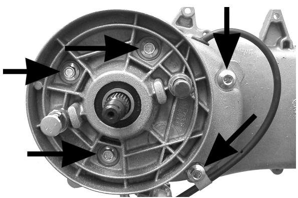
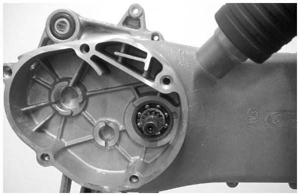
Removing the hub cover
- Drain the oil from the rear hub
- Remove the driven pulley
- Remove the rear brake shoes
- Remove the 5 screws securing the cover to the chassis
- Remove the cover including the wheel axle and extract it
- Remove the intermediate gear with related shear rings
Removing the wheel axle bearings
- Remove the oil guard and seeger ring
- Adequately support the hub cover to avoid damaging the seal surface with the chassis
- Remove the wheel axle bearing with the specific
tool
Specific tooling
020363Y 20mm guide
020376Y Handle for punches
020477Y Adapter 37 mm
Removing the driven pulley shaft bearing
- Remove the seeger ring
- Heat the engine chassis, avoid aiming hot air at the bearing
- Remove the driven pulley shaft with the bearing by hitting it a few time with a mallet
- Remove the bearing from the driven pulley shaft with the specific tool and a gripper
N.B.
USE THE SPECIFIC TOOL FROM THE SIDE WITH A SMALLER INNER DIAMETER
Specific tooling
020452y Driven pulley shaft fitting/removing tube
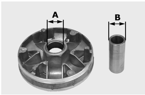
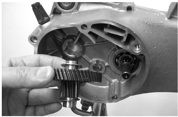
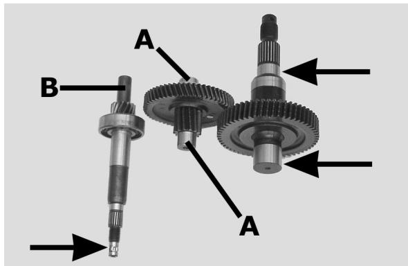
Inspecting the hub shaft
- Make sure the three shafts are not worn or deformed on the toothed surfaces, bearing and oil guard spans.
- If faults are discovered replace the damaged parts.
- Check the span (A) of the counter gear (wear, lines etc.)
- Check the seat of the pulley shaft: Worn surfaces (B) can indicate irregularity in the seats on the chassis or in the pulley shaft span
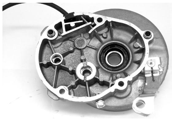
Inspecting the hub cover
- Make sure the coupling surface is not dented or deformed.
- If faults are discovered replace the hub cover.
Refitting the driven pulley shaft bearing
- Slightly heat the hub cover and then fit the bearing with the specific drift.
- Fit the circlip with the concave or radial part facing the bearing.
N.B.
FIT THE BALL BEARING WITH THE SHIELD FACING THE OIL SEAL.
Specific tooling
020151Y Air heater "METABO HG 1500/2"
020376Y Handle for punches
020439Y 17 mm guide
020358y 37 x40 adaptor
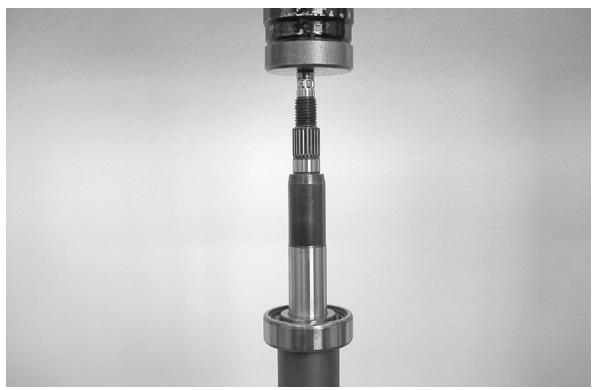
- Using the specific tool under the press, support the inner race of the bearing on the outside of the hub cover. Fit the driven pulley shaft.
- Fit the oil seal so it is flush with the cover.
Specific tooling
020452y Driven pulley shaft fitting/removing tube
Refitting the wheel axle bearing
- Place the hub cover on a wooden surface
- Heat the hub cover using the heat gun
- Preassemble the bearing on the specific punch using the grease then insert the bearing in its seat.
- Refit the seeger ring and the oil guard using the 42 × 47 adaptor
N.B.
POSITION THE OIL GUARD WITH THE SEAL RIM FACING THE INSIDE OF THE HUB.
Specific tooling
020150Y Support for air heater "METABO HG 1500/2"
020151Y Air heater "METABO HG 1500/2"
020376Y Handle for punches
020363Y 20mm guide
020359Y 42 x 47 mm hub bearing fitting adaptor
Refitting the hub bearings
- Reassemble the wheel on the cover being careful not to damage the rim of the oil guard seal
- Put a layer of grease on the two intermediate gear shear rings and fit one on the cover so that it does not interfere with the wheel axle gear when inserting the countershaft
Refitting the ub cover
- Apply a product recommended for surfaces to the hub cover and refit it on the chassis
- Install the 5 screws and tighten to the prescribed torque.
N.B.
BEFORE FITTING A NEW GASKET, REMOVE ANY RESIDUES OF THE OLD GASKET FROM THE MATING SURFACES OF THE HUB COVER AND THE CRANKCASE HALF.
Recommended products
Loctite 510 Packing fluid
Packing
Locking torques (N^*m)
Tightening torque 24 - 26
Flywheel cover
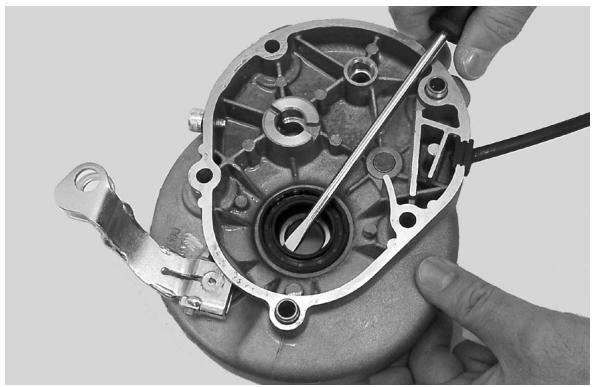
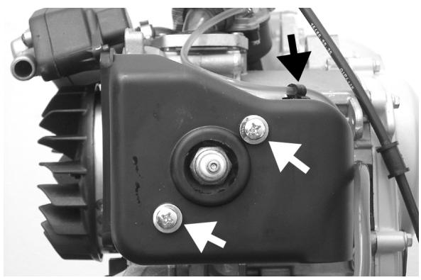
Cooling hood
- Remove the 4 fixings shown in the figure
- Remove the fan cover
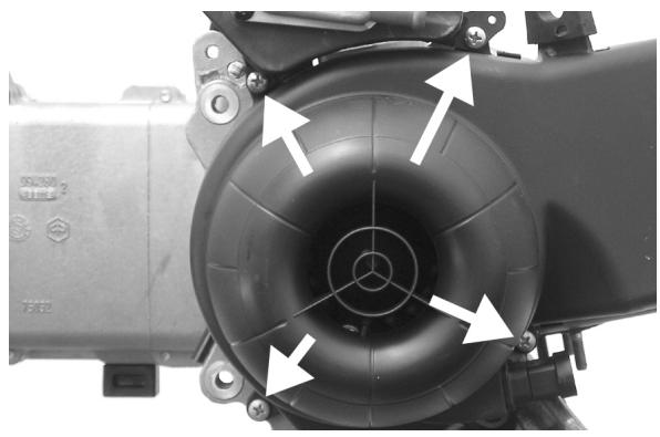
- Remove the oil line retaining zip tie from the cooling hood
- Remove the two screws shown in the picture
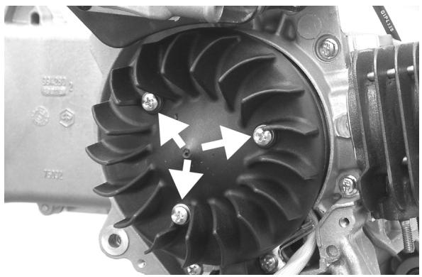
Cooling fan
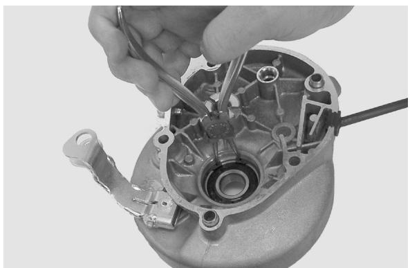
- Remove the three fastenings shown in the figure.
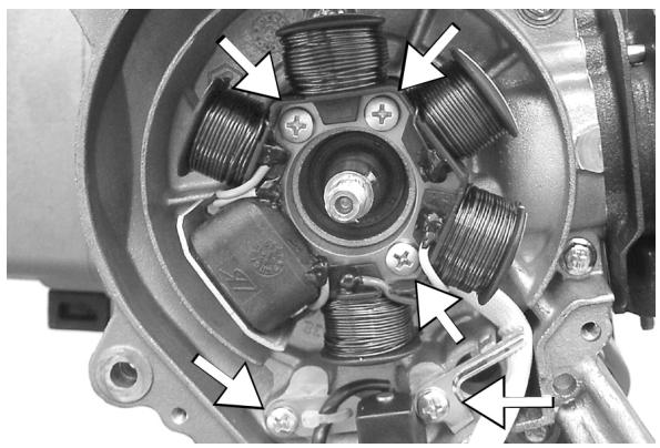
Removing the stator
- Remove the stator 3 implantations indicated in photo
- Remove the pick-up 2 implantations indicates in photo
- Remove the stator complete with wiring
Refitting the stator
- Fit the stator and the flywheel by following the reverse procedure to the removal. Tighten the fastenings with the prescribed torque.
N.B.
THE PICK-UP WIRE MUST BE POSITIONED SO THAT IT TOUCHES THE CAST TAB ON THE CRANKCASE. THIS WILL PREVENT IT FROM BEING CRUSHED BY THE FAN COVER ASSEMBLY.
Locking torques (N^*m)
Pick-up screws 3 ÷ 4 Stator screws 3 ÷ 4
Flywheel and starting
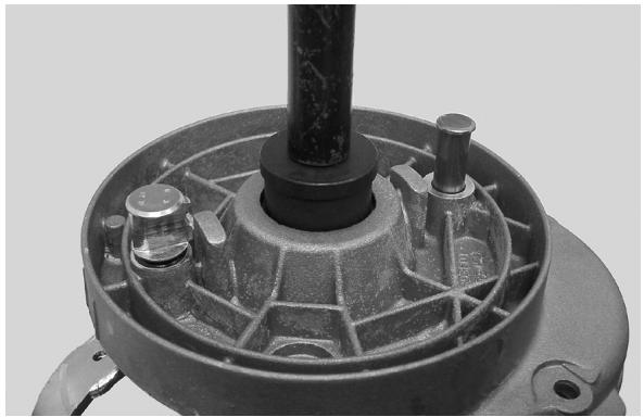
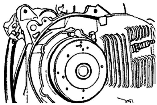
Removing the starter motor
Remove the fixings shown in the picture

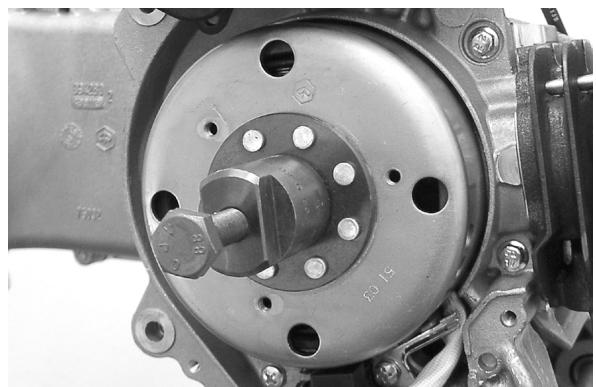
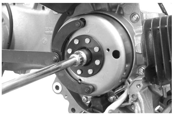
Removing the flywheel magneto
- Lock the flywheel using the compass spanner.
- Remove the nut.
CAUTION
USING A COMPASS SPANNER OTHER THAN THE ONE PROVIDED CAN DAMAGE THE STATOR COILS.
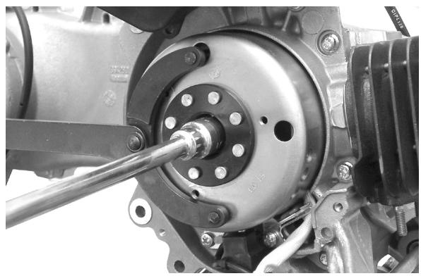
- Extract the flywheel with the specially designed extractor.
020565Y Compass flywheel stop spanner
020162y Flywheel extractor
Inspecting the flywheel components
- Check the flywheel for any distortion that might cause rubbing on the stator and the pick-up.
Refitting the flywheel magneto
- Fit the flywheel taking care to properly insert the key.
- Tighten the flywheel locknut with the prescribed torque.
- Check that the pick-up air gap is 0.5 - 0.6 ~mm No adjustment of the air gap is necessary when fitting the pick-up.
A different air gap denotes distortion of the pickup support.
N.B.
A CHANGE IN THE AIR GAP MAY ALTER THE SPARK ADVANCE AND CAUSE KNOCKING, ETC.
Locking torques (N^*m)
Flywheel nut 40 ÷ 44 N.m
Refitting the starter motor
- Fit a new O-ring on the starter motor and lubricate it.
- Install the starter motor on the crankcase and tighten the two screws with the prescribed torque.
N.B.
FIT THE REMAINING PARTS AS DESCRIBED IN THE CHAPTERS CYLINDER, CYLINDER HEAD, VALVE GEAR, LUBRICATION, FLYWHEEL AND TRANSMISSION.
Locking torques (N^*m)
Starter motor screws 11 ÷ 13
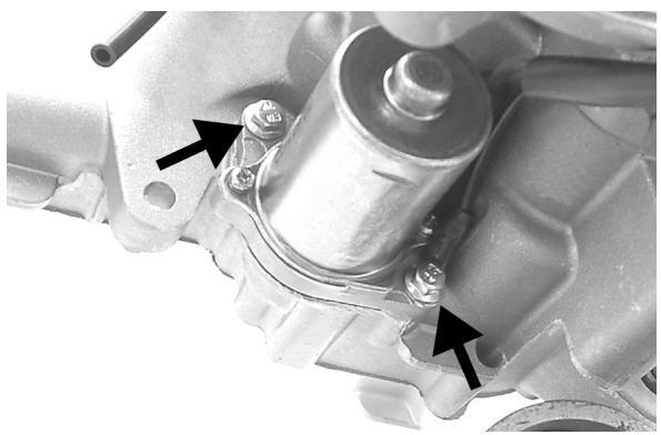
Cylinder assay. and timing system
Removing the intake manifold
Using the TORX spanner, remove the 2 intake
manifold fixing screws
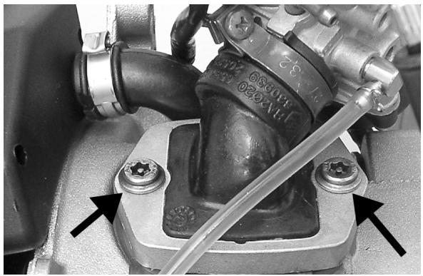
Removing the cylinder head
Remove the four nuts shown in the picture
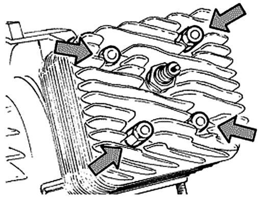
Removing the cylinder - piston assay.
Carefully remove the cylinder
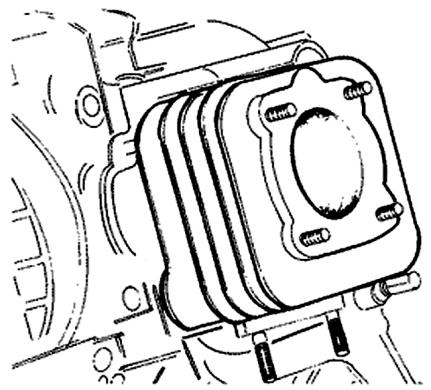
Remove the split rings and the wrist pin
CAUTION
ALWAYS REPLACE THE WRIST PIN SPLIT RINGS WITH NEW ONES
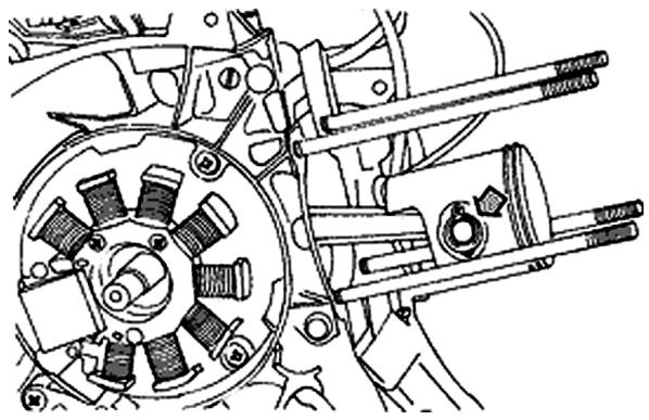
Inspecting the small end
- Using an inside micrometer, measure the small end diameter
N.B.
IF THE SMALL END DIAMETER EXCEEDS THE MAXIMUM ALLOWABLE VALUE, OR IF IT SHOWS SIGNS OF WEAR OR OVERHEATING, PROCEED TO REPLACE THE CRANKSHAFT AS DESCRIBED IN THE CHAPTER "CRANKCASE AND CRANKSHAFT".
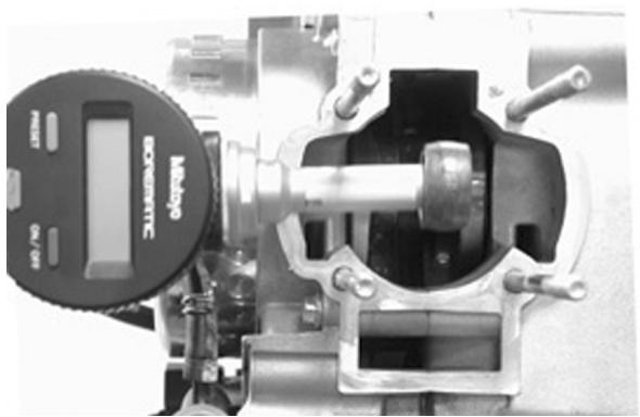
Characteristic
Standard diameter
17 +0,011-0,001
Max. allowable diameter
17,060
Inspecting the wrist pin
- Check the wrist pin external diameter using a micrometer
Characteristic
Wrist pin: standard diameter
12 +0,005 +0,001 mm
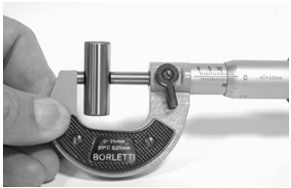
Inspecting the piston
- Using a suitable instrument measure the piston diameter
- Evaluate the piston-wrist pin fitting clearance
Characteristic
Wrist pin housing: standard diameter
12 +0,007 +0,012
Wrist pin housing: standard tolerance
0,002÷ 0,011mm
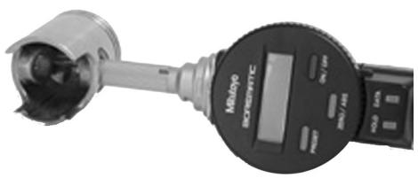
- Measure the external diameter of the piston according to a direction orthogonal to the pin axis
- Carry out the measurement at the location shown in the figure
To classify the cylinder-piston mating, check the appropriate table
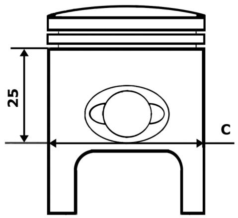
See also
Cylinder - piston assay.
Inspecting the cylinder
- Check the cylinder does not show signs of seizures. If it does proceed by replacing it or performing a grinding operation befitting the available oversize pistons
- Using an appropriate device, measure the internal cylinder diameter in the directions shown in the figure
- Check the mating surface with the head is free from wear or deformations To classify the cylinder-piston mating, check the appropriate table
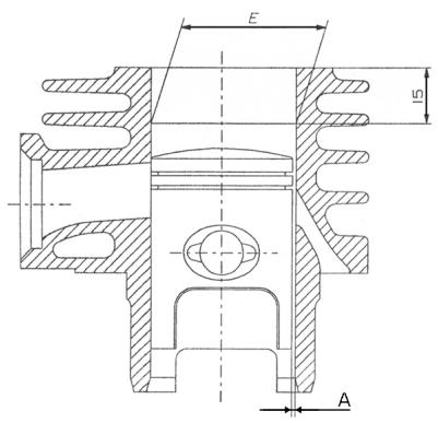
See also
Cylinder - piston assay.
Inspecting the piston rings
- Alternatively insert the two piston rings inside the cylinder
- Insert the piston rings in the direction orthogonal to the cylinder axis, using the piston to push them through.
- Measure the rings gap using a feeler gauge as shown in the picture.
- If the measured values exceed those shown in the table, proceed by replacing the rings.
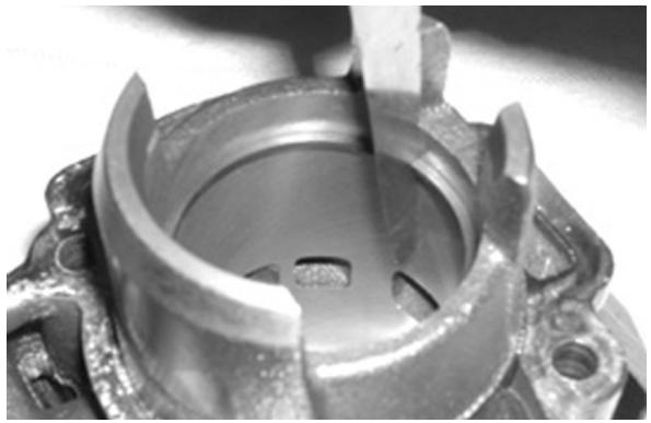
Removing the piston
- Position the piston ring inside part 1 with its opening coinciding with the arrow shown on the tool.
- Push part 2 through part 1 as far as it will go and hence extract part 2.
- Insert part 3 inside part 1, position the assembly in the piston ring housing and push part 3 home.
N.B.
REFIT THE REMAINING COMPONENTS FOLLOWING THE OPERATIONS FOR THEIR REMOVAL IN THE REVERSE ORDER.
020166y Piston rings fixing tool
Locking torques (N^*m)
Cylinder head lock nuts 10 ÷ 11 N·m
- Use new split rings for the wrist pin.
- Replace the cylinder base gasket with a new one.
- Before proceeding with the reassembly carefully clean all surfaces.
- Lubricate components with two-stroke oil when refitting piston and cylinder.
CAUTION
POSITION THE ARROW STAMPED ON THE TOP OF THE PISTON TOWARDS THE EXHAUST PORT. THE WRIST PIN SPLIT RINGS MUST BE POSITIONED ON THE PISTON USING THE SPECIAL TOOL.
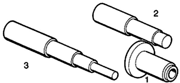
Recommended products
Selenia Hi Scooter 2 Tech Oil
Recommended oil
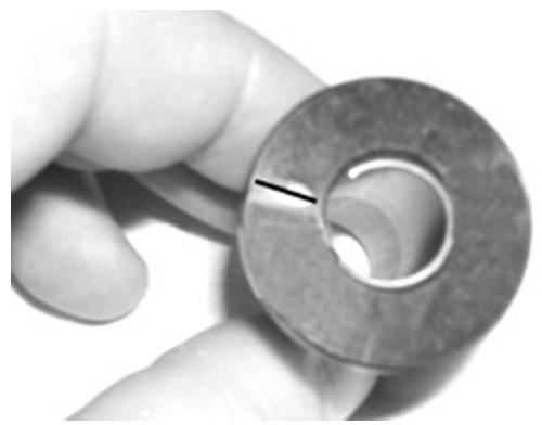
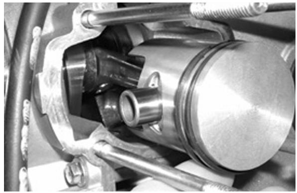
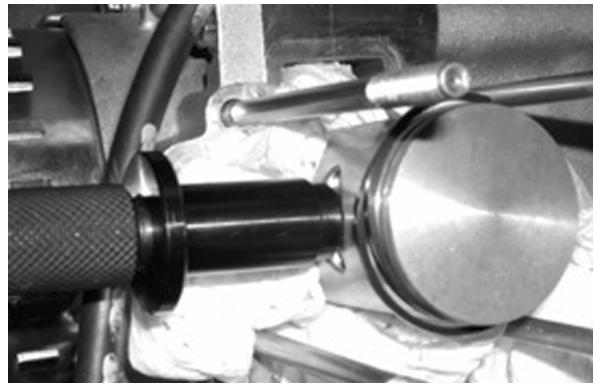
Inspecting the timing system components
CAUTION
CHECK THE LEAK TIGHTNESS OF THE REED VALVE ASSY.; NO LIGHT BE VISIBLE BETWEEN VALVE AND HOUSING.
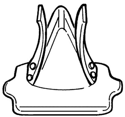
Crankcase - crankshaft
Splitting the crankcase halves
Remove the eight crankcase fasteners.
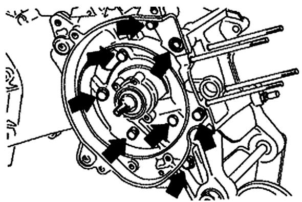
Install the special plate on the flywheel-side halfcrankcase and proceed by splitting the two halves.
Specific tooling
020163y Crankcase splitting plate
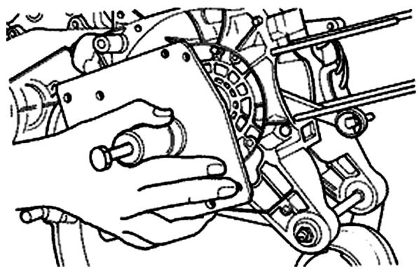
Removing the crankshaft
- Install the special tool onto the transmission-side half-crankcase using four M6 screws of adequate length.
- Remove the crankshaft from the transmission-side half-crankcase.
Specific tooling
020163y Crankcase splitting plate
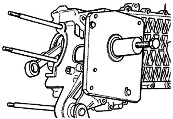
Removing the crankshaft bearings
The bearings may remain attached either to half-crankcase or crankshaft, indifferently.
- Using the special tool provided, remove only the bearings attached to the engine.
N.B.
THE HALF RINGS MUST BE FITTED ONTO THE BEARINGS WITH THE AID OF A Mallet.
Specific tooling
004499y001 Bearing extractor fitted with parts
004499y006 Bearing extractor fitted with parts
004499y002 Bearing extractor fitted with parts
004499y007 Half rings
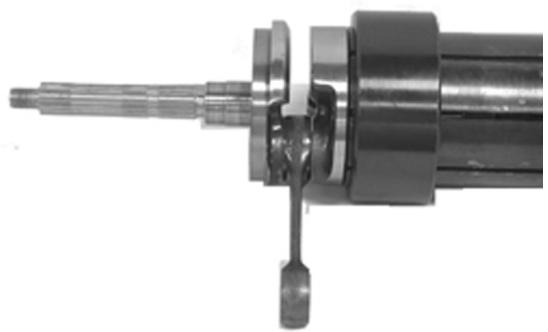
Using the special tool, remove any bearing which remained on the crankcase.
Specific tooling
001467Y007 Bell for bearings external Ø 54 mm
001467Y006 20-mm pliers
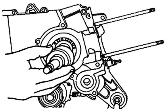
Refitting the crankshaft bearings
Heat the bearings in oil at approx. 100^ and fit them onto the crankshaft with the aid, if necessary of tube section acting directly on the internal ring of the bearing.
Specific tooling
020265y Bearing fitting stand
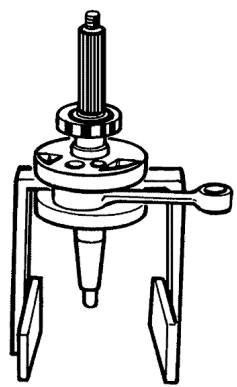
Inspecting the crankshaft alignment
Using the appropriate specific tools, check the eccentricities of the surfaces of diameters
A - B - C are within 0.03 mm (top reading limit for the dial gauge clock); check also the eccentricity of diameter D , for which a maximum
misalignment of 0.02 ~mm is allowed. In the event that the eccentricities are not too far off the prescribed values, straighten the crankshaft by acting with a wedge in between the counterweights or by using vice (with aluminium mouth guards) according to your needs.
020335Y Magnetic stand and comparator
020074Y Crankshaft aligning tool
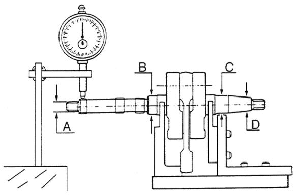
Refitting the crankshaft
- Rest the transmission-side half-crankcase on two wooden supports.
- Using a heat gun, heat the bearing housing up to approx. 120^ .
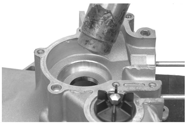
- Insert the crankshaft and push it in as far as the bearing will go.
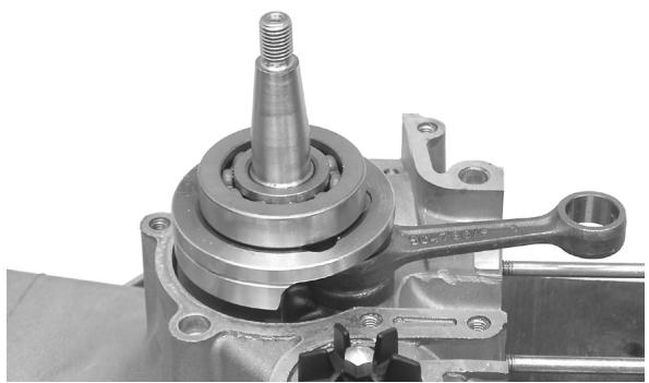
020163y Crankcase splitting plate
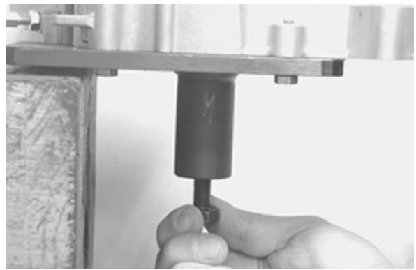
Refitting the crankcase halves
- Prepare the mating plane by applying a thin layer of LOCTITE 510, after cleaning the surface with and adequate solvent (e.g. acetylene trichloride).
- Heat the flywheel-side half-crankcase using a heat gun.
Recommended products
Loctite 510 Packing fluid
Packing
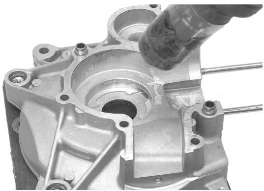
- Keeping the transmission-side half-crankcase in horizontal position, vigorously and accurately insert the flywheel-side half-crankcase.
- Insert at least 3 fixing screws and tighten them quickly.
- Insert the other 5 screws and tighten them at the prescribed torque.
Locking torques (N^*m)
Crankcase fixing screws 11 - 13
- Move the crankcase splitting plate backwards as shown in the figure.
- Install the special magnetic mounting with its dial gauge, at the end of the crankshaft.
- Check the crankshaft axial play.
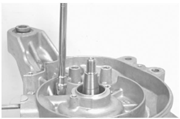
- If the measurements do not match those prescribed, repeat the crankshaft reassembly operation.
020335Y Magnetic stand and comparator
Characteristic
Axial play with warm crankcase
0,10÷ 0,12mm
Axial play with cold crankcase
0,06÷ 0,08mm
Limit value with cold crankcase
0,02÷ 0,03mm
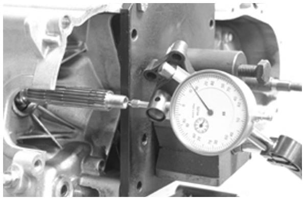
Lubrication
Crankshaft oil seals
Refitting
- Install a new flywheel-side oil seal using the puncher from the special tool.
The flywheel-side oil seal may be recognised for having a smaller diameter.
N.B.
THE SPECIAL TOOL MAY NOT BE USED WHEN THE WOODRUFF KEY IS FITTED
020340Y Punch for fitting oil guard magneto and transmission
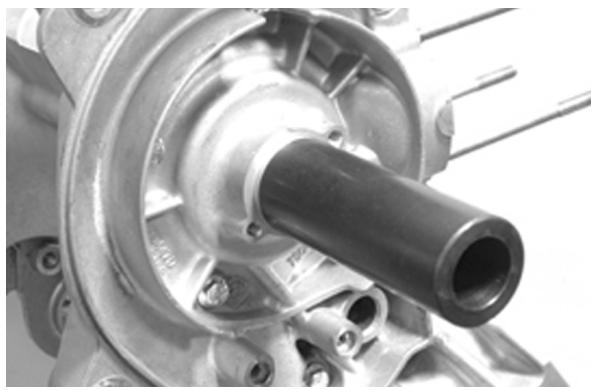
- Install a new transmission-side oil seal using the special tool fitted with adapter ring.
The transmission-side oil seal may be recognised by its larger diameter.
020340Y Punch for fitting oil guard magneto and transmission
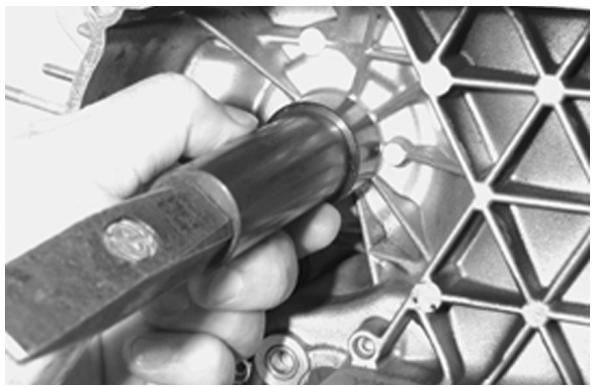
Oil pump
Removal
Remove the two screws shown in the figure
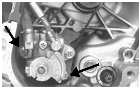
Remove the fairlead from the crankcase, as indicated in the figure.
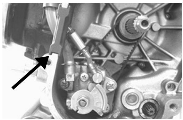
Refitting
For the reassembly follow the removal operations in the reverse order.
After the reassembly, it is recommended to bleed the system by acting upon the screw shown in the picture.
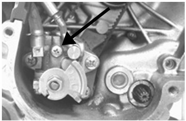
Fuel supply
- Disconnect the fuel feed pipe and the vacuum pipe from the carburettor.
- Ensure that no fuel is leaking from the pipes.
- Close the fuel outlet.
- Using the MITYVAC pump, apply a 0.1 bar vacuum to the cock.
- Ensure that the vacuum does not change, and that no fuel is leaking.
- Reconnect the vacuum pipe to the manifold.
- Position the fuel pipe so that its outlet is on the same level as the cock.
- Make the engine turn by operating the starter motor for five seconds with the carburettor in the idle position.
- Gather the fuel in a graduated burette.
N.B.
THE MEASUREMENT MAY BE ALTERED BY AN UNSUITABLE ENGINE SPEED OR BY INCORRECT POSITIONING OF THE PIPE. IN THAT CASE, A REDUCED FUEL DELIVERY IS GENEALLY OB-TAINED. THE VACUUM HOLE ON THE MANIFOLD HAS AN INTENTIONALLY REDUCED CROSS-SECTIONAL AREA IN ORDER TO IMPROVE THE VACUUM PULSES AND ENSURE CONSTANT DELIVERY OF THE COCK.
Specific tooling
020329Y Pump MITYVAC
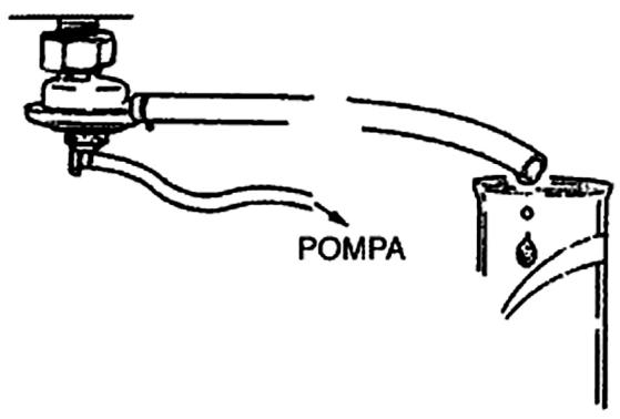
Characteristic
Minimum delivery
20 cc
- Drain the fuel from the tank.
- Remove the fuel delivery pipe and the vacuum pipe.
- Release the clamp and remove the cock.
- Clean the tank and the cock filter with a suitable solvent.
- Refit the cock taking care to verify the presence of the O-ring.
- Turn the cock in the same direction as before the removal and then tighten the clamp.
N.B.
THE FILTER CAN BE SCREWED OFF THE COCK TO FACILITATE THE CLEANING.
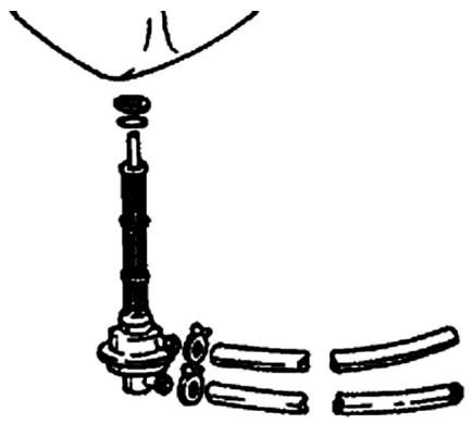
INDEX OF TOPICS
SUSPENSIONS
SOSP
Front suspension
This section describes the operations which can be carried out on the suspensions.
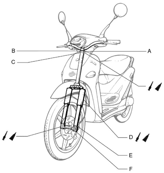
Front
Front wheel hub overhaul
Ball bearings to hub
- Fit the spacer
- Fit the ball bearings and bushes and position the seal rings.
WARNING
PRIOR TO REASSEMBLY, LUBRICATE WITH JOTA 3 F.S. GREASE IN THE AREAS MARKED WITH THE ASTERISK.
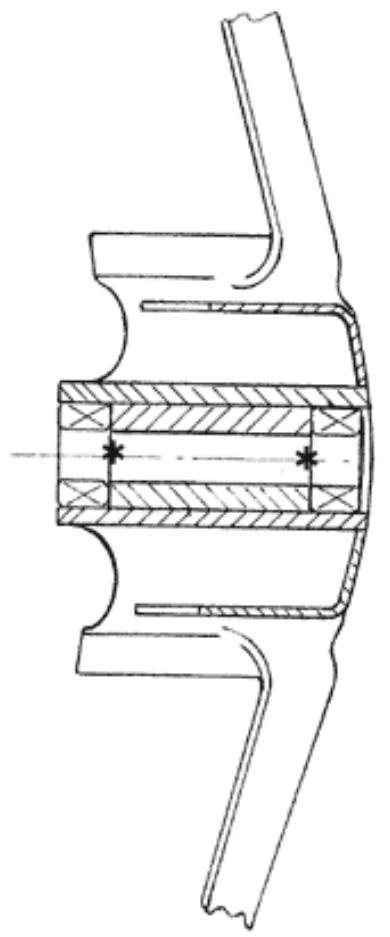
Handlebar
Removal
Disassembling the handlebar
- Before proceeding, remove the handlebar fairing.
- After detaching flexible transmission cables and disconnecting electrical terminals, loosen the clamp securing the handlebar to the steering tube
- Check all components and replace any damaged or defective parts.
N.B.
IF YOU ARE REMOVIDING THE HANDLEBAR ONLY SO THAT YOU CAN THEN REMOVE THE STEERING ASSEMBLY, SIMPLY ALLOW THE HANDLEBAR TO
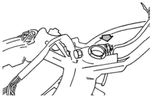
TIP OVER THE FRONT OF THE SCOOTER, TAKING CARE THAT FLEXIBLE TRANSMISSION CABLES ARE NOT DAMAGED.
Front fork
Overhaul
O-ring renewal and rod disassembly
- Disassemble the wheel spindle.
- Remove lower screw (1).
- Allow the fork oil to drain out.
- Withdraw the rod.
- Renew the O-rings (3 - 4).
- Insert the rod and refit lower screw (1).
- Remove upper screw (2).
- Pour in 30 cc ± 1 of "FORK PG" (SAE 20W fork oil)
- Reassemble all parts.
Locking torques (N^*m)
Lower screw tightening torque: 20 ÷ 25 N·m
Upper screw tightening torque: 20 ÷ 25 N·m
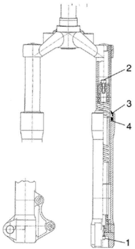
Steering column
Refitting
Lower and upper bearing races to frame
Lower and upper bearing races to frame
LOWER AND UPPER BEARING RACES TO FRAME
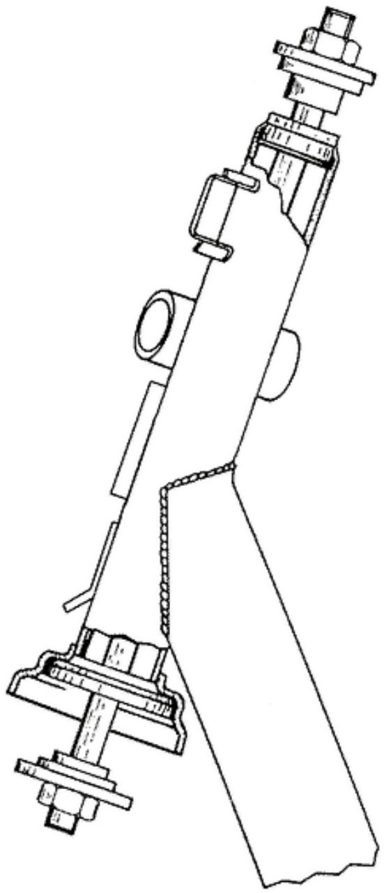
Steering bearing
Steering collar
Steering collar
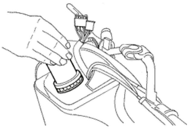
Steering bearing upper race
- Lubricate race and balls with Z2 grease.
- Tighten to the specified torque and then rotate the tool through 80^ - 90^ in an anticlockwise direction.
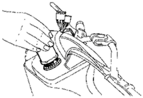
Removal
Lower and upper races from frame
- To remove the bearing races from the frame use the relative special tool as shown in the figure.
N.B.
THE LOWER BEARING RACE CAN BE PRISED OFF BY LEVERING IT WITH A SCREWDRIVER OR SIMILAR.
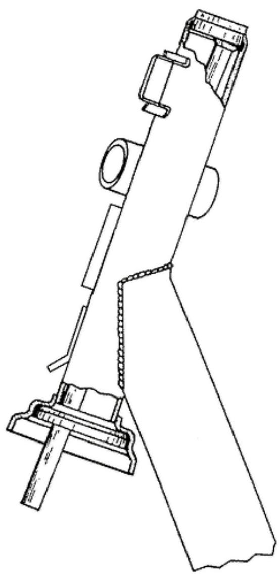
LOWER AND UPPER RACES FROM FRAME
Upper bearing washer and race
- Remove the upper race and then lean the vehicle over to one side in order to remove the steering tube, after having removed the spray guard and brake calliper.
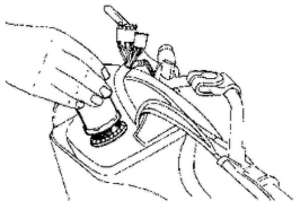
Rear
Removing the rear wheel
- Prise off the hub cap by levering against the brake drum with a screwdriver
- Straighten the split pin and remove the cap.
- Unscrew the wheel spindle nut and remove the wheel.
- On reassembly, tighten the spindle nut to the prescribed torque.
WARNING
USE A NEW SPLIT PIN.
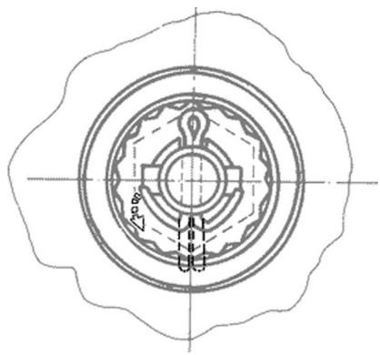
Refitting the rear wheel
- Refit the parts as directed for disassembly but in the reverse order, tighten the wheel nut to the prescribed torque.
WARNING
BEND OVER THE SPLIT PIN ENDS AS SHOWN IN ORDER TO ELIMINATE PLAY BETWEEN THE CAP AND WHEEL SPINDLE.
Locking torques (N^*m)
Rear wheel axle 104 ÷ 126
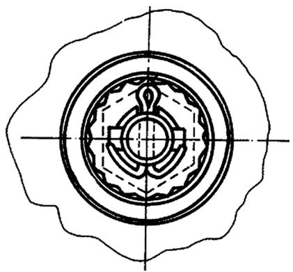
Shock absorbers
Removal
Absorber
- To replace the shock absorber, remove the rear cover and the battery access door. This action exposes the shock absorber/frame fixing nut, which must now be removed. Subsequently, remove the shock absorber-engine pivot pin.
- At the time of reassembly, tighten the shock ab
sorber-frame fixing nut and the shock absorber/engine pivot pin to the prescribed torques.
Locking torques (N^*m)
Shock absorber/engine pivot pin 33 ÷ 41 N·m
Shock absorber/frame nut 20 ÷ 25 N·m
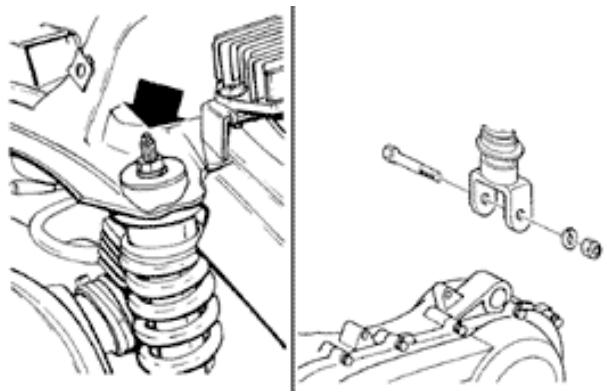
Centre-stand
Expelling stand pivot pin from bracket
- Disassemble the stand bracket from the engine.
- Drill to a depth of 5 mm from one side in order to remove pivot pin «P».
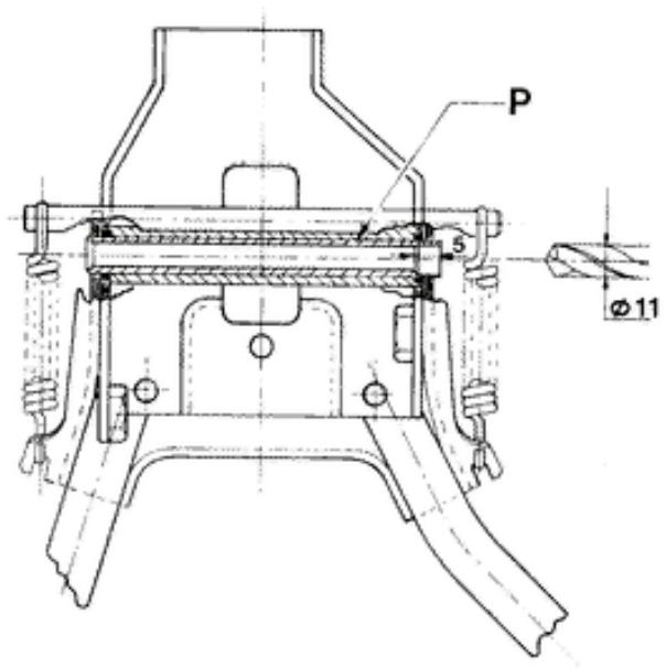
Assembly and staking of stand pivot pin to bracket
- Stake the end of pin «P» using the two punches shown in the figure.
- The stand should turn freely on its pivot after this operation.
N.B.
REASSEMBLE THE STAND USING NEW O-RINGS AND A NEW PIN. GREASE THE SPRING ATTACHMENT POINTS AND THE PIN.
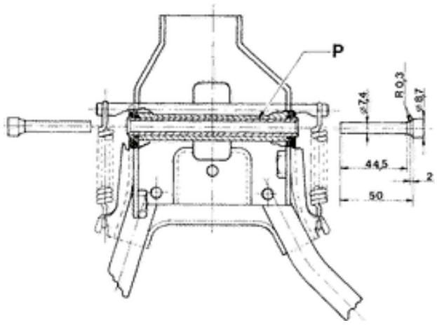
Changing the complete stand
- Remove the 2 screws shown in the figure.
- On reassembly, tighten to the prescribed torque.
Locking torques (N^*m)
Stand bracket screws 18,5 ÷ 19 N·m
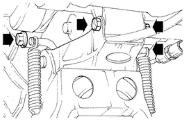
INDEX OF TOPICS
BRAKING SYSTEM
IMP FRE
After removing the muffler and wheel proceed as follows:
1.Remove the shoe spring using the specific pliers.
2.Remove the shoes using a lever.
3.Fit the new shoes using a mallet and hitting lightly.
4.Hook the spring using the specific pliers.
020325y Pliers for brake-shoe springs
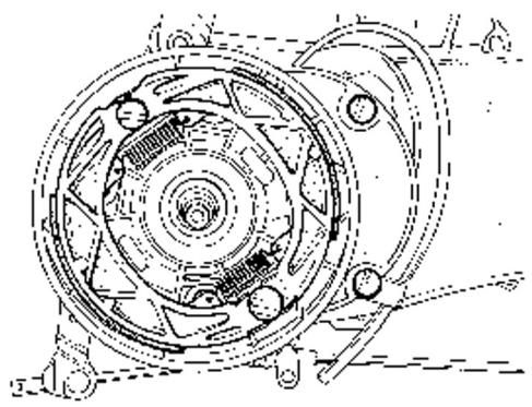
Rear brake calliper
Refitting
Insert the following parts into the calliper half bodies:
- sealing rings (1-2);
- pistons (3);
- fit O-ring seal (4) in one of the pump bodies.
- Couple the inner and outer bodies by means of the coupling bolts. Fit the pads and bleed air from the system (see previous paragraphs).
- Position the caliper on the disc and fasten it to the support, tightening the bolts.
- Secure the tube connection to the caliper with the required torque.
- Before reassembly, the parts must be perfectly clean and bear no traces of oil, diesel fuel, grease, etc.. They must therefore be washed thoroughly in denatured alcohol before proceeding.
Immerse the seals in brake fluid; the use of protective agent PRF1 is tolerated.
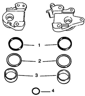
CAUTION
RUBBER PARTS MUST NOT BE LEFT IN ALCOHOL FOR MORE THAN 20 SECONDS. AFTER WASHING, DRY THE PARTS WITH COMPRESSED AIR AND A CLEAN CLOTH
Locking torques (N^*m)
Screw fixing the caliper to the support 20 ÷ 25 Calliper to tube connection 8 ÷ 12 Nm
Front brake calliper
Removal
- Disconnect the brake tube and allow the fluid to flow into a container.
- Remove the screws shown in the figure.
- When reassembling, tighten the nuts to the prescribed torque.
- Bleed air from the brake circuit.
Locking torques (N^*m)
Fixing screw 20 ÷ 25 Nm Brake tube union 20 ÷ 22 Nm
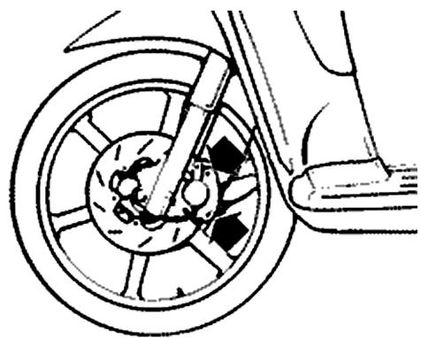
Overhaul
- Remove the calliper assembly bolts and take out the internal parts from both bodies. If necessary, use short blasts of compressed air through the brake fluid passage to facilitate expulsion of the pistons.
- Make sure the cylinders of the calliper inner and outer bodies are not scratched or eroded. If they are, renew the entire calliper.
CAUTION
ALL INTERNAL COMPONENTS MUST BE RENEWED AT EACH CALLIPER OVERHAUL.
Refitting
Insert the following parts into the calliper half bodies:
- sealing rings (1-2);
- pistons (3);
- fit O-ring seal (4) in one of the pump bodies.
- Couple the inner and outer bodies by means of the coupling bolts. Fit the pads and bleed air from the system (see previous paragraphs).
- Position the caliper on the disc and fasten it to the support, tightening the bolts.
- Secure the tube connection to the caliper with the required torque.
- Before reassembly, the parts must be perfectly clean and bear no traces of oil, diesel fuel, grease, etc.. They must therefore be washed thoroughly in denatured alcohol before proceeding.
Immerse the seals in brake fluid; the use of protective agent PRF1 is tolerated.
CAUTION
RUBBER PARTS MUST NOT BE LEFT IN ALCOHOL FOR MORE THAN 20 SECONDS. AFTER WASHING, DRY THE PARTS WITH COMPRESSED AIR AND A CLEAN CLOTH
Locking torques (N^*m)
Screw fixing the caliper to the support 20 ÷ 25 Calliper to tube connection 8 ÷ 12 Nm
1 DUST SEALS
2 OIL SEALS
3 PISTONS
4 O-RING
Front brake disc
Removal
- Remove the wheel by removing the spindle fixings.
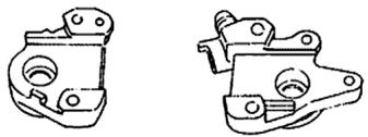
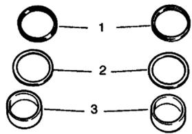
O-4
- Unscrew the 6 disc fixing screws.
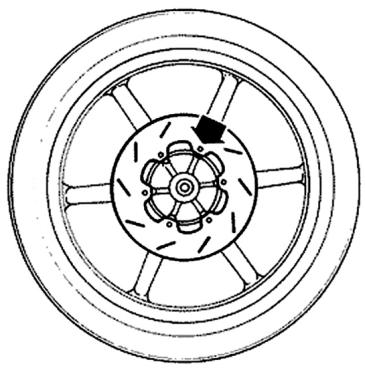
Refitting
- When reassembling, ensure the disc is positioned correctly in relation to the direction of rotation.
Locking torques (N^*m)
Disc screws: 8 ÷ 12
Disc Inspection
- Remove the wheel and check disc flatness.
Maximum permissible out of true is 0.1 mm. If the value measured is greater, fit a new disc and repeat the check.
- If the problem persists check and replace the wheel if necessary.
Specific tooling
020335Y Magnetic stand and comparator
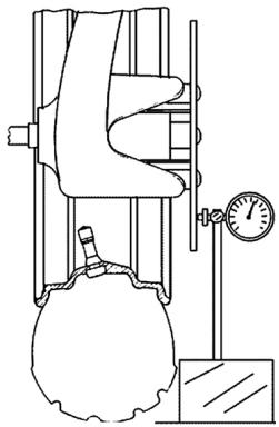
Front brake pads
Removal
-
To facilitate this operation remove the two calliper fixings. With the calliper detached from its support but still connected to the brake fluid line, remove the plastic cover by prising it with a screwdriver.
-
Remove the outside circlip from the brake pad
pin, the leaf spring and the pads.
- Renew the pads when friction facing thickness is less than 1.5 ~mm .
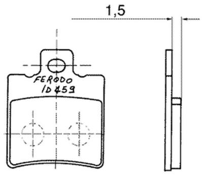
Refitting
- To reassemble perform the above steps in reverse order. Position the leaf spring with the arrow facing up.
Fill
Front
-With the bleed valve closed, fill the system to the maximum level with brake fluid.
- Loosen the bleed valve.
- Apply the Mityvac vacuum pump tube to the bleed valve.
To bleed the circuit you must supply the reservoir constantly with brake fluid while pumping the
Mityvac pump until there are no more air bubbles in the circuit.
The operation is concluded when the bleed valve delivers brake fluid and no air.
When you have finished the above procedure, tighten the bleed screw to the prescribed torque.
N.B.
IF YOU FIND YOU CANNOT ELIMINATE THE AIR, EXAMINE ALL THE UNIONS IN THE CIRCUIT.
IF YOU DON'T FIND ANY LEAKS, SEEK THE FAULT IN THE VARIOUS SEALS ON THE
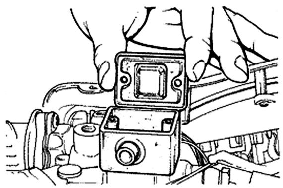
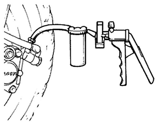
MASTER CYLINDER AND BRAKE CALLIPER PISTONS.
CAUTION
DURING THIS PROCEDURE THE VEHICLE MUST BE ON THE STAND ON A LEVEL AND HORIZONTAL FLOOR.
N.B.
DURING THE BLEED PROCEDURE, CHECK THE FLUID LEVEL IN THE MASTER CYLINDER RESERVOIR FREQUENTLY TO PREVENT THE RISK OF AIR ENTERING THE CIRCUIT THROUGH THE MASTER CYLINDER.
WARNING
BRAKE FLUID IS HYGROSCOPIC. I.E. IT TENDS TO ABSORB MOISTURE FROM THE SURROUNDING AIR.
IF THE LEVEL OF MOISTURE IN THE FLUID EXCEEDS A GIVEN VALUE, BRAKING EFFICIENCY WILL BE REDUCED.
THEREFORE, ALWAYS USE FLUID FROM SEATED CONTAINERS.
IN NORMAL RIDING AND CLIMATIC CONDITIONS THE BRAKE FLUID SHOULD BE CHANGED EVERY 2 YEARS.
IF THE BRAKES ARE USED INTENSELY AND/ OR IN HARSH CONDITIONS, CHANGE THE FLUID MORE FREQUently.
CAUTION
DURING THE ABOVE PROCEDURES BRAKE FLUID MAY LEAK FROM BETWEEN THE BLEED SCREW AND ITS SEAT ON THE CALLER.
DRY THE CALLIPER CAREFULLY AND DEGREASE THE DISC TO REMOVE ALL TRACES OF BRAKE FLUID.
Specific tooling
020329Y Pump MITYVAC
Recommended products
TUTELA TOP 4 Brake fluid
Synthetic fluid SAE J1703, NHTSA 116 DOT 4, ISO 4925
Locking torques (N^*m)
Oil drainage screw 8 ÷ 12
Front brake pump
Locking torques (N^*m)
Brake tube connection 20 ÷ 25 Nm
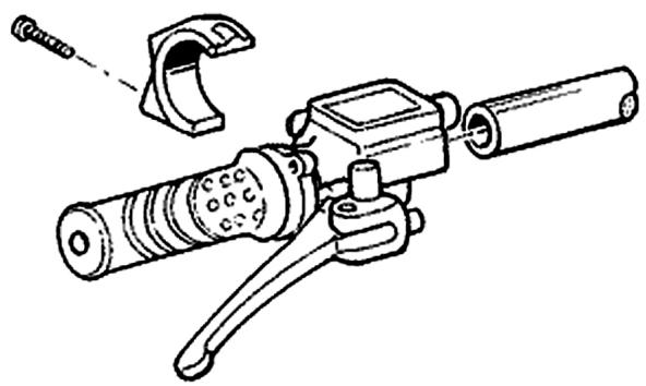
Removal
- Drain the brake fluid from the circuit through the bleeding screw on the calliper. Actuate the brake lever until the fluid stops flowing out.
- Remove the master cylinder from the handlebar, take off the brake lever and proceed to remove the brake cylinder.
1 - Reservoir cover screw
2 - Reservoir cover
3-Membrane
4-Bellows
5 - Sealing ring
6-Piston
7 - Gasket
8 - Spring
CAUTION
THE PRESENCE OF BRAKE FLUID ON THE DISC OR PADS REDUCES BRAKING ACTION. IN THIS CASE, RENEW THE PADS AND CLEAN THE DISC WITH A HIGH QUALITY SOLVENT.
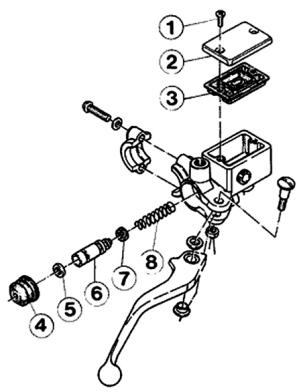
CAUTION: BRAKE FLUID CAN DAMAGE PAINTWORK.
DO NOT LEAVE RUBBER PARTS IN ALCOHOL FOR MORE THAN 20 SECONDS.
AFTER WASHING, DRY THE PARTS WITH A BLAST OF COMPRESSED AIR AND A CLEAR CLOTH.
SEALING RINGS MUST BE IMMERSED IN BRAKE FLUID.
Refitting
Before reassembly, the parts must be perfectly clean and bear no traces of oil, diesel fuel, grease, etc.. They must therefore be washed thoroughly in denatured alcohol before proceeding.
- Perform the disassembly steps in reverse order, taking care to installed rubber parts correctly to ensure an oiltight seal.
1 - Reservoir cover screw
2 - Reservoir cover
3 - Membrane
4-Bellows
5 - Sealing ring
6 - Piston
7 - Gasket
8 - Spring
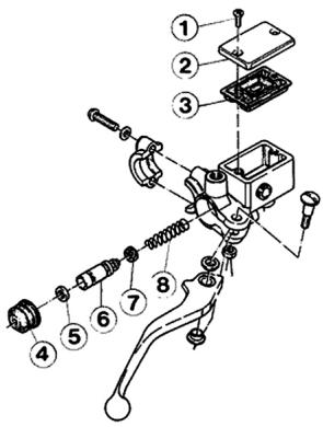
INDEX OF TOPICS
CHASSIS
CARROZ
BODYWORK
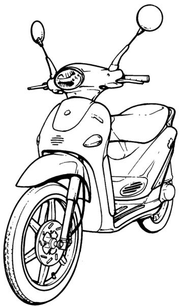
Taking apart approached cover motor
Remove the 2 implantations.

Seat
- Unscrew the 2 screws securing it and remove it
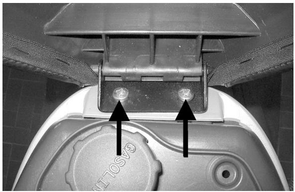
Side fairings
- Remove the countershield
- Unscrew the 4 screws securing it and remove the bumper band
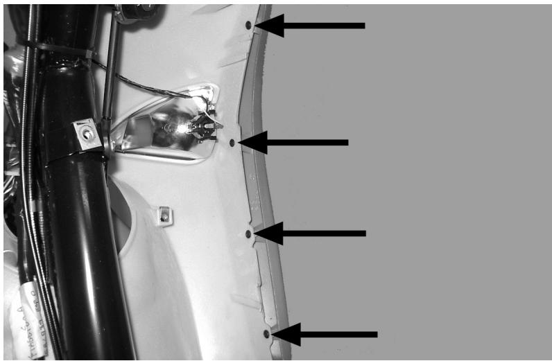
See also
Knee-guard
Rear rack
- Use a screwdriver from the back part and remove the plastic cap covering the central screw.
- Remove the central screw and the two side ones.
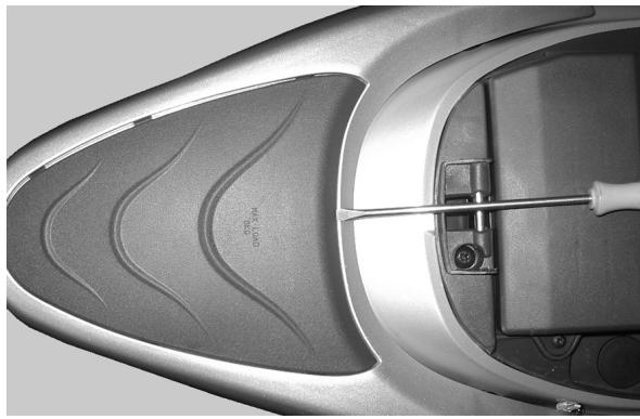
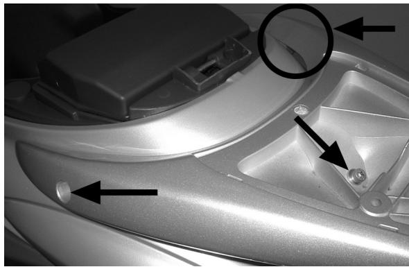
Driving mirrors
-
With the register screw completely tightened, screw the mirror stem all the way down on the handlebars.
-
Loosen the mirror and put it in the desired position.
- Loosen the register screw until the stem is tightened.
Locking torques (N^*m)
Mirror register screw 24÷26
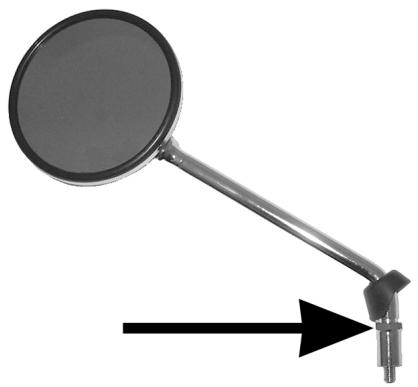
Rear handlebar cover
- Remove the front handlebar fairing
- Unscrew the speedometer transmission connection and remove it
- Disconnect the instrument unit and electrical control connections
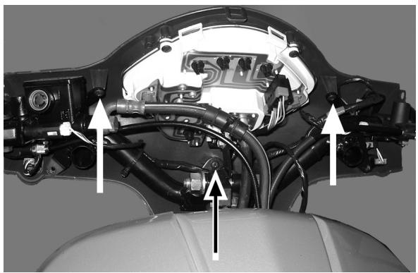
- Cut the band holding the front brake hoses to the instrument unit
- Remove the screw securing the instrument unit to the handlebar
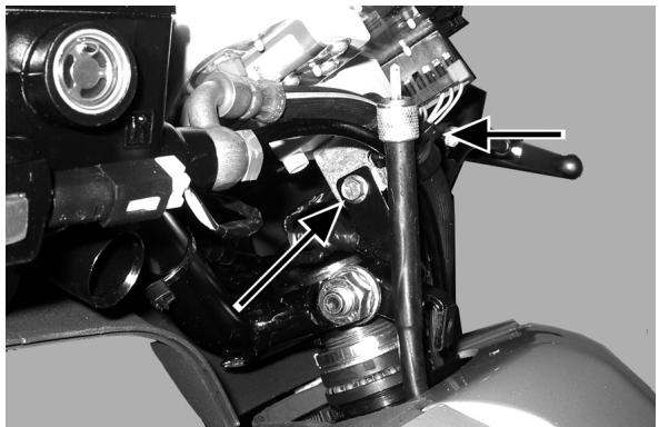
See also
Front handlebar cover
Instrument panel
- Remove the rear handlebar fairing
- Unscrew the 4 screws securing it and remove the instrument unit
N.B.
THE BULBS HAVE BAYONET COUPLING ON THE
LAMP-HOLDER; THE LAMP-HOLDER CAN BE REMOVED BY ROTATING IT 30^ ANTI-CLOCKWISE. THE CLOCK RUNS ON A BATTERY
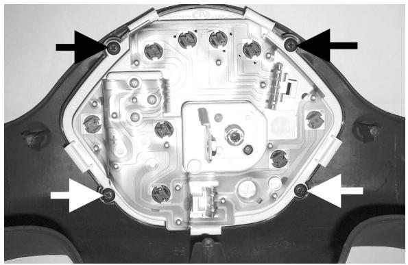
See also
Rear handlebar cover
Front handlebar cover
- Remove the 2 screws in the handlebar fairing and the screw under the headlight.
- Pull up to release the handlebar fairing and disconnect the headlight connections
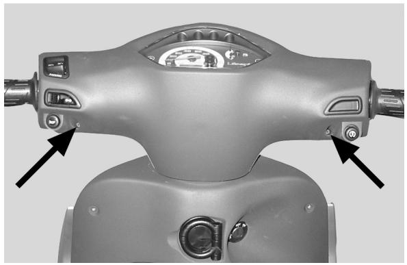
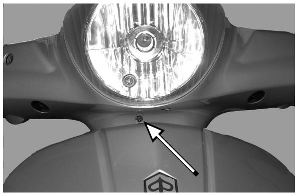
Headlight assay.
- Remove the front handlebar fairing
- Unscrew the 4 screws securing it and remove the headlight
N.B.
TO REPLACE THE HIGH BEAM/DIPPED BEAM BULB THE RUBBER COVER MUST BE REMOVED
AND THE SUPPORT PLATE ROTATED 30^ ANTI-CLOCKWISE. TO REPLACE THE POSITION LIGHT BULB, JUST REMOVE IT FORM THE RUBBER LAMP-HOLDER.
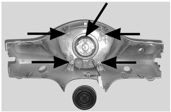
See also
Front handlebar cover
Frame central cover
- Remove the rear rack
- Remove the saddle
- Remove the sparkplug cap, then unscrew the 2 screws connecting the saddle compartment band with the footrest.
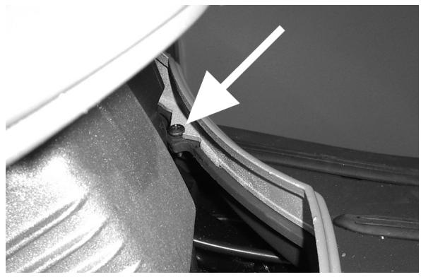
- Unscrew the two side screws on the bumper bands
- Remove the cover by lifting the rear part and disconnecting the headlight and turn signal connections
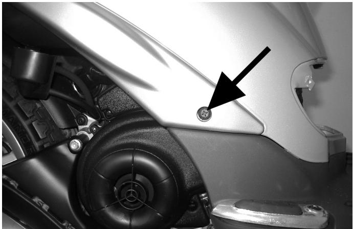
See also
Rear rack
Seat
Legshield
- Remove the countershield
- Remove the footrest
- Remove the front steering tube
- Remove the front shield using a blade and working carefully on the right side of it
- Unscrew the screw below and lift off the cover
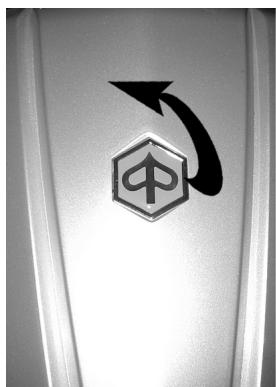
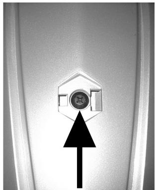
- Unscrew the front screw securing the shield
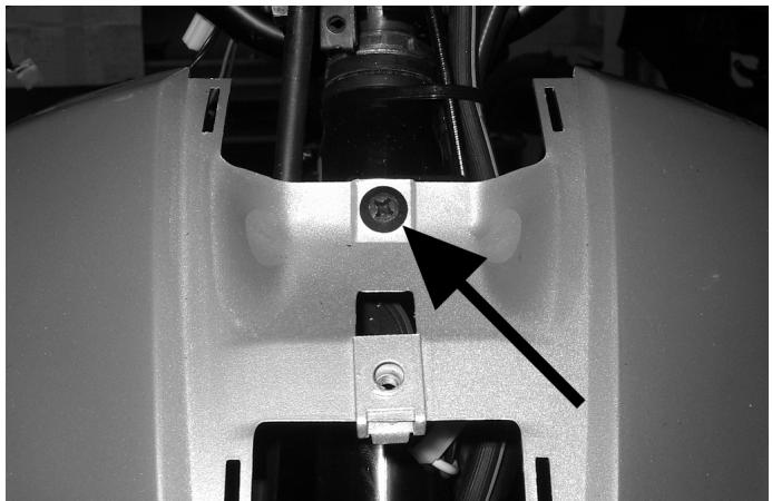
- Unscrew the lower 2 screws, then remove the shield after having disconnected the turn signal connections
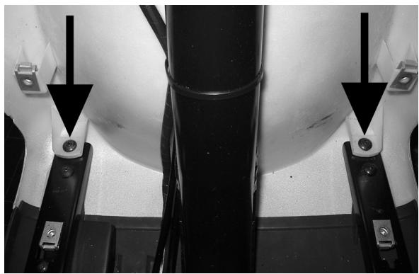
See also
Knee-guard
Footrest
Removal
Knee-guard
- Remove the 4 external screws of the coun
tershield and the 3 located inside the front glove box
- Use the bag clip to pull the countershield back until releasing it with the front shield
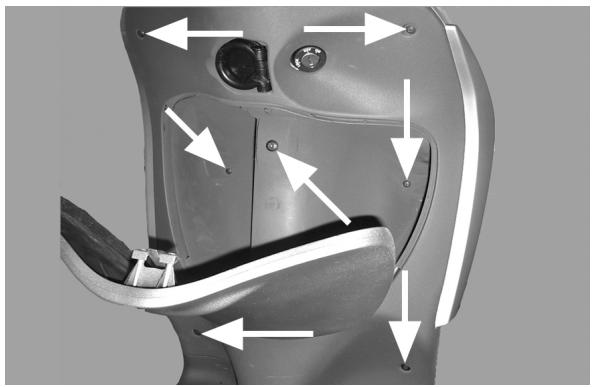
Removing the ignition key-switch when on
- Remove the countershield
- Press the lock body until the clip appears from the groove
- Keep the lock body still and use pliers to remove the clip
- Remove the lock block
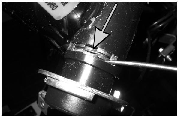
See also
Knee-guard
Removing the ignition key-switch when on
- Disassemble the shield.
- Remove the keyswitch.
- Drill into the block as shown in the figure.
- Insert the cylinder complete with key and with the locking tab facing downwards about half way into the lock body ensuring that during insertion the key is turned to the «ON» position (this is the only position that allows the cylinder to be inserted into the lock body); turn the key to the left towards the «OFF» position and simultaneously press the cylinder fully home.
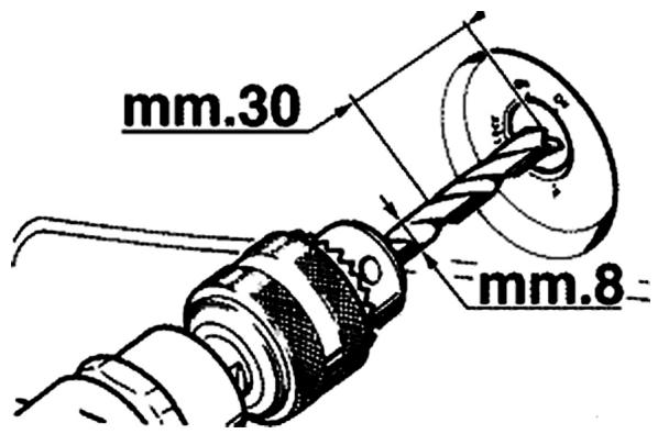

Taillight assay.
- To remove the taillight and position light or the 2 turn signals, just unscrew the screws located on the related light covers and disconnect the electrical connections.
N.B.
REMOVAL OF THE REAR LIGHT BULBS IS ONLY POSSIBLE BY REMOIVING THE LIGHT COVERS ROTATING THEM 30^ ANTI-CLOCKWISE.
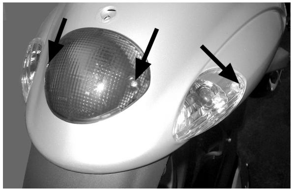
- Remove the countershield
- Remove the frame central cover
- Unscrew the screws that secure the passenger footrest and remove it
- Unscrew the footrest stop screw and remove the tab
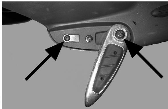
- Remove the 2 external rubber caps of the screws securing the footrest and unscrew them
- Pull the footrest up being careful of the lower hooks
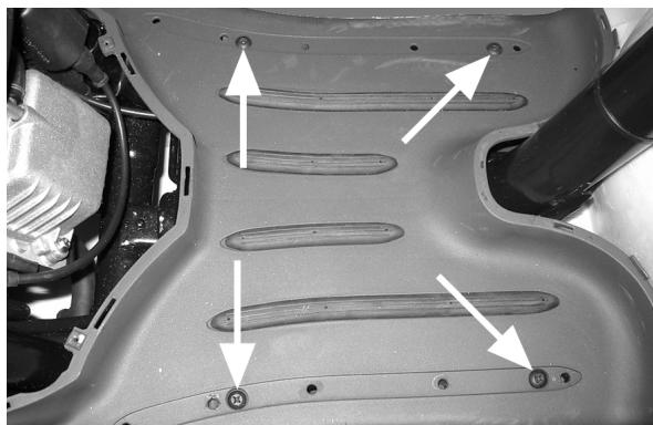
See also
Knee-guard
Frame central cover
License plate holder
- Remove the saddle compartment cover
- Unscrew the 2 screws securing it to the frame,
then remove the license plate housing
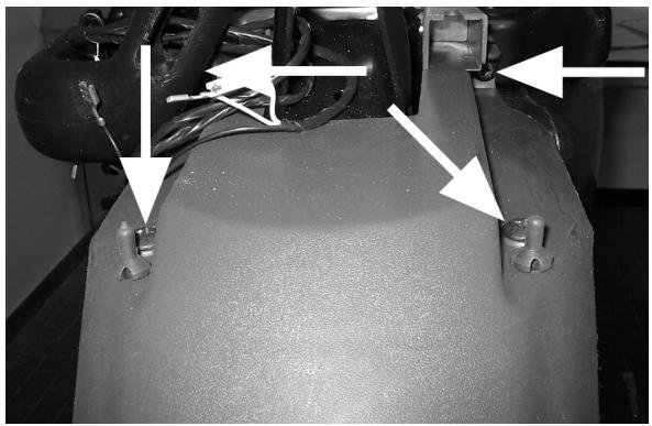
See also
Frame central cover
Air filter
- Unscrew the 7 screws located on the cover and remove it to access the filtering sponge
- To disassemble the entire filter box, unscrew the 2 lower screws and disconnect the sleeves connecting the carburetor with the external air intake.
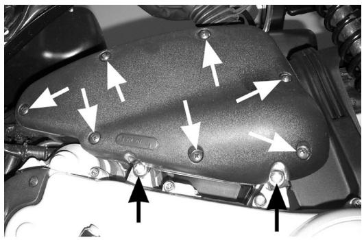
Rear mudguard
- Remove the 3 screws securing it on the left side (including the 2 screws securing the air filter box)
- Remove the screw on the side of the cooling casing
- Remove the mudguard by taking it off the muffler side.
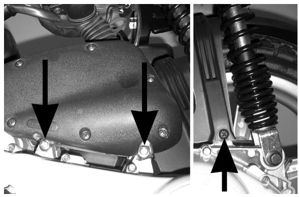
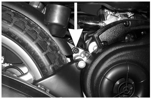
Helmet bay
- Remove the central saddle compartment cover
- Remove the battery and fuse holder
- Remove the fuel tank cap and the starter motor contactor
- Unscrew the rear screw and then lift the helmet compartment
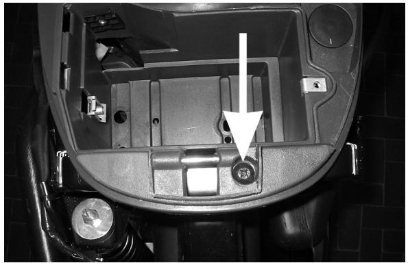
See also
Frame central cover
spoiler
- Remove the footrest
- Unscrew the two front screws securing it and then remove the spoiler from the bottom
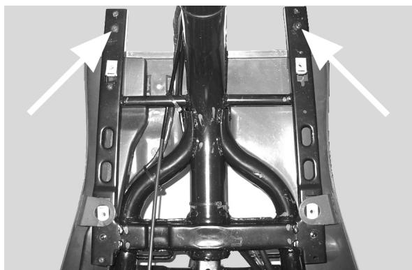
See also
Footrest
Fuel tank
- Remove the central saddle compartment cover
- Unscrew the front and rear screws on the right side of the frame
- Disconnect the vent tube and disassemble the float
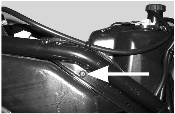
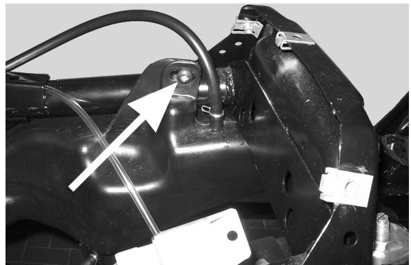
See also
Frame central cover
Front mudguard
- Leaving the front wheel assembled, disassemble the steering tube from the vehicle
- Unscrew the 3 screws securing it and remove them
- Remove the speedometer transmission and brake hose, then remove the mudguard
N.B.
WHEN REASSEMBLING BE CAREFUL TO POSI-TION THE 2 METAL GROMMETS TO AVOID ANY RUBBING AGAINST THE WHEEL.
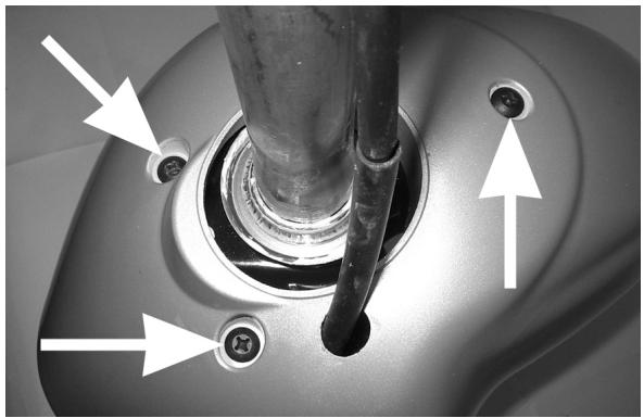
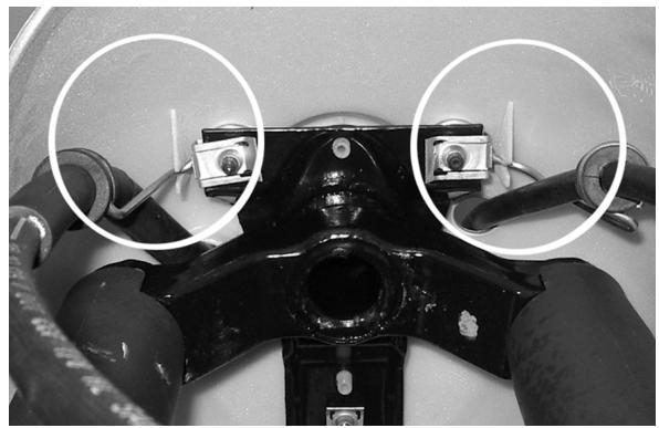
See also
Removal
Top-case
Front
Disassembling the inner shield fairing (glove box assy.)
- Remove the two screws from inside the glove box.
- Remove the two screws at the lower part of the inner shield fairing
- Remove the two screws located behind the front grille.
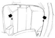
INDEX OF TOPICS
PRE-DELIVERY
PRECON
Aesthetic inspection
Predelivery checks:
- Paintwork
- Mating of plastics
-Scratches
- Dirt
Tightening torques inspection
Locks Inspection
- Safety locks
- Fixing screws
Safety locks:
| Rear shock absorber top tightening | 20 ÷ 25 N·m |
| Rear shock absorber bottom tightening | 33 ÷ 41 N·m |
| Front wheel axle nut | 45 ÷ 50 N·m |
| Wheel hub nut | 75 ÷ 85 N·m |
| Screws fixing the rear wheel rim to the hub | 20 ÷ 25 N·m |
| Oscillating arm pin - Chassis | 64 ÷ 72 N·m |
| Oscillating arm pin - Engine | 33 ÷ 41 N·m |
| Chassis arm-engine arm pin | 33 ÷ 41 N·m |
| Handlebar locking nut | 43÷47 N·m |
| Steering wheel lower ring nut | 10 ± 13 N·m |
| Steering wheel upper ring nut | 30 ± 33 N·m |
Electrical system
Electric System:
CAUTION
TO ENSURE MAXIMUM PERFORMANCE, THE BATTERY MUST BE CHARGED BEFORE USE. INADEQUATE CHARGING OF THE BATTERY BEFORE IT IS FIRST USED WITH A LOW LEVEL OF THE ELECTROLYTE SHORTENS THE LIFE OF THE BATTERY.
WARNING
BEFORE RECHARGING THE BATTERY, REMOVE THE PLUGS OF EACH ELEMENT. KEEP SPARKS AND FREE FLAMES AWAY FROM THE BATTERY WHILE RECHARGING. REMOVE THE BATTERY FROM THE VEHICLE DISCONNECTING THE NEGATIVE TERMINAL FIRST.
CAUTION
WHEN INSTALLING THE BATTERY, FIRST FIX THE POSITIVE CABLE AND THEN THE NEGATIVE CABLE.
WARNING
THE BATTERY ELECTROLYTE IS POISONOUS AND CAUSES SEVERE BURNS AS IT CONTAINS SULPHURIC ACID. AVOID CONTACT WITH THE EYES, THE SKIN AND CLOTHING. IN CASE OF CONTACT WITH THE EYES OR THE SKIN, RINSE GENEROUSLY WITH WATER FOR ABOUT 15 MINUTES AND IMMEDIATELY SEEK MEDICAL ATTENTION. IN CASE OF INGESTION, IMMEDIATELY DRINK LARGE QUANTITIES OF WATER OR VEGETABLE OIL. IMMEDIATELY SEEK MEDICAL ATTENTION. BATTERIES PRODUCE EXPLOSIVE GASES. KEEP THEM AWAY FROM OPEN FLAMES, SPARKS AND CIGARETTES. IF THE BATTERY IS CHARGED IN A CLOSED PLACE, TAKE CARE TO ENSURE ADEQUATE VENTILATION. ALWAYS PROTECT THE EYES WHEN WORKING CLOSE TO BATTERIES. KEEP OUT OF REACH OF CHILDREN
CAUTION
NEVER USE FUSES HAVING A HIGHER RATING THAN RECOMMENDED. USING A FUSE OF UNSUITABLE RATING MAY SERIOUSLY DAMAGE THE VEHICLE OR EVEN CAUSE A FIRE.
Levels check
Level check
- Hydraulic braking system fluid level
Rear hub oil level
- Engine coolant level
Road test
Road test:
- Cold starting
- Operation of instruments
- Operation of throttle control
- Stability during acceleration and braking
- Operation of front and rear brakes
- Operation of front and rear suspensions
- Abnormal noise from vehicle
Static test
Static inspection after test on the road:
- Hot start
- Starter operation
- Idel speed hold (by turning the handlebar)
- Even steering wheel rotation
- Leaks, if any
CAUTION
CHECK THE INFLATING PRESSURES WHEN THE TYRES ARE AT AMBIENT TEMPERATURE.
CAUTION
NOT EXCEED THE RECOMMENDED INFLATING PRESSURES AS THE TYRES MAY BURST.
Functional inspection
Functional Check:
Braking system (hydraulic)
- Lever stroke
Braking system (mechanical)
- Lever stroke
Clutch
- Proper performance check
Engine
- Gas control stroke check Miscellaneous
- Document check
- Check of chassis no. and engine no.
- Ancillary tools
- Plate assembly
- Check of locks
- Tyre pressure check
- Installation of rear-view mirrors and optional fixtures
INDEX OF TOPICS
TIME
TEMP
This section describes the amount of time it takes for repair operations.
The description, code and amount of time for each operation are indicated.
Engine
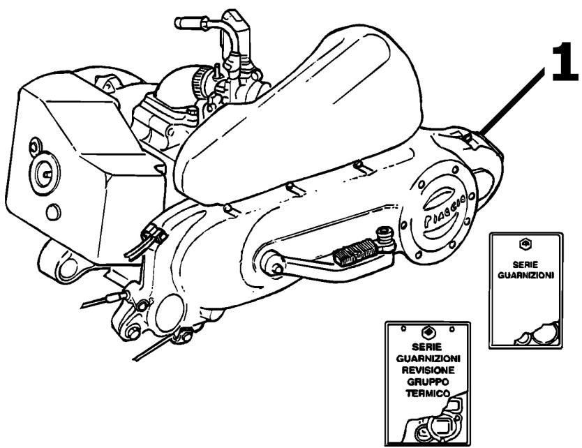
ENGINE
| Code | Action | Duration |
| 1 | 001001 | Engine to frame - Disassembly and reassembly | 90' |
Crankcase
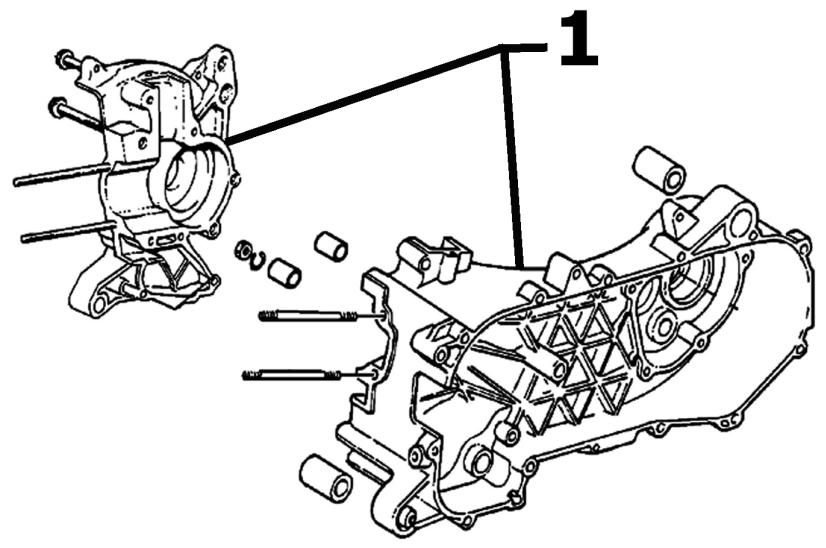
CRANKCASE
| Code | Action | Duration |
| 1 | 001133 | Engine crankcase - Replacement | 190' |
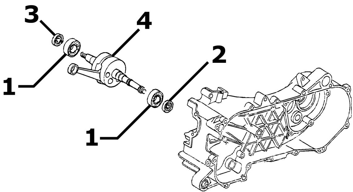
Crankshaft
DRIVING SHAFT
| Code | Action | Duration |
| 1 | 001118 | Main bearings - Replacement | 170' |
| 2 | 001100 | Oil seal clutch side - Replacement | 55' |
| 3 | 001099 | Oil seal flywheel side - Replacement | 50' |
| 4 | 001117 | Crankshaft - Replacement | 170' |
Cylinder assay.
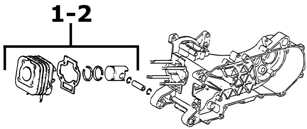
PISTON CYLINDER
| Code | Action | Duration |
| 1 | 001002 | Piston cylinder - Replacement | 55' |
| 2 | 001007 | Cylinder, piston - Overhaul/Cleaning | 50' |
Cylinder head assay.
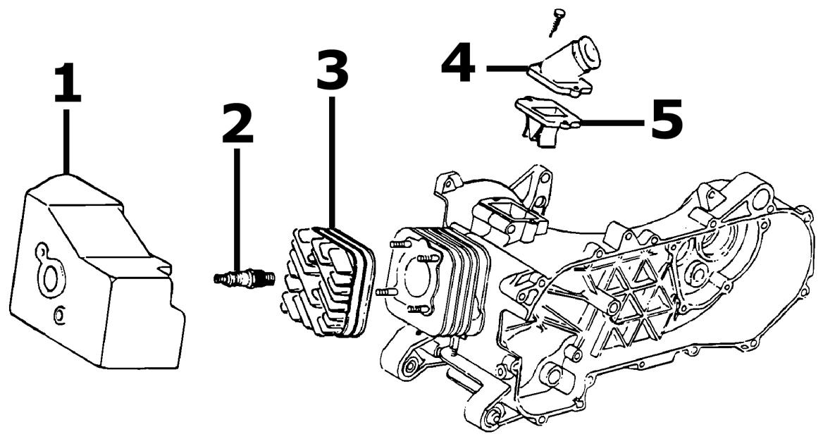
HEAD
| Code | Action | Duration |
| 1 | 001097 | Cooling hood - Replacement | 25' |
| 2 | 001093 | Spark plug - Replacement | 10' |
| 3 | 001126 | Head - Replacement | 50' |
| 4 | 001013 | Intake manifold - Replacement | 40' |
| 5 | 001178 | Reed valve assembly - Replacement | 45' |
Driven pulley
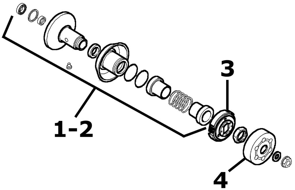
DRIVEN PULLEY - CLUTCH
| Code | Action | Duration |
| 1 | 001012 | Driven pulley - Overhaul | 50' |
| 2 | 001110 | Driven pulley - Replacement | 35' |
| 3 | 001022 | Clutch - Replacement | 40' |
| 4 | 001155 | Clutch bell housing - Re-placement | 20' |
Oil pump
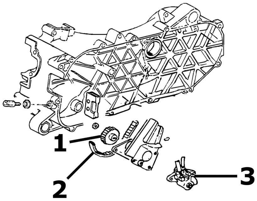
OIL PUMP
| Code | Action | Duration |
| 1 | 001028 | Mixer drive gear - Replacement | 55' |
| 2 | 001019 | Mixer belt - Replacement | 30' |
| 3 | 001018 | Mixer - Replacement | 40' |
Driving pulley
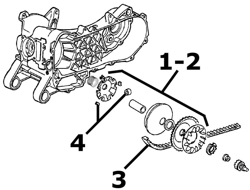
DRIVING PULLEY
| Code | Action | Duration |
| 1 | 001066 | Driving pulley - Disassembly and reassembly | 25' |
| 2 | 001086 | Driving half pulley - Replacement | 25' |
| 3 | 001011 | Driving belt - Replacement | 25' |
| 4 | 001177 | Rollers / Variator track shoes - Replacement | 30' |
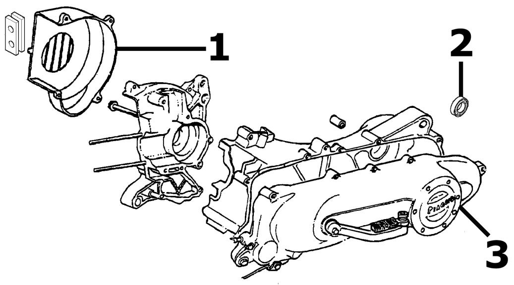
Transmission cover
TRANSMISSION COVER
| Code | Action | Duration |
| 1 | 001087 | Flywheel cover - Replacement | 25' |
| 2 | 001135 | Transmission cover bearing - Replacement | 30' |
| 3 | 001096 | Transmission casing cover - Replacement | 20' |
Flywheel magneto

1
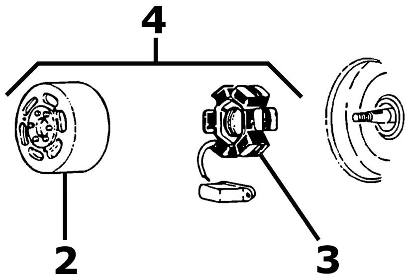
FLYWHEEL - FAN
| Code | Action | Duration |
| 1 | 001109 | Cooling fan - Replacement | 30' |
| 2 | 001173 | Rotor - Replacement | 50' |
| 3 | 001067 | Stator - Disassembly and re-assembly | 50' |
| 4 | 001058 | Flywheel - Replacement | 50' |
Carburettor
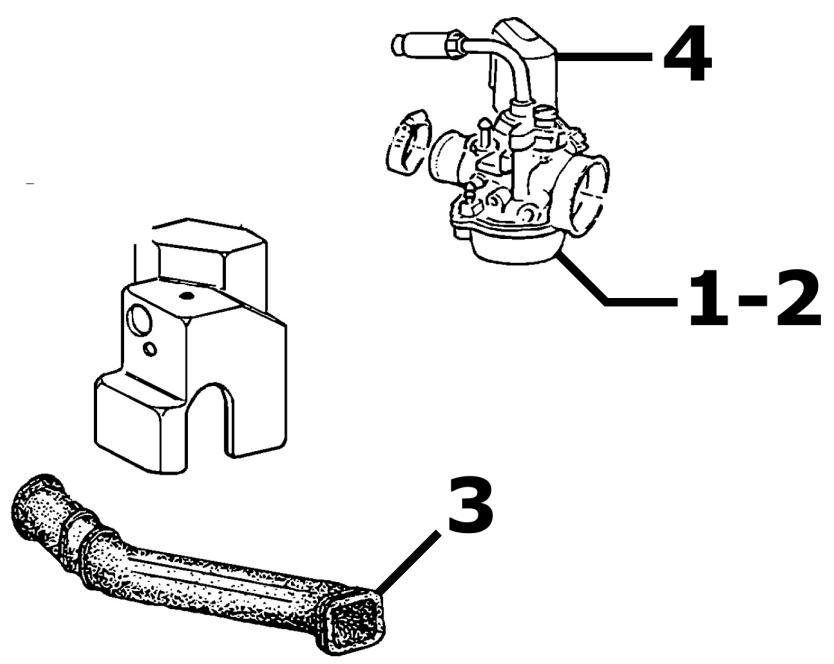
CARBURATOR
| Code | Action | Duration |
| 1 | 001008 | Carburettor - Overhaul | 50' |
| 2 | 001063 | Carburettor - Replacement | 35' |
| 3 | 001081 | Automatic starter device - Replacement | 30' |
| 4 | 007020 | Carburettor heating mani-folds - Replacement | 20' |
Exhaust pipe
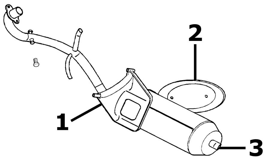
MUFFLER
| Code | Action | Duration |
| 1 | 001009 | Silencer - Replacement | 30' |
| 2 | 001095 | Silencer guard - Replacement | 10' |
| 3 | 001136 | Exhaust emissions - Adjustment | 20' |
Air cleaner
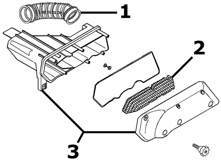
AIR FILTER
| Code | Action | Duration |
| 1 | 004122 | Carburettor filter manifold - Replacement | 25' |
| 2 | 001014 | Air Filter - Replacement | 30' |
| 3 | 001015 | Air filter box - Replacement | 30' |
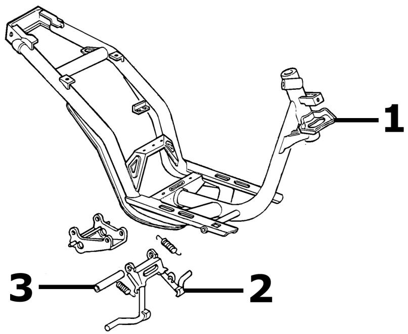
Centre-stand
STAND
| Code | Action | Duration |
| 1 | 004004 | Stand - Replacement | 20' |
| 2 | 001053 | Stand pin - Replacement | 20' |
Legshield spoiler
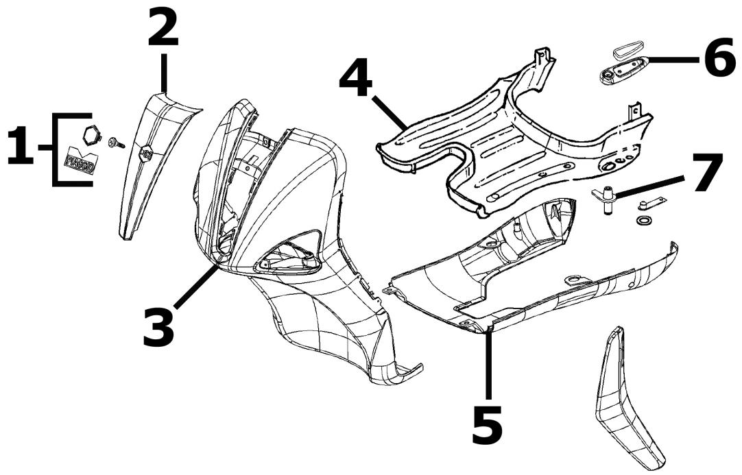
MUFFLER - GLOVE COMPARTMENT
| Code | Action | Duration |
| 1 | 004159 | Stickers - Replacement | 10' |
| 2 | 004149 | Front shield - Painting | 10' |
| 3 | 004064 | Front shield, front section - Removal and refitting | 95' |
| 4 | 004015 | Footrest - Disassembly and reassembly | 25' |
| 5 | 004053 | Spoiler - Replacement | 50 |
| 6 | 004079 | Rear footrest - Replacement | 45' |
| 7 | 004143 | Foot-peg mounting bracket - Replacement | 45' |
Rear cover
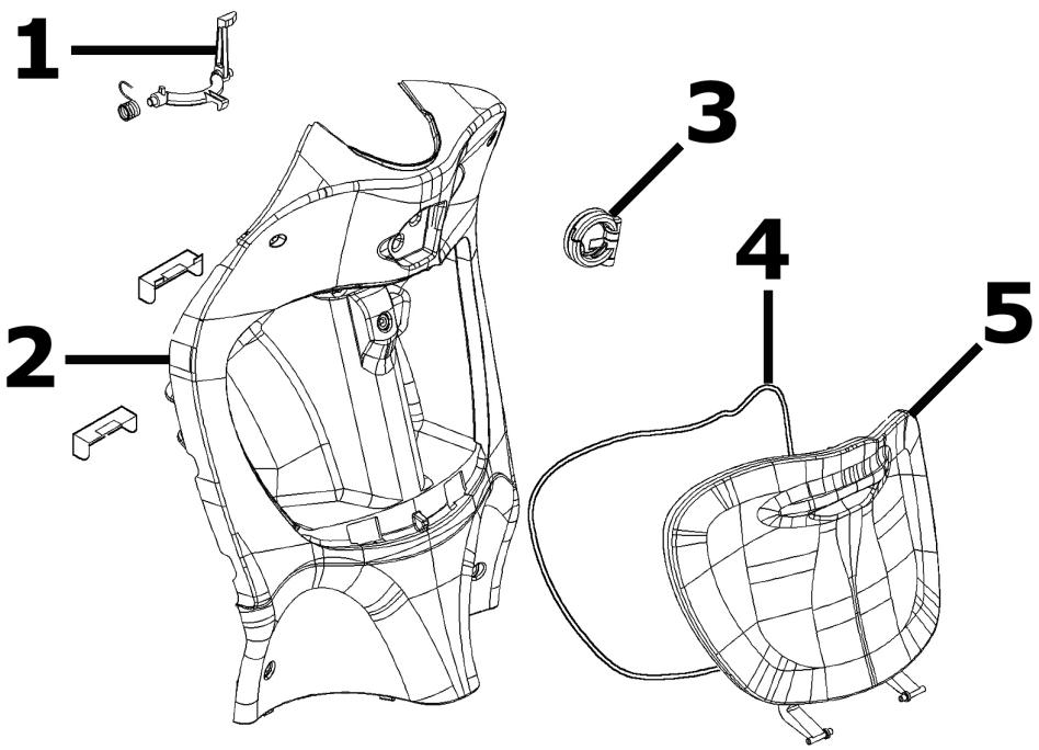
REAR COVER
| Code | Action | Duration |
| 1 | 004174 | Glove-box remote opening linkage - Replacement | 20' |
| 2 | 004065 | Knee-guard - Removal and refitting | 30' |
| 3 | 004131 | Rear rack mounting bracket - Replacement | 20' |
| 4 | 004082 | Glove-box packing - Re- placement | 10' |
| 5 | 004081 | Glove compartment door - Replacement | 35' |
Central cover
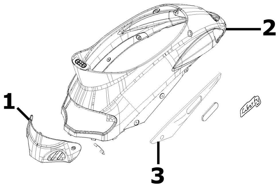
CENTRAL COVER
| Code | Action | Duration |
| 1 | 004059 | Spark plug inspection flap - Replacement | 10' |
| 2 | 004085 | Side panel (1) - Replacement | 10' |
| 3 | 004106 | Undersaddle band - Re- placement | 20' |
Underseat compartment
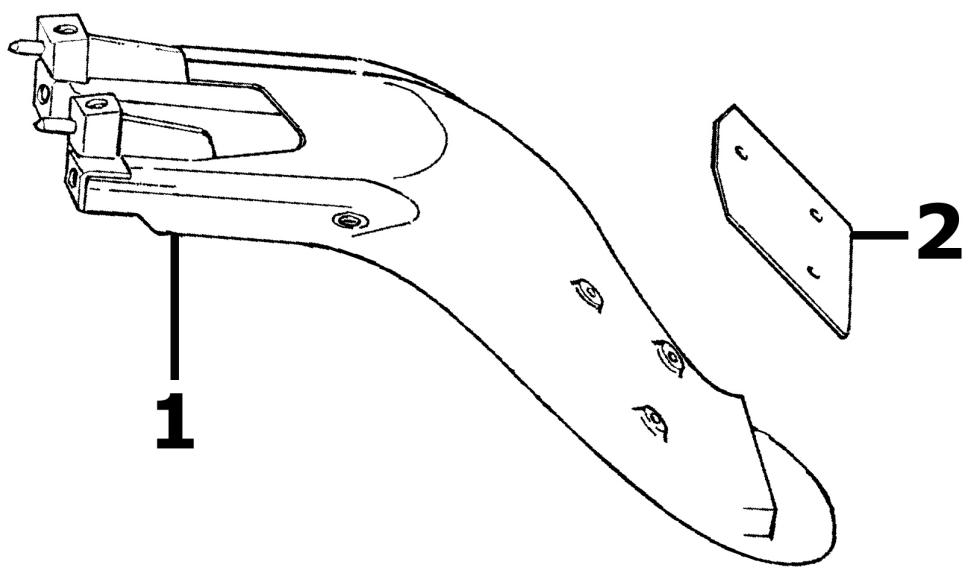
HELMET COMPARTMENT
| Code | Action | Duration |
| 1 | 004136 | License plate holder mount- ing bracket - Replacement | 25' |
| 2 | 005048 | Plate holder - Replacement | 10' |
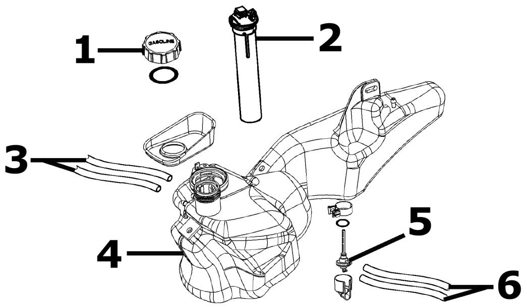
Fuel tank
FUEL TANK
| Code | Action | Duration |
| 1 | 004168 | Fuel filler cap - Replacement | 10' |
| 2 | 005010 | Fuel tank float - Replacement | 45' |
| 3 | 004109 | Fuel tank breather - Replacement | 40' |
| 4 | 004005 | Fuel tank - Replacement | 40' |
| 5 | 004007 | Mixture cock - Replacement | 25' |
| 6 | 004112 | Cock-carburettor pipe - Replacement | 10' |
serbatoio olio
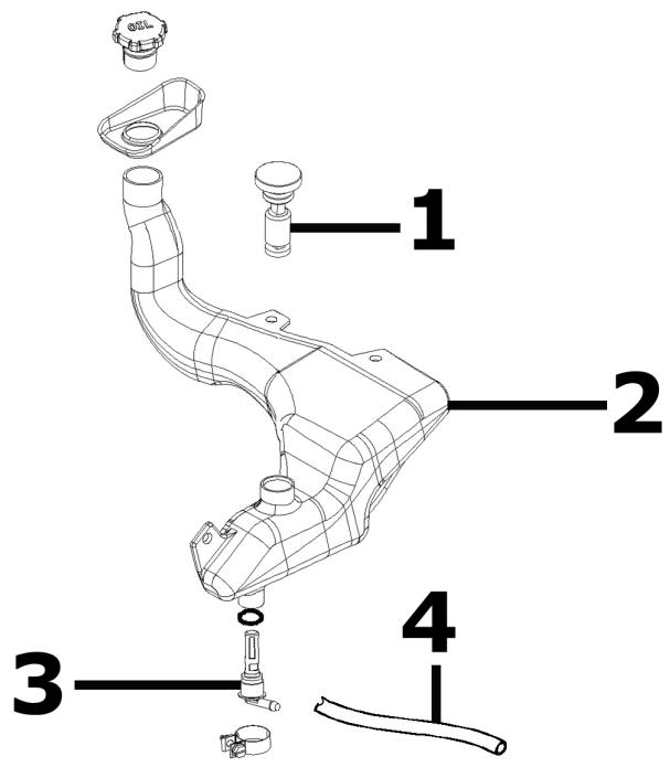
OIL TANK
| Code | Action | Duration |
| 1 | 005018 | Oil tank float - Replacement | 45' |
| 2 | 004017 | Oil tank - Replacement | 40' |
| 3 | 004095 | Oil tank tap - Replacement | 15' |
| 4 | 004091 | Oil tank line - Replacement | 15' |
Rear shock-absorber
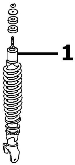
REAR SHOCK ABSORBER
| Code | Action | Duration |
| 1 | 003007 | Rear shock absorber - Disas-sembly and reassembly | 60' |
Steering column bearings
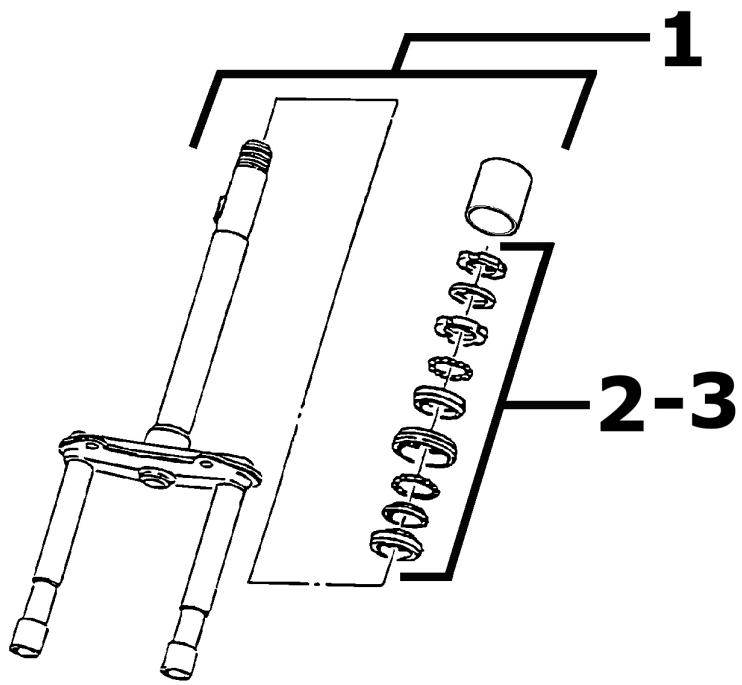
STEERING FIFTH WHEELS
| Code | Action | Duration |
| 1 | 003051 | Fork assembly - Replacement | 75' |
| 2 | 003002 | Steering fifth wheels - Replacement | 65' |
| 3 | 003073 | Steering play - Adjustment | 40' |
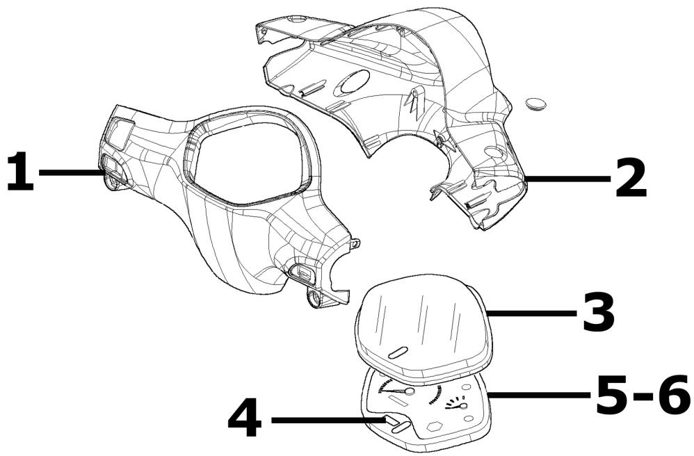
Handlebar covers
ODOMETER - HANDLEBAR COVERS
| Code | Action | Duration |
| 1 | 004019 | Handlebar rear side - Re- placement | 10' |
| 2 | 004018 | Handlebar front section - Re- placement | 15' |
| 3 | 005078 | Odometer plastic cover - Re- placement | 20' |
| 4 | 005076 | Clock \ Battery - Replacement | 25' |
| 5 | 005014 | Odometer - Substitution | 20' |
| 6 | 005038 | Dashboard warning lights - Replacement | 15' |
Handlebar components
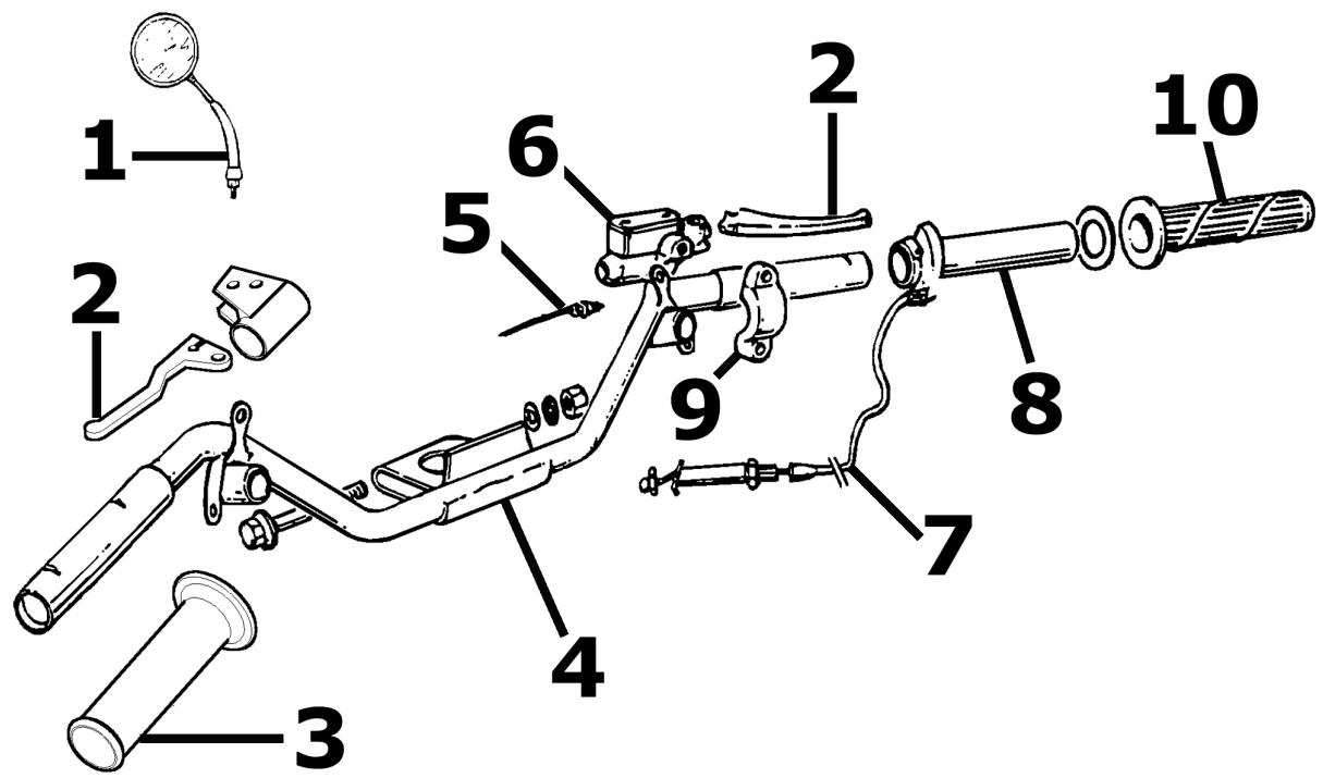
HANDLEBAR COMPONENTS
| Code | Action | Duration |
| 1 | 004066 | Rearview mirrors - Replacement | 10' |
| 2 | 002037 | Complete gas control - Replacement | 20' |
| 3 | 002071 | Left knob - Replacement | 10' |
| 4 | 003001 | Handlebar - Removal and re-fitting | 40' |
| 5 | 005017 | Stop light switch - Replacement | 15' |
| 6 | 002024 | Brake pump - Removal and reinstallation | 40' |
| 7 | 002054 | Throttle or splitter cable as-sembly - Replacement | 40' |
| 8 | 002060 | Complete gas control - Re-placement | 15' |
| 9 | 004162 | Mirror U-bolt and/or brake pump fitting - Replacement | 35' |
| 10 | 002059 | Right knob - Replacement | 10' |
Swing-arm
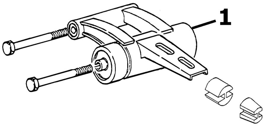
SWINGING ARM
| Code | Action | Duration |
| 1 | 001072 | Engine-frame connection swing arm - Replacement | 60' |
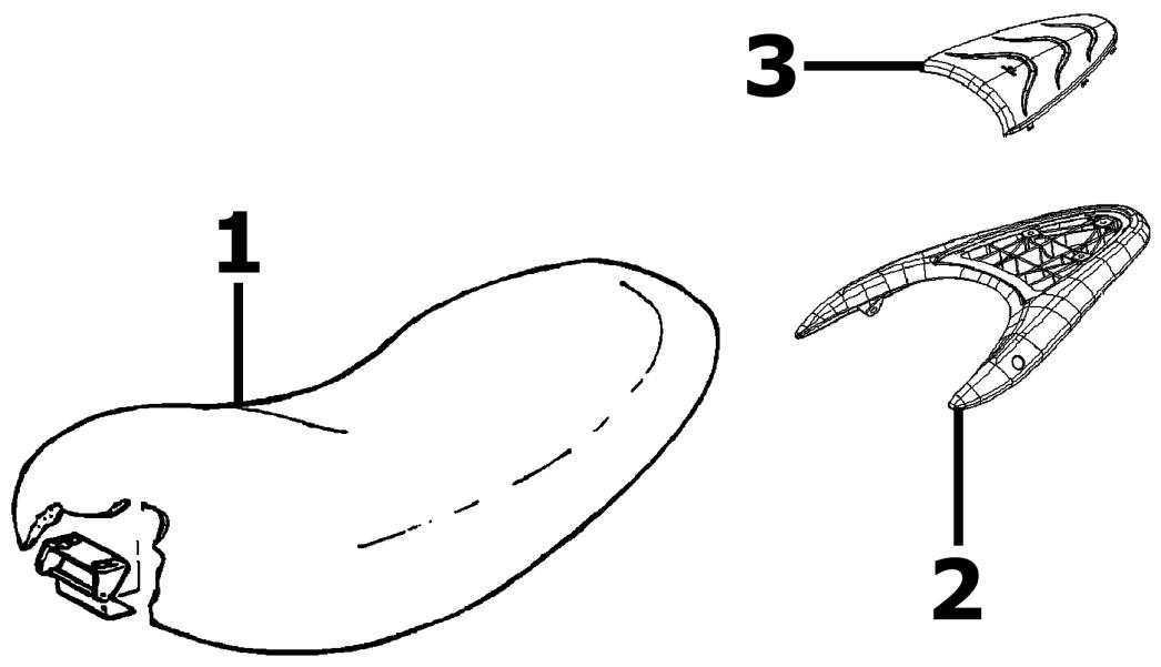
Seat
SADDLE
| Code | Action | Duration |
| 1 | 004003 | Saddle - Replacement | 10' |
| 2 | 004008 | Carrier - replacement | 10' |
| 3 | 004062 | Rear rack cover - Replacement | 10' |
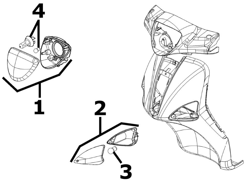
Turn signal lights
REAR RED LAMP
| Code | Action | Duration |
| 1 | 005002 | Headlight - Replacement | 15' |
| 2 | 005012 | Front direction indicators - Replacement | 15' |
| 3 | 005067 | Front direction indicator bulb - Replacement | 10' |
| 4 | 005008 | Front headlights - Replacement | 10' |
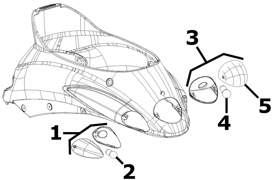
LAMP CLUSTER
| Code | Action | Duration |
| 1 | 005022 | Rear turn signal light- Replacement | 15' |
| 2 | 005068 | Rear turn indicator bulb - Replacement | 10' |
| 3 | 005005 | Taillight - Replacement | 20' |
| 4 | 005066 | Rear light bulbs - Replacement | 10' |
| 5 | 005028 | Rear optical unit glass - Replacement | 10' |
Front wheel
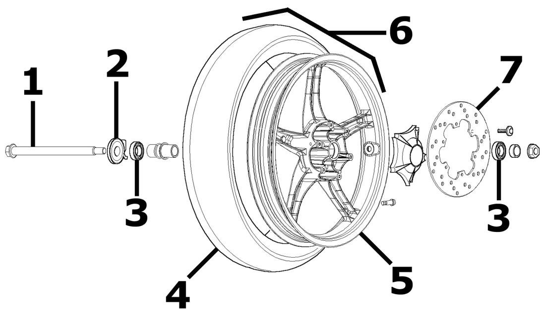
FRONT WHEEL
| Code | Action | Duration |
| 1 | 003038 | Front wheel spindle - Re-moval and refitting | 45' |
| 2 | 002011 | Odometer drive gear - Re-placement | 30' |
| 3 | 003040 | Front wheel bearings - Re-placement | 50' |
| 4 | 003047 | Front tyre - Replacement | 25' |
| 5 | 003037 | Front wheel rim - Removal and refitting | 20' |
| 6 | 004123 | Front wheel - Replacement | 25' |
| 7 | 002041 | Brake disc - Replacement | 35' |
Rear wheel
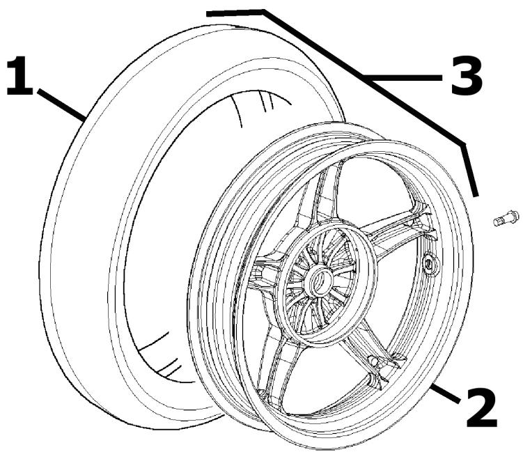
REAR WHEEL
| Code | Action | Duration |
| 1 | 004126 | Rear tyre - Replacement | 40' |
| 2 | 001071 | Rear wheel rim - Removal and refitting | 40' |
| 3 | 001016 | Rear wheel - Replacement | 20' |
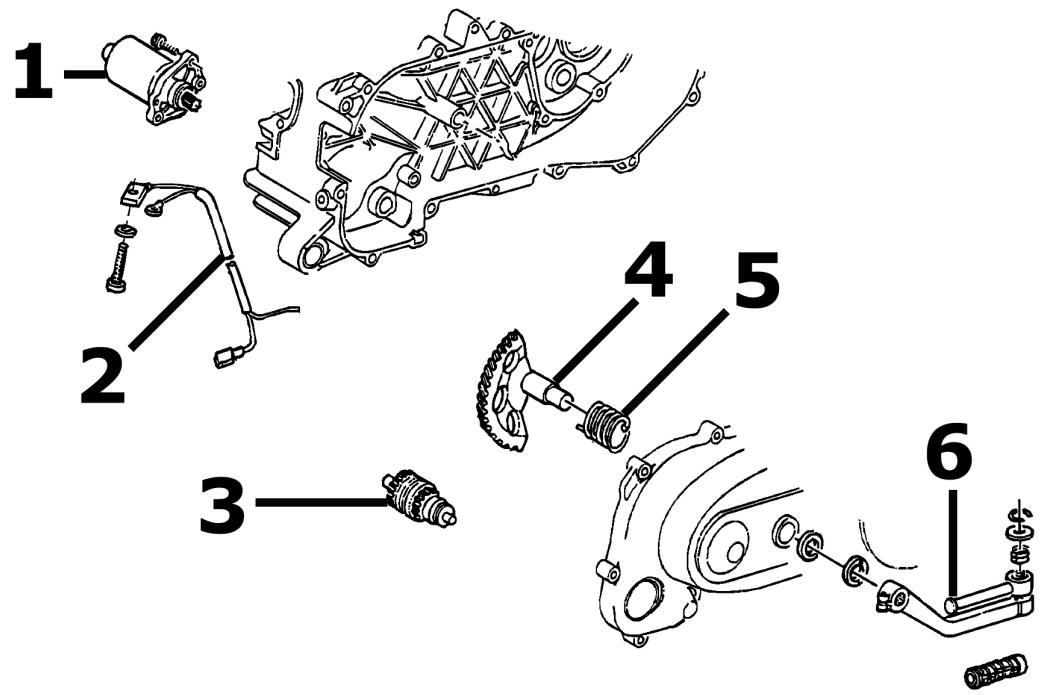
Electric start
ELECTRIC START
| Code | Action | Duration |
| 1 | 001020 | Starter engine - Replacement | 25' |
| 2 | 005045 | Starting motor cables - Replacement | 20' |
| 3 | 001017 | Starter pinion - Replacement | 25' |
| 4 | 001021 | Kick starter - Overhaul | 25' |
| 5 | 008008 | Starting sector spring - Replacement | 45' |
| 6 | 001084 | Starting lever - Replacement | 10' |
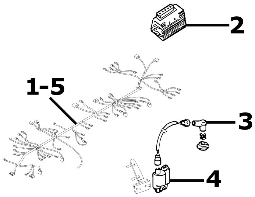
Electric devices
ELECTRIC DEVICES
| Code | Action | Duration |
| 1 | 005001 | Electric circuit - Replacement | 140' |
| 2 | 005009 | Voltage regulator - Replacement | 30' |
| 3 | 001094 | Spark plug cap - Replacement | 10' |
| 4 | 001023 | Controller - Replacement | 30' |
| 5 | 005114 | Electric circuit - Overhaul | 30' |
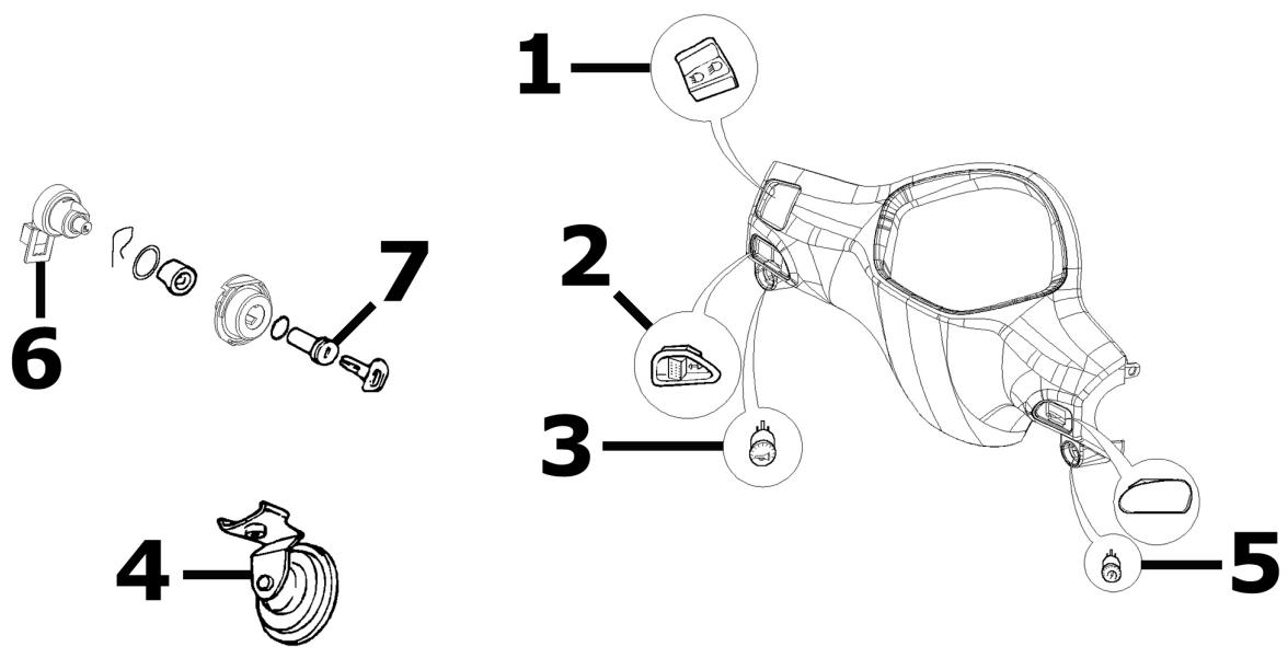
ELECTRICAL DEVICES
| Code | Action | Duration |
| 1 | 005006 | Light or flashing light switch - Replacement | 25' |
| 2 | 005039 | Light switch - Replacement | 25' |
| 3 | 005040 | Horn button - Replacement | 25' |
| 4 | 005003 | Electric horn - Replacement | 15' |
| 5 | 005041 | Starting device push button - Replacement | 25' |
| 6 | 005016 | Key switch - Replacement | 55' |
| 7 | 004096 | Locks series - Replacement | 35' |
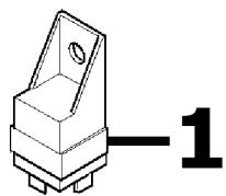

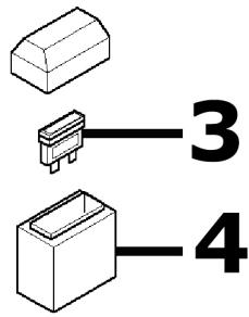
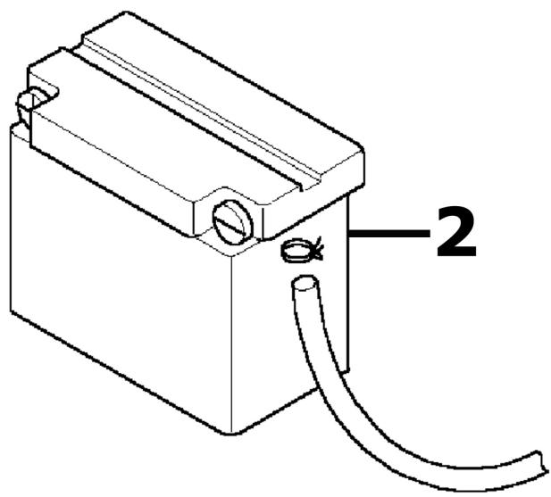
ELECTRICAL DEVICES
| Code | Action | Duration |
| 1 | 005007 | Battery - Replacement | 15' |
| 2 | 005011 | Start-up remote control switch - Replacement | 30' |
| 3 | 005052 | Fuse (1) - Replacement | 20' |
| 4 | 005054 | Fuse carrier (1) - Replacement | 10' |
trasmissioni
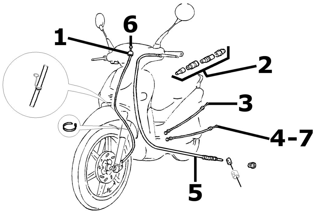
TRANSMISSIONS
| Code | Action | Duration |
| 1 | 002051 | Odometer transmissions as-sembly - Replacement | 30' |
| 2 | 002012 | Splitter - Replacement | 30' |
| 3 | 002057 | Splitter-carburettor cable as-sembly - Replacement | 30' |
| 4 | 002058 | Mixer splitter cable assembly - Replacement | 35' |
| 5 | 002053 | Rear brake transmissions as-sembly - Replacement | 35' |
| 6 | 002049 | Odometer cable - Replacement | 15' |
| 7 | 003061 | Throttle cable - Adjustment | 5' |
Brake callipers
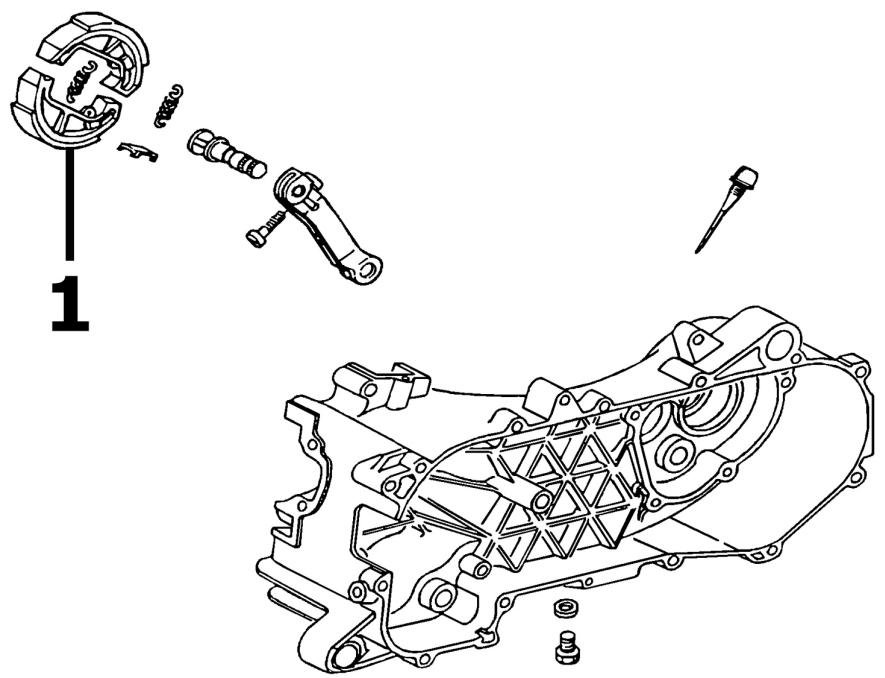
FRONT BRAKE CALIPER
| Code | Action | Duration |
| 1 | 002002 | Rear brake pads/shoes - Wear check | 40' |
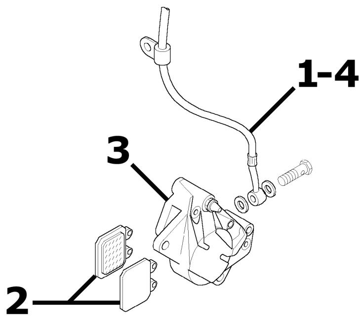
BRAKE LEVER
| Code | Action | Duration |
| 1 | 002021 | Front brake line - Replace- | 45' |
| ment |
| 2 | 002007 | Front brake shoes/pads - Re- moval and refitting | 15' |
| 3 | 002039 | Front brake calliper - Remov- al and refitting | 35' |
| 4 | 002047 | Front brake liquid and circuit bleeding - Replacement | 50' |
Front mudguard
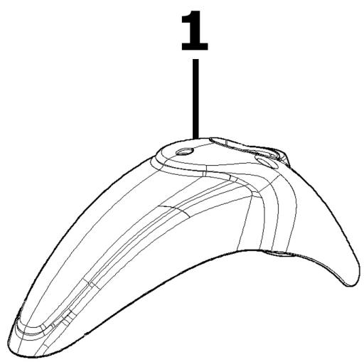
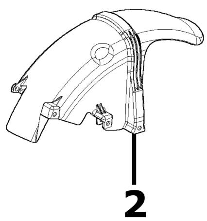
REAR MUDGUARD
| Code | Action | Duration |
| 1 | 004009 | Rear mudguard - Replacement | 15' |
| 2 | 004002 | Front mudguard - Replacement | 60' |
Steering column
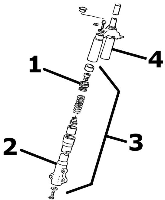
STEERING
| Code | Action | Duration |
| 1 | 003048 | Fork oil seal - Replacement | 70' |
| 2 | 003076 | Fork leg - Replacement | 70' |
| 3 | 003079 | Fork stanchion - Replacement | 70' |
| 4 | 003010 | Front suspension - Overhaul | 95' |
Helmet bay
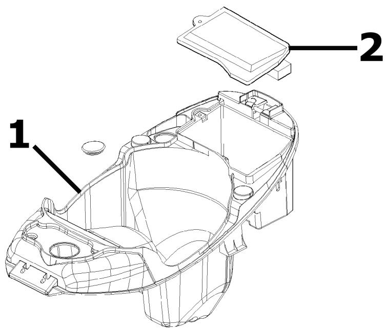
HELMET CARRIER
| Code | Action | Duration |
| 1 | 004016 | Helmet compartment - Disas-sembly and reass | 35' |
| 2 | 005046 | Battery cover - Replacement | 10' |

Rear wheel axle
REAR WHEEL AXLE
| Code | Action | Duration |
| 1 | 001156 | Reduction gear cover - Replacement | 30' |
| 2 | 004125 | Rear wheel axle - Replacement | 30' |
| 3 | 001010 | Reduction gear - Overhaul | 60' |
| 4 | 003065 | Gearcase oil - Replacement | 20' |
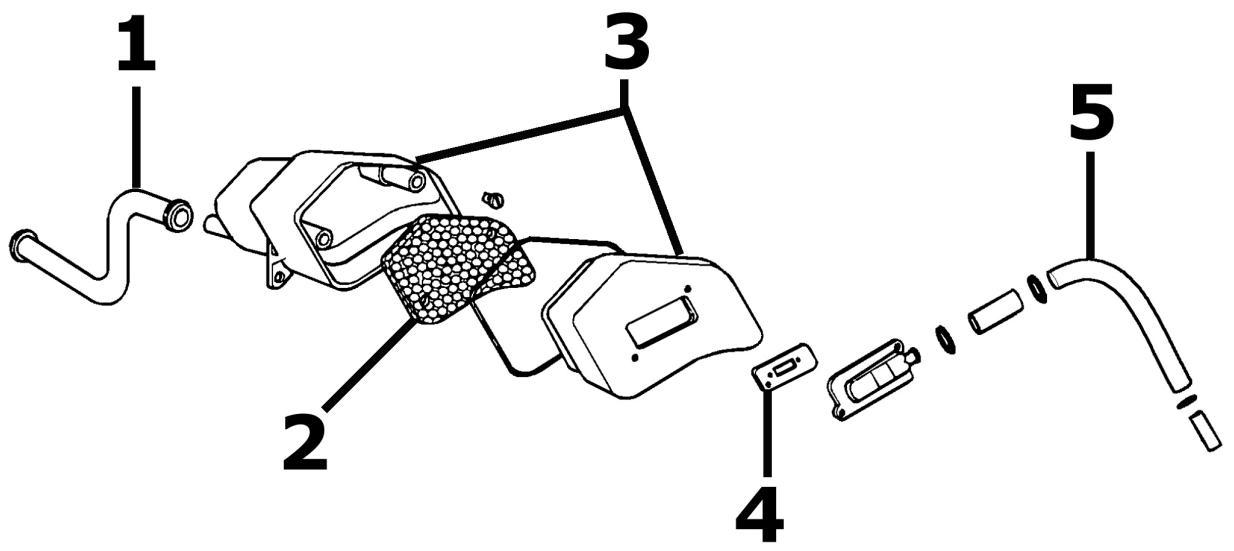
Secondary air box
SECONDARY AIR BOX
| Code | Action | Duration |
| 1 | 001164 | Crankcase secondary air junction - Replacement | 40' |
| 2 | 001161 | Secondary air filter- Replacement / Cleaning | 15' |
| 3 | 001162 | Secondary air box - Replacement | 40' |
| 4 | 001163 | Exhaust secondary air junc-tion - Replacement | 40' |
| 5 | 001165 | Secondary air valve - Re- placement | 15' |