
SL1200LTD - Platine vinyle PANASONIC - Notice d'utilisation et mode d'emploi gratuit
Retrouvez gratuitement la notice de l'appareil SL1200LTD PANASONIC au format PDF.
| Type de produit | Platine vinyle |
| Marque | Panasonic |
| Modèle | SL1200LTD |
| Dimensions (L × H × P) | 453 × 162 × 360 mm |
| Poids | 12,5 kg |
| Alimentation | 110-120 / 220-240 V, 50/60 Hz |
| Vitesses | 33 1/3 et 45 tr/min |
| Entraînement | Quartz direct drive |
| Moteur | Moteur sans balais à courant continu |
| Plateau | Aluminium moulé, diamètre 332 mm, poids 2 kg |
| Couple de démarrage | 1,5 kg·cm |
| Temps de démarrage | 0,7 s (de l'arrêt à 33 1/3 tr/min) |
| Système de freinage | Frein électronique |
| Pleurage et scintillement | 0,01 % W.R.M.S |
| Rapport signal/bruit (Rumble) | -56 dB (non pondéré), -78 dB (pondéré) |
| Bras de lecture | Universel, longueur effective 230 mm, masse effective 12 g |
| Plage de réglage hauteur du bras | 31,8 - 37,8 mm |
| Porte-cellule | Aluminium moulé, poids 7,5 g, contacts dorés |
| Réglage de l'antidérapant | De 0 à la valeur de pression de lecture |
| Éclairage de pointe | Oui, escamotable |
| Réglage fin de vitesse (Pitch) | ± 8 % avec verrouillage quartz |
| Matériau du châssis | Aluminium moulé et base en caoutchouc lourd |
| Nettoyage | Utiliser un chiffon doux et sec. Éviter alcool, benzine, diluant. |
| Sécurité | Ne pas toucher la fiche avec les mains mouillées ; débrancher en cas de déversement de liquide. |
FOIRE AUX QUESTIONS - SL1200LTD PANASONIC
Questions des utilisateurs sur SL1200LTD PANASONIC
0 question sur cet appareil. Repondez a celles que vous connaissez ou posez la votre.
Poser une nouvelle question sur cet appareil
Téléchargez la notice de votre Platine vinyle au format PDF gratuitement ! Retrouvez votre notice SL1200LTD - PANASONIC et reprennez votre appareil électronique en main. Sur cette page sont publiés tous les documents nécessaires à l'utilisation de votre appareil SL1200LTD de la marque PANASONIC.
MODE D'EMPLOI SL1200LTD PANASONIC
Technics
Turntable System
SL-1200LTD
Operating instructions
Note:
The "EB" indication shown on the packing case indicates United Kingdom.
Before operating this set, please read these instructions completely.
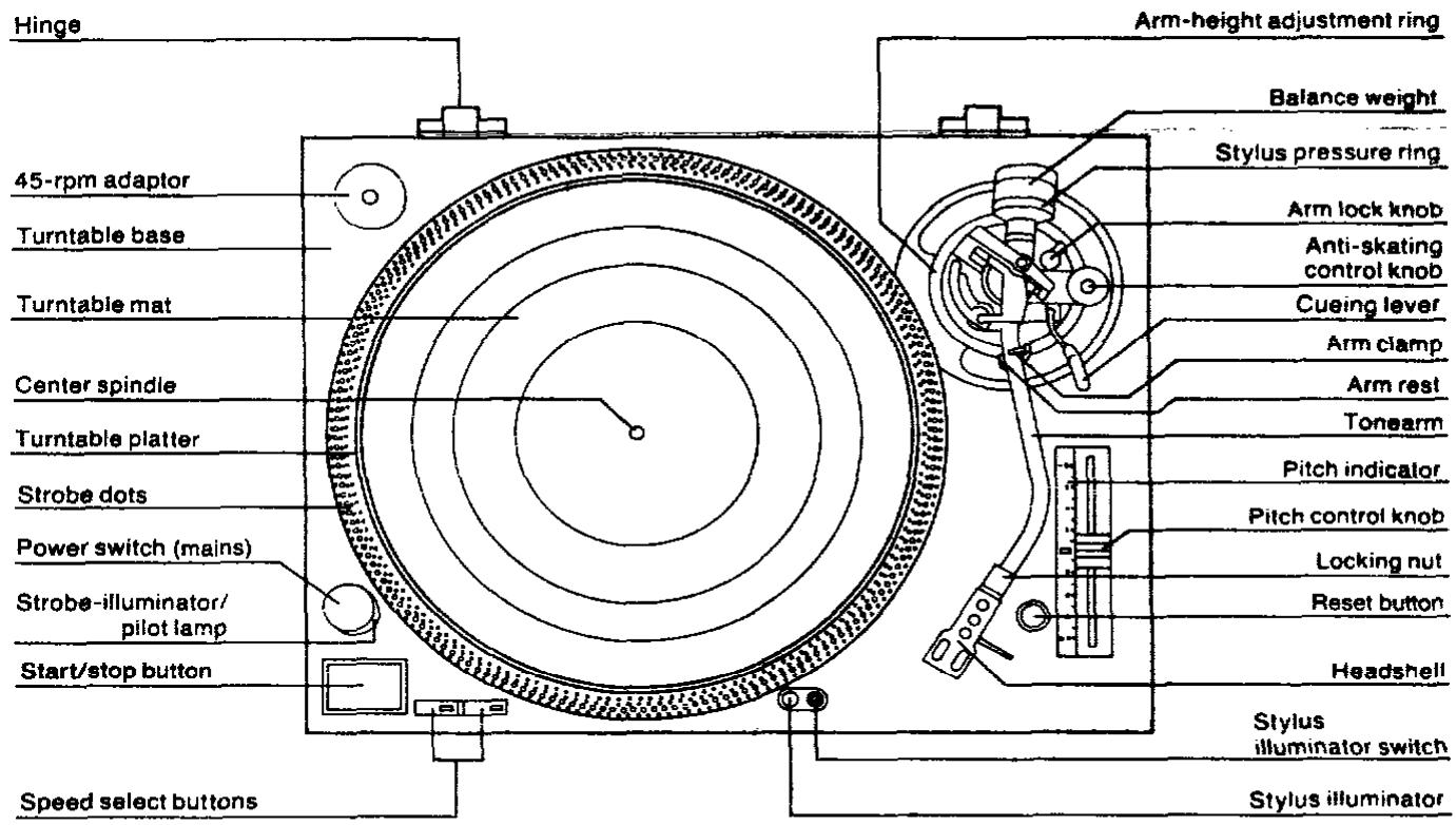
Parts identification
1
nected to letter L or
wires be jg. marked

Assembly and set-up
are)
Caution for AC mains lead (For United Kingdom)
("EB" area code model only)
The configuration of AC power supply cord has been changed.
For your safety, please read the following text carefully.
This appliance is supplied with a moulded three pin mains plug for your safety and convenience.
A 5-ampere fuse is fitted in this plug.
Should the fuse need to be replaced please ensure that the replacement fuse has a rating of 5-ampere and that it is approved by ASTA or BSI to BS1362.
Check for the ASTA mark or the BSI mark on the body of the fuse.
If the plug contains a removable fuse cover you must ensure that it is refitted when the fuse is replaced.
If you lose the fuse cover the plug must not be used until a replacement cover is obtained.
A replacement fuse cover can be purchased from your local dealer.
CAUTION!
IF THE FITTED MOULDED PLUG IS UNSUITABLE FOR THE SOCKET OUTLET IN YOUR HOME THEN THE FUSE SHOULD BE REMOVED AND THE PLUG CUT OFF AND DISPOSED OF SAFELY.
THERE IS A DANGER OF SEVERE ELECTRICAL SHOCK IF THE CUT OFF PLUG IS INSERTED INTO ANY 13-AMPERE SOCKET.
If a new plug is to be fitted please observe the wiring code as shown below.
If in any doubt please consult a qualified electrician.
IMPORTANT
The wires in this mains lead are coloured in accordance with the following code:
Blue: Neutral
Brown: Live
As the colours of the wires in the mains lead of this appliance may not correspond with the coloured markings identifying the terminals in your plug, proceed as follows:
The wire which is coloured BLUE must be connected to the terminal in the plug which is marked with the letter N or coloured BLACK.
The wire which is coloured BROWN must be connected to the terminal in the plug which is marked with the letter L or coloured RED.
Under no circumstances should either of these wires be connected to the earth terminal of the three pin plug, marked with the letter E or the Earth Symbol 12 .
Before use
Remove the connector cover as follows.
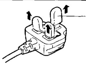
Connector cover
How to replace the fuse
- Remove the fuse cover with a screwdriver.
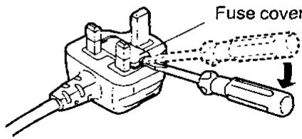
- Replace the fuse and attach the fuse cover.
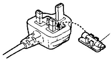
Fuse (5 ampere)
Assembly and set-up


Before use
Caution:
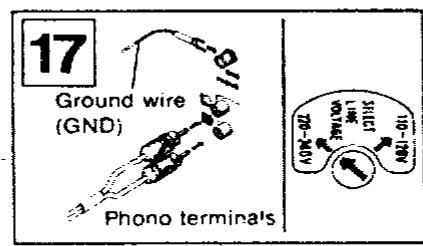
Make sure that the turntable's AC line-voltage selector is matched to your local voltage before connecting the AC power plug (mains.)
Never connect to a DC socket.
If the pre-selected voltage is different from your local voltage, turn the AC line-voltage selector with a screwdriver so that it corresponds to you local voltage.
The AC line-voltage selector is located under the turntable platter. (See Fig. 17.)
Never connect the AC power plug (mains) before assembly has been completed.
Attach the dust cover last, so that assembly and adjustments can be made most conveniently.
Note:
The operating instructions are commonly applicable to units with cartridge and without cartridge, and also to those of different colors.
For the units without cartridge, the cartridge section of the specifications may be neglected.
■ Checklist of parts
Turntable unit 1
Turntable platter 1
Turntable mat 1
Dust cover 1
45-rpm adaptor 1
Balance weight 1
Auxiliary weight 1
Headshell 1
Shell weight 1
Overhang gauge (for the unit without cartridge) 1
Assembly and set-up
Installation of turntable platter
- Place the turntable platter on the center spindle.
Note:
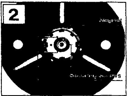
The rotor is connected to the underside of the turntable platter. (The magnet of the motor is attached to the turntable platter.) To maintain optimum performance, extra care should be taken to prevent adhesion of dust or iron filings to the magnet and not to damage the magnet by dropping it.
Do not remove or loosen the screws. Should the position of the fixed magnet be altered by loosening the securing screws, the rated performance of the unit cannot be guaranteed. (See Fig. 2.)
- Place the turntable mat on the platter.
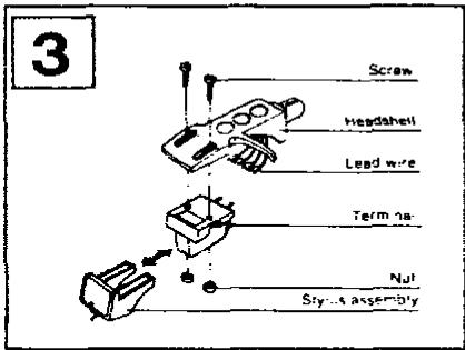
Installation of cartridge (See Fig. 3.)
(For the unit without Cartridge)
When you install a cartridge, refer to the operation Instructions of that cartridge.
During installation, attach the stylus protector to guard the stylus tip from damage.
-
Connect the lead wires to the cartridge terminals. The terminals of most cartridges are color coded. Connect each lead wire to the terminal of the same color. White ( + ) . Left channel ^+ Blue (L - ) . Left channel- Red (R + ) . Right channel ^+ Green ( - ) .Right channel
-
Install a cartridge to the headshell, and tighten it with screws provided with the cartridge.
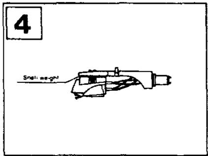
Note:
Use the shell weight only for a lightweight cartridge (less than 6 g). (See Fig. 4.)
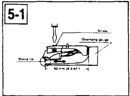
■ Adjustment of overhang (See Fig. 5-1.)
(For the unit with overhang gauge)
-
Insert the headshell into the gauge.
-
Loosen the mounting screws and move the cartridge forward or backward until the stylus tip lines up with the edge of the gauge.
-
Tighten the mounting screws without moving the cartridge.
Note:
Your cartridge is now adjusted for lowest tracking error and minimum distortion.
This gauge is exclusively designed for this tonearm.
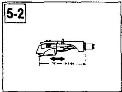
■ Adjustment of overhang (See Fig. 5-2.)
(For the unit without overhang gauge)
The overhang of this unit is 15mm
Loosen the mounting screw and move the cartridge forward or backward until the distance between the stylus tip and the plug becomes 52mm as shown in the picture.
Tighten the mounting screws without moving the cartridge. Adjust horizontal zero balance, stylus pressure and arm-lift height whenever you change the cartridge.
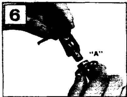
Installation of headshell (See Fig. 6.)
Insert the headshell into the front end of the tubular arm, and turn the locking nut clockwise (In the direction shown by the arrow "A"), with the headshell firmly held horizontally.
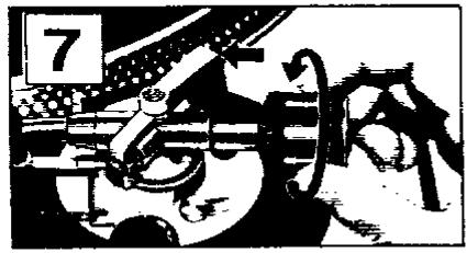
■ Installation of balance weight (See Fig. 7.)
Place the balance weight on the rear shaft of the tonearm.
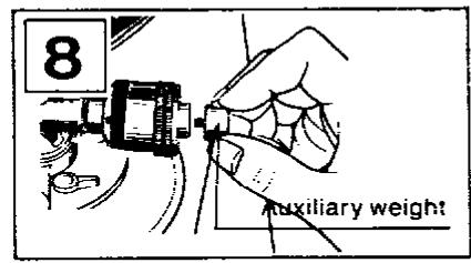
Note:
In case the cartridge weight exceeds 10 g, it is necessary to fix the attached auxiliary weight over the rear shaft of the arm.
With this auxiliary weight in use, it is possible to use any cartridge whose weight is in the range of 9.5-13 g. (See Fig. 8.)
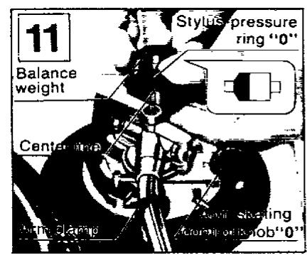
Adjustments of horizontal zero (0) balance and stylus pressure
- Remove the stylus protector, if your cartridge has a detachable one. Be careful not to touch your fingers to the stylus tip.
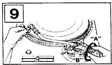
- Release the arm clamp and lift the tonearm from the arm rest to free it.
- Turn the entire balance weight clockwise (indicated by the arrow “A”) or counterclockwise (Indicated by the arrow “B”) until the tonearm is approximately balanced horizontally (floats freely). (See Figs. 9 and 10.)
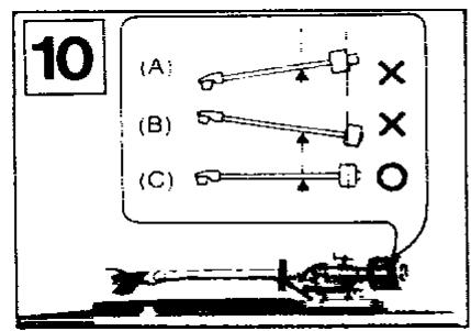
Note:
(A)
Excessive forward advancement of the balance weight causes the cartidge side to be lowered.
(B)
Excessive backward retreatment of the balance weight causes the cartridge side to be raised.
(C)
Upon balancing between the balance weight and cartridge, the tonearm is held horizontal.
For example, if the cartridge height is 17.5 mm, the arm-height adjust ring should be positioned at the intermediate location between 2 and 3 on the scale. (See Fig. 14.)
Caution:
Be sure to lock the tonearm by turning the arm lock knob in the direction indicated by the arrow after finishing the height adjustment for the tonearm.
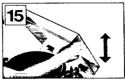
■ Installation of dust cover (See Fig. 15.)
Place the dust cover in position from directly above, holding it at both sides. For detaching the dust cover, be certain first to raise it as illustrated before removal.
Note:
Opening or closing of the dust cover during play should be avoided. This may not only cause undesired vibrations, but also result in skipping of the stylus.
If you must open the dust cover during play, do so as gently as possible.
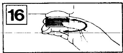
The legs/insulators also have functions for adjusting the height of the turntable unit itself. After installing the unit in the place for use, adjust them to stabilize the main body horizontally. (See Fig. 16.)
During the adjustment of the horizontal zero (0) balance, be careful that the stylus tip of the cartridge does not contact the turntable mat or turntable base.
- After the tonearm is horizontally zero (0) balanced, temporarily refasten the tonearm with the arm clamp.
- Hold the balance weight stationary with one hand as shown in the picture, and rotate only the stylus-pressure ring to bring the numeral "0" of the ring into alignment with the center line on the tonearm rear shaft. (See Fig. 11.)
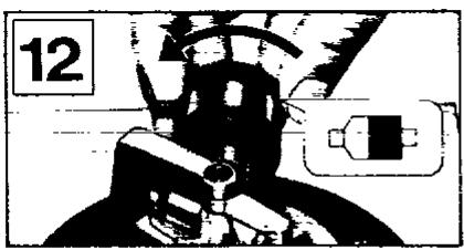
The adjustment of the horizontal zero (0) balance is now completed. - After adjusting the horizontal zero (0) balance, turn the balance weight clockwise in the direction of the arrow and align to the correct stylus pressure. (See Fig. 12.) (Follow the cartridge manufacturer's recommendation.)
As the stylus-pressure ring moves in step with the balance weight, proper stylus pressure can be selected by directly reading the graduated ring.
Adjustment of anti-skating control
Set the anti-skating control knob to the same value as the stylus pressure. (See Fig. 13.)
■ Adjustment of tonearm height (See Fig. 14.)
The height of the tonearm can be adjusted up to 6mm and a scale is provided on the adjust ring in 0.5mm increments. Be sure to set the proper arm height using of the adjust scale and referring to the table below.
| Height of cartridge (mm) (H) | Scale reading on the arm-height adjust ring |
| 15 | 0 |
| 16 | 1 |
| 17 | 2 |
| 18 | 3 |
| 19 | 4 |
| 20 | 5 |
| 21 | 6 |
Placement
Place the unit in a stable and horizontal position, where there is little or no vibration.
Locate the unit as far away from the speakers as possible and isolate the unit from sound radiation from them.
Do not place the unit where it is exposed to direct sun, dust, moisture or heat.
Keep it in a well ventilated place.
When a radio is placed too close to the turntable and is played while the turntable is in operation, Interference to AM/FM reception may result.
Connections
Connect the output terminals (See Fig. 17.)
Output terminals Amplifier or Rece
L (White) Channel
R (Red) Channel
GND (Spade lug)
Note:
Be sure to connect the ground terminal firmly to the amplifier or receiver. If this connection is not made or is loose, a power source "HUM" will result.
Connect the AC power plug (mains)
Connect the AC power plug (mains) to an AC wall socket.
How to operate
- Place a record on the turntable mat.
- Turn the power switch (mains) to the "on" position. (See Fig. 18.)
The speed indicator for 33-1/3 rpm and the strobeilluminator will all light up.
Note:
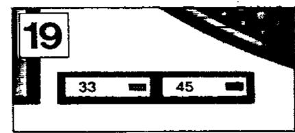
Since the unit has been designed to select 33-1/3 rpm automatically each time you push the power switch to "on", push the 45 rpm speed select button if you play a 45 rpm record (See Fig. 19.)
- Remove the stylus protector, if your cartridge has a detachable one.
- Release the arm clamp
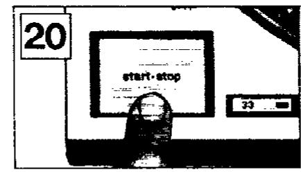
- Push the start-stop button. (See Fig. 20.)
The turntable platter will start to rotate.
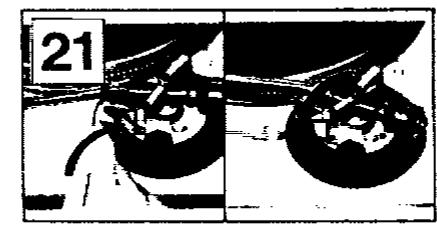
- Set the cueing lever to the up position. (See Fig. 21.)
- Move the tonearm over the desired groove.
- Set the cueing lever to the down position. (See Fig. 21.) The tonearm will descend slowly onto the record and play will begin.
- When play is finished, move the tonearm to the arm rest; secure the tonearm with the arm clamp.
- Push the start-stop button. After the turntable is brought to a stop by means of the electronic brake, turn off the power (mains).
Note:
The electronic brake does not function if the power switch (mains) is turned off before the start-stop button is pushed.
How to suspend play
Set the cueing lever to the "up" position.
The stylus tip of the cartridge will be lifted from the record.
When you play a 45-rpm record with a large center hole
Place the 45-rpm adaptor on the center spindle. Push the 45 speed select button.
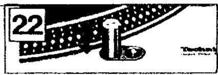
Stylus illuminator (See Fig. 22.)
This unit is provided with a stylus illuminator for illuminating the stylus tip during play.
By pressing the stylus illuminator switch, the stylus illuminator is raised into position for illuminating the stylus tip. When not in use, keep the stylus illuminator lowered through depression.
Note:
The switch must be firmly engaged.
Incomplete depression of the switch will not raise the illuminator even though the lamp is lit.
Adjustments
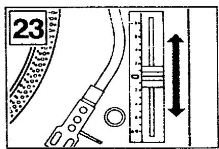
Pitch control (fine adjustment of speed) (See Figs. 23 and 24.)
When the pitch control knob is located at the center of the position after turning on the power, the green LED indicator is lit showing the operating condition for the predetermined speed (either 33-1/3 or 45 rpm). The pitch control is variable in a range of 0 ± 8% .
Figures on the indicator show approximate percentages for variable pitch control.
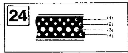
When the strobe dots in 4 stages marked at the peripheral edge of the turntable appear to be stationary, variation of individual pitches is shown. (See Fig. 24.)
When (1) appears stationary, it shows a +6% pitch variation.
When (2) appears stationary, it shows a +3.3% pitch variation.
When (3) appears stationary, it shows normal turntable speed, 3313 or 45 rpm.
When (4) appears stationary, it shows a -3.3% pitch variation.
Note:
The strobe-illumination of this unit employs a strobe-illuminator LED synchronized with the precise quartz frequency.
For fine adjustment of the turntable speed, be sure to effect the adjustment according to the LED illumination.
Also. keep the reset button released.
The LED illumination is not synchronized using fluorescent lamps.
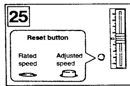
Reset button (See Fig. 25.)

The turntable rotates at the rated speed (33-1/3 or 45 rpm) no matter where the pitch control knob is positioned, and the green LED indicator is illuminated.

The turntable rotates at the speed which has been adjusted by the pitch control knob.
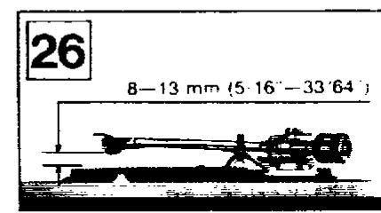
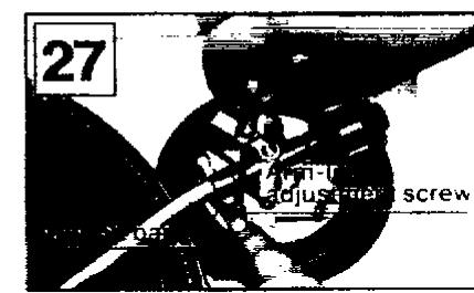
■ Adjustment of arm-lift height
(See Figs. 26 and 27.)
The arm-lift height (distance between the stylus tip and record surface when the cueing lever is raised) has been adjusted at the factory before shipping to approximately 8-13 mm.
If the clearance becomes too narrow or too wide, turn the adjustment screw clockwise or counterclockwise while pushing the arm lift down.
Clockwise rotation
distance between the record and stylus tip is decreased.
Counterclockwise rotation
—distance between the record and stylus tip is increased. Note:
As the adjusting screw has a hexagonal head, be sure to make the adjustment while depressing the arm lift, or the screw will not move freely.
Also be sure that the hexagonal head retracts correctly into the arm lift when the latter is released.
Notes and maintenance
Use utmost care when handling the platter and when placing it on the motor shaft to prevent possible damage to the magnet.
Do not turn "on" the power supply, with the turntable platter detached.
Before detaching or attaching the headshell, be sure to turn the power of the amplifier or receiver off.
Detaching or attaching of the headshell with the volume control turned up may cause damage to the speakers.
When play is finished, be sure to secure the tonearm with the arm clamp.
After play is finished, if the unit is not to be used for some time, care should be taken to secure the tonearm to protect the stylus tip.
For the same reason, the stylus protector should also be attached.
Dust and dirt should be carefully removed from stylus tip or records.
Dust and dirt on the stylus tip or record may not only result in deterioration of tone quality, but also cause undue wear of the record and the stylus tip itself.
Special stylus tip brushes and record cleaners can be purchased in most electronic supply houses.
■ Wipe the headshell terminals from time to time.
Dust and dirt at the headshell terminals may result in increased "HUM" noise or intermittent sound. Use a soft dry cloth to clean the headshell terminals.
■ Wipe the dust cover and turntable base with a soft, dry cloth.
Never use any cleaners containing alcohol, benzine or thinner.
Use of a chemical dust cloth should also be avoided. Be sure that the dust cover is not exposed to insecticide spray.
To remove stubborn finger prints or grease spots, detach the dust cover and disconnect the AC power plug.
Use a soft cloth slightly moistened with a mild soap and water solution.
Do not wipe the dust cover during play, or the tonearm may be attracted toward the dust cover due to the generation of static electricity
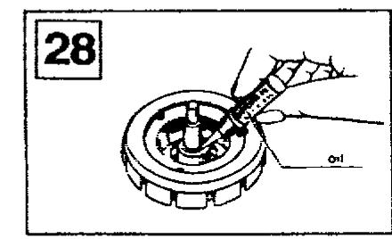
Lubrication (See Fig.28.)
Apply 2 or 3 drops of oil once after every 2000 hours of operation.
The time interval is much longer than that for conventional type motors (200-500 hours).
Please purchase original oil. (Part number is SFWO 010.)
■ Transportation of the unit to distant places for removal and the like.
Pack up the unit in the reverse order to that for unpacking, using the packing materials furnished when the unit was purchased. Should there be no such packing materials, be sure to take the following steps
-
Remove the turntable platter together with the turntable mat, and wrap it up to prevent any damage to them.
-
Return the tonearm to the arm rest, and affix it with tape or the like.
-
Remove the balance weight and the headshell/cartridge from the tonearm and place them in a separate container, and then wrap it up to avoid any damage to it.
-
Wrap up the turntable base with a blanket or soft paper also to prevent any possible damage to it.
Specifications
General
Power supply: 110-120/220-240 V, 50/60 Hz
Power consumption:
Dimensions
W× H× D
Weight:
453× 162× 360mm
12.5 kg
■Turntable section
Type:
Quartz direct drive
Manual turntable
Drive method:
Direct drive
Brushless DC motor
Turntable platter
Aluminum diecast
Diameter 332 mm
Weight 2 kg
Turntable speeds:
33-1/3 r/min and 45 r/min
Starting torque:
1.5 kg·cm
Build-up characteristics: 0.7 s. from standstill to 33-1/3 r/min
Braking system:
Electronic brake
0.01% W.R.M.S
0.025% W.R.M.S (JIS C5521)
± 0.035% peak (IEC 98A Weighted)
This rating refers to turntable assembly alone, excluding effects of record, cartridge or tonarm, but including platter. Measured by obtaining signal from built-in frequency generator of motor assembly.
Rumble:
-56 dB (IEC 98A Unweighted)
-78 dB (IEC 98A Weighted)
■ Tonearm section
Type:
Universal
Effective length:
230mm
Arm height adjustment range:
31.8-37.8 mm
Overhang:
15mm
Effective mass:
12g (without cartridge)
Offset angle:
22irc
Friction:
Less than 7 mg (lateral, vertical)
Tracking error angle:
Within 2irc32' (at the outer groove
of 30 cm :record)
Within 0irc32' (at the inner groove
of 30 cm record)
Stylus pressure
0-2.5g
adjustment range:
Applicable cartridge
weight range:
6-10g
13.5-17.5 g (including headshell)
(with auxiliary
9.5-13g
17-20.5 g (including headshell)
(with shell weight)
3.5-6.5g
11-14 g (including headshell)
Headshell weight:
7.5g
Note:
Specifications are subject to change without notice.
Weight and dimensions are approximate.
Features
Total quartz locked continuous pitch adjustment about ± 8%
Quartz-phase-locked control means almost perfect accuracy of turntable rotation.
But with most quartz turntables, this accurate control circuit must be cut out when the pitch control is employed.
With the SL-1200LTD. however, pitch is variable continuously (analogically) by up to ± 8% under total quartz-locked control. The pitch is controlled with a large sliding lever, located to the right of the turntable platter.
Four lines of platter markings are also provided indicating +6% , +3.3% , 0% (exact rated speed) and -3.3% change from rated speed.
Aluminum diecast cabinet and special heavy rubber base material provide acoustic isolation
The effects of external vibrations are dramatically reduced in the turntable by this new turntable construction.
The turntable base is precision-made aluminum diecast. And the underside of the main base is made of a heavy rubber material which has excellent vibration resistance and absorbing characteristics. The turntable platter is also vibration-damped with specially fabricated rubber matting in the underside along with the thick turntable sheet (rubber mat). Four large-size insulating feet also help to absorb unwanted vibrations.
These features make SL-1200LTD ideal for use with extra-high sound pressure levels.
High torque for fast starts
The integral rotor/platter motor delivers 1.5kgdot cm (1.3 lb·in) starting torque. This high torque gives very quick starts enabling the platter to reach 33-1/3 rpm within 0.7 s. (a quarter of a turn). This is a big advantage in many professional applications where fast cueing is a necessity.
Stylus illuminator for low-light conditions
You'll appreciate the stylus illuminator when you are using the turntable under low-light conditions. The illuminator can be hidden in the turntable base. Should you need it, simply push a button and it will pop up gently and cast a beam of light across the disc in the area traversed by the tonearm. You can then clearly see the spaces between the selections on the record, and cue the arm exactly where you want it. The illuminator can then be pushed back down into the base.
■ High sensitivity, low mass, glimbal suspension tonearm
The highly sensitive tonearm features a genuine gimbal suspension, the rotational center of which is precisely defined at one point. Bearings are finished to a tolerance of ± 0.5 microns. This, and the extra-closeness of pivot center to the bearings, result in the minimal friction of 7mg (0.007 g) for both horizontal and vertical movement. Add to this the low 12-gram effective tonearm mass (including headshell, without cartridge) and you have a tonearm compatible with the wide range of compliances found in today's cartridges. If you choose a popular high compliance MM cartridge, the low range resonance frequency will appear in the correct area to avoid warp frequencies of records, but without entering the low end of the audio spectrum. This tonearm is provided with a computer designed, light-weight, high-rigidity headshell made of single-piece diecast aluminum to resist partial vibration. The universal design allows headshell interchangeability. Contacts are gold-plated.
Helicoid tonearm height adjustment
Arm height is adjustable within a range of 6 mm to accommodate varying cartridge dimensions. Adjustments are done with a precision-made helicoid.
Other fine features
- Quick stops are achieved with a fully electronic braking system.
A strobe illuminator is provided The stroboscope is controlled by the extremely stable quartz oscillator, rather than potentially unstable AC line frequency. - Power on/off control built-in strobe illuminator for ease-of-operation.
- Soft-touch start-stop switch allowing precision control capability without the annoyance of accidental operation.
- Technics integral rotor/platter motor construction with full cycle detection FG.

For longer and safer use of this unit
In order to receive the best service from this unit, and for the safest operation, carefully read the following information.
Power source
It is very dangerous to use this unit at a voltage which is different from the rated voltage.
There is danger of combustion if the unit is connected to a power source which is different from the rated voltage.
Be very careful concerning this point.
Direct current cannot be used.
There are some places, such as ships, where direct current is used as the power source. Before connecting the unit, confirm the power source.
Connection of power cord
Be sure to never touch the power cord with wet hands because there is danger of electric shock. This is true, of course, of all electric equipment.
Do not pull the power cord.
Never pull the power cord to disconnect it. Always pull the plug only.
■ Location of unit
Choose a place which is not in direct sunlight.
Select a place which will assure good ventilation.
Never place heating equipment nearby.
Be sure to keep stoves and other sources of heat away from this unit, because heat radiated by such equipment may cause deformation of plastic parts or damage the cabinet, or, at worst, cause a fire.
Especially for families with children
Take care that no small items, such as metal objects, are put inside this unit.
In addition, children should be especially warned not to put anything into the ventilation holes, such as toys or a screwdriver, because these things may cause an electric shock or result in a malfunction of the unit.
If water spills on the unit.
If water should happen to spill on the unit, from an overturned vase for example, there is danger of fire or electric shock. Disconnect the power plug from the electric outlet immediately and contact the store from which the unit was purchased.
Reconstruction can cause accidents.
Absolutely never try to remodel, reconstruct or repair this unit yourself. Do not attempt to touch any internal parts because to do so may result in an electric shock or other accident.
■ Be sure the power is off.
After you have finished using this unit, check once more to be sure that the power is off. If the unit is left with the power on for a long period of time, it may not only be damaged, thus shortening its useful life, but may also lead to a dangerous accident.
Matsushita Electric Industrial Co., Ltd.
Central P.O. Box 288, Osaka 530-91, Japan
- Technics
- SL-1200LTD
- Operating instructions
- Parts identification
- Assembly and set-up
- Caution for AC mains lead (For United Kingdom)
- CAUTION!
- IMPORTANT
- Before use
- How to replace the fuse
- Caution:
- ■ Checklist of parts
- Installation of turntable platter
- Installation of cartridge (See Fig. 3.)
- (For the unit without Cartridge)
- ■ Adjustment of overhang (See Fig. 5-1.)
- (For the unit with overhang gauge)
- ■ Adjustment of overhang (See Fig. 5-2.)
- (For the unit without overhang gauge)
- Installation of headshell (See Fig. 6.)
- ■ Installation of balance weight (See Fig. 7.)
- Adjustments of horizontal zero (0) balance and stylus pressure
- Note:
- (A)
- (B)
- (C)
- ■ Installation of dust cover (See Fig. 15.)
- Adjustment of anti-skating control
- ■ Adjustment of tonearm height (See Fig. 14.)
- Placement
- Connections
- Connect the output terminals (See Fig. 17.)
- Connect the AC power plug (mains)
- How to operate
- How to suspend play
- When you play a 45-rpm record with a large center hole
- Stylus illuminator (See Fig. 22.)
- Adjustments
- Pitch control (fine adjustment of speed) (See Figs. 23 and 24.)
- Reset button (See Fig. 25.)
- ■ Adjustment of arm-lift height
- Notes and maintenance
- Specifications
- General
- ■Turntable section
- ■ Tonearm section
- Features
- Total quartz locked continuous pitch adjustment about ± 8%
- Aluminum diecast cabinet and special heavy rubber base material provide acoustic isolation
- High torque for fast starts
- Stylus illuminator for low-light conditions
- ■ High sensitivity, low mass, glimbal suspension tonearm
- Helicoid tonearm height adjustment
- Other fine features
- For longer and safer use of this unit
- Power source
- Connection of power cord
- ■ Location of unit
- Never place heating equipment nearby.
- Especially for families with children
- If water spills on the unit.
- Reconstruction can cause accidents.
- ■ Be sure the power is off.
Marque : PANASONIC
Modèle : SL1200LTD
Catégorie : Platine vinyle