XTWALL - Extendeur AV Smart-AVI - Gratis bruksanvisning og manual
Finn enhetens veiledning gratis XTWALL Smart-AVI i PDF-format.

Brukerspørsmål om XTWALL Smart-AVI
0 spørsmål om dette apparatet. Svar på dem du kjenner, eller still ditt eget.
Still et nytt spørsmål om dette apparatet
Last ned instruksjonene for din Extendeur AV i PDF-format gratis! Finn veiledningen din XTWALL - Smart-AVI og ta den elektroniske enheten tilbake i hendene. På denne siden er alle dokumenter som er nødvendige for bruken av enheten din publisert. XTWALL av merket Smart-AVI.
BRUKSANVISNING XTWALL Smart-AVI
Technical Specifications
| XTWALL SPECIFICATIONS | |
| VGA Data | |
| Format RGBHV, RGsB, YUV, Y/C, CVBS | |
| Resolution | Up to 1900 x 1200 VGA, SVGA, XGA, SXGA |
| Connector type HD | 15 socket |
| Audio | |
| Signal Type Sterco | unbalanced |
| Connector 3.5mm | jack socket |
| Power | |
| Requirements 5VDC | @.5A |
| Connector 2.1mm | DC jack (center +ve) |
| Physical | |
| Dimensions 135 x 90 x 23mm (26 with pcgs) | |
| Weight .8 lbs or .36 kg | |
Recieve on DB9 Male

| Pin No. | Name Description |
| 2 RxD | Receive Data on DB9 Male |
| 3 TxD | Transmit Data on DB9 Male |
| 5 SGND Ground | |
Transmit on DB9 Female

| Pin No. | Name Description |
| 2 | TxD Transmit Data on DB9 Female |
| 3 | RxD Recieve Data on DB9 Female |
| 5 | SGND Ground |
© Copyright 2008 Smart-AVI, All Rights Reserved
Notice
The information contained in this document is subject to change without notice. Smart-AVI makes no warranty of any kind with regard to this material, including but not limited to, implied warranties of merchantability and fitness for any particular purpose.
Smart-AVI will not be liable for errors contained herein or for incidental or consequential damages in connection with the furnishing, performance or use of this material.
No part of this document may be photocopied, reproduced or translated into another language with
out prior written consent from Smart-AVI.
For the complete manual, visit www.smartavi.com.
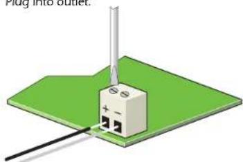
Attaching the Power Supply
- Insert black wire into the positive input (left) and secure.
- Insert white wire into the negative input (right) and secure.
- Plug into outlet.
natural_image
3D diagram of a plug into an outlet with a small component mounted on a green base (no text or symbols)Smart-AM
2840 N. Naomi Ave. Burbank, California 91504 Phone: (818) 565-0011 Facsimile: (818) 565-0020
Smart-AM
SMART AUDIO VIDEO INNOVATION
User Manual
XTWALL
natural_image
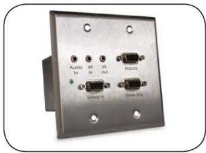
Front panel of a metallic audio device with four connected ports (Audio, WR, ML, Audio Plus) and mounting holes (no visible text or symbols on the device itself)Use a single CAT5 to broadcast high resolution SXGA, Stereo Audio, RS232 and IR up to 1000ft away.
www.smartavi.com
Introduction
The XTWALL allows the extension of a wide range of video and audio formats, RS232, and IR via a sing
Category 5 Unshielded Twisted Pair (UTP) cable.
Features
■ Supports Dual Screens.
■ Uses easy to install, inexpensive CAT-5/5e/6/7/8.
■ Output reaches up to 1,000 feet (300 m).
■ Resolutions up to 1900x1200.
■ 300 MHz Bandwidth.
■ Sends high-resolution UXGA, Stereo Audio and
■ Compatible with Line Level Stereo Audio Signals.
■ High ground loop immunity.
■ Built-in lightning, power surge and transient protection.
■ Designated trimmer in the remote unit to compensate for cable length.
■ Compact Metal Case Enclosure.
■ Supports RS232 and IR
What's in the box?
XTPRO
Please check the contents of the package before beginning installation.
| XTW/ALL Package Content | ||
| Qty | Items | Part No. |
| 1 XT | TWALL Transmitter unit | XTW-TX |
| 1 XT | TWALL Receiver unit | XTW-RX |
| 2 5 | volt dc power supply | PS5D1AW-US |
| 1 | HDD 15 male to male VGA cable (6ft) | CC-VGAMM-06 |
| Optional | ||
| 1 | Audio 3.5 mm stereo mini-plug cable | CC-ADMM06 |
| 1 IR | EYE Receiver | SM-EYE |
| 1 IR | Emitter | SM-LED |
| 1 | Serial m/f DB9 6ft. | CCSERMF06 |
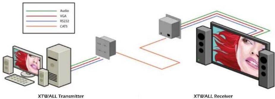
Installation Diagram
flowchart
graph LR
    A["Computer"] -->|Audio| B["XTWALL Transmitter"]
    A -->|VGA| C["XTWALL Receiver"]
    A -->|RS232| C
    A -->|CAT5| C
Connecting The Transmitter
- Connect the output of the computer video card to the video input of the transmitter using the included male to male video cable.
- Connect the output of the computer audio card to the audio input of the transmitter using 3.5mm audio male to male audio cable.
- Connect local monitor to the VGA out of the transmitter.
- Connect external speakers to the transmitter's audio out (Standard 3.5mm stereo miniplug).
- In the back of the unit connect the CAT5 cable that will connect to the receiver (XTW-RX).
\*NOTE: You can not use RS232 and IR at the same time.
Connecting The Receiver
- Connect CAT5 cable (coming from the transmitter) to the back of the receiver.
- Connect 1-2 display monitors to the VGA out connectors on the front of the receiver.
- Connect 1-2 sets of external speakers to the audio output connections on the front of the unit. (Standard 3.5mm stereo Miniplug)
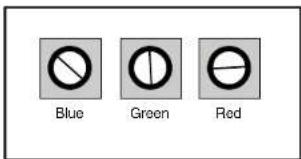
Adjusting and Tuning the Signal
In order to fine tune the signal, adjust the individual dials one at a time starting with GREEN, then BLUE, and lastly RED. As you turn the dials you will notice the colors slightly change as you increase or decrease the strength. All dials should be around the same distance.
Preparing & Connecting System CAT5 Cable
Following is the wiring standard for terminating CAT 5 cable using RJ-45 connector:
Pair 1 Pins 1 & 2
Pair 2 Pins 3 & 6
Pair 3 Pins 4 & 5
Pair 4 Pins 7 & 8
Connectors: RJ-45
Capacitance: 14 pf/ft (46.2 pf/m)
Conductor Gauge: 24 AWG
Impedance: 100 +/- 15 ohms
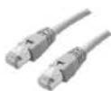
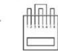
RJ-45