
PHR 630 - Luidspreker PEAVEY - Gratis gebruiksaanwijzing en handleiding
Vind de handleiding van het apparaat gratis PHR 630 PEAVEY in PDF-formaat.


| Type product | Plafondluidspreker (inbouw) |
| Merk | Peavey |
| Model | PHR 630 |
| Frequentiebereik | 90 Hz - 20 kHz (+/- 4 dB) |
| Vermogen (Thru Mode) | 50 W |
| Gevoeligheid | 89 dB SPL (1 m, 1 W) |
| Transformator aftakkingen | 30 W, 15 W, 7,5 W, 3,75 W, 1,9 W (70 V) / 100 V |
| Impedantie (Thru Mode) | 8 ohm (nominaal) |
| Componenten | 6,5" woofer (PP-conus, rubberen omranding) en 3/4" soft dome tweeter |
| Crossover frequentie | 4 kHz |
| Crossover hellingen | 12 dB/oct (tweeter), 6 dB/oct (woofer) |
| Buitenafmetingen (doorsnede x diepte) | 25,9 cm x 21,8 cm |
| Uitsnijddiameter | 19,8 cm |
| Gewicht | 3,4 kg |
| Behuizing | Hoogslagvast polystyreen met stalen achterkast |
| Rooster | Geperforeerd metaal met binnenvoering |
| Aansluiting | 4-polige schroefconnector |
| Montage | Plafondinbouw met klemarmen |
| Secundaire ondersteuning | Seismisch bevestigingspunt voor veiligheidskabel |
| Veiligheid | Schroeven niet te vast aandraaien |
Veelgestelde vragen - PHR 630 PEAVEY
Gebruikersvragen over PHR 630 PEAVEY
0 vraag over dit apparaat. Beantwoord die u kent of stel uw eigen vraag.
Stel een nieuwe vraag over dit apparaat
Download de handleiding voor uw Luidspreker in PDF-formaat gratis! Vind uw handleiding PHR 630 - PEAVEY en neem uw elektronisch apparaat weer in handen. Op deze pagina staan alle documenten die nodig zijn voor het gebruik van uw apparaat. PHR 630 van het merk PEAVEY.
GEBRUIKSAANWIJZING PHR 630 PEAVEY
Frame Construction Ceiling Installation
1
Take the cutout template from the packaging box and punch out along the larger perforated circle. Place the cutout template against the bottom of the ceiling and trace the inside of it. Carefully cut out the ceiling material along the circle.

2
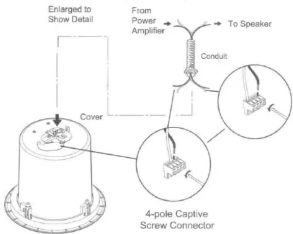
Remove the top cover to access the speaker connector. Attack the speaker wires to the 4-pole captive screw connector. Insert the 4-pole captive screw plug into the connector on back of the speaker. Install the conduit and secure the connections.
3
Replace the top cover and tighten the screws. Insert the speaker through the bottom of the hole in the ceiling.

flowchart
graph TD
    A["Power Amplifier"] --> B["Speaker 1"]
    A --> C["Speaker 2"]
    A --> D["Speaker 3"]
    B --> E["Loop R N N Loop T/R/U"]
    C --> F["Loop R N N Loop"]
    D --> G["Loop R N N Loop"]
    H["To Speakers"] --> I["+"]
    style A fill:#f9f,stroke:#333
    style B fill:#ccf,stroke:#333
    style C fill:#ccf,stroke:#333
    style D fill:#ccf,stroke:#333
Parallel Hookup Wiring Diagram
4
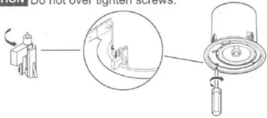
Loosen the four screws on the front baffle(counter clockwise) 1/2 turn. Then tighten the screws (clockwise) until the dog legs clamp the speaker to the ceiling.
CAUTION
Do not over tighten screws.
5
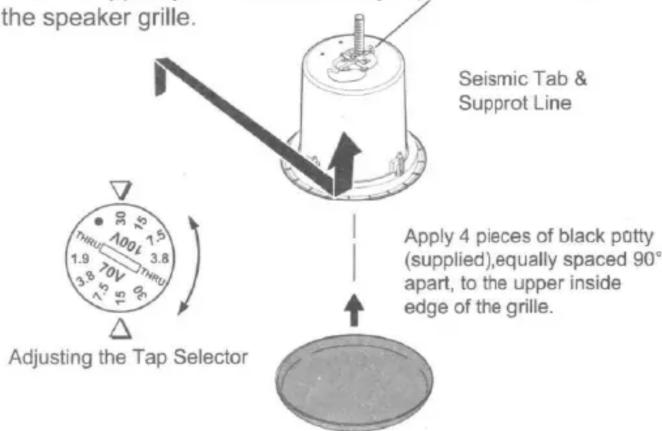
Connect a secondary support line from the seismic tab to a secure support point. Set the rotary tap selector and install the speaker grille.
Peavey 6.5" Metal Can Ceiling Speaker Specifications
Acoustic & Electrical
Frequency Response 90 Hz - 20 kHz, +/- 4 dB
Power handling...... Thru Mode - 50W
Nominal sensitivity.... 89 dB SPL, 1m, 1W
(8 ohms nominal in Thru Mode)
Transformer taps 30W, 15W, 7.5W, 3.75W, 1.9W, (70V)
100V capable
Component 6.5" woofer with 1" VC, PP cone and rubber
surround 3/4" soft dome tweeter
Crossover Frequency.... 4 kHz
Crossover Slopes.... 12 dB/oct. for tweeter, 6 dB/oct. for woofer
Outside Dimensions.... 10.2" X 8.6" (Outer Diameter X Depth)
Cutout diameter....7.8"
Weight 7.6 lbs
General
Enclosure: High impact polystyrene with removable locking installation arms, backcan of formed steel
Conduit capable clamp for wiring, wiring chamber with screw lock.
Perforated metal grille with inner fabric liner for 'blackout'
C-shaped backing plate support included
NOTE: All nominal level are at ±10%.
NOTE: Specifications are subject to change without notice.
68-1065-01 Rev. B
06 09

Merk : PEAVEY
Model : PHR 630
Categorie : Luidspreker